CN202931783U - Potato combined harvester - Google Patents
Potato combined harvester Download PDFInfo
- Publication number
- CN202931783U CN202931783U CN 201220636621 CN201220636621U CN202931783U CN 202931783 U CN202931783 U CN 202931783U CN 201220636621 CN201220636621 CN 201220636621 CN 201220636621 U CN201220636621 U CN 201220636621U CN 202931783 U CN202931783 U CN 202931783U
- Authority
- CN
- China
- Prior art keywords
- chain
- potato
- afer bay
- frame
- fixedly installed
- Prior art date
- Legal status (The legal status is an assumption and is not a legal conclusion. Google has not performed a legal analysis and makes no representation as to the accuracy of the status listed.)
- Expired - Fee Related
Links
Images


Abstract
The utility model discloses a potato combined harvester. The harvester comprises a hitch frame, a front machine frame, a rear machine frame, a reel, a hay knife, a ridging shovel, a conveying chain, a star wheel roller, a lifting chain, an output chain, a land wheel and a transmission device. A lifting adjusting oil cylinder is arranged between the front machine frame and the rear machine frame so that the soil inserting angle and depth of the ridging shovel can be adjusted according to the planting depth of potatoes and loss of the potatoes and harvest leakage are avoided. Match between the conveying chain and the star wheel roller are reasonable, a vibrating roller is additionally arranged, an impurity removing fan is arranged on the conveying chain and an impurity removing manual operation platform is arranged so that the potatoes harvested are clean and quality standard of the potatoes is further improved. The potatoes harvested can be transported directly after being entrucked so that a large amount of labor force and working time are saved and operation is simple and convenient.
Description
Technical field
The utility model relates to a kind of agricultural machinery technological field, is specifically related to a kind of potato combine.
Background technology
great development along with the potato deep process technology, the economic benefit of the increasing and potato of potato product is day by day remarkable, the enthusiasm of peasant planting potato is also more surging, but the plantation of potato and results are the operations that labour intensity is larger, in recent years in order to have alleviated peasant's labour intensity, the field is studied and produced and be applied to potato setter and reaping machine in succession, for the peasant has alleviated labour intensity, many labours have been saved, but also there are some unsatisfactory places in the harvest machinery of using at present, as unclean in receiving, earth is removed unclean, potato is easily damaged and also need people's fixture vehicle etc., still need further to improve.
Summary of the invention
The purpose of this utility model is to provide a kind of potato combine, and this machine net harvesting rate is high, does not damage potato, is not with earth, directly entrucks and carries away.
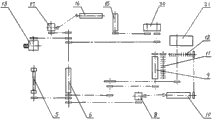
for achieving the above object, the utility model potato combine comprises: hitch frame, forebay, afer bay, straw shift wheel, hay knife, the making ridge shovel, carrier chain, the star-wheel roller, elevating chain, discharging chain, land wheel and transmission device, hitch frame is hinged on frame, forebay and afer bay are hinged, and the lift adjustment oil cylinder is set, straw shift wheel and hay knife support through bearing block respectively and are fixedly installed on forebay, profiling frame and afer bay are hinged, the making ridge shovel is through spade and profiling frame Joint, support through bearing block successively on the frame of making ridge shovel rear end the first carrier chain is set, the second carrier chain, the first star-wheel roller supports through bearing block and is fixedly installed on the second carrier chain rear end, the 3rd carrier chain one side is connected mutually with the first star-wheel roller, the rear end is connected mutually with the second star-wheel roller, elevating chain one side is connected mutually with the second star-wheel roller, the upper end is connected mutually with discharging chain, land wheel is below bearing block is supported and fixed on afer bay, transmission device is fixedly installed on respectively on forebay and afer bay.
Below described the first carrier chain, vibrating roller is set.
Be fixedly installed connecting plate between described profiling frame and forebay, and the adjustment bolt is set between afer bay.
Above described the 3rd carrier chain, the impurity elimination blower fan is set.
Described discharging chain comprises that bent plate chain and inverted T-shaped dial the potato plate, and described inverted T-shaped is dialled the potato plate and is spirally connected and is fixed on the bent plate chain.
Described discharging chain is supported by runner, and described runner supports to be spirally connected through bearing block and is arranged on hoisting frame.
Bottom and the afer bay of described hoisting frame are hinged, and are fixedly installed lift cylinder between upper end and afer bay.
Be fixedly installed artificial removal of impurities operating desk on the afer bay in the described elevating chain outside.
Described transmission device comprises the first reduction box, the second reduction box, the 3rd reduction box, drive sprocket and driving chain.
The utility model is owing to being provided with the lift adjustment oil cylinder between mmi machine frame and afer bay, can adjust making ridge shovel angle of penetration and the degree of depth according to the potato planting degree of depth, guarantee not lose fruit, do not leak receipts, coordinate rationally between carrier chain with between the star-wheel roller, vibrating roller is set in addition, be provided with the impurity elimination blower fan on carrier chain, and removal of impurities manual operation platform, make the potato fruit of results cleaner, further improved the potato quality standard, the utility model is is directly entrucked and carried away the potato of results, saved a large amount of labours and man-hour, simple, convenient.
Below in conjunction with accompanying drawing, the utility model is described in further detail.
Description of drawings
Fig. 1 is the utility model front view schematic diagram.
Fig. 2 is the vertical view schematic diagram of Fig. 1.
Fig. 3 is that schematic diagram is looked on Fig. 1 left side.
Fig. 4 is that the A-A of Fig. 1 is to schematic diagram.
Fig. 5 is that the B of Fig. 2 is to schematic diagram.
Fig. 6 is carrier chain schematic diagram in Fig. 4.
Fig. 7 is the vertical view schematic diagram of Fig. 6.
Fig. 8 is the utility model transmission device transmission schematic diagram.
Embodiment
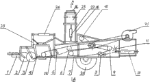
as shown in the figure, the utility model potato combine comprises: hitch frame 1, forebay 25, afer bay 7, straw shift wheel 2, hay knife 3, making ridge shovel 4, carrier chain, the star-wheel roller, elevating chain 15, discharging chain, land wheel 20 and transmission device, hitch frame is hinged on afer bay, forebay and afer bay are hinged, and lift adjustment oil cylinder 24 is set, straw shift wheel and hay knife support through bearing block respectively and are fixedly installed on forebay, profiling frame 19 is hinged with afer bay, the making ridge shovel is through spade and profiling frame Joint, support through bearing block successively on the frame of making ridge shovel rear end the first carrier chain 6 is set, the second carrier chain 9, the first star-wheel roller 11 supports through bearing block and is fixedly installed on the second carrier chain rear end, the 3rd carrier chain 10 1 sides are connected mutually with the first star-wheel roller 11, the rear end is connected mutually with the second star-wheel roller 12, elevating chain 15 1 sides are connected mutually with the second star-wheel roller 12, the upper end is connected mutually with discharging chain 23, land wheel 20 is below bearing block is supported and fixed on afer bay, transmission device is fixedly installed on respectively on forebay and afer bay.
Below described the first carrier chain 6, vibrating roller 5 is set.
25 of described profiling frame 19 and forebaies are fixedly installed connecting plate, and 7 of afer bays arrange the adjustment bolt.
Above described the 3rd carrier chain 10, impurity elimination blower fan 21 is set.
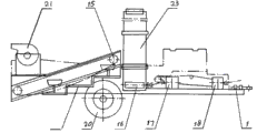
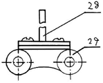
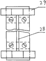
Described discharging chain 23 comprises that bent plate chain 29 and inverted T-shaped dial potato plate 28, and described inverted T-shaped is dialled the potato plate and is spirally connected and is fixed on the bent plate chain.
Described discharging chain 23 is supported by runner 16, and described runner supports to be spirally connected through bearing block and is arranged on hoisting frame 14.
The bottom of described hoisting frame 14 and afer bay 7 are hinged, and are fixedly installed lift cylinder 22 between upper end and afer bay.
Be fixedly installed artificial removal of impurities operating desk 13 on the afer bay in the described elevating chain outside.
Described transmission device comprises the first reduction box 18, the second reduction box 17, the three reduction box 8, drive sprocket and driving chains.
During farm work, tractor-drawn the utility model is gathered in the crops potato, the making ridge shovel is adjusted angle and the depth, cutting grass knife excision weeds, the making ridge shovel is sent the potato and the seedling soil that trip out into the first carrier chain, vibrate hack and filter through the vibration rod, when arriving the 3rd carrier chain, the impurity elimination blower fan is removed seedling soil foreign material, and through the star-wheel roller, potato is transported to elevating chain, people in the elevator process on the removal of impurities workbench can also disease is bad potato and assorted soil remove, discharging chain rises and aims at transport vehicle through lift cylinder, and the potato after results is is directly entrucked and carried away.
During the utility model operation, tractor dynamic power is passed to the first reduction box 18, drive the second reduction box and drive transfer chain and elevating chain work through sprocket wheel, the first reduction box is simultaneously through chain gear transmission straw shift wheel the first carrier chain, the second carrier chain and the first star-wheel roller, and transmission the 3rd reduction box passes through universal coupling, transmission the 3rd carrier chain 10, the second gearbox is by universal coupling transmission discharging chain, the first carrier chain transmission axle head arranges altogether three sprocket wheels and drives respectively the second carrier chain 9, the three reduction boxes 8 and straw shift wheel 2.
Claims (9)
1. potato combine, this reaping machine comprises: hitch frame (1), forebay (25), afer bay (27), straw shift wheel (2), hay knife (3), making ridge shovel (4), carrier chain, the star-wheel roller, elevating chain (15), discharging chain, land wheel (20) and transmission device, it is characterized in that: described hitch frame is hinged on frame, forebay and afer bay are hinged, and lift adjustment oil cylinder (24) is set, straw shift wheel and hay knife support through bearing block respectively and are fixedly installed on forebay, profiling frame (19) is hinged with afer bay, the making ridge shovel is through spade and profiling frame Joint, support through bearing block successively on the frame of making ridge shovel rear end the first carrier chain (6) is set, the second carrier chain (9), the first star-wheel roller (11) supports through bearing block and is fixedly installed on the second carrier chain rear end, the 3rd carrier chain (10) one sides are connected mutually with the first star-wheel roller (11), the rear end is connected mutually with the second star-wheel roller (12), elevating chain (15) one sides are connected mutually with the second star-wheel roller (12), the upper end is connected mutually with discharging chain (23), land wheel (20) is below bearing block is supported and fixed on afer bay, transmission device is fixedly installed on respectively on forebay and afer bay.
2. potato combine according to claim 1, is characterized in that: vibrating roller (5) is set below described the first carrier chain (6).
3. potato combine according to claim 1, is characterized in that: be fixedly installed connecting plate between described profiling frame (19) and forebay (25), and between afer bay (7), the adjustment bolt be set.
4. potato combine according to claim 1, is characterized in that: impurity elimination blower fan (21) is set above described the 3rd carrier chain (10).
5. potato combine according to claim 1 is characterized in that: described discharging chain (23) comprises that bent plate chain (29) and inverted T-shaped dial potato plate (28), and described inverted T-shaped is dialled the potato plate and is spirally connected and is fixed on the bent plate chain.
6. potato combine according to claim 1 is characterized in that: described discharging chain (23) is supported by runner (16), and described runner supports to be spirally connected through bearing block and is arranged on hoisting frame (14).
7. potato combine according to claim 6, it is characterized in that: bottom and the afer bay of described hoisting frame are hinged, and are fixedly installed lift cylinder (22) between upper end and afer bay.
8. potato combine according to claim 1, is characterized in that: be fixedly installed artificial removal of impurities operating desk (13) on the afer bay (7) outside described elevating chain (15).
9. potato combine according to claim 1, it is characterized in that: described transmission device comprises the first reduction box (18), the second reduction box (17), the 3rd reduction box (8), drive sprocket and driving chain.
Priority Applications (1)
| Application Number | Priority Date | Filing Date | Title |
|---|---|---|---|
| CN 201220636621 CN202931783U (en) | 2012-11-28 | 2012-11-28 | Potato combined harvester |
Applications Claiming Priority (1)
| Application Number | Priority Date | Filing Date | Title |
|---|---|---|---|
| CN 201220636621 CN202931783U (en) | 2012-11-28 | 2012-11-28 | Potato combined harvester |
Publications (1)
| Publication Number | Publication Date |
|---|---|
| CN202931783U true CN202931783U (en) | 2013-05-15 |
Family
ID=48316059
Family Applications (1)
| Application Number | Title | Priority Date | Filing Date |
|---|---|---|---|
| CN 201220636621 Expired - Fee Related CN202931783U (en) | 2012-11-28 | 2012-11-28 | Potato combined harvester |
Country Status (1)
| Country | Link |
|---|---|
| CN (1) | CN202931783U (en) |
Cited By (2)
| Publication number | Priority date | Publication date | Assignee | Title |
|---|---|---|---|---|
| CN103947366A (en) * | 2014-05-14 | 2014-07-30 | 山东理工大学 | American ginseng seedling cutting harvester |
| CN104904435A (en) * | 2014-03-10 | 2015-09-16 | 托克托县宏昌机械制造有限公司 | Potato sundry removing machine |
-
2012
- 2012-11-28 CN CN 201220636621 patent/CN202931783U/en not_active Expired - Fee Related
Cited By (3)
| Publication number | Priority date | Publication date | Assignee | Title |
|---|---|---|---|---|
| CN104904435A (en) * | 2014-03-10 | 2015-09-16 | 托克托县宏昌机械制造有限公司 | Potato sundry removing machine |
| CN103947366A (en) * | 2014-05-14 | 2014-07-30 | 山东理工大学 | American ginseng seedling cutting harvester |
| CN103947366B (en) * | 2014-05-14 | 2015-11-04 | 山东理工大学 | Seedling reaping machine cut by a kind of American Ginseng |
Similar Documents
| Publication | Publication Date | Title |
|---|---|---|
| CN202222146U (en) | Potato harvester | |
| CN102783302B (en) | Self walking type garlic combine harvester | |
| CN202818956U (en) | Potato combine harvester | |
| KR20160014950A (en) | Tractor trailed type welsh onion harvester | |
| CN204180488U (en) | Underground corps is sowed, apply fertilizer, spray insecticide, results power drive car | |
| CN201230470Y (en) | Peanut indirect harvester | |
| CN202697236U (en) | Self-propelled garlic combine harvester | |
| CN204907139U (en) | Small -size self -propelled garlic combine harvester | |
| CN202524757U (en) | Potato combine harvester | |
| CN207505425U (en) | Potato combine | |
| KR101330093B1 (en) | Spinach harvester | |
| CN202931783U (en) | Potato combined harvester | |
| CN204305647U (en) | A kind of potato collecting machine | |
| CN103004360B (en) | Stubble removing and remained film recovering machine | |
| CN204180536U (en) | The hydraulic pressure power-driven system of preposition driving harvester for peanut | |
| CN208317408U (en) | A kind of full-automatic garlic combined harvester | |
| CN104303712B (en) | A kind of potato collecting machine | |
| CN204180528U (en) | Garlic, potato harvesting apparatus | |
| CN202931785U (en) | Potato harvester | |
| CN203788746U (en) | Peanut picker | |
| CN202918693U (en) | Potato combine | |
| CN204180534U (en) | Preposition driving harvester for peanut | |
| CN2556905Y (en) | Harvester for tube crop | |
| CN211960096U (en) | Novel self-propelled garlic combine's of track conveying structure | |
| CN102792824A (en) | Multifunctional peanut and maize harvester |
Legal Events
| Date | Code | Title | Description |
|---|---|---|---|
| C14 | Grant of patent or utility model | ||
| GR01 | Patent grant | ||
| CF01 | Termination of patent right due to non-payment of annual fee |
Granted publication date: 20130515 Termination date: 20201128 |
|
| CF01 | Termination of patent right due to non-payment of annual fee |