Disclosure of Invention
The invention aims to provide an automatic cleaning system for a pipe sheet die, which solves a series of problems of high labor intensity, high cost, partial damage to the die, air pollution, influence on the body health of workers and the like in the conventional manual cleaning mode.
In order to achieve the above purpose, the invention provides the following technical scheme:
the utility model provides an automatic cleaning system of section of jurisdiction mould, the automatic cleaning system of section of jurisdiction mould includes:
the truss mechanism comprises a truss main body and vertical telescopic columns arranged on the truss main body, and the vertical telescopic columns can move transversely, longitudinally and vertically along the truss main body respectively;
the cleaning device comprises a mounting assembly, a disc brush assembly and a rolling brush assembly, the mounting assembly is connected with the bottom end of the vertical telescopic column, and the disc brush assembly and the rolling brush assembly are mounted on the mounting assembly and used for cleaning attachments on the surface of the segment mold;
and the control system is in communication connection with the truss mechanism and the cleaning device and is used for controlling the cleaning device to move so as to automatically clean attachments on the surface of the segment mold.
Optionally, the installation assembly comprises a truss connecting piece, a connecting frame and an installation main board which are connected, the truss connecting piece is connected with the bottom end of the vertical telescopic column, and the disc brush assembly and the rolling brush assembly are installed on the installation main board.
Optionally, the dish brush subassembly includes dish brush, dish brush motor mount pad, dish brush bearing, dish brush shaft coupling and dish brush extension shaft, dish brush motor mount pad is installed on the installation mainboard, the dish brush motor is installed on the dish brush motor mount pad, and with control system communication is connected, dish brush coupling joint in dish brush motor mount pad dorsad one side of dish brush motor, and with dish brush motor transmission is connected, the dish brush bearing sets up dish brush shaft coupling with between the dish brush motor mount pad, the one end of dish brush extension shaft connect in the dish brush shaft coupling, the other end of dish brush extension shaft connect in the dish brush.
Optionally, the number of the disc brush assemblies is two, and the two disc brush assemblies are installed on the installation main board in parallel.
Optionally, the round brush subassembly includes round brush motor, round brush motor mount pad, round brush shaft coupling, round brush bearing and round brush, the round brush motor is installed on the round brush motor mount pad, and with control system communication is connected, round brush motor mount pad swing joint in on the installation mainboard, the round brush shaft coupling connect in the round brush motor mount pad dorsad one side of round brush motor to be connected with the transmission of round brush motor, the round brush bearing sets up between round brush shaft coupling and the round brush dish brush motor mount pad, the round brush connect in the round brush shaft coupling.
Optionally, the sweeping device further comprises a rolling brush displacement sliding plate, a displacement sliding plate pushing electric cylinder and a rolling brush inclination pushing electric cylinder, and the displacement sliding plate pushing electric cylinder and the rolling brush inclination pushing electric cylinder are both in communication connection with the control system;
the rolling brush displacement sliding plate is movably mounted on the mounting main plate, a central shaft lug seat, a first electric cylinder lug seat and a second electric cylinder lug seat are arranged on the rolling brush displacement sliding plate, a rotating central shaft is arranged on the rolling brush motor mounting seat and connected to the central shaft lug seat, the displacement sliding plate pushes an electric cylinder to be mounted on the mounting main plate, the movable end of the displacement sliding plate pushing the electric cylinder is connected to the first electric cylinder lug seat, and the displacement sliding plate pushes the electric cylinder to move in a telescopic mode so as to drive the rolling brush displacement sliding plate to move relative to the mounting main plate;
the stiff end that round brush slope promoted electric jar connect in second electric jar ear seat, the round brush slope promotes the expansion end of electric jar through electric jar pivot connect in round brush motor mount pad, round brush slope promotes electric jar concertina movement and can drive the round brush subassembly slope.
Optionally, the cleaning device further comprises a node rotating assembly, the node rotating assembly comprises a first worm gear reducer, a first worm rotating motor, a second worm gear reducer and a second worm rotating motor, a housing of the first worm gear reducer is mounted on the connecting frame, a housing of the first worm rotating motor is connected with a housing of the first worm gear reducer, an output shaft of the first worm rotating motor is connected with a worm of the first worm gear reducer, a housing of the second worm gear reducer is mounted on the mounting main plate, a worm wheel of the second worm gear reducer is connected with a worm wheel of the first worm gear reducer through a connecting piece, a housing of the second worm rotating motor is connected with a housing of the second worm gear reducer, and an output shaft of the second worm rotating motor is connected with a worm of the second worm gear reducer;
the first worm rotating motor and the second worm rotating motor are in communication connection with the control system;
the first worm rotates the motor and rotates and can drive installation mainboard slope, the second worm rotates the motor and rotates and can drive the installation mainboard is rotatory.
Optionally, the automatic duct piece mold cleaning system further comprises a dust removal system for collecting dust generated by the cleaning device during operation.
Optionally, dust pelletizing system includes draught fan, hard induced duct, soft induced duct, rose box and suction hood, the draught fan with the rose box is all installed truss mechanism is last, the draught fan with the control system communication is connected, be provided with the filter screen in the rose box, the bottom of rose box is provided with the dust hopper for collect by the dust that the filter screen blockked, the suction hood is installed cleaning device is last, the import of rose box is passed through soft induced duct with dust absorption mouth on the suction hood is connected, the export of rose box is passed through hard induced duct with the air intake connection of draught fan, the draught fan is provided with the air outlet for discharge the air after filtering.
Optionally, the dust removal system further comprises a dust remover pulse generator, the dust remover pulse generator is mounted on the truss mechanism, and the dust remover pulse generator is communicated with the filter box and is in communication connection with the control system.
Has the advantages that:
the automatic cleaning system for the duct piece mold comprises a truss mechanism, a cleaning device and a control system, wherein the truss mechanism comprises a truss main body and vertical telescopic columns arranged on the truss main body, and the vertical telescopic columns can respectively move along the transverse direction, the longitudinal direction and the vertical direction of the truss main body; the cleaning device comprises a mounting assembly, a disc brush assembly and a rolling brush assembly, the mounting assembly is connected with the bottom end of the vertical telescopic column, and the disc brush assembly and the rolling brush assembly are both mounted on the mounting assembly and used for cleaning attachments on the surface of the duct piece mold; the control system is in communication connection with the truss mechanism and the cleaning device and is used for controlling the cleaning device to move so as to automatically clean attachments on the surface of the segment mold. The automatic cleaning system for the duct piece mold is suitable for molds of different types, can be installed on a duct piece production line for use, achieves full-automatic continuous cleaning, has clean and comprehensive surface of the cleaned duct piece mold, is high in cleaning speed, can greatly reduce the labor intensity of workers, saves the labor cost, reduces the production cost of concrete prefabricated parts, and does not have a series of problems of partial damage to the mold, air pollution, influence on the health of the workers and the like. Meanwhile, the quality problems of product surface damage and the like caused by incomplete cleaning after the concrete prefabricated part is demoulded can be effectively reduced, the repairing amount is reduced, and the surface smoothness is improved.
Detailed Description
The technical solutions in the embodiments of the present invention will be described clearly and completely below, and it is obvious that the described embodiments are only a part of the embodiments of the present invention, and not all embodiments. All other embodiments, which can be derived from the embodiments of the present invention by a person skilled in the art, are within the scope of the present invention.
The present invention will be described in detail with reference to examples. It should be noted that the embodiments and features of the embodiments of the present invention may be combined with each other without conflict.
The automatic cleaning system for the duct piece mold is suitable for molds of different types, can be installed on a duct piece production line to be used, achieves full-automatic continuous cleaning, can greatly reduce the labor intensity of workers and save the labor cost, thereby reducing the production cost of a concrete prefabricated part, and avoiding a series of problems of partial damage to the mold, air pollution, influence on the health of the workers and the like. Meanwhile, the quality problems of product surface damage and the like caused by incomplete cleaning after the concrete prefabricated part is demoulded can be effectively reduced, the repairing amount is reduced, and the surface smoothness is improved.
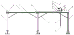
As shown in fig. 1 to 7, the automatic duct piece mold cleaning system of the present invention includes a truss mechanism, a cleaning device, and a control system, wherein the truss mechanism includes a truss main body and a vertical telescopic column 10 disposed on the truss main body, and the vertical telescopic column 10 can move along the truss main body in the horizontal direction, the longitudinal direction, and the vertical direction, respectively.
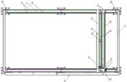
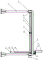
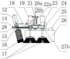
Specifically, as shown in fig. 1 to 3, the truss main body is a rectangular frame structure composed of support legs 1, main beams 2 and end beams 4, six support legs 1, two main beams 2 parallel to each other and two end beams 4 parallel to each other are specifically provided, and the upper ends of the support legs and the main beams 2 are fixed by using inclined supports 5 to enhance the overall firmness of the truss main body. The main beam 2 is provided with the cross beam 3, the vertical telescopic column 10 is installed on the cross beam 3, the main beam 2 is provided with a longitudinal walking motor installation seat 44, the longitudinal walking motor 9 is arranged on the main beam 2, the main beam 2 is further provided with a displacement slide rail 41 and a displacement walking rack 43 which are matched with each other, the displacement walking rack 43 is connected with the cross beam 3, an output shaft of the longitudinal walking motor 9 is in transmission connection with a longitudinal synchronous walking transmission shaft 42, the longitudinal synchronous walking transmission shaft 42 is in transmission connection with the displacement walking rack 43, and the longitudinal walking motor 9 can drive the displacement walking rack 43 to longitudinally move along the displacement slide rail 41 through the longitudinal synchronous walking transmission shaft 42, so that the cross beam 3 and the vertical telescopic column 10 are driven to longitudinally move together.
Be provided with horizontal walking motor 7 on the crossbeam 3, matched with displacement slide rail 41 and displacement walking rack 43, displacement walking rack 43 is connected with vertical flexible post 10, the output shaft transmission of horizontal walking motor 7 is connected with horizontal synchronous walking transmission shaft, horizontal synchronous walking transmission shaft is connected with displacement walking rack 43 transmission, so setting, horizontal walking motor 7 can drive displacement walking rack 43 through horizontal synchronous walking transmission shaft and carry out lateral shifting along displacement slide rail 41, and then drive crossbeam 3 and vertical flexible post 10 lateral shifting together.
Be provided with vertical walking motor 8 on vertical flexible post 10, matched with displacement slide rail 41 and displacement walking rack 43, displacement walking rack 43 is connected with vertical flexible post 10, vertical walking motor 8's output shaft transmission is connected with vertical synchronous walking transmission shaft, vertical synchronous walking transmission shaft is connected with displacement walking rack 43 transmission, so setting, vertical walking motor 8 can drive displacement walking rack 43 through vertical synchronous walking transmission shaft and carry out lateral shifting along displacement slide rail 41, and then drive vertical flexible post 10 vertical removal together.
Further, limiting buffers 40 are arranged at two ends of the main beam 2 and two ends of the cross beam 3, so that the vertical telescopic column 10 can be limited in longitudinal and transverse movement.
The cleaning device comprises a mounting assembly, a disc brush assembly and a rolling brush assembly, the mounting assembly is connected with the bottom end of the vertical telescopic column 10, and the disc brush assembly and the rolling brush assembly are both mounted on the mounting assembly and used for cleaning attachments on the surface of the segment mold.
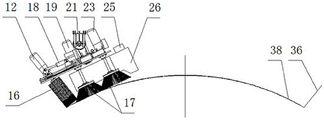
Specifically, the connection mode of installation component and vertical flexible post 10 can be selected for dismantling the connection, for example screw connection, buckle connection or other reasonable connection modes, and dish brush subassembly and round brush subassembly are installed back on the installation component, can follow installation component and vertical flexible post 10 and carry out horizontal, vertical and vertical removal together, and then are used for cleaning the attachment on section of jurisdiction mould surface, and wherein, dish brush subassembly is arranged in cleaning the attachment on die block 38 surface in the section of jurisdiction mould, and the round brush subassembly is arranged in cleaning the attachment on side form 37, end mould 36 surface in the section of jurisdiction mould.
The control system is in communication connection with the truss mechanism and the cleaning device and is used for controlling the cleaning device to move so as to automatically clean attachments on the surface of the segment mold.
Specifically, control system and truss mechanism in vertically walk motor 9, transversely walk motor 7 and vertical walking motor 8 communication connection, control system specifically is electric automation control, during specific setting, all be provided with electric circuit on truss mechanism's girder 2, crossbeam 3 and the vertical flexible post 10 and hold in the palm chain 6 to realize control system and vertically walk motor 9, transversely walk motor 7 and vertical walking motor 8's communication connection, so setting can realize above-mentioned removal process through control system. Simultaneously, control system still with cleaning device in dish brush subassembly and the round brush subassembly communication be connected, can be so that install the cleaning device in vertical flexible post 10 bottom according to the orbit of prediction, with certain velocity of motion, certain brush head rotational speed, apply in waiting to clean certain pressure in section of jurisdiction mould surface, realize the effect of accurate cleaning.
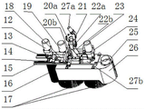
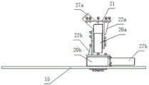
As shown in fig. 4 and 5, in the embodiment of the present invention, the mounting assembly includes a truss connecting member 21, a connecting frame 22a and a mounting main board 15 which are connected, the truss connecting member 21 is connected to the bottom end of the vertical telescopic column 10, and the disc brush assembly and the rolling brush assembly are both mounted on the mounting main board 15.
Specifically, the truss connecting piece 21 is a connecting flange, the bottom end of the vertical telescopic column 10 is provided with an assembling flange 11, and the connecting flange and the assembling flange 11 are fixedly connected through screws, so that the fixed connection between the truss connecting piece 21 and the vertical telescopic column 10 can be realized. The installation mainboard 15 is provided with dish brush installation position and round brush installation position, and during the assembly, dish brush subassembly and round brush subassembly are installed respectively on dish brush installation position and round brush installation position, and its mounting means can select for joint fixation, fix with screw or other reasonable mounting means.
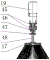
As shown in fig. 4, 5, 8 and 9, in an embodiment of the present invention, the disc brush assembly includes a disc brush 17, a disc brush motor mounting seat 45, a disc brush bearing 46, a disc brush coupler 47 and a disc brush extension shaft 48, the disc brush motor mounting seat 45 is mounted on the mounting main board 15, the disc brush motor is mounted on the disc brush motor mounting seat 45 and is in communication connection with the control system, the disc brush coupler 47 is connected to a side of the disc brush motor mounting seat 45 facing away from the disc brush motor and is in transmission connection with the disc brush motor, the disc brush bearing 46 is disposed between the disc brush coupler 47 and the disc brush motor mounting seat 45, one end of the disc brush extension shaft 48 is connected to the disc brush coupler 47, and the other end of the disc brush extension shaft 48 is connected to the disc brush 17. With the above arrangement, the brush head of the disc brush 17 can be driven by the disc brush motor to rotate so as to clean attachments on the surface of the bottom die 38 in the segment die, and the disc brush 17 can automatically move transversely, longitudinally and vertically through the control system. It should be noted that, when the disc brush assembly is used for cleaning the attached objects on the surface of the bottom die 38 in the segment mold, the position of the disc brush assembly can be adjusted by moving the vertical telescopic column 10 horizontally, longitudinally or vertically, so that certain contact force is kept between the bristles of the disc brush 17 and the surface of the bottom die 38 to be cleaned, the control system is used for controlling the start of the disc brush motor so as to rotate the brush head of the disc brush 17, and further, the attached objects on the surface of the bottom die 38 in the mold are cleaned.
In an optional embodiment, the disc brush assemblies are two, that is, the disc brush assemblies include two disc brushes 17, two disc brush motors (that is, the first disc brush motor 19 and the second disc brush motor 23), two disc brush motor mounting seats 45, two disc brush bearings 46, two disc brush couplers 47 and two disc brush extension shafts 48, the two disc brush assemblies are mounted on the mounting main board 15 in parallel, the specific structures and mounting manners of the two disc brush assemblies are the same, and the above embodiment can be referred to, and is not described again one by one.
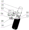
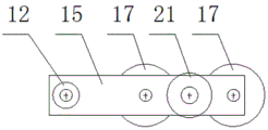
As shown in fig. 4, 5, 10, 11, 12 and 13, in an embodiment of the present invention, the rolling brush assembly includes a rolling brush motor 12, a rolling brush motor mounting seat 51, a rolling brush coupler 52, a rolling brush bearing 56 and a rolling brush 16, the rolling brush motor 12 is mounted on the rolling brush motor mounting seat 51 and is in communication connection with the control system, the rolling brush motor mounting seat 51 is movably connected to the mounting main board 15, the rolling brush coupler 52 is connected to a side of the rolling brush motor mounting seat 51 opposite to the rolling brush motor 12 and is in transmission connection with the rolling brush motor 12, the rolling brush bearing 56 is disposed between the rolling brush coupler 52 and the rolling brush motor mounting seat 51, and the rolling brush 16 is connected to the rolling brush coupler 52. Due to the structural arrangement, the brush head of the rolling brush 16 can be driven to rotate by the rolling brush motor 12 so as to be used for cleaning attachments on the surfaces of the side die 37 and the end die 36 in the segment mould, and meanwhile, the rolling brush 16 can be inclined by the movable rolling brush motor mounting seat 51, so that the attachments on the surfaces of the side die 37 and the end die 36 in the segment mould can be effectively cleaned. Automatic movement of the roller brush 16 in the lateral, longitudinal and vertical directions can also be achieved by the control system. It should be noted that, when the rolling brush assembly is used for cleaning the attached objects on the surface of the side mold 37 in the segment mold, the position of the rolling brush assembly can be adjusted by moving the vertical telescopic column 10 horizontally, longitudinally or vertically, and the inclination angle of the rolling brush 16 is adjusted to reach the same inclination angle of the side mold 37 and the rolling brush 16, so that the bristles of the rolling brush 16 keep a certain contact force with the surface of the side mold 37 and the surface of the end mold 36 to be cleaned, and the control system controls the rolling brush motor 12 to start so as to rotate the brush head of the rolling brush 16, thereby cleaning the attachments on the surfaces of the side mold 37 and the end mold 36.
In the embodiment of the invention, the cleaning device also comprises a rolling brush displacement sliding plate 14, a displacement sliding plate pushing electric cylinder 24 and a rolling brush inclined pushing electric cylinder 18, wherein the displacement sliding plate pushing electric cylinder 24 and the rolling brush inclined pushing electric cylinder 18 are both in communication connection with a control system; the rolling brush displacement sliding plate 14 is movably installed on the installation main plate 15, specifically, the installation main plate 15 is provided with a rolling brush displacement sliding rail 13, the surface of the rolling brush displacement sliding plate 14 facing the installation main plate 15 is provided with a sliding block 28, and the sliding block 28 and the rolling brush displacement sliding rail 13 move in a matching manner, so that the rolling brush displacement sliding plate 14 can move relative to the installation main plate 15. The rolling brush displacement sliding plate 14 is provided with a central shaft lug seat 55, a first electric cylinder lug seat 54 and a second electric cylinder lug seat 53, the rolling brush motor mounting seat 51 is provided with a rotating central shaft 50, and the rotating central shaft 50 is connected with the central shaft lug seat 55; the displacement slide promotes the electric jar 24 and installs on installation mainboard 15, and its expansion end is connected in first electric jar ear seat 54, specifically, is provided with the installation ear seat on the installation mainboard 15, and the stiff end that the displacement slide promoted electric jar 24 is connected with the installation ear seat on the installation mainboard 15, and the expansion end is connected with first electric jar ear seat 54 on the round brush displacement slide 14, and such setting can drive round brush displacement slide 14 and remove for installation mainboard 15 when the displacement slide promotes the telescopic motion of electric jar 24. The fixed end of the electric cylinder 18 is pushed to incline by the rolling brush to be connected to the second electric cylinder lug 53, the movable end of the electric cylinder 18 is pushed to incline by the rolling brush to be connected to the rolling brush motor mounting seat 51 through the electric cylinder shaft pin 49, and the rolling brush 16 of the rolling brush assembly can be driven to incline by the telescopic motion of the electric cylinder 18 pushed to incline by the rolling brush to adjust the inclination angle of the rolling brush 16, so that the side mold 37 and the rolling brush 16 are inclined at the same angle.
It should be noted that, since the electric displacement slide pushing cylinder 24 and the electric rolling brush tilting pushing cylinder 18 are both connected to the control system in communication, the control system can be used to realize the automatic movement of the rolling brush displacement slide 14 and the automatic tilting operation of the rolling brush assembly. Particularly, in the case of the mold in which the side mold 37 is opened at a corner, the distance between the cleaning surface of the side mold 37 and the cleaning surface of the bottom mold 38 is varied, and the bottom mold 38 and the side mold 37 can be cleaned simultaneously by moving the roller brush unit by moving the roller brush displacement slide 14.
As shown in fig. 4, 5, 14 and 15, in an embodiment of the present invention, the cleaning device further includes a node rotation assembly, the node rotation assembly includes a first worm gear reducer 20a, a first worm rotation motor 27a, a second worm gear reducer 20b and a second worm rotation motor 27b, a housing of the first worm gear reducer 20a is mounted on the connecting frame 22a, a housing of the first worm rotation motor 27a is connected with a housing of the first worm gear reducer 20a, and an output shaft of the first worm rotation motor 27a is connected with a worm of the first worm gear reducer 20a, specifically: the output shaft of the first worm rotation motor 27a is connected with the worm of the first worm gear speed reducer 20a through the corner speed reducer, the shell of the second worm gear speed reducer 20b is installed on the installation main board 15, the installation mode can be a screw fixing mode, and the operation is simple and effective; the worm wheel of the second worm and gear speed reducer 20b is connected with the worm wheel of the first worm and gear speed reducer 20a through a connecting assembly, specifically, the connecting assembly comprises a trapezoidal connecting plate 22b and a planar flange, one side of the trapezoidal connecting plate 22b is connected with the worm wheel of the first worm and gear speed reducer 20a, the other side of the trapezoidal connecting plate 22b is connected with the planar flange, and the other side of the planar flange is connected with the worm wheel of the second worm and gear speed reducer 20 b; two parallel trapezoidal connecting plates 22b may optionally be provided. The shell of the second worm rotation motor 27b is connected with the shell of the second worm gear speed reducer 20b, and the output shaft of the second worm rotation motor 27b is connected with the worm of the second worm gear speed reducer 20b, specifically: an output shaft of the second worm rotation motor 27b is connected to the worm of the second worm gear reducer 20b through a coaxial reducer. It should be noted that the worm of the first worm gear-worm speed reducer 20a is fixedly connected with the housing thereof, and the worm gear thereof and the worm thereof can rotate relatively; the worm of the second worm gear-worm speed reducer 20b is fixedly connected with the housing thereof, and the worm wheel thereof and the worm thereof can rotate relatively.
The above-mentioned structure is arranged, when the first worm rotates the motor 27a and rotates, drives the worm wheel of the first worm gear speed reducer 20a and rotates, drives the vertical rotation of trapezoidal connecting plate 22b, causes the planar flange to reach the purpose of slope to drive the worm wheel, the worm and the shell of the second worm gear speed reducer 20b to slope together, and then makes the installation mainboard 15 slope, so alright realize the slope of cleaning device (including dish brush subassembly and round brush subassembly). When the second worm rotation motor 27b rotates, the worm of the second worm gear speed reducer 20b is driven to rotate, and the worm wheel of the second worm gear speed reducer is driven to rotate, at the moment, because the first worm rotation motor 27a does not rotate, and the worm wheel of the second worm gear speed reducer 20b is fixed and does not rotate, the worm of the second worm gear speed reducer 20b can be pushed back to rotate together with the shell, so that the installation main board 15 is driven to horizontally rotate, and therefore the horizontal rotation of the cleaning device (comprising the disc brush assembly and the rolling brush assembly) can be realized.
It can be understood that the node rotating assembly of the invention can realize the inclined and horizontal rotation of the cleaning device in any direction on the horizontal plane, so that the disc brush 17 can be perpendicular to the surface of the bottom die 38 of the segment mould, and the axis of the rolling brush 16 is parallel to the surfaces of the side die 37 and the end die 36 of the segment mould, thereby realizing the purpose of continuous and comprehensive cleaning.
In an optional embodiment of the invention, the automatic duct piece mould cleaning system further comprises a dust removal system for collecting dust generated by the cleaning device during working so as to prevent the dust from polluting air and influencing the health of workers.
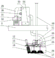
As shown in fig. 16, in the embodiment of the present invention, the dust removing system includes an induced draft fan 31, a hard induced draft tube 29, a soft induced draft tube 35, a filter box 33 and a dust hood 26, the induced draft fan 31 and the filter box 33 are both installed on the cross beam 3 of the truss mechanism, the induced draft fan 31 is in communication connection with the control system, a filter screen is arranged in the filter box 33, a dust hopper 34 is arranged at the bottom of the filter box 33 and used for collecting dust blocked by the filter screen, the dust hood 26 is installed on the installation main board 15 of the cleaning device, an inlet of the filter box 33 is connected with the dust hood opening 25 on the dust hood 26 through the soft induced draft tube 35, an outlet of the filter box 33 is connected with an air inlet of the induced draft fan 31 through the hard induced draft tube 29, and the induced draft fan 31 is provided with an air outlet 32 and used for discharging filtered air. The structure is arranged, dust generated by the cleaning device during operation can be sucked into the filter box 33 through the dust hood 26 and the soft induced air pipe 35 by negative pressure generated by the operation of the draught fan 31, the filter screen blocks the dust in the filter box 33, the dust drops in the dust hopper 34 at the bottom, and the air filtered by the filter screen enters the draught fan 31 through the hard induced air pipe 29 and is discharged from the air outlet 32 of the draught fan 31. The dust in the dust hopper 34 can be periodically cleaned after the cleaning device has been in operation for a period of time.
It should be noted that the control system is in communication connection with the induced draft fan 31, and can control the dust removal system and the cleaning device to work synchronously, when the disc brush 17 and the rolling brush 16 in the cleaning device start cleaning, the dust removal system is started, and when the cleaning stops working, the dust removal system stops working.
Further, in an optional embodiment of the present invention, the dust removal system further includes a dust remover pulse generator 30, the dust remover pulse generator 30 is installed on the truss mechanism, the dust remover pulse generator 30 is communicated with the filter box 33, specifically, a blowback nozzle of the dust remover pulse generator 30 is communicated with the filter box 33 through an air pipe; also, the precipitator pulse generator 30 is in communication with the control system. The dust collector pulse generator 30 uses high-pressure compressed air and adopts a timing pulse reverse blowing method to reversely blow the dust adsorbed on the filter screen into the dust hopper 34, so that the service life of the filter screen can be effectively prolonged. Since the precipitator pulse generator 30 is in communication with the control system, automated operation of the process can be achieved by the control system.
In the embodiment of the invention, the control system mainly comprises a computer, control software, a servo motor controller, a distance measuring sensor and the like. The cleaning of the duct piece mold is a station on an automatic duct piece production line, and when the duct piece mold runs to the station, the duct piece mold needs the mold cleaning operation. The distance measuring sensor is used for measuring the stop position of the pipe piece mold; after the computer collects the data measured by the distance measuring sensor, the computer calculates the deviation between the current stop position of the segment mould and the ideal stop position of the segment mould, and respectively calculates the number of turns and angle data of the rotation required by the transverse walking motor 7, the vertical walking motor 8 and the longitudinal walking motor 9 when the cleaning device runs to the position above the mould for starting cleaning; the computer sends the number of turns and the angle data to the servo motor controller; the servo motor controller controls corresponding servo motors (namely comprising a transverse walking motor 7, a vertical walking motor 8 and a longitudinal walking motor 9) to operate according to the data; the cleaning device is operated to the initial cleaning position above the die, and the cleaning device starts cleaning according to a preset program. According to the longitudinal running speed and position of the cleaning device above the die; determining the vertical running distance and speed of the vertical telescopic column 10; the vertical travel distance and speed are different for different longitudinal positions of the vertical telescopic column 10. The vertical telescopic column 10 designs the longitudinal and vertical running distances and speeds into programs according to the running track of the cleaning device and the longitudinal position of the cleaning device, and the longitudinal and vertical running distances and speeds run according to the programs. The program is changed according to different moulds, and the program is preset in a computer and a servo motor controller in advance. According to the longitudinal position of the cleaning device above the die, the transverse walking motor 7, the vertical walking motor 8, the longitudinal walking motor 9, the first worm rotating motor 27a, the second worm rotating motor 27b, the disc brush motor, the rolling brush motor 12, the displacement sliding plate pushing electric cylinder 24, the rolling brush inclined pushing electric cylinder 18 and the induced draft fan 31 are controlled to act according to a preset program through a computer and a servo motor controller. The electric automatic control system mainly measures the accurate position of the mould on the station, the computer and the servo motor controller move the cleaning device to the initial position of mould cleaning, the corresponding servo motor is controlled to operate through an operation program preset in the computer and the servo motor controller, and the cleaning device is dragged to move along the design track of the program to clean; the cleaning device is controlled by the computer to start cleaning or stop cleaning according to the longitudinal position of the cleaning device.
The automatic cleaning system for the duct piece mold comprises a rolling brush 16 for cleaning a side mold 37 and an end mold 36, and a disc brush 17 for cleaning a bottom mold 38. In operation, the side die 37 is cleaned and the bottom die 38 on the same side is cleaned. The truss drives the cleaning device arranged at the bottom end of the vertical telescopic column 10 to move through an automatic control program of a computer and a servo motor controller, so that the axis of a disc brush 17 of the cleaning device is vertical to the surface of a cleaned mould, the axis of a rolling brush 16 is parallel to the surfaces of a side mould 37 and an end mould 36 of the cleaned mould, and bristle tips are always in contact with the surface to be cleaned with certain force; then the brush head rotates and runs at a constant speed along the curve of the cleaning surface of the die, so that constant-speed and continuous cleaning is realized; and dust generated in the cleaning process is removed through a dust removal system. The whole process realizes full mechanical automatic cleaning.
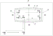
The specific operation of the automatic segment mold sweeping system of the present invention will now be described in detail with reference to fig. 17 and 18, wherein the outer frame line is shown as truss operating range 39 in fig. 17. When the duct piece mold is operated to a cleaning station in a flowing mode through a production line, the duct piece mold needs to be cleaned; a distance measuring sensor measures the stop position of the pipe sheet mould; after the computer collects the data, the computer calculates the deviation between the current stop position of the segment mold and the ideal stop position of the mold; and the data are sent to servo motor controllers of a transverse walking motor 7, a vertical walking motor 8 and a longitudinal walking motor 9, and the number of turns and angle parameters of rotation required for the cleaning device to run to the original parking position are corrected; and starting the operation according to the corrected parameters. The cleaning device starts to move rightwards to the high position (2) from the high position of the parking position (1) (the cleaning device needs to be parked on the upper layer of the pedestrian passageway when not in operation, so that the passage of the passageway is not influenced, namely the high position is reached); moving forwards from the high position (2) to the high position (3); the position (3) is above the mould and in one quarter of the transverse direction of the mould; the cleaning device is rotated by the first worm rotating motor 27a to incline downwards to an angle that the axis of the rolling brush 16 is parallel to the cleaning surface of the left end die 36, and the cleaning device runs leftwards and downwards to the rear end of the left end die 36 at the position (4); the bristle tips of the bristles of the rolling brush 16 are in contact with the cleaning surface of the left side end die 36, a certain force is exerted, the brush heads of the rolling brush 16 and the disc brush 17 rotate simultaneously, and the dust removal system works; cleaning of the left end mold 36 begins. Sweeping forwards at a constant speed to a position (5) along the left end die 36 of the die; the left end die 36 sweep is complete. The cleaning device runs upwards and runs to a high position, the cleaning device is adjusted to be horizontal from an inclined state through the rotation of the first worm rotating motor 27a, and meanwhile, the second worm rotating motor 27b rotates to rotate the cleaning device clockwise by 90 degrees, so that the axis of the disc brush 17 is vertical to the cleaning surface of the bottom die 38; the rolling brush 16 pushes the electric cylinder 24 through the rolling brush inclined electric cylinder 18 and the displacement sliding plate, the axis of the rolling brush 16 is adjusted to be parallel to the cleaning surface of the front side die 37, and the rolling brush runs downwards, so that the bristle tips of the bristles of the rolling brush 16 are in contact with the cleaning surface of the front side die 37; while the tips of the bristles of the disc brush 17 are in contact with the bottom mold 38. The hair tips of the rolling brush 16 and the disc brush 17 and the surface to be cleaned have certain force; and the die runs rightwards along the curve of the bottom surface of the die at a constant speed, and the front side die 37 and the half bottom die 38 are cleaned. During cleaning, the displacement slide plate pushes the electric cylinder 24 to extend and contract, so that the hair tips of the rolling brush 16 and the surface to be cleaned of the front side die 37 always have certain contact force. Cleaning to the position (6); the front side die 37 and the half bottom die 38 are cleaned. The cleaning device runs upwards, runs to a high position, rotates through the first worm rotating motor 27a, inclines downwards until the axis of the rolling brush 16 is parallel to the cleaning surface of the right side end die 36, simultaneously rotates through 90 degrees clockwise by the rotation of the second worm rotating motor 27b, and runs downwards to the front end of the right side end die 36 at the position (6), so that the bristle tips of the bristles of the rolling brush 16 are in contact with the cleaning surface of the right side end die 36 and have certain force; and after the die is cleaned backwards to the position (7) along the right end die 36 at a constant speed, the cleaning of the right end die 36 is completed. The cleaning device is moved upwards to a high position, the cleaning device is adjusted to be horizontal from an inclined state through the rotation of the first worm rotating motor 27a, and meanwhile, the second worm rotating motor 27b rotates to rotate the cleaning device clockwise by 90 degrees; the rolling brush 16 pushes the electric cylinder 24 through the rolling brush inclination electric cylinder 18 and the displacement sliding plate, and the axis of the rolling brush 16 is adjusted to be parallel to the cleaning surface of the side die 37 on the rear side; the downward movement makes the bristle tips of the bristles of the rolling brush 16 contact with the side die 37 at the rear side, meanwhile, the bristle tips of the bristles of the disc brush 17 contact with and are vertical to the bottom die 38, and the bristle tips of the rolling brush 16 and the disc brush 17 have certain contact force with the surface to be cleaned; and the left side runs along the curve of the bottom surface of the mold at a constant speed, and the side mold 37 and the half bottom mold 38 on the rear side are cleaned. When cleaning, the electric cylinder 24 is pushed to stretch by the displacement sliding plate, so that the hair tips of the rolling brush 16 and the surface to be cleaned of the side die 37 at the rear side always have certain contact force, and the cleaning is carried out to a position (4); and (3) cleaning the rear side die 37 and the bottom die 38, stopping the rotation of the three brush heads, stopping the dust remover, and completely cleaning the whole die. The cleaning device moves upwards and moves to a high position. Move to position (3) high-order department to the right, second worm rotates motor 27b and rotates and to clean device anticlockwise rotation 270, moves to position (2) high-order department backward, moves to position (1) high-order department to the left, cleans the mechanism and returns to former parking position, and a cleaning process is accomplished, waits for the next and cleans the circulation.
The above description is only a preferred embodiment of the present invention and is not intended to limit the present invention, and various modifications and changes may be made by those skilled in the art. Any modification, equivalent replacement, or improvement made within the spirit and principle of the present invention should be included in the protection scope of the present invention.