CN115142677A - Building construction template surface clearing device based on multilayer reciprocating brushing mechanism - Google Patents
Building construction template surface clearing device based on multilayer reciprocating brushing mechanism Download PDFInfo
- Publication number
- CN115142677A CN115142677A CN202210737818.6A CN202210737818A CN115142677A CN 115142677 A CN115142677 A CN 115142677A CN 202210737818 A CN202210737818 A CN 202210737818A CN 115142677 A CN115142677 A CN 115142677A
- Authority
- CN
- China
- Prior art keywords
- shell
- bottom end
- device based
- brushing mechanism
- rod
- Prior art date
- Legal status (The legal status is an assumption and is not a legal conclusion. Google has not performed a legal analysis and makes no representation as to the accuracy of the status listed.)
- Pending
Links
Images




Classifications
-
- E—FIXED CONSTRUCTIONS
- E04—BUILDING
- E04G—SCAFFOLDING; FORMS; SHUTTERING; BUILDING IMPLEMENTS OR AIDS, OR THEIR USE; HANDLING BUILDING MATERIALS ON THE SITE; REPAIRING, BREAKING-UP OR OTHER WORK ON EXISTING BUILDINGS
- E04G19/00—Auxiliary treatment of forms, e.g. dismantling; Cleaning devices
- E04G19/006—Cleaning devices
-
- B—PERFORMING OPERATIONS; TRANSPORTING
- B08—CLEANING
- B08B—CLEANING IN GENERAL; PREVENTION OF FOULING IN GENERAL
- B08B1/00—Cleaning by methods involving the use of tools
- B08B1/10—Cleaning by methods involving the use of tools characterised by the type of cleaning tool
- B08B1/12—Brushes
-
- B—PERFORMING OPERATIONS; TRANSPORTING
- B08—CLEANING
- B08B—CLEANING IN GENERAL; PREVENTION OF FOULING IN GENERAL
- B08B1/00—Cleaning by methods involving the use of tools
- B08B1/30—Cleaning by methods involving the use of tools by movement of cleaning members over a surface
-
- B—PERFORMING OPERATIONS; TRANSPORTING
- B08—CLEANING
- B08B—CLEANING IN GENERAL; PREVENTION OF FOULING IN GENERAL
- B08B1/00—Cleaning by methods involving the use of tools
- B08B1/30—Cleaning by methods involving the use of tools by movement of cleaning members over a surface
- B08B1/32—Cleaning by methods involving the use of tools by movement of cleaning members over a surface using rotary cleaning members
-
- B—PERFORMING OPERATIONS; TRANSPORTING
- B08—CLEANING
- B08B—CLEANING IN GENERAL; PREVENTION OF FOULING IN GENERAL
- B08B15/00—Preventing escape of dirt or fumes from the area where they are produced; Collecting or removing dirt or fumes from that area
- B08B15/04—Preventing escape of dirt or fumes from the area where they are produced; Collecting or removing dirt or fumes from that area from a small area, e.g. a tool
-
- B—PERFORMING OPERATIONS; TRANSPORTING
- B08—CLEANING
- B08B—CLEANING IN GENERAL; PREVENTION OF FOULING IN GENERAL
- B08B3/00—Cleaning by methods involving the use or presence of liquid or steam
- B08B3/04—Cleaning involving contact with liquid
Landscapes
- Engineering & Computer Science (AREA)
- Architecture (AREA)
- Mechanical Engineering (AREA)
- Civil Engineering (AREA)
- Structural Engineering (AREA)
- Cleaning In General (AREA)
Abstract
Description
技术领域technical field
本发明涉及建筑施工技术领域,具体来说,涉及一种基于多层往复刷动机构的建筑施工模板表面清除装置。The invention relates to the technical field of building construction, in particular to a building construction template surface cleaning device based on a multi-layer reciprocating brushing mechanism.
背景技术Background technique
建筑模板是一种临时性支护结构,按设计要求制作,使混凝土结构、构件按规定的位置、几何尺寸成形,保持其正确位置,并承受建筑模板自重及作用在其上的外部荷载,进行模板工程的目的,是保证混凝土工程质量与施工安全、加快施工进度和降低工程成本。The building formwork is a temporary supporting structure, which is made according to the design requirements, so that the concrete structure and components are formed according to the specified position and geometric size, maintain their correct position, and bear the self-weight of the building formwork and the external load acting on it. The purpose of the formwork project is to ensure the quality and safety of the concrete project, speed up the construction progress and reduce the project cost.
建筑模板在使用后,其表面会粘附混凝土,需要将其进行清理后才能进行下一次使用,目前在清理建筑模板表面时,需要人工手动刷动建筑模板,劳动强度大,成本高,且刷动的混凝土粉尘会飘扬到空气中,造成粉尘污染,不能在清理时将混凝土粉尘统一收集。After the building formwork is used, its surface will adhere to the concrete, and it needs to be cleaned before it can be used for the next time. At present, when cleaning the surface of the building formwork, it is necessary to manually brush the building formwork manually, which is labor-intensive, high cost, and brushing. The moving concrete dust will fly into the air, causing dust pollution, and the concrete dust cannot be collected uniformly during cleaning.
针对相关技术中的问题,目前尚未提出有效的解决方案。For the problems in the related technologies, no effective solutions have been proposed so far.
发明内容SUMMARY OF THE INVENTION
针对相关技术中的问题,本发明提出一种基于多层往复刷动机构的建筑施工模板表面清除装置,以克服现有相关技术所存在的上述技术问题。In view of the problems in the related art, the present invention proposes a construction template surface cleaning device based on a multi-layer reciprocating brushing mechanism, so as to overcome the above-mentioned technical problems existing in the related art.
为此,本发明采用的具体技术方案如下:For this reason, the concrete technical scheme that the present invention adopts is as follows:
一种基于多层往复刷动机构的建筑施工模板表面清除装置,包括壳体和位于所述壳体底端的刷盘,所述刷盘的底端设有若干均匀分布的刷头,所述壳体的底端开设有滑道,所述滑道内设有与其相匹配的滑块,所述滑块的底端与所述刷盘相连接,所述滑道内一侧设有与所述滑块相连接的往复刷动机构,所述壳体内设有贯穿所述滑块并与所述刷盘相连接的转轴,所述转轴通过传动调节机构与所述滑块相连接;A construction formwork surface removing device based on a multi-layer reciprocating brushing mechanism, comprising a casing and a brush disc at the bottom end of the casing, the bottom end of the brush disc is provided with a number of evenly distributed brush heads, the casing The bottom end of the body is provided with a slideway, the slideway is provided with a sliding block that matches it, the bottom end of the slide block is connected with the brush plate, and one side of the slideway is provided with the sliding block. A reciprocating brushing mechanism connected with blocks, the housing is provided with a rotating shaft that penetrates the sliding block and is connected to the brush disc, and the rotating shaft is connected to the sliding block through a transmission adjustment mechanism;
所述壳体的下方设有对称设置的连接架一和连接架二,所述连接架一和所述连接架二的顶端均对称设有与所述壳体相连接的电动伸缩杆,所述连接架一和所述连接架二相互远离的一侧均设有对称设置的移动轮;A connecting frame 1 and a connecting frame 2 are arranged symmetrically under the casing. The top ends of the connecting frame 1 and the connecting frame 2 are symmetrically provided with electric telescopic rods connected to the casing. A symmetrically arranged moving wheel is provided on the side of the connecting frame 1 and the connecting frame 2 away from each other;
所述往复刷动机构包括位于所述滑道内的托盘,所述托盘的顶端开口设有转盘,所述转盘的轴心处设有L型转轴,所述L型转轴上套设有活动块,所述活动块上开设有与所述L型转轴相匹配的滑槽,所述托盘上设有与所述转盘相连接的伺服电机,所述活动块的两端分别设有竖向设置的推杆和活动杆,所述推杆的顶端与所述滑块相连接,所述推杆和所述活动杆的两侧均设有对称设置的限位转轮,所述限位转轮通过转轴与所述托盘相连接,且所述限位转轮上开设有与所述推杆和所述活动杆相匹配的导向槽。The reciprocating brushing mechanism includes a tray located in the slideway, the top of the tray is opened with a turntable, the axis of the turntable is provided with an L-shaped rotating shaft, and a movable block is sleeved on the L-shaped rotating shaft, The movable block is provided with a chute matching the L-shaped rotating shaft, the tray is provided with a servo motor connected to the turntable, and the two ends of the movable block are respectively provided with vertically arranged pushers. A rod and a movable rod, the top end of the push rod is connected with the slider, both sides of the push rod and the movable rod are provided with symmetrically arranged limit wheels, and the limit wheels pass through the rotating shaft It is connected with the tray, and a guide groove matching with the push rod and the movable rod is opened on the limit runner.
作为优选的,所述传动调节机构包括位于所述滑块顶端的固定壳,所述固定壳内的顶端设有驱动电机,所述驱动电机的输出端设有套设于所述转轴上的轴套,所述轴套的底端开设有与所述转轴相匹配的活动孔,且所述活动孔的内壁环绕设有若干均匀分布的限位槽,所述转轴的外壁环绕设有与所述限位槽相匹配的凸条。Preferably, the transmission adjustment mechanism includes a fixed casing located at the top of the slider, the top of the fixed casing is provided with a driving motor, and the output end of the driving motor is provided with a shaft sleeved on the rotating shaft The bottom end of the shaft sleeve is provided with a movable hole matching the rotating shaft, and the inner wall of the movable hole is surrounded by a number of evenly distributed limit grooves, and the outer wall of the rotating shaft is surrounded with The limit grooves match the convex strips.
作为优选的,所述转轴上套设有连接套,所述连接套的两侧设有对称设置的连接柱,所述固定壳内设有与两组所述连接柱相连接的U型连接架,所述U型连接架上开设有与所述连接柱相匹配的活动槽,所述U型连接架的一侧设有横向设置的衔接杆,所述衔接杆的底端设有液压缸,所述液压缸通过活动轴一分别与所述衔接杆和所述固定壳相连接。Preferably, a connecting sleeve is sleeved on the rotating shaft, symmetrically arranged connecting columns are arranged on both sides of the connecting sleeve, and a U-shaped connecting frame connected to the two groups of the connecting columns is arranged in the fixed shell. , the U-shaped connecting frame is provided with a movable groove that matches the connecting column, one side of the U-shaped connecting frame is provided with a transversely arranged connecting rod, and the bottom end of the connecting rod is provided with a hydraulic cylinder, The hydraulic cylinder is respectively connected with the connecting rod and the fixed shell through a movable shaft.
作为优选的,所述衔接杆的一端设有与所述固定壳相连接的连接轴二,所述壳体的一侧设有倾斜设置的推拉杆,所述推拉杆上设有横向设置的扶手。Preferably, one end of the connecting rod is provided with a connecting shaft 2 connected to the fixed shell, one side of the shell is provided with a push-pull rod arranged obliquely, and a horizontally set handrail is provided on the push-pull rod. .
作为优选的,所述滑槽内的底端开设有与所述活动杆相匹配的弧形槽,且所述托盘的两侧设有与所述滑槽相连接的固定架。Preferably, the bottom end of the chute is provided with an arc-shaped groove matching the movable rod, and two sides of the tray are provided with fixing frames connected with the chute.
作为优选的,所述滑槽内的顶端设有若干与所述滑块相连接的缓冲弹簧,所述活动杆的两侧设有与所述限位转轮相匹配的限位滑道。Preferably, the top end of the chute is provided with a plurality of buffer springs connected with the slider, and the two sides of the movable rod are provided with limit slides matching the limit wheels.
作为优选的,所述壳体的底端设有对称设置的喷头,所述喷头通过软管与位于所述壳体内的水箱相连接。Preferably, the bottom end of the casing is provided with symmetrical spray heads, and the spray heads are connected to the water tank located in the casing through a hose.
作为优选的,所述壳体的底端设有对称设置的吸附头,所述吸附头通过导管与位于所述壳体内的吸尘器相连接。Preferably, the bottom end of the casing is provided with a symmetrically arranged suction head, and the suction head is connected to the vacuum cleaner located in the casing through a conduit.
作为优选的,所述壳体的顶端开口设有盖板,所述盖板通过卡扣与所述壳体相连接。Preferably, the top opening of the casing is provided with a cover plate, and the cover plate is connected to the casing through a buckle.
本发明的有益效果为:通过电动伸缩杆带动壳体上下运动,从而带动刷盘和刷头上下运动,使刷头端部紧密贴合建筑模板顶部,然后滑块随着往复刷动机构在滑槽左右滑动,使刷头刷除建筑模板表面的杂质,刷头转动刷除建筑模板表面的杂质,同时,推动壳体进行移动,可以全面的刷掉建筑模板表面的灰尘,对建筑模板表面的灰尘进行多重刷动,使建筑模板表面清理干净,节省人力,操作方便;而传动调节机构的设计,带动刷盘进行旋转,且能够再次调节刷盘的高度,使得刷头与建筑模板之间更贴合,确保可以把表面的杂质刷掉,保证结构完整性,提高刷动的效率,实用性更强。The beneficial effects of the invention are: the casing is driven up and down by the electric telescopic rod, thereby driving the brush plate and the brush head to move up and down, so that the end of the brush head closely fits the top of the building formwork, and then the slider slides along with the reciprocating brushing mechanism. The groove slides left and right, so that the brush head brushes the impurities on the surface of the building formwork, and the brush head rotates to remove the impurities on the surface of the building formwork. The dust is brushed multiple times to clean the surface of the building formwork, saving manpower and easy operation; and the design of the transmission adjustment mechanism drives the brush disc to rotate, and can adjust the height of the brush disc again, so that the brush head and the building formwork are closer. Fitting ensures that the impurities on the surface can be brushed off, ensuring the structural integrity, improving the efficiency of brushing, and being more practical.
附图说明Description of drawings
为了更清楚地说明本发明实施例或现有技术中的技术方案,下面将对实施例中所需要使用的附图作简单地介绍,显而易见地,下面描述中的附图仅仅是本发明的一些实施例,对于本领域普通技术人员来讲,在不付出创造性劳动的前提下,还可以根据这些附图获得其他的附图。In order to more clearly illustrate the embodiments of the present invention or the technical solutions in the prior art, the accompanying drawings required in the embodiments will be briefly introduced below. Obviously, the drawings in the following description are only some of the present invention. In the embodiments, for those of ordinary skill in the art, other drawings can also be obtained according to these drawings without any creative effort.
图1是根据本发明实施例的一种基于多层往复刷动机构的建筑施工模板表面清除装置的结构示意图;1 is a schematic structural diagram of a construction template surface removing device based on a multi-layer reciprocating brushing mechanism according to an embodiment of the present invention;
图2是根据本发明实施例的一种基于多层往复刷动机构的建筑施工模板表面清除装置中壳体的结构示意图;2 is a schematic structural diagram of a casing in a construction formwork surface removal device based on a multi-layer reciprocating brushing mechanism according to an embodiment of the present invention;
图3是根据本发明实施例的一种基于多层往复刷动机构的建筑施工模板表面清除装置中滑块的俯视图;3 is a top view of a slider in a construction template surface removal device based on a multi-layer reciprocating brushing mechanism according to an embodiment of the present invention;
图4是根据本发明实施例的一种基于多层往复刷动机构的建筑施工模板表面清除装置中往复刷动机构的结构示意图;4 is a schematic structural diagram of a reciprocating brushing mechanism in a construction template surface removal device based on a multi-layered reciprocating brushing mechanism according to an embodiment of the present invention;
图5是根据本发明实施例的一种基于多层往复刷动机构的建筑施工模板表面清除装置中限位转轮的侧视图;5 is a side view of a limiting wheel in a construction formwork surface removing device based on a multi-layer reciprocating brushing mechanism according to an embodiment of the present invention;
图6是根据本发明实施例的一种基于多层往复刷动机构的建筑施工模板表面清除装置中传动调节机构的结构示意图;6 is a schematic structural diagram of a transmission adjustment mechanism in a construction template surface removal device based on a multi-layer reciprocating brushing mechanism according to an embodiment of the present invention;
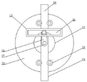
图7是根据本发明实施例的一种基于多层往复刷动机构的建筑施工模板表面清除装置中轴套的仰视图。Fig. 7 is a bottom view of a shaft sleeve in a construction formwork surface cleaning device based on a multi-layer reciprocating brushing mechanism according to an embodiment of the present invention.
图中:In the picture:
1、壳体;2、刷盘;3、刷头;4、滑道;5、滑块;6、往复刷动机构;7、转轴;8、连接架一;9、连接架二;10、电动伸缩杆;11、移动轮;12、托盘;13、转盘;14、L型转轴;15、活动块;16、滑槽;17、伺服电机;18、推杆;19、活动杆;20、限位转轮;21、导向槽;22、固定壳;23、驱动电机;24、轴套;25、活动孔;26、限位槽;27、凸条;28、连接套;29、连接柱;30、U型连接架;31、活动槽;32、衔接杆;33、液压缸;34、连接轴二;35、推拉杆;36、弧形槽;37、固定架;38、缓冲弹簧;39、喷头;40、吸附头;41、盖板。1. Shell; 2. Brush plate; 3. Brush head; 4. Slide; 5. Slider; 6. Reciprocating brushing mechanism; 7. Rotating shaft; 8. Connecting frame one; 9. Connecting frame two; 10. Electric telescopic rod; 11, moving wheel; 12, tray; 13, turntable; 14, L-shaped shaft; 15, movable block; 16, chute; 17, servo motor; 18, push rod; 19, movable rod; 20, Limit wheel; 21, guide groove; 22, fixed shell; 23, drive motor; 24, shaft sleeve; 25, movable hole; 26, limit groove; 27, convex strip; 28, connecting sleeve; 29, connecting column ;30, U-shaped connecting frame; 31, movable groove; 32, connecting rod; 33, hydraulic cylinder; 34, connecting shaft two; 35, push-pull rod; 36, arc groove; 37, fixed frame; 38, buffer spring; 39. Nozzle; 40. Adsorption head; 41. Cover.
具体实施方式Detailed ways
为进一步说明各实施例,本发明提供有附图,这些附图为本发明揭露内容的一部分,其主要用以说明实施例,并可配合说明书的相关描述来解释实施例的运作原理,配合参考这些内容,本领域普通技术人员应能理解其他可能的实施方式以及本发明的优点,图中的组件并未按比例绘制,而类似的组件符号通常用来表示类似的组件。In order to further illustrate the various embodiments, the present invention provides accompanying drawings, which are part of the disclosure of the present invention, and are mainly used to illustrate the embodiments, and can be used in conjunction with the relevant descriptions in the specification to explain the operation principles of the embodiments. For these, those of ordinary skill in the art will understand other possible implementations and the advantages of the present invention. Components in the figures are not drawn to scale, and similar component symbols are generally used to represent similar components.
根据本发明的实施例,提供了一种基于多层往复刷动机构的建筑施工模板表面清除装置。According to an embodiment of the present invention, a surface cleaning device for a building construction formwork based on a multi-layer reciprocating brushing mechanism is provided.
如图1-7所示,根据本发明实施例的基于多层往复刷动机构的建筑施工模板表面清除装置,包括壳体1和位于所述壳体1底端的刷盘2,所述刷盘2的底端设有若干均匀分布的刷头3,所述壳体1的底端开设有滑道4,所述滑道4内设有与其相匹配的滑块5,所述滑块5的底端与所述刷盘2相连接,所述滑道4内一侧设有与所述滑块5相连接的往复刷动机构6,所述壳体1内设有贯穿所述滑块5并与所述刷盘2相连接的转轴7,所述转轴7通过传动调节机构与所述滑块5相连接;As shown in FIGS. 1-7 , the device for removing the surface of a building construction formwork based on a multi-layer reciprocating brushing mechanism according to an embodiment of the present invention includes a housing 1 and a brush disc 2 located at the bottom end of the housing 1 . The brush disc The bottom end of 2 is provided with a number of evenly distributed brush heads 3, the bottom end of the housing 1 is provided with a slideway 4, and the slideway 4 is provided with a matching slider 5, The bottom end is connected with the brush plate 2 , the inner side of the slideway 4 is provided with a reciprocating brushing mechanism 6 connected with the sliding block 5 , and the casing 1 is provided with a penetrating sliding block 5 A rotating shaft 7 connected with the brush plate 2, the rotating shaft 7 is connected with the sliding block 5 through a transmission adjustment mechanism;
所述壳体1的下方设有对称设置的连接架一8和连接架二9,所述连接架一8和所述连接架二9的顶端均对称设有与所述壳体1相连接的电动伸缩杆10,所述连接架一8和所述连接架二9相互远离的一侧均设有对称设置的移动轮11;The lower part of the casing 1 is provided with a connecting frame 1 8 and a connecting frame 2 9 which are symmetrically arranged. In the electric
所述往复刷动机构6包括位于所述滑道4内的托盘12,所述托盘12的顶端开口设有转盘13,所述转盘13的轴心处设有L型转轴14,所述L型转轴14上套设有活动块15,所述活动块15上开设有与所述L型转轴14相匹配的滑槽16,所述托盘12上设有与所述转盘13相连接的伺服电机17,所述活动块15的两端分别设有竖向设置的推杆18和活动杆19,所述推杆18的顶端与所述滑块5相连接,所述推杆18和所述活动杆19的两侧均设有对称设置的限位转轮20,所述限位转轮20通过转轴与所述托盘12相连接,且所述限位转轮20上开设有与所述推杆18和所述活动杆19相匹配的导向槽21。推动本装置至建筑施工模板制作处,将本装置移动至模板上方,根据模板的高度调节电动伸缩杆10的运行长度,启动伺服电机17带动转盘13在托盘12上进行旋转,使得转盘13通过L型转轴14带动活动块15进行上下方向上的往复运动,即可通过活动杆19推拉滑块5在滑槽16内进行往复运动,而限位转轮20的设计,则能够对推杆18和活动杆19提供限位滑道效果,避免出现偏移的情况,刷头3转动刷除建筑模板表面的杂质,同时,推动壳体1进行移动,可以全面的刷掉建筑模板表面的灰尘,对建筑模板表面的灰尘进行多重刷动,使建筑模板表面清理干净,节省人力,操作方便。The reciprocating brushing mechanism 6 includes a
另外,在一个实施例中,如图1-7所示,所述传动调节机构包括位于所述滑块5顶端的固定壳22,所述固定壳22内的顶端设有驱动电机23,所述驱动电机23的输出端设有套设于所述转轴7上的轴套24,所述轴套24的底端开设有与所述转轴7相匹配的活动孔25,且所述活动孔25的内壁环绕设有若干均匀分布的限位槽26,所述转轴7的外壁环绕设有与所述限位槽26相匹配的凸条27,所述转轴7上套设有连接套28,所述连接套28的两侧设有对称设置的连接柱29,所述固定壳22内设有与两组所述连接柱29相连接的U型连接架30,所述U型连接架30上开设有与所述连接柱29相匹配的活动槽31,所述U型连接架30的一侧设有横向设置的衔接杆32,所述衔接杆32的底端设有液压缸33,所述液压缸33通过活动轴一分别与所述衔接杆32和所述固定壳22相连接。启动驱动电机23带动轴套24进行旋转,由于轴套24与转轴7的限位连接关系,使得轴套24在转动的同时带动转轴7进行旋转,进而同步带动刷盘2和刷头3进行旋转,而根据刷头3与建筑模板顶部之间的距离,启动液压缸33带动衔接杆32进行转动,衔接杆32顺时针旋转即可带动刷头3下移,反之,衔接杆32逆时针旋转刷头3上移,衔接杆32在顺时针旋转时带动U型连接架30同步带动,使得U型连接架30通过活动槽31带动连接柱29下移,使得连接柱29通过连接套28带动转轴7同步下移,而转轴7和凸条27则在活动孔25和限位槽26内进行滑动。In addition, in one embodiment, as shown in FIGS. 1-7 , the transmission adjustment mechanism includes a fixed shell 22 located at the top end of the slider 5 , and a
另外,在一个实施例中,如图1-7所示,所述衔接杆32的一端设有与所述固定壳22相连接的连接轴二34,所述壳体1的一侧设有倾斜设置的推拉杆35,所述推拉杆35上设有横向设置的扶手,所述滑槽16内的底端开设有与所述活动杆19相匹配的弧形槽36,且所述托盘12的两侧设有与所述滑槽16相连接的固定架37,所述滑槽16内的顶端设有若干与所述滑块5相连接的缓冲弹簧38,所述活动杆19的两侧设有与所述限位转轮20相匹配的限位滑道。In addition, in one embodiment, as shown in FIGS. 1-7 , one end of the connecting
另外,在一个实施例中,如图1-7所示,所述壳体1的底端设有对称设置的喷头39,所述喷头39通过软管与位于所述壳体1内的水箱相连接,所述壳体1的底端设有对称设置的吸附头40,所述吸附头40通过导管与位于所述壳体1内的吸尘器相连接,所述壳体1的顶端开口设有盖板41,所述盖板41通过卡扣与所述壳体1相连接。通过喷头39的设计可以模板的表面进行喷水打湿,从而 达到降尘的效果,而吸附头40的设计则可对清除过程中产生的杂质进行吸附,提高工作人员的工作环境。In addition, in one embodiment, as shown in FIGS. 1-7 , the bottom end of the housing 1 is provided with symmetrical spray heads 39 , and the spray heads 39 are connected to the water tank located in the housing 1 through a hose. The bottom end of the casing 1 is provided with a symmetrically arranged
为了方便理解本发明的上述技术方案,以下就本发明在实际过程中的工作原理或者操作方式进行详细说明。In order to facilitate the understanding of the above technical solutions of the present invention, the working principle or operation mode of the present invention in the actual process will be described in detail below.
在实际应用时,推动本装置至建筑施工模板制作处,将本装置移动至模板上方,根据模板的高度调节电动伸缩杆10的运行长度,启动驱动电机23带动轴套24进行旋转,由于轴套24与转轴7的限位连接关系,使得轴套24在转动的同时带动转轴7进行旋转,进而同步带动刷盘2和刷头3进行旋转,而根据刷头3与建筑模板顶部之间的距离,启动液压缸33带动衔接杆32进行转动,衔接杆32顺时针旋转即可带动刷头3下移,反之,衔接杆32逆时针旋转刷头3上移,衔接杆32在顺时针旋转时带动U型连接架30同步带动,使得U型连接架30通过活动槽31带动连接柱29下移,使得连接柱29通过连接套28带动转轴7同步下移,而转轴7和凸条27则在活动孔25和限位槽26内进行滑动,即可达到调节刷盘2的上下高度,然后启动伺服电机17带动转盘13在托盘12上进行旋转,使得转盘13通过L型转轴14带动活动块15进行上下方向上的往复运动,即可通过活动杆19推拉滑块5在滑槽16内进行往复运动,而限位转轮20的设计,则能够对推杆18和活动杆19提供限位滑道效果,避免出现偏移的情况。In practical application, push the device to the place where the building construction template is made, move the device to the top of the template, adjust the running length of the electric
综上所述,借助于本发明的上述技术方案,通过电动伸缩杆10带动壳体1上下运动,从而带动刷盘2和刷头3上下运动,使刷头3端部紧密贴合建筑模板顶部,然后滑块5随着往复刷动机构6在滑槽16左右滑动,使刷头3刷除建筑模板表面的杂质,刷头3转动刷除建筑模板表面的杂质,同时,推动壳体1进行移动,可以全面的刷掉建筑模板表面的灰尘,对建筑模板表面的灰尘进行多重刷动,使建筑模板表面清理干净,节省人力,操作方便;而传动调节机构的设计,带动刷盘2进行旋转,且能够再次调节刷盘2的高度,使得刷头3与建筑模板之间更贴合,确保可以把表面的杂质刷掉,保证结构完整性,提高刷动的效率,实用性更强。To sum up, with the help of the above technical solutions of the present invention, the casing 1 is driven to move up and down by the electric
以上所述仅为本发明的较佳实施例而已,并不用以限制本发明,凡在本发明的精神和原则之内,所作的任何修改、等同替换、改进等,均应包含在本发明的保护范围之内。The above descriptions are only preferred embodiments of the present invention, and are not intended to limit the present invention. Any modification, equivalent replacement, improvement, etc. made within the spirit and principle of the present invention shall be included in the scope of the present invention. within the scope of protection.
Claims (9)
Priority Applications (1)
| Application Number | Priority Date | Filing Date | Title |
|---|---|---|---|
| CN202210737818.6A CN115142677A (en) | 2022-06-28 | 2022-06-28 | Building construction template surface clearing device based on multilayer reciprocating brushing mechanism |
Applications Claiming Priority (1)
| Application Number | Priority Date | Filing Date | Title |
|---|---|---|---|
| CN202210737818.6A CN115142677A (en) | 2022-06-28 | 2022-06-28 | Building construction template surface clearing device based on multilayer reciprocating brushing mechanism |
Publications (1)
| Publication Number | Publication Date |
|---|---|
| CN115142677A true CN115142677A (en) | 2022-10-04 |
Family
ID=83408326
Family Applications (1)
| Application Number | Title | Priority Date | Filing Date |
|---|---|---|---|
| CN202210737818.6A Pending CN115142677A (en) | 2022-06-28 | 2022-06-28 | Building construction template surface clearing device based on multilayer reciprocating brushing mechanism |
Country Status (1)
| Country | Link |
|---|---|
| CN (1) | CN115142677A (en) |
Cited By (1)
| Publication number | Priority date | Publication date | Assignee | Title |
|---|---|---|---|---|
| CN115502119A (en) * | 2022-10-19 | 2022-12-23 | 芜湖海格力斯起重机械制造有限公司 | Gantry crane track cleaning device |
Citations (9)
| Publication number | Priority date | Publication date | Assignee | Title |
|---|---|---|---|---|
| FR2685225A1 (en) * | 1991-12-19 | 1993-06-25 | Heulin Entr | Machine for brushing and rubbing down metal panels used for concrete formwork in the erection of buildings |
| CN205509957U (en) * | 2016-03-16 | 2016-08-24 | 潘江如 | Small -size solar panel cleaning device |
| CN208261370U (en) * | 2018-04-04 | 2018-12-21 | 云南亚通电力工程有限公司 | A kind of photovoltaic board cleaning device |
| CN208542598U (en) * | 2018-06-01 | 2019-02-26 | 重庆市亚客喜科技开发有限公司 | A kind of toilet with biological scenery |
| CN109834066A (en) * | 2019-04-04 | 2019-06-04 | 南通巨大机械制造有限公司 | A kind of cleaning machine convenient for adjusting cleaning assemblies |
| CN209958774U (en) * | 2019-04-16 | 2020-01-17 | 山东天衢建筑科技有限公司 | Cleaning and brushing device for aluminum alloy formwork erecting construction |
| CN112060332A (en) * | 2020-09-21 | 2020-12-11 | 汪旺 | Concrete mixing device convenient to clean for constructional engineering |
| CN112627524A (en) * | 2020-12-08 | 2021-04-09 | 潘章林 | Building construction template surface clearing device based on multilayer reciprocating brushing mechanism |
| CN114197872A (en) * | 2021-12-02 | 2022-03-18 | 福建高全建材科技有限公司 | A kind of aluminum template cleaning device |
-
2022
- 2022-06-28 CN CN202210737818.6A patent/CN115142677A/en active Pending
Patent Citations (9)
| Publication number | Priority date | Publication date | Assignee | Title |
|---|---|---|---|---|
| FR2685225A1 (en) * | 1991-12-19 | 1993-06-25 | Heulin Entr | Machine for brushing and rubbing down metal panels used for concrete formwork in the erection of buildings |
| CN205509957U (en) * | 2016-03-16 | 2016-08-24 | 潘江如 | Small -size solar panel cleaning device |
| CN208261370U (en) * | 2018-04-04 | 2018-12-21 | 云南亚通电力工程有限公司 | A kind of photovoltaic board cleaning device |
| CN208542598U (en) * | 2018-06-01 | 2019-02-26 | 重庆市亚客喜科技开发有限公司 | A kind of toilet with biological scenery |
| CN109834066A (en) * | 2019-04-04 | 2019-06-04 | 南通巨大机械制造有限公司 | A kind of cleaning machine convenient for adjusting cleaning assemblies |
| CN209958774U (en) * | 2019-04-16 | 2020-01-17 | 山东天衢建筑科技有限公司 | Cleaning and brushing device for aluminum alloy formwork erecting construction |
| CN112060332A (en) * | 2020-09-21 | 2020-12-11 | 汪旺 | Concrete mixing device convenient to clean for constructional engineering |
| CN112627524A (en) * | 2020-12-08 | 2021-04-09 | 潘章林 | Building construction template surface clearing device based on multilayer reciprocating brushing mechanism |
| CN114197872A (en) * | 2021-12-02 | 2022-03-18 | 福建高全建材科技有限公司 | A kind of aluminum template cleaning device |
Cited By (2)
| Publication number | Priority date | Publication date | Assignee | Title |
|---|---|---|---|---|
| CN115502119A (en) * | 2022-10-19 | 2022-12-23 | 芜湖海格力斯起重机械制造有限公司 | Gantry crane track cleaning device |
| CN115502119B (en) * | 2022-10-19 | 2023-08-15 | 芜湖海格力斯起重机械制造有限公司 | Gantry crane track cleaning device |
Similar Documents
| Publication | Publication Date | Title |
|---|---|---|
| CN100569398C (en) | Program controlled reciprocating dust absorbing, barrier clearing device with automatic guiding function | |
| CN116653094A (en) | A prefabricated staircase mold cleaning device | |
| CN113309350B (en) | Template cleaning device for constructional engineering and cleaning method thereof | |
| CN219378268U (en) | Dust collecting equipment is used in production of infrared germanium-based film | |
| CN212120912U (en) | Little train track cleaning device | |
| CN205765350U (en) | A kind of door lines burr removal device | |
| CN218589976U (en) | Sack cleaning device of sack cleaner | |
| CN110103147B (en) | Machine tool for machining aluminum alloy pipe and working method of machine tool | |
| CN108914852B (en) | A kind of commutation road-surface cleaning apparatus | |
| CN209579134U (en) | Grinding and cleaning machine for H-shaped steel components | |
| CN219747314U (en) | Wall equipment of polishing of decoration fitment | |
| CN114618811B (en) | Automatic cleaning machine for glass greenhouse ceiling | |
| CN216084177U (en) | Novel LED display screen of mining automatic deashing | |
| CN218775356U (en) | Foam engraver dust cleaning device | |
| CN211332503U (en) | Intelligent high-rotating-speed ground polishing machine | |
| CN221761382U (en) | A device for recycling and cleaning wooden formwork for building concrete | |
| CN116512400A (en) | Surface roughening device for PC laminated plate | |
| CN218962111U (en) | Dust collection device convenient to clean for processing superhard wear-resistant material | |
| CN115284148A (en) | Automatic rust cleaning equipment for steel structure surface | |
| CN219960507U (en) | A solar panel cleaning device | |
| CN223001207U (en) | A corrugating machine with convenient cleaning of corrugating rollers | |
| CN218026833U (en) | Knitted fabric dust removal device | |
| CN223891847U (en) | Glass cleaning machine tool | |
| CN220132714U (en) | Groover with dust fall structure | |
| CN221755571U (en) | A high-efficiency steel burr removal device |
Legal Events
| Date | Code | Title | Description |
|---|---|---|---|
| PB01 | Publication | ||
| PB01 | Publication | ||
| SE01 | Entry into force of request for substantive examination | ||
| SE01 | Entry into force of request for substantive examination | ||
| RJ01 | Rejection of invention patent application after publication |
Application publication date: 20221004 |
|
| RJ01 | Rejection of invention patent application after publication |