CN113976285A - Concrete waste recycling system for building - Google Patents
Concrete waste recycling system for building Download PDFInfo
- Publication number
- CN113976285A CN113976285A CN202111291196.0A CN202111291196A CN113976285A CN 113976285 A CN113976285 A CN 113976285A CN 202111291196 A CN202111291196 A CN 202111291196A CN 113976285 A CN113976285 A CN 113976285A
- Authority
- CN
- China
- Prior art keywords
- wall
- crushing
- frame
- sleeved
- conveying
- Prior art date
- Legal status (The legal status is an assumption and is not a legal conclusion. Google has not performed a legal analysis and makes no representation as to the accuracy of the status listed.)
- Withdrawn
Links
Images


Classifications
-
- B—PERFORMING OPERATIONS; TRANSPORTING
- B02—CRUSHING, PULVERISING, OR DISINTEGRATING; PREPARATORY TREATMENT OF GRAIN FOR MILLING
- B02C—CRUSHING, PULVERISING, OR DISINTEGRATING IN GENERAL; MILLING GRAIN
- B02C21/00—Disintegrating plant with or without drying of the material
-
- B—PERFORMING OPERATIONS; TRANSPORTING
- B02—CRUSHING, PULVERISING, OR DISINTEGRATING; PREPARATORY TREATMENT OF GRAIN FOR MILLING
- B02C—CRUSHING, PULVERISING, OR DISINTEGRATING IN GENERAL; MILLING GRAIN
- B02C1/00—Crushing or disintegrating by reciprocating members
- B02C1/02—Jaw crushers or pulverisers
- B02C1/06—Jaw crushers or pulverisers with double-acting jaws
-
- B—PERFORMING OPERATIONS; TRANSPORTING
- B02—CRUSHING, PULVERISING, OR DISINTEGRATING; PREPARATORY TREATMENT OF GRAIN FOR MILLING
- B02C—CRUSHING, PULVERISING, OR DISINTEGRATING IN GENERAL; MILLING GRAIN
- B02C23/00—Auxiliary methods or auxiliary devices or accessories specially adapted for crushing or disintegrating not provided for in preceding groups or not specially adapted to apparatus covered by a single preceding group
- B02C23/08—Separating or sorting of material, associated with crushing or disintegrating
- B02C23/10—Separating or sorting of material, associated with crushing or disintegrating with separator arranged in discharge path of crushing or disintegrating zone
-
- B—PERFORMING OPERATIONS; TRANSPORTING
- B02—CRUSHING, PULVERISING, OR DISINTEGRATING; PREPARATORY TREATMENT OF GRAIN FOR MILLING
- B02C—CRUSHING, PULVERISING, OR DISINTEGRATING IN GENERAL; MILLING GRAIN
- B02C23/00—Auxiliary methods or auxiliary devices or accessories specially adapted for crushing or disintegrating not provided for in preceding groups or not specially adapted to apparatus covered by a single preceding group
- B02C23/18—Adding fluid, other than for crushing or disintegrating by fluid energy
- B02C23/24—Passing gas through crushing or disintegrating zone
- B02C23/30—Passing gas through crushing or disintegrating zone the applied gas acting to effect material separation
-
- B—PERFORMING OPERATIONS; TRANSPORTING
- B02—CRUSHING, PULVERISING, OR DISINTEGRATING; PREPARATORY TREATMENT OF GRAIN FOR MILLING
- B02C—CRUSHING, PULVERISING, OR DISINTEGRATING IN GENERAL; MILLING GRAIN
- B02C4/00—Crushing or disintegrating by roller mills
- B02C4/02—Crushing or disintegrating by roller mills with two or more rollers
- B02C4/08—Crushing or disintegrating by roller mills with two or more rollers with co-operating corrugated or toothed crushing-rollers
-
- B—PERFORMING OPERATIONS; TRANSPORTING
- B08—CLEANING
- B08B—CLEANING IN GENERAL; PREVENTION OF FOULING IN GENERAL
- B08B15/00—Preventing escape of dirt or fumes from the area where they are produced; Collecting or removing dirt or fumes from that area
- B08B15/04—Preventing escape of dirt or fumes from the area where they are produced; Collecting or removing dirt or fumes from that area from a small area, e.g. a tool
-
- B—PERFORMING OPERATIONS; TRANSPORTING
- B09—DISPOSAL OF SOLID WASTE; RECLAMATION OF CONTAMINATED SOIL
- B09B—DISPOSAL OF SOLID WASTE
- B09B3/00—Destroying solid waste or transforming solid waste into something useful or harmless
-
- Y—GENERAL TAGGING OF NEW TECHNOLOGICAL DEVELOPMENTS; GENERAL TAGGING OF CROSS-SECTIONAL TECHNOLOGIES SPANNING OVER SEVERAL SECTIONS OF THE IPC; TECHNICAL SUBJECTS COVERED BY FORMER USPC CROSS-REFERENCE ART COLLECTIONS [XRACs] AND DIGESTS
- Y02—TECHNOLOGIES OR APPLICATIONS FOR MITIGATION OR ADAPTATION AGAINST CLIMATE CHANGE
- Y02W—CLIMATE CHANGE MITIGATION TECHNOLOGIES RELATED TO WASTEWATER TREATMENT OR WASTE MANAGEMENT
- Y02W30/00—Technologies for solid waste management
- Y02W30/50—Reuse, recycling or recovery technologies
- Y02W30/58—Construction or demolition [C&D] waste
Abstract
The invention discloses a concrete waste recycling system for buildings, which relates to the field of waste concrete and aims at solving the problems of different sizes of recycled aggregates formed after crushing, re-crushing and low working efficiency in the prior art. According to the invention, the concrete blocks can be crushed and then crushed to obtain more uniform aggregate, the crushing effect is improved, dust generated during crushing can be collected, the dust is prevented from floating in the outside air, the environmental friendliness is improved, the aggregate can be separated while being conveyed, the practicability is improved, the coarse aggregate and the fine aggregate can be further screened, and the screening effect is improved.
Description
Technical Field
The invention relates to the technical field of waste concrete, in particular to a recycling treatment system for concrete waste for buildings.
Background
Concrete waste, namely, waste concrete, when carrying out the disintegration construction to the building, can produce a large amount of waste concrete, at this moment, can carry out recovery processing to waste concrete and recycle, wherein concrete piece and silt behind the crushing screening can regard as the regeneration of concrete, thick, the fine aggregate, a large amount of miropowder can directly be as the raw materials of cement, the concrete that regenerated cement and regenerated aggregate were prepared can get into next circulation, in whole circulation process, the discarded object realizes the zero release, waste such as concrete among the building rubbish, cement can be used for replacing stone production lawn brick after reasonable crushing, the screening, smash, tens of environmental protection bricks such as stone production lawn brick, square brick, blind hole brick, the brick that permeates water, the wall brick, the module changes, insulating brick, building block brick.
The first procedure of the recycled concrete is crushing, waste concrete blocks are crushed into aggregates with a certain size, and the crushed recycled aggregates are different in size, so that the aggregates with different particle sizes are separated for standby application, and the aggregates with overlarge particle sizes are crushed again, so that the working efficiency is low.
Disclosure of Invention
The invention aims to solve the defects in the prior art and provides a recycling and treating system for concrete waste for buildings.
In order to achieve the purpose, the invention adopts the following technical scheme:
a concrete waste recycling and treating system for buildings comprises a crushing mechanism, wherein the crushing mechanism comprises a crushing box, a feed hopper welded on the inner wall of the top of the crushing box and two extrusion components, each extrusion component comprises two hydraulic cylinders respectively connected on the inner wall of one side of the crushing box through bolts, a fixed plate welded on the inner wall of the bottom of the crushing box, two connecting blocks respectively welded on the outer wall of one end of a piston rod of each hydraulic cylinder, fixed rods with two ends respectively connected on the inner walls of two sides of the crushing box through bearings, an extrusion plate sleeved on the outer wall of the fixed rods and two connecting pieces respectively welded on the outer wall of one side of the extrusion plate;
the crushing mechanism comprises a crushing frame connected to the outer wall of the bottom of the crushing box through bolts, two filter screens and two transmission assemblies, wherein the two filter screens are respectively arranged on two sides of the crushing frame;
the dust removal device comprises a crushing frame, an air inlet frame, a dust collection box, a dust conveying pipe, a top cover, a suction fan, a connecting pipe and dust screens, wherein the outer wall of one side of the crushing frame is connected with the air inlet frame through a bolt, the outer wall of the other side of the crushing frame is connected with an air outlet frame through a bolt, the outer wall of one side of the crushing box is provided with a dust removal mechanism, the dust removal mechanism comprises the dust collection box, the dust conveying pipe, the top cover, the suction fan, the connecting pipe and the dust screens, the dust conveying pipe is connected to the inner wall of the upper portion of one side of the dust collection box in a sleeved mode, the top cover is connected to the outer wall of the top of the dust collection box through a bolt, the suction fan is connected to the outer wall of the top cover in a sleeved mode, and the dust screens are connected to the inner walls of the two sides of the dust collection box through bolts respectively;
the conveying mechanism comprises a conveying piece connected to the outer wall of the bottom of the crushing frame through a bolt, a conveying shaft with one end connected to the inner wall of one side of the conveying piece through a bearing, a spiral blade welded to the outer wall of the conveying shaft, a first motor connected to the outer wall of one end of the top of the conveying piece through a bolt and an installation block welded to the outer wall of the top of the conveying piece and in an L-shaped structure, wherein the outer wall of the top of the installation block is connected with a second motor through a bolt;
carry a bottom to be equipped with screening mechanism, screening mechanism including cup joint in carrying a screening frame on the outer wall, cup joint the discharging pipe on screening frame bottom one end outer wall, locate the fan on one side of screening frame and weld the water conservancy diversion piece on the one end inner wall of keeping away from the discharging pipe in screening frame bottom.
Preferably, two mounting ports are formed in the outer wall of one side of each fixed plate, the two hydraulic oil cylinders are respectively sleeved in the two mounting ports, each connecting piece comprises two hinged blocks, each connecting block is hinged to the outer wall of the corresponding side of the corresponding hinged block, a channel is formed in the inner wall, located between the two fixed plates, of the bottom of the crushing box, and ventilation ports distributed at equal intervals are formed in the inner walls, located on the two sides of the channel, of the bottom of the crushing box.
Preferably, the outer walls of the two sides of the crushing frame are provided with mounting holes, the two filter screens are embedded in the two mounting holes respectively, one end of the transmission shaft and one end of the driven shaft are connected to the outer wall of one side of the crushing frame through bearings respectively, the outer wall of one end of the transmission shaft is sleeved with a first driven wheel, and the outer wall of one end of the driven shaft is sleeved with a second driven wheel.
Preferably, the outer wall of one side of the air inlet frame is provided with air inlets distributed at equal intervals, and the outer wall of one side of the air outlet frame is provided with a fixed port.
Preferably, one end of the dust conveying pipe is sleeved in a fixing port on the air outlet frame, a fixing hole is formed in the inner wall of the upper portion of one side of the dust collection box, one end of the connecting pipe is slidably sleeved in the fixing hole, a flange plate is sleeved on the outer wall of one end of the bottom of the connecting pipe, and the connecting pipe is connected to the outer wall of one side of the dust collection box through a bolt.
Preferably, it has the hourglass material hole that the equidistance distributes to open on the inner wall of transport piece bottom, and has opened the discharge gate on the one end inner wall of transport piece bottom, carry a shaft one end to pass through the bearing and connect on the outer wall of transport piece one side, and has cup jointed driven pulley on carrying a shaft one end outer wall, the belt pulley has been cup jointed on the outer wall of first motor output shaft one end, and the belt pulley passes through the belt and forms the transmission cooperation with driven pulley.
Preferably, the outer wall of one end of the output shaft of the second motor is sleeved with a driving wheel, the driving wheel forms transmission fit with one of the first driven wheels through a belt, the driving wheel forms transmission fit with the other first driven wheel through a belt of an '∞' shaped structure, one of the first driven wheels forms transmission fit with the second driven wheel below the first driven wheel through the belt, and the other first driven wheel forms transmission fit with the other second driven wheel through the belt.
Preferably, the overlap joint of discharging pipe top is on carrying a bottom outer wall, and discharging pipe position and the discharge gate position looks adaptation on carrying the piece, discharging pipe internal diameter size and discharge gate internal diameter size looks adaptation, and the discharging pipe is opened on being located the outer wall in the screening frame and is had the screening hole that the equidistance distributes, it has the through-hole to open on one side outer wall of screening frame, and the fan inlays the dress in the through-hole, it has the discharge opening to open on the one end inner wall that screening frame bottom is close to the water conservancy diversion piece.
Preferably, all weld on the four corners outer wall of screening frame bottom has the support column, and all weld on the outer wall of four support column bottoms has the supporting seat of round platform form, and equal fixedly connected with blotter on the outer wall of four supporting seat bottoms, and all be equipped with the non-slip raised that the equidistance distributes on the outer wall of four blotter bottoms.
The invention has the beneficial effects that:
1. the crushing mechanism and the crushing mechanism are arranged, waste concrete blocks are placed between the two extrusion plates through the feed hopper, four hydraulic cylinders are started, piston rods of the hydraulic cylinders move to drive the two extrusion plates to do circular motion along the fixed rods, the concrete blocks are further crushed, the crushed concrete blocks fall between the two transmission assemblies, the crushing teeth on the two first crushing rollers, the second crushing rollers and the two second crushing rollers can crush the concrete blocks, the concrete blocks can be crushed and then crushed, aggregate with uniform particle size can be obtained, and the crushing effect is improved;
2. the dust removal mechanism is arranged, the suction fan is started, dust generated when the concrete block is crushed is conveyed into the dust collection box by the suction fan, and is deposited in the dust collection box under the filtering action of the dust screen, so that the dust generated during crushing can be collected, the dust is prevented from floating in the external air, and the environmental protection property is improved;
3. the conveying part is provided with a material leaking hole and a material discharging hole, under the conveying of the spiral blade, aggregate with smaller particles enters the screening frame through the material leaking hole, aggregate with larger particles enters the material discharging pipe through the material discharging hole, and the aggregate can be separated while being conveyed, so that the practicability is improved;
4. be provided with screening frame and fan, start the fan, the flabellum of fan rotates and blows on one side outer wall of water conservancy diversion piece with the fine aggregate on the inner wall of screening frame bottom, and then through the discharge opening and collect, and the flabellum of fan is in the pivoted for thoughtlessly in the coarse aggregate fine aggregate advance the screening frame through screening hole and carrying, can carry out further screening to coarse, fine aggregate, improved the screening effect.
Drawings
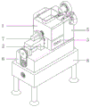
FIG. 1 is a schematic perspective view of a construction concrete waste recycling system according to the present invention;
FIG. 2 is a schematic side view of a concrete waste recycling system for construction according to the present invention;
FIG. 3 is a schematic cross-sectional three-dimensional structure diagram of a crushing mechanism of a recycling treatment system for waste concrete for construction according to the present invention;
FIG. 4 is a schematic perspective view of an extrusion assembly of a recycling system for waste concrete for construction according to the present invention;
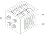
FIG. 5 is a schematic perspective view of a crushing mechanism of the recycling system for waste concrete for construction according to the present invention;
FIG. 6 is a schematic cross-sectional perspective view of a crushing mechanism of a recycling system for waste concrete for construction according to the present invention;
FIG. 7 is a schematic cross-sectional three-dimensional structure view of a dust removing mechanism of a concrete waste recycling system for construction according to the present invention;
FIG. 8 is a schematic cross-sectional perspective view of a conveying mechanism of a recycling system for waste concrete for construction according to the present invention;
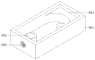
fig. 9 is a schematic perspective view of a screening mechanism of a recycling system for waste concrete for construction according to the present invention.
In the figure: 1 crushing mechanism, 101 crushing box, 102 feeding hopper, 11 extruding component, 111 hydraulic oil cylinder, 112 fixing plate, 113 connecting block, 114 fixing rod, 115 extruding plate, 116 connecting piece, 2 crushing mechanism, 201 crushing frame, 202 filter screen, 21 transmission component, 211 transmission shaft, 212 driven shaft, 213 first crushing roller, 214 second crushing roller, 215 crushing teeth, 3 air inlet frame, 4 air outlet frame, 5 dust removing mechanism, 501 dust collecting box, 502 dust conveying pipe, 503 top cover, 504 suction fan, 505 connecting pipe, 506 dust screen, 6 conveying mechanism, 601 conveying piece, 602 conveying shaft, 603 spiral blade, 604 first motor, 605 mounting block, 7 second motor, 8 screening mechanism, 801 screening frame, 802 discharging pipe, 803 fan and 804 guide block.
Detailed Description
The technical solutions in the embodiments of the present invention will be clearly and completely described below with reference to the drawings in the embodiments of the present invention, and it is obvious that the described embodiments are only a part of the embodiments of the present invention, and not all of the embodiments.
the outer wall of one side of the fixed plate 112 is provided with two mounting ports, the two hydraulic oil cylinders 111 are respectively sleeved in the two mounting ports, the connecting piece 116 comprises two hinged blocks, the connecting block 113 is respectively hinged on the outer wall of the opposite side of the two hinged blocks, the inner wall of the bottom of the crushing box 101, which is positioned between the two fixed plates 112, is provided with a channel, and the inner walls of the bottom of the crushing box 101, which are positioned at the two sides of the channel, are provided with ventilation ports which are distributed equidistantly;
the crushing mechanism 2 comprises a crushing frame 201 connected to the outer wall of the bottom of the crushing box 101 through bolts, two filter screens 202 and two transmission assemblies 21 which are respectively arranged at two sides of the crushing frame 201, each transmission assembly 21 comprises a transmission shaft 211 with one end connected to the inner wall of one side of the crushing frame 201 through a bearing, a driven shaft 212 with one end connected to one side of the crushing frame 201 through a bearing and positioned on the inner wall obliquely below the transmission shaft 211, a first crushing roller 213 sleeved on the outer wall of the transmission shaft 211, a second crushing roller 214 sleeved on the outer wall of the driven shaft 212 and a plurality of crushing teeth 215 which are respectively welded on the outer walls of the first crushing roller 213 and the second crushing roller 214, and a second motor 7 is connected to the outer wall of the top of the mounting block 605 through bolts;
mounting holes are formed in the outer walls of two sides of the crushing frame 201, the two filter screens 202 are respectively embedded in the two mounting holes, one ends of a transmission shaft 211 and a driven shaft 212 are respectively connected to the outer wall of one side of the crushing frame 201 through bearings, a first driven wheel is sleeved on the outer wall of one end of the transmission shaft 211, and a second driven wheel is sleeved on the outer wall of one end of the driven shaft 212;
the driving wheel is sleeved on the outer wall of one end of an output shaft of the second motor 7, the driving wheel forms transmission fit with one of the first driven wheels through a belt, the driving wheel forms transmission fit with the other first driven wheel through a belt of an infinity-shaped structure, one of the first driven wheels forms transmission fit with the second driven wheel below the oblique through the belt, and the other first driven wheel forms transmission fit with the other second driven wheel through the belt.
The concrete blocks can be crushed and then crushed, aggregate with uniform particle size can be obtained, and the crushing effect is improved.
one end of the dust conveying pipe 502 is sleeved in a fixing port on the air outlet frame 4, a fixing hole is formed in the inner wall of the upper portion of one side of the dust collection box 501, one end of the connecting pipe 505 is slidably sleeved in the fixing hole, a flange plate is sleeved on the outer wall of one end of the bottom of the connecting pipe 505, and the connecting pipe 505 is connected to the outer wall of one side of the dust collection box 501 through a bolt.
Can collect the dust that produces when smashing, avoid the dust to fly away in the external air, improve the feature of environmental protection.
Example 3, referring to fig. 8, a concrete waste recycling system for construction, a conveying mechanism 6 includes a conveying member 601 connected to the bottom outer wall of a crushing frame 201 by bolts, a conveying shaft 602 connected to one side inner wall of the conveying member 601 by a bearing at one end, a screw blade 603 welded to the outer wall of the conveying shaft 602, a first motor 604 connected to the outer wall of one end of the top of the conveying member 601 by bolts, and a mounting block 605 welded to the outer wall of the top of the conveying member 601 in an "L" shape;
the inner wall of the bottom of the conveying part 601 is provided with material leaking holes distributed equidistantly, the inner wall of one end of the bottom of the conveying part 601 is provided with a material discharging hole, one end of the conveying shaft 602 is connected to the outer wall of one side of the conveying part 601 through a bearing, the outer wall of one end of the conveying shaft 602 is sleeved with a driven belt pulley, the outer wall of one end of an output shaft of the first motor 604 is sleeved with a belt pulley, and the belt pulley is in transmission fit with the driven belt pulley through a belt.
Can separate the aggregate while conveying, and improve the practicability.
the position of the discharge pipe 802 is matched with the position of a discharge hole on the conveying piece 601, the inner diameter of the discharge pipe 802 is matched with the inner diameter of the discharge hole, screening holes which are distributed at equal intervals are formed in the outer wall of the discharge pipe 802 positioned in the screening frame 801, a through hole is formed in the outer wall of one side of the screening frame 801, the fan 803 is embedded in the through hole, and a discharge hole is formed in the inner wall of one end, close to the flow guide block 804, of the bottom of the screening frame 801;
all weld on the four corners outer wall of screening frame 801 bottom has the support column, all welds the supporting seat that has the round platform form on four support column bottom outer walls, and equal fixedly connected with blotter on four supporting seat bottom outer walls all is equipped with the non-slip raised that the equidistance distributes on four blotter bottom outer walls.
Can further sieve thick, fine aggregate, improve the screening effect.
Waste concrete blocks are placed between two extrusion plates 115 through a feed hopper 102, four hydraulic oil cylinders 111 are started, piston rods of the hydraulic oil cylinders 111 move to drive the two extrusion plates 115 to do circular motion along a fixed rod 114, the concrete blocks are further crushed, the crushed concrete blocks fall between two transmission assemblies 21, crushing teeth 215 on two first crushing rollers 213, the second crushing rollers 214 and the two second crushing rollers 214 can crush the concrete blocks, a suction fan 504 is started, the suction fan 504 conveys dust generated when the concrete blocks are crushed into a dust collection box 501, under the filtering action of a dust screen 506, the dust is deposited in the dust collection box 501, under the conveying action of a helical blade 603, aggregates with smaller particles enter a screening frame 801 through a material leakage hole, aggregates with larger particles enter a material discharge pipe 802 through a material discharge hole, and a fan 803 is started, the flabellum of fan 803 rotates and blows the fine aggregate on the inner wall of screening frame 801 bottom on one side outer wall of water conservancy diversion piece 804, and then passes through the discharge opening and collects, and the flabellum of fan 803 is when the pivoted for the fine aggregate that thoughtlessly has in the coarse aggregate passes through the screening hole and carries into in the screening frame 801.
The present invention is not limited to the above-described embodiments, and various changes can be made within the knowledge of those skilled in the art without departing from the gist of the present invention, and the contents of the changes still fall within the scope of the present invention.
Claims (9)
1. The concrete waste recycling and treating system for the building comprises a crushing mechanism (1) and is characterized in that the crushing mechanism (1) comprises a crushing box (101), a feed hopper (102) welded on the inner wall of the top of the crushing box (101) and two extrusion assemblies (11), wherein each extrusion assembly (11) comprises two hydraulic cylinders (111) respectively connected to the inner wall of one side of the crushing box (101) through bolts, a fixing plate (112) welded on the inner wall of the bottom of the crushing box (101), two connecting blocks (113) respectively welded on the outer wall of one end of a piston rod of each hydraulic cylinder (111), fixing rods (114) with two ends respectively connected to the inner walls of two sides of the crushing box (101) through bearings, an extrusion plate (115) sleeved on the outer wall of the fixing rod (114) and two connecting pieces (116) respectively welded on the outer wall of one side of the extrusion plate (115);
the crushing device is characterized in that a crushing mechanism (2) is arranged on the outer wall of the bottom of the crushing box (101), the crushing mechanism (2) comprises a crushing frame (201) connected to the outer wall of the bottom of the crushing box (101) through bolts, two filter screens (202) arranged on two sides of the crushing frame (201) respectively and two transmission assemblies (21), each transmission assembly (21) comprises a transmission shaft (211) with one end connected to the inner wall of one side of the crushing frame (201) through a bearing, a driven shaft (212) with one end connected to one side of the crushing frame (201) through a bearing and positioned on the inner wall obliquely below the transmission shaft (211), a first crushing roller (213) sleeved on the outer wall of the transmission shaft (211), a second crushing roller (214) sleeved on the outer wall of the driven shaft (212) and a plurality of crushing teeth (215) welded to the outer walls of the first crushing roller (213) and the second crushing roller (214) respectively;
the dust removing device is characterized in that an air inlet frame (3) is connected to the outer wall of one side of the crushing frame (201) through a bolt, an air outlet frame (4) is connected to the outer wall of the other side of the crushing frame (201) through a bolt, a dust removing mechanism (5) is arranged on the outer wall of one side of the crushing box (101) through a bolt, the dust removing mechanism (5) comprises a dust collecting box (501) connected to the outer wall of one side of the crushing box (101) through a bolt, a dust conveying pipe (502) sleeved on the inner wall of the upper portion of one side of the dust collecting box (501), a top cover (503) connected to the outer wall of the top of the dust collecting box (501) through a bolt, a suction fan (504) connected to the outer wall of the top cover (503) through a bolt, a connecting pipe (505) sleeved on the outer wall of the air inlet end of the suction fan (504), and dust screens (506) connected to the inner walls of the two sides of the dust collecting box (501) through bolts respectively;
the bottom of the crushing frame (201) is provided with a conveying mechanism (6), the conveying mechanism (6) comprises a conveying part (601) connected to the outer wall of the bottom of the crushing frame (201) through a bolt, a conveying shaft (602) with one end connected to the inner wall of one side of the conveying part (601) through a bearing, a spiral blade (603) welded to the outer wall of the conveying shaft (602), a first motor (604) connected to the outer wall of one end of the top of the conveying part (601) through a bolt and an installation block (605) welded to the outer wall of the top of the conveying part (601) and having an L-shaped structure, and the outer wall of the top of the installation block (605) is connected with a second motor (7) through a bolt;
carry a (601) bottom to be equipped with screening mechanism (8), screening mechanism (8) are including cup jointing screening frame (801) on carrying a (601) outer wall, cup jointing discharging pipe (802) on screening frame (801) bottom one end outer wall, locating fan (803) on one side of screening frame (801) and welding in a water conservancy diversion piece (804) on the one end inner wall of discharging pipe (802) is kept away from in screening frame (801) bottom.
2. The concrete waste recycling system for building as claimed in claim 1, wherein two mounting openings are opened on the outer wall of one side of the fixing plate (112), and two hydraulic cylinders (111) are respectively sleeved in the two mounting openings, the connecting member (116) comprises two hinged blocks, and the connecting block (113) is respectively hinged on the outer wall of the opposite side of the two hinged blocks, the inner wall of the bottom of the crushing box (101) between the two fixing plates (112) is opened with a channel, and the inner walls of the bottom of the crushing box (101) at two sides of the channel are opened with ventilation openings distributed equidistantly.
3. The concrete waste recycling system for buildings according to claim 1, wherein the outer walls of both sides of the crushing frame (201) are provided with mounting holes, the two filter screens (202) are respectively embedded in the two mounting holes, one end of the transmission shaft (211) and one end of the driven shaft (212) are respectively connected to the outer wall of one side of the crushing frame (201) through bearings, the outer wall of one end of the transmission shaft (211) is sleeved with a first driven wheel, and the outer wall of one end of the driven shaft (212) is sleeved with a second driven wheel.
4. The recycling system of concrete waste for construction according to claim 1, wherein the outer wall of one side of the air inlet frame (3) is provided with air inlets distributed at equal intervals, and the outer wall of one side of the air outlet frame (4) is provided with a fixing port.
5. The recycling system of concrete waste for construction as claimed in claim 4, wherein one end of said dust pipe (502) is sleeved in a fixing hole on the air outlet frame (4), a fixing hole is opened on the inner wall of the upper portion of one side of said dust box (501), one end of said connecting pipe (505) is slidably sleeved in the fixing hole, a flange is sleeved on the outer wall of one end of the bottom of said connecting pipe (505), and said connecting pipe (505) is connected to the outer wall of one side of said dust box (501) by bolts.
6. The recycling system of concrete waste for construction as claimed in claim 1, wherein said conveying member (601) has material leaking holes distributed at equal intervals on the inner wall of the bottom, and a material discharging hole is arranged on the inner wall of one end of the bottom of the conveying member (601), one end of said conveying shaft (602) is connected to the outer wall of one side of the conveying member (601) through a bearing, and a driven pulley is sleeved on the outer wall of one end of the conveying shaft (602), and a pulley is sleeved on the outer wall of one end of the output shaft of said first motor (604), and the pulley forms a driving fit with the driven pulley through a belt.
7. The recycling system for concrete waste materials for building of claim 3, characterized in that the outer wall of one end of the output shaft of the second motor (7) is sleeved with a driving wheel, the driving wheel forms transmission fit with one of the first driven wheels through a belt, the driving wheel forms transmission fit with the other first driven wheel through a belt of an "∞" shaped structure, one of the first driven wheels forms transmission fit with the second driven wheel below the slope through a belt, and the other first driven wheel forms transmission fit with the other second driven wheel through a belt.
8. The concrete waste recycling system for building as claimed in claim 6, wherein the top end of the discharging pipe (802) is connected to the outer wall of the bottom of the conveying member (601), the position of the discharging pipe (802) is matched with the position of the discharging port on the conveying member (601), the inner diameter of the discharging pipe (802) is matched with the inner diameter of the discharging port, the outer wall of the discharging pipe (802) in the screening frame (801) is provided with screening holes distributed at equal intervals, the outer wall of one side of the screening frame (801) is provided with through holes, the fan (803) is embedded in the through holes, and the inner wall of one end of the bottom of the screening frame (801) close to the diversion block (804) is provided with a discharging hole.
9. The recycling system for concrete waste materials for building as claimed in claim 1, wherein the outer walls of four corners of the bottom of said screening frame (801) are welded with supporting columns, the outer walls of bottom ends of four supporting columns are welded with truncated cone-shaped supporting seats, the outer walls of bottom of four supporting seats are fixedly connected with cushions, and the outer walls of bottom of four cushions are provided with anti-skid protrusions distributed equidistantly.
Priority Applications (1)
| Application Number | Priority Date | Filing Date | Title |
|---|---|---|---|
| CN202111291196.0A CN113976285A (en) | 2021-11-03 | 2021-11-03 | Concrete waste recycling system for building |
Applications Claiming Priority (1)
| Application Number | Priority Date | Filing Date | Title |
|---|---|---|---|
| CN202111291196.0A CN113976285A (en) | 2021-11-03 | 2021-11-03 | Concrete waste recycling system for building |
Publications (1)
| Publication Number | Publication Date |
|---|---|
| CN113976285A true CN113976285A (en) | 2022-01-28 |
Family
ID=79745968
Family Applications (1)
| Application Number | Title | Priority Date | Filing Date |
|---|---|---|---|
| CN202111291196.0A Withdrawn CN113976285A (en) | 2021-11-03 | 2021-11-03 | Concrete waste recycling system for building |
Country Status (1)
| Country | Link |
|---|---|
| CN (1) | CN113976285A (en) |
Cited By (1)
| Publication number | Priority date | Publication date | Assignee | Title |
|---|---|---|---|---|
| CN115625183A (en) * | 2022-09-21 | 2023-01-20 | 北京山水之光园林工程有限公司 | Gardens organic waste processing system |
-
2021
- 2021-11-03 CN CN202111291196.0A patent/CN113976285A/en not_active Withdrawn
Cited By (1)
| Publication number | Priority date | Publication date | Assignee | Title |
|---|---|---|---|---|
| CN115625183A (en) * | 2022-09-21 | 2023-01-20 | 北京山水之光园林工程有限公司 | Gardens organic waste processing system |
Similar Documents
| Publication | Publication Date | Title |
|---|---|---|
| CN111545290A (en) | Sorting device is retrieved to building rubbish | |
| CN109900107B (en) | Movable construction waste recycling device and using method | |
| CN210097897U (en) | Building solid waste in-situ recycling treatment device | |
| CN113413958A (en) | Preparation system and preparation method of recycled fine aggregate self-compacting concrete | |
| CN212791327U (en) | Waste concrete recycling device | |
| CN113426809A (en) | Building rubbish recycling device | |
| CN110982575B (en) | Biomass granular fuel forming machine for new energy | |
| CN112756047A (en) | Mechanical equipment for preparing regenerated sand stone material by utilizing building garbage particles | |
| CN109894186B (en) | Construction waste recycling and crushing treatment equipment and use method | |
| CN113976285A (en) | Concrete waste recycling system for building | |
| CN211329766U (en) | Waste material shredding device for civil construction | |
| CN212348892U (en) | Concrete crushing aggregate powder separator | |
| CN117065853A (en) | Highway bridge precast beam slab concrete waste material processing apparatus | |
| CN112705313A (en) | Construction waste masonry garbage treatment device and implementation method thereof | |
| CN112169977A (en) | Municipal building waste circulating crushing device and using method thereof | |
| CN214556171U (en) | Construction waste treatment device for building engineering | |
| CN114950683A (en) | Construction waste coarse aggregate recycling device | |
| CN212328437U (en) | A reducing mechanism for rubbish is recycled | |
| CN113333098A (en) | Impurity removal and separation device and separation method for construction waste recycled aggregate | |
| CN207143071U (en) | A kind of sludge solidification screens collection machine | |
| CN114588991B (en) | Gravel smashing device for urban road construction | |
| CN219723103U (en) | Building rubbish recycled concrete reducing mechanism | |
| CN218108358U (en) | High-efficient sand sieve separator | |
| CN215611875U (en) | Building rubbish recovery processing collection device for building engineering | |
| CN218486160U (en) | Building aggregate processing separator box |
Legal Events
| Date | Code | Title | Description |
|---|---|---|---|
| PB01 | Publication | ||
| PB01 | Publication | ||
| SE01 | Entry into force of request for substantive examination | ||
| SE01 | Entry into force of request for substantive examination | ||
| WW01 | Invention patent application withdrawn after publication |
Application publication date: 20220128 |
|
| WW01 | Invention patent application withdrawn after publication |