Irrigation equipment for farming
Technical Field
The invention belongs to the field of agriculture, and particularly relates to an irrigation device for agricultural planting.
Background
Agricultural irrigation mainly refers to irrigation operation performed on agricultural cultivation areas, and can be generally divided into traditional ground irrigation, common spray irrigation and micro-irrigation. Traditional ground irrigation comprises ridge irrigation, furrow irrigation, flood irrigation and flood irrigation, but the irrigation methods usually consume a large amount of water and have low water utilization capacity, so that the traditional ground irrigation is an unreasonable agricultural irrigation method. In addition, the common spray irrigation technology is a relatively common irrigation mode in Chinese agricultural production, but the water utilization efficiency of the common spray irrigation technology is not high.
The modern agricultural micro irrigation technology comprises micro irrigation, drip irrigation, infiltration irrigation and the like, wherein micro irrigation is an irrigation form of spraying water to areas such as branches and leaves of crops by using a refraction, rotation or radiation type micro spray head, belongs to the micro irrigation category, has low working pressure and small flow rate, can increase soil moisture, can improve air humidity, adjusts local microclimate, and is very widely applied; drip irrigation is an irrigation form of uniformly and slowly dripping water into soil near a crop root zone drop by drop arrows, water droppers, drip irrigation tapes or other orifice type irrigators arranged on capillary tubes, and is one of the most water-saving and effective irrigation ways due to small dripping flow and slow infiltration and mainly by means of diffusion under the action of tension of the capillary tubes. Meanwhile, accurate fertilization can be performed through the head fertilizing device, and low investment and high income are really achieved. The irrigation technologies have good water-saving performance and higher water utilization rate than the traditional irrigation mode, and certainly, have some disadvantages.
Disclosure of Invention
The irrigation device for agricultural planting aims to solve the existing problems and comprises a pipeline, a valve and a stirring device; the pipeline comprises a main pipeline, water outlet pipelines and branch pipes are respectively arranged on two sides of the main pipeline, a first water outlet pipeline and a second water outlet pipeline are installed on one side of the main pipeline, the first water outlet pipeline is communicated with a first water outlet arranged on the side surface of a reservoir, a filter screen is installed at the position of the first water outlet, a first valve is arranged between the first water outlet pipeline and the reservoir, a movable sieve plate is detachably installed at the position 2cm away from the upper edge inside the reservoir, a water level monitor is installed on the surface of the outer side of the reservoir, a water storage port is arranged below the same side of the water level monitor, the water storage port is communicated with the output end of a water pump through a pipeline, a second valve is arranged on the pipeline, a second water outlet arranged on the other side surface of the reservoir is communicated with a stirring pool through a pipeline, a third valve is, the surface of the movable baffle is provided with a filter screen, a stirring device is arranged above the stirring tank, the stirring device comprises a base, a supporting rod is vertically arranged above the base, one side of the supporting rod is fixed with a stirring controller, the upper end of the supporting rod is rotatably provided with a cross rod, the lower end of the cross rod is fixed with a stirring rod, the stirring rod enters the stirring tank through a feeding hole formed in the upper surface of the stirring tank, the stirring tank is arranged at the upper end inside the batching tank, the outer side surface of the batching tank opposite to the stirring device is provided with a water outlet which is communicated with a second water outlet pipeline to flow to the main pipeline, a fourth valve is arranged between the second water outlet pipeline and the main pipeline, a plurality of branch pipes are arranged on the other side of the batching tank, the branch pipes are in a three-dimensional square shape and comprise main pipeline branch pipes and, drip and irrigate branch pipe and be close to trunk line 2cm department installation fifth valve, drip and irrigate branch pipe side and connect a plurality of capillary, the dripper pipe is connected to the capillary below, spout and irrigate the stay tube of branch pipe through radial perpendicular to trunk line top fixed, lay in the crop top, stay tube and spout and irrigate the branch pipe and install sixth valve, spout the downside fixed surface slide of irrigating the branch pipe, the slide lower surface sets up electronic slide rail, electronic slide rail passes through the pulley cooperation with the shower nozzle and is connected, the pulley is fixed in the upper portion of shower nozzle, the shower nozzle is connected with the one end of plastic hose, the other end of plastic hose is through the connecting pipe with spout and irrigate branch pipe intercommunication, the shower nozzle is for turning to the shower nozzle.
Furthermore, a movable upper cover is arranged above the reservoir, the upper cover can be opened to naturally store water when raining, and the upper cover is closed when water is full.
Furthermore, the capillary is arranged from a position 4cm away from the main pipeline, is an elastic hard plastic pipe, has the diameter of 13-16mm, has the same length as the plant, and is spaced by 25-40 cm.
Furthermore, the dropper pipe is an elastic hard plastic pipe, one end of the dropper pipe is embedded into the capillary, and the other end of the dropper pipe is placed beside the main stem of the plant.
Furthermore, the slide is a hollow cuboid without a bottom, and is equal in length to the irrigation branch pipes in the same direction.
Furthermore, set up vegetation state sensor in the planting district soil of stating this kind of irrigation equipment installation to lay the cable with all kinds of valves, stirring controller, water level detector carry out electric connection, through PLC control.
The invention has the beneficial effects that: the invention realizes drip irrigation, spray irrigation, pesticide spraying and liquid fertilizer spraying through one device. The working pressure is low during sprinkling irrigation, the flow is small, the soil moisture can be increased, the air humidity can be improved, and the local microclimate can be adjusted; when in drip irrigation, water is dripped into soil near a crop root area uniformly and slowly drop by drop through a dropper pipe arranged on a capillary, the drip flow is small, the water slowly infiltrates, the water is mainly diffused by the tension action of the capillary, the irrigation method is one of the most water-saving and effective irrigation methods, the water is locally and accurately irrigated, the utilization rate of the water is greatly improved, the weed breeding is reduced, the soil structure is improved, and the requirement on the water source pressure is reduced. Simultaneously this device can also realize the configuration and the spraying of pesticide and fertilizer through the cooperation of spouting irrigation branch pipe and stirring pond and corresponding valve, really accomplishes low input, high income, has also alleviateed farming person's work load, has improved irrigation efficiency for the growth state of crops can in time be detected, and the growth demand can be satisfied, provides important supplementary for the good growth of crops.
Drawings
The invention is described in further detail below with reference to the figures and specific embodiments.
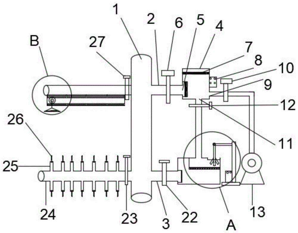
FIG. 1 is a schematic view showing the construction of an irrigation device for agricultural planting according to the present invention;
FIG. 2 is an enlarged schematic view of portion A of FIG. 1;
FIG. 3 is an enlarged schematic view of portion B of FIG. 1;
fig. 4 is a schematic connection diagram of support tubes, irrigation branches, drip branches, and main tubes.
In the figure: 1. a main pipeline; 2. a first outlet conduit; 3. a second outlet conduit; 4. a reservoir; 5. a first water outlet; 6. a first valve; 7. a movable sieve plate; 8. a water level monitor; 9. a water storage port; 10. a second valve; 11. a second water outlet; 12. a third valve; 13. a water pump; 14. a movable baffle; 15. a base; 16. a support bar; 17. a cross bar; 18. a stirring rod; 19. a stirring controller; 20. a stirring tank; 21. a dosing tank; 22. a fourth valve; 23. a fifth valve; 24. drip irrigation branch pipes; 25. a capillary; 26. a dropper tube; 27. a sixth valve; 28. spraying and irrigating branch pipes; 29. a slideway; 30. an electric slide rail; 31. a pulley; 32. a plastic hose; 33. a spray head; 34. a feed inlet; 35. and (5) supporting the tube.
Detailed Description
The technical solutions in the embodiments of the present invention will be clearly and completely described below with reference to the drawings in the embodiments of the present invention, and it is obvious that the described embodiments are only a part of the embodiments of the present invention, and not all of the embodiments. All other embodiments, which can be derived by a person skilled in the art from the embodiments given herein without making any creative effort, shall fall within the protection scope of the present invention.
As shown in fig. 1-4, the irrigation device for agricultural planting comprises a pipeline, a valve and a stirring device; the pipeline comprises a main pipeline 1, water outlet pipelines and branch pipes are respectively arranged on two sides of the main pipeline 1, a first water outlet pipeline 2 and a second water outlet pipeline 3 are installed on one side of the main pipeline 1, the first water outlet pipeline 2 is communicated with a first water outlet 5 arranged on the side surface of a reservoir 4, a filter screen is installed at the position of the first water outlet 5, a first valve 6 is arranged between the first water outlet pipeline 2 and the reservoir 4, a movable upper cover is installed above the reservoir 4, a movable sieve plate 7 is detachably installed at the position 2cm away from the upper edge inside the reservoir 4, a water level monitor 8 is installed on the surface of the outer side of the reservoir 4, a water storage port 9 is arranged below the same side of the water level monitor 8, the water storage port 9 is communicated with the output end of a water pump 13 through a pipeline, a second valve 10 is arranged on the pipeline, and a second water outlet 11, a third valve 12 is arranged between the second water outlet 11 and the stirring tank 20, a movable baffle 14 is installed at the bottom of the stirring tank 20, a filter screen is arranged on the surface of the movable baffle 14, a stirring device is arranged above the stirring tank 20 and comprises a base 15, a supporting rod 16 is vertically arranged above the base 15, a stirring controller 19 is fixed on one side of the supporting rod 16 and is in signal connection with the stirring device, a cross rod 17 is rotatably installed at the upper end of the supporting rod 16, a stirring rod 18 is fixed at the lower end of the cross rod 17, the stirring rod 18 enters the stirring tank 20 through a feed inlet 34 formed in the upper surface of the stirring tank 20, the stirring tank 20 is arranged at the upper end inside a proportioning tank 21, a water outlet is formed in the outer side surface of the proportioning tank 21 opposite to the stirring device and is communicated with a second water outlet pipeline 3 to flow into a main pipeline 1, and a fourth valve 22 is, the other side of the main pipeline 1 is provided with a plurality of branch pipes which are three-dimensional and square, the branch pipes comprise a drip irrigation branch pipe 24 and a spray irrigation branch pipe 28, the drip irrigation branch pipe 24 is directly and transversely communicated with the main pipeline 1 and is contacted with the ground, the drip irrigation branch pipe 24 is provided with a fifth valve 23 at a position which is close to the main pipeline 1 and is about 2cm, the side surface of the drip irrigation branch pipe 24 is provided with a plurality of capillary pipes 25, the capillary pipes 25 are arranged from a position which is about 4cm away from the main pipeline 1, the capillary pipes 25 are elastic hard plastic pipes, the diameter of the capillary pipes is 13-16mm, the length of the capillary pipes is equal to that of the plants, the interval between every two capillary pipes 25 is 25-40cm, the lower part of each capillary pipe 25 is connected with a drip tube 26, the drip tube 26 is an elastic hard plastic pipe, one end of each drip tube 26 is embedded into the corresponding capillary pipe 25, the other end of the, lay in the crop top, sixth valve 27 is installed with spouting and irrigating branch pipe 28 to stay tube 35, spout and irrigate branch pipe 28's downside surface fixed slide 29, slide 29 is the hollow cuboid that does not have the bottom, and with spout and irrigate branch pipe 28 syntropy isometric, slide 29 lower surface sets up electronic slide rail 30 and inside is the cavity, electronic slide rail 30 is connected through the pulley 31 cooperation with shower nozzle 33, pulley 31 is fixed in the upper portion of shower nozzle 33, shower nozzle 33 is connected with the one end of plastic hose 32, the other end of plastic hose 32 is through connecting pipe and spout and irrigate branch pipe 28 intercommunication, shower nozzle 33 can turn to automatically, states to set up plant growth state sensor in the planting district soil of this kind of irrigation equipment installation to lay the cable with all kinds of valves, stirring controller 19, water level monitor 8 carry out electric connection, through PLC control.
The working principle and the mode of the invention are as follows: detecting the growth state of plants through a plant growth state sensor of the plants during planting, setting a water storage mode and an irrigation mode according to the types, water shortage degrees, fertilizer shortage and insect damage of the plants through PLC analysis, when a water level monitor 8 detects that the water level in a reservoir is lower than a first water outlet 5, a second valve 10 is opened, the other valves are closed, the water storage water level is increased to a preset value, when the detected plants need root irrigation, a first valve 6 and a fifth valve 23 are opened, the second valve 10, a third valve 12, a fourth valve 22 and a sixth valve 27 are all in a closed state, water flows out from a first water outlet pipeline 2 according to set flow rate and flow, and the water flows through a main pipeline 1, passes through a drip irrigation branch pipe 24 and then carries out fixed drip irrigation on crops through a capillary 25 and a drip irrigation pipe 26; when the measured plant needs to be irrigated in a large range, the first valve 6 and the sixth valve 27 are opened, the other valves are closed, the electric slide rail 30 is started, and the spray head 33 performs direction-changing spraying irrigation according to a preset spraying range; when detecting that the crops are damaged by insects or lack of fertilizer, the PLC sets corresponding pesticides or fertilizers and corresponding proportions, ingredients are put in from the feeding port 34, the third valve 12 is opened, the other valves are in a closed state, the ingredients flow to the stirring tank 20 according to a preset water volume, the stirring controller 19 is opened, automatic stirring is started according to a preset time, the stirring time is over, the movable baffle 14 is opened, the ingredients enter the ingredients tank 21 and are diluted to a set concentration through water flow, the third valve 12 is closed, the fourth valve 22 and the sixth valve 27 are opened, the other valves are in a closed state, the liquid ingredients flow out through the second water outlet pipeline 3, flow to the supporting pipe 35, flow through the irrigation branch pipe 28, and are sprayed to a target position through the spray head 33 through the plastic hose 32.
In the description herein, references to the description of "one embodiment," "an example," "a specific example" or the like are intended to mean that a particular feature, structure, material, or characteristic described in connection with the embodiment or example is included in at least one embodiment or example of the invention. In this specification, the schematic representations of the terms used above do not necessarily refer to the same embodiment or example. Furthermore, the particular features, structures, materials, or characteristics described may be combined in any suitable manner in any one or more embodiments or examples.
The foregoing is merely exemplary and illustrative of the present invention and various modifications, additions and substitutions may be made by those skilled in the art to the specific embodiments described without departing from the scope of the invention as defined in the accompanying claims.