CN110217547B - Dismounting device for storage battery - Google Patents
Dismounting device for storage battery Download PDFInfo
- Publication number
- CN110217547B CN110217547B CN201910620125.7A CN201910620125A CN110217547B CN 110217547 B CN110217547 B CN 110217547B CN 201910620125 A CN201910620125 A CN 201910620125A CN 110217547 B CN110217547 B CN 110217547B
- Authority
- CN
- China
- Prior art keywords
- plate
- positioning
- discharging
- box body
- electric
- Prior art date
- Legal status (The legal status is an assumption and is not a legal conclusion. Google has not performed a legal analysis and makes no representation as to the accuracy of the status listed.)
- Active
Links
Images


Classifications
-
- B—PERFORMING OPERATIONS; TRANSPORTING
- B23—MACHINE TOOLS; METAL-WORKING NOT OTHERWISE PROVIDED FOR
- B23P—METAL-WORKING NOT OTHERWISE PROVIDED FOR; COMBINED OPERATIONS; UNIVERSAL MACHINE TOOLS
- B23P19/00—Machines for simply fitting together or separating metal parts or objects, or metal and non-metal parts, whether or not involving some deformation; Tools or devices therefor so far as not provided for in other classes
- B23P19/008—Machines for simply fitting together or separating metal parts or objects, or metal and non-metal parts, whether or not involving some deformation; Tools or devices therefor so far as not provided for in other classes the parts being continuously transported through the machine during assembling or disassembling
-
- B—PERFORMING OPERATIONS; TRANSPORTING
- B23—MACHINE TOOLS; METAL-WORKING NOT OTHERWISE PROVIDED FOR
- B23P—METAL-WORKING NOT OTHERWISE PROVIDED FOR; COMBINED OPERATIONS; UNIVERSAL MACHINE TOOLS
- B23P19/00—Machines for simply fitting together or separating metal parts or objects, or metal and non-metal parts, whether or not involving some deformation; Tools or devices therefor so far as not provided for in other classes
- B23P19/04—Machines for simply fitting together or separating metal parts or objects, or metal and non-metal parts, whether or not involving some deformation; Tools or devices therefor so far as not provided for in other classes for assembling or disassembling parts
- B23P19/06—Screw or nut setting or loosening machines
-
- B—PERFORMING OPERATIONS; TRANSPORTING
- B65—CONVEYING; PACKING; STORING; HANDLING THIN OR FILAMENTARY MATERIAL
- B65G—TRANSPORT OR STORAGE DEVICES, e.g. CONVEYORS FOR LOADING OR TIPPING, SHOP CONVEYOR SYSTEMS OR PNEUMATIC TUBE CONVEYORS
- B65G29/00—Rotary conveyors, e.g. rotating discs, arms, star-wheels or cones
-
- B—PERFORMING OPERATIONS; TRANSPORTING
- B65—CONVEYING; PACKING; STORING; HANDLING THIN OR FILAMENTARY MATERIAL
- B65G—TRANSPORT OR STORAGE DEVICES, e.g. CONVEYORS FOR LOADING OR TIPPING, SHOP CONVEYOR SYSTEMS OR PNEUMATIC TUBE CONVEYORS
- B65G47/00—Article or material-handling devices associated with conveyors; Methods employing such devices
- B65G47/74—Feeding, transfer, or discharging devices of particular kinds or types
- B65G47/82—Rotary or reciprocating members for direct action on articles or materials, e.g. pushers, rakes, shovels
-
- H—ELECTRICITY
- H01—ELECTRIC ELEMENTS
- H01M—PROCESSES OR MEANS, e.g. BATTERIES, FOR THE DIRECT CONVERSION OF CHEMICAL ENERGY INTO ELECTRICAL ENERGY
- H01M10/00—Secondary cells; Manufacture thereof
- H01M10/54—Reclaiming serviceable parts of waste accumulators
-
- Y—GENERAL TAGGING OF NEW TECHNOLOGICAL DEVELOPMENTS; GENERAL TAGGING OF CROSS-SECTIONAL TECHNOLOGIES SPANNING OVER SEVERAL SECTIONS OF THE IPC; TECHNICAL SUBJECTS COVERED BY FORMER USPC CROSS-REFERENCE ART COLLECTIONS [XRACs] AND DIGESTS
- Y02—TECHNOLOGIES OR APPLICATIONS FOR MITIGATION OR ADAPTATION AGAINST CLIMATE CHANGE
- Y02W—CLIMATE CHANGE MITIGATION TECHNOLOGIES RELATED TO WASTEWATER TREATMENT OR WASTE MANAGEMENT
- Y02W30/00—Technologies for solid waste management
- Y02W30/50—Reuse, recycling or recovery technologies
- Y02W30/84—Recycling of batteries or fuel cells
Abstract
The invention relates to the field of storage battery recycling, in particular to a dismounting device for a storage battery, which comprises a workbench and a rotary table, wherein a stepping motor is arranged in the workbench, the rotary table is horizontally arranged at the output end of the stepping motor, five positioning jigs which are uniformly distributed along the circumferential direction of the rotary table are arranged on the rotary table, a feeding mechanism, a screw dismounting mechanism, a heating mechanism, a carrying mechanism and a transferring mechanism are sequentially arranged beside the rotary table, a material receiving box is arranged beside the carrying mechanism, a material receiving conveying belt is arranged beside the transferring mechanism, the feeding mechanism comprises a containing box body, a material pushing assembly and a material discharging assembly, a material discharging groove and four supporting legs which are distributed in a rectangular shape are arranged at the bottom of the containing box body, the material pushing assembly is arranged on the containing box body, and the material discharging. The invention realizes the automatic disassembly of the sealing cover from the bottom shell without manual operation, improves the disassembly efficiency and improves the repair utilization rate of the polar plate.
Description
Technical Field
The invention relates to the field of storage battery recovery, in particular to a dismounting device for a storage battery.
Background
With the development of society, the use of lead storage batteries is more and more extensive, the lead storage battery is the battery with the largest yield and the widest application in the world at present, however, the discarded waste lead storage batteries are increased year by year, and the pollution of the batteries is mainly the pollution of heavy metal lead and electrolyte solution. Lead can cause neurasthenia, numbness of limbs, dyspepsia, blood poisoning, and renal injury in nervous system.
At present, the whole battery is out of order and cannot be used under the condition of a plurality of conditions of the waste lead-acid storage battery, but a part of grid monomer structures in the battery are intact, and the grid monomer structures can be completely taken out, processed and then assembled for continuous use. Traditional lead acid battery dismantles adopts the manual work to dismantle the screw that closing cap and drain pan are connected and gets off, then unpacks the separation apart with the drain pan through the instrument with the closing cap, and the manual work is dismantled and is separated closing cap and drain pan although can effectual dismantlement, but has the shortcoming of dismantling efficiency too low. There is also useful slitting saw with drain pan and closing cap involution department cutting separation, but this kind of dismantlement mode produces vibrations easily, and vibrations can cause the grid monomer impaired to cause the pole plate of disassembling of old and useless lead acid battery to reprocess the utilization ratio very low.
Disclosure of Invention
The invention provides a dismounting device for a storage battery, which aims to solve the problems of the background art.
In order to solve the technical problems, the invention provides the following technical scheme:
the utility model provides a dismounting device for battery, includes workstation and carousel, be equipped with step motor in the workstation, the carousel is horizontal installation on step motor's output, be equipped with five along carousel circumference evenly distributed's positioning jig on the carousel, the side of carousel is equipped with feed mechanism, screw in proper order and demolishs mechanism, heating mechanism, is used for dismantling the transport mechanism of closing cap and is used for carrying the transport mechanism of drain pan, the side of transport mechanism is equipped with and connects the magazine, the side of transport mechanism is equipped with and connects the material conveyer belt, feed mechanism is including holding the box body, pushing material subassembly and blowing subassembly, it is equipped with the blown down tank and four supporting legss that are the rectangle and distribute to hold the box body bottom, it installs on holding the box body to push away the material subassembly, the blowing unit mount is on the blown.
Furthermore, the positioning jig comprises a positioning frame body, a pressing plate, a positioning electric push rod, a positioning push plate, two connecting columns with external threads, two springs and two positioning caps, wherein the positioning frame body is fixed on the turntable, one end of the pressing plate is provided with two symmetrically arranged telescopic plates, the positioning frame body is provided with two telescopic grooves which are in one-to-one sliding fit with the two telescopic plates, the two connecting columns are symmetrically arranged on the pressing plate, the two telescopic plates are positioned between the two connecting columns, the positioning frame body is provided with two through holes for the connecting columns to pass through, the two positioning caps are respectively arranged on the two connecting columns, the two springs are respectively sleeved on the two connecting columns, one ends of the two springs are respectively connected on the side walls of the positioning frame body, the other ends of the two springs are respectively connected with one positioning cap, the positioning electric push rod is horizontally, and the output end of the positioning electric push rod is arranged towards the pressure plate, and the positioning push plate is arranged at the output end of the positioning electric push rod.
Further, the material pushing assembly comprises a driving motor, a first chain wheel, a second chain wheel, a screw rod, a balance slide rod and a material pushing piece, two connecting plates which are symmetrically arranged are arranged on the left side wall and the right side wall of the box body, the screw rod is installed on the two connecting plates in a rotating mode, the balance slide rod is installed on the other two connecting plates, a first mounting plate which is horizontally arranged is arranged on the rear side wall of the box body, the driving motor is installed on the first mounting plate, the first chain wheel is installed on the output end of the driving motor, the second chain wheel is installed at one end of the screw rod, the second chain wheel is located right above the first chain wheel, the second chain wheel is connected with the first chain wheel through chain transmission, and a threaded hole matched with the screw rod in a threaded mode and a sliding hole matched with the balance slide rod are formed in.
Further, the discharging component comprises a first discharging plate, a second discharging plate, a discharging motor, a first gear, a second gear and a linkage rod, the first discharging plate and the second discharging plate are arranged in the discharging groove in a spaced and rotating mode, a first protruding rotating shaft is arranged on one end side wall of the first discharging plate, the first gear is arranged on the first protruding rotating shaft, a first driven plate which is vertically arranged upwards is arranged on the first protruding rotating shaft, a second protruding rotating shaft is arranged on the first end side wall of the second discharging plate, a second driven plate which is vertically arranged downwards is arranged on the second protruding rotating shaft, two ends of the linkage rod are respectively and rotatably arranged on the first driven plate and the second driven plate, a second mounting plate which is vertically arranged is arranged on the side wall of the containing box body, the discharging motor is horizontally arranged on the second mounting plate, the second gear is arranged on an output end of the discharging motor, and the second gear is meshed with the first gear.
Further, the screw is demolishd the mechanism and is included first mount table, first lift cylinder, lifter plate, first electric jar, second electric jar and electric screwdriver, and first lift cylinder is the vertical top of installing at first mount table, the lifter plate is installed on the output of first lift cylinder, the bottom at the lifter plate is installed to first electric jar, the second electric jar is installed on the slip table of first electric jar to second electric jar is the cross with first electric jar, be equipped with the U template on the slip table of second electric jar, electric screwdriver is vertical the installation on the U template.
Further, heating mechanism includes second mount table, connecting tube and exhaust box, connecting tube is the vertical top of installing at the second mount table, the exhaust box is the bottom of horizontally connect at connecting tube, the bottom of exhaust box is equipped with the jet-propelled head of a plurality of.
Further, transport mechanism is the same with transport mechanism's structure and all includes third mount table, second lift cylinder, third mounting panel, third electric jar and two gripper, the second lift cylinder is vertical top of installing at the third mount table, the third mounting panel is horizontal installation on the output of second lift cylinder, the top of third mounting panel is equipped with the guide bar that two symmetries set up, be equipped with two and two guide bar one-by-one direction complex guide holder on the third mount table, the bottom at the third mounting panel is installed to the third electric jar, be equipped with the fourth mounting panel that is the U type on the slip table of third electric jar, two grippers are installed respectively at the both ends of fourth mounting panel.
Compared with the prior art, the invention has the beneficial effects that:
firstly, the turntable can be driven to rotate in a stepping mode through the stepping motor, in the rotating process, the storage batteries can be sequentially fed into the corresponding positioning jigs through the feeding mechanism, the positioning jigs can position and fix the storage batteries in the storage batteries, screws connected with the sealing cover and the bottom shell can be automatically removed through the screw removing mechanism, the sealing cover can be heated through the heating mechanism to slightly expand and soften, then the sealing cover is pulled out of the bottom shell through the carrying mechanism and separated, the sealing cover is carried and placed in the material receiving box through the carrying mechanism, and the bottom shell is carried to the material receiving conveying belt through the transferring mechanism.
Secondly, in the feeding process, the storage batteries are firstly loaded into the containing box body, then all the storage batteries in the containing box body are pushed to the discharging groove through the material pushing assembly, the foremost storage battery is supported by the first discharging plate and the second discharging plate, then the discharging motor drives the first gear to rotate in a stepping mode, the first gear drives the second gear and the first discharging plate to rotate synchronously, the first discharging plate is gradually changed into a vertical state from a horizontal state, meanwhile, the first driven plate drives the second driven plate, the second protruding rotating shaft and the second discharging plate to rotate in a stepping mode in the opposite direction through the linkage rod, the included angle between the first discharging plate and the second discharging plate is increased along with the rotation, the storage batteries gradually fall towards the positioning frame body on the first discharging plate and the second discharging plate, and after the first discharging plate and the second discharging plate are both changed into a vertical state, the battery has lost the barrier force, and later the battery just steadily falls into the locating frame in, avoided the battery to fall out from the blown down tank after can not be accurate fall into the positioning jig like this to and avoid the battery to damage.
Drawings
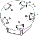
FIG. 1 is a schematic perspective view of the present invention;
FIG. 2 is a perspective view of the table;
FIG. 3 is an enlarged view taken at A in FIG. 2;
FIG. 4 is a first partial schematic view of a feeding mechanism;
FIG. 5 is a second partial schematic view of the feeding mechanism;
FIG. 6 is a perspective view of the screw removal mechanism;
FIG. 7 is a perspective view of the heating mechanism;
FIG. 8 is a perspective view of the handling mechanism;
the reference numbers in the figures are: the device comprises a workbench 1, a turntable 11, a positioning jig 2, a positioning frame 21, a pressing plate 22, a telescopic plate 221, a positioning electric push rod 23, a positioning push plate 231, a connecting column 24, a spring 25, a positioning cap 26, a feeding mechanism 3, an accommodating box body 31, a supporting leg 311, a discharge chute 312, a connecting plate 313, a first mounting plate 314, a material pushing component 32, a driving motor 321, a first chain wheel 322, a second chain wheel 323, a screw rod 324, a balance slide rod 325, a material pushing component 326, a material discharging component 33, a first material discharging plate 331, a first driven plate 3311, a second material discharging plate 332, a second protruding rotating shaft 3321, a second driven plate 3322, a material discharging motor 333, a first gear 334, a second gear 335, a linkage rod 336, a screw removing mechanism 4, a first mounting table 41, a first lifting cylinder 42, a lifting plate 43, a first electric cylinder 44, a second electric cylinder 45, a U-shaped plate 451, an electric screwdriver 46, a heating mechanism 5 and a second mounting table 51, the device comprises a connecting pipeline 52, an exhaust box 53, an air nozzle 54, a carrying mechanism 6, a third mounting table 61, a guide seat 611, a second lifting cylinder 62, a third mounting plate 63, a guide rod 631, a third electric cylinder 64, a fourth mounting plate 641, a mechanical claw 65, a transfer mechanism 7, a material receiving box 8 and a material receiving conveying belt 9.
Detailed Description
In order to make the objects, technical solutions and advantages of the present invention more apparent, the present invention is described in further detail below with reference to the accompanying drawings and embodiments. It should be understood that the specific embodiments described herein are merely illustrative of the invention and are not intended to limit the invention.
In the description of the present invention, it is to be understood that the terms "longitudinal", "lateral", "upper", "lower", "front", "rear", "left", "right", "vertical", "horizontal", "top", "bottom", "inner", "outer", and the like, indicate orientations or positional relationships based on those shown in the drawings, are merely for convenience of description of the present invention, and do not indicate or imply that the referenced devices or elements must have a particular orientation, be constructed and operated in a particular orientation, and thus, are not to be construed as limiting the present invention.
Referring to fig. 1 to 8, a dismounting device for a storage battery comprises a workbench 1 and a turntable 11, wherein a stepping motor is arranged in the workbench 1, the turntable 11 is horizontally mounted on an output end of the stepping motor, five positioning jigs 2 which are uniformly distributed along the circumferential direction of the turntable 11 are arranged on the turntable 11, a feeding mechanism 3, a screw dismounting mechanism 4, a heating mechanism 5, a carrying mechanism 6 for dismounting a sealing cover and a transferring mechanism 7 for carrying a bottom shell are sequentially arranged beside the turntable 11, a material receiving box 8 is arranged beside the carrying mechanism 6, a material receiving conveying belt 9 is arranged beside the transferring mechanism 7, the feeding mechanism 3 comprises a containing box body 31, a material pushing assembly 32 and a material discharging assembly 33, a material discharging groove 312 and four supporting legs 311 which are distributed in a rectangular shape are arranged at the bottom of the containing box body 31, the material pushing assembly 32 is mounted on the containing box body 31, the discharging assembly 33 is arranged on the discharging groove 312; the stepping motor can drive the turntable 11 to rotate in a stepping mode, all the positioning jigs 2 can also rotate synchronously along with the turntable 11, in the rotating process, the pushing assembly 32 can push the storage battery in the containing box body 31 to the discharging groove 312, when the storage battery at the foremost end is positioned at the discharging groove 312, the pushing assembly 32 stops working, then the discharging assembly 33 slowly discharges the storage battery from the discharging groove 312, the storage battery slowly falls into the positioning jig 2, the positioning jig 2 can clamp and fix the storage battery, the screw removing mechanism 4 can automatically remove all screws connected between the sealing cover and the bottom shell, the sealing cover can be heated by the heating mechanism 5, so that the sealing cover slightly expands and softens, the sealing cover can be detached from the bottom shell by the carrying mechanism 6 and carried and placed in the material receiving box 8, can place the drain pan from positioning jig 2 transport on connecing material conveyer belt 9 through transport mechanism 7.
The positioning jig 2 comprises a positioning frame body 21, a pressing plate 22, a positioning electric push rod 23, a positioning push plate 231, two connecting columns 24 with external threads, two springs 25 and two positioning caps 26, the positioning frame body 21 is fixed on the turntable 11, one end of the pressing plate 22 is provided with two expansion plates 221 which are symmetrically arranged, the positioning frame body 21 is provided with two expansion grooves which are in one-to-one sliding fit with the two expansion plates 221, the two connecting columns 24 are symmetrically arranged on the pressing plate 22, the two expansion plates 221 are positioned between the two connecting columns 24, the positioning frame body 21 is provided with two through holes for the connecting columns 24 to pass through, the two positioning caps 26 are respectively arranged on the two connecting columns 24, the two springs 25 are respectively sleeved on the two connecting columns 24, one end of each spring 25 is connected to the side wall of the positioning frame body 21, and the other end of each spring 25 is respectively connected with one, the positioning electric push rod 23 is horizontally arranged on the rotary table 11, the output end of the positioning electric push rod 23 faces the pressure plate 22, and the positioning push plate 231 is arranged at the output end of the positioning electric push rod 23; after the battery falls into location framework 21, location electric putter 23 can drive location push pedal 231 and remove to clamp plate 22, two expansion plates 221 on later clamp plate 22 can the indentation corresponding flexible inslot, meanwhile, two spliced poles 24 and two location caps 26 also can carry out synchronous motion along with clamp plate 22, two springs 25 can become tensile state because of the change of the position of location cap 26, clamp plate 22 fixes the battery firmly in location framework 21 at last, location electric putter 23 removes behind the drive power, clamp plate 22 can get back to initial position through the elastic restoring force of two springs 25.
The pushing assembly 32 comprises a driving motor 321, a first chain wheel 322, a second chain wheel 323, a screw rod 324, a balance slide rod 325 and a pushing piece 326, the left and right side walls of the containing box body 31 are respectively provided with two connecting plates 313 which are symmetrically arranged, the screw rod 324 is rotatably arranged on the two connecting plates 313, the balance slide bar 325 is arranged on the other two connecting plates 313, a first mounting plate 314 horizontally disposed is provided on a rear sidewall of the receiving box body 31, the driving motor 321 is mounted on the first mounting plate 314, the first chain wheel 322 is installed at the output end of the driving motor 321, the second chain wheel 323 is installed at one end of the screw rod 324, and the second chain wheel 323 is positioned right above the first chain wheel 322, the second chain wheel 323 is connected with the first chain wheel 322 by chain transmission, the material pushing part 326 is provided with a threaded hole in threaded fit with the screw rod 324 and a sliding hole in sliding fit with the balance sliding rod 325; the driving motor 321 drives the first chain wheel 322 to rotate, the first chain wheel 322 drives the second chain wheel 323 to rotate through a chain, the second chain wheel 323 drives the screw rod 324 to synchronously rotate, the screw rod 324 drives the pushing member 326 to slowly move on the screw rod 324 and the balance slide rod 325, the pushing member 326 pushes the storage battery in the accommodating box body 31, and the driving motor 321 stops working until the storage battery at the front end is positioned at the discharge chute 312.
The discharging component 33 comprises a first discharging plate 331, a second discharging plate 332, a discharging motor 333, a first gear 334, a second gear 335 and a linkage rod 336, the first discharging plate 331 and the second discharging plate 332 are installed in the discharging groove 312 at an interval and rotatably, a first protruding rotating shaft is arranged on one end side wall of the first discharging plate 331, the first gear 334 is installed on the first protruding rotating shaft, a first driven plate 3311 is vertically arranged upward on the first protruding rotating shaft, a second protruding rotating shaft 3321 is arranged on a first end side wall of the second discharging plate 332, a second driven plate 3322 is vertically arranged downward on the second protruding rotating shaft 3321, two ends of the linkage rod 336 are respectively installed on the first driven plate 3311 and the second driven plate 3322 in a rotating manner, a second installing plate which is vertically arranged is arranged on a side wall for accommodating the box body 31, the discharging motor 333 is horizontally installed on the second installing plate, the second gear 335 is installed on the output end of the discharging motor 333, and the second gear 335 is meshed with the first gear 334; the discharging motor 333 drives the second gear 335 to rotate step by step, the second gear 335 drives the first gear 334 to rotate, the first gear 334 drives the first protruding rotating shaft and the first discharging plate 331 to rotate around the axis of the first protruding rotating shaft, the first discharging plate 331 gradually changes from a horizontal state to a vertical state, meanwhile, the first driven plate 3311 on the first protruding rotation shaft also synchronously rotates therewith, the first driven plate 3311 drives the second driven plate 3322, the second protruding rotation shaft 3321 and the second discharging plate 332 to reversely rotate step by step through the linkage rod 336, the included angle between the first discharging plate 331 and the second discharging plate 332 increases with the rotation, the storage battery gradually falls down towards the positioning frame 21 on the first discharging plate 331 and the second discharging plate 332, and after the first discharging plate 331 and the second discharging plate 332 are both in a vertical state, the battery loses its resistance and then falls smoothly into the positioning frame 21.
The screw removing mechanism 4 comprises a first mounting table 41, a first lifting cylinder 42, a lifting plate 43, a first electric cylinder 44, a second electric cylinder 45 and an electric screwdriver 46, wherein the first lifting cylinder 42 is vertically mounted at the top of the first mounting table 41, the lifting plate 43 is mounted at the output end of the first lifting cylinder 42, the first electric cylinder 44 is mounted at the bottom of the lifting plate 43, the second electric cylinder 45 is mounted on the sliding table of the first electric cylinder 44, the second electric cylinder 45 and the first electric cylinder 44 are in a cross shape, a U-shaped plate 451 is arranged on the sliding table of the second electric cylinder 45, and the electric screwdriver 46 is vertically mounted on the U-shaped plate 451; the first elevating cylinder 42 can drive the electric screw driver 46 to perform elevating movement, the first electric cylinder 44 can drive the electric screw driver 46 to perform front-back movement, and the second electric cylinder 45 can drive the electric screw driver 46 to perform left-right movement, so that the electric screw driver 46 performs three-axial movement, which facilitates the electric screw driver 46 to remove the screw for connecting the cover and the bottom case.
The heating mechanism 5 comprises a second mounting table 51, a connecting pipeline 52 and an exhaust box body 53, wherein the connecting pipeline 52 is vertically mounted at the top of the second mounting table 51, the exhaust box body 53 is horizontally connected at the bottom of the connecting pipeline 52, and a plurality of gas nozzles 54 are arranged at the bottom of the exhaust box body 53; the heating apparatus is connected to the connecting duct 52 by means of a hose, and heat is introduced from the connecting duct 52 into the exhaust box 53 and finally ejected from all the nozzles 54 onto the cover.
The carrying mechanism 6 and the transferring mechanism 7 have the same structure and respectively comprise a third mounting table 61, a second lifting cylinder 62, a third mounting plate 63, a third electric cylinder 64 and two mechanical claws 65, the second lifting cylinder 62 is vertically mounted at the top of the third mounting table 61, the third mounting plate 63 is horizontally mounted at the output end of the second lifting cylinder 62, the top of the third mounting plate 63 is provided with two symmetrically-arranged guide rods 631, the third mounting table 61 is provided with two guide seats 611 which are in one-to-one guide fit with the two guide rods 631, the third electric cylinder 64 is mounted at the bottom of the third mounting plate 63, the sliding table of the third electric cylinder 64 is provided with a U-shaped fourth mounting plate 641, and the two mechanical claws 65 are respectively mounted at two ends of the fourth mounting plate 641; the second lifting cylinder 62 can drive the two mechanical claws 65 to lift, the third electric cylinder 64 can drive the two mechanical claws 65 to move back and forth, the two mechanical claws 65 realize the movement in the two axial directions, the two mechanical claws 65 can clamp the sealing cover, and then the sealing cover is separated from the bottom shell through the second lifting cylinder 62.
The working principle of the invention is as follows: the rotating disc 11 can be driven to rotate step by the stepping motor, all the positioning fixtures 2 can also rotate synchronously with the rotating disc 11, in the rotating process, firstly, the driving motor 321 drives the first chain wheel 322 to rotate, the first chain wheel 322 drives the second chain wheel 323 to rotate through a chain, the second chain wheel 323 drives the screw rod 324 to rotate synchronously, the screw rod 324 drives the pushing piece 326 to move slowly on the screw rod 324 and the balance slide rod 325, the pushing piece 326 pushes the storage battery in the accommodating box body 31, the driving motor 321 stops working until the foremost storage battery is positioned at the discharge chute 312, then, the discharging motor 333 drives the second gear 335 to rotate step by step, the second gear 335 drives the first gear 334 to drive, the first gear 334 drives the first protruding rotating shaft and the first discharging plate 331 to rotate around the axis of the first protruding rotating shaft, the first discharging plate 331 gradually changes from a horizontal state to a vertical state, meanwhile, the first driven plate 3311 on the first protruding rotating shaft synchronously rotates along with the first protruding rotating shaft, the first driven plate 3311 drives the second driven plate 3322, the second protruding rotating shaft 3321 and the second discharging plate 332 to rotate in a reverse direction in a stepping manner through the linkage rod 336, an included angle between the first discharging plate 331 and the second discharging plate 332 is gradually increased along with the rotation, the storage battery gradually falls towards the positioning frame body 21 on the first discharging plate 331 and the second discharging plate 332, and after the first discharging plate 331 and the second discharging plate 332 are in a vertical state, the storage battery loses the barrier force, and then the storage battery stably falls into the positioning frame body 21; then, the positioning electric push rod 23 drives the positioning push plate 231 to move towards the press plate 22, then the two telescopic plates 221 on the press plate 22 retract into the corresponding telescopic grooves, meanwhile, the two connecting columns 24 and the two positioning caps 26 also synchronously move along with the press plate 22, the two springs 25 change into a stretched state due to the change of the positions of the positioning caps 26, and finally, the press plate 22 firmly positions and fixes the storage battery in the positioning frame 21; then, the first lifting motor, the first electric cylinder 44 and the second electric cylinder 45 cooperate to drive the electric screw driver 46 to move in the three-axis direction, and then the electric screw driver 46 can completely remove the screws for removing the connection between the sealing cover and the bottom shell; subsequently, by passing the heat supplied from the heating equipment through the connecting pipe 52 into the exhaust box 53, all the nozzles 54 will be sprayed on the cover, which will expand and soften slightly; then, the second lifting cylinder 62 and the third cylinder on the carrying mechanism 6 cooperate to drive the two mechanical claws 65 to perform two axial movements, the two mechanical claws 65 clamp the sealing cover in the moving process, and then the sealing cover is separated from the bottom shell and carried into a collecting box; finally, the operating principle of the transfer mechanism 7 is the same as that of the transfer mechanism 6, the transfer mechanism 7 transfers the bottom case from the positioning jig 2 to the receiving conveyor belt 9, after the bottom case is separated from the positioning frame body 21, the positioning electric push rod 23 removes the driving force, and the pressing plate 22 returns to the initial position through the elastic restoring force of the two springs 25.
Claims (4)
1. A dismounting device for a storage battery comprises a workbench (1) and a rotary table (11), wherein a stepping motor is arranged in the workbench (1), the rotary table (11) is horizontally arranged at the output end of the stepping motor, and five positioning jigs (2) which are uniformly distributed along the circumferential direction of the rotary table (11) are arranged on the rotary table (11);
the method is characterized in that:
a feeding mechanism (3), a screw removing mechanism (4), a heating mechanism (5), a carrying mechanism (6) for detaching a sealing cover and a transferring mechanism (7) for carrying a bottom shell are sequentially arranged beside a turntable (11), a material receiving box (8) is arranged beside the carrying mechanism (6), and a material receiving conveying belt (9) is arranged beside the transferring mechanism (7);
the positioning jig (2) comprises a positioning frame body (21), a pressing plate (22), a positioning electric push rod (23), a positioning push plate (231), two connecting columns (24) with external threads, two springs (25) and two positioning caps (26), wherein the positioning frame body (21) is fixed on the turntable (11), one end of the pressing plate (22) is provided with two symmetrically arranged telescopic plates (221), the positioning frame body (21) is provided with two telescopic grooves which are in one-to-one sliding fit with the two telescopic plates (221), the two connecting columns (24) are symmetrically arranged on the pressing plate (22), the two telescopic plates (221) are positioned between the two connecting columns (24), the positioning frame body (21) is provided with two through holes for the connecting columns (24) to pass through, the two positioning caps (26) are respectively arranged on the two connecting columns (24), the two springs (25) are respectively sleeved on the two connecting columns (24), one ends of the two springs (25) are connected to the side wall of the positioning frame body (21), the other ends of the two springs (25) are respectively connected with a positioning cap (26), the positioning electric push rod (23) is horizontally arranged on the turntable (11), the output end of the positioning electric push rod (23) faces the pressure plate (22), and the positioning push plate (231) is arranged at the output end of the positioning electric push rod (23);
the feeding mechanism (3) comprises an accommodating box body (31), a pushing assembly (32) and a discharging assembly (33), a discharging groove (312) and four supporting legs (311) which are distributed in a rectangular shape are arranged at the bottom of the accommodating box body (31), the pushing assembly (32) is installed on the accommodating box body (31), and the discharging assembly (33) is installed on the discharging groove (312);
the material pushing assembly (32) comprises a driving motor (321), a first chain wheel (322), a second chain wheel (323), a screw rod (324), a balance slide rod (325) and a material pushing piece (326), the left side wall and the right side wall of the accommodating box body (31) are respectively provided with two connecting plates (313) which are symmetrically arranged, the screw rod (324) is rotatably arranged on the two connecting plates (313), the balance slide rod (325) is arranged on the other two connecting plates (313), the rear side wall of the accommodating box body (31) is provided with a first mounting plate (314) which is horizontally arranged, the driving motor (321) is arranged on the first mounting plate (314), the first chain wheel (322) is arranged on the output end of the driving motor (321), the second chain wheel (323) is arranged at one end of the screw rod (324), the second chain wheel (323) is positioned right above the first chain wheel (322), and the second chain wheel (323) is in chain transmission connection with the first chain wheel (322), the material pushing part (326) is provided with a threaded hole in threaded fit with the screw rod (324) and a sliding hole in sliding fit with the balance sliding rod (325);
the feeding assembly (33) comprises a first feeding plate (331), a second feeding plate (332), a feeding motor (333), a first gear (334), a second gear (335) and a linkage rod (336), wherein the first feeding plate (331) and the second feeding plate (332) are installed in the discharging groove (312) at intervals and in a rotating mode, a first protruding rotating shaft is arranged on one end side wall of the first feeding plate (331), the first gear (334) is installed on the first protruding rotating shaft, a first driven plate (3311) which is vertically arranged upwards is arranged on the first protruding rotating shaft, a second protruding rotating shaft (3321) is arranged on a first end side wall of the second feeding plate (332), a second driven plate (3322) which is vertically arranged downwards is arranged on the second protruding rotating shaft (3321), two ends of the linkage rod (336) are respectively installed on the first driven plate (3311) and the second driven plate (3322) in a rotating mode, and a second mounting plate which is vertically arranged is arranged on the side wall of the accommodating box body (31), the discharging motor (333) is horizontally arranged on the second mounting plate, the second gear (335) is arranged on the output end of the discharging motor (333), and the second gear (335) is meshed with the first gear (334);
the turntable (11) can be driven to rotate in a stepping mode through the stepping motor, all the positioning fixtures (2) rotate synchronously along with the turntable (11), in the rotating process, the material pushing assembly (32) can push the storage battery located in the containing box body (31) into the discharging groove (312), when the storage battery at the front end is located at the discharging groove (312), the material pushing assembly (32) stops working, then the material discharging assembly (33) works to discharge the storage battery from the discharging groove (312), the storage battery can fall into the positioning fixtures (2), and the storage battery can be clamped and fixed by the positioning fixtures (2); then can dismantle the screw that is connected between closing cap and the drain pan through screw demolish mechanism (4) whole automation and demolish, can heat the closing cap through heating mechanism (5) for the closing cap expands and softens, can dismantle the closing cap from the drain pan and carry through transport mechanism (6) and place material receiving box (8) in, can place material receiving conveyer belt (9) with the drain pan from positioning jig (2) through transport mechanism (7).
2. The dismounting device for storage batteries according to claim 1, characterized in that: screw demolishs mechanism (4) and includes first mount table (41), first lift cylinder (42), lifter plate (43), first electric jar (44), second electric jar (45) and electric screwdriver (46), and first lift cylinder (42) are vertical top of installing at first mount table (41), lifter plate (43) are installed on the output of first lift cylinder (42), the bottom at lifter plate (43) is installed in first electric jar (44), second electric jar (45) are installed on the slip table of first electric jar (44) to second electric jar (45) are the cross with first electric jar (44), be equipped with U template (451) on the slip table of second electric jar (45), electric screwdriver (46) are vertical the installation on U template (451).
3. The dismounting device for storage batteries according to claim 1, characterized in that: heating mechanism (5) include second mount table (51), connecting tube (52) and exhaust box (53), connecting tube (52) are vertical top of installing at second mount table (51), exhaust box (53) are the bottom of horizontally connect at connecting tube (52), the bottom of exhaust box (53) is equipped with a plurality of jet-propelled head (54).
4. The dismounting device for storage batteries according to claim 1, characterized in that: the carrying mechanism (6) and the transferring mechanism (7) have the same structure and respectively comprise a third mounting platform (61), a second lifting cylinder (62), a third mounting plate (63), a third electric cylinder (64) and two mechanical claws (65), the second lifting cylinder (62) is vertically arranged at the top of the third mounting table (61), the third mounting plate (63) is horizontally mounted on the output end of the second lifting cylinder (62), the top of the third mounting plate (63) is provided with two guide rods (631) which are symmetrically arranged, the third mounting table (61) is provided with two guide seats (611) which are in one-to-one guide fit with the two guide rods (631), the bottom at third mounting panel (63) is installed in third electric jar (64), be equipped with fourth mounting panel (641) that is the U type on the slip table of third electric jar (64), install respectively on the both ends of fourth mounting panel (641) two gripper (65).
Priority Applications (1)
| Application Number | Priority Date | Filing Date | Title |
|---|---|---|---|
| CN201910620125.7A CN110217547B (en) | 2019-07-10 | 2019-07-10 | Dismounting device for storage battery |
Applications Claiming Priority (1)
| Application Number | Priority Date | Filing Date | Title |
|---|---|---|---|
| CN201910620125.7A CN110217547B (en) | 2019-07-10 | 2019-07-10 | Dismounting device for storage battery |
Publications (2)
| Publication Number | Publication Date |
|---|---|
| CN110217547A CN110217547A (en) | 2019-09-10 |
| CN110217547B true CN110217547B (en) | 2021-07-06 |
Family
ID=67812954
Family Applications (1)
| Application Number | Title | Priority Date | Filing Date |
|---|---|---|---|
| CN201910620125.7A Active CN110217547B (en) | 2019-07-10 | 2019-07-10 | Dismounting device for storage battery |
Country Status (1)
| Country | Link |
|---|---|
| CN (1) | CN110217547B (en) |
Families Citing this family (13)
| Publication number | Priority date | Publication date | Assignee | Title |
|---|---|---|---|---|
| CN110797586A (en) * | 2019-09-26 | 2020-02-14 | 俞树龙 | Lead-acid storage battery processing and maintaining device and using method thereof |
| CN110815676A (en) * | 2019-11-23 | 2020-02-21 | 王伟 | Environment-friendly rubber O-shaped ring material processing device |
| CN111029883B (en) * | 2019-11-25 | 2021-06-15 | 浙江凯美特电器科技有限公司 | Automatic socket copper sheet assembling equipment |
| CN111070710B (en) * | 2020-01-10 | 2021-12-28 | 东营经济技术开发区东汇新能源有限公司 | Automobile suspension pull rod bushing forming equipment |
| CN111215883B (en) * | 2020-04-01 | 2021-03-16 | 长丰吾道智能光电科技有限公司 | System for be used for realizing box body transportation dismantlement |
| CN113753591A (en) * | 2020-06-02 | 2021-12-07 | 深圳市特兹信息技术有限公司 | Automatic stacking device |
| CN111846361B (en) * | 2020-07-25 | 2022-05-27 | 涂小翠 | Gauze mask packagine machine that can automatic feeding |
| CN112355621B (en) * | 2020-10-20 | 2022-03-29 | 骆驼集团(安徽)再生资源有限公司 | Pre-disassembling device for waste lead-acid storage battery recovery processing |
| CN112317251B (en) * | 2020-10-29 | 2021-07-23 | 江苏汉印机电科技股份有限公司 | Printed circuit board metal coating system |
| CN112935773A (en) * | 2021-01-27 | 2021-06-11 | 深圳市驰速自动化设备有限公司 | Automatic bolt disassembling separator |
| CN113978307B (en) * | 2021-11-17 | 2024-01-19 | 上海悠遥科技有限公司 | Battery replacement mechanism for manufacturing new energy automobile and replacement method thereof |
| CN114789423B (en) * | 2022-06-07 | 2023-06-23 | 中国航发航空科技股份有限公司 | Hydraulic device for pulling pin of guider |
| CN116810351B (en) * | 2023-08-30 | 2023-11-10 | 常州武进中瑞电子科技股份有限公司 | Automatic coil removing machine |
Citations (2)
| Publication number | Priority date | Publication date | Assignee | Title |
|---|---|---|---|---|
| JP2003276825A (en) * | 2002-03-25 | 2003-10-02 | Nitto Seiko Co Ltd | Part feeder |
| CN207242736U (en) * | 2017-09-04 | 2018-04-17 | 福州国化智能技术有限公司 | One kind switch magazine automatic assembling device |
Family Cites Families (14)
| Publication number | Priority date | Publication date | Assignee | Title |
|---|---|---|---|---|
| SU393786A1 (en) * | 1971-12-13 | 1973-08-10 | Ордена Трудового Красного Знамени Автотранспортный комбинат | DEVICE FOR REPAIR OF ACCUMULATORS PT5rMl / J;] ^ '/ "g ^ g'ht h'” ^ * | D - ^ '- ^ i \' ^ S \ |
| CN203437284U (en) * | 2013-08-19 | 2014-02-19 | 张亚明 | Lifting charging hopper of automatic coating machine |
| CN104385178B (en) * | 2014-10-10 | 2016-03-23 | 东莞华贝电子科技有限公司 | A kind of remover-and-replacer of TP plate pressurize box |
| CN204604592U (en) * | 2015-05-08 | 2015-09-02 | 桐乡市有发新型墙体材料有限公司 | A kind of meausring apparatus of building waste |
| CN204689066U (en) * | 2015-05-28 | 2015-10-07 | 苏州巨通自动化设备有限公司 | A kind of tire aligning gear |
| CN105855835A (en) * | 2016-06-01 | 2016-08-17 | 河南宝润机械有限公司 | Battery disassembling machine |
| CN107352228B (en) * | 2017-09-04 | 2023-07-28 | 福州国化智能技术有限公司 | Automatic assembly device of switch cassette |
| CN107985931A (en) * | 2017-10-20 | 2018-05-04 | 钟立朋 | One kind is used for rotating boss device |
| CN207390277U (en) * | 2017-11-03 | 2018-05-22 | 杭州泰尚机械有限公司 | The dividing rotary disc device in automatic assembling machine is decomposed for iron core |
| CN108163535B (en) * | 2017-12-25 | 2020-06-16 | 芜湖扬展新材料科技服务有限公司 | Feeding device of assembling, welding and glue dispensing integrated machine for inductor |
| CN208345129U (en) * | 2018-03-15 | 2019-01-08 | 江西正源智能科技有限公司 | A kind of battery turntable transportation system |
| CN208051756U (en) * | 2018-04-12 | 2018-11-06 | 佛山市速瑞模型制品实业有限公司 | A kind of shaped piece detection and localization measurement frock clamp |
| CN208516419U (en) * | 2018-05-17 | 2019-02-19 | 邵东智能制造技术研究院有限公司 | A kind of slewing classified automatically for lighter |
| CN208729099U (en) * | 2018-09-05 | 2019-04-12 | 新乐电器(江苏)有限公司 | Bolt is with cushion mounter |
-
2019
- 2019-07-10 CN CN201910620125.7A patent/CN110217547B/en active Active
Patent Citations (2)
| Publication number | Priority date | Publication date | Assignee | Title |
|---|---|---|---|---|
| JP2003276825A (en) * | 2002-03-25 | 2003-10-02 | Nitto Seiko Co Ltd | Part feeder |
| CN207242736U (en) * | 2017-09-04 | 2018-04-17 | 福州国化智能技术有限公司 | One kind switch magazine automatic assembling device |
Also Published As
| Publication number | Publication date |
|---|---|
| CN110217547A (en) | 2019-09-10 |
Similar Documents
| Publication | Publication Date | Title |
|---|---|---|
| CN110217547B (en) | Dismounting device for storage battery | |
| CN109746247B (en) | Method for disassembling waste storage battery | |
| CN109773469B (en) | Waste power battery disassembling device | |
| CN111843921A (en) | Device for automatically disassembling power battery module | |
| CN110733663A (en) | unmanned aerial vehicle automatic battery changing device and method | |
| CN112441547A (en) | Automatic oiling robot and method | |
| CN211305471U (en) | Electric motor car wheel hub assembly quality | |
| CN115256283B (en) | Automatic positioning assembly table for instrument panel machining and positioning assembly method thereof | |
| CN217667723U (en) | Automatic feeding and assembling mechanism for motor end covers | |
| CN113965029B (en) | Motor rotor disassembling device | |
| CN216504598U (en) | Robot tooling fast inserting device convenient to use | |
| CN215912016U (en) | Automatic assembly equipment for machine shell assembly | |
| CN215896488U (en) | Device for automatically processing battery | |
| CN111189342B (en) | Vacuumizing and sealing device and method for automatic production of heat pipe | |
| CN113955477B (en) | Moving knife assembly conveying device and conveying method | |
| CN114749457B (en) | Airborne universal tool bin for nuclear waste treatment | |
| CN215279292U (en) | Movable front support material for bending machine | |
| CN215404511U (en) | Graphite boat piece bail erection equipment | |
| CN215930794U (en) | Graphite boat piece bail erection equipment | |
| CN218856065U (en) | Nail post snatchs structure and general type nail post automatic installation device | |
| CN216371219U (en) | Machining clamp for front bracket of tractor | |
| CN216779110U (en) | Drum transportation and unloading device of tubular centrifuge | |
| CN220197718U (en) | Mechanical automation mechanical claw | |
| CN220296356U (en) | Automatic riveting device for automobile air conditioner condenser core joint side pipe assembly | |
| CN215919610U (en) | Graphite boat piece bail erection equipment |
Legal Events
| Date | Code | Title | Description |
|---|---|---|---|
| PB01 | Publication | ||
| PB01 | Publication | ||
| SE01 | Entry into force of request for substantive examination | ||
| SE01 | Entry into force of request for substantive examination | ||
| TA01 | Transfer of patent application right | ||
| TA01 | Transfer of patent application right |
Effective date of registration: 20210617 Address after: Room 2402-03, Jianlian building, 818 Wanchang Middle Road, Chengdong street, Wenling City, Taizhou City, Zhejiang Province, 317500 (for public use only) Applicant after: Taizhou Hengli Metal Products Co.,Ltd. Address before: 239200 Building 1, 177 North Street, Xin'an Town, Lai'an county, Chuzhou City, Anhui Province Applicant before: Zheng Yunlong |
|
| GR01 | Patent grant | ||
| GR01 | Patent grant |