CN109109071B - Blade replacement mechanism, cutting device, and blade replacement method - Google Patents
Blade replacement mechanism, cutting device, and blade replacement method Download PDFInfo
- Publication number
- CN109109071B CN109109071B CN201810660079.9A CN201810660079A CN109109071B CN 109109071 B CN109109071 B CN 109109071B CN 201810660079 A CN201810660079 A CN 201810660079A CN 109109071 B CN109109071 B CN 109109071B
- Authority
- CN
- China
- Prior art keywords
- blade
- suction
- replacement
- adsorption
- flange
- Prior art date
- Legal status (The legal status is an assumption and is not a legal conclusion. Google has not performed a legal analysis and makes no representation as to the accuracy of the status listed.)
- Active
Links
Images


Classifications
-
- B—PERFORMING OPERATIONS; TRANSPORTING
- B26—HAND CUTTING TOOLS; CUTTING; SEVERING
- B26D—CUTTING; DETAILS COMMON TO MACHINES FOR PERFORATING, PUNCHING, CUTTING-OUT, STAMPING-OUT OR SEVERING
- B26D7/00—Details of apparatus for cutting, cutting-out, stamping-out, punching, perforating, or severing by means other than cutting
- B26D7/26—Means for mounting or adjusting the cutting member; Means for adjusting the stroke of the cutting member
- B26D7/2614—Means for mounting the cutting member
- B26D7/2621—Means for mounting the cutting member for circular cutters
-
- B—PERFORMING OPERATIONS; TRANSPORTING
- B26—HAND CUTTING TOOLS; CUTTING; SEVERING
- B26D—CUTTING; DETAILS COMMON TO MACHINES FOR PERFORATING, PUNCHING, CUTTING-OUT, STAMPING-OUT OR SEVERING
- B26D7/00—Details of apparatus for cutting, cutting-out, stamping-out, punching, perforating, or severing by means other than cutting
- B26D7/26—Means for mounting or adjusting the cutting member; Means for adjusting the stroke of the cutting member
- B26D7/2614—Means for mounting the cutting member
-
- B—PERFORMING OPERATIONS; TRANSPORTING
- B23—MACHINE TOOLS; METAL-WORKING NOT OTHERWISE PROVIDED FOR
- B23D—PLANING; SLOTTING; SHEARING; BROACHING; SAWING; FILING; SCRAPING; LIKE OPERATIONS FOR WORKING METAL BY REMOVING MATERIAL, NOT OTHERWISE PROVIDED FOR
- B23D35/00—Tools for shearing machines or shearing devices; Holders or chucks for shearing tools
- B23D35/002—Means for mounting the cutting members
- B23D35/004—Means for mounting the cutting members for circular cutting members
Landscapes
- Engineering & Computer Science (AREA)
- Mechanical Engineering (AREA)
- Life Sciences & Earth Sciences (AREA)
- Forests & Forestry (AREA)
- Finish Polishing, Edge Sharpening, And Grinding By Specific Grinding Devices (AREA)
- Dicing (AREA)
- Constituent Portions Of Griding Lathes, Driving, Sensing And Control (AREA)
- Details Of Cutting Devices (AREA)
- Nonmetal Cutting Devices (AREA)
- Sampling And Sample Adjustment (AREA)
Abstract
The blade replacing mechanism, the cutting device and the blade replacing method can realize automatic replacement of the blade. The blade replacement mechanism is provided with: a first suction section (4) configured to suck the blade (22); a second suction part (5) which is positioned inside the first suction part (4) and is configured to suck the flange or the hub independently of the suction of the first suction part (4); and a detachable member rotating section (6) which is located inside the second suction section (5) and which is configured so as to be able to rotate a detachable member (24), the detachable member (24) being able to attach and detach the blade (22) to and from the spindle (21).
Description
Technical Field
The present invention relates to a blade (blade) replacement mechanism, a cutting device, and a blade replacement method.
Background
For example, japanese patent laid-open No. 2016-. The replacement system of the cutting insert described in patent document 1 is configured such that a through hole is provided in a fixing flange (flange) that contacts a side surface of the cutting insert, and the cutting insert is sucked by sucking the fixing flange and passing through the through hole of the fixing flange.
Disclosure of Invention
However, the cutting insert exchange system described in patent document 1 is neither described nor suggested as to how to attach and detach a fixing nut for fixing a cutting insert and a fixing flange to a spindle (spindle). Therefore, the skilled person cannot realize automatic replacement of the blade according to the description of patent document 1.
According to an embodiment disclosed herein, there can be provided a blade replacement mechanism including: a first suction part configured to suck the blade; a second suction part which is positioned inside the first suction part and is configured to suck the flange or the hub (hub) independently of the suction of the first suction part; and a detachable member rotating section which is located inside the second suction section and is configured to rotate a detachable member that can attach and detach the blade to and from the spindle.
According to the embodiments disclosed herein, there can be provided a cutting device including the blade replacement mechanism, a blade, and a spindle.
According to an embodiment disclosed herein, there can be provided a blade replacement method using a blade replacement mechanism, the blade replacement mechanism including: a first suction part configured to suck the blade; a second suction part which is positioned inside the first suction part and is configured to suck the flange or the hub independently of the suction of the first suction part; and a detachable member rotating portion located inside the second adsorption portion and configured to rotate a detachable member that can attach and detach the blade to and from the spindle; and the blade replacement method includes the steps of: rotating the detachable member by the detachable member rotating portion in a state where the blade is adsorbed by the first adsorbing portion and the flange or the hub is adsorbed by the second adsorbing portion independently of the adsorption of the first adsorbing portion, and detaching the detachable member from the spindle; moving an adsorption unit including a first adsorption part, a second adsorption part and an attaching and detaching member rotating part to a receiving part; releasing the suction of the first suction part and accommodating the blade in the accommodating part; a replacement blade stored in the storage section is sucked by the first suction section; moving the suction unit to insert the replacement blade into the main shaft; and fixing the replaceable blade to the main shaft by rotating the attachment/detachment member by the attachment/detachment member rotating portion.
These and other objects, features, aspects and advantages of the present invention will become apparent from the following detailed description, which is to be read in connection with the accompanying drawings.
Drawings
Fig. 1 is a schematic plan view of a cutting apparatus of an embodiment.
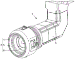
Fig. 2 is a schematic perspective view of an example of an adsorption arm used in the blade replacement mechanism of the embodiment.
Fig. 3 is a schematic perspective view of the suction arm shown in fig. 2 viewed from another angle.
Fig. 4 is a schematic plan view of the adsorption unit shown in fig. 2 and 3.
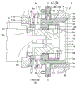
Fig. 5 is a schematic cross-sectional view of the adsorption unit shown in fig. 2 to 4.
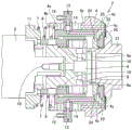
Fig. 6 is a first schematic cross-sectional view illustrating a part of the process of the blade replacement method according to the embodiment.
Fig. 7 is a second schematic sectional view illustrating a part of the process of the blade replacement method according to the embodiment.
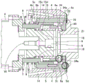
Fig. 8 is a third schematic sectional view illustrating a part of the process of the blade replacement method according to the embodiment.
Fig. 9 is a fourth schematic cross-sectional view illustrating a part of the process of the blade replacement method according to the embodiment.
Fig. 10 is a schematic cross-sectional view five illustrating a part of the process of the blade replacement method according to the embodiment.
Fig. 11 is a schematic perspective view of a cutting device according to an exemplary embodiment in which the suction unit is located at the first operation position.
Fig. 12 is a schematic perspective view of the cutting device shown in fig. 11 viewed from another angle.
Fig. 13 is a schematic perspective view of the cutting device according to the embodiment in which the suction unit is in the second operation position.
Fig. 14 is a schematic perspective view of a cutting device according to another embodiment in a state where the suction unit is located at the first operation position.
Fig. 15 is a schematic perspective view of the cutting device shown in fig. 14 viewed from another angle.
Fig. 16 is a schematic perspective view illustrating an example of moving the suction unit in the Y direction by the first slide mechanism of the embodiment.
Fig. 17 is a schematic perspective view illustrating another example of moving the suction unit in the Y direction by the first slide mechanism of the embodiment.
Fig. 18 is a schematic perspective view illustrating an example of moving the suction unit in the Z direction by the second slide mechanism of the embodiment.
Fig. 19 is a schematic perspective view illustrating another example of moving the suction unit in the Z direction by the second slide mechanism of the embodiment.
Fig. 20 is a schematic perspective view illustrating an example of rotating the adsorption unit in the X- θ direction by the first rotating mechanism of the embodiment.
Fig. 21 is a schematic perspective view illustrating another example of rotating the adsorption unit in the X- θ direction by the first rotating mechanism of the embodiment.
Fig. 22 is a schematic perspective view illustrating an example of rotating the adsorption unit in the Y- θ direction by the second rotation mechanism of the embodiment.
Fig. 23 is a schematic perspective view illustrating another example of rotating the adsorption unit in the Y- θ direction using the second rotating mechanism of the embodiment.
Fig. 24 is a schematic perspective view of the housing portion of the embodiment.
Fig. 25 is a schematic perspective view of the housing shown in fig. 24 when the blade pressing member of the embodiment is erected.
Fig. 26 is a schematic plan view of a detection unit of the embodiment.
Fig. 27 is a flowchart of an example of a method for detecting at least one of wear and damage of the blade by the detection unit according to the embodiment.
[ description of symbols ]
1: adsorption arm
2: adsorption unit
3: arm part
4: first adsorption part
4 a: projection part
4 b: proximal surface of the protrusion
4 c: distal surface of the first adsorption part
4 x: the first adsorption port
4 y: a first adsorption tank
4z, 5z, 13, 14: gas flow path
5: second adsorption part
5 a: hook-shaped part
5 b: distal surface of hook portion
5 c: proximal surface of hook portion
5 d: distal surface of the second adsorption part
5 x: second adsorption port
5 y: second adsorption tank
6: rotating part for assembling and disassembling component
6 a: projection part
6 b: proximal surface of rotating part
7: third spring
8: second spring
9: rotary driving member
9 a: far side of the near side extension part
10: shaft
11: connecting part
11 a: projection part
11 b: inner proximal surface of the joint
11 c: outer proximal surface of the joint
12: gas suction port
15: sleeve pipe
15 a: containing part
15 b: support part
15 c: near surface of the containing part
15 d: distal surface of the support portion
16: first spring
20: proximal flange
21: main shaft
22: blade
23: distal flange
24: loading and unloading component
24 a: through hole
25: second main shaft
31. 32, 61, 62, 71, 72, 81, 91, 92, 102: arrow head
40: moving mechanism
41: first sliding mechanism
42: second sliding mechanism
43: first rotating mechanism
44: second rotating mechanism
51: storage part
53 a: first blade box
53 b: second blade box
53 c: third blade box
54 a: first blade pressing member
54 b: second blade pressing member
54 c: third blade pressing member
82: first imaginary plane
93: second imaginary plane
100: detection part
101: laser sensor
103: electric machine
110: platform for inspection
111: cutting device
112: sealed substrate
113: substrate supply mechanism
114: cutting platform
115: moving mechanism
116: rotating mechanism
120: blade replacing mechanism
121: cut substrate
122: tray
A: substrate supply module
B: substrate cutting module
C: inspection module
CTL: control unit
P: article of manufacture
S1-S4: step (ii) of
Detailed Description
Hereinafter, embodiments will be described. In the drawings for describing the embodiments, the same reference numerals denote the same or corresponding parts.
Fig. 1 is a schematic plan view of a cutting apparatus according to an embodiment of the cutting apparatus of the present invention. As shown in fig. 1, the cutting device of the embodiment is a device for cutting an object to be cut into a plurality of pieces. The cutting device 111 according to the embodiment includes a substrate supply module a, a substrate cutting module B, and an inspection module C as components. Each component (each of the modules a to C) is detachable and replaceable with respect to the other components.
The substrate supply module a includes, for example: a substrate supply mechanism 113 configured to supply a sealed substrate 112 corresponding to an example of a cutting object; and a control unit CTL configured to perform operations, control, and the like of the cutting device 111. The sealed substrate 112 includes, for example: a printed circuit board (not shown) or a substrate including lead frames (not shown), a plurality of functional elements (chips such as semiconductor elements) (not shown) mounted in a plurality of regions of the substrate, and a sealing resin (not shown) formed so as to cover the plurality of regions in a unified manner. The sealed substrate 112 is a cut object that is finally cut and singulated. The sealed substrate 112 can be transported to the substrate cutting module B by, for example, a transport mechanism (not shown).
The substrate cutting module B can include, for example: a cutting stage 114 configured to provide the sealed substrate 112, a moving mechanism 115 configured to move the cutting stage 114 in the Y direction, a rotating mechanism 116 configured to rotate the cutting stage 114 in the θ direction, a spindle 21 described later, and a blade replacing mechanism 120 of an embodiment described later. For example, the cutting stage 114 may include a cutting jig (not shown), and when the cutting stage 114 includes a cutting jig, the sealed substrate 112 may be placed on the cutting jig.
In fig. 1, the cutting device 111 of the embodiment is illustrated as a single-spindle cutting device having one spindle 21 for convenience of explanation. However, the cutting device 111 according to the embodiment is not limited to the cutting device having the single spindle, and may be a cutting device having a double spindle configuration having two spindles, for example, as described below.
The main shaft 21 can be configured to be movable independently in the X direction and the Z direction, for example. A disc-shaped blade 22, for example, can be attached to the distal end of the rotation shaft of the spindle 21. The blade 22 can be fixed in parallel with a plane (a plane including the Y axis and the Z axis) orthogonal to the axial direction (X direction) of the rotation axis, for example. The spindle 21 may include a cutting water nozzle (not shown) for jetting cutting water, for example, to suppress frictional heat generated by the blade 22 rotating at a high speed. Further, the sealed substrate 112 can be cut while the cutting table 114 is moved relative to the spindle 21. The blade 22 may be configured to cut the sealed substrate 112 by rotating in a plane including the Y axis and the Z axis, for example.
The inspection module C may include, for example, an inspection stage 110 and a tray 122. The inspection stage 110 can be configured to be capable of providing a cut substrate 121, for example, the cut substrate 121 being an aggregate including a plurality of products P obtained by cutting and singulating the sealed substrate 112. The plurality of products P can be inspected by, for example, an inspection camera (not shown) and sorted into good products and defective products. The tray 122 may be configured to accommodate the products P sorted as good products, for example.
Fig. 2 is a schematic perspective view showing an example of an adsorption arm used in the blade replacement mechanism according to the embodiment. The adsorption arm 1 includes an adsorption unit 2 and an arm 3 attached to the adsorption unit 2. The suction unit 2 is attached to one end of the arm 3.
Fig. 3 is a schematic perspective view of the suction arm 1 shown in fig. 2 when viewed from another angle. The suction unit 2 includes a cylindrical first suction portion 4, a cylindrical second suction portion 5, and an annular attachment/detachment member rotating portion 6. In fig. 2, the attachment/detachment member rotating portion 6, the second suction portion 5, and the first suction portion 4 are illustrated as follows: the surface of the suction unit 2 on the far side is seen in the order of the first suction unit 4, the second suction unit 5, and the detachable member rotating unit 6 from the suction side (far side) to the arm 3 side (near side) of the suction unit 2. In the description of the suction unit 2, the near side refers to the arm 3 side, and the far side refers to the suction side of the suction unit 2.
Fig. 4 shows a schematic plan view of the adsorption unit 2 shown in fig. 2 and 3. The second suction portion 5 is located inside the first suction portion 4, and the attachment/detachment member rotating portion 6 is located inside the second suction portion 5. The first suction portion 4 includes a plurality of first suction ports 4x configured to suck a blade described later, and an annular first suction groove 4y communicating with the plurality of first suction ports 4 x. The second suction portion 5 includes a plurality of second suction ports 5x configured to suck a flange or a hub, which will be described later, and an annular second suction groove 5y communicating with the plurality of second suction ports 5 x. The attachment/detachment member rotation portion 6 includes a plurality of protrusions 6a arranged in a ring shape with a space therebetween. The attachment/detachment member rotation portion 6 is configured to be rotatable and rotatable in the direction of the arrow in fig. 4, for example, but the rotation direction of the attachment/detachment member rotation portion 6 is not particularly limited.
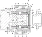
Fig. 5 shows a schematic cross-sectional view of the adsorption unit 2 shown in fig. 2 to 4. The first suction part 4 is hollow, and the hollow second suction part 5 is located inside the hollow of the first suction part 4. A gas flow path 14 is provided in an outer wall surrounding the hollow portion of the first adsorption part 4, and the gas flow path 14 is configured to communicate with the first adsorption groove 4y through the first adsorption port 4x and suck a blade described later. The gas flow path 14 is connected to a gas flow path 4z communicating with the first adsorption port 4 x. The first suction part 4 includes a protruding part 4a protruding inward from a part of the outer wall of the first suction part 4 on the near side. The protruding portion 4a includes a protruding portion near surface 4b on the near side of the protruding portion 4 a. The first suction part 4 includes a first suction part distal surface 4c as a distal surface of the first suction part 4.
A gas flow path 13 is provided in an outer wall surrounding the hollow portion of the second adsorption portion 5, and the gas flow path 13 is configured to communicate with the second adsorption groove 5y through the second adsorption port 5x and adsorb the flange or the hub. A gas suction port 12 configured to suck the gas in the gas flow path 13 is attached to one end of the gas flow path 13. The other end of the gas channel 13 is connected to a gas channel 5z communicating with the second adsorption port 5 x. The second suction portion 5 includes a hook portion 5a protruding inward at an end portion on the near side of the second suction portion 5. The hook portion 5a includes a hook portion distal surface 5b as a distal surface, and a hook portion proximal surface 5c as a proximal surface. The second suction unit 5 includes a second suction unit distal surface 5d as a distal surface of the second suction unit 5.
The second suction portion 5 is also hollow, and the attachment/detachment member rotating portion 6 is located inside the hollow of the second suction portion 5. The protruding portion 6a of the attachment/detachment member rotating portion 6 is a member in which the attachment/detachment member rotating portion 6 partially protrudes toward the far side. A rotatable rotation driving member 9 is attached to the near side of the detachable member rotating portion 6. The rotation driving means 9 rotates about the shaft 10, and the attachment/detachment member rotating portion 6 can also rotate. A part of the detachable member rotating portion 6 on the far side extends outward beyond the rotation driving member 9. The portion of the detachable member rotating portion 6 that protrudes outward includes a rotating portion near surface 6b as a near surface. The near side of the rotary drive member 9 also partially protrudes outward. The portion of the rotation driving member 9 protruding outward has a near-side protruding portion distal surface 9a as a distal surface.
A cylindrical sleeve (sleeve)15 is located at a position surrounding the removable member rotating portion 6, the rotary drive member 9, and the shaft 10. The sleeve 15 includes an accommodating portion 15a configured to accommodate the attachment/detachment member rotating portion 6, and a support portion 15b configured to support the accommodating portion 15 a. The receiving portion 15a extends outward beyond the support portion 15 b. The storage portion 15a includes a storage portion near surface 15c as a near side surface. The receiving portion near surface 15c faces the hook portion far surface 5 b. The support portion 15b includes a support portion distal surface 15d as a distal surface.
A coupling portion 11 configured to couple the suction unit 2 and the arm 3 is attached to the near side of the sleeve 15. The coupling portion 11 is attached to the sleeve 15 by fitting the distal protrusion 11a of the coupling portion 11 into the proximal hollow of the sleeve 15. The coupling portion 11 includes a coupling portion inner proximal surface 11b facing the hook-shaped portion proximal surface 5c, and a coupling portion outer proximal surface 11c facing the protruding portion proximal surface 4 b. The coupling portion outer near surface 11c is located further outward than the coupling portion inner near surface 11 b.
The first spring 16 is located at a position surrounding the periphery of the rotation driving member 9 between the rotation part near surface 6b and the near-side projecting part far surface 9 a. The first spring 16 can expand and contract by changing the distance between the proximal surface 6b of the rotating portion and the distal surface 9a of the proximal protruding portion.
The second spring 8 is located at a position surrounding the periphery of the support portion 15b between the hook-shaped portion proximal surface 5c and the coupling portion inner proximal surface 11 b. The second spring 8 can expand and contract by changing the distance between the hook-shaped portion proximal surface 5c and the coupling portion inner proximal surface 11 b.
The third spring 7 is located at a position surrounding the second spring 8 between the near protrusion surface 4b and the near coupling portion outer surface 11 c. The third spring 7 can expand and contract by changing the distance between the projection near-side surface 4b and the coupling portion outer near-side surface 11 c.
Hereinafter, a blade replacement method according to an embodiment using the blade replacement mechanism according to the embodiment including the suction arm will be described. In the present embodiment, a case where the blade 22 is a hubless blade having no hub is described, but the present embodiment is not limited to the hubless blade, and can be applied to a hub blade having a hub in the blade 22.
First, as shown in the schematic sectional view of fig. 6, the suction unit 2 is brought close to the used blade 22. Here, the used blade 22 to be replaced is sandwiched between the near-side flange 20 and the far-side flange 23 of the spindle 21. The distal flange 23 is fastened to the proximal flange 20 by a fastening member 24 such as a nut, and the blade 22 is fixed between the proximal flange 20 and the distal flange 23 of the spindle 21. The near side of the near side flange 20 is the near side with respect to the main shaft 21, and the far side of the far side flange 23 is the far side with respect to the main shaft 21.
Next, as shown in the schematic cross-sectional view of fig. 7, the suction unit 2 is further moved to the far side (the spindle 21 side) until the first suction portion far surface 4c of the first suction portion 4 comes into contact with the near side (the arm 3 side) surface of the blade 22.
Then, as shown in the schematic cross-sectional view of fig. 8, the arm 3 is moved to the far side (the spindle 21 side) to further move the suction unit 2 to the far side (the spindle 21 side). At this time, although the first suction part 4 is urged from the far side (the spindle 21 side) to the near side (the arm 3 side) by the blade 22, the third spring 7 contracts by contacting the projecting part near surface 4b, so that the movement of the first suction part 4 is suppressed, and the excessive load on the blade 22 is suppressed. Then, in a state where the movement of the first suction part 4 is suppressed, the second suction part 5 moves to the far side (the spindle 21 side), and the far side second suction part far surface 5d of the second suction part 5 comes into contact with the far side flange 23.
When the projection 6a of the attachment/detachment member rotating portion 6 is not fitted into the through hole 24a of the attachment/detachment member 24 after the second suction portion distal surface 5d of the second suction portion 5 comes into contact with the distal flange 23, the first spring 16 contracts, and the attachment/detachment member rotating portion 6 moves in the direction of the arrow 31 toward the near side (toward the arm portion 3). At this time, although the second suction part 5 is urged from the far side (the spindle 21 side) to the near side (the arm part 3 side) by the far side flange 23, the second spring 8 is contracted by contacting the hook-shaped part near surface 5c, and therefore, the movement of the second suction part 5 is suppressed.
Then, as shown in the schematic cross-sectional view of fig. 9, when the protruding portion 6a of the attachment/detachment member rotating portion 6 is not fitted into the through-hole 24a of the attachment/detachment member 24, the attachment/detachment member rotating portion 6 is rotated, for example, in the direction of the arrow 32. When the projection 6a of the attachment/detachment member rotating portion 6 reaches the position of the through hole 24a of the attachment/detachment member 24 by the rotation of the attachment/detachment member rotating portion 6, the first spring 16 extends, and the projection 6a is fitted into the through hole 24 a.
Subsequently, the detachable member rotating unit 6 rotates to rotate the detachable member 24. This releases the fastening of the far-side flange 23 to the near-side flange 20 by the detachable member 24. Then, the first suction part 4 sucks the blade 22, and the second suction part 5 sucks the distal flange 23. Thereafter, the suction unit 2 is moved to the near side (arm 3 side), and the blade 22 and the far side flange 23 are removed from the spindle 21 together with the removable member 24, as shown in a schematic cross-sectional view of fig. 10, for example.
Then, the suction unit 2 is moved from the first operating position where the blade 22 can be attached and detached shown in the schematic perspective views of fig. 11 and 12 to the second operating position where the replacement blade can be taken out of and stored in the storage section 51 shown in the schematic perspective view of fig. 13. Fig. 11 and 12 are schematic perspective views of the cutting device according to the embodiment in an example of a state in which the suction unit 2 is located at the first operating position, and fig. 13 is a schematic perspective view of the cutting device according to the embodiment in an example of a state in which the suction unit 2 is located at the second operating position.
The cutting device of the embodiment shown in fig. 11 to 13 includes a second main shaft 25 at a position facing the main shaft 21. For example, as shown in the schematic perspective views of fig. 14 and 15, the suction unit 2 of the blade replacement mechanism according to the embodiment can attach and detach not only the blade 22 of the spindle 21 but also the blade 22 of the second spindle 25. Fig. 14 and 15 are schematic perspective views of a cutting device according to another example of the embodiment when the suction unit 2 is located at the first operating position.
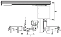
As shown in the schematic perspective views of fig. 11 to 15, the blade replacement mechanism according to the embodiment includes a moving mechanism 40, and the moving mechanism 40 includes a first slide mechanism 41 and a second slide mechanism 42. For example, as shown in schematic perspective views of fig. 16 and 17, the first slide mechanism 41 can move the suction unit 2 by sliding in the Y direction shown by arrows 61 and 62. The movement of the suction unit 2 in the Y direction can be used, for example, to move the suction unit 2 to the first operation position and to the second operation position.
For example, as shown in the schematic perspective views of fig. 18 and 19, the second slide mechanism 42 can move the suction unit 2 by sliding in the Z direction shown by arrows 71 and 72. The movement of the suction unit 2 in the Z direction can be used, for example, for one step for moving from the first operating position to the second operating position, one step for moving from the second operating position to the first operating position, and the like. The Z direction indicated by arrows 71 and 72 in fig. 18 and 19 intersects the Y direction indicated by arrows 61 and 62 in fig. 16 and 17.
The blade replacement mechanism according to the embodiment includes a first rotation mechanism 43 shown in schematic perspective views of fig. 20 and 21, and a second rotation mechanism 44 shown in schematic perspective views of fig. 22 and 23.
For example, as shown in fig. 20 and 21, the first rotation mechanism 43 is configured to rotate the suction unit 2 in the X- θ direction indicated by the arrow 81 in the first virtual plane 82. The rotation of the adsorption unit 2 in the X- θ direction can be used, for example, for one step for moving from the first operation position to the second operation position, one step for moving from the second operation position to the first operation position, and the like.
For example, as shown in fig. 22 and 23, the second rotation mechanism 44 is configured to be able to rotate the suction unit 2 in the Y- θ direction indicated by arrows 91 and 92 in the second virtual plane 93. The rotation of the suction unit 2 in the Y- θ direction can be used, for example, to move the suction unit 2 from the main shaft 21 to the second main shaft 25 and to move the suction unit 2 from the second main shaft 25 to the main shaft 21. The second imaginary plane 93 is an imaginary plane different from the first imaginary plane 82, and the first imaginary plane 82 and the second imaginary plane 93 intersect with each other.
Fig. 24 is a schematic perspective view of the housing section 51 of the blade replacement mechanism according to the embodiment. The housing 51 includes a first blade case 53a, a second blade case 53b, and a third blade case 53c in this order from the uppermost stage to the lowermost stage. The housing 51 includes a first blade pressing member 54a, a second blade pressing member 54b, and a third blade pressing member 54 c. The first blade pressing member 54a, the second blade pressing member 54b, and the third blade pressing member 54c are configured to press the blades stored in the first blade case 53a, the second blade case 53b, and the third blade case 53c around the respective blade cases. Thereby, the blade can be suppressed from falling from the blade cartridge.
The suction unit 2 of the blade replacement mechanism according to the embodiment removes the used blade from the spindle 21 or the second spindle 25 as described above, and then moves to the second operation position shown in fig. 13 together with the used blade sucked by the suction unit 2. At this time, for example, as shown in the schematic perspective view of fig. 25, at least one of the first blade pressing member 54a, the second blade pressing member 54b, and the third blade pressing member 54c rises upward to release the pressing of the blade.
Next, the suction unit 2 that has sucked the used blade is brought close to an empty blade cassette that does not contain a blade, and the central opening of the used blade is fitted into the empty blade cassette. Then, the suction unit 2 stops only the suction of the used blade by the first suction portion 4, and leaves from the blade cartridge. This enables the used blade to be stored in the empty blade cartridge.
Then, the suction unit 2 moves to another blade cassette that stores the replacement blade. Next, the blade pressing member that presses the replacement blade is raised upward to release the pressing of the replacement blade. Thereafter, the suction unit 2 is brought close to the replacement blade, and the first suction portion distal surface 4c of the first suction portion 4 of the suction unit 2 is brought into contact with the surface of the replacement blade. Next, the replacement blade is sucked from the gas suction port 12 through the gas flow path 13 of the first suction unit 4, and is thereby sucked to the first suction unit distal surface 4 c.
The suction unit 2, which has sucked the replacement blade, is moved from the second operating position shown in fig. 13 to the first operating position shown in fig. 11 and 12. Then, as shown in fig. 10, the suction unit 2 is moved to the far side to bring the suction unit 2 close to the spindle 21.
Next, as shown in fig. 9, the suction unit 2 is further moved to the remote side (the spindle 21 side). Thereby, the distal flange 23 comes into contact with the proximal flange 20 of the main shaft 21, and the replacement blade 22 is sandwiched between the proximal flange 20 and the distal flange 23. Then, the removable member rotating portion 6 is rotated in the direction opposite to the arrow 32 to rotate the removable member 24, whereby the distal flange 23 is fastened to the proximal flange 20 by the removable member 24. This allows the replacement blade 22 to be fixed between the near-side flange 20 and the far-side flange 23. Thereafter, the suction of the replacement blade 22 by the first suction part 4 is stopped, and the suction of the distal flange 23 by the second suction part 5 is stopped.
Next, as shown in fig. 6, the suction unit 2 is moved to the near side (the arm 3 side) to separate the suction unit 2 from the spindle 21. This completes the attachment of the replacement blade 22 to the spindle 21.
As described above, the embodiment can realize automatic replacement of the blade 22.
Fig. 26 is a schematic plan view of the detection section 100 used in the blade replacement mechanism of the embodiment. In the embodiment, the detection unit 100 includes a laser sensor 101 and a motor 103. The detection unit 100 is configured to move the laser sensor 101 in the direction of the arrow 102 by driving the motor 103.
Fig. 27 is a flowchart showing an example of a method for detecting at least one of wear and damage of the blade 22 by the detection unit 100. First, in step 1(S1), the position adjustment laser light shielding rate a is measured. S1 can be performed as follows, for example.
First, the position of the laser sensor 101 is adjusted. Here, the laser sensor 101 is adjusted, for example, so that the edge of the blade 22 before cutting is started is positioned between a laser light emitting unit (not shown) and a laser light detecting unit (not shown). Then, the laser beam is emitted from the emission portion of the laser sensor 101 with the position of the laser sensor 101 adjusted, and is detected by the detection portion. Then, the light-shielding rate of the laser light in this state (position adjustment laser light-shielding rate a) was measured. The position adjustment laser light shielding rate a is a ratio of a detection amount of the laser light detected by the laser light detection unit to an emission amount of the laser light in a state after the position adjustment of the laser sensor 101 and before the start of cutting. Since the incidence of the laser light to the detection portion tends to be blocked by the edge of the blade 22 before the cutting start, the position adjustment laser light blocking ratio a can be increased.
Then, in step 2(S2), the wear or damage detection laser light shielding rate a' is measured. S2 can be performed as follows, for example.
First, the spindle 21 is rotated to rotate the blade 22. Then, the object to be cut is cut by the rotating blade 22. Next, in a state where the object to be cut is being cut by the rotating blade 22, laser light is emitted from the emitting portion of the laser sensor 101 and detected by the detecting portion. Then, the light shielding rate of the laser light in this state (wear or damage detection laser light shielding rate a') was measured. When the blade 22 is worn or damaged by cutting, the incidence of the laser beam on the detection unit is less likely to be blocked by the edge of the blade 22 than before the cutting is started, and therefore the wear or damage detection laser beam blocking rate a' can be lower than the position adjustment laser beam blocking rate a.
Then, in step 3(S3), the light blocking ratio a of the laser light measured in S1 is compared with the light blocking ratio a' of the laser light measured in S2. At this time, when the light shielding rate a of the laser beam is equal to the light shielding rate a 'of the laser beam, the cutting object is cut without stopping the rotation of the blade 22, and the process returns to S2 again to measure the wear or damage detection laser beam light shielding rate a'.
On the other hand, if it is determined in S3 that the light shielding rate a of the laser beam is not equal to the light shielding rate a' of the laser beam, the rotation of the blade 22 is stopped and the blade 22 is automatically replaced in step 4 (S4).
As described above, in the case where the blade replacement mechanism of the embodiment includes the detection unit 100 configured to be able to detect at least one of wear and damage of the blade 22, the automatic replacement of the blade 22 of the embodiment can be performed by automatically stopping the cutting by the rotation of the blade 22 after at least one of wear and damage of the blade 22 is detected. Thereby enabling further automation of the replacement of the blade 22.
As described above, the embodiments are explained, but it is also expected that the configurations of the above embodiments are appropriately combined from the beginning.
The embodiments of the present invention have been described, but the embodiments disclosed herein are to be considered in all respects as illustrative and not restrictive. The scope of the present invention is defined by the claims, and all changes that come within the meaning and range of equivalency of the claims are intended to be embraced therein.
Claims (11)
1. A blade changing mechanism, comprising:
a first suction part configured to suck the blade;
a second suction part which is positioned inside the first suction part and configured to suck the flange independently of the suction of the first suction part; and
a detachable member rotating part which is positioned inside the second adsorption part and is configured to rotate a detachable member which can detach the blade from the main shaft and which is used for detaching the blade from the main shaft
The blade is replaced in the following state: the flange is sucked by the second suction portion, and the removable member removed from the main shaft by being rotated by the removable member rotating portion is accommodated inside the flange.
2. The blade changing mechanism of claim 1 wherein said attachment and detachment member is a nut.
3. The blade changing mechanism of claim 1 further comprising an arm,
the arm is attached to an adsorption unit including the first adsorption part, the second adsorption part, and the detachable member rotating part.
4. The blade changing mechanism according to claim 3, further comprising a housing portion capable of housing a changing blade.
5. The blade changing mechanism of claim 4 further comprising a moving mechanism,
the moving mechanism is configured to move the suction unit between a first operating position where the blade is attachable and detachable and a second operating position where the replacement blade is removable from the housing.
6. The blade changing mechanism according to claim 5, wherein the moving mechanism includes: a first slide mechanism configured to move the suction unit in a first direction; a second sliding mechanism configured to move the suction unit in a second direction intersecting the first direction; and a rotation mechanism configured to rotate the adsorption unit.
7. The blade changing mechanism according to claim 6, wherein the rotating mechanism includes: a first rotation mechanism configured to rotate the suction unit in a first virtual plane; and a second rotation mechanism configured to rotate the suction unit in a second virtual plane different from the first virtual plane.
8. The blade replacement mechanism according to any one of claims 1 to 7, further comprising a detection portion configured to detect at least one of wear and breakage of the blade.
9. A cutting device characterized by comprising the blade changing mechanism according to any one of claims 1 to 8, the blade, and the spindle.
10. A blade replacement method using a blade replacement mechanism, the blade replacement mechanism comprising: a first suction part configured to suck the blade; a second suction part which is positioned inside the first suction part and configured to suck the flange independently of the suction of the first suction part; and a detachable member rotating section which is located inside the second suction section and is configured to be capable of rotating a detachable member which is capable of detaching the blade from the spindle; and the blade replacement method is characterized by comprising the following steps:
rotating the attachment/detachment member by the attachment/detachment member rotating portion in a state where the blade is adsorbed by the first adsorbing portion and the flange is adsorbed by the second adsorbing portion independently of the adsorption of the first adsorbing portion, detaching the attachment/detachment member from the spindle, and accommodating the attachment/detachment member inside the flange while adsorbing the flange by the second adsorbing portion;
moving an adsorption unit including the first adsorption part, the second adsorption part, and the attachment/detachment member rotation part to a housing part;
releasing the suction of the first suction portion and housing the blade in the housing portion;
sucking the replacement blade stored in the storage section by the first suction section;
moving the suction unit to fit the replacement blade into the spindle; and
the replacement blade is fixed to the main shaft by rotating the attachment/detachment member by the attachment/detachment member rotating portion.
11. The method of claim 10, further comprising the step of detecting at least one of wear and tear of the blade.
Applications Claiming Priority (2)
| Application Number | Priority Date | Filing Date | Title |
|---|---|---|---|
| JP2017-124214 | 2017-06-26 | ||
| JP2017124214A JP6560714B2 (en) | 2017-06-26 | 2017-06-26 | Blade replacement mechanism, cutting device, and blade replacement method |
Publications (2)
| Publication Number | Publication Date |
|---|---|
| CN109109071A CN109109071A (en) | 2019-01-01 |
| CN109109071B true CN109109071B (en) | 2020-12-22 |
Family
ID=64823068
Family Applications (1)
| Application Number | Title | Priority Date | Filing Date |
|---|---|---|---|
| CN201810660079.9A Active CN109109071B (en) | 2017-06-26 | 2018-06-25 | Blade replacement mechanism, cutting device, and blade replacement method |
Country Status (5)
| Country | Link |
|---|---|
| JP (1) | JP6560714B2 (en) |
| KR (1) | KR102125232B1 (en) |
| CN (1) | CN109109071B (en) |
| SG (1) | SG10201805421VA (en) |
| TW (1) | TWI666090B (en) |
Families Citing this family (9)
| Publication number | Priority date | Publication date | Assignee | Title |
|---|---|---|---|---|
| JP7229093B2 (en) * | 2019-05-13 | 2023-02-27 | 株式会社ディスコ | Blade attachment/detachment auxiliary device |
| JP7098581B2 (en) * | 2019-07-29 | 2022-07-11 | Towa株式会社 | Blade replacement mechanism, cutting device, and manufacturing method of cut products |
| JP7248557B2 (en) * | 2019-10-24 | 2023-03-29 | Towa株式会社 | Blade changing device, cutting device, and method for manufacturing cut product |
| JP7240304B2 (en) * | 2019-11-25 | 2023-03-15 | Towa株式会社 | Blade changer and cutting system |
| CN111070296B (en) * | 2020-02-26 | 2020-08-25 | 永康雪纺自动化设备有限公司 | Automatic blade replacing device for cutting wheel |
| KR102246541B1 (en) * | 2020-09-28 | 2021-04-30 | (주)네온테크 | Hybrid blade change module and blade auto supplying method using the same |
| CN112318602B (en) * | 2020-10-20 | 2022-06-07 | 耿莉 | Automatic tool changing device for pathological slicing knife |
| JP2022148902A (en) | 2021-03-24 | 2022-10-06 | Towa株式会社 | Processing device, and production method of processed product |
| CN114147871A (en) * | 2021-11-30 | 2022-03-08 | 湖北省华建石材股份有限公司 | Reloading device for tower type circular saw and working method |
Citations (7)
| Publication number | Priority date | Publication date | Assignee | Title |
|---|---|---|---|---|
| JPH06326186A (en) * | 1994-02-04 | 1994-11-25 | Disco Abrasive Syst Ltd | Auto-changer for blade |
| JPH11340169A (en) * | 1998-05-22 | 1999-12-10 | Tokyo Seimitsu Co Ltd | Automatic blade exchange system |
| CN102554666A (en) * | 2010-12-22 | 2012-07-11 | 东和株式会社 | Blade attached and removed device |
| CN103567793A (en) * | 2012-07-18 | 2014-02-12 | 东和株式会社 | Blade detachable device |
| CN105397544A (en) * | 2014-09-08 | 2016-03-16 | 德马吉森精机株式会社 | Automatic Tool Changer And Machine Tool |
| JP2016064450A (en) * | 2014-09-22 | 2016-04-28 | 株式会社ディスコ | Cutting blade replacement system |
| CN106142198A (en) * | 2015-05-13 | 2016-11-23 | 东和株式会社 | Shearing device and cutting-off method |
Family Cites Families (10)
| Publication number | Priority date | Publication date | Assignee | Title |
|---|---|---|---|---|
| DE3533090A1 (en) * | 1985-09-17 | 1987-03-26 | Salje Ernst | DEVICE FOR CHANGING TOOLS IN GRINDING OPERATIONS |
| IT1237111B (en) * | 1989-10-23 | 1993-05-18 | Bavelloni Spa Z | AUTOMATIC MACHINE FOR ENGRAVING THE FACES OF SLABS IN GENERAL AND GLASS SLABS IN PARTICULAR. |
| JP2886326B2 (en) * | 1990-10-29 | 1999-04-26 | 株式会社東芝 | Whetstone automatic changer |
| US5220749A (en) * | 1991-11-07 | 1993-06-22 | The University Of Rochester | Grinding apparatus |
| JP5014892B2 (en) * | 2007-06-25 | 2012-08-29 | 株式会社ディスコ | Blade replacement tool |
| US7495759B1 (en) * | 2007-10-23 | 2009-02-24 | Asm Assembly Automation Ltd. | Damage and wear detection for rotary cutting blades |
| JP5346702B2 (en) * | 2009-06-15 | 2013-11-20 | 株式会社ディスコ | Mounting tool set and annular blade mounting method |
| JP6410626B2 (en) * | 2015-02-06 | 2018-10-24 | 株式会社ディスコ | Cutting equipment |
| JP6403595B2 (en) * | 2015-02-06 | 2018-10-10 | 株式会社ディスコ | Position adjustment jig and position adjustment method |
| JP6421658B2 (en) * | 2015-03-13 | 2018-11-14 | 株式会社東京精密 | Blade automatic changer and blade automatic change method |
-
2017
- 2017-06-26 JP JP2017124214A patent/JP6560714B2/en active Active
-
2018
- 2018-06-22 KR KR1020180072070A patent/KR102125232B1/en active IP Right Grant
- 2018-06-25 CN CN201810660079.9A patent/CN109109071B/en active Active
- 2018-06-25 TW TW107121621A patent/TWI666090B/en active
- 2018-06-25 SG SG10201805421VA patent/SG10201805421VA/en unknown
Patent Citations (7)
| Publication number | Priority date | Publication date | Assignee | Title |
|---|---|---|---|---|
| JPH06326186A (en) * | 1994-02-04 | 1994-11-25 | Disco Abrasive Syst Ltd | Auto-changer for blade |
| JPH11340169A (en) * | 1998-05-22 | 1999-12-10 | Tokyo Seimitsu Co Ltd | Automatic blade exchange system |
| CN102554666A (en) * | 2010-12-22 | 2012-07-11 | 东和株式会社 | Blade attached and removed device |
| CN103567793A (en) * | 2012-07-18 | 2014-02-12 | 东和株式会社 | Blade detachable device |
| CN105397544A (en) * | 2014-09-08 | 2016-03-16 | 德马吉森精机株式会社 | Automatic Tool Changer And Machine Tool |
| JP2016064450A (en) * | 2014-09-22 | 2016-04-28 | 株式会社ディスコ | Cutting blade replacement system |
| CN106142198A (en) * | 2015-05-13 | 2016-11-23 | 东和株式会社 | Shearing device and cutting-off method |
Also Published As
| Publication number | Publication date |
|---|---|
| TWI666090B (en) | 2019-07-21 |
| TW201904718A (en) | 2019-02-01 |
| KR20190001547A (en) | 2019-01-04 |
| KR102125232B1 (en) | 2020-06-22 |
| JP2019005857A (en) | 2019-01-17 |
| CN109109071A (en) | 2019-01-01 |
| JP6560714B2 (en) | 2019-08-14 |
| SG10201805421VA (en) | 2019-01-30 |
Similar Documents
| Publication | Publication Date | Title |
|---|---|---|
| CN109109071B (en) | Blade replacement mechanism, cutting device, and blade replacement method | |
| JP6101140B2 (en) | Cutting equipment | |
| CN110098106B (en) | Flange replacing mechanism, cutting device, flange replacing method and method for manufacturing cut product | |
| JP4255162B2 (en) | Electrical component mounting method and electrical component mounting system | |
| JP7126749B2 (en) | cutting equipment | |
| TWI675999B (en) | Receiving device for component and method of unloading fail component from thereof | |
| JP4969609B2 (en) | Electric component holding device | |
| TW201907467A (en) | Blade mounting and dismounting jig, blade mounting and dismounting method, blade extracting method, and cutting apparatus | |
| KR102491628B1 (en) | Blade replacement apparatus, cutting apparatus and manufacturing method of cut product | |
| JP2018075688A (en) | Flange mechanism | |
| JP2007246214A (en) | Visual inspection device | |
| JP5673929B2 (en) | Spinner cleaning apparatus and spinner cleaning method | |
| KR102056185B1 (en) | Arm of automatic exchange robot for blade | |
| TWI747374B (en) | Blade replacement mechanism, cutting device, and method for manufacturing cut products | |
| WO2022123773A1 (en) | Suction nozzle and component mounter | |
| KR102037190B1 (en) | Cutting apparatus of semiconductor package | |
| KR102037191B1 (en) | Cutting apparatus of semiconductor package | |
| JP3747613B2 (en) | Semiconductor mounting equipment | |
| JP2002120936A (en) | Article supply device | |
| JP2002178284A (en) | Device to detect kind of part suction nozzle at working position and electronic part installation device |
Legal Events
| Date | Code | Title | Description |
|---|---|---|---|
| PB01 | Publication | ||
| PB01 | Publication | ||
| SE01 | Entry into force of request for substantive examination | ||
| SE01 | Entry into force of request for substantive examination | ||
| GR01 | Patent grant | ||
| GR01 | Patent grant |