Detailed Description
Hereinafter, an embodiment of the present disclosure will be described in detail with reference to the drawings. The structure, shape, and the like described below are examples for explanation, and can be changed as appropriate according to the specification of the screen printing apparatus. In the following, corresponding elements are denoted by the same reference numerals throughout the drawings, and redundant description thereof will be omitted. Hereinafter, the conveyance direction of the substrate (the left-right direction of the paper surface of fig. 2) is defined as the X direction, the conveyance direction of the mask orthogonal to the X direction within the horizontal plane (the left-right direction of the paper surface of fig. 1 and the up-down direction of the paper surface of fig. 2) is defined as the Y direction, and the vertical direction orthogonal to the horizontal plane (the up-down direction of the paper surface of fig. 1) is defined as the Z direction. Hereinafter, front, rear, left, and right are defined based on the traveling direction of the mask. Specifically, "front" is the direction of travel of the mask and is the negative orientation of the Y-axis. "rear" is the opposite direction of the travel direction of the mask and is the positive orientation of the Y-axis. "left" is the left side when viewed from the direction of travel of the mask, and is the negative orientation of the X-axis. "right" is the right side when viewed from the direction of travel of the mask, and is the positive direction of the X-axis.
First, the structure of the screen printing apparatus 1 will be described with reference to fig. 1 to 3. In fig. 1 and 2, a screen printing apparatus 1 is an apparatus for printing paste such as solder paste on a substrate 4 through a mask M developed on a frame 3 surrounding a screen 2 in which an opening 2h is formed. The screen printing apparatus 1 includes a substrate holding and moving unit 5, a squeegee unit 6, a camera unit 7, and a paste supply device (not shown). In the case where a distinction is required below, in a state where the mask M is disposed in the screen printing apparatus 1, the frame 3 on the front side in the Y direction is referred to as a front frame 3F, the frame 3 on the rear side in the Y direction is referred to as a rear frame 3B, the frame 3 on the right side in the X direction is referred to as a right frame 3R, and the frame 3 on the left side in the X direction is referred to as a left frame 3L.
The substrate holding and moving means 5 is provided on the base 8 and holds and moves the substrate 4. The right frame 3R and the left frame 3L are supported from below by a pair of mask guides 9 extending in the Y direction, and the mask M is held in a horizontal posture at a predetermined position in the screen printing apparatus 1. The mask M is used for printing paste on the substrate 4 held by the substrate holding/moving unit 5. The mask M is held at a printing position Pp where the paste is printed on the substrate 4 above the substrate holding and moving unit 5. The squeegee unit 6 is disposed above the mask M. The camera unit 7 is disposed below the mask M. The paste supply device is provided integrally with the squeegee unit 6, and supplies paste onto the screen 2 of the mask M held at the printing position Pp.
Next, details of each part included in the screen printing apparatus 1 will be described in order. In fig. 1, in the substrate holding and moving unit 5, an XY θ moving mechanism 11, a base table 12, a 1 st elevation table 13, and a 2 nd elevation table 14 are provided on a base 8 in this order from below. The base table 12 moves in a horizontal plane by the XY θ movement mechanism 11, and performs θ rotation around the Z axis. The 1 st elevation table 13 is elevated with respect to the base table 12 by a 1 st elevation table elevation motor 13 m. The 2 nd elevation table 14 is elevated with respect to the 1 st elevation table 13 by a 2 nd elevation table elevation motor 14 m.
A pair of conveyor support members 15 extending upward through the 2 nd elevation table 14 is provided above the 1 st elevation table 13. The pair of conveyor supporting members 15 support a pair of conveyors 16 extending in the X direction and arranged to face each other in the Y direction. The pair of conveyors 16 support both ends of the substrate 4 from below and convey the same in the X direction. A lower receiving member 17 is provided on the upper surface of the 2 nd elevating table 14.
A pair of gripping members (grippers 18) arranged along the X direction and facing each other in the Y direction are provided above the pair of conveyors 16. The pair of grippers 18 are opened and closed in the Y direction by the operation of the gripper opening and closing cylinder 18s, and hold (grip) both end portions of the substrate 4 supported by the lower receiving member 17.
In fig. 2, openings 2h are formed in the screen 2 of the mask M corresponding to the electrodes 4a of the substrate 4. Further, a set of mask-side marks 2m corresponding to a set of substrate-side marks 4m provided at diagonal positions on the substrate 4 is provided on the screen 2. When the substrate 4 is raised to contact the mask M in a state where these substrate-side marks 4M and mask-side marks 2M are aligned in a plan view, the electrode 4a of the substrate 4 is aligned with the opening 2h of the mask M.
In fig. 1 and 2, the doctor unit 6 includes two scrapers 22, and the two scrapers 22 are disposed to face each other in the Y direction below the doctor base 21 extending in the X direction. The blade base 21 is moved in the Y direction by the blade unit moving mechanism 23. The two scrapers 22 are individually lifted and lowered with respect to the scraper base 21 by a scraper lifting cylinder 24 provided to the scraper base 21.
In fig. 1 and 2, the camera unit 7 includes an upper camera 31 whose imaging field of view is directed upward and a lower camera 32 whose imaging field of view is directed downward. The camera unit 7 is moved in a horizontal plane by a camera unit moving mechanism 33. When the substrate 4 is horizontally aligned with respect to the mask M held at the printing position Pp, the camera unit 7 is inserted between the substrate 4 and the mask M, and alignment is performed based on the result of imaging the mask-side marks 2M by the upper camera 31 and imaging the substrate-side marks 4M by the lower camera 32.
In fig. 2, a standby position Pw is set behind the printing position Pp in the Y direction, and the standby position Pw allows the replacement mask M inserted from an insertion port 41 provided on the rear surface of the screen printing apparatus 1 to stand by. A carrying-out position Pe for moving the used mask M to take out the mask M to the outside of the apparatus is set in front of the printing position Pp in the Y direction. The pair of mask guides 9 extends in the Y direction including the standby position Pw, the printing position Pp, and the carrying-out position Pe. The mask M inserted from the insertion port 41 is moved forward in the Y direction on the pair of mask guides 9 in the order of the standby position Pw, the printing position Pp, and the carrying-out position Pe.
In the screen printing apparatus 1 shown in fig. 3, the standby position Pw, the printing position Pp, and the carrying-out position Pe are covered by the case 1 a. This protects the operator from touching the movable portion. An insertion detection unit 40, which will be described later, is disposed on the side wall 1b behind the housing 1a so as to project rearward. An insertion port 41 into which the replacement mask M is inserted is formed in the rear surface of the insertion detector 40. A carrying-in/out port 42 for carrying in/out the substrate 4 with respect to the pair of conveyors 16 is formed in each of the left and right side walls 1c, 1d of the housing 1 a.
Next, a printing method for printing paste on the substrate 4 in the screen printing apparatus 1 configured as described above will be described. The printing method described below is performed by the screen printing apparatus 1. First, the mask M corresponding to the substrate 4 on which the paste is to be printed is moved to the printing position Pp and held. Next, after the substrate 4 is carried in and aligned with the mask M at the printing position Pp, the substrate 4 is raised to contact the mask M. Next, the paste is supplied from the paste supply device onto the screen 2 of the mask M at the printing position Pp. Next, one of the scrapers 22 is moved down in the Y direction (front-rear direction). Thereby, the paste is filled into the openings 2h of the screen 2. Next, when the substrate 4 is lowered and peeled off from the mask M, the paste filled into the opening 2h is transferred (printed) onto the electrode 4a of the substrate 4.
Next, the mask moving mechanism 50 provided in the screen printing apparatus 1 will be described with reference to fig. 4. However, when the type of the substrate 4 on which the paste is printed is changed, so-called setup change adjustment is performed in which the mask M is replaced with the corresponding mask M. In the screen printing apparatus 1 of the present embodiment, the mask M is automatically replaced by the mask moving mechanism 50 at the time of setup change adjustment.
The mask moving mechanism 50 includes a contact member 51, and the contact member 51 contacts the frame 3 of the mask M at the lower end to move the mask M. The contact member 51 is vertically moved up and down by a cylinder 52 provided in the mask moving mechanism 50 (arrow a). The contact member 51 and the cylinder 52 are moved forward and backward in the Y direction by a forward and backward movement mechanism (not shown) provided in the mask movement mechanism 50 (arrow b). The forward/backward movement mechanism may also serve as the blade unit movement mechanism 23 for moving the blade base 21 forward and backward in the Y direction. The mask moving mechanism 50 is controlled by a replacement processing unit 63 (see fig. 12) provided in the control device 60.
During setup, the mask M inserted from the insertion port 41 and positioned at the standby position Pw is automatically moved to the printing position Pp by the mask moving mechanism 50 controlled by the replacement processing unit 63. The used mask M located at the printing position Pp is automatically moved to the carrying-out position Pe by the mask moving mechanism 50 controlled by the replacement processing unit 63. The cover 1e covering and protecting the upper front of the housing 1a of the mask M is opened upward (arrow c), and the operator takes out the mask M moved to the carry-out position Pe. The used mask M is taken out by the operator without synchronization with the setup change, and the operator can take out the used mask M at any time such as when he or she visits the screen printing apparatus 1.
Next, the operation of replacing the mask M by the mask moving mechanism 50 will be described with reference to fig. 5A to 5E. The replacement work of the mask M is automatically performed under the control of the replacement processing unit 63 during setup change. In fig. 5A, the used mask M (1) is located at the printing position Pp, and the replacement mask M (2) is located at the standby position Pw. In this state, first, the replacement processing unit 63 positions the contact member 51 of the mask moving mechanism 50 behind the front frame 3F of the replacement mask M (2), and lowers the contact member 51 to a predetermined height that abuts against the front frame 3F (arrow d 1).
In fig. 5B, the replacement processing unit 63 then moves the contact member 51 forward (arrow d 2). Thus, the front frame 3F of the replacement mask M (2) presses the rear frame 3B of the used mask M (1), and the used mask M (1) and the replacement mask M (2) move forward along the pair of mask guides 9.
In fig. 5C, the replacement processing unit 63 then raises the contact member 51 to a predetermined height that does not abut against the frame 3, and moves the contact member 51 to the rear of the rear frame 3B of the replacement mask M (2) while maintaining the height (arrow d 3). In fig. 5D, the replacement processing unit 63 then lowers the contact member 51 to a height of contact with the rear frame 3B, and moves the contact member 51 forward until the used mask M (1) is moved to the carry-out position Pe (arrow D4). In this state, the replacement mask M (2) moves forward to a position beyond the printing position Pp.
In fig. 5E, the replacement processing unit 63 then raises the contact member 51 to a height at which it does not contact the frame 3, and moves the contact member 51 to the front of the rear frame 3B of the replacement mask M (2) while maintaining the height. Next, the replacement processing unit 63 lowers the contact member 51 to a height at which the contact member abuts against the rear frame 3B, and moves the contact member 51 rearward until the replacement mask M (2) is moved to the printing position Pp (arrow d 5). Thus, the used mask M (1) is moved to the carry-out position Pe, and the replacement mask M (2) is moved to the printing position Pp.
In this way, the screen printing apparatus 1 is provided with: a mask M (1) which is spread on a frame body (3) surrounding a screen (2) in which an opening (2 h) is formed is held, a printing position (Pp) at which paste is printed on a substrate (4), and a standby position (Pw) which is located behind the printing position (Pp) and at which a mask M (2) for replacement is caused to stand by are automatically moved to the printing position (Pp).
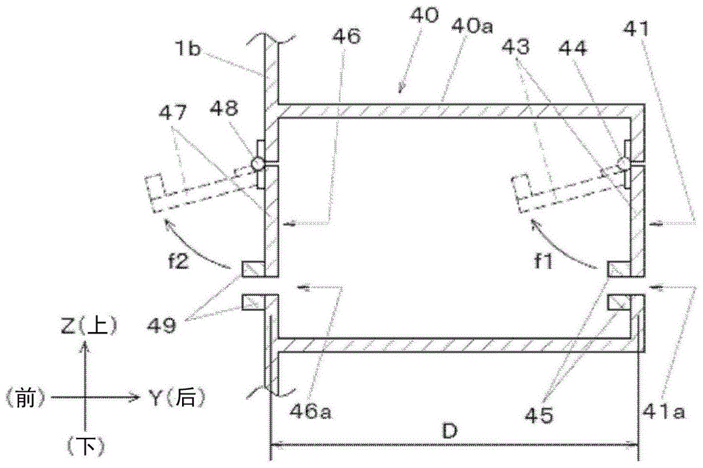
Next, the insertion detection unit 40 will be described in detail with reference to fig. 6A and 6B. Fig. 6A is an EE cross-sectional view of fig. 2 of the insertion detection unit 40. Fig. 6B is a schematic view of the insertion detector 40 viewed from the rear of the screen printing apparatus 1, i.e., from the side of the inlet 41. In fig. 6B, an insertion port 41 having a width W1 and a height H1 is formed in the rear side surface of the housing 40a of the insertion detector 40. The width W1 and the height H1 are set to be larger than the width and the height of the mask M in the horizontal posture. This allows the mask M in the horizontal posture to be inserted into the screen printing apparatus 1 from the insertion port 41 and positioned at the standby position Pw via the insertion detection unit 40.
In fig. 6A, the 1 st shutter 43 is provided at the insertion port 41. The upper portion of the 1 st shutter 43 is connected to the housing 40a of the insertion detector 40 via the 1 st hinge 44, and swings toward the inside (front) of the screen printing apparatus 1 (arrow f 1). The 1 st shutter 43 blocks the insertion port 41 in a vertically vertical state in a state where no stress is applied (a closed state shown by a solid line in fig. 6A). Further, the 1 st shutter 43 swings upward toward the inside (front) when pressed from the outside (rear) toward the inside (front) (an open state indicated by a broken line in fig. 6A). For example, when the 1 st shutter plate 43 is pressed inward by the front frame 3F (the same applies to the rear frame 3B) of the mask M inserted from the insertion port 41, the 1 st shutter plate 43 swings forward and changes from the closed state to the open state (see fig. 7B).
A 1 st sensor 45 such as a proximity sensor for detecting opening and closing of the 1 st shutter plate 43 is disposed at a lower end portion of the 1 st shutter plate 43 and a position of the housing 40a of the insertion detection unit 40 facing the lower end portion of the 1 st shutter plate 43. The detection result of the 1 st sensor 45 is transmitted to the control device 60 (see fig. 12). The 1 st sensor 45 is not limited to the example shown in fig. 6A, and may be any sensor capable of detecting whether the 1 st shutter 43 is in the open state or the closed state.
In this way, the 1 st shutter plate 43 that is pressed by the frame 3 (front frame 3F) on the front side of the inserted mask M and swings forward, and the 1 st sensor 45 that detects that the 1 st shutter plate 43 swings forward are the 1 st detection means provided in the insertion port 41 (1 st detection position) into which the mask M is inserted toward the standby position Pw, and that detects the presence or absence of the frame 3 (front frame 3F) on the front side of the mask M inserted from the insertion port 41 at the 1 st detection position. The 1 st detection means may be any means as long as it can detect the front frame 3F (rear frame 3B) of the mask M inserted from the insertion port 41 at the 1 st detection position, and may be configured by using a height sensor for detecting the height of the front frame 3F (rear frame 3B), for example.
In fig. 6B, a lower gap 41a having a height H2 is formed between the lower side of the 1 st shutter 43 and the housing 40a of the insertion detector 40. The height H2 is set to be larger than the thickness of the screen 2 of the mask M. A right gap 41b having a width W2 and a left gap 41c having a width W3 are formed between the right and left sides of the 1 st shutter 43 and the frame 40a of the insertion detector 40, respectively. The width W2 is set to be larger than the width of the right frame 3R of the mask M, and the width W3 is set to be larger than the width of the left frame 3L of the mask M. That is, the size and shape of the 1 st shutter 43 are set so that the height H2, the width W2, and the width W2 satisfy the above-described conditions.
By providing the lower gap 41a, the right gap 41b, and the left gap 41c in this way, the 1 st shutter plate 43 is in a closed state in which it does not interfere with the screen 2, the right frame 3R, and the left frame 3L of the mask M in a state where the front frame 3F of the mask M is inserted from the insertion port 41 to a position where it does not interfere with the 1 st shutter plate 43 (see fig. 8A). That is, the 1 st shutter plate 43 has a size and a shape that do not interfere with the screen 2 and the left and right frames 3 (the right frame 3R and the left frame 3L) of the inserted mask M. That is, the 1 st detection means detects an object having a predetermined height or more at the 1 st detection position. At this time, the predetermined height is smaller than the height of the frame 3 and larger than the height of the screen 2. The 1 st detection position is not limited to the position of the insertion port 41. For example, the 1 st detection position is a position on the movement path of the mask M between the insertion port 41 and the print position Pp, and may be a position closer to the insertion port 41 than the 2 nd detection position (i.e., a position farther from the print position Pp). The 1 st detection position is a position where the front frame 3F and the rear frame 3B pass through, and is a position where the right frame 3R and the left frame 3L do not pass through.
In fig. 6A, an intermediate opening 46 having a width W1 and a height H1 is formed at a position spaced inward (forward) from the insertion opening 41 by a distance D. A 2 nd shutter 47 is provided in the intermediate port 46. The upper portion of the 2 nd shutter 47 is connected to the housing 40a of the insertion detector 40 via the 2 nd hinge 48, and swings toward the inside (front) of the screen printing apparatus 1 (arrow f2) like the 1 st shutter 43. A 2 nd sensor 49 such as a proximity sensor for detecting opening and closing of the 2 nd shutter plate 47 is disposed at a position of the lower end portion of the 2 nd shutter plate 47 and the housing 40a of the insertion detection unit 40 facing the lower end portion of the 2 nd shutter plate 47, similarly to the 1 st sensor 45. The detection result of the 2 nd sensor 49 is transmitted to the control device 60 (see fig. 12).
In this way, the 2 nd shutter 47 that is pressed by the frame 3 (front frame 3F) on the front side of the inserted mask M and swings forward, and the 2 nd sensor 49 that detects that the 2 nd shutter 47 swings forward are the 2 nd detection means, and the 2 nd detection means is provided at a position (the 2 nd detection position) on the print position Pp side (front) of the 1 st detection means (the 1 st shutter 43, the 1 st sensor 45) and detects the presence or absence of the frame 3 (front frame 3F) on the front side of the mask M that is inserted from the insertion port 41 and pressed into the interior at the 2 nd detection position.
Between the lower side of the 2 nd shutter plate 47 and the frame 40a of the insertion detector 40, a lower gap 46a for preventing the interference between the 2 nd shutter plate 47 and the screen 2 of the mask M is formed, similarly to the lower gap 41a of the 1 st shutter plate 43. Between the right and left sides of the 2 nd shutter plate 47 and the frame 40a of the insertion detector 40, a right gap 46b and a left gap 46c for preventing the 2 nd shutter plate 47 from interfering with the right frame 3R and the left frame 3L of the mask M are formed, respectively, in the same manner as the right gap 41b and the left gap 41c of the 1 st shutter plate 43. That is, the 2 nd shutter plate 47 has a size and a shape that do not interfere with the screen 2 and the left and right frames 3 (the right frame 3R and the left frame 3L) of the inserted mask M. That is, the 2 nd detection means detects an object having a predetermined height or more at the 2 nd detection position. At this time, the 2 nd detection position is a position on the movement path of the mask M between the insertion port 41 and the printing position Pp, and is a position distant from the insertion port 41 (i.e., a position close to the printing position Pp) than the 1 st detection position. Similarly to the 1 st detection position, the 2 nd detection position is a position where the front frame 3F and the rear frame 3B pass through, and is a position where the right frame 3R and the left frame 3L do not pass through.
In fig. 6A, the 1 st hinge 44 and the 2 nd hinge 48 are configured to prevent the 1 st shutter 43 and the 2 nd shutter 47 from swinging rearward (outward). That is, the 1 st hinge 44 is a 1 st retreat preventing mechanism for preventing the 1 st shutter plate 43 from swinging rearward, and the 2 nd hinge 48 is a 2 nd retreat preventing mechanism for preventing the 2 nd shutter plate 47 from swinging rearward. This prevents the mask M inserted from the insertion port 41 and passing through the 1 st detection mechanism (the 1 st shutter plate 43, the 1 st sensor 45) or the 2 nd detection mechanism (the 2 nd shutter plate 47, the 2 nd sensor 49) from moving outward and falling off from the insertion port 41.
Thus, the 1 st detecting means has 1 st retreat preventing means for preventing the 1 st shutter plate 43 from swinging rearward, and the 2 nd detecting means has 2 nd retreat preventing means for preventing the 2 nd shutter plate 47 from swinging rearward. Note that, as the 1 st retreat preventing mechanism or the 2 nd retreat preventing mechanism, a stopper (not shown) that restricts the rearward (outward) swing of the 1 st shutter plate 43 and the 2 nd shutter plate 47 may be provided in addition to the 1 st hinge 44 and the 2 nd hinge 48.
Next, a mask insertion process of inserting the replacement mask M from the insertion port 41 will be described with reference to fig. 7 to 9. The mask insertion process is performed by an operator before the setup adjustment. The mask insertion process can continue the printing operation in parallel without synchronizing with the setup adjustment.
While the screen printing apparatus 1 including the mask insertion step is in operation, the detection results of the 1 st sensor 45 and the 2 nd sensor 49 are monitored by a stop control unit 62 (see fig. 12) provided in the control device 60. In the monitoring process, whether an object is not inserted from the insertion port 41 or whether a mask M or a foreign object that is not a mask M is inserted in the case of insertion is monitored. The monitoring process is collectively described below in terms of a mask insertion process.
In fig. 7A, the operator moves the mask M from the rear to the front toward the insertion port 41 of the insertion detector 40 (arrow g 1). In this state, the 1 st sensor 45 detects the closed state of the 1 st shutter plate 43, and the 2 nd sensor 49 detects the closed state of the 2 nd shutter plate 47. In fig. 7B, when the worker moves the mask M further forward (inward) (arrow g2), the 1 st shutter 43 is pushed up forward by the front surface of the front frame 3F of the mask M (arrow g 3). Thereby, the 1 st sensor 45 detects the open state of the 1 st shutter 43.
In fig. 8A, after the operator moves the mask M further forward (arrow g4) and the front frame 3F passes through the 1 st detection mechanism (the 1 st shutter plate 43), the 1 st shutter plate 43 is closed (arrow g 5). Thereby, the 1 st sensor 45 detects the closed state of the 1 st shutter 43. In fig. 8B, when the worker moves the mask M further forward (arrow g6), the 2 nd shutter 47 is pushed up forward by the front surface of the front frame 3F of the mask M (arrow g 7). Thereby, the 2 nd sensor 49 detects the opening state of the 2 nd shutter 47.
In fig. 9A, when the operator moves the mask M further forward (arrow g8) and the front frame 3F passes through the 2 nd detection mechanism (the 2 nd shutter plate 47), the 2 nd shutter plate 47 is closed (arrow g 9). Thereby, the 2 nd sensor 49 detects the closed state of the 2 nd shutter 47. In fig. 9B, when the worker moves the mask M further forward (arrow g10), the 1 st shutter 43 is pushed up forward by the front surface of the rear frame 3B of the mask M (arrow g 11). Thereby, the 1 st sensor 45 detects the open state of the 1 st shutter 43.
After the operator moves the mask M further forward and the frame 3B passes through the 1 st detection mechanism (the 1 st shutter plate 43), the 1 st sensor 45 detects the closed state. When the operator moves the mask M further forward and then the frame body 3B reaches the 2 nd detection mechanism (the 2 nd shutter plate 47), the 2 nd sensor 49 detects the open state. After the operator moves the mask M further forward and the frame 3B passes through the 2 nd detection means (the 2 nd shutter plate 47), the 2 nd sensor 49 detects the closed state.
In the mask insertion step described above, when the state (see fig. 7A) in which both the 1 st detection means (the 1 st shutter plate 43 and the 1 st sensor 45) and the 2 nd detection means (the 2 nd shutter plate 47 and the 2 nd sensor 49) detect the closed state is changed to the state (see fig. 7B) in which only the 1 st detection means detects the open state (the 2 nd detection means detects the closed state), the stop control unit 62 determines that some object is inserted from the insertion port 41. Then, when the state in which the 1 st detecting means detects the closed state (see fig. 8A, the 2 nd detecting means detects the closed state) is changed to the state in which only the 2 nd detecting means detects the open state (see fig. 8B, the 1 st detecting means detects the closed state), the stop control portion 62 determines that the inserted object is the mask M. In this case, the stop control section 62 performs control to continue the printing operation without stopping it.
In this way, when the mask M is inserted from the insertion port 41, even if the front frame 3F moves inward and reaches the 1 st detection mechanism (that is, the 1 st detection position) or the 2 nd detection mechanism (that is, the 2 nd detection position), the 1 st detection mechanism and the 2 nd detection mechanism do not simultaneously detect the open state. Similarly, even if the rear housing 3B moves inward and reaches the 1 st detection mechanism (that is, the 1 st detection position) or the 2 nd detection mechanism (that is, the 2 nd detection position), the 1 st detection mechanism and the 2 nd detection mechanism do not simultaneously detect the open state.
Next, a state in which the operator inserts the hand Ha into the insertion port 41 of the insertion detector 40 will be described with reference to fig. 10. When the worker inserts the hand Ha into the insertion port 41, the 1 st shutter 43 is opened, and the 1 st sensor 45 detects the open state of the 1 st shutter 43. When the hand Ha is further moved toward the inside, the 2 nd shutter 47 is opened by the tip of the finger in the state where the 1 st shutter 43 is opened, and the 2 nd sensor 49 detects the opened state of the 2 nd shutter 47.
When the insertion (open state, if any) is detected by the 2 nd detection means (the 2 nd shutter plate 47, the 2 nd sensor 49) when the 1 st detection means (the 1 st shutter plate 43, the 1 st sensor 45) detects the insertion (open state, if any), the stop control portion 62 determines that a foreign substance other than the mask M such as the hand Ha of the operator is inserted into the apparatus from the insertion port 41. In this case, the stop control section 62 performs control to stop the printing operation.
Next, with reference to fig. 11A and 11B, the requirement of the distance D between the 1 st detection means (the 1 st shutter plate 43) and the 2 nd detection means (the 2 nd shutter plate 47) required by the insertion detection unit 40 to prevent the replacement mask M inserted from the insertion port 41 from being erroneously detected as a foreign substance other than the mask M will be described. Here, for comparison with embodiment 1, the components corresponding to the insertion detector 40 and the insertion port 41 are referred to as an insertion detector 140 and an insertion port 141 in fig. 11A, and an insertion detector 240 and an insertion port 241 in fig. 11B, respectively.
Fig. 11A shows a state in which the 1 st detection means and the 2 nd detection means simultaneously detect the inserted front frame 3F due to the distance D1 being too small, and erroneously determine that the mask M has been inserted as a foreign object. To avoid this erroneous determination, it is necessary to set the interval D between the 1 st detection means (the 1 st shutter plate 143) and the 2 nd detection means (the 2 nd shutter plate 147) so that the frame 3 (the front frame 3F) on the front side or the frame 3 (the rear frame 3B) on the rear side of the mask M between the 1 st detection means and the 2 nd detection means is not detected by the 1 st detection means (the 1 st sensor 145) and the 2 nd detection means (the 2 nd sensor 149) at the same time.
Fig. 11B shows a case where the distance D2 is in a relationship such that the rear frame 3B reaches the 1 st detection means in a state where the 2 nd detection means detects the front frame 3F. In this case, the 1 st detection mechanism and the 2 nd detection mechanism detect the open state at the same time, and therefore, the insertion of the mask M is erroneously determined as the insertion of the foreign object. In order to avoid this erroneous determination, it is necessary to set the interval D between the 1 st detection means (the 1 st shutter plate 243) and the 2 nd detection means (the 2 nd shutter plate 247) such that the frame 3 (the front frame 3F) on the front side and the frame 3 (the rear frame 3B) on the rear side of the mask M between the 1 st detection means and the 2 nd detection means are not simultaneously detected by the 1 st detection means (the 1 st sensor 245) and the 2 nd detection means (the 2 nd sensor 249).
Next, a control system of the screen printing apparatus 1 will be described with reference to fig. 12. The screen printing apparatus 1 includes a control device 60. The control device 60 controls the conveyance operation of the substrate 4 in the X direction by the conveyor 16 provided in the substrate holding and moving unit 5 and the lifting operation of the lower receiving member 17 by the 2 nd lifting/lowering table lifting/lowering motor 14 m. The controller 60 also controls the substrate holding operation of the gripper 18 by the gripper opening/closing cylinder 18s, the movement operation of the substrate 4 in the horizontal plane by the XY θ movement mechanism 11, and the lifting operation of the 1 st elevation table 13 by the 1 st elevation table elevation motor 13 m.
The control device 60 also controls the movement of the doctor unit 6 in the Y direction by the doctor unit moving mechanism 23 and the elevation of each doctor 22 by the doctor elevation cylinder 24. The control device 60 also controls the movement operation of the camera unit 7 in the horizontal plane by the camera unit moving mechanism 33, the imaging operation of the upper camera 31 and the imaging operation of the lower camera 32 provided in the camera unit 7.
The control device 60 further includes an image recognition unit 61, a stop control unit 62, and a replacement processing unit 63 as internal processing units. The image recognition unit 61 performs image recognition processing on image data obtained by the imaging operation of the upper camera 31 and the lower camera 32 and input to the control device 60. The stop control unit 62 monitors detection signals of the open state and the closed state from the 1 st sensor 45 and the 2 nd sensor 49, and monitors insertion of the mask M from the insertion port 41 or insertion of foreign matter other than the mask M. When the 1 st sensor 45 and the 2 nd sensor 49 simultaneously detect the open state, the stop control unit 62 determines that foreign matter has been inserted and stops printing.
That is, the stop control unit 62 executes the following monitoring process: it is determined whether an object is not inserted from the insertion port 41 or whether a mask M or a foreign object that is not a mask M is inserted in the case of insertion is determined based on the detection results of the 1 st sensor 45 and the 2 nd sensor 49. When the insertion of a foreign object is detected, that is, when the 1 st detection means (the 1 st shutter plate 43, the 1 st sensor 45) detects the insertion, the stop control unit 62 stops the printing when the 2 nd detection means (the 2 nd shutter plate 47, the 2 nd sensor 49) detects the insertion.
Next, the flow of control performed by the stop control unit 62 when the mask M or the foreign object is inserted from the insertion port 41 will be described with reference to the flowchart of fig. 13. The stop control unit 62 detects the presence or absence of the frame 3F on the front side or the frame 3B on the rear side of the mask M at the 1 ST detection position located in the insertion port 41 (the 1 ST detection step, step ST 1). The 1 st detection position is not limited to the position of the insertion port 41. For example, the 1 st detection position may be a position on the movement path of the mask M between the insertion port 41 and the print position Pp, other than the position of the insertion port 41, and closer to the insertion port 41 than the 2 nd detection position (i.e., a position farther from the print position Pp). Then, the presence or absence of the frame (3F) on the front side or the frame (3B) on the rear side of the mask M is detected at the 2 nd detection position which is farther from the insertion port 41 than the 1 ST detection position (i.e., which is closer to the printing position Pp) (2 nd detection step, step ST 2). When the presence is detected in the 2 nd detection step in the state where the presence is detected in the 1 ST detection step, the printing is stopped (step ST 3).
The replacement processing unit 63 controls the mask moving mechanism 50 to perform a replacement operation of the mask M in which the used mask M located at the printing position Pp is moved to the carry-out position Pe and the replacement mask M waiting at the standby position Pw is moved to the printing position Pp. The input unit 64 connected to the control device 60 performs a predetermined input operation for the screen printing operation in the screen printing apparatus 1.
As described above, the screen printing apparatus 1 of the present embodiment is provided with: the method includes a printing position Pp for printing paste on the substrate 4 while holding the mask M, and a standby position Pw located behind the printing position Pp and for waiting for a replacement mask M, and automatically moving the mask M waiting at the standby position Pw to the printing position Pp. The screen printing apparatus 1 further includes: a 1 st detection mechanism which is provided in the insertion port 41 into which the mask M is inserted and detects the frame 3 (front frame 3F) on the front side of the mask M inserted from the insertion port 41; and a 2 nd detection mechanism which is arranged at a position ahead of the 1 st detection mechanism and detects the frame 3 at the front side of the mask M which is inserted from the insertion opening 41 and pressed inwards. When the insertion is detected by the 1 st detection means, the insertion is detected by the 2 nd detection means, and the printing is stopped.
This enables the mask M to be automatically replaced without calling the operator at the time of setup adjustment, thereby improving productivity. When the worker mistakenly inserts the hand Ha or the like from the insertion opening 41 of the screen printing apparatus 1 into which the mask M for replacement is inserted, the printing is automatically stopped, thereby ensuring the safety of the worker. That is, the mask M can be replaced while ensuring both productivity and safety.
Industrial applicability of the invention
The screen printing apparatus according to an embodiment of the present disclosure has an effect that a mask can be replaced while satisfying both productivity and safety, and is useful in the field of component mounting in which a component is mounted on a substrate.