CN107683091B - Vertical electric cooking and smoking machine and smoke box - Google Patents
Vertical electric cooking and smoking machine and smoke box Download PDFInfo
- Publication number
- CN107683091B CN107683091B CN201680017847.8A CN201680017847A CN107683091B CN 107683091 B CN107683091 B CN 107683091B CN 201680017847 A CN201680017847 A CN 201680017847A CN 107683091 B CN107683091 B CN 107683091B
- Authority
- CN
- China
- Prior art keywords
- smoke
- flow
- smoke box
- container
- cooking
- Prior art date
- Legal status (The legal status is an assumption and is not a legal conclusion. Google has not performed a legal analysis and makes no representation as to the accuracy of the status listed.)
- Active
Links
- 239000000779 smoke Substances 0.000 title claims abstract description 185
- 238000010411 cooking Methods 0.000 title claims abstract description 96
- 230000000391 smoking effect Effects 0.000 title claims abstract description 84
- 239000002023 wood Substances 0.000 claims abstract description 40
- 238000005485 electric heating Methods 0.000 claims abstract description 14
- QVGXLLKOCUKJST-UHFFFAOYSA-N atomic oxygen Chemical compound [O] QVGXLLKOCUKJST-UHFFFAOYSA-N 0.000 claims abstract description 5
- 230000002950 deficient Effects 0.000 claims abstract description 5
- 229910052760 oxygen Inorganic materials 0.000 claims abstract description 5
- 239000001301 oxygen Substances 0.000 claims abstract description 5
- 235000013305 food Nutrition 0.000 claims description 18
- 238000011144 upstream manufacturing Methods 0.000 claims description 12
- 125000006850 spacer group Chemical group 0.000 claims description 9
- 238000002485 combustion reaction Methods 0.000 claims description 7
- 238000010438 heat treatment Methods 0.000 description 24
- 238000009423 ventilation Methods 0.000 description 8
- XLYOFNOQVPJJNP-UHFFFAOYSA-N water Chemical compound O XLYOFNOQVPJJNP-UHFFFAOYSA-N 0.000 description 4
- 230000008901 benefit Effects 0.000 description 3
- 230000008859 change Effects 0.000 description 3
- 238000001816 cooling Methods 0.000 description 3
- 238000011068 loading method Methods 0.000 description 3
- 238000000034 method Methods 0.000 description 3
- 239000008188 pellet Substances 0.000 description 3
- 230000008569 process Effects 0.000 description 3
- 238000012360 testing method Methods 0.000 description 3
- 238000012546 transfer Methods 0.000 description 3
- 229910000680 Aluminized steel Inorganic materials 0.000 description 2
- 229910001018 Cast iron Inorganic materials 0.000 description 2
- 229910001209 Low-carbon steel Inorganic materials 0.000 description 2
- XAGFODPZIPBFFR-UHFFFAOYSA-N aluminium Chemical compound [Al] XAGFODPZIPBFFR-UHFFFAOYSA-N 0.000 description 2
- 229910052782 aluminium Inorganic materials 0.000 description 2
- 239000000919 ceramic Substances 0.000 description 2
- 239000000446 fuel Substances 0.000 description 2
- 230000007246 mechanism Effects 0.000 description 2
- 238000002156 mixing Methods 0.000 description 2
- 238000012986 modification Methods 0.000 description 2
- 230000004048 modification Effects 0.000 description 2
- 229910001220 stainless steel Inorganic materials 0.000 description 2
- 239000010935 stainless steel Substances 0.000 description 2
- 230000001629 suppression Effects 0.000 description 2
- 229910000831 Steel Inorganic materials 0.000 description 1
- 238000009825 accumulation Methods 0.000 description 1
- 238000009833 condensation Methods 0.000 description 1
- 230000005494 condensation Effects 0.000 description 1
- 238000010276 construction Methods 0.000 description 1
- 238000013461 design Methods 0.000 description 1
- 238000001125 extrusion Methods 0.000 description 1
- 238000011049 filling Methods 0.000 description 1
- 239000000796 flavoring agent Substances 0.000 description 1
- 235000019634 flavors Nutrition 0.000 description 1
- 239000003517 fume Substances 0.000 description 1
- 229930195733 hydrocarbon Natural products 0.000 description 1
- 150000002430 hydrocarbons Chemical class 0.000 description 1
- 239000007788 liquid Substances 0.000 description 1
- 238000004519 manufacturing process Methods 0.000 description 1
- 235000013372 meat Nutrition 0.000 description 1
- 238000012544 monitoring process Methods 0.000 description 1
- 239000002245 particle Substances 0.000 description 1
- 230000000737 periodic effect Effects 0.000 description 1
- 230000009467 reduction Effects 0.000 description 1
- 238000007789 sealing Methods 0.000 description 1
- 239000010959 steel Substances 0.000 description 1
- 238000013022 venting Methods 0.000 description 1
- 230000000007 visual effect Effects 0.000 description 1
Images


Classifications
-
- A—HUMAN NECESSITIES
- A23—FOODS OR FOODSTUFFS; TREATMENT THEREOF, NOT COVERED BY OTHER CLASSES
- A23B—PRESERVING, e.g. BY CANNING, MEAT, FISH, EGGS, FRUIT, VEGETABLES, EDIBLE SEEDS; CHEMICAL RIPENING OF FRUIT OR VEGETABLES; THE PRESERVED, RIPENED, OR CANNED PRODUCTS
- A23B4/00—General methods for preserving meat, sausages, fish or fish products
- A23B4/044—Smoking; Smoking devices
- A23B4/056—Smoking combined with irradiation or electric treatment, e.g. electrostatic smoking ; Apparatus therefor
-
- A—HUMAN NECESSITIES
- A23—FOODS OR FOODSTUFFS; TREATMENT THEREOF, NOT COVERED BY OTHER CLASSES
- A23B—PRESERVING, e.g. BY CANNING, MEAT, FISH, EGGS, FRUIT, VEGETABLES, EDIBLE SEEDS; CHEMICAL RIPENING OF FRUIT OR VEGETABLES; THE PRESERVED, RIPENED, OR CANNED PRODUCTS
- A23B4/00—General methods for preserving meat, sausages, fish or fish products
- A23B4/044—Smoking; Smoking devices
- A23B4/048—Smoking; Smoking devices with addition of chemicals other than natural smoke
-
- A—HUMAN NECESSITIES
- A23—FOODS OR FOODSTUFFS; TREATMENT THEREOF, NOT COVERED BY OTHER CLASSES
- A23B—PRESERVING, e.g. BY CANNING, MEAT, FISH, EGGS, FRUIT, VEGETABLES, EDIBLE SEEDS; CHEMICAL RIPENING OF FRUIT OR VEGETABLES; THE PRESERVED, RIPENED, OR CANNED PRODUCTS
- A23B4/00—General methods for preserving meat, sausages, fish or fish products
- A23B4/044—Smoking; Smoking devices
- A23B4/052—Smoke generators ; Smoking apparatus
- A23B4/0523—Smoke generators using wood-pyrolysis or wood-friction
-
- A—HUMAN NECESSITIES
- A47—FURNITURE; DOMESTIC ARTICLES OR APPLIANCES; COFFEE MILLS; SPICE MILLS; SUCTION CLEANERS IN GENERAL
- A47J—KITCHEN EQUIPMENT; COFFEE MILLS; SPICE MILLS; APPARATUS FOR MAKING BEVERAGES
- A47J37/00—Baking; Roasting; Grilling; Frying
- A47J37/06—Roasters; Grills; Sandwich grills
- A47J37/0623—Small-size cooking ovens, i.e. defining an at least partially closed cooking cavity
- A47J37/0629—Small-size cooking ovens, i.e. defining an at least partially closed cooking cavity with electric heating elements
-
- A—HUMAN NECESSITIES
- A23—FOODS OR FOODSTUFFS; TREATMENT THEREOF, NOT COVERED BY OTHER CLASSES
- A23V—INDEXING SCHEME RELATING TO FOODS, FOODSTUFFS OR NON-ALCOHOLIC BEVERAGES AND LACTIC OR PROPIONIC ACID BACTERIA USED IN FOODSTUFFS OR FOOD PREPARATION
- A23V2002/00—Food compositions, function of food ingredients or processes for food or foodstuffs
-
- Y—GENERAL TAGGING OF NEW TECHNOLOGICAL DEVELOPMENTS; GENERAL TAGGING OF CROSS-SECTIONAL TECHNOLOGIES SPANNING OVER SEVERAL SECTIONS OF THE IPC; TECHNICAL SUBJECTS COVERED BY FORMER USPC CROSS-REFERENCE ART COLLECTIONS [XRACs] AND DIGESTS
- Y02—TECHNOLOGIES OR APPLICATIONS FOR MITIGATION OR ADAPTATION AGAINST CLIMATE CHANGE
- Y02A—TECHNOLOGIES FOR ADAPTATION TO CLIMATE CHANGE
- Y02A40/00—Adaptation technologies in agriculture, forestry, livestock or agroalimentary production
- Y02A40/90—Adaptation technologies in agriculture, forestry, livestock or agroalimentary production in food processing or handling, e.g. food conservation
Abstract
An upright electric cooking and smoking machine having a lower air intake vent and an upper exhaust vent that together create a more balanced flow and distribution of smoke and reduce the operating pressure of the system to allow for the use of a much larger chip load without refilling. A smoke box is also provided for holding and properly burning a greater quantity of wood chips in an oxygen deficient environment. The smoke box has a false bottom and discharges smoke through a circuitous exhaust flow path. Furthermore, the electric heating elements for the cooking and smoking apparatus are housed in an assembly that provides an air gap below the smoke box and also shields the smoke box to prevent wood chips in the smoke box from becoming overheated.
Description
Related case
This application claims the benefit of U.S. provisional patent application serial No. 62/138,002 filed 3/25/2015 and incorporated by reference into this document as if fully set forth herein.
Technical Field
The present invention relates to upright electrical apparatus for cooking and smoking, and to smoke generating devices and systems for such apparatus.
Background
Vertical electric fumigators generally comprise: a vertical box type cooking and smoking chamber; a vertical front door for the cooking chamber; and internal electrical components. Electrical components are commonly used both to (a) heat the interior of a cooking chamber used to cook food and (b) heat small amounts of wood (e.g., wood chips, pellets, or other chips) to produce smoke within the cooking chamber. Often, the erected box will be built with insulated walls, windows in the door, and an electronic controller, including a remote control in some cases. Also, a single exhaust vent is typically provided in or near the top of the upright bin to allow smoke to flow out of the cooking chamber after contacting the food.
Examples of existing vertical electric fumigators are shown in us patent numbers D615798, D616243 and 7,426,885. In the vertical electric smoking machine of us patent No. 7,426,885, wood chips are placed in a loading chute that is inserted through an opening in the side of the cooking chamber. In such an arrangement, small amounts of wood chips, typically limited to less than one cup, must be added multiple times during the course of the cooking and smoking process.
Thus, when using existing upright electric smokers of the type shown in U.S. patent No. 7,426,885 for smoking a plurality of large pieces of food in a cooking chamber during a long, slow cooking cycle, the user must frequently assess when a new pile of wood chips is needed, typically by visually observing the amount and color of smoke exiting the cooking and smoking chambers. Then, in order to add each new pile of wood chips, the user must withdraw the wood loading chute, refill the chute with a new small pile of wood chips, and reinsert the loading chute into the cooking chamber.
Since this reloading process may need to be repeated multiple times during slow cooking and smoking cycles, a considerable amount of time and attention is required. Moreover, the amount of smoke generated within the cooking chamber is periodic such that: (a) for at least several minutes before the used stack of wood chips is replaced, the amount of smoke produced can be undesirably low; and (b) for several minutes after inserting a new pile of wood chips, initially little or no smoke will be generated.
In order to complete the entire cooking and smoking process without having to repeatedly replace the wood chips, the amount of wood chips placed in the cooking and smoking chamber at the beginning of the cooking cycle will have to be up to four times or more the amount of wood chips currently used in each of the individual stacks. Unfortunately, however, placing such a large pile of wood chips or pellets in close proximity to the electrical heating element for the purpose of generating smoke would cause various problems.
First, placing such a large amount of fuel in close proximity to a heat source can cause a fire in the cooking chamber. Second, even if the fire is suppressed, a higher rate of combustion will still occur, which will deplete the wood more quickly, while also generating more heat rather than smoke. Third, associated with the second problem, undesirably large amounts of dense smoke can accumulate within the cooking chamber and create an unpleasant cooking environment, which can result in excessive condensation of smoke and water vapor from the combustion process onto relatively cooler meat or other food products within the cooking and smoking chamber, and so forth.
Disclosure of Invention
The present invention satisfies the needs and alleviates the problems discussed above.
In one aspect, an upright electric heating apparatus for cooking and smoking is provided, wherein at least one air intake vent is provided in a lower portion of a cooking and smoking chamber of the apparatus and at least one exhaust vent is provided in an upper portion of the cooking and smoking chamber. Preferably, the apparatus comprises a pair of lower air intake vents on opposite sides of the cooking and smoking chamber and a pair of upper exhaust vents on opposite sides of the cooking and smoking chamber.
The ventilation arrangement structure of the inventionIn addition and surprisingly work to: (a) creating a balanced flow of ventilation air through the cooking and smoking chamber, thereby providing a more even distribution of smoke and heat within the chamber; (b) reduction of CO produced in a plant2The amount of (c); (c) the temperature in the cooking and smoking chamber is only slightly reduced for the first hour of operation, after which the temperature is similar; (d) consistently producing a desired concentration of smoke that is not excessively dark or excessively rich; (e) reducing the amount of smoke and water vapor condensing on the surface of the food; (f) reducing the working pressure within the cooking and smoking chamber to allow a much larger pile of wood chips to be placed in the apparatus; and (g) more uniformly filling the chamber with smoke without any voids in the cooking and smoking areas.
In another aspect, an improved heating element assembly is provided, comprising: (a) a tray holding one or more electric heating elements for the cooking and smoking apparatus; and (b) a smoke box holding table. The holding station receives the bottom of the smoke box (i.e., the container in which the wood chips or other wood chips are held and burned to produce smoke) and holds the smoke box above the electrical heating element. The holding stage preferably comprises: (a) a cover plate at least partially covering the electric heating element and serving as a bottom plate of the holding stage; (b) a plurality of spacers (standoffs) protruding from the upper surface of the cover plate to create an air gap between the cover plate and the bottom of the smoke box; and (c) a reflector extending rearwardly from the receiving station for shielding a rear portion of the smoke box.
These features of the heating element assembly operate to: (a) the temperature and heat transfer at the bottom of the smoke box are sufficiently reduced to increase the smoking time; (b) providing uniform heating of the wood chips throughout the lower floor of the chamber, so that the chips are simultaneously activated; and (c) eliminating the hot recess within the smoke box.
In another aspect, an improved smoke box is provided for holding wood chips or other debris and slowly burning the wood in an oxygen deficient environment to produce smoke of the wood for use in the cooking and smoking chambers of the inventive apparatus. The smoke box has a false bottom that creates an internal gap in the container below the wood chips. Further, the lid of the smoke box, one or more vertical sidewalls of the box, or a combination thereof, includes an exhaust flow assembly that defines a circuitous flow path in which smoke is required to flow through an inner flow gap (horizontal or vertical) and then change direction and flow through an outer flow gap (horizontal or vertical) as it travels to a smoke exhaust. In addition, one or more obstruction features (e.g., flow rail members with offset flow ports as discussed below) are preferably provided in each of the inner and outer flow gaps to encourage the smoke to also change direction, at least to some extent, as it flows from one end of the flow gap to the other.
This circuitous path for the exhaust of smoke products from the smoke box acts as a flame suppression mechanism to prevent and contain any fire in the smoke box, and additionally provides cooling and mixing of the generated smoke in the smoke box so that the exhaust smoke products have a relatively uniform temperature and smoke concentration. The length of the circuitous path also allows the temperature of the smoke to be hot enough to remain suspended in the atmosphere, but cold enough to remain well below any potential ignition point of the smoke as it exits the smoke box.
Furthermore, the advantageous features of the inventive smoke box work together with the inventive ventilation arrangement for the cooking and smoking chamber and the novel features of the inventive heating element assembly to allow a sufficient amount of wood chips to be placed in the smoke box to complete the cooking and smoking work without reloading.
In another aspect, an apparatus for cooking and smoking food is provided, comprising: (a) a vertically extending cooking and smoking chamber having a left side wall, a right side wall, a rear wall, a front opening, and a floor; (b) a door positionable over the front opening for closing and opening the front opening; (c) one or more air intake vents disposed in a lower portion of the cooking and smoking chamber; (d) one or more exhaust vents disposed in an upper portion of the cooking and smoking chamber; and (e) one or more electrical heating elements positioned in a lower portion of the cooking and smoking chamber, the one or more electrical heating elements being spaced above the floor of the cooking and smoking chamber.
The apparatus preferably includes two of the air intake vents and two of the exhaust vents, wherein a first of the air intake vents is disposed through a lower portion of the right sidewall, a second of the air intake vents is disposed through a lower portion of the left sidewall, a first of the exhaust vents is disposed through an upper portion of the right sidewall, and a second of the exhaust vents is disposed through an upper portion of the left sidewall. The first and second air intake vents are preferably located at a height at or below the height of the electric heating elements. Further, the cooking and smoking chamber has an uppermost food support shelf positioned therein, and the first and second exhaust vents are preferably positioned at a height above the height of the uppermost food support shelf in the cooking and smoking chamber.
The apparatus also preferably comprises: (a) a smoke box for producing smoke; and (b) a smoke box placement station in the cooking and smoking chamber for placing the smoke box at least partially over the one or more electrical heating elements. Preferably, the apparatus further comprises an element tray in which the one or more electric heating elements are positioned, the element tray being spaced above the floor of the cooking and smoking chamber. Further, the smoke box placing table preferably includes: (i) a cover plate on the element tray, the cover plate at least partially covering the one or more electric heating elements; and (ii) a plurality of spacer elements on the upper surface of the cover plate on which the smoke box can be placed to provide an air gap between the bottom of the smoke box and the cover plate.
The element tray of the device also preferably has a reflective upper surface positioned below the one or more electrical heating elements. In addition, the apparatus preferably comprises: (a) an air gap between the element tray and the rear wall of the cooking and smoking chamber; and (b) a horizontal reflector plate extending rearwardly from the element pan toward the rear wall of the cooking and smoking chamber, shielding the vertical rear side of the smoke box from radiant energy emitted from the one or more electric heating elements, reflected from the reflective upper surface of the element pan, or both.
In another aspect, a smoke box apparatus is provided that can be used in the inventive smoker or can be used in other applications. The inventive smoke box apparatus preferably comprises: (a) a vessel having an inner combustion zone for combusting wood chips or other debris in an oxygen deficient environment to produce smoke; and (b) an exhaust flow assembly defining a circuitous exhaust flow path for the smoke, wherein the smoke must flow in a first direction through an inner flow gap formed by the exhaust flow assembly and then must flow in a second direction different from the first direction through an outer flow gap formed by the exhaust flow assembly.
The container of the inventive smoke box also preferably has a false bottom positioned in the container at the bottom of the inner combustion zone, the false bottom being spaced above the true bottom of the container such that a bottom air space is defined between the false bottom and the true bottom of the container.
Furthermore, the exhaust flow assembly of the inventive smoke box preferably further comprises: (i) a first obstruction in the inner flow gap that at least temporarily alters the flow path of the smoke as it travels from the inlet end to the outlet end of the inner flow gap; and (ii) a second obstruction in the outer flow gap that at least temporarily alters the flow path of the smoke as it travels from the inlet end to the outlet end of the outer flow gap. The first and second obstruction features preferably each comprise an upstream track and a parallel downstream track, the upstream and downstream tracks each having a plurality of apertures for smoke to flow through the tracks, wherein the apertures of the downstream track are preferably misaligned with the apertures of the upstream track.
The exhaust flow assembly of the inventive smoke box may be formed in the lid of the container. As another alternative, the vent flow assembly may be formed in the vertical sidewall of the container. As yet another alternative, the vent flow assembly may be formed in multiple vertical sidewalls of the container.
Additional aspects, features and advantages of the present invention will become apparent to those of ordinary skill in the art upon careful consideration of the accompanying drawings and the following detailed description of the preferred embodiments.
Drawings
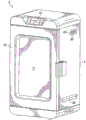
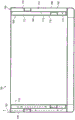
FIG. 1 is a perspective view of an embodiment 2 of the upright electric cooking and smoking apparatus provided by the present invention.
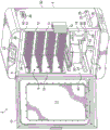
FIG. 2 is a perspective view of the inventive upright electric cooking and smoking machine 2 with the door 10 in an open position to show the interior of the apparatus 2.
Figure 3 is a perspective view of an embodiment 18 of the electrical heating element assembly 14 and smoke box provided by the present invention.
Figure 4 is a cross-sectional elevational side view of the inventive smoke box 18.
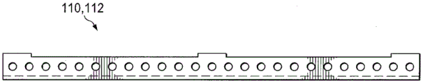
Figure 5 is an elevational side view of the flow rail members 110, 112 used in the inventive smoke box 18.
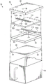
Figure 6 is an exploded view of the inventive smoke box 18.
Figure 7 is a cutaway elevational side view of an alternate embodiment 150 of the inventive smoke box.
Figure 8 is an exploded view of the inventive smoke box 150.
Detailed Description
An embodiment 2 of the vertical electric cooking and smoking machine provided by the present invention is shown in fig. 1 and 2. The inventive electric cooking and smoking device 2 comprises: an upright rectangular box 4 having a vertical front opening 6; a cooking and smoking chamber 8 inside the upright box 4; a vertical front door 10, preferably having a window 11 therein, the vertical front door 10 being pivotally attached to the upright case 4 for opening and sealing closing the front opening 6 of the cooking and smoking chamber 8; a plurality of food holding shelves 12 removably positionable in the cooking and smoking chamber 8; an electric heating element assembly 14 spaced above the floor 16 of the cooking and smoking chamber 8; a smoke box 18 removably positionable on the heating element assembly 14; a removable tray or other container 20 adjacent the heating element assembly 14 for holding water or other liquid to maintain a desired level of moisture or flavorant vapor in the cooking and smoking chamber 8; and an electronic display and control panel 22 at the top of the box 4 above the door 10 for controlling the electric heating system and/or monitoring the temperature, cooking time and/or other parameters within the cooking and smoking chamber 8 in any desired manner.
Preferably, a plurality of food holding racks 12 are mounted on the opposing pressed side panels 15 using the common structure found in indoor ovens for holding cooking racks. However, the pressed detail 15 is not preferably integral with the side walls of the cooking and smoking chamber 8 as is otherwise typical in indoor ovens, but is more preferably attached as a separate part as depicted for additional flexibility in the manufacture and construction of the inventive apparatus 2.
As shown in FIGS. 1 and 2, two air intake vents 24 and 28 are provided in the lower portion of the cooking and smoking chamber 8. One of the lower air intake vents 24 is disposed through a left side wall 30 of the upright box 4 and the other air intake vent 28 is disposed through a right side wall 32 of the upright box 4, preferably directly opposite the left side intake vent 24. The air intake vents 24 and 28 are preferably located in the side walls 30 and 32 at or below the height of the heating element assembly 14.
Each of the side air intake vents 24 and 28 preferably comprises an opening (e.g., an elongated slit) or a series of openings 25 that (a) preferably extend laterally through at least 30% of the width of the side wall 30 or 32 (more preferably from about 75% to about 85% of the width of the side wall 30 or 32) in the side wall 30 or 32 of the upright box 4 and (b) are preferably centrally located in a lower portion of the side wall 30 or 32. Proportionally, the total flow (open) area provided by each of the air intake vents 24 and 28 per 2.94 cubic feet of volume of the cooking and smoking chamber 8 is preferably in the range of from about 1.0 to about 4.0 square inches, more preferably from about 2.0 to about 3.0 square inches. Although it is preferred that the air intake vents 24 and 28 be non-adjustable, the inventive apparatus 2 may alternatively include louvers, sliding covers, or other features for selectively varying the open area of the intake vents 24 and 28.
As further shown in FIGS. 1 and 2, two exhaust vents 34 and 36 are provided in the upper portion of the cooking and smoking chamber 8, preferably above the uppermost food support shelf 12 near the top of the cooking and smoking chamber 8. Preferably, one of the upper exhaust vents 34 is disposed through the left sidewall 30 of the upright tank 4 and the other upper exhaust vent 36 is disposed through the right sidewall 32 of the upright tank 4, preferably directly opposite the left exhaust vent 34.
Each of the exhaust vents 34 and 36 preferably: (a) is positioned from about 1.5 to about 6.5 inches from the upper end of the cooking and smoking chamber 8; (b) is positioned within a range of from about 2.5 to about 4.5 inches from the rear wall 38 of the cooking and smoking chamber 8; (c) having a louvered outer cover 40, the louvered outer cover 40 operative to direct smoke from a front end 94 of the cover assembly 82 of the smoke box 18 up and through the plurality of food holding shelves 12; and (d) providing a total effective proportional flow area through the lid 40 (if present) in the range of from about 4.0 to about 9.0 square inches, more preferably from about 6.0 to about 7.0 square inches per 2.94 cubic feet of volume of the cooking and smoking chamber 8.
The inventive placement of the lower pair of air intake vents 24 and 28 and the upper pair of exhaust vents 34 and 36 on each side of the cooking and smoking chamber 8 creates a balanced flow of ventilation air through the cooking and smoking chamber 8 on both sides, thereby providing a more even distribution of smoke and heat within the chamber 8. The cool, fresh outside air intake also reduced the CO as shown in the testing of inventive device 22And (4) generating. In these tests, the CO of the exhaust from the inventive cooking and smoking chamber 8 was above the space of the first two hours of operation2The concentration does not exceed 0.78%, normally between 0.10% and 0.15%. However, in the absence of air intake vents 24 and 28, CO is generated2Concentrations as high as 2.25%, normally between 1.3% and 2.1%.
Moreover, these tests additionally show that the cooling air flow provided by the inventive ventilation arrangement unexpectedly only slightly reduces the average internal temperature in the cooking and smoking chamber 8 for the first hour of operation, after which the temperature is similar. Although the reason for this surprising result is not known with certainty, it is believed to be the result of the predominant mode of cooking and smoking chamber 8 interior as a whole reaching a state of radiant heat equilibrium after one hour of operation with radiant energy becoming a heat transfer.
The visual effect of the use of the inventive ventilation arrangement with a large fuel load of the type described below is that the smoke of the wood does not become too dark or too rich but retains the desired light grayish blue color. The inventive venting arrangement also reduces the amount of smoke and water vapor condensing on the food surface during cooking.
In addition, the ventilation arrangement reduces the operating pressure within the cooking and smoking chamber 8 and, therefore, in conjunction with the larger size of the smoke box 18 (discussed below) and the inventive design and structure, allows for a much larger (up to as much as four cups or more) load of wood chips, pellets, or other debris to be used in the smoke box 18. Heretofore, in prior single top ventilated electric fume cupboards, the amount of wood chips that could be used in the cupboards was only about 3/4 cups or less due to the pressure caused by the partial combustion of the wood chips and the generation of smoke from the wood chips and the accumulation of unburned combustible hydrocarbons.
Moreover, by providing the lower air intake vents 24 and 28 and the upper exhaust vents 34 and 36 on both sides of the cooking and smoking chamber 8 of the inventive apparatus 2, the cooking and smoking chamber 8 is more uniformly filled with smoke without any voids in the cooking and smoking area. The inventive ventilation arrangement additionally assists in directing smoke upwardly through the food support shelf 12 to uniformly contact and cover the food product in a desired amount of smoke.
The improved electric heating element assembly 14 for use in the inventive vertical electric cooking and smoking machine 2 preferably comprises: a tray 46 having a reflective inner bottom surface 48; one or more electrical heating elements 50 positioned in the tray 46 above the reflective bottom surface 48; a rear accessory bracket 52; and a plurality of bottom legs 53. Rear bracket 52 secures heating element assembly 14 to rear wall 38 of cooking and smoking chamber 8 and provides an air gap between tray 46 and smoke box 18 and rear wall 38 of chamber 8. The bottom legs 53 preferably space the tray 46 about 2.25 inches above the bottom 16 of the cooking and smoking chamber 8. Also, a pair of spacers 54 and 57 project from the sides of the tray 46 for spacing the tray 46 and smoke box 18 from the inner surface of the right side wall 32 of the upright box 4 to provide an air gap of about 0.40 inches.
As seen in fig. 2 and 3, the position of the smoke box 18 relative to the heating element 50 is established with novel and effective features to control the heating of the wood chips or other chips contained in the box 18. This includes a unique retaining station 55 disposed on the tray 46, which retaining station 55 is used to receive the bottom of the smoke box 18 and retain the smoke box 18 above the electrical heating element 50.
The holding table 55 preferably includes: (a) a cover plate 56 at least partially covering the electric heating element 50 and serving as a bottom plate of the holding stage 55; (b) a plurality of spacers (standoffs) 58 protruding from the upper surface of the lid 56 to create an air gap 60 between the surface of the lid 56 and the bottom surface of the smoke box 18; (c) a receiving slot arrangement 65, the receiving slot arrangement 65 comprising two short upright side walls 62 and 64, a short upright rear wall 66 and an open front end 68 for receiving and aligning the bottom of the smoke box 18 on top of the cover plate 56; and (d) a reflective plate 70 extending rearwardly from the top of the short rear wall 66 of the smoke box receiving slot arrangement 65 for shielding the rear of the smoke box 18 from radiant energy emitted or reflected by the heating element 50 and/or the reflective surface 48.
The height of the standoffs 58 above the cover 56 is preferably at least 0.12 inches but no more than 0.25 inches. More preferably, the height of the stand-offs 58 is in the range of from about 0.10 inches to about 0.14 inches. By way of example, and not by way of limitation, the cap plate 56 is preferably formed from aluminized steel, mild steel, stainless steel, ceramic coated decarburized (de-carb) steel, cast iron, or cast aluminum, and the standoffs 58 are preferably formed from aluminized steel, mild steel, stainless steel, ceramic coated decarburized, cast iron, or cast aluminum.
Instead of the use of standoffs 58, a washer, a screw assembly, an extruded turned-over hole, a square extrusion, a plurality of elongated standoffs, for example, in the receiving slot arrangement 65 or in the bottom of the smoke box 18 may alternatively be used to create or provide a space between the cover plate 56 and the bottom of the smoke box 18.
In the inventive upright cooking and smoking device 2, a cover plate 56 that acts as a shield over the heating element 50, spacers (stand-offs) 58 that elevate the bottom of the smoke box 18 away from the cover plate 56, spacers 54 and 57 that provide an air gap between the sides of the smoke box 18 and the inside walls of the cooking and smoking chamber 8, and a rear reflector 70 that shields the rear of the smoke box 18 work together to: (a) sufficiently reduce the temperature and heat transfer at the bottom of the smoke box 18 to increase the smoking time; (b) providing uniform heating at the bottom of the smoke box 18 so that the entire lower bed of wood chips in the box 18 will start at the same time; and (c) eliminating hot pockets within the smoke box 18.
An embodiment 18 of the inventive smoke generating box for use in the upright electric cooking and smoking device 2 is illustrated in fig. 3-6. The inventive smoke box 18 comprises: a rectangular box 75 having a longitudinal axis 76; a front handle 78; a cold plate or "false bottom" 80 that fits within the rectangular box 75; and a removable cover assembly 82. The false bottom 80 has a pair of downwardly extending side spacer rails 84 and 86 that support and space the false bottom 80 above the bottom 81 of the tank 75 to provide an air gap 88 between the false bottom 80 and the true bottom 81 of the tank 75 of from about 0.20 inches to about 0.50 inches, more preferably from about 0.33 inches to about 0.38 inches. This additional air gap 88 in the bottom of the box 75 operates to further stabilize the heating of the wood chips or other wood chips in the smoke box 18.
The rectangular box 75 will preferably be sized to hold at least four cups of wood chips or other debris above the false bottom 80. The interior of the rectangular box 75 will preferably have: (a) a longitudinal length in a range from about 6.0 inches to about 6.25 inches; (b) a width in a range from about 4.25 inches to about 4.40 inches; and (c) a height in the range of from about 3.0 inches to about 3.25 inches.
The lid assembly 82 of the inventive smoke generating box 18 comprises: (a) a lower cover member 90, the lower cover member 90 having a row of transverse smoke ports 92 extending through the lower cover member 90 adjacent a front end 94 of the cover member 82; (b) an upper cover 96, the upper cover 96 having a row of transverse smoke ports 98 extending through the upper cover 96 adjacent the front end 94 of the cover assembly 82; (c) a middle cover 100 positioned between the upper cover 96 and the lower cover 90, the middle cover 100 having a row of lateral smoke ports 102 extending through the middle cover 100 adjacent a rear end 104 of the cover assembly 82; (d) a lower horizontal flow gap 106 formed between the lower cover 90 and the middle cover 100; (e) an upper horizontal flow gap 108 formed between the middle cap 100 and the upper cap 96; (f) a lower flow rail member 110 extending laterally in the lower flow gap 106; and (g) an upper flow rail member 112 extending laterally in the upper flow gap 108.
Each of the laterally extending upper and lower flow rail members 110 and 112 includes a pair of parallel pass-through rails 110a and 110b and 112a and 112b that extend laterally across and block the upper and lower horizontal flow gaps 106 and 108. The upstream rail 110a, 112a of each rail member 110, 112 has a series of smoke inlet apertures 114, 116 disposed therethrough. The downstream tracks 110b, 112b of each track member 110, 112 have a series of smoke outlet apertures 118, 120 disposed therethrough. Preferably, the smoke outlet apertures 118, 120 of each rail member 110, 112 are not aligned with the smoke inlet apertures 114, 116 of the rail members 110, 112. Thus, smoke flowing into the inlet apertures 114, 116 cannot flow directly (e.g., in a straight line) through the outlet apertures 118, 120, but instead is forced to change direction at least to some extent within the rail members 110, 112.
The lower track member 110 is preferably positioned in the lower flow gap 106 at a distance from the inlet end 122 to the outlet end 124 of the lower flow gap 106 of from about 1/3 to about 4/5, more preferably from about 1/2 to about 3/4. Similarly, the upper track member 112 is preferably positioned in the upper flow gap 108 at a distance from the inlet end 126 to the outlet end 128 of the upper flow gap 108 of from about 1/3 to about 4/5, more preferably from about 1/2 to about 3/4.
For each of the lower cover 90, upper cover 96 and middle cover 100, the total proportional flow area of the smoke ports of the respective row 92, 98 or 102 disposed therethrough will preferably be in the range of from about 0.9 to about 2.6 square inches, more preferably from about 1.3 to about 1.6 square inches per 80 cubic inch of volume of the cooking and smoking chamber 18.
The lower flow gap 106 and the upper flow gap 108 formed between the covers will preferably each have a height in the range of from about 0.10 to about 0.17 inches, more preferably from about 0.12 to about 0.15 inches.
The total proportional flow area of the smoke inlet or smoke outlet apertures 114, 116, 118, or 120 disposed through each of the separate upstream and downstream tracks 110a, 110b, 112a, or 112b of the track members 110 and 112 will preferably be in the range of from about 0.25 to about 1.0 square inches, more preferably from about 0.44 to about 0.62 square inches, per 80 cubic inches of volume of the cooking and smoking chamber 18. For each of the track members 110 and 112, the distance between its upstream track 110a, 112a and downstream track 110b, 112b will preferably be in the range of from about 0.25 to about 0.50 inches, more preferably from about 0.36 to about 0.40 inches.
In the inventive smoke box 18, smoke produced by the wood chips in the heating box 75 is forced to flow along a defined circuitous flow path 130 in which the smoke travels into the smoke port 92 of the lower cover member 90, through the first portion of the lower horizontal flow gap 106 to the lower track member 110, through the offset apertures 110a and 110b of the lower track member, from the lower track member 110 to the smoke port 102 of the middle cover member 100, through the first portion of the upper horizontal flow gap 108 to the upper track member 112, through the offset apertures 112a and 112b of the upper track member 112, from the upper track member 112 to the smoke port 98 of the upper cover member 96, and out of the smoke port 98 into the cooking and smoking chamber 2 of the inventive vertical electrical appliance.
This circuitous path 130 acts as a flame suppression mechanism to prevent and contain any fire in the smoke box and additionally provides cooling and mixing of the generated smoke in the inventive smoke box 18 so that the smoke exiting the lid outlet opening 98 has a relatively uniform temperature and smoke concentration. The length of the circuitous path 130 also allows the temperature of the smoke to be hot enough to maintain the smoke particles suspended in the atmosphere, but cold enough to remain well below any ignition point as the smoke exits the smoke box 18.
An alternative embodiment 150 of the inventive smoke box is illustrated in figures 7 and 8. The inventive smoke box 150 is substantially identical to the inventive smoke box 18, except that instead of providing a circuitous exit path for smoke through the lid of the box, a substantially similar flow path 152 is provided in one, two, three or all four of the vertical sides 154, 156, 158, 160 of the inventive smoke box 150.
In the inventive smoke box 150, each of the one or more vertical sides in which the circuitous smoke exit path 152 is disposed comprises: (a) an inner vertical wall 162 having a discharge port 164, the discharge port 164 extending across an upper end portion of the inner vertical wall 162; (b) an outer vertical wall 166 having an open upper end 168; (c) a middle vertical wall 170 positioned between the inner vertical wall 162 and the outer vertical wall 166 and having a discharge outlet 175, the discharge outlet 175 extending across a bottom portion of the middle vertical wall 170; (d) an inner vertical flow gap 172 formed between the inner vertical wall 162 and the middle vertical wall 170; (e) an outer vertical flow gap 174 formed between the middle vertical wall 170 and the outer vertical wall 166; (f) an inner flow rail member 176 extending horizontally in the inner flow gap 172; (g) an outer flow rail member 178 extending horizontally in the outer vertical flow gap 174; and (h) a row of smoke evacuation ports 180 formed through the top of the lid 182 of the bin along the edge of the lid 182 for placement over the open upper end 168 of the outer vertical wall 166.
Thus, in the circuitous flow path 152 defined in the inventive smoke box 150, smoke is forced to flow into the smoke ports 164 at the upper end of the inner vertical wall 162, downwardly through the inner flow gap 172 to the inner track member 176, from the inner track member 176 to the flow ports at the bottom of the middle vertical wall 170, upwardly through the outer vertical flow gap 174 to the outer track member 178, and from the outer track member 178 to the smoke outlet 180 of the lid 182 and out of the smoke outlet 180 of the lid 182. Alternatively, the smoke may exit through a side exhaust provided at the upper end of the outer wall 166 rather than through the lid 182.
The flow port areas for the walls and lid of the circuitous flow path 152 of the inventive smoke box 150, the rail member flow port areas, and the flow gap widths will preferably be the same as those of the flow path 130 provided in the lid assembly of the inventive smoke box 18.
Accordingly, the present invention is well adapted to carry out the objects and attain the ends and advantages mentioned as well as those inherent therein. Although a presently preferred embodiment has been described for purposes of this disclosure, many variations and modifications will be apparent to those of ordinary skill in the art. Such changes and modifications are intended to be included within the scope of the present invention.
Claims (21)
1. An apparatus for cooking and smoking food, comprising:
a vertically extending cooking and smoking chamber having a left side wall, a right side wall, a rear wall, a front opening, and a floor;
a door positionable over the front opening for closing and opening the front opening;
a smoke box housed in said cooking and smoking chamber, said smoke box comprising:
the container is a container, and the container is a container,
a cover that can be placed over the container,
an inner combustion zone in the vessel for combusting wood chips or other debris in an oxygen deficient environment to produce smoke, and
an exhaust flow assembly in the lid and/or in one or more vertical sidewalls of the container, wherein the exhaust flow assembly defines a circuitous exhaust flow path for smoke, wherein smoke must flow in a first direction from an inlet end to an outlet end of an inner flow gap formed by the exhaust flow assembly, and then must flow in a second direction different from the first direction from the inlet end to the outlet end of an outer flow gap formed by the exhaust flow assembly.
2. The apparatus of claim 1, wherein the apparatus further comprises two air intake vents and two exhaust vents, wherein a first of the air intake vents is disposed through a lower portion of the right sidewall, a second of the air intake vents is disposed through a lower portion of the left sidewall, a first of the exhaust vents is disposed through an upper portion of the right sidewall, and a second of the exhaust vents is disposed through an upper portion of the left sidewall.
3. The apparatus of claim 2, wherein:
the first air intake vent includes one or a series of openings extending horizontally across at least 30% of the horizontal width of the right sidewall, and
the second air intake vent includes one or a series of openings extending horizontally across at least 30% of the horizontal width of the left sidewall.
4. The apparatus of claim 2 wherein said first air intake vent and second air intake vent each have an open flow area in the range of from 1.0 to 4.0 square inches per 2.94 cubic feet of volume of said cooking and smoking chamber.
5. The apparatus of claim 4, wherein the first and second exhaust vents each have a flow area in a range from 4.0 to 9.0 square inches per 2.94 cubic feet of volume of the cooking and smoking chamber.
6. The apparatus of claim 5, wherein the first and second exhaust vents each have a louvered cover.
7. The apparatus of claim 2, wherein:
the cooking and smoking chamber has an uppermost food support shelf positioned therein, and
the first and second exhaust vents are positioned at a height above a height of the uppermost food support rack.
8. The apparatus of claim 1, wherein the apparatus further comprises:
one or more electric heating elements in the cooking and smoking chamber, and
a holding stage comprising:
a cover plate at least partially covering the one or more electric heating elements, and
a plurality of spacers protruding from an upper surface of a lid plate, the smoke box being placeable on the plurality of spacers to provide an air gap between the upper surface of the lid plate and a bottom surface of the smoke box.
9. The apparatus of claim 1, wherein the smoke box
Further comprising:
the container has a true bottom with no opening therethrough, an
A false bottom in the interior of the container, the false bottom being spaced above the true bottom of the container such that a bottom air space is defined in the container between the false bottom and the true bottom of the container, the false bottom having no openings therethrough.
10. The apparatus of claim 1, wherein the smoke box further comprises:
a first flow track member extending laterally within the inner flow gap, the first flow track member at least temporarily altering an exhaust flow path of the smoke as the smoke travels from the inlet end to the outlet end of the inner flow gap, an
A second flow track member extending laterally in the outer flow gap, the second flow track member at least temporarily altering the exhaust flow path of the smoke as the smoke travels from the inlet end to the outlet end of the outer flow gap.
11. The apparatus of claim 10, wherein the first and second flow rail members each comprise an upstream rail and a parallel downstream rail, the upstream and downstream rails each having a plurality of apertures for smoke flow, wherein the apertures in the downstream rail are not aligned with the apertures in the upstream rail.
12. The apparatus of claim 10, wherein the exhaust flow assembly is formed in a lid of the smoke box.
13. The apparatus of claim 10, wherein the exhaust flow assembly is formed in one of the one or more vertical sidewalls of the smoke box.
14. The apparatus of claim 10, wherein the exhaust flow assembly is formed in a plurality of vertical sidewalls of the smoke box.
15. A smoke box apparatus, comprising:
a vessel having an inner combustion zone for combusting wood chips or other debris in an oxygen deficient environment to produce smoke,
a cap capable of being placed on the container, an
An exhaust flow assembly in the lid and/or in one or more vertical sidewalls of the container, wherein the exhaust flow assembly defines a circuitous exhaust flow path for smoke, wherein smoke must flow in a first direction from an inlet end to an outlet end of an inner flow gap formed by the exhaust flow assembly, and then must flow in a second direction different from the first direction from the inlet end to the outlet end of an outer flow gap formed by the exhaust flow assembly.
16. The smoke box apparatus of claim 15 wherein the container has a true bottom without openings therethrough and a false bottom inside the container, the false bottom being spaced above the true bottom of the container such that a bottom air space is defined in the container between the false bottom and the true bottom of the container, the false bottom having no openings therethrough.
17. The smoke box apparatus of claim 15 wherein the smoke box apparatus further comprises:
a first flow track member extending laterally within the inner flow gap, the first flow track member at least temporarily altering an exhaust flow path of the smoke as the smoke travels from the inlet end to the outlet end of the inner flow gap, an
A second flow track member extending laterally in the outer flow gap, the second flow track member at least temporarily altering the exhaust flow path of the smoke as the smoke travels from the inlet end to the outlet end of the outer flow gap.
18. The smoke box apparatus of claim 17 wherein the first and second flow track members each comprise an upstream track and a parallel downstream track, the upstream and downstream tracks each having a plurality of apertures for smoke flow, wherein the apertures in the downstream track are not aligned with the apertures in the upstream track.
19. The smoke box apparatus of claim 17 wherein the exhaust flow assembly is formed in a lid of the container.
20. The smoke box apparatus of claim 17 wherein the exhaust flow assembly is formed in one of the one or more vertical sidewalls of the container.
21. The smoke box apparatus of claim 17 wherein the exhaust flow assembly is formed in a plurality of vertical side walls of the container.
Applications Claiming Priority (3)
| Application Number | Priority Date | Filing Date | Title |
|---|---|---|---|
| US201562138002P | 2015-03-25 | 2015-03-25 | |
| US62/138002 | 2015-03-25 | ||
| PCT/US2016/023419 WO2016154114A1 (en) | 2015-03-25 | 2016-03-21 | Vertical electric cooker and smoker and smoke box |
Publications (2)
| Publication Number | Publication Date |
|---|---|
| CN107683091A CN107683091A (en) | 2018-02-09 |
| CN107683091B true CN107683091B (en) | 2021-09-03 |
Family
ID=56977739
Family Applications (1)
| Application Number | Title | Priority Date | Filing Date |
|---|---|---|---|
| CN201680017847.8A Active CN107683091B (en) | 2015-03-25 | 2016-03-21 | Vertical electric cooking and smoking machine and smoke box |
Country Status (6)
| Country | Link |
|---|---|
| US (1) | US10426176B2 (en) |
| EP (1) | EP3273786B8 (en) |
| CN (1) | CN107683091B (en) |
| CA (1) | CA2977120C (en) |
| DK (1) | DK3273786T3 (en) |
| WO (1) | WO2016154114A1 (en) |
Families Citing this family (21)
| Publication number | Priority date | Publication date | Assignee | Title |
|---|---|---|---|---|
| US10595540B1 (en) * | 2015-05-01 | 2020-03-24 | David B. Knight & Associates, Inc. | Barbecue oven having circulation control |
| EP3104086B1 (en) * | 2015-06-11 | 2019-09-18 | Electrolux Professional S.p.A. | Flavoring device for use in a cooking chamber |
| EP3104085A1 (en) * | 2015-06-11 | 2016-12-14 | Electrolux Professional S.p.A. | Flavoring device for use in a cooking chamber |
| US10045546B2 (en) * | 2016-02-18 | 2018-08-14 | Masterbuilt Manufacturing, Llc | Electric food smoker |
| CN110250930A (en) | 2017-08-09 | 2019-09-20 | 沙克忍者运营有限责任公司 | Cooking system |
| US10624358B2 (en) * | 2017-12-05 | 2020-04-21 | Lem Products Holding Llc | Electric smoker |
| USD914447S1 (en) | 2018-06-19 | 2021-03-30 | Sharkninja Operating Llc | Air diffuser |
| USD883014S1 (en) | 2018-08-09 | 2020-05-05 | Sharkninja Operating Llc | Food preparation device |
| USD883015S1 (en) | 2018-08-09 | 2020-05-05 | Sharkninja Operating Llc | Food preparation device and parts thereof |
| USD903413S1 (en) | 2018-08-09 | 2020-12-01 | Sharkninja Operating Llc | Cooking basket |
| USD934027S1 (en) | 2018-08-09 | 2021-10-26 | Sharkninja Operating Llc | Reversible cooking rack |
| CN212788226U (en) | 2019-02-25 | 2021-03-26 | 沙克忍者运营有限责任公司 | Cooking system |
| US20190254476A1 (en) | 2019-02-25 | 2019-08-22 | Sharkninja Operating Llc | Cooking device and components thereof |
| USD918654S1 (en) | 2019-06-06 | 2021-05-11 | Sharkninja Operating Llc | Grill plate |
| USD982375S1 (en) | 2019-06-06 | 2023-04-04 | Sharkninja Operating Llc | Food preparation device |
| CA3153065A1 (en) | 2019-07-15 | 2021-01-21 | Sharkninja Operating Llc | Multiple compartment countertop cooking system |
| CN110915877B (en) * | 2019-12-27 | 2021-11-19 | 广东美的厨房电器制造有限公司 | Cooking appliance control method and device and cooking appliance |
| US11647861B2 (en) | 2020-03-30 | 2023-05-16 | Sharkninja Operating Llc | Cooking device and components thereof |
| US20220007662A1 (en) * | 2020-07-07 | 2022-01-13 | Zhejiang Fudeer Electric Appliance Co., Ltd. | Smoking Oven |
| IT202000026765A1 (en) * | 2020-11-10 | 2022-05-10 | Costruzioni Mecc Paterno S R L | SMOKING AND COOKING APPARATUS |
| US20220202027A1 (en) | 2020-12-30 | 2022-06-30 | Sharkninja Operating Llc | Smoke functionality in electric grill-type appliance |
Citations (13)
| Publication number | Priority date | Publication date | Assignee | Title |
|---|---|---|---|---|
| US4307659A (en) * | 1978-03-31 | 1981-12-29 | Mtm Corporation | Barbecue oven |
| CN2036387U (en) * | 1988-10-17 | 1989-04-26 | 丁士来 | Casing type water-boiling kettle |
| US4924071A (en) * | 1987-07-06 | 1990-05-08 | Woodroast Systems, Inc. | Oven |
| US4934260A (en) * | 1989-09-08 | 1990-06-19 | Blevins Mack F | Food cooker and smoker |
| JPH02255039A (en) * | 1989-03-28 | 1990-10-15 | Tsu Kikai Kigu Kogyo Kyodo Kumiai | Smoking system |
| US5588355A (en) * | 1995-04-17 | 1996-12-31 | Mead; Julian E. | Knockdown compactable food smoker and method of use thereof |
| US5782165A (en) * | 1992-09-01 | 1998-07-21 | Ever Splendor Enterprises Co., Ltd. | Multi-purpose cooking apparatus |
| CN2405523Y (en) * | 1999-12-22 | 2000-11-15 | 昕昌兴企业股份有限公司 | Electronic safety meat roaster |
| CN2544532Y (en) * | 2002-03-26 | 2003-04-16 | 广东德豪润达电气股份有限公司 | Electric heating device with smoking function |
| CN2811800Y (en) * | 2005-06-08 | 2006-08-30 | 何均奇 | Environment-friendly smoke exhausting and purifying device |
| CN202311122U (en) * | 2011-11-24 | 2012-07-11 | 王朝晖 | Low-temperature smoke generator |
| CN103960989A (en) * | 2013-02-05 | 2014-08-06 | 阿尔菲尼迪美国有限责任公司 | Apparatus For Cooking And Smoking Food |
| CN204047818U (en) * | 2014-09-25 | 2014-12-31 | 松阳县诚天和食品有限公司 | A kind of bacon machine |
Family Cites Families (132)
| Publication number | Priority date | Publication date | Assignee | Title |
|---|---|---|---|---|
| US1399704A (en) | 1921-12-06 | Cooking-stove | ||
| GB191423552A (en) | 1911-12-04 | 1915-03-18 | South Metropolitan Gas Co | Improvements in Gas Ovens. |
| US1158986A (en) | 1914-02-21 | 1915-11-02 | Carl G Cronwall | Gas-burner. |
| US2001615A (en) | 1932-01-19 | 1935-05-14 | Karten William Theodore | Baking vessel |
| GB432481A (en) | 1933-02-23 | 1935-07-22 | Bolinder Fabriks Aktiebolag | Improvements in or relating to cooking stoves |
| GB562136A (en) | 1942-11-18 | 1944-06-20 | Herbert Gordon Darby | Improvements in gas cooking stoves |
| GB576377A (en) | 1944-04-14 | 1946-04-01 | James Forbes Jones | An improved gas-heated oven stove |
| FR1129123A (en) | 1955-07-13 | 1957-01-16 | Liotard Metallurg | Gas heater, emitter of red and infrared rays |
| CH371237A (en) | 1957-10-24 | 1963-08-15 | Pozzi Arnaldo | Gas burner with a radiator |
| US3277948A (en) | 1960-09-09 | 1966-10-11 | Thermal Engineering Corp | Radiant burner utilizing flame quenching phenomena |
| US3155814A (en) | 1961-07-31 | 1964-11-03 | Radiant Electronic Products Co | Infrared radiant heating oven |
| FR1387132A (en) | 1962-12-11 | 1965-01-29 | Hupp Corp | Improvement in infrared radiation heating |
| US3245458A (en) | 1962-12-11 | 1966-04-12 | Hupp Corp | Radiant gas burner |
| US3437415A (en) | 1966-08-22 | 1969-04-08 | Graig & Seeley Ltd | Radiant gas burner |
| US3517602A (en) * | 1968-07-08 | 1970-06-30 | James P Horton | Barbecue cooker |
| US3561902A (en) | 1968-09-19 | 1971-02-09 | Willie H Best | Radiant burner |
| US3586825A (en) | 1968-10-03 | 1971-06-22 | Modern Maid Inc | Flush top cooking unit with ventilating means |
| US3663798A (en) | 1969-08-25 | 1972-05-16 | Thermo Electron Corp | An infrared heating surface |
| US3683058A (en) | 1969-08-25 | 1972-08-08 | Maurice Partiot | Infrared burners and high efficiency radiant plates |
| FR2076610A5 (en) | 1970-01-21 | 1971-10-15 | Gestion Immob Mob | |
| US3788301A (en) | 1972-07-31 | 1974-01-29 | R Terry | Smoke generator |
| US3941117A (en) | 1974-10-21 | 1976-03-02 | Owens-Illinois, Inc. | Cooktop for a gas-fired range |
| US4024839A (en) | 1975-03-10 | 1977-05-24 | Columbia Gas System Service Corporation | Gas-fired smooth top range |
| US4057670A (en) | 1976-01-28 | 1977-11-08 | Jenaer Glaswerk Schott & Gen. | Cooking surfaces of glass-ceramic plates with layers with different values for radiation transmission |
| US4039275A (en) | 1976-02-23 | 1977-08-02 | Mcgettrick Charles A | Infrared energy generator with orifice plate |
| JPS5343025U (en) | 1976-09-18 | 1978-04-13 | ||
| US4207456A (en) | 1977-11-04 | 1980-06-10 | Best Willie H | Electrical infrared radiant heater |
| US4235023A (en) | 1978-06-16 | 1980-11-25 | Best Willie H | High heat transfer oven |
| US4426792A (en) | 1978-06-16 | 1984-01-24 | Best Willie H | High turbulance heat transfer oven |
| US4546553B1 (en) | 1978-06-16 | 1993-04-13 | Radiant wall oven and process of drying coated objects | |
| US4276869A (en) | 1979-04-16 | 1981-07-07 | Kern Eugene F | Barbecue grill slab |
| US4403541A (en) | 1979-05-29 | 1983-09-13 | Ducane Heating Corporation | Heat trapping cooking grill |
| FI61562C (en) | 1979-12-14 | 1982-08-10 | Jorma Wallasvaara | SPIS |
| US4321857A (en) | 1980-04-08 | 1982-03-30 | Best Willie H | Infrared gas grill |
| US4403597A (en) | 1981-01-16 | 1983-09-13 | Miller Don J | Heat transfer device |
| US4437833A (en) | 1981-03-05 | 1984-03-20 | Red-Ray Manufacturing Company, Inc. | Infrared radiating burner article |
| WO1982003544A1 (en) | 1981-04-10 | 1982-10-28 | Keith Edward Berg | Self cleaning indoor barbecue griller |
| SE8200685L (en) | 1982-02-05 | 1983-08-06 | Electrolux Ab | WITH INFRARED RADIATION WORKING HOUSE OVEN |
| FR2534353A1 (en) | 1982-10-11 | 1984-04-13 | Vaneecke Solaronics | ALVEOLED RADIANT FACING PLATE FOR RADIANT BURNER |
| US4537492A (en) | 1983-07-07 | 1985-08-27 | Itek Corporation | Heater-drier for fusing toner images on wet printing plates |
| IT1214334B (en) | 1983-11-30 | 1990-01-10 | Dario Bernardi | GRILL FOR THE COOKING OF REFLECTED HEATS |
| US4715356A (en) | 1985-07-26 | 1987-12-29 | Reynolds Howard S | Gas burner with heat reflective radiants for controlled heat concentration |
| GB8526068D0 (en) | 1985-10-22 | 1985-11-27 | Thorn Emi Appliances | Cooking apparatus |
| JPH0663625B2 (en) | 1986-09-24 | 1994-08-22 | 株式会社日本ケミカル・プラント・コンサルタント | Far infrared radiation device |
| US4785552A (en) | 1987-07-08 | 1988-11-22 | Best Willie H | Convection stabilized radiant oven |
| JPH0625919Y2 (en) | 1988-03-15 | 1994-07-06 | 千住金属工業株式会社 | Infrared heater |
| US4839502A (en) | 1988-03-21 | 1989-06-13 | Swanson David L | Cooking apparatus |
| US4889972A (en) | 1988-08-11 | 1989-12-26 | Chang Chia C | Multi-functional electrically activated stove |
| US4886044A (en) | 1988-08-17 | 1989-12-12 | Best Willie H | Infrared gas grill |
| US4909137A (en) | 1988-11-28 | 1990-03-20 | Giuliano Brugnoli | Cooking grill grease catcher |
| CA2005415C (en) | 1989-01-10 | 1994-03-01 | Willie H. Best | High efficiency gas burner assembly |
| US4979436A (en) | 1989-01-23 | 1990-12-25 | Mcgowan Michael J | Smoking and baking apparatus |
| US5230161A (en) | 1989-03-28 | 1993-07-27 | Haden Schweitzer Corporation | Apparatus and process for generating radiant energy |
| DE3912124C1 (en) | 1989-04-13 | 1990-07-12 | Schott Glaswerke, 6500 Mainz, De | |
| US4960977A (en) | 1989-04-20 | 1990-10-02 | G. S. Blodgett Co., Inc. | Infra-red baking oven |
| US4883423A (en) | 1989-05-08 | 1989-11-28 | Carrier Corporation | Method for making an infrared burner |
| US5761990A (en) | 1989-06-30 | 1998-06-09 | Stewart, Deceased; James M. | Barbecue cooker apparatus and process |
| US5062408A (en) | 1990-04-19 | 1991-11-05 | Middleby Corporation | Charbroiler |
| US5277106A (en) | 1990-07-02 | 1994-01-11 | The Thermos Company, Inc. | Easily assembled barbecue grill with heat distribution plate |
| US5218952A (en) | 1990-10-29 | 1993-06-15 | Neufeldt Allen A | Radiant heating apparatus |
| US5594999A (en) | 1991-05-15 | 1997-01-21 | Haden Schweitzer Corporation | Radiant wall oven and process for generating infrared radiation having a nonuniform emission distribution |
| US5111803A (en) | 1991-07-03 | 1992-05-12 | Barbecue Innovations Incorporated | Flare reduction buffer for gas barbecues |
| SE468876B (en) | 1991-07-08 | 1993-04-05 | Staalhane Henrik | DEVICE ON GAS OIL GRILL |
| US5322007A (en) | 1991-08-15 | 1994-06-21 | Heat And Control, Inc. | Compact, high-capacity oven |
| US5240411A (en) | 1992-02-10 | 1993-08-31 | Mor-Flo Industries, Inc. | Atmospheric gas burner assembly |
| US5306138A (en) | 1992-03-10 | 1994-04-26 | Best Willie H | Method and apparatus for incinerating combustibles carried by an air stream |
| US5279277A (en) | 1992-08-03 | 1994-01-18 | Barker Gordon R | Heat radiating element and drippings shield for gas-fired barbecues |
| AU673831B2 (en) | 1992-09-29 | 1996-11-28 | Thermos Company, The | Lifestyle barbecue grill |
| US5320086A (en) | 1993-02-16 | 1994-06-14 | Majco Building Specialties, L.P. | Direct vent gas appliance with vertical and horizontal venting |
| DE4326945C2 (en) | 1993-08-11 | 1996-10-24 | Schott Glaswerke | Control device for the gas supply to a gas cooking device with gas radiation burners arranged under a continuous cooking surface |
| US5313877A (en) | 1993-09-21 | 1994-05-24 | Holland Robert B | Barbecue grill with controlled heat distribution |
| US5567459A (en) | 1993-10-12 | 1996-10-22 | Centro De Investigacion Y De Estudios Avanzados-Del I.P.N. | Method of cooking corn dough tortillas using infrared radiation |
| US5711661A (en) | 1994-05-03 | 1998-01-27 | Quantum Group, Inc. | High intensity, low NOx matrix burner |
| US5488897A (en) | 1994-05-11 | 1996-02-06 | Griller's World Inc. | Cooking apparatus |
| US5599471A (en) | 1994-06-13 | 1997-02-04 | Zaidman; Mikhail | Compact smoking oven |
| US5494003A (en) | 1994-09-01 | 1996-02-27 | Alzeta Corporation | Water heater with perforated ceramic plate infrared burner |
| US5566607A (en) | 1995-05-11 | 1996-10-22 | Schleimer; Norman | Grill with grease deflector assembly |
| US6213757B1 (en) | 1995-06-07 | 2001-04-10 | Quantum Group Inc. | Advanced emissive matrix combustion |
| US5676043A (en) | 1995-10-03 | 1997-10-14 | Best; Willie H. | Griddle assembly having discrete cooking zones |
| US5513623A (en) | 1995-10-13 | 1996-05-07 | Hong; Young P. | Portable gas cooking device |
| US5890422A (en) | 1996-06-24 | 1999-04-06 | Grill-N-Roast, Inc. | Convertible drip pan and method of using the same |
| US5879154A (en) | 1996-11-18 | 1999-03-09 | Rheem Manufacturing Company | Flame spreader-type fuel burner with lowered NOx emissions |
| US5989013A (en) | 1997-01-28 | 1999-11-23 | Alliedsignal Composites Inc. | Reverberatory screen for a radiant burner |
| US5782166A (en) | 1997-02-25 | 1998-07-21 | Lin; Charlotte | Structure of grilling apparatus |
| US5823099A (en) | 1998-03-18 | 1998-10-20 | Ko; Li-Sheng | Grill |
| CN1240910A (en) | 1998-04-06 | 2000-01-12 | 达科尔公司 | Electric cooking oven with infrared gas broiler |
| US5909533A (en) | 1998-04-06 | 1999-06-01 | Dacor, Inc. | Electric cooking oven with infrared gas broiler |
| US6035770A (en) * | 1998-05-22 | 2000-03-14 | Whitefield; Robert | Barbecuing and smoking device |
| WO2000001286A1 (en) | 1998-07-02 | 2000-01-13 | Best Willie H | Heating assembly and cooking apparatus |
| JP2000121064A (en) | 1998-10-19 | 2000-04-28 | Matsushita Electric Ind Co Ltd | High-frequency heating device |
| GB9827620D0 (en) | 1998-12-16 | 1999-02-10 | Bray Burners Ltd | Gas burner |
| GB9902805D0 (en) | 1999-02-10 | 1999-03-31 | Trianco Redfyre | Heat storage range cooker |
| US6190162B1 (en) | 1999-02-11 | 2001-02-20 | Marsden, Inc. | Infrared heater and components thereof |
| US6205996B1 (en) | 1999-09-14 | 2001-03-27 | John Patrick Ryan | Barbecue grill with radiant fire grate |
| FR2799632B3 (en) | 1999-10-14 | 2001-11-23 | Hameur Sa | TOASTER |
| FR2800444B1 (en) | 1999-10-29 | 2002-03-08 | Ct D Etude Et De Realisation D | OVERHEAD HEAT TRANSMITTER WITH INFRARED AND LIGHT GAS RADIATION IN PARTICULAR FOR VERY LOW PRESSURE SUPPLY |
| GB0007733D0 (en) | 2000-03-31 | 2000-05-17 | Glynwed Consumer & Foodservice | An heating appliance |
| WO2002013663A2 (en) | 2000-08-11 | 2002-02-21 | W.C. Bradley Company | Portable barbecue grill |
| JP2002206713A (en) | 2001-01-10 | 2002-07-26 | Tokyo Gas Co Ltd | Flat heating surface type gas cooker |
| US6761160B1 (en) | 2001-05-17 | 2004-07-13 | Lawton Haygood | Hollow walled solid fuel grill |
| US6779519B2 (en) | 2001-09-22 | 2004-08-24 | Uwe Harneit | Cover sheet for rotisserie burners |
| DE10215688A1 (en) | 2002-04-10 | 2003-11-06 | Schott Glas | Gas burner, especially for living flame fireplaces, contains pot shaped gas trap region to eliminate humming and buzzing sounds |
| DK1521540T3 (en) | 2002-06-25 | 2009-02-02 | Jetboil Inc | heating tank |
| US6783226B2 (en) | 2002-09-26 | 2004-08-31 | Xerox Corporation | Curved infrared foil heater for drying images on a recording medium |
| JP2004179089A (en) | 2002-11-28 | 2004-06-24 | Sanei Denki Seisakusho:Kk | Separable reflection type heating device using ring heater |
| US20040152028A1 (en) | 2003-02-05 | 2004-08-05 | Singh Prem C. | Flame-less infrared heater |
| US7307243B2 (en) | 2003-05-09 | 2007-12-11 | North Carolina State University | Dynamic radiant food preparation methods and systems |
| WO2004103133A1 (en) | 2003-05-23 | 2004-12-02 | Linigo Ltd | Portable anti-spill single gas burner camp stove |
| US7426885B2 (en) | 2004-12-23 | 2008-09-23 | Mclemore Don | Cooking device |
| US7219663B2 (en) | 2003-09-05 | 2007-05-22 | Islander Innovations Llc | Kit, apparatus and method for use in cooking over an intense heat source |
| GB0327972D0 (en) | 2003-12-03 | 2004-01-07 | Aga Consumer Products Ltd | Improvements in and relating to stoves |
| US7451691B2 (en) | 2004-03-16 | 2008-11-18 | Robertson Michael L | No waste cooking oven with multiple cooking functions |
| US7202447B2 (en) | 2004-04-02 | 2007-04-10 | Kingdon Charles J | Conveyor type oven |
| KR100583386B1 (en) | 2004-04-12 | 2006-05-25 | 주식회사 에취알에스 | coffee bean roasting method and coffee bean roasting apparatus |
| WO2006009932A1 (en) | 2004-06-23 | 2006-01-26 | Best Willie H | Infrared emitting apparatus |
| US7337707B2 (en) | 2004-08-27 | 2008-03-04 | Jesus Antonio Silvestrini | Thermal conditioning system having continuous conveyor |
| KR100543886B1 (en) | 2005-05-27 | 2006-01-23 | 반석제로파 주식회사 | Ceramic powder emitting far infrared ray and manufacturing method of a high-density physical therapy stone thereby |
| US7810487B2 (en) | 2005-12-01 | 2010-10-12 | W.C. Bradley Company | Apparatus and methods for providing an improved cooking grate for an outdoor cooking grill |
| US7681493B2 (en) | 2005-12-08 | 2010-03-23 | Moore Nathan E | Outdoor smoking system |
| DK2091396T3 (en) | 2006-09-26 | 2011-02-21 | Char Broil Llc | Cooker with concave beam sensor |
| EP2084460B1 (en) | 2006-11-10 | 2011-10-26 | Char-Broil, LLC | Radiant tube broiler |
| US20080163765A1 (en) * | 2007-01-05 | 2008-07-10 | O'shea Gerald M | Apparatus, system, and method for producing flavored smoke on an outdoor grill |
| AU2008238342B2 (en) | 2007-04-16 | 2014-07-31 | Aktiebolaget Electrolux | Improved barbecue and barbecue components |
| USD615798S1 (en) | 2009-01-05 | 2010-05-18 | Mclemore Don | Smoker |
| US8399810B2 (en) | 2009-08-11 | 2013-03-19 | W. C. Bradley Co. | Electric patio bistro |
| WO2012097131A1 (en) | 2011-01-13 | 2012-07-19 | W.C. Bradley Co. | Outdoor cooker and lid therefor |
| US8813738B2 (en) | 2011-03-03 | 2014-08-26 | W.C. Bradley Co. | Cooking grate assembly and cooking apparatus |
| US9220276B2 (en) | 2011-03-09 | 2015-12-29 | Unitherm Food Systems, Inc. | Airflow pattern for spiral ovens |
| CN105208870A (en) * | 2013-01-04 | 2015-12-30 | W.C.布拉德利公司 | Smoke producing device and method for outdoor cookers |
| US20140216268A1 (en) | 2013-02-05 | 2014-08-07 | Alfinity USA, LLC | Apparatus for cooking and smoking food |
| US20140216273A1 (en) * | 2013-02-05 | 2014-08-07 | Alfinity USA, LLC | Apparatus for cooking and smoking food |
| CN105451567B (en) * | 2013-06-17 | 2021-08-03 | W.C.布拉德利公司 | Outdoor cooker and smoker and fuel burner therefor |
-
2016
- 2016-03-21 WO PCT/US2016/023419 patent/WO2016154114A1/en active Application Filing
- 2016-03-21 US US15/075,813 patent/US10426176B2/en active Active
- 2016-03-21 EP EP16769494.2A patent/EP3273786B8/en active Active
- 2016-03-21 DK DK16769494.2T patent/DK3273786T3/en active
- 2016-03-21 CA CA2977120A patent/CA2977120C/en active Active
- 2016-03-21 CN CN201680017847.8A patent/CN107683091B/en active Active
Patent Citations (13)
| Publication number | Priority date | Publication date | Assignee | Title |
|---|---|---|---|---|
| US4307659A (en) * | 1978-03-31 | 1981-12-29 | Mtm Corporation | Barbecue oven |
| US4924071A (en) * | 1987-07-06 | 1990-05-08 | Woodroast Systems, Inc. | Oven |
| CN2036387U (en) * | 1988-10-17 | 1989-04-26 | 丁士来 | Casing type water-boiling kettle |
| JPH02255039A (en) * | 1989-03-28 | 1990-10-15 | Tsu Kikai Kigu Kogyo Kyodo Kumiai | Smoking system |
| US4934260A (en) * | 1989-09-08 | 1990-06-19 | Blevins Mack F | Food cooker and smoker |
| US5782165A (en) * | 1992-09-01 | 1998-07-21 | Ever Splendor Enterprises Co., Ltd. | Multi-purpose cooking apparatus |
| US5588355A (en) * | 1995-04-17 | 1996-12-31 | Mead; Julian E. | Knockdown compactable food smoker and method of use thereof |
| CN2405523Y (en) * | 1999-12-22 | 2000-11-15 | 昕昌兴企业股份有限公司 | Electronic safety meat roaster |
| CN2544532Y (en) * | 2002-03-26 | 2003-04-16 | 广东德豪润达电气股份有限公司 | Electric heating device with smoking function |
| CN2811800Y (en) * | 2005-06-08 | 2006-08-30 | 何均奇 | Environment-friendly smoke exhausting and purifying device |
| CN202311122U (en) * | 2011-11-24 | 2012-07-11 | 王朝晖 | Low-temperature smoke generator |
| CN103960989A (en) * | 2013-02-05 | 2014-08-06 | 阿尔菲尼迪美国有限责任公司 | Apparatus For Cooking And Smoking Food |
| CN204047818U (en) * | 2014-09-25 | 2014-12-31 | 松阳县诚天和食品有限公司 | A kind of bacon machine |
Also Published As
| Publication number | Publication date |
|---|---|
| CA2977120C (en) | 2023-02-21 |
| US20170020148A1 (en) | 2017-01-26 |
| CA2977120A1 (en) | 2016-09-29 |
| EP3273786A1 (en) | 2018-01-31 |
| CN107683091A (en) | 2018-02-09 |
| EP3273786B1 (en) | 2020-01-08 |
| US10426176B2 (en) | 2019-10-01 |
| WO2016154114A1 (en) | 2016-09-29 |
| EP3273786A4 (en) | 2018-12-19 |
| DK3273786T3 (en) | 2020-03-16 |
| EP3273786B8 (en) | 2020-03-04 |
Similar Documents
| Publication | Publication Date | Title |
|---|---|---|
| CN107683091B (en) | Vertical electric cooking and smoking machine and smoke box | |
| US10595540B1 (en) | Barbecue oven having circulation control | |
| US10314433B1 (en) | Barbeque oven | |
| US6810792B1 (en) | Barbecue oven having improved heat circulation | |
| US4030476A (en) | Heated cabinet for food | |
| US7757604B2 (en) | Smoke enhancer | |
| CA2911721C (en) | Smoker oven with improved air flow | |
| CN105451567A (en) | Outdoor cooker and smoker, and fuel combustor therefor | |
| US20120234308A1 (en) | Grill System | |
| JP2015139709A (en) | Cooking device | |
| KR101480980B1 (en) | Stove with a smart air system | |
| US4791909A (en) | Smoker oven | |
| US6595197B1 (en) | Barbecue grill and smoker with bottom mounted firebox | |
| US3991666A (en) | Portable cooking unit | |
| KR200387043Y1 (en) | A charcoalfire grill apparatus with a smoking device | |
| KR101229178B1 (en) | Smoking roaster | |
| KR101185789B1 (en) | Cooking brazier | |
| US5261388A (en) | Cooking grill | |
| KR20190084661A (en) | brazier for cooking | |
| KR101645038B1 (en) | A built-in type cooker | |
| KR20090069650A (en) | Roaster using firewood of oak | |
| KR102635111B1 (en) | Complex cooking device | |
| US20170265490A1 (en) | Vertical smoker and cooker for food | |
| JPS5940919Y2 (en) | Combustion generated gas vertical circulation type oven | |
| AU2022339684A1 (en) | Vertical smoker |
Legal Events
| Date | Code | Title | Description |
|---|---|---|---|
| PB01 | Publication | ||
| PB01 | Publication | ||
| SE01 | Entry into force of request for substantive examination | ||
| SE01 | Entry into force of request for substantive examination | ||
| GR01 | Patent grant | ||
| GR01 | Patent grant |