CN106981808B - Coaxial line double-end automatic terminal crimping machine - Google Patents
Coaxial line double-end automatic terminal crimping machine Download PDFInfo
- Publication number
- CN106981808B CN106981808B CN201710381755.4A CN201710381755A CN106981808B CN 106981808 B CN106981808 B CN 106981808B CN 201710381755 A CN201710381755 A CN 201710381755A CN 106981808 B CN106981808 B CN 106981808B
- Authority
- CN
- China
- Prior art keywords
- wire harness
- reversing
- wire
- terminal
- knife
- Prior art date
- Legal status (The legal status is an assumption and is not a legal conclusion. Google has not performed a legal analysis and makes no representation as to the accuracy of the status listed.)
- Active
Links
Images


Classifications
-
- H—ELECTRICITY
- H01—ELECTRIC ELEMENTS
- H01R—ELECTRICALLY-CONDUCTIVE CONNECTIONS; STRUCTURAL ASSOCIATIONS OF A PLURALITY OF MUTUALLY-INSULATED ELECTRICAL CONNECTING ELEMENTS; COUPLING DEVICES; CURRENT COLLECTORS
- H01R43/00—Apparatus or processes specially adapted for manufacturing, assembling, maintaining, or repairing of line connectors or current collectors or for joining electric conductors
- H01R43/04—Apparatus or processes specially adapted for manufacturing, assembling, maintaining, or repairing of line connectors or current collectors or for joining electric conductors for forming connections by deformation, e.g. crimping tool
- H01R43/048—Crimping apparatus or processes
- H01R43/05—Crimping apparatus or processes with wire-insulation stripping
-
- H—ELECTRICITY
- H01—ELECTRIC ELEMENTS
- H01R—ELECTRICALLY-CONDUCTIVE CONNECTIONS; STRUCTURAL ASSOCIATIONS OF A PLURALITY OF MUTUALLY-INSULATED ELECTRICAL CONNECTING ELEMENTS; COUPLING DEVICES; CURRENT COLLECTORS
- H01R43/00—Apparatus or processes specially adapted for manufacturing, assembling, maintaining, or repairing of line connectors or current collectors or for joining electric conductors
- H01R43/04—Apparatus or processes specially adapted for manufacturing, assembling, maintaining, or repairing of line connectors or current collectors or for joining electric conductors for forming connections by deformation, e.g. crimping tool
- H01R43/048—Crimping apparatus or processes
- H01R43/052—Crimping apparatus or processes with wire-feeding mechanism
Landscapes
- Engineering & Computer Science (AREA)
- Manufacturing & Machinery (AREA)
- Manufacturing Of Electrical Connectors (AREA)
- Processing Of Solid Wastes (AREA)
Abstract
The invention discloses a coaxial double-head automatic terminal crimping machine which comprises a fixed rack, wherein two processing devices with the same structure are arranged on the fixed rack, a wire harness ring cutting and feeding mechanism, a wire harness reversing mechanism and a finished product taking-out mechanism are also arranged on the fixed rack, the two processing devices are arranged in parallel, the wire harness ring cutting and feeding mechanism is arranged corresponding to the processing device on the left side, the wire harness reversing mechanism is arranged between the two processing devices, and the finished product taking-out mechanism is arranged corresponding to the processing device on the right side. The wire harness double-end terminal crimping device is reasonable and ingenious in structural design, the two indexing rotary disks are adopted for butt joint type operation, the wire harness double-end terminal crimping or the wire harness single-end terminal crimping and tin immersion are achieved, a CCD vision system is adopted for accurately detecting the wire harness and the terminals, rotary type station division production is adopted, the single-station working time is independent, the production time is shortened, and the production efficiency is improved.
Description
Technical Field
The invention relates to a terminal crimping machine, in particular to a coaxial line double-end automatic terminal crimping machine.
Background
The main terminal manufacturers on the market have IPX, xuande, cuciichui and the like; the development of the terminal structure is mainly divided into 5 generations of products, and each generation is subdivided according to the size of the wire harness (such as 4 generations 0.81. Coaxial line manufacturers mainly include shenyu, chengjia, zhong zheng and the like, and wire harnesses of the coaxial line manufacturers are various in size (such as 0.64mm, 0.81mm, 1.13mm and the like). The terminal crimping of the coaxial wire in the existing factory mainly adopts semi-automatic production, namely, a wire harness is manually arranged, and one end of the wire harness is placed into the terminal and is riveted by a terminal machine. Some factories of the accuracy of the wiring harness placement position are completely identified by human eyes, some factories amplify the terminal on a display screen through a camera, the position relation between the terminal and the wiring harness is displayed, the accuracy is poor due to the positioning mode, and the basic position tolerance range is about +/-0.3 mm. One of such error ranges is: the signal deviation range of the produced product is large, and the deviation range is as follows: the connection of the terminal to the wire harness may be unreliable. Semi-automatic production also varies in efficiency due to variations in harness size (e.g., the production of 0.64mm harness with 4-generation terminals is only 600-800PPH for single-headed terminals and 1000-1200PPH for 1.13mm harness with 4-generation terminals. Factors such as physical and visual fatigue caused by manual long-time operation can directly influence production benefits, product precision and the like.
Disclosure of Invention
In order to solve the problems, the invention provides a coaxial line double-end automatic terminal crimping machine.
The technical scheme adopted by the invention for realizing the purpose is as follows:
the utility model provides an automatic terminal machine of beating of coaxial line double-end, its includes fixed frame, is equipped with two processingequipment that the structure is the same in this fixed frame, still is equipped with pencil circular cutting line mechanism, pencil reversing mechanism and finished product take-out mechanism in this fixed frame, two processingequipment set up side by side, and this pencil circular cutting line mechanism corresponds and is located left processingequipment setting, and this pencil reversing mechanism sets up between these two processingequipment, and this finished product take-out mechanism corresponds the processingequipment setting that is located the right side.
The processing device comprises a multi-station indexing rotating mechanism which is rotatably arranged on the fixed rack, and a wire harness peeling mechanism and a wire harness terminal punching mechanism are sequentially arranged on the fixed rack corresponding to the multi-station indexing rotating mechanism according to the processing sequence.
The processing device further comprises a terminal testing mechanism, and the terminal testing mechanism is arranged on the rear side of the wire harness terminal punching mechanism corresponding to the station indexing rotating mechanism.
The multi-station indexing rotation mechanism comprises a rotation indexing disc, a plurality of wire clamping mechanisms are circularly arranged on the rotation indexing disc according to the interval distance, and wire harness guide pipes used for guiding wire harnesses are arranged on the selection indexing disc corresponding to the wire clamping mechanisms.
The wire harness peeling mechanism comprises a peeling bottom plate, a first linear guide rail is arranged on the peeling bottom plate, a peeling V knife assembly is arranged on the first linear guide rail in a back-and-forth moving mode, a wire harness positioning device and a CCD visual detection system for detecting the peeling position and the wire harness length of a wire harness to be processed are arranged above the peeling V knife assembly corresponding to the peeling V knife assembly.
The peeling V knife assembly comprises an opening and closing support, a V knife opening and closing motor, a forward and reverse rotating threaded lead screw, an upper peeling knife and a lower peeling knife, the opening and closing support is movably arranged on the first linear guide rail, a V knife forward and backward moving motor is arranged on the peeling bottom plate to drive a rotating transmission belt, the opening and closing support is fixedly connected with the transmission belt, the forward and reverse rotating threaded lead screw is rotatably arranged on the opening and closing support, the forward and reverse rotating threaded lead screw is longitudinally arranged, a forward thread and a reverse thread are arranged on the forward and reverse rotating threaded lead screw, an upper moving seat and a lower moving seat are respectively sleeved on the forward thread and the reverse thread, the upper peeling knife and the lower peeling knife are respectively fixed at the front end of the upper moving seat and the lower moving seat, the upper peeling knife and the lower peeling knife are correspondingly arranged, and the forward and reverse rotating threaded lead screw is connected with the V knife opening and closing motor through a belt transmission mechanism.
The wire harness positioning device comprises a wire harness positioning guide part and a wire harness positioning air cylinder, wherein the wire harness positioning air cylinder is axially arranged above the upper peeling knife from the bottom, and the wire harness positioning guide part is arranged in front of the upper peeling knife.
The wire harness reversing mechanism comprises a reversing vertical plate, a reversing seat, a wire feeding lifting cylinder, a wire feeding motor, a wire feeding rubber wheel and a rubber wheel clamping assembly, the reversing vertical plate is longitudinally fixed on the fixed rack, the reversing seat is arranged on the reversing vertical plate in a left-right movable mode, the wire feeding lifting cylinder is axially arranged on the reversing seat, the lifting seat is axially fixed on a cylinder shaft of the wire feeding lifting cylinder, an output shaft of the wire feeding motor is upwardly fixed on the lifting seat, the wire feeding rubber wheel is fixed on an output shaft of the wire feeding motor, and the rubber wheel clamping assembly is arranged on the lifting seat corresponding to the wire feeding rubber wheel.
The rubber wheel clamping assembly comprises a clamping cylinder, a clamping wheel and a clamping swing arm, the clamping swing arm is hinged to the lifting seat, an output shaft of the clamping cylinder is upwards arranged corresponding to the lower end of the clamping swing arm, and the clamping wheel is hinged to the upper end of the clamping swing arm corresponding to the feeding rubber wheel.
The reversing vertical plate is transversely provided with a second linear guide rail, the reversing seat is arranged on the second linear guide rail in a left-right moving mode, the left side and the right side of the second linear guide rail are respectively provided with an oil buffer corresponding to the reversing seat, and the left end and the right end of the lower portion of the second linear guide rail are provided with position sensors corresponding to the reversing seat.
And the peeling bottom plate is provided with a waste material discharge pipe corresponding to the peeling V-shaped knife assembly.
The wiring harness terminal crimping mechanism comprises a fixed base, a terminal machine front-and-back moving mechanism, a terminal machine lifting mechanism, a terminal machine, a waste discharging mechanism, a wiring harness positioning mechanism and a CCD visual detection system.
The terminal machine back-and-forth movement mechanism comprises a mounting bottom plate, a linear guide rail, a screw rod and a servo motor, wherein the mounting bottom plate is arranged on the fixed base in a translation mode through the linear guide rail, the screw rod is parallel to the linear guide rail and is rotatably arranged on the fixed base, a rotating sliding seat matched with the screw rod is arranged on the lower surface of the mounting bottom plate, the servo motor is fixed at the bottom of the fixed base, and a transmission mechanism is arranged between the servo motor and the screw rod.
The terminal machine lifting mechanism comprises a linear electric cylinder, the linear electric cylinder is fixed on the mounting base plate, a fixing plate is arranged on the output end of the linear electric cylinder, the terminal machine is fixed on the fixing plate, a guide pillar is arranged on the lower surface of the fixing plate, and an oilless bushing is arranged on the mounting base plate corresponding to the guide pillar.
The wire harness positioning mechanism comprises a wire harness positioning sliding table cylinder, an upper positioning block and a lower positioning block, the lower positioning block is fixed on the fixing base corresponding to the terminal machine, the wire harness positioning sliding table cylinder is fixed above the lower positioning block through a support, the upper positioning block is arranged on the output end of the wire harness positioning sliding table cylinder corresponding to the lower positioning block, and opposite side faces of the upper positioning block and the lower positioning block are provided with wire clamping grooves.
The waste discharging mechanism comprises a blanking base, a blanking cylinder, a waste guiding piece, a waste pressing block, a spring, a first cutter and a second cutter, wherein the blanking base is fixed on the terminal machine, the first cutter is fixed at the front end of the blanking base, the blanking cylinder is transversely arranged on the left side of the blanking base, the second cutter is fixed on a cylinder shaft of the blanking cylinder corresponding to the first cutter, the waste guiding piece is arranged at the rear end of the blanking base corresponding to the first cutter and the second cutter, the waste pressing block can be arranged below the first cutter in a left-and-right moving mode, and the spring is arranged on the right side of the waste pressing block.
The invention has the beneficial effects that: the automatic terminal soldering machine is reasonable and ingenious in structural design, adopts two indexing rotary disks for butt joint operation, and is multifunctional automatic equipment for realizing terminal soldering of two ends of a wiring harness or terminal soldering of one end of the wiring harness; according to the invention, a CCD vision system is adopted to accurately detect the wire harness and the terminal, so that the position tolerance of the wire harness and the terminal is ensured to be within +/-0.05 mm; the rotary type separated-station production is adopted, the working time of a single station is independent, the production time is shortened, and the production efficiency is improved.
The invention is further described with reference to the following detailed description and accompanying drawings.
Drawings
FIG. 1 is a top view of the present invention;
FIG. 2 is a schematic structural view of a multi-station indexing mechanism of the present invention;
FIG. 3 is a front view of a wire harness stripping mechanism of the present invention;
FIG. 4 is a side view of the wire harness stripping mechanism of the present invention;
FIG. 5 is a front view of the wire harness reversing mechanism of the present invention;
FIG. 6 is a side view of the wire harness reversing mechanism of the present invention;
FIG. 7 is a front view of the wire harness terminal mechanism of the present invention;
FIG. 8 is a side view of the wire harness terminal mechanism of the present invention;
fig. 9 is a plan view of the waste discharge mechanism of the present invention.
Detailed Description
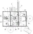
The embodiment, referring to fig. 1 to 9, discloses a coaxial double-ended automatic terminal crimping machine, which includes a fixed frame 1, two processing devices 2 with the same structure are arranged on the fixed frame 1, a wire harness circular cutting and feeding mechanism 3, a wire harness reversing mechanism 4 and a finished product taking-out mechanism 5 are further arranged on the fixed frame 1, the two processing devices 2 are arranged side by side, the wire harness circular cutting and feeding mechanism 3 is arranged corresponding to the processing device 2 on the left side, the wire harness reversing mechanism 4 is arranged between the two processing devices 2, and the finished product taking-out mechanism 5 is arranged corresponding to the processing device 2 on the right side.
The processing device 2 comprises a multi-station indexing and rotating mechanism 21 which is rotatably arranged on the fixed rack 1, and a wire harness peeling mechanism 22 and a wire harness terminal punching mechanism 23 are sequentially arranged on the fixed rack 1 corresponding to the multi-station indexing and rotating mechanism 21 according to a processing sequence.
The processing device 2 further comprises a terminal testing mechanism 23, and the terminal testing mechanism 23 is arranged on the rear side of the wire harness terminal printing mechanism 23 corresponding to the station indexing and rotating mechanism 21.
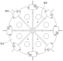
The multi-station indexing rotary mechanism 21 includes a rotary indexing disc 211, a plurality of wire clamping mechanisms 212 are circularly arranged on the rotary indexing disc 211 at intervals, and a wire harness guide tube 213 for guiding a wire harness is provided on the selective indexing disc corresponding to the wire clamping mechanisms 212. In the present embodiment, the number of the thread tension mechanisms 212 is eight.
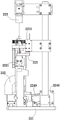
The wire harness peeling mechanism 22 comprises a peeling bottom plate 221, a first linear guide rail is arranged on the peeling bottom plate 221, a peeling V-shaped knife assembly is arranged on the first linear guide rail in a back-and-forth moving mode, a wire harness positioning device 222 and a CCD visual detection system 223 for detecting the peeling position and the wire harness length of the wire harness to be processed are arranged above the peeling V-shaped knife assembly corresponding to the peeling V-shaped knife assembly.
The V sword subassembly of skinning is including opening and shutting support 2241, V sword motor 2242 that opens and shuts, just reversing screw thread lead screw 2243, go up skinning knife 2244 and skinning knife 2245 down, should open and shut support 2241 and movably set up on this first linear guide, be equipped with on this skinning bottom plate 221 and order about the pivoted drive belt by V sword back-and-forth movement motor 2246, should open and shut support 2241 and drive belt 2249 fixed connection, just reversing screw thread lead screw 2243 rotationally sets up on this opening and shutting support 2241, this just reversing screw thread lead screw 2243 vertically sets up, be equipped with positive screw on this just reversing screw thread lead screw 2243, reverse screw thread, respectively the cover be equipped with on positive screw thread, reverse screw thread and move the seat 2247, move down the seat 2248, go up skinning knife 2244, skinning knife 2245 down is fixed in this and moves the seat 2247 respectively, moves the seat 2248 front end down, this goes up skinning knife 2244, skinning knife 2245 is corresponding to set up, this just reversing screw thread lead screw 2243 is connected through drive mechanism with V sword 2242 and opens and shuts.
The wire harness positioning device 222 comprises a wire harness positioning guide 2221 and a wire harness positioning cylinder 2222, wherein the wire harness positioning cylinder 2222 is axially arranged above the upper peeling knife 2244 in the downward direction, the wire harness positioning guide 2221 is arranged in front of the upper peeling knife 2244, and the wire harness positioning guide 2221 is fixed on a cylinder shaft of the wire harness positioning cylinder 2222.
The wire harness reversing mechanism 4 comprises a reversing vertical plate 41, a reversing seat 42, a wire feeding lifting cylinder 43, a wire feeding motor 44, a wire feeding rubber wheel 45 and a rubber wheel clamping assembly 46, wherein the reversing vertical plate 41 is longitudinally fixed on the fixed frame 1, the reversing seat 42 is arranged on the reversing vertical plate 41 in a left-right movable manner, the wire feeding lifting cylinder 43 is axially arranged on the reversing seat 42, a lifting seat 47 is fixed on a cylinder shaft of the wire feeding lifting cylinder 43, an output shaft of the wire feeding motor 44 is upwardly fixed on the lifting seat 47, the wire feeding rubber wheel 45 is fixed on an output shaft of the wire feeding motor 44, and the rubber wheel clamping assembly 46 is arranged on the lifting seat 47 corresponding to the wire feeding rubber wheel 45.
The rubber wheel clamping assembly 46 comprises a clamping cylinder 461, a clamping wheel 462 and a clamping swing arm 463, wherein the clamping swing arm 463 is hinged on the lifting seat 47, an output shaft of the clamping cylinder 461 is upwards arranged corresponding to the lower end of the clamping swing arm 463, and the clamping wheel 462 is hinged on the upper end of the clamping swing arm 463 corresponding to the feeding rubber wheel.
A second linear guide rail is transversely arranged on the reversing vertical plate 41, the reversing base 42 is arranged on the second linear guide rail in a left-right moving manner, oil pressure buffers 48 are respectively arranged at the left side and the right side of the second linear guide rail corresponding to the reversing base 42, and position sensors 49 are arranged at the left end and the right end of the lower part of the second linear guide rail corresponding to the reversing base 42.
The peeling bottom plate 221 is provided with a waste material discharge pipe 225 corresponding to the peeling V-knife assembly.
When the wire harness girdling feeding mechanism is used, a wire harness is cut to a set length by the wire harness girdling feeding mechanism and is conveyed to the position of the rotary dividing disc 211 positioned on the left side, the rotary dividing disc 211 is driven to rotate by a rotary motor arranged in the fixed rack 1, therefore, a plurality of wire clamping mechanisms 212 sequentially clamp the wire harness, and the rotary motor rotates to bring one wire clamping mechanism 212 to the wire harness peeling mechanism 22.
The wiring harness positioning device 222 positions the wiring harness, the CCD vision detection system 223 detects the length of the wiring harness and the opening stripping position, the upper peeling knife 2244 and the lower peeling knife 2245 are controlled to be folded by the positive and negative rotation threaded screw rod 2243 to cut the wiring harness skin, and the opening and closing support 2241 is driven to move by the V-shaped knife back and forth moving motor 2246, so that the skin is pulled apart.
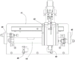
The wire harness terminal crimping mechanism 23 includes a fixed base 231, and further includes a terminal machine forward-backward moving mechanism 232, a terminal machine lifting mechanism 233, a terminal machine 234, a waste discharging mechanism 235, a wire harness positioning mechanism 236 and a CCD vision detecting system 237, the terminal machine forward-backward moving mechanism 232 is fixed on the fixed base 231, an output end of the terminal machine lifting mechanism 233 is upwardly arranged on the terminal machine forward-backward moving mechanism 232, the terminal machine 234 is fixed on an output end of the terminal machine lifting mechanism 233, the waste discharging mechanism 235 is arranged on the terminal machine 234, and the wire harness positioning mechanism 236 and the CCD vision detecting system 237 are movably arranged on the fixed base 231 corresponding to the terminal machine 234.
The terminal machine front-and-back moving mechanism 232 comprises an installation bottom plate 2321, a linear guide 2322, a screw 2323 and a servo motor 2324, wherein the installation bottom plate 2321 is translatably arranged on the fixed base 231 through the linear guide 2322, the screw 2323 is parallel to the linear guide 2322 and is rotatably arranged on the fixed base 231, a rotating sliding seat matched with the screw 2323 is arranged on the lower surface of the installation bottom plate 2321, the servo motor 2324 is fixed at the bottom of the fixed base 231, and a transmission mechanism is arranged between the servo motor 2324 and the screw 2323.
The terminal lifting mechanism 233 includes a linear electric cylinder 2331, the linear electric cylinder 2331 is fixed to the mounting base plate 2321, a fixing plate 2332 is provided at an output end of the linear electric cylinder 2331, the terminal 234 is fixed to the fixing plate 2332, a guide post 2334 is provided on a lower surface of the fixing plate 2332, and an oilless bushing 2335 is provided on the mounting base plate 2321 corresponding to the guide post 2334.
The waste discharging mechanism 235 includes a blanking base 2351, a blanking cylinder 2352, a waste guide 2353, a waste pressing block 2354, a spring 2355, a first cutter 2356 and a second cutter 2357, wherein the blanking base 2351 is fixed on the terminal machine 234, the first cutter 2356 is fixed at the front end of the blanking base 2351, the blanking cylinder 2352 is transversely arranged at the left side of the blanking base 2351, the second cutter 2357 is fixed on the cylinder shaft of the blanking cylinder 2352 corresponding to the first cutter 2356, the waste guide 2353 is arranged at the rear end of the blanking base 2351 corresponding to the first cutter 2356 and the second cutter 2357, the waste pressing block 2354 is arranged below the first cutter 2356 in a left-right moving manner, and the spring 2355 is arranged at the right side of the waste pressing block 2354.
The peeled wire harness is riveted with a terminal at the wire harness terminal crimping mechanism 23, after the terminal performance test is carried out by the terminal testing mechanism 24, the wire harness rotates to the wire harness reversing mechanism 4, the wire feeding rubber wheel 45 and the clamping wheel 462 clamp the wire harness, the reversing seat 42 moves rightwards, when the wire harness moves to a set position, the wire feeding motor 44 stops rotating, so that the wire harness is fed into the rotary dividing disc 211 on the right side, one end of the wire harness, which is riveted with the terminal, extends into the wire harness guide pipe 213, the wire clamping mechanism 212 clamps the wire harness, the wire harness is sequentially processed by the wire harness peeling mechanism 22, the wire harness terminal crimping mechanism 23 and the wire harness testing mechanism, and when the other end of the wire harness is processed, a finished product is taken out by the finished product taking-out mechanism 5.
The automatic terminal soldering machine is reasonable and ingenious in structural design, adopts two indexing rotary disks for butt joint operation, and is multifunctional automatic equipment for realizing terminal soldering of two ends of a wiring harness or terminal soldering of one end of the wiring harness; according to the invention, a CCD vision system is adopted to accurately detect the wire harness and the terminal, so that the position tolerance of the wire harness and the terminal is ensured to be within +/-0.05 mm; the rotary type separated-station production is adopted, the working time of a single station is independent, the production time is shortened, and the production efficiency is improved.
The foregoing is merely a preferred embodiment of the invention and is not intended to limit the invention in any manner. Those skilled in the art can make many possible variations and modifications to the disclosed solution, or modify the equivalent embodiments using the technical means and teachings disclosed above, without departing from the scope of the present solution. Therefore, equivalent changes in shape, structure and principle according to the invention should be covered by the protection scope of the invention without departing from the technical scheme of the invention.
Claims (9)
1. The utility model provides an automatic terminal machine of beating of coaxial line double-end, its characterized in that including fixed frame: the wire harness ring cutting and feeding mechanism is arranged corresponding to the processing device on the left side, the wire harness reversing mechanism is arranged between the two processing devices, the finished product taking-out mechanism is arranged corresponding to the processing device on the right side, the wire harness reversing mechanism comprises a reversing vertical plate, a reversing seat, a wire feeding lifting cylinder, a wire feeding motor, a wire feeding rubber wheel and a rubber wheel clamping assembly, the reversing vertical plate is longitudinally fixed on the fixed frame, the reversing seat is arranged on the reversing vertical plate in a manner of being capable of moving left and right, the wire feeding lifting cylinder is arranged on the reversing seat axially, a lifting seat is fixed on a cylinder shaft of the wire feeding lifting cylinder, an output shaft of the wire feeding motor is fixed on the lifting seat upwardly, the wire feeding rubber wheel is fixed on an output shaft of the wire feeding motor, and the rubber wheel clamping assembly is arranged on the lifting seat correspondingly to the wire feeding rubber wheel.
2. The coaxial line double-end automatic terminal crimping machine according to claim 1, wherein the processing device comprises a multi-station indexing rotation mechanism rotatably disposed on the fixed frame, and a wire harness peeling mechanism and a wire harness terminal crimping mechanism are sequentially disposed on the fixed frame corresponding to the multi-station indexing rotation mechanism in a processing sequence.
3. The coaxial double-ended automatic terminal crimping machine according to claim 2, wherein the processing device further comprises a terminal testing mechanism, and the terminal testing mechanism is arranged on the rear side of the wiring harness terminal crimping mechanism corresponding to the station indexing and rotating mechanism.
4. The coaxial line double-end automatic terminal crimping machine according to claim 2 or 3, wherein the multi-station indexing rotating mechanism comprises a rotating indexing disc, a plurality of wire clamping mechanisms are arranged on the rotating indexing disc in a circular manner at intervals, and a wire harness guide pipe for guiding a wire harness is arranged on the rotating indexing disc corresponding to the wire clamping mechanisms.
5. The coaxial double-ended automatic terminal crimping machine according to claim 2 or 3, wherein the wire harness stripping mechanism comprises a stripping bottom plate, a first linear guide rail is arranged on the stripping bottom plate, a stripping V-shaped knife assembly is arranged on the first linear guide rail in a manner of moving back and forth, a wire harness positioning device and a CCD visual detection system for detecting the stripping position and the length of a wire harness to be processed are arranged above the stripping V-shaped knife assembly and correspond to the stripping V-shaped knife assembly.
6. The coaxial double-ended automatic terminal crimping machine according to claim 5, wherein the peeling V-knife assembly comprises an open-close bracket, a V-knife open-close motor, a forward and reverse threaded lead screw, an upper peeling knife and a lower peeling knife, the open-close bracket is movably disposed on the first linear guide rail, a transmission belt driven to rotate by the V-knife forward and backward movement motor is disposed on the peeling bottom plate, the open-close bracket is fixedly connected with the transmission belt, the forward and reverse threaded lead screw is rotatably disposed on the open-close bracket, the forward and reverse threaded lead screw is longitudinally disposed, the forward and reverse threaded lead screw is provided with a forward thread and a reverse thread, the forward and reverse threads are respectively sleeved with an upper moving seat and a lower moving seat, the upper peeling knife and the lower peeling knife are respectively fixed at front ends of the upper moving seat and the lower moving seat, the upper peeling knife and the lower peeling knife are correspondingly disposed, and the forward and reverse threaded lead screw and the V-knife motor pass through the open-close machine via the belt
The structure is connected.
7. The coaxial double-ended automatic terminal crimping machine as claimed in claim 6, wherein the harness positioning device comprises a harness positioning guide, a harness positioning cylinder, the harness positioning cylinder being disposed axially downwardly above the upper skinning knife, the harness positioning guide being disposed forwardly of the upper skinning knife.
8. The coaxial double-ended automatic terminal crimping machine according to claim 1, wherein the rubber wheel clamping assembly comprises a clamping cylinder, a clamping wheel and a clamping swing arm, the clamping swing arm is hinged on the lifting seat, an output shaft of the clamping cylinder is upwards arranged corresponding to the lower end of the clamping swing arm, and the clamping wheel is hinged on the upper end of the clamping swing arm corresponding to the wire feeding rubber wheel;
the reversing vertical plate is transversely provided with a second linear guide rail, the reversing seat is arranged on the second linear guide rail in a manner of moving left and right, the left side and the right side of the second linear guide rail are respectively provided with an oil buffer corresponding to the reversing seat, and the left end and the right end of the lower part of the second linear guide rail are provided with position sensors corresponding to the reversing seat.
9. The coaxial double-end automatic terminal crimping machine according to claim 2 or 3, wherein the harness terminal crimping mechanism comprises a fixed base, a front-back moving mechanism of the terminal machine, a lifting mechanism of the terminal machine, a waste discharging mechanism, a harness positioning mechanism and a CCD visual detection system, the front-back moving mechanism of the terminal machine is fixed on the fixed base, the fixed base is arranged on a fixed frame, the output end of the lifting mechanism of the terminal machine is upwards arranged on the front-back moving mechanism of the terminal machine, the terminal machine is fixed on the output end of the lifting mechanism of the terminal machine, the waste discharging mechanism is arranged on the terminal machine, and the harness positioning mechanism and the CCD visual detection system are movably arranged on the fixed base corresponding to the terminal machine.
Priority Applications (1)
| Application Number | Priority Date | Filing Date | Title |
|---|---|---|---|
| CN201710381755.4A CN106981808B (en) | 2017-05-26 | 2017-05-26 | Coaxial line double-end automatic terminal crimping machine |
Applications Claiming Priority (1)
| Application Number | Priority Date | Filing Date | Title |
|---|---|---|---|
| CN201710381755.4A CN106981808B (en) | 2017-05-26 | 2017-05-26 | Coaxial line double-end automatic terminal crimping machine |
Publications (2)
| Publication Number | Publication Date |
|---|---|
| CN106981808A CN106981808A (en) | 2017-07-25 |
| CN106981808B true CN106981808B (en) | 2023-01-20 |
Family
ID=59344328
Family Applications (1)
| Application Number | Title | Priority Date | Filing Date |
|---|---|---|---|
| CN201710381755.4A Active CN106981808B (en) | 2017-05-26 | 2017-05-26 | Coaxial line double-end automatic terminal crimping machine |
Country Status (1)
| Country | Link |
|---|---|
| CN (1) | CN106981808B (en) |
Families Citing this family (7)
| Publication number | Priority date | Publication date | Assignee | Title |
|---|---|---|---|---|
| CN107465064B (en) * | 2017-08-18 | 2024-03-22 | 厦门海普锐科技股份有限公司 | Terminal threading device |
| CN107834334B (en) * | 2017-10-29 | 2019-11-08 | 江苏华鹏智能仪表科技股份有限公司 | A kind of portion terminal pressing method based on full-automatic pressure terminal device |
| CN107681408B (en) * | 2017-11-01 | 2024-02-13 | 苏州正兆机械有限公司 | Double-end full-automatic terminal machine for wire harness |
| CN107809096B (en) * | 2017-11-29 | 2023-09-15 | 昆山雷匠通信科技有限公司 | Double-end coaxial line's processor |
| CN107803450B (en) * | 2017-11-29 | 2023-09-15 | 昆山雷匠通信科技有限公司 | Wire feeding device |
| CN108847619A (en) * | 2018-06-20 | 2018-11-20 | 国网江苏省电力有限公司泰州供电分公司 | A kind of cable stripping device |
| CN112951594B (en) * | 2020-12-31 | 2024-08-27 | 苏州美仪自动化设备有限公司 | Automatic sleeve pipe of coil makes terminal machine |
Citations (5)
| Publication number | Priority date | Publication date | Assignee | Title |
|---|---|---|---|---|
| CN102354892A (en) * | 2011-08-31 | 2012-02-15 | 东莞市胜蓝电子有限公司 | Automatic control system for double-head terminal crimping machine |
| CN102709782A (en) * | 2012-06-21 | 2012-10-03 | 林应听 | Multifunctional full automatic wire ranging terminal pressing machine |
| CN103746259A (en) * | 2014-01-18 | 2014-04-23 | 徐中 | Full automatic double-line plying terminal crimping machine |
| CN204809615U (en) * | 2015-08-03 | 2015-11-25 | 深圳市林全科技有限公司 | Full -automatic crimping machine |
| CN207474894U (en) * | 2017-05-26 | 2018-06-08 | 东莞市典桢机械有限公司 | The automatic terminal machine of coaxial line double end |
Family Cites Families (1)
| Publication number | Priority date | Publication date | Assignee | Title |
|---|---|---|---|---|
| DE50305314D1 (en) * | 2002-02-22 | 2006-11-23 | Komax Holding Ag | Crimping press for producing a crimp connection |
-
2017
- 2017-05-26 CN CN201710381755.4A patent/CN106981808B/en active Active
Patent Citations (5)
| Publication number | Priority date | Publication date | Assignee | Title |
|---|---|---|---|---|
| CN102354892A (en) * | 2011-08-31 | 2012-02-15 | 东莞市胜蓝电子有限公司 | Automatic control system for double-head terminal crimping machine |
| CN102709782A (en) * | 2012-06-21 | 2012-10-03 | 林应听 | Multifunctional full automatic wire ranging terminal pressing machine |
| CN103746259A (en) * | 2014-01-18 | 2014-04-23 | 徐中 | Full automatic double-line plying terminal crimping machine |
| CN204809615U (en) * | 2015-08-03 | 2015-11-25 | 深圳市林全科技有限公司 | Full -automatic crimping machine |
| CN207474894U (en) * | 2017-05-26 | 2018-06-08 | 东莞市典桢机械有限公司 | The automatic terminal machine of coaxial line double end |
Also Published As
| Publication number | Publication date |
|---|---|
| CN106981808A (en) | 2017-07-25 |
Similar Documents
| Publication | Publication Date | Title |
|---|---|---|
| CN106981808B (en) | Coaxial line double-end automatic terminal crimping machine | |
| CN103151736B (en) | Multi-functional full-automatic quick cable-stripping machine | |
| CN107838792B (en) | A kind of bamboo slicer | |
| CN209844174U (en) | Automatic wiring harness assembling machine with double-head beating end and inserting shell | |
| CN203734118U (en) | Full-automatic wire cutting, stripping and dipping machine | |
| CN103022854B (en) | A kind of automatic tangent peeling loose end press | |
| CN204424667U (en) | Full-automatic cable terminal press | |
| CN108355984B (en) | Motor stator detects depiler based on CCD detects | |
| CN209844177U (en) | Full-automatic multi-core wire single-end terminal crimping machine | |
| CN207474894U (en) | The automatic terminal machine of coaxial line double end | |
| CN107706835B (en) | A kind of cable laser cutting peeling equipment | |
| CN203056353U (en) | Automatic-cutting and stripping dispersed-end crimping machine | |
| CN203398503U (en) | Automatic double-end stamping machine for photovoltaic wire | |
| CN110289159B (en) | Automatic wire pulling machine for transformer | |
| CN219610114U (en) | Device is used in processing of new energy automobile pencil | |
| CN208100778U (en) | A kind of pearl automatic punch | |
| CN112170964A (en) | Tubular feedthrough capacitor fixed-length cutting device with surface scratch detection function | |
| CN208117204U (en) | A kind of driver plate potentiometer automatic assembling | |
| CN111037256B (en) | Three-in-one equipment for assembling and testing sun shield | |
| CN109904702B (en) | Full-automatic copper belt machine and operation method thereof | |
| CN206506232U (en) | A kind of Multifunctional wire stripper | |
| CN212682692U (en) | Tubular feedthrough capacitor fixed-length cutting device with surface scratch detection function | |
| CN213079194U (en) | Capacitor braid detection device | |
| CN211679779U (en) | Pencil cutting equipment | |
| CN210090228U (en) | Automatic change grinding wheel performance check out test set |
Legal Events
| Date | Code | Title | Description |
|---|---|---|---|
| PB01 | Publication | ||
| PB01 | Publication | ||
| SE01 | Entry into force of request for substantive examination | ||
| SE01 | Entry into force of request for substantive examination | ||
| GR01 | Patent grant | ||
| GR01 | Patent grant |