CN1069233A - Compound vehicle wheel unit - Google Patents
Compound vehicle wheel unit Download PDFInfo
- Publication number
- CN1069233A CN1069233A CN92109283A CN92109283A CN1069233A CN 1069233 A CN1069233 A CN 1069233A CN 92109283 A CN92109283 A CN 92109283A CN 92109283 A CN92109283 A CN 92109283A CN 1069233 A CN1069233 A CN 1069233A
- Authority
- CN
- China
- Prior art keywords
- accessory whorl
- vehicle wheel
- wheel
- compound vehicle
- wheel unit
- Prior art date
- Legal status (The legal status is an assumption and is not a legal conclusion. Google has not performed a legal analysis and makes no representation as to the accuracy of the status listed.)
- Granted
Links
Images


Classifications
-
- B—PERFORMING OPERATIONS; TRANSPORTING
- B60—VEHICLES IN GENERAL
- B60B—VEHICLE WHEELS; CASTORS; AXLES FOR WHEELS OR CASTORS; INCREASING WHEEL ADHESION
- B60B11/00—Units comprising multiple wheels arranged side by side; Wheels having more than one rim or capable of carrying more than one tyre
- B60B11/04—Wheels with a rim capable of carrying more than one tyre
-
- B—PERFORMING OPERATIONS; TRANSPORTING
- B60—VEHICLES IN GENERAL
- B60B—VEHICLE WHEELS; CASTORS; AXLES FOR WHEELS OR CASTORS; INCREASING WHEEL ADHESION
- B60B19/00—Wheels not otherwise provided for or having characteristics specified in one of the subgroups of this group
- B60B19/003—Multidirectional wheels
-
- B—PERFORMING OPERATIONS; TRANSPORTING
- B60—VEHICLES IN GENERAL
- B60C—VEHICLE TYRES; TYRE INFLATION; TYRE CHANGING; CONNECTING VALVES TO INFLATABLE ELASTIC BODIES IN GENERAL; DEVICES OR ARRANGEMENTS RELATED TO TYRES
- B60C7/00—Non-inflatable or solid tyres
-
- B—PERFORMING OPERATIONS; TRANSPORTING
- B60—VEHICLES IN GENERAL
- B60C—VEHICLE TYRES; TYRE INFLATION; TYRE CHANGING; CONNECTING VALVES TO INFLATABLE ELASTIC BODIES IN GENERAL; DEVICES OR ARRANGEMENTS RELATED TO TYRES
- B60C7/00—Non-inflatable or solid tyres
- B60C7/08—Non-inflatable or solid tyres built-up from a plurality of arcuate parts
-
- B—PERFORMING OPERATIONS; TRANSPORTING
- B60—VEHICLES IN GENERAL
- B60C—VEHICLE TYRES; TYRE INFLATION; TYRE CHANGING; CONNECTING VALVES TO INFLATABLE ELASTIC BODIES IN GENERAL; DEVICES OR ARRANGEMENTS RELATED TO TYRES
- B60C7/00—Non-inflatable or solid tyres
- B60C7/10—Non-inflatable or solid tyres characterised by means for increasing resiliency
- B60C7/102—Tyres built-up with separate rubber parts
-
- B—PERFORMING OPERATIONS; TRANSPORTING
- B60—VEHICLES IN GENERAL
- B60B—VEHICLE WHEELS; CASTORS; AXLES FOR WHEELS OR CASTORS; INCREASING WHEEL ADHESION
- B60B2310/00—Manufacturing methods
- B60B2310/20—Shaping
- B60B2310/226—Shaping by cutting
-
- B—PERFORMING OPERATIONS; TRANSPORTING
- B60—VEHICLES IN GENERAL
- B60B—VEHICLE WHEELS; CASTORS; AXLES FOR WHEELS OR CASTORS; INCREASING WHEEL ADHESION
- B60B2360/00—Materials; Physical forms thereof
- B60B2360/50—Rubbers
-
- B—PERFORMING OPERATIONS; TRANSPORTING
- B60—VEHICLES IN GENERAL
- B60B—VEHICLE WHEELS; CASTORS; AXLES FOR WHEELS OR CASTORS; INCREASING WHEEL ADHESION
- B60B2380/00—Bearings
- B60B2380/10—Type
- B60B2380/12—Ball bearings
-
- B—PERFORMING OPERATIONS; TRANSPORTING
- B60—VEHICLES IN GENERAL
- B60B—VEHICLE WHEELS; CASTORS; AXLES FOR WHEELS OR CASTORS; INCREASING WHEEL ADHESION
- B60B2380/00—Bearings
- B60B2380/10—Type
- B60B2380/14—Roller bearings
-
- B—PERFORMING OPERATIONS; TRANSPORTING
- B60—VEHICLES IN GENERAL
- B60B—VEHICLE WHEELS; CASTORS; AXLES FOR WHEELS OR CASTORS; INCREASING WHEEL ADHESION
- B60B2380/00—Bearings
- B60B2380/10—Type
- B60B2380/18—Plain or sleeve bearings
-
- B—PERFORMING OPERATIONS; TRANSPORTING
- B60—VEHICLES IN GENERAL
- B60B—VEHICLE WHEELS; CASTORS; AXLES FOR WHEELS OR CASTORS; INCREASING WHEEL ADHESION
- B60B2900/00—Purpose of invention
- B60B2900/10—Reduction of
- B60B2900/131—Vibrations
Abstract
A kind of compound vehicle wheel unit, by being that a collection of accessory whorl (31) that rotatable support is made at the center is disposed on this wheel rim and constitutes tire with wheel circular rim (12) tangential direction axle in the same way, make the rotation of the rotation of tire and accessory whorl combined, so that wheel travel according to any direction.
Description
The present invention relates to the rotatable wheel that travels, more particularly, relate to two compound vehicle wheel units that rotate travel direction with phase quadrature.
Along ground or the wheel that travels such as table top generally comprise: constitute the wheel outer peripheral portion and tire, the wheel rim that supports this tire made by rubber or metal etc., be installed on the wheel hub on the axletree, and the wheel bearing arrangement of forming by the spoke that connects wheel rim and wheel hub etc.
This kind wheel is owing to be to be that rotate at the center with the wheel shaft, and its travel direction is limited to the direction with the wheel shaft quadrature.For this reason, when need changes wheel travel direction, generally be to utilize the control that links to each other with wheel shaft to device, wheel shaft itself is turned to position with the travel direction quadrature.
Above-mentioned this make wheel shaft together with whole wheel to the method for travel direction, because tire has very big contact friction force with ground (table top), the just very difficult rotation of wheel when stopping.Exist in addition with next class problem: have to cross when turning to predetermined travel direction difficultly and do not wish the arc track that occurs, line direction is sailed in then extremely difficult change in narrow space.
In order to address the above problem, adopted a kind of steering yoke bolt trim attachment, make the axle that is located at wheel shaft quadrature and eccentric position place rotate the whole wheel of meeting.But this wheel caster device also fails to overcome the above problems fully, still exists to be difficult to change travel direction when stopping and to be difficult for towards orthogonal directions problem such as change direction.Remove this,, then have the moving velocity must not be too fast and wheel diameter is not too much waits restriction during use because the direction of wheel shaft changes easily in advancing.
A kind of solution in addition is to have developed a kind of like this wheel assembly, and it is with two wheel shaft quadratures but the result that separate wheel is made up.But in this kind wheel assembly, when having used one of them wheel, just must not employ another, thereby just must design special wheel mobile traction device, shortcomings such as complex structure and device maximization appear in the result.
The present invention's purpose is to address the above problem, and makes wheel can not retouch out the circular arc track and can change travel direction simply.Can realize simply to change the wheel assembly of travel direction simultaneously with simple and small-scale structure.
In order to achieve the above object, the invention is characterized in that the equidirectional axle of handle and wheel circular rim tangential direction is assemblied on this wheel rim for centre bearing becomes rotatable a collection of accessory whorl, constitutes tire thus.
In compound vehicle wheel unit of the present invention, have on its periphery form by the wheel supporting mechanism that circular rim is arranged, at a plurality of accessory whorl supporting devices of this wheel rim upper edge radial outward setting and be respectively that above-mentioned accessory whorl supporting device supported can around with the equidirectional axle of the tangential direction of above-mentioned wheel rim be a plurality of accessory whorls that rotate at the center, in addition, form tire by the above-mentioned a plurality of accessory whorls that are installed on the circumference.
According to compound vehicle wheel unit of the present invention, tire can be when rotational axis direction advances along wheel, by the rotation of accessory whorl can along with the rotation direction of the wheel shaft direction running of quadrature mutually.When combined, then can make wheel shaft not go to travel direction and allow wheel travel according to any direction the rotation of the rotation of tire and accessory whorl.
As mentioned above, according to the present invention, the travel direction that arbitrarily and easily changes wheel under the circular arc tracking condition can not retouched out.Simultaneously, always do not carry out certain required when mobile wheel combination form to device and according to walking because control that wheel shaft uses is set, thus can make the mounting structure of wheel simply and not can make about the structure complicated and the maximization of vehicle etc.
Compound vehicle wheel unit of the present invention, can identically with the wheel that has earlier use as the single structure body, if it is used as the wheel that needs the vehicle of change travel direction in narrow ground, is engaged in and is necessary not retouch arc track and changes running wheel required in wheel that the robot of certain operation of direct of travel uses or amusement that requires the special operational performance or the athletic equipment etc., when meeting obtains superior especially effect.
Brief description accompanying drawing of the present invention.
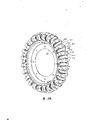
Fig. 1 is oblique diagrammatic sketch, shows the outward appearance of the present invention's compound vehicle wheel unit one embodiment; Fig. 2 is discoid pieces and is installed on accessory whorl back plate on this discoid pieces and the stravismus section-drawing of accessory whorl; Fig. 3 shows the bright exploded perspective view that accessory whorl is installed on the method on the accessory whorl back plate; Fig. 4 A is the oblique drawing that shows bright accessory whorl back plate one embodiment, and Fig. 4 B is its birds-eye view (b); Fig. 5 shows that bright a collection of accessory whorl back plate is installed in the outward appearance oblique drawing of the state in the discoid pieces; Fig. 6 shows the oblique drawing of seeing outside the bright second embodiment of the invention; Fig. 7 is the outward appearance oblique drawing that shows compound vehicle wheel unit assemble method among bright second embodiment; Fig. 8 is the exploded perspective view that shows the accessory whorl supporting structure among bright second embodiment; Fig. 9 is the oblique drawing that shows accessory whorl support unit outward appearance among bright second embodiment; Figure 10 shows the oblique drawing of seeing outside one of bright second embodiment of the invention change form example; Figure 11 shows the oblique drawing of seeing outside the bright third embodiment of the invention; Figure 12 shows the bright outward appearance oblique drawing that accessory whorl is assemblied in the state in the accessory whorl support unit among the 3rd embodiment; Figure 13 shows the oblique drawing of seeing outside the guard member of bright junction surface; Figure 14 shows the oblique drawing of seeing outside the accessory whorl supporting structure among bright the 3rd embodiment; Figure 15 is rotation that accessory whorl among the 3rd embodiment schematically is described and the section-drawing of braking function; Figure 16 shows the oblique drawing of seeing outside one of bright the 3rd embodiment change form example; Figure 17 is the outward appearance oblique drawing that shows bright accessory whorl support unit one change form example; Figure 18 shows the oblique drawing of seeing outside the guard member of bright junction surface; Figure 19 shows the oblique drawing of seeing outside one of bright accessory whorl change form example; Figure 20 is for showing the exploded perspective view of bright relevant combined method; Figure 21 shows the oblique drawing of seeing outside bright a whole set of equipment that has assembled; Figure 22 is the part sectional view of showing bright accessory whorl supporting structure; Figure 23 is for showing the front elevation of bright fourth embodiment of the invention, and Figure 24 is its lateral plan; Figure 25 is the section-drawing of the A-A line of Figure 23; Figure 26 shows the oblique drawing of seeing outside the bright fifth embodiment of the invention; Figure 27 is the vertical part surface figure of the compound vehicle wheel unit among Fig. 5 embodiment; Figure 28 shows the oblique drawing of seeing outside the accessory whorl bearing among bright the 5th embodiment.
Embodiments of the invention are described with reference to the accompanying drawings.
Fig. 1 is the oblique drawing that shows bright the present invention's one of compound vehicle wheel unit 10 embodiment outward appearance.
Several numbers 11 dish among the figure for the whole wheel of supporting.The periphery of dish 11 is formed with circular wheel rim 12, and middle body is provided with wheel shaft (not showing bright) patchhole 13.
As shown in Figure 2, circular rim 12 first-class pitches be provided with a collection of equidirectional groove 14 of coil axis of taking turns therewith.The bottom that accessory whorl back plate 21 of intercalation outwardly radially in the groove 14.
Bottom 22 has with groove 14 width T and equates substantially or bigger thickness t.Be provided with the bearing hole that can allow back plate 21 pass through in the accessory whorl bearing portion 23, this bearing hole is made up of two bearing hole 25a and 25b, their axis 24a and 24b respectively with the line of accessory whorl back plate 21 quadratures at angle θ 22 tilt towards the bottom.In accessory whorl bearing portion 23, for the bearing length that makes two bearing hole 25a, 25b increases, be provided with the lug boss 26 of two inclination forms, their inclined-plane 26a is with respect to accessory whorl back plate 21,22 reduces gradually to tilt with angle θ towards the bottom respectively.This angle θ is by the number that is set in groove 14 on the wheel rim 12, that is is by the accessory whorl number decision of being supported for accessory whorl back plate 21.
The accessory whorl back plate of being made up of said structure 21 is as Fig. 2 and shown in Figure 5, is by bottom 22 being intercalated in the flute 14 of wheel rim 12, etc. pitch be fixedly installed in the periphery of wheel rim 12.
For shown in Figure 3, be when being attached to accessory whorl back plate 21 on the wheel rim 12, from the both sides of accessory whorl back plate 21 accessory whorl 31 is installed with respect to accessory whorl bearing portion 23.
After the diameter of accessory whorl 31 need make it be installed in accessory whorl back plate 21, make its radially outwardly end can emergence outside wheel back plate 21 outermost end portion.
Accessory whorl 31 is by inserting bearing hole 25a, the 25b of accessory whorl bearing portion 23 with its swivel bearing axle 32, and the energy at both ends is subjected to the supporting of accessory whorl back plate 21.For making accessory whorl 31 can be that the center is done freely to rotate with swivel bearing axle 32, and hole 25a, 25b and axle 32 are all got bearing arrangement.This kind bearing arrangement is according to acting on the load of accessory whorl 31 and the revolution of accessory whorl 31, bearing arrangements such as desirable slip or roller.
By a collection of accessory whorl 31 is made rotatably support with accessory whorl back plate 21 respectively, and be arranged on the periphery of wheel rim 12 with waiting pitch as shown in Figure 1, just constituted most peripheral part (the tire part) 40 of wheel 10 thus.
Compound vehicle wheel unit 10 according to the embodiment of said structure composition has following effect.
Compound vehicle wheel unit 10 can utilize the hole 13 in the dish 11 that wheel shaft is installed and dispose a collection of accessory whorl 31 on circumference and be used as wheel to constitute tire 40.In other words, can wheel shaft (not showing bright) for the center rotates, identical with general wheel, travel by the equidirectional of the rolling movement of tire 40.
If the rolling movement of tire 40 and rotatablely moving of accessory whorl 31 are carried out simultaneously, then compound vehicle wheel unit 10 is by the composite vector direction running of these two motions.Thereby rotatablely moving of rolling movement by controlling tire 40 simultaneously and accessory whorl 31 just can make compound vehicle wheel unit move to any direction under the condition of not turning round wheel shaft.
Fig. 6 to Fig. 9 shows the bright second embodiment of the present invention.
In the present embodiment, comparing among the accessory whorl support unit 42 of swivel bearing accessory whorl 41 and the last embodiment maximized, and intensity also increases.
Accessory whorl support unit 42 has a nicked tilting disk-like member 43 as shown in Figure 9, and it is to become the bottom of inclination disk-like member of two dip plane 43a of platform shape having section, is excised by the section 43b place parallel with the base to form.On the peripheral part of the inclination disk-like member 43 of this otch, be provided with more its outwards outstanding 43c of outer peripheral edges portion of more above-mentioned two dip plane 43a.
These two dip plane 43a respectively with respect to section 43b plane orthogonal, tilt towards mutually approaching direction according to angle θ, and main shaft 44 and countershaft 45 with its quadrature be set respectively on these two dip plane 43a.That is to say that main shaft 44 and the 44a of axis separately of countershaft 45, the line that 45a parallels with respect to section 43b tilt according to angle θ.Remove this, be provided with the hole 44b of the chimeric countershaft 45 of energy in main shaft 44 middle bodies.
On the section 43b opposite end of the inclination disk-like member 43 of otch, be provided with and section 43b parallel T-shaped section rail guide piece 46 substantially.
As shown in Figure 8, in rotating mode diameter being installed on the main shaft 44 of accessory whorl support unit 42 is little hollow cylindrical accessory whorl 41 than disk-like member 43 diameters.In the fitting portion of main shaft 44 and accessory whorl 41, be provided with (not shown)s such as roller bearing component or plain bearing element.
The accessory whorl support unit 42 that is equiped with accessory whorl 41 as shown in Figure 7, be with respect on circular rim 47 peripheries with equidirectional a collection of groove 48 of formation equally spacedly of axis, install by intercalation rail guide piece 46.
In the time of on the periphery that accessory whorl support unit 42 is installed on mutually continuously circular rim 47, the countershaft 45 of adjacent accessory whorl support unit 42 promptly is embedded among the medium pore 44b of main shaft 44, and main shaft 44 is promptly got the structure of two supports axle.
Then Wheel Cover 49 is installed on the wheel rim 47, obtained compound vehicle wheel unit shown in Figure 6 50, it is when the main shaft bigger with diameter 44 rotatably supports accessory whorl 41, because this main shaft 44 can remain in chimerism by the countershaft 45 of the accessory whorl support unit 42 of being located at its free end side vicinity, thereby can increase the load that accessory whorl 41 can bear.
More it is towards radially going out to give prominence to because the part of accessory whorl 41 is configured to section 43b than accessory whorl support unit 42, and this just makes that compound vehicle wheel unit can be identical with the situation in the previous embodiment, can move along the direction identical with wheel shaft.In addition, because the most peripheral of compound vehicle wheel unit 50 part (tire part) forms by the accessory whorl 41 of pitch configuration such as a collection of, just can be identical with common wheel, get the direction identical and advance with the tire rolling sense of motion.
The compound vehicle wheel unit 50 of present embodiment can be used as the wheel assembly that bears big loading, also since outside the inclination disk-like member 43 of otch the footpath big than the diameter of accessory whorl 14, thereby can prevent from the obstacle of compound vehicle wheel unit 50 sides accessory whorl 41 collisions.
Figure 10 is the oblique drawing of seeing outside the change form example one of embodiment illustrated in fig. 6.In the compound vehicle wheel unit 60 of this embodiment, give the section 53a of accessory whorl 41 with the otch disk-like member of the accessory whorl support unit 51 of swivel bearing, its two ends 53b gets smooth circular shape.
Identical among structure and aforementioned second embodiment about it, explanation is omitted.
Like this, because the two ends of the section 53a of accessory whorl support unit 51 are in the arc-shaped, and the peripheral shape of compound vehicle wheel unit 60 is level and smooth, in the time of just wheel being moved axially at compound vehicle wheel unit 60 rolling movements and because of the rotation of accessory whorl 41, a part that reduces accessory whorl parts 51 is to ground-surface impact.The compound vehicle wheel unit of present embodiment is specially adapted to make the occasion of the tilting of wheels.
Figure 11 to Figure 15 shows the bright third embodiment of the present invention.
The elastomeric element of rubber and so on is installed on the two ends of accessory whorl support unit section in the present embodiment.Figure 12 is an accessory whorl support unit 71 used in the present embodiment, it comprises the part of disk-like member is cut off the otch disk-like member 72 of back gained by the section 72a parallel with diametric(al), and along the wheel rim 73 that forms on these otch disk-like member 72 peripheries.One of relative with the section 72a end of wheel rim 73 is provided with and the axis of otch disk-like member 72 rail guide piece 76 that parallel, T-shaped section.On the two ends of this wheel rim 73, the arris Rubber Parts 74 with the dip plane 74a that enlarges to be installed outwardly from the outstanding mode of section 72a.And on the two sides of otch disk-like member 72, then be respectively equipped with outstanding accessory whorl bolster 75, this 75 again respectively at its central authorities be provided with the band linear portion hole 75a.75 of accessory whorl bolsters are arranged to and otch disk-like member 72 quadrature mutually.
77 of hollow cylindrical accessory whorls are respectively with respect to accessory whorl supporting axis 75, and are thereon chimeric in rotating mode from the both sides of otch disk-like member 72.Be embedded in the accessory whorl 77 on its accessory whorl bolster 75 respectively, as shown in figure 14, respectively be provided with joint protective spare 78.This kind joint protective spare 78 is formed by the clap board 78a that forms by inclination angle [theta] with this plate two sides orthogonal and the outstanding two minor axis 78b that are provided with as shown in figure 13, and this minor axis profile that 78b gets can be embedded among the medium pore 75a of accessory whorl bolster 75.
Joint protective spare 78 will make its thick side install towards the direction of the section 72a of otch disk-like member 72, combines to make in abutting connection with the accessory whorl bolster 75 of accessory whorl support unit 71 to make the state that joins continuously via the minor axis 78b of joint protective spare 78.
Give accessory whorl 77 identical with previous embodiment, rail guide piece 76 is intercalated in along in a collection of groove 48 of pitches such as week outside the circular rim 47 formation, constitute compound vehicle wheel unit 70 shown in Figure 11 with 71 of the accessory whorl support units of pivoting support.
The compound vehicle wheel unit 70 of present embodiment is when tilting to the angle that surpasses regulation, and arris Rubber Parts 74 just can contact with ground (or table top).Brake action is played in rotation to accessory whorl 77.That is as shown in figure 15, compound vehicle wheel unit 70 can tilt in angle [alpha], in case the position of ground (or table top) z arrives the position of X, arris Rubber Parts 74 just begins to contact with ground (table top) X.
Further tilt and during position, ground (or table top) changed to the Y position from Z, elastic deformation took place arris Rubber Parts 74 just one side at compound vehicle wheel unit 70, one side increases the brake action that accessory whorl 77 is rotated.
When compound vehicle wheel unit 70 continues to tilt and the position of ground (or table top) when crossing the Y position, the elastic deformation of arris Rubber Parts 74 reaches capacity, and accessory whorl 77 promptly breaks away from ground (or table top) Y.Like this, just make compound vehicle wheel unit 70 stop to shift to because of the mobile direction of the rotation of accessory whorl 77, this direction is with the direct of travel quadrature of compound vehicle wheel unit 70.The direct of travel of device 70 just stops to shift to the direction of quadrature with it.Afterwards, because arris Rubber Parts 74 contacts with ground (or table top) Y, compound vehicle wheel unit 70 is just divided a word with a hyphen at the end of a line towards the main shaft rotation direction.
When physical culture that the compound vehicle wheel unit 70 of present embodiment is used for travelling on the dip plane or apparatus for entertainment, aforementioned this effect will have superior especially effect.For example, the compound vehicle wheel unit 70 of present embodiment is installed on the elongated plate that can accommodate a pin of operator and when constituting running gear, when being ready to a pair of such running gear, allow the operator be through respectively when on the pin walk on the dip plane in the back, just the sensation of putting on general skating boots can be arranged, can carry out traversing action, and the may command speed of travel and direction.
In addition, the compound vehicle wheel unit 70 of present embodiment has adopted 78 pairs of accessory whorl bolsters 75 of joint protective spare to make the structure of two supports, thereby accessory whorl 77 can carry and holds big load.
Figure 16 to Figure 22 is a kind of example that changes form of above-mentioned the 3rd embodiment of the present invention.
In this embodiment, the rubber identical with the 3rd embodiment one class elastic component is installed on the two ends of accessory whorl support unit section.Figure 17 is an accessory whorl support unit 81 used in the present embodiment, it comprise with the part of disk-like member along and the section 82a that radially parallels cut off the otch disk-like member 82 of back gained, and along the formed wheel rim 83 of these otch disk-like member 82 peripheries.On an end relative of wheel rim 83, be equipped with and the axis of otch disk-like member 82 rail guide piece 86 that parallel, that section is T-shaped with section 82a.On the two ends of wheel rim 83, the arris rubber 84 with the dip plane 84a that enlarges and tilt to be installed outwardly from the outstanding mode of section 82a.The two sides of otch disk-like member 82 divide other angle θ towards rail guide piece 86 lopsidedness, and on this evagination ground, two sides the accessory whorl bolster 85 that wherein has hole 85a are being set respectively.Around accessory whorl bolster 85, be provided with jut 87, be used for the gap of labyrinth sealed form sealing cut plectane spare 82 with accessory whorl 88.This accessory whorl bolster 85 and jut 87 respectively with otch disk-like member 82 two sides outstanding setting of mode of quadrature mutually.
Figure 18 shows the joint protective spare 89 that bright and accessory whorl support unit 81 is used in combination, and the shape of the latter and accessory whorl support unit 81 is roughly the same, is provided with than accessory whorl bolster 85 short adapter shaft 85b to replace this accessory whorl bolster 85.Adapter shaft 85b has the shape among the medium pore 85a that can be embedded in accessory whorl bolster 85.As for other parts, its explanation is omitted in identical all indicating with same several numbers among all genus and Figure 17.
The accessory whorl 88 of hollow cylindrical is formed with and is used to carry out labyrinth sealed recess 88b as shown in figure 19.Accessory whorl 88 is embedded on the accessory whorl bolster 85 with rotary way from the two ends of accessory whorl support unit 81 shown in Figure 20 to 22.By jut 87 is inserted among the recess 88b of accessory whorl 88, just can form labyrinth seal.For the chimeric accessory whorl bolster 85 that accessory whorl 88 is arranged, chimeric adapter shaft 85b, erection joint guard member 89 on it thus in its medium pore 85a.The accessory whorl bolster 85 of the accessory whorl support unit 81 of adjacency, then the adapter shaft 85b via joint protective spare 89 forms the state that joins continuously.
Give accessory whorl support unit 81 and the joint protective spare 89 of accessory whorl 88 with swivel bearing; then identical with aforementioned second embodiment; rail guide piece 86 is intercalated in a collection of groove 48 of the first-class pitch of wheel rim 47 peripheries ground formation; then Wheel Cover 49 is installed on the wheel rim 47, constitutes compound vehicle wheel unit 80 shown in Figure 16.
The compound vehicle wheel unit 80 of present embodiment is as the 3rd embodiment, and when tilt quantity surpassed the angle value of regulation, arris Rubber Parts 84 just contacted with ground (or table top), the effect that performance prevents accessory whorl 88 to rotate.Simultaneously, in the present embodiment, combining with the recess 88b of accessory whorl 88 by jut 87 has formed mazy sealing, so just can prevent that foreign matter from invading between accessory whorl bolster 85 and the accessory whorl 88 from the outside.
In addition owing to make joint protective spare 89 and accessory whorl support unit 81 do combination mutually, can make into the width of the accessory whorl 88 of accessory whorl support unit 81 supportings than among the 3rd embodiment greatly.
Figure 23 to Figure 25 shows the clear fourth embodiment of the present invention.A collection of (in the illustrated embodiment being three) accessory whorl 91 is installed in the compound vehicle wheel unit 90 of this embodiment side by side, these three accessory whorls 91 in accessory whorl supporting base 92 according to the outstanding state of a part, be mounted to and can be the longitudinal plane of symmetry rotation around bolster 93, accessory whorl supporting base 92 then waits pitch ground assortment in the periphery of discoideus wheel rim 94.
According to present embodiment, because accessory whorl 91 is by a plurality of side by side configurations together, thereby the width that just can add larger wheels reaches the purpose of the weighing load of increase compound vehicle wheel unit 90.
Figure 26 to 28 shows the bright fifth embodiment of the present invention.Among the compound vehicle wheel unit 100 of this embodiment, be equipped with portion of elastomeric intermediary between its each accessory whorl, the diameter of its formed circumference outmost turns is substantially equal to the circle diameter of the most peripheral that formed by whole accessory whorls of being installed.
In the present embodiment, the lid part of being made by the rubber elastomeric material 103 is installed on the periphery of circular rim 47, on the periphery of lid part 103, along the circumferential direction equally spaced be provided with a collection of perforate part 102, their width allows installing accessory whorl 101, then be provided with Jie portion 105 among a plurality of projection (in examples of Figure 26, totally three projections) 104 radially that has between two perforate parts 102 in placed in the middle and its left and right sides.
This portion of intermediary 105 constitutes, and the circumference that each portion of intermediary projection 104 placed in the middle of assortment along the circumferential direction is connected to form, its diameter roughly equate with the tire circle diameter partly that all accessory whorls 101 by configuration along the circumferential direction form.
As shown in figure 27, accessory whorl bearing 110 is assembled into: on the outer peripheral face of circular rim 47, be filled with elastic caoutchouc parts 116 at middle body, wheel rim attachment face 111 then covers with the portion of intermediary 105 of lid part 103 with hollow cylinder portion 112.When being installed in the wheel rim 47, as shown in figure 28, being preferably in and carrying out after installing accessory whorl 101 as for this accessory whorl bearing 110.
In the compound vehicle wheel unit 100 of present embodiment, because it is on the same circumference basically that the ground plane of the central protrusion 104 of the ground plane of accessory whorl 101 and portion of intermediary 105 is configured in, thereby when directly sailing, accessory whorl 101 and portion of intermediary 105 are that just replace to be contacted with ground.
Like this, the rotation of wheel assembly 100 just can be carried out sleekly and reduce vibration in travelling.In addition, owing to, just can increase the load capacity of wheel assembly 100 acting on load branch on the wheel assembly 100 by accessory whorl 101 and portion of intermediary 105 both burdens.
In addition, even the compound vehicle wheel unit of present embodiment 100 tilts under steam to some extent,, just do not hinder the direction running that this wheel assembly 100 is directly sailed and court and trend are orthogonal because the projection 104 of portion of intermediary 105 can be made elastic deformation with this inclination.
At last, even be that this wheel assembly tilts to have surpassed predetermined angular, because the elastic deformation of the projection 104 of portion of intermediary 105, excessive friction takes place in also unlikely and ground (or table top).
Claims (7)
1, a kind of compound vehicle wheel unit is characterized in that including:
Wheel supporting mechanism is formed with circular wheel rim on its periphery;
A plurality of accessory whorl supporting devices, this mechanism is set on the above-mentioned circular rim along radius direction outwardly;
A plurality of accessory whorls, this accessory whorl are supported on the above-mentioned accessory whorl supporting device, and can be respectively be that rotate at the center with axle with the tangential direction equidirectional of above-mentioned circular rim;
In addition, constitute tire by a plurality of above-mentioned accessory whorl of on circumference, installing.
2, compound vehicle wheel unit as claimed in claim 1 is characterized in that: above-mentioned accessory whorl supporting device forms tabular.
3, compound vehicle wheel unit as claimed in claim 1 is characterized in that: the accessory whorl supporting device has two dip plane that form by predetermined angle incline mutually, and gives prominence to main shaft and the countershaft that is provided with respectively on this dip plane; The countershaft that is formed with countershaft supporting device that can chimeric disposed adjacent at the middle body of above-mentioned main shaft is with perforation, and in rotating mode accessory whorl is installed on the periphery of this main shaft.
4, compound vehicle wheel unit as claimed in claim 3, it is characterized in that: on the dip plane of accessory whorl supporting device, be provided with the annular projection concentric, can be the circular concavity groove that above-mentioned annular projection is inserted and on the side of accessory whorl of supporting that rotates by above-mentioned accessory whorl supporting device, be provided with the center of rotation of accessory whorl.
5, compound vehicle wheel unit as claimed in claim 1; it is characterized in that: the accessory whorl supporting device is by two dip plane that mutually form by predetermined angle incline and outstandingly respectively be arranged on these two dip plane and central authorities are made up of the accessory whorl bolster of perforation; accompany a kind of joint protective spare between two accessory whorl supporting devices that adjoin each other, the section of this joint protective spare is wedge shape and has two minor axises in the central perforation of can be chimeric respectively going into aforementioned accessory whorl bolster.
6, compound vehicle wheel unit as claimed in claim 1, be characterised in that: between the accessory whorl that adjoins each other, along disposing elastomeric intermediary parts on the circumference, and the circle diameter of this intermediary's parts outermost is equated substantially with the most peripheral diameter of the tire of being made of accessory whorl.
7, compound vehicle wheel unit as claimed in claim 1 is characterised in that: accessory whorl is to assemble by a plurality of modes arranged side by side.
Applications Claiming Priority (2)
| Application Number | Priority Date | Filing Date | Title |
|---|---|---|---|
| JP199636/91 | 1991-08-08 | ||
| JP19963691 | 1991-08-08 |
Publications (2)
| Publication Number | Publication Date |
|---|---|
| CN1069233A true CN1069233A (en) | 1993-02-24 |
| CN1041071C CN1041071C (en) | 1998-12-09 |
Family
ID=16411146
Family Applications (1)
| Application Number | Title | Priority Date | Filing Date |
|---|---|---|---|
| CN92109283A Expired - Fee Related CN1041071C (en) | 1991-08-08 | 1992-08-08 | Compound vehicle wheel unit |
Country Status (20)
| Country | Link |
|---|---|
| US (1) | US5383715A (en) |
| EP (1) | EP0556401B1 (en) |
| JP (1) | JP3381848B2 (en) |
| KR (1) | KR930702170A (en) |
| CN (1) | CN1041071C (en) |
| AT (1) | ATE161778T1 (en) |
| AU (1) | AU667050B2 (en) |
| BR (1) | BR9205338A (en) |
| CA (1) | CA2093520A1 (en) |
| DE (1) | DE69223941T2 (en) |
| DK (1) | DK0556401T3 (en) |
| ES (1) | ES2111646T3 (en) |
| FI (1) | FI931563A (en) |
| GE (1) | GEP19981424B (en) |
| NO (1) | NO178488C (en) |
| NZ (1) | NZ243899A (en) |
| RU (1) | RU2090373C1 (en) |
| SG (1) | SG52573A1 (en) |
| TW (1) | TW211546B (en) |
| WO (1) | WO1993002872A1 (en) |
Cited By (9)
| Publication number | Priority date | Publication date | Assignee | Title |
|---|---|---|---|---|
| CN104395101A (en) * | 2012-06-12 | 2015-03-04 | 法国新生活公司 | Omnidirectional wheel |
| CN105246711A (en) * | 2013-05-28 | 2016-01-13 | 戴卡特隆有限公司 | Tire chamber |
| CN106945462A (en) * | 2017-03-15 | 2017-07-14 | 山东蓬翔汽车有限公司 | A kind of lightweight long-life hub assembly |
| CN107933120A (en) * | 2017-12-28 | 2018-04-20 | 内江师范学院 | A kind of unlimited printer of intelligence |
| CN107984967A (en) * | 2017-12-28 | 2018-05-04 | 内江师范学院 | A kind of omni-directional wheel of high accuracy positioning |
| CN109835116A (en) * | 2017-11-27 | 2019-06-04 | 琳赛股份有限公司 | Without gas flexible tire and wheel assembly |
| CN111251781A (en) * | 2018-11-19 | 2020-06-09 | 椅夫健康(厦门)智能科技有限公司 | Welding shaft for universal wheel, wheel assembly of welding shaft and universal wheel |
| CN113443063A (en) * | 2021-07-27 | 2021-09-28 | 哈尔滨轮速科技有限公司 | Electric power-assisted bicycle |
| CN114953849A (en) * | 2022-06-20 | 2022-08-30 | 南京航空航天大学 | Bionic bamboo-joint worm tibia hollow structure spoke type non-inflatable wheel |
Families Citing this family (39)
| Publication number | Priority date | Publication date | Assignee | Title |
|---|---|---|---|---|
| US5553874A (en) * | 1994-09-06 | 1996-09-10 | Schouten; Pieter | Truck assembly for roller board apparatus |
| GB2302866A (en) * | 1995-06-30 | 1997-02-05 | Lanton Park Ltd | Process and Apparatus for Recycling Airborne Particulate Matter |
| US5720529A (en) * | 1996-12-20 | 1998-02-24 | Barron; Bruce J. | Roller skate wheel |
| DE19703285A1 (en) * | 1997-01-30 | 1998-08-06 | Estebanez Eva Garcia | Wheel with elastic tyre |
| AU7204698A (en) | 1997-03-17 | 1998-10-12 | Viktor Schatz | Wheel and belt drive with transversal brake |
| US6250355B1 (en) | 1999-05-19 | 2001-06-26 | Anthony Italo Provitola | Wheel and tire structure |
| US6516848B1 (en) * | 1999-05-18 | 2003-02-11 | Anthony Italo Provitola | Toroidal wheel |
| AU1905001A (en) * | 1999-10-11 | 2001-04-23 | Vladimir Valentinovich Prokhorov | 2-dimensional support and propulsion device and variants thereof, frictional direction stabilizer, t-square and coordinate measurement device |
| US6672931B1 (en) * | 2000-11-14 | 2004-01-06 | Jim Bagley | Interconnectable model construction elements |
| JP2003063202A (en) * | 2001-08-24 | 2003-03-05 | Kyosho Corp | Wheel of traveling body |
| US6948998B2 (en) * | 2003-02-07 | 2005-09-27 | Jim Bagley | Interconnectable model construction elements |
| US7069699B2 (en) * | 2003-02-19 | 2006-07-04 | Anthony Italo Provitola | Toroidal frameworks connection |
| US7311329B2 (en) | 2003-05-23 | 2007-12-25 | Pride Mobility Products Corporation | Anti-tip wheel for a wheelchair |
| US7056185B1 (en) | 2004-10-04 | 2006-06-06 | Thomas Anagnostou | Single axle wireless remote controlled rover with omnidirectional wheels |
| US20080018167A1 (en) * | 2004-12-20 | 2008-01-24 | Shinichiro Fuji | Omnidirectionally Moving Wheel, Moving Device, Carrying Device, and Massage Device |
| US7730978B2 (en) * | 2006-06-30 | 2010-06-08 | Donald Dixon | All-terrain robotic omni-directional drive assembly |
| US8025551B2 (en) * | 2006-09-20 | 2011-09-27 | Mattel, Inc. | Multi-mode three wheeled toy vehicle |
| US7878284B1 (en) * | 2007-11-29 | 2011-02-01 | Shultz Jonathan D | Omni-directional tread and contiguous moving surface |
| JP5443387B2 (en) | 2008-12-05 | 2014-03-19 | 本田技研工業株式会社 | Wheel, friction drive using the same, and omnidirectional moving body |
| JP5506231B2 (en) * | 2009-04-15 | 2014-05-28 | 本田技研工業株式会社 | Wheel, friction drive using the same, and omnidirectional vehicle |
| JP5303411B2 (en) * | 2009-09-18 | 2013-10-02 | 本田技研工業株式会社 | Friction type driving device and inverted pendulum type moving body |
| US8408339B2 (en) * | 2010-10-12 | 2013-04-02 | Honda Motor Co., Ltd. | Frictional drive device and inverted pendulum type vehicle using the same |
| KR101380249B1 (en) | 2012-06-19 | 2014-04-01 | 정화 양 | Fabricated wheel |
| JP5910426B2 (en) * | 2012-09-07 | 2016-04-27 | トヨタ自動車東日本株式会社 | Omni-directional wheel, omni-directional wheel unit and moving body |
| RU2518760C1 (en) * | 2013-03-26 | 2014-06-10 | Николай Петрович Дядченко | Wheel without hub |
| JP5778740B2 (en) | 2013-10-29 | 2015-09-16 | Whill株式会社 | Omnidirectional moving wheel and omnidirectional moving vehicle equipped with the same |
| JP5687325B1 (en) * | 2013-11-08 | 2015-03-18 | Whill株式会社 | Omnidirectional moving wheel and omnidirectional moving vehicle equipped with the same |
| JP5988952B2 (en) | 2013-11-14 | 2016-09-07 | 本田技研工業株式会社 | Wheel, wheel device and inverted pendulum type vehicle |
| WO2015081020A1 (en) | 2013-11-30 | 2015-06-04 | Saudi Arabian Oil Company | Magnetic omni-wheel |
| RU2576229C1 (en) * | 2015-02-04 | 2016-02-27 | Николай Петрович Дядченко | Ring roller |
| US10537764B2 (en) | 2015-08-07 | 2020-01-21 | Icon Health & Fitness, Inc. | Emergency stop with magnetic brake for an exercise device |
| US10493349B2 (en) | 2016-03-18 | 2019-12-03 | Icon Health & Fitness, Inc. | Display on exercise device |
| US10625137B2 (en) | 2016-03-18 | 2020-04-21 | Icon Health & Fitness, Inc. | Coordinated displays in an exercise device |
| US10239347B2 (en) * | 2016-05-18 | 2019-03-26 | Saudi Arabian Oil Company | Magnetic omni-wheel with roller bracket |
| TWI637770B (en) | 2016-11-01 | 2018-10-11 | 美商愛康運動與健康公司 | Drop-in pivot configuration for stationary bike |
| US10625114B2 (en) | 2016-11-01 | 2020-04-21 | Icon Health & Fitness, Inc. | Elliptical and stationary bicycle apparatus including row functionality |
| US10702736B2 (en) | 2017-01-14 | 2020-07-07 | Icon Health & Fitness, Inc. | Exercise cycle |
| CA3043879A1 (en) * | 2019-05-21 | 2020-11-21 | Stephen Sutherland | Shock-tolerant omni wheel |
| US11878551B2 (en) * | 2020-08-12 | 2024-01-23 | Anhui JBH Medical Apparatus Co., Ltd. | Omnidirectional wheel and scooter having omnidirectional wheel |
Family Cites Families (10)
| Publication number | Priority date | Publication date | Assignee | Title |
|---|---|---|---|---|
| US1305535A (en) * | 1919-06-03 | Vehicle-wheei | ||
| DE2619098A1 (en) * | 1976-05-03 | 1977-11-24 | Wienker Ulrich Wilhelm Dipl In | Roller mounted chassis for rotatable office chairs - has universal rollers for instant movement in any direction without tilt |
| JPS57139406A (en) * | 1981-02-24 | 1982-08-28 | Sumitomo Metal Ind Ltd | Production of steel strip |
| JPS57139406U (en) * | 1981-02-26 | 1982-08-31 | ||
| JPS5830424A (en) * | 1981-08-15 | 1983-02-22 | Nippon Denso Co Ltd | Control method of electronically controlled fuel injection |
| JPS5830424U (en) * | 1981-08-22 | 1983-02-28 | 株式会社島津製作所 | mobile trolley |
| JPS59109402A (en) * | 1982-12-16 | 1984-06-25 | Agency Of Ind Science & Technol | Wheel |
| US4926952A (en) * | 1984-05-01 | 1990-05-22 | Jeffrey Farnam | Four-wheel drive wheelchair with compound wheels |
| AU561380B2 (en) * | 1984-10-04 | 1987-05-07 | Oscar Investments Pty. Limited | Wheel composed of rollers |
| DE3702660A1 (en) * | 1987-01-29 | 1988-08-11 | Guenter Schneider | Wheel |
-
1992
- 1992-07-27 DE DE69223941T patent/DE69223941T2/en not_active Expired - Fee Related
- 1992-07-27 GE GEAP19922535A patent/GEP19981424B/en unknown
- 1992-07-27 AU AU23464/92A patent/AU667050B2/en not_active Ceased
- 1992-07-27 CA CA002093520A patent/CA2093520A1/en not_active Abandoned
- 1992-07-27 AT AT92916217T patent/ATE161778T1/en active
- 1992-07-27 WO PCT/JP1992/000952 patent/WO1993002872A1/en active IP Right Grant
- 1992-07-27 SG SG1996006264A patent/SG52573A1/en unknown
- 1992-07-27 JP JP50346493A patent/JP3381848B2/en not_active Expired - Lifetime
- 1992-07-27 US US07/969,225 patent/US5383715A/en not_active Expired - Lifetime
- 1992-07-27 ES ES92916217T patent/ES2111646T3/en not_active Expired - Lifetime
- 1992-07-27 EP EP92916217A patent/EP0556401B1/en not_active Expired - Lifetime
- 1992-07-27 KR KR1019930701055A patent/KR930702170A/en not_active Application Discontinuation
- 1992-07-27 DK DK92916217.0T patent/DK0556401T3/en active
- 1992-07-27 BR BR9205338A patent/BR9205338A/en not_active IP Right Cessation
- 1992-07-27 RU RU9293034796A patent/RU2090373C1/en active
- 1992-07-31 TW TW081106077A patent/TW211546B/zh active
- 1992-08-08 CN CN92109283A patent/CN1041071C/en not_active Expired - Fee Related
- 1992-08-10 NZ NZ243899A patent/NZ243899A/en unknown
-
1993
- 1993-04-06 NO NO931305A patent/NO178488C/en unknown
- 1993-04-06 FI FI931563A patent/FI931563A/en not_active Application Discontinuation
Cited By (11)
| Publication number | Priority date | Publication date | Assignee | Title |
|---|---|---|---|---|
| CN104395101A (en) * | 2012-06-12 | 2015-03-04 | 法国新生活公司 | Omnidirectional wheel |
| CN105246711A (en) * | 2013-05-28 | 2016-01-13 | 戴卡特隆有限公司 | Tire chamber |
| US10471772B2 (en) | 2013-05-28 | 2019-11-12 | Decathlon | Tyre chamber |
| CN106945462A (en) * | 2017-03-15 | 2017-07-14 | 山东蓬翔汽车有限公司 | A kind of lightweight long-life hub assembly |
| CN109835116A (en) * | 2017-11-27 | 2019-06-04 | 琳赛股份有限公司 | Without gas flexible tire and wheel assembly |
| CN109835116B (en) * | 2017-11-27 | 2021-05-28 | 琳赛股份有限公司 | Airless flexible tire and wheel assembly |
| CN107933120A (en) * | 2017-12-28 | 2018-04-20 | 内江师范学院 | A kind of unlimited printer of intelligence |
| CN107984967A (en) * | 2017-12-28 | 2018-05-04 | 内江师范学院 | A kind of omni-directional wheel of high accuracy positioning |
| CN111251781A (en) * | 2018-11-19 | 2020-06-09 | 椅夫健康(厦门)智能科技有限公司 | Welding shaft for universal wheel, wheel assembly of welding shaft and universal wheel |
| CN113443063A (en) * | 2021-07-27 | 2021-09-28 | 哈尔滨轮速科技有限公司 | Electric power-assisted bicycle |
| CN114953849A (en) * | 2022-06-20 | 2022-08-30 | 南京航空航天大学 | Bionic bamboo-joint worm tibia hollow structure spoke type non-inflatable wheel |
Also Published As
| Publication number | Publication date |
|---|---|
| AU2346492A (en) | 1993-03-02 |
| CA2093520A1 (en) | 1993-02-09 |
| NO931305D0 (en) | 1993-04-06 |
| EP0556401B1 (en) | 1998-01-07 |
| EP0556401A1 (en) | 1993-08-25 |
| SG52573A1 (en) | 1998-09-28 |
| NZ243899A (en) | 1995-07-26 |
| DE69223941T2 (en) | 1998-07-30 |
| BR9205338A (en) | 1993-10-13 |
| FI931563A (en) | 1993-05-21 |
| NO178488C (en) | 1996-04-10 |
| RU2090373C1 (en) | 1997-09-20 |
| CN1041071C (en) | 1998-12-09 |
| TW211546B (en) | 1993-08-21 |
| NO931305L (en) | 1993-05-25 |
| GEP19981424B (en) | 1998-10-30 |
| NO178488B (en) | 1996-01-02 |
| FI931563A0 (en) | 1993-04-06 |
| DK0556401T3 (en) | 1998-03-23 |
| ATE161778T1 (en) | 1998-01-15 |
| EP0556401A4 (en) | 1993-12-29 |
| WO1993002872A1 (en) | 1993-02-18 |
| KR930702170A (en) | 1993-09-08 |
| US5383715A (en) | 1995-01-24 |
| DE69223941D1 (en) | 1998-02-12 |
| ES2111646T3 (en) | 1998-03-16 |
| AU667050B2 (en) | 1996-03-07 |
| JP3381848B2 (en) | 2003-03-04 |
Similar Documents
| Publication | Publication Date | Title |
|---|---|---|
| CN1041071C (en) | Compound vehicle wheel unit | |
| KR102072654B1 (en) | Track-module apparatus and open drive wheel therefor | |
| CN1114455C (en) | Drive mechanism for vehicle | |
| JP2014526419A (en) | Mecanum wheel and mecanum wheel vehicle | |
| KR100540589B1 (en) | Travelling device of Transfer Crane | |
| CN1681701A (en) | Double-axis oscillating bogie wheels | |
| JP2602867B2 (en) | Vehicle wheel means | |
| CN1413866A (en) | Support structure for thrust wheel of endless-track running gear | |
| JPS61285129A (en) | All directionally moving vehicle | |
| US8061697B1 (en) | Wheel with rotary shock absorber | |
| CN1105054C (en) | Braking device of bicycle | |
| KR102625329B1 (en) | A hubless wheel for bicycles having a stationary wheel devided into two parts | |
| JP3992135B2 (en) | Wheel with rotating body | |
| JPH0781301A (en) | Vehicle body supproting device for unmanned | |
| KR102625328B1 (en) | A hubless wheel for bicycles | |
| US11858586B2 (en) | Motorcycle conversion kit | |
| CN212386231U (en) | Spiral hub | |
| JPS59109402A (en) | Wheel | |
| KR20220074191A (en) | Wheel for driving and mobility including the same | |
| JPS6291302A (en) | All directional traveling wheel | |
| RU21374U1 (en) | WHEEL | |
| CN117799361A (en) | Ball wheel assembly, chassis and robot | |
| JPH10273075A (en) | Wheel structure of crawler for automobile | |
| TWM572836U (en) | Double-row omni-directional wheel with damping effect | |
| JPH0724888Y2 (en) | Aerial machine for overhead lines |
Legal Events
| Date | Code | Title | Description |
|---|---|---|---|
| C06 | Publication | ||
| PB01 | Publication | ||
| C10 | Entry into substantive examination | ||
| SE01 | Entry into force of request for substantive examination | ||
| C14 | Grant of patent or utility model | ||
| GR01 | Patent grant | ||
| C19 | Lapse of patent right due to non-payment of the annual fee | ||
| CF01 | Termination of patent right due to non-payment of annual fee |