RU2090373C1 - Wheel with auxiliary wheels - Google Patents
Wheel with auxiliary wheels Download PDFInfo
- Publication number
- RU2090373C1 RU2090373C1 RU9293034796A RU93034796A RU2090373C1 RU 2090373 C1 RU2090373 C1 RU 2090373C1 RU 9293034796 A RU9293034796 A RU 9293034796A RU 93034796 A RU93034796 A RU 93034796A RU 2090373 C1 RU2090373 C1 RU 2090373C1
- Authority
- RU
- Russia
- Prior art keywords
- wheel
- auxiliary
- auxiliary wheels
- supporting
- wheels
- Prior art date
Links
Images


Classifications
-
- B—PERFORMING OPERATIONS; TRANSPORTING
- B60—VEHICLES IN GENERAL
- B60B—VEHICLE WHEELS; CASTORS; AXLES FOR WHEELS OR CASTORS; INCREASING WHEEL ADHESION
- B60B11/00—Units comprising multiple wheels arranged side by side; Wheels having more than one rim or capable of carrying more than one tyre
- B60B11/04—Wheels with a rim capable of carrying more than one tyre
-
- B—PERFORMING OPERATIONS; TRANSPORTING
- B60—VEHICLES IN GENERAL
- B60B—VEHICLE WHEELS; CASTORS; AXLES FOR WHEELS OR CASTORS; INCREASING WHEEL ADHESION
- B60B19/00—Wheels not otherwise provided for or having characteristics specified in one of the subgroups of this group
- B60B19/003—Multidirectional wheels
-
- B—PERFORMING OPERATIONS; TRANSPORTING
- B60—VEHICLES IN GENERAL
- B60C—VEHICLE TYRES; TYRE INFLATION; TYRE CHANGING; CONNECTING VALVES TO INFLATABLE ELASTIC BODIES IN GENERAL; DEVICES OR ARRANGEMENTS RELATED TO TYRES
- B60C7/00—Non-inflatable or solid tyres
-
- B—PERFORMING OPERATIONS; TRANSPORTING
- B60—VEHICLES IN GENERAL
- B60C—VEHICLE TYRES; TYRE INFLATION; TYRE CHANGING; CONNECTING VALVES TO INFLATABLE ELASTIC BODIES IN GENERAL; DEVICES OR ARRANGEMENTS RELATED TO TYRES
- B60C7/00—Non-inflatable or solid tyres
- B60C7/08—Non-inflatable or solid tyres built-up from a plurality of arcuate parts
-
- B—PERFORMING OPERATIONS; TRANSPORTING
- B60—VEHICLES IN GENERAL
- B60C—VEHICLE TYRES; TYRE INFLATION; TYRE CHANGING; CONNECTING VALVES TO INFLATABLE ELASTIC BODIES IN GENERAL; DEVICES OR ARRANGEMENTS RELATED TO TYRES
- B60C7/00—Non-inflatable or solid tyres
- B60C7/10—Non-inflatable or solid tyres characterised by means for increasing resiliency
- B60C7/102—Tyres built-up with separate rubber parts
-
- B—PERFORMING OPERATIONS; TRANSPORTING
- B60—VEHICLES IN GENERAL
- B60B—VEHICLE WHEELS; CASTORS; AXLES FOR WHEELS OR CASTORS; INCREASING WHEEL ADHESION
- B60B2310/00—Manufacturing methods
- B60B2310/20—Shaping
- B60B2310/226—Shaping by cutting
-
- B—PERFORMING OPERATIONS; TRANSPORTING
- B60—VEHICLES IN GENERAL
- B60B—VEHICLE WHEELS; CASTORS; AXLES FOR WHEELS OR CASTORS; INCREASING WHEEL ADHESION
- B60B2360/00—Materials; Physical forms thereof
- B60B2360/50—Rubbers
-
- B—PERFORMING OPERATIONS; TRANSPORTING
- B60—VEHICLES IN GENERAL
- B60B—VEHICLE WHEELS; CASTORS; AXLES FOR WHEELS OR CASTORS; INCREASING WHEEL ADHESION
- B60B2380/00—Bearings
- B60B2380/10—Type
- B60B2380/12—Ball bearings
-
- B—PERFORMING OPERATIONS; TRANSPORTING
- B60—VEHICLES IN GENERAL
- B60B—VEHICLE WHEELS; CASTORS; AXLES FOR WHEELS OR CASTORS; INCREASING WHEEL ADHESION
- B60B2380/00—Bearings
- B60B2380/10—Type
- B60B2380/14—Roller bearings
-
- B—PERFORMING OPERATIONS; TRANSPORTING
- B60—VEHICLES IN GENERAL
- B60B—VEHICLE WHEELS; CASTORS; AXLES FOR WHEELS OR CASTORS; INCREASING WHEEL ADHESION
- B60B2380/00—Bearings
- B60B2380/10—Type
- B60B2380/18—Plain or sleeve bearings
-
- B—PERFORMING OPERATIONS; TRANSPORTING
- B60—VEHICLES IN GENERAL
- B60B—VEHICLE WHEELS; CASTORS; AXLES FOR WHEELS OR CASTORS; INCREASING WHEEL ADHESION
- B60B2900/00—Purpose of invention
- B60B2900/10—Reduction of
- B60B2900/131—Vibrations
Landscapes
- Engineering & Computer Science (AREA)
- Mechanical Engineering (AREA)
- Tires In General (AREA)
- Vehicle Body Suspensions (AREA)
- Braking Arrangements (AREA)
- Heat Treatment Of Sheet Steel (AREA)
- Hydraulic Control Valves For Brake Systems (AREA)
- Vending Machines For Individual Products (AREA)
- Catching Or Destruction (AREA)
- Medicines Containing Plant Substances (AREA)
- Peptides Or Proteins (AREA)
- Turbine Rotor Nozzle Sealing (AREA)
- Superconductors And Manufacturing Methods Therefor (AREA)
- Heterocyclic Carbon Compounds Containing A Hetero Ring Having Oxygen Or Sulfur (AREA)
- Rollers For Roller Conveyors For Transfer (AREA)
- Steering Controls (AREA)
- Handcart (AREA)
Abstract
Description
Настоящее изобретение относится к колесу, движущемуся при вращении, а более конкретно к колесу, снабженному вспомогательными колесами, которое имеет два направления движения при вращении, пересекающихся перпендикулярно друг другу. The present invention relates to a wheel moving during rotation, and more particularly to a wheel equipped with auxiliary wheels, which has two directions of movement during rotation, intersecting perpendicular to each other.
Во всех известных современных транспортных средствах колесо содержит расположенный на периферии диска круглый обод, имеющий множество средств поддержания, вспомогательных колес, установленных по окружности диска так, что они выступают радиально наружу, с возможностью вращения вокруг геометрической оси, проходящей тангенциально к круглому ободу так, что вспомогательные колеса образуют шину. In all known modern vehicles, the wheel comprises a circular rim located on the periphery of the disk having a plurality of support means, auxiliary wheels mounted around the circumference of the disk so that they protrude radially outward, with the possibility of rotation around a geometric axis extending tangentially to the circular rim so that auxiliary wheels form a tire.
Почти все колеса, которые движутся по грунту или полу, содержат шину, изготовленную из резины или металла /эта шина составляет наружную периферийную часть колеса/, обод для поддержания шины и диск /или спицу/, соединяющий обод со ступицей. Almost all wheels that move on the ground or floor contain a tire made of rubber or metal / this tire makes up the outer peripheral part of the wheel /, a rim for supporting the tire and a disk / or spoke / connecting the rim to the hub.
Поскольку упомянутое выше колесо вращается вокруг оси /вала/ колеса, направление его движения ограничивается направлением, перпендикулярным к оси колеса. Since the wheel mentioned above rotates around an axis / shaft / wheel, the direction of its movement is limited by the direction perpendicular to the axis of the wheel.
По этой причине, когда нужно изменить направление движения, выбирают способ, включающий в себя поворот оси /вала/ колеса в направлении, перпендикулярном к направлению движения, с использованием рулевой передачи, соединенной с осью /валом/колеса/. For this reason, when you need to change the direction of movement, choose a method that includes turning the axis / shaft / wheel in a direction perpendicular to the direction of movement using a steering gear connected to the axis / shaft / wheel /.
Однако часто бывает трудно выполнить операцию поворота колеса с использованием способа, включающего в себя поворот всего колеса в направлении движения вместе с осью /валом/колеса, из-за большей контактной силы трения между шиной и грунтом /полом/во время остановки колеса.Кроме того,при переходе к требуемому направлению движения колесо вынуждено проходить по траектории, представляющей собой дугу окружности,что делает трудным изменение направления движения колеса в узком пространстве. However, it is often difficult to perform a wheel turning operation using a method that includes turning the entire wheel in the direction of travel along with the axle / shaft / wheel, due to the greater contact friction between the tire and the ground / floor / while the wheel is stopping. , when moving to the desired direction of movement, the wheel is forced to go along a path representing an arc of a circle, which makes it difficult to change the direction of movement of the wheel in a narrow space.
В качесте средства для решения этой проблемы ипользуют устройство для продольного наклона поворотного шкворня,служащего для поворота всего колеса вокруг оси,ориентированной перпендикулярно к оси /валу/колеса и находящейся в эксцентрическом положении. Однако устройство для продольного наклона поворотного шкворня не может полностью решить вышеупомянутую проблему и все еще оставляет такие проблемы,как трудность изменения направления движения колеса во время его остановки или трудность в перемене направления колеса на направление, перпендикулярное к направлению движения. Кроме того,поскольку устройство для продольного наклона поворотного шкворня легко изменяет направление оси/колеса/во время его движения, то существует ограничения, которое делает невозможным увеличение скорости движения колеса и его диаметра. As a means to solve this problem, a device is used for the longitudinal inclination of the pivot pin, which serves to rotate the entire wheel around an axis oriented perpendicular to the axis / shaft / wheel and in an eccentric position. However, the device for the longitudinal inclination of the pivot shaft cannot completely solve the above problem and still leaves problems such as the difficulty of changing the direction of movement of the wheel while it stops or the difficulty of changing the direction of the wheel to a direction perpendicular to the direction of movement. In addition, since the device for the longitudinal inclination of the pivot shaft easily changes the direction of the axis / wheel / during its movement, there is a limitation that makes it impossible to increase the speed of the wheel and its diameter.
Кроме того, для решения вышеупомянутых проблем было разработано другое средство, содержащее колесное устройство, в котором объединены два независимых колеса с осями /валами/, перпендикулярно пересекающимися друг с другом. Однако это колесное устройство имеет недостаток, заключающийся в том, что требует наличия средства для смещения и втягивания одного из колес при использовании другого, что приводит к усложнению конструкции и увеличению размеров устройства. In addition, to solve the aforementioned problems, another means has been developed comprising a wheeled device in which two independent wheels are connected with axles / shafts / intersecting perpendicular to each other. However, this wheeled device has the disadvantage that it requires means to bias and retract one of the wheels when using the other, which leads to a complication of the design and an increase in the size of the device.
Целью настоящего изобретения является решение проблемы упрощенного направления движения колеса без описания траектории движения по дуге окружности. Другой целью является создание колесного устройства, обеспечивающего возможность упомянутого выше простого изменения направления движения колеса и при этом имеющего простую и меньших размеров конструкцию. The aim of the present invention is to solve the problem of a simplified direction of movement of the wheel without describing the path of movement along an arc of a circle. Another goal is to create a wheeled device that allows the above-mentioned simple change in the direction of movement of the wheel and at the same time having a simple and smaller design.
Для решения вышеупомянутых проблем настоящее изобретение отличается тем, что шина выполнена путем размещения на круглом ободе колеса множества вспомогательных колес, каждое из которых установлено с возможностью вращения вокруг его оси, ориентированной в направлении, тангенциальном к круглому ободу колеса. To solve the aforementioned problems, the present invention is characterized in that the tire is made by placing a plurality of auxiliary wheels on the wheel rim, each of which is mounted to rotate about its axis, oriented in a direction tangential to the wheel rim.
Снабженное вспомогательными колесами колесо в соответствии с настоящим изобретением обеспечивает шине возможность двигаться в направлении, перпендикулярном к направлению вращения вала /оси/ колеса, в результате вращения вспомогательных колес, позволяя при этом шине двигаться в направлении вращения вала колеса. Кроме того, сочетание вращения шины с вращением вспомогательных колес обеспечивает возможность движения колеса в произвольном направлении без поворота вала /оси/ колеса в направлении его движения. A wheel provided with auxiliary wheels in accordance with the present invention allows the tire to move in a direction perpendicular to the direction of rotation of the shaft / axle / wheel as a result of rotation of the auxiliary wheels, while allowing the tire to move in the direction of rotation of the wheel shaft. In addition, the combination of tire rotation with the rotation of the auxiliary wheels allows the wheel to move in an arbitrary direction without turning the shaft / axle / wheel in the direction of its movement.
Ниже дано краткое описание чертежей, на которых:
фиг. 1 перспективный вид, показывающий внешний вид одного из вариантов колеса, снабженного вспомогательными колесами, в соответствии с настоящим изобретением;
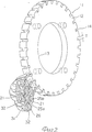
фиг.2 перспективный вид /частично в разрезе/ диска с пластинами для поддержания вспомогательных колес и вспомогательными колесами, установленными на диске;
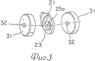
фиг.3 перспективный вид /в разобранном состоянии/, иллюстрирующий способ установки вспомогательных колес на пластине для поддержания вспомогательных колес;
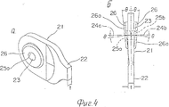
фиг. 4 (а) и (б) перспективный вид и вид сверху, иллюстрирующие соответственно пример пластины для поддержания вспомогательных колес;
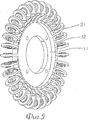
фиг.5 перспективный вид, на котором показано множество пластин для поддержания вспомогательных колес, установленных /пластин/ на диске;
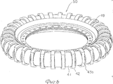
фиг. 6 перспективный вид, иллюстрирующий второй вариант осуществления настоящего изобретения;
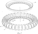
фиг. 7 перспективный вид, иллюстрирующий способ сборки колеса, снабженного вспомогательными колесами, в соответствии с вторым вариантом;
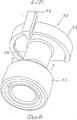
фиг.8 перспективный вид /в разборном состоянии/, иллюстрирующий конструкцию для поддержания вспомогательного колеса во втором варианте;
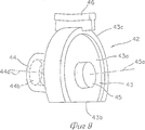
фиг. 9 перспективный вид, показывающий опорный элемент для поддержания вспомогательного колеса во втором варианте осуществления настоящего изобретения;
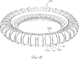
фиг. 10 перспективный вид, иллюстрирующий модификацию второго варианта осуществления настоящего изобретения;
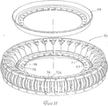
фиг. 11 перспективный вид, иллюстрирующий третий вариант осуществления настоящего изобретения;
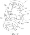
фиг. 12 перспективный вид, показывающий состояние встраивания вспомогательных колес в элемент для поддержания вспомогательных колес в третьем варианте;
фиг.13 перспективный вид предохранителя сочленения;
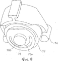
фиг. 14 перспективный вид, иллюстрирующий конструкцию для поддержания вспомогательных колес в третьем варианте;
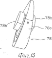
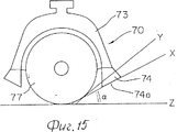
фиг. 15 схематический перспективный вид, иллюстрирующий вращение и торможение вспомогательных колес в третьем варианте;
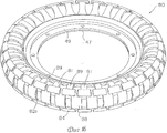
фиг.16 перспективный вид, иллюстрирующий модификацию третьего варианта;
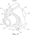
фиг. 17 перспективный вид, иллюстрирующий модификацию опорного элемента для поддержания вспомогательного колеса;
фиг.18 перспективный вид предохранителя сочленения;
фиг.19 перспективный вид модификации вспомогательного колеса;
фиг. 20 перспективный вид /в разобранном состоянии/, иллюстрирующий способ сборки;
фиг.21 перспективный вид одного собранного узла;
фиг. 22 частичный разрез, иллюстрирующий конструкцию для поддержания вспомогательных колес;
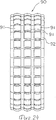
фиг. 23 вид по оси, иллюстрирующий четвертый вариант осуществления настоящего изобретения;
фиг.24 ортогональный вид колеса, показанного на фиг. 23;
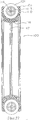
фиг.25 разрез по линии А-А на фиг.23;
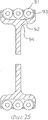
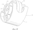
фиг. 26 перспективный вид, иллюстрирующий пятый вариант осуществления настоящего изобретения;
фиг. 27 разрез колеса, снабженного вспомогательными колесами в соответствии с пятым вариантом; и
фиг.28 перспективный вид, иллюстрирующий опору вспомогательного колеса в пятом варианте.Below is a brief description of the drawings, in which:
FIG. 1 is a perspective view showing the appearance of one embodiment of a wheel provided with auxiliary wheels in accordance with the present invention;
figure 2 is a perspective view / partially in section / of a disk with plates for supporting auxiliary wheels and auxiliary wheels mounted on the disk;
figure 3 perspective view / in disassembled state /, illustrating a method of installing auxiliary wheels on the plate to maintain the auxiliary wheels;
FIG. 4 (a) and (b) a perspective view and a top view illustrating respectively an example of a plate for supporting the auxiliary wheels;
5 is a perspective view showing a plurality of plates for supporting the auxiliary wheels mounted / plates / on the disk;
FIG. 6 is a perspective view illustrating a second embodiment of the present invention;
FIG. 7 is a perspective view illustrating a method of assembling a wheel provided with auxiliary wheels in accordance with a second embodiment;
Fig.8 is a perspective view / in a collapsible state / illustrating a structure for supporting the auxiliary wheel in the second embodiment;
FIG. 9 is a perspective view showing a support member for supporting an auxiliary wheel in a second embodiment of the present invention;
FIG. 10 is a perspective view illustrating a modification of a second embodiment of the present invention;
FIG. 11 is a perspective view illustrating a third embodiment of the present invention;
FIG. 12 is a perspective view showing a state of incorporating auxiliary wheels into an element for supporting auxiliary wheels in a third embodiment;
13 is a perspective view of the articulation fuse;
FIG. 14 is a perspective view illustrating a structure for supporting auxiliary wheels in a third embodiment;
FIG. 15 is a schematic perspective view illustrating rotation and braking of auxiliary wheels in a third embodiment;
Fig. 16 is a perspective view illustrating a modification of the third embodiment;
FIG. 17 is a perspective view illustrating a modification of a support member for supporting an auxiliary wheel;
Fig. 18 is a perspective view of an articulation fuse;
Fig.19 is a perspective view of a modification of the auxiliary wheel;
FIG. 20 is a perspective view / disassembled / illustrating an assembly method;
Fig.21 is a perspective view of one assembled node;
FIG. 22 is a partial sectional view illustrating a structure for supporting auxiliary wheels;
FIG. 23 is an axial view illustrating a fourth embodiment of the present invention;
FIG. 24 is an orthogonal view of the wheel of FIG. 23;
Fig.25 section along the line aa in Fig.23;
FIG. 26 is a perspective view illustrating a fifth embodiment of the present invention;
FIG. 27 is a section through a wheel provided with auxiliary wheels in accordance with a fifth embodiment; and
Fig. 28 is a perspective view illustrating the support of the auxiliary wheel in the fifth embodiment.
Ниже со ссылками на чертежи описаны варианты осуществления настоящего изобретения. Embodiments of the present invention are described below with reference to the drawings.
На фиг.1 показан перспективный вид, иллюстрирующий один из вариантов колеса 10, снабженного вспомогательными колесами, в соответствии с настоящим изобретением. 1 is a perspective view illustrating one embodiment of a wheel 10 provided with auxiliary wheels in accordance with the present invention.
Как показано на чертежах, позицией 11 обозначен диск для поддержания всего колеса. Диск 11 снабжен на наружной периферии круглым ободом 12, а в центральной части отверстием 13, в которое вставляют ось или вал /не показаны/ колеса. As shown in the drawings, 11 denotes a disc for supporting the entire wheel. The disk 11 is provided on the outer periphery with a
Как показано на фиг.2, на круглом ободе 12 выполнено множество пазов 14, равномерно распределенных по окружности обода и проходящих в том же направлении, что и ось круглого обода 12. Нижний конец 22 каждой из пластин 21 для поддержания вспомогательных колес входит в соответственный паз 14. As shown in FIG. 2, a plurality of
Каждая из пластин 21 для поддержания вспомогательных колес имеет нижний конец 22, входящий в паз 14, и опору 23 для вспомогательных колес, расположенную на конце, противоположном нижнему концу 22. Each of the
Нижний конец 22 имеет толщину t, которая одинакова с шириной Т паза 14 или несколько больше ее. Опора 23 имеет опорные отверстия, проходящие сквозь пластину 21 и состоящие из двух опорных отверстий 25а и 25b, соответственные оси 24а и 24b которых наклонены каждая под углом θ к линии, перпендикулярной к пластине 21, в сторону нижнего конца 22. Кроме того, опора 23 снабжена двумя наклонными бобышками 26, каждая из которых имеет наклонную поверхность 26а, проходящую под углом q к пластине 21 так, что наклонные поверхности сходятся в направлении к нижнему концу 22, в результате чего опорная длина двух опорных отверстий 25а, 25b увеличивается. Угол q определяется числом пазов 14 на круглом ободе 12, т.е. числом вспомогательных колес, поддерживаемых посредством пластин 21. The
Как показано на фиг.2 и 5, пластины 21 для поддержания вспомогательных колес, имеющие описанную выше конструкцию, неподвижно установлены на наружной периферии круглого обода 12 с равным шагом между ними путем посадки нижних концов 22 пластин 21 в пазы 14 круглого обода 12. As shown in FIGS. 2 and 5, the auxiliary
Пластины 21 прикреплены к наружной периферии круглого обода 12 путем посадки вспомогательных колес 31 в опоры 23 с противоположных сторон пластины 21, как показано на фиг.3. The
Как показано на фиг. 1, 2 и 3, вспомогательные колеса 31 выполнены в форме дисков, каждый из которых снабжен в центре каждой его боковой поверхности выступающей от нее опорной осью 32 вращения. Ширину наружной периферии вспомогательного колеса предпочтительно делают насколько возможно широкой, только чтобы колесо не терлось о боковую сторону нижнего конца пластины 21 для поддержания вспомогательных колес. As shown in FIG. 1, 2 and 3, the
Наружный диаметр вспомогательного колеса 31 таков, что радиально наружная концевая часть колеса, установленного на пластине 21, выступает наружу за пределы крайней наружной части пластины 21. The outer diameter of the
Каждое из вспомогательных колес 31 опирается на каждом его конце на пластину 21 для поддержания вспомогательных колес, при этом опорные оси 31 вращения входят в опорные отверстия 25а, 25b опоры 23 для вспомогательных колес. Для того, чтобы поддерживать вспомогательное колесо 31 с возможностью вращения на его опорных осях 32, как центрах вращения, опорные отверстия 25а, 25b и опорные оси 32 вращения выполняют в виде опорных конструкций. Для таких опорных конструкций могут быть использованы подшипники скольжения, шариковые или роликовые подшипники или т.п. в зависимости от прилагаемой к вспомогательному колесу 31 нагрузки или от его скорости вращения. Each of the
Как показано на фиг.1, крайняя наружная периферийная часть /шина/ 40 колеса 10 образована путем установки каждого из вспомогательных колес с возможностью вращения на опорных пластинах 21 с обеспечением их расположения с одинаковым между ними шагом на наружной периферии круглого обода 12. As shown in FIG. 1, the outermost peripheral portion / tire / 40 of the wheel 10 is formed by mounting each of the auxiliary wheels to rotate on the
Колесо 10, снабженное вспомогательными колесами 31, в соответствии с описанным выше вариантом конструкции, обладает следующими полезными качествами. The wheel 10, equipped with
Колесо 10, снабженное вспомогательными колесами 31, устанавливают на оси /валу/ колеса, используя отверстие 13 диска 11, и оно может быть использовано в качестве колеса, имеющего шину 40, образованную множеством вспомогательных колес 31, установленных по окружности. То есть, когда колесо вращается вокруг вала /не показан/ колеса, оно движется в том же самом направлении, в каком катится шина 40, подобно обычному колесу. A wheel 10 provided with
Вспомогательные колеса 31 вращают независимо каждое вокруг его оси с помощью привода /не показан/ или путем приложения к нему внешней силы в направлении, совпадающем с направлением вала /оси/ колеса. Вращение вспомогательных колес 31 заставляет колесо 10 двигаться в направлении, соответствующем направлению вала колеса /направлении, перпендикулярном к направлению качения шины 40/. Движение колеса можно просто осуществить без необходимости приложения дополнительного усилия также и в состоянии, когда колесо 10 остановлено.
При одновременном осуществлении качения шины 40 и вращения вспомогательных колес 31 колесо 10 движется в направлении суммарного вектора обоих движений. Следовательно, одновременно управляя вращением шины 40 и вращением вспомогательных колес 31, можно перемещать колесо 10 в произвольном направлении, не поворачивая вала колеса. While rolling the tire 40 and rotating the
На фиг. 6 9 показаны виды, иллюстрирующие второй вариант осуществления настоящего изобретения. In FIG. 6 to 9 are views illustrating a second embodiment of the present invention.
В этом варианте опорные элементы 42 для поддержания с возможностью вращения вспомогательных колес 41 выполнены большими по размеру, чем аналогичные элементы в предшествующем варианте, что увеличивает их прочность. In this embodiment, the
Как показано на фиг.9, опорный элемент 42 для поддержания вспомогательного колеса содержит обрезанный наклонный пластинообразный диск 43, полученный путем отрезания нижней части наклонного дискообразного элемента трапециевидного сечения с двумя наклонными поверхностями 43а по поверхности 43 среза, параллельной нижней стороне. Кроме того, обрезанный наклонный диск 43 имеет на наружной периферии наружные периферийные ребра 43с, отходящие наружу в осевом направлении от двух наклонных поверхностей 43а. As shown in FIG. 9, the
Каждая из двухнаклонных поверхностей 43а наклонена в направлении схождения этих поверхностей друг с другом под углом q к поверхности, перпендикулярной к поверхности 43b среза. На одной из двух наклонных поверхностей 43а имеется основная ось 44, а на другой вспомогательная ось 45, причем каждая из этих осей проходит в направлении наружу перпендикулярно к соответственной наклонной поверхности. То есть соответственные геометрические оси 44а и 45а основной оси 44 и вспомогательной оси 45 наклонены под углом q к линии, параллельной поверхности 43b среза. Основная ось 44 снабжена в ее центре отверстием 44b, в которое может быть вставлена вспомогательная ось 45 соседнего элемента 42 для поддержания вспомогательных колес. Each of the two-inclined surfaces 43a is inclined in the direction of convergence of these surfaces with each other at an angle q to the surface perpendicular to the
К противоположному поверхности 43b концу обрезанного наклонного диска 43 прикреплен, по существу, параллельно поверхности 43b среза направляющий элемент 46 в виде бруса Т-образного сечения. A
Как показано на фиг. 8, на основную ось 44 опорного элемента 42 для поддержания вспомогательных колес устанавливают с возможностью вращения полое цилиндрическое вспомогательное колесо 41, диаметр которого меньше, чем диаметр обрезанного наклонного диска 43. В сопрягаемой части между основной осью 44 и вспомогательным колесом 41 устанавливают подшипник, такой, как шариковый или роликовый подшипник или подшипник скольжения /не показан/. As shown in FIG. 8, a hollow cylindrical
Как показано на фиг. 7, опорные элементы 42 с установленными на них соответственными вспомогательными колесами 41 установлены на круглом ободе 47 путем вставления их в множество пазов 48, выполненных на его наружной периферии и проходящих в направлении, соответствующем направлению геометрической оси колеса, причем расположены пазы с одинаковым шагом между ними. As shown in FIG. 7,
Опорные элементы 42 без разрывов устанавливают на наружной периферии круглого обода 47 так, чтобы вспомогательные оси 45 соседних опорных элементов 42 входили в центральные отверстия 44b основной оси 44, в результате чего получают конструкцию, в которой основные оси имеют опору на обоих их концах. The
Затем к ободу 47 прикрепляют крышку 49 обода и получают в результате колесо 50, снабженное вспомогательными колесами 41, как показано на фиг. 6. Это колесо 50 обеспечивает возможность увеличения нагрузки, прилагаемой к каждому вспомогательному колесу 41, благодаря тому, что вспомогательное колесо 41 установлено с возможностью вращения на основной оси 44 большего диаметра, причем свободный конец основной оси 44 установлен на поддерживающей его вспомогательной оси 45 соседнего опорного элемента 42 для поддержания вспомогательных колес. Then, the
Поскольку часть вспомогательного колеса 41 выполнена так, что выступает радиально наружу от поверхности 43b среза опорного элемента 42, то колесо 50 может быть перемещено в направлении, соответствующем направлению вала /оси/ колеса, подобно как в предыдущем варианте. Множество вспомогательных колес, расположенных с одинаковым между ними шагом, образует крайнюю наружную периферийную часть /шину/ колеса 50, в результате чего колесо 50 может двигаться в направлении, соответствующем направлению качения шины, подобно как в случае обычного колеса. Since the part of the
Колесо 50 в соответствии с настоящим изобретением может быть использовано как колесо, к которому прилагают увеличенную нагрузку. Наружный диаметр обрезанного наклонного диска 43, увеличенный по сравнению с диаметром вспомогательного колеса 41, позволяет предотвратить столкновение вспомогательных колес 41 со всяким чужеродным предметом сбоку от колеса 50.
На фиг.10 показан перспективный вид, иллюстрирующий модификацию варианта, показанного на фиг. 6. В колесе 60, снабженном вспомогательными колесами в соответствии с настоящим изобретением, два конца 53b поверхности 53а среза обрезанного диска каждого из опорных элементов 51 для поддержания с возможностью вращения вспомогательных колес 41 закруглены по плавной дуге окружности. 10 is a perspective view illustrating a modification of the embodiment shown in FIG. 6. In the
Поскольку конструкция в иных, чем указано выше, отношениях такая же, как в предыдущем втором варианте, то описание ее не делается. Since the construction in the relations other than indicated above is the same as in the previous second embodiment, its description is not made.
Профиль по дуге окружности на двух концах поверхности 53а среза элемента 51 для поддержания вспомогательных колес обеспечивает плавную конфигурацию наружной периферии колеса 60, в результате чего происходит меньше столкновений части опорного элемента 51 с грунтом при качении колеса 60 и перемещении вспомогательных колес 41 в направлении вала /оси/ колеса в результате вращения вспомогательных колес. Колесо 60 в соответствии с данным вариантом особенно пригодно в случае, когда колесо используют в наклонном положении. The profile along the circular arc at the two ends of the cutoff surface 53a of the auxiliary
На фиг.11 15 показаны виды, иллюстрирующие третий вариант осуществления настоящего изобретения. 11 to 15 are views illustrating a third embodiment of the present invention.
В этом варианте опорный элемент для поддержания вспомогательных колес снабжен на обоих концах его поверхности среза упругими элементами, изготовленными из чего-либо подобного резине. На фиг.12 показан опорный элемент 71 для поддержания вспомогательных колес, использованный в данном варианте. Опорный элемент 71 содержит обрезанный дискообразный элемент 72, выполненный путем отрезания части дискообразного элемента по поверхности 72а среза, параллельной диаметральному направлению, и обод 73, образованной по наружной периферии обрезанного дискообразного элемента 72. На противоположном поверхности 72а среза конце к ободу 73 прикреплен параллельно оси обрезанного дискообразного элемента 72 направляющий элемент 76 в виде бруска Т-образного сечения. Обод 73 снабжен на его обоих концах краевыми резиновыми элементами 74, каждый из которых имеет наклонную поверхность 74а, расположенную с обеспечением расхождения в направлении наружу, причем каждый краевой резиновый элемент 74 выступает от поверхности 72а среза. Кроме того, обрезанный дискообразный элемент 72 снабжен в центре каждой из его боковых сторон осью 75 для поддержания вспомогательных колес, выступающей от него и имеющей отверстие 75а, содержащее прямолинейную часть. Оси 75 проходят перпендикулярно к образованному дискообразному элементу 72. In this embodiment, the support element for supporting the auxiliary wheels is provided at both ends of its shear surface with elastic elements made of something like rubber. 12 shows a
Каждое из полых цилиндрических вспомогательных колес 77 установлено с возможностью вращения вокруг осей 75 с противоположных сторон обрезанного дискообразного элемента 72. Как показано на фиг.14, каждому из вспомогательных колес 77, установленных на осях 75, предназначен предохранитель 78 сочленения. Как показано на фиг.13, предохранитель 78 сочленения содержит клиновидную пластину 78а, выполненную с обеспечением угла q между ее противоположными поверхностями, и две короткие оси 78b, отходящие от обеих поверхностей клиновидной пластины 78а в перпендикулярном к ним направлении. Каждая короткая ось 78b имеет сечение, подходящее для вставления в центральное отверстие 75а оси 75 для поддержания вспомогательного колеса. Each of the hollow cylindrical
Каждый предохранитель 78 сочленения установлен на каждом вспомогательном колесе 77 так, что более толстая его сторона направлена в сторону поверхности 72а среза обрезанного дискообразного элемента 72, причем короткие оси 78b предохранителя 78 обеспечивают сплошное /неразрывное/ соединение опорных осей 75 соседних элементов 71 для поддержания вспомогательных колес. Each
Колесо 70, снабженное вспомогательными колесами, получают, как показано на фиг. 11, путем вставления направляющих элементов 76 опорного элемента 71 с установленными на нем с возможностью вращения вспомогательными колесами 77 в множество пазов 48, выполненных на наружной периферии круглого обода 47 с одинаковым между ними шагом, как и в предыдущих вариантах. A
Колесо 70 в соответствии с данным вариантом действует так, что, когда оно имеет наклон более заданного угла, это заставляет резиновый край 74 входить в контакт с полом и, следовательно, тормозить вращение вспомогательных колес 77. То есть, как показано на фиг. 15, когда колесо 70 наклонено на угол a и положение Z пола приходит в положение X, резиновый край 74 начинает входить в контакт с полом в положении X. The
При дальнейшем наклоне колеса 70, пока положение пола не изменится с X на Y, упругая деформация резинового края 74 достигает предела, и вспомогательное колесо 77 отходит от пола У. Это прекращает движение вспомогательного колеса 77 в направлении, перпендикулярном направлению движения колеса 70, вследствие вращения вспомогательного колеса 77. Следовательно, колесо 70 движется в направлении вращения основного его вала /оси/ в результате контакта резинового края 74 с полом У. With further inclination of the
Это действие дает особенно превосходные результаты в случае, когда колесо 70 в соответствии с данным вариантом используют для спортивного устройства, движущегося на уклоне. Например, колесо 70 в соответствии с данным вариантом может быть прикреплено к продолговатой доске, на которую оператор может поставить одну ногу, для создания тем самым движущегося устройства. Если имеется пара движущихся устройств и оператор движется на уклоне, поставив каждую ногу на одно из движущихся устройств, он может при этом совершать боковое скользящее движение, как будто при скольжении на обычных лыжах, и потому может регулировать скорость движения и его направление. This action gives particularly excellent results when the
Кроме того, поскольку в колесе 70 в соответствии с данным вариантом оси 75 для поддержания вспомогательных колес поддерживают в опорной конструкции посредством предохранителей 78 сочленения на обоих концах, то вспомогательные колеса 77 могут быть нагружены большой нагрузкой. In addition, since in the
На фигурах 16-22 показаны виды, иллюстрирующие модификацию третьего варианта осуществления настоящего изобретения, описанного выше. Figures 16-22 are views illustrating a modification of a third embodiment of the present invention described above.
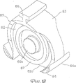
В этом варианте элемент для поддержания вспомогательных колес снабжен на обоих концах его поверхности среза упругими элементами /такими, как резина/, как в третьем варианте. На фиг. 17 показан элемент 81 для поддержания вспомогательных колес, использованный для данного варианта. Этот опорный элемент 81 содержит обрезанный дискообразный элемент 82, выполненный путем отрезания части дискообразного элемента по поверхности 82а среза, параллельно диаметральному направлению, и обод 83, образованный по наружной периферии обрезанного дискообразного элемента 82. К противоположному поверхности 82а среза концу обода 83 прикреплен параллельно оси образованного дискообразного элемента 82 направляющий элемент 86 в виде бруса Т-образного сечения. К двум концам обода 83 прикреплены краевые резиновые элементы 84 с наклонными поверхностями, расположенными с обеспечением их расхождения в направлении наружу, причем краевые резиновые элементы выступают от поверхности 82а среза. Две боковые поверхности обрезанного дискообразного элемента 82 наклонены под углом q в сторону направляющего элемента 86 и снабжены каждая выступающей осью 85 для поддержания вспомогательного колеса, имеющей отверстие 85а. Кроме того, вокруг оси 85 выполнен выступ 82 и вспомогательным колесом 88, как при лабиринтном уплотнении. Каждые ось 85 и выступ 87 расположены перпендикулярно к боковым поверхностям обрезанного дискообразного элемента 82. In this embodiment, the element for supporting the auxiliary wheels is provided at both ends of its shear surface with elastic elements / such as rubber /, as in the third embodiment. In FIG. 17 shows an auxiliary
На фиг.18 показан предохранитель сочленения, использованный в сочетании с элементом 81 для поддержания вспомогательных колес. Этот предохранитель 89 имеет, по существу, такую же конфигурацию, как и элемент 81 для поддержания вспомогательных колес, и снабжен, вместо оси 85 для поддержания вспомогательного колеса, осями 85b шарнира выполнена в форме, обеспечивающей вставление ее в центральное отверстие оси 85 для поддержания вспомогательного колеса. Для частей иных, чем описаны выше, использованы те же номера позиций, что и на фиг.17, и их описание исключено. On Fig shows the articulation fuse used in combination with
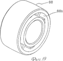
Каждое полое цилиндрическое вспомогательное колесо 88 снабжено углублением /выточкой/ 88b, служащим для образования лабиринтного уплотнения, как показано на фиг.18. Вспомогательные колеса 88 устанавливают с возможностью вращения на осях 85 с обоих концов элемента 81 для поддержания вспомогательных колес, как показано на фигурах 20-22. Каждый из выступов 87 входит в углубление 88b вспомогательного колеса 88, в результате чего образуется лабиринтное уплотнение. Предохранители 89 сочленения присоединяют к осям 85 с установленными на них вспомогательными колесами 88 так, чтобы оси 85b шарнира входили в центральное отверстие 85а. Оси 85 для поддержания вспомогательных колес соединяют посредством осей 85b предохранителей 89 так, чтобы они образовывали сплошное /неразрывное/ соединение. Each hollow cylindrical
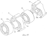
Показанное на фиг. 16 колесо 80, снабженное вспомогательными колесами, собирают из опорных элементов 81 с установленными на них с возможностью вращения вспомогательными колесами 88 и присоединенными к ним предохранителями 89 сочленения, вставляя направляющие элементы 86 в множество пазов 48, выполненных на наружной окружности круглого обода 47, и затем, как и в вышеописанном втором варианте, прикрепляют к ободу 47 крышку 49. Shown in FIG. 16, a
Когда колесо 80 в соответствии с данным вариантом наклоняется на угол, превышающий заданный угол, краевые резиновые элементы входят в соприкосновение с полом и выполняют функцию торможения вращения вспомогательных колес 88, как и в третьем варианте. Кроме того, комбинация выступов 87 с вспомогательными колесами 88 образует лабиринтные уплотнения, которые предотвращают вхождение инородного вещества снаружи в зазоры между опорной осью 85 и вспомогательными колесами 88. When the
Кроме того, чередующаяся комбинация предохранителей 89 с элементами 81 для поддержания вспомогательных колес обеспечивает возможность увеличения, по сравнению с третьим вариантом, ширины вспомогательного колеса 88, которое может быть поддержано посредством опорного элемента 81. In addition, the alternating combination of
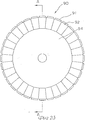
На фиг.23 25 показан четвертый вариант осуществления настоящего изобретения. В колесе 90 в соответствии с этим вариантом по наружной его периферии установлено множество комплектов вспомогательных колес. Каждый компонент содержит несколько установленных последовательно вспомогательных колес 91 /в данном варианте три вспомогательных колеса с параллельными осями. То есть колесо 90 составляют, устанавливая три вспомогательных колеса 91 с возможностью вращения каждое на центральной поддерживающей оси 93 в каждом из множества блоков 92 для поддержания вспомогательных колес /вспомогательные колеса несколько выступают из них/, причем блоки 92 располагают на наружной периферии дискообразного обода 94 с одинаковым шагом. 23 to 25 show a fourth embodiment of the present invention. In the
Данный вариант с несколькими последовательно расположенными вспомогательными колесами 91 обеспечивает возможность увеличения ширины колеса 90, благодаря чему может быть увеличена прилагаемая к колесу 90 нагрузка. This embodiment with several
На фиг. 26 28 показаны виды, иллюстрирующие пятый вариант осуществления настоящего изобретения. В колесе 100, снабженном вспомогательными колесами в соответствии с настоящим изобретением, между соответственными вспомогательными колесами расположены упругие промежуточные элементы. Эти упругие промежуточные элементы образуют наружную периферийную окружность, имеющую, по существу, такой же диаметр, как у наружной периферийной окружности, образованной всеми вспомогательными колесами, установленными на колесе. In FIG. 26 to 28 are views illustrating a fifth embodiment of the present invention. In the
В этом варианте на наружную периферийную окружность круглого обода 47 насажен закрывающий элемент 103, изготовленный из эластичного материала, такого, как резина. Закрывающий элемент 103 снабжен на наружной периферии множеством сквозных проемов 102, ширина которых позволяет установку вспомогательных колес 101, причем эти проемы 102 расположены в круговом направлении на одинаковом расстоянии друг от друга. Между соседними проемами 102 расположены промежуточные элементы 105, снабженные несколькими радиальными выступами 104 /на фиг.26 три выступа в середине и на правой и левой сторонах). In this embodiment, a
Указанные выступы 105 выполнены так, что диаметр окружности, образованной совместно центральными выступами 104 промежуточных элементов 105, расположенных в круговом направлении, по существу, равен диаметру окружности шины, образованной всеми вспомогательными колесами 101, расположенными по окружности. These
Как показано на фиг.28, каждое вспомогательное колесо 101 установлено с возможностью вращения в опоре 110, имеющей цилиндрическую поверхность 111, закрепляемую на ободе, причем часть вспомогательного колеса 101 выступает в сторону, противоположную поверхности 111. Т.е. опора 110 для вспомогательного колеса снабжена полыми цилиндрическими частями 112, концентрическими с поверхностью 111, закрепляемой на ободе. Ось 114 вращения вспомогательного колеса 101 поддерживают на обоих концах в полых цилиндрических частях 112 посредством опорных элементов, таких, как шарикоподшипники и роликоподшипники. As shown in FIG. 28, each
Как показано на фиг.27, опору 110 вспомогательного колеса устанавливают так, чтобы упругий элемент 116 был расположен между наружной периферийной поверхностью круглого обода 47 в его средней части и поверхностью 111, закрепляемой на ободе, и полые цилиндрические части 112 были закрыты промежуточными элементами 105 закрывающего элемента 103. Установку опоры 111 вспомогательного колеса предпочтительно осуществляют после установки в ней вспомогательного колеса 101, как показано на фиг.28. As shown in FIG. 27, the
Поскольку в колесе 100 в соответствии с данным вариантом поверхности вспомогательных колес 101, входящие в контакт с грунтом, и поверхности центральных выступов 104 промежуточных элементов 105, входящие в контакт с грунтом, расположены, по существу, на одной и той же окружности, то вспомогательные колеса 101 и промежуточные элементы 105 входят в контакт с грунтом поочередно, когда колесо 100 движется прямо вперед. Since in the
Это обеспечивает плавное вращательное движение колеса 100, что позволяет уменьшить вибрацию колеса при его движении. Кроме того, поскольку прилагаемая к колесу 100 нагрузка может быть воспринята и вспомогательными колесами 101, и промежуточными элементами 105, то нагрузка, прилагаемая к колесу 100, может быть увеличена. This provides a smooth rotational movement of the
Кроме того, в колесе 100 в соответствии с данным вариантом при наклоне его во время движения выступы 104 промежуточных элементов 105 упруго деформируются пропорционально наклону, не мешая движению колеса 100 в прямом направлении, и в перпендикулярном к нему направлении. In addition, in the
Кроме того, когда колесо 100 наклоняется на угол больше заданного, выступы 104 промежуточных элементов 105 также упруго деформируются настолько, чтобы не вызвать чрезмерного трения между полом и выступами. In addition, when the
Как описано выше, настоящее изобретение позволяет изменять направление движения колеса произвольно и просто без описания им траектории по дуге окружности. Кроме того, поскольку нет необходимости в ручке управления для вала /оси/ колеса и выполнения операции переключения в зависимости от направления движения, то конструкция для установки колеса проста, и не требуется сложная и больших размеров конструкция колеса. As described above, the present invention allows you to change the direction of movement of the wheel arbitrarily and simply without describing the path along a circular arc. In addition, since there is no need for a control knob for the shaft / axle / wheel and to perform a shift operation depending on the direction of travel, the design for installing the wheel is simple, and the complex and large size wheel design is not required.
Колесо, снабженное вспомогательными колесами в соответствии с настоящим изобретением, может быть использовано в качестве отдельной конструкции, подобно традиционному колесу, но особенно эффективно оно при использовании в транспортных средствах, требующих изменения направления движения в узком пространстве, рабочих роботах, требующих изменения направления движения без описания траектории по дуге окружности, или в качестве ходового колеса в спортивных устройствах, требующих особого управления. A wheel equipped with auxiliary wheels in accordance with the present invention can be used as a separate structure, similar to a traditional wheel, but it is especially effective when used in vehicles requiring a change of direction in narrow space, working robots requiring a change in direction without description trajectories along an arc of a circle, or as a running wheel in sports devices requiring special control.
Claims (6)
Applications Claiming Priority (3)
| Application Number | Priority Date | Filing Date | Title |
|---|---|---|---|
| JP199636/1991 | 1991-08-08 | ||
| JP19963691 | 1991-08-08 | ||
| PCT/JP1992/000952 WO1993002872A1 (en) | 1991-08-08 | 1992-07-27 | Composite wheel device |
Publications (2)
| Publication Number | Publication Date |
|---|---|
| RU93034796A RU93034796A (en) | 1995-05-20 |
| RU2090373C1 true RU2090373C1 (en) | 1997-09-20 |
Family
ID=16411146
Family Applications (1)
| Application Number | Title | Priority Date | Filing Date |
|---|---|---|---|
| RU9293034796A RU2090373C1 (en) | 1991-08-08 | 1992-07-27 | Wheel with auxiliary wheels |
Country Status (20)
| Country | Link |
|---|---|
| US (1) | US5383715A (en) |
| EP (1) | EP0556401B1 (en) |
| JP (1) | JP3381848B2 (en) |
| KR (1) | KR930702170A (en) |
| CN (1) | CN1041071C (en) |
| AT (1) | ATE161778T1 (en) |
| AU (1) | AU667050B2 (en) |
| BR (1) | BR9205338A (en) |
| CA (1) | CA2093520A1 (en) |
| DE (1) | DE69223941T2 (en) |
| DK (1) | DK0556401T3 (en) |
| ES (1) | ES2111646T3 (en) |
| FI (1) | FI931563A7 (en) |
| GE (1) | GEP19981424B (en) |
| NO (1) | NO178488C (en) |
| NZ (1) | NZ243899A (en) |
| RU (1) | RU2090373C1 (en) |
| SG (1) | SG52573A1 (en) |
| TW (1) | TW211546B (en) |
| WO (1) | WO1993002872A1 (en) |
Cited By (1)
| Publication number | Priority date | Publication date | Assignee | Title |
|---|---|---|---|---|
| RU2518760C1 (en) * | 2013-03-26 | 2014-06-10 | Николай Петрович Дядченко | Wheel without hub |
Families Citing this family (51)
| Publication number | Priority date | Publication date | Assignee | Title |
|---|---|---|---|---|
| US5553874A (en) * | 1994-09-06 | 1996-09-10 | Schouten; Pieter | Truck assembly for roller board apparatus |
| GB2302866A (en) * | 1995-06-30 | 1997-02-05 | Lanton Park Ltd | Process and Apparatus for Recycling Airborne Particulate Matter |
| US5720529A (en) * | 1996-12-20 | 1998-02-24 | Barron; Bruce J. | Roller skate wheel |
| DE19703285A1 (en) * | 1997-01-30 | 1998-08-06 | Estebanez Eva Garcia | Wheel with elastic tyre |
| WO1998041295A1 (en) | 1997-03-17 | 1998-09-24 | Viktor Schatz | Wheel and belt drive with transversal brake |
| US6516848B1 (en) * | 1999-05-18 | 2003-02-11 | Anthony Italo Provitola | Toroidal wheel |
| US6250355B1 (en) | 1999-05-19 | 2001-06-26 | Anthony Italo Provitola | Wheel and tire structure |
| AU1905001A (en) * | 1999-10-11 | 2001-04-23 | Vladimir Valentinovich Prokhorov | 2-dimensional support and propulsion device and variants thereof, frictional direction stabilizer, t-square and coordinate measurement device |
| US6672931B1 (en) * | 2000-11-14 | 2004-01-06 | Jim Bagley | Interconnectable model construction elements |
| JP2003063202A (en) * | 2001-08-24 | 2003-03-05 | Kyosho Corp | Traveling body wheels |
| WO2004071607A2 (en) * | 2003-02-07 | 2004-08-26 | Gracewood, Inc. | Improved interconnectable model construction elements |
| US7069699B2 (en) * | 2003-02-19 | 2006-07-04 | Anthony Italo Provitola | Toroidal frameworks connection |
| US7311329B2 (en) | 2003-05-23 | 2007-12-25 | Pride Mobility Products Corporation | Anti-tip wheel for a wheelchair |
| US7056185B1 (en) | 2004-10-04 | 2006-06-06 | Thomas Anagnostou | Single axle wireless remote controlled rover with omnidirectional wheels |
| WO2006068007A1 (en) * | 2004-12-20 | 2006-06-29 | Shinichiro Fuji | Omnidirectionally moving wheel, moving device, carrying device, and massage device |
| US7730978B2 (en) * | 2006-06-30 | 2010-06-08 | Donald Dixon | All-terrain robotic omni-directional drive assembly |
| US8025551B2 (en) * | 2006-09-20 | 2011-09-27 | Mattel, Inc. | Multi-mode three wheeled toy vehicle |
| US7878284B1 (en) * | 2007-11-29 | 2011-02-01 | Shultz Jonathan D | Omni-directional tread and contiguous moving surface |
| US8827375B2 (en) * | 2008-12-05 | 2014-09-09 | Honda Motor Co., Ltd. | Wheel, and friction drive device and omni-directional vehicle using the same |
| JP5506231B2 (en) | 2009-04-15 | 2014-05-28 | 本田技研工業株式会社 | Wheel, friction drive using the same, and omnidirectional vehicle |
| JP5303411B2 (en) * | 2009-09-18 | 2013-10-02 | 本田技研工業株式会社 | Friction type driving device and inverted pendulum type moving body |
| US8408339B2 (en) * | 2010-10-12 | 2013-04-02 | Honda Motor Co., Ltd. | Frictional drive device and inverted pendulum type vehicle using the same |
| FR2991629B1 (en) * | 2012-06-12 | 2015-08-07 | New Live | OMNIDIRECTIONAL WHEEL |
| KR101380249B1 (en) * | 2012-06-19 | 2014-04-01 | 정화 양 | Fabricated wheel |
| JP5910426B2 (en) * | 2012-09-07 | 2016-04-27 | トヨタ自動車東日本株式会社 | Omni-directional wheel, omni-directional wheel unit and moving body |
| FR3006239B1 (en) | 2013-05-28 | 2016-07-29 | Decathlon Sa | TIRE ROOM |
| JP5778740B2 (en) | 2013-10-29 | 2015-09-16 | Whill株式会社 | Omnidirectional moving wheel and omnidirectional moving vehicle equipped with the same |
| JP5687325B1 (en) * | 2013-11-08 | 2015-03-18 | Whill株式会社 | Omnidirectional moving wheel and omnidirectional moving vehicle equipped with the same |
| JP5988952B2 (en) | 2013-11-14 | 2016-09-07 | 本田技研工業株式会社 | Wheel, wheel device and inverted pendulum type vehicle |
| JP6465887B2 (en) | 2013-11-30 | 2019-02-06 | サウジ アラビアン オイル カンパニー | Magnetic omni wheel |
| RU2576229C1 (en) * | 2015-02-04 | 2016-02-27 | Николай Петрович Дядченко | Ring roller |
| US10537764B2 (en) | 2015-08-07 | 2020-01-21 | Icon Health & Fitness, Inc. | Emergency stop with magnetic brake for an exercise device |
| US10625137B2 (en) | 2016-03-18 | 2020-04-21 | Icon Health & Fitness, Inc. | Coordinated displays in an exercise device |
| US10493349B2 (en) | 2016-03-18 | 2019-12-03 | Icon Health & Fitness, Inc. | Display on exercise device |
| US10239347B2 (en) * | 2016-05-18 | 2019-03-26 | Saudi Arabian Oil Company | Magnetic omni-wheel with roller bracket |
| TWI637770B (en) | 2016-11-01 | 2018-10-11 | 美商愛康運動與健康公司 | Drop-in pivot configuration for stationary bikes |
| US10625114B2 (en) | 2016-11-01 | 2020-04-21 | Icon Health & Fitness, Inc. | Elliptical and stationary bicycle apparatus including row functionality |
| US10702736B2 (en) | 2017-01-14 | 2020-07-07 | Icon Health & Fitness, Inc. | Exercise cycle |
| CN106945462B (en) * | 2017-03-15 | 2023-05-30 | 山东蓬翔汽车有限公司 | Lightweight long-life hub unit assembly |
| US10654324B2 (en) * | 2017-11-27 | 2020-05-19 | Lindsay Corporation | Airless flexible tire with torque reducing track pattern |
| CN107984967A (en) * | 2017-12-28 | 2018-05-04 | 内江师范学院 | A kind of omni-directional wheel of high accuracy positioning |
| CN107933120A (en) * | 2017-12-28 | 2018-04-20 | 内江师范学院 | A kind of unlimited printer of intelligence |
| CN111251781B (en) * | 2018-11-19 | 2025-04-25 | 椅夫健康(厦门)智能科技有限公司 | A welded shaft for a universal wheel, a wheel assembly thereof, and a universal wheel |
| CA3043879A1 (en) * | 2019-05-21 | 2020-11-21 | Stephen Sutherland | Shock-tolerant omni wheel |
| US11878551B2 (en) * | 2020-08-12 | 2024-01-23 | Anhui JBH Medical Apparatus Co., Ltd. | Omnidirectional wheel and scooter having omnidirectional wheel |
| CN115107412B (en) * | 2021-05-11 | 2025-06-06 | 上海邦邦机器人有限公司 | Omnidirectional wheel and mobile device |
| CN113443063B (en) * | 2021-07-27 | 2022-05-03 | 哈尔滨轮速科技有限公司 | Electric power-assisted bicycle |
| CN114953849B (en) * | 2022-06-20 | 2023-07-25 | 南京航空航天大学 | A spoke-type non-pneumatic wheel with hollow structure of bionic stick insect tibia |
| CN220096035U (en) * | 2023-04-03 | 2023-11-28 | 广东群旺科技股份有限公司 | Roller support type multi-piece universal wheel |
| CN219749396U (en) * | 2023-04-03 | 2023-09-26 | 广东群旺科技股份有限公司 | Multi-piece universal wheel |
| CN219749397U (en) * | 2023-04-03 | 2023-09-26 | 广东群旺科技股份有限公司 | Multi-piece universal wheel |
Family Cites Families (10)
| Publication number | Priority date | Publication date | Assignee | Title |
|---|---|---|---|---|
| US1305535A (en) * | 1919-06-03 | Vehicle-wheei | ||
| DE2619098A1 (en) | 1976-05-03 | 1977-11-24 | Wienker Ulrich Wilhelm Dipl In | Roller mounted chassis for rotatable office chairs - has universal rollers for instant movement in any direction without tilt |
| JPS57139406A (en) * | 1981-02-24 | 1982-08-28 | Sumitomo Metal Ind Ltd | Production of steel strip |
| JPS57139406U (en) * | 1981-02-26 | 1982-08-31 | ||
| JPS5830424A (en) * | 1981-08-15 | 1983-02-22 | Nippon Denso Co Ltd | Control method of electronically controlled fuel injection |
| JPS5830424U (en) * | 1981-08-22 | 1983-02-28 | 株式会社島津製作所 | mobile trolley |
| JPS59109402A (en) * | 1982-12-16 | 1984-06-25 | Agency Of Ind Science & Technol | Wheel |
| US4926952A (en) * | 1984-05-01 | 1990-05-22 | Jeffrey Farnam | Four-wheel drive wheelchair with compound wheels |
| AU561380B2 (en) * | 1984-10-04 | 1987-05-07 | Oscar Investments Pty. Limited | Wheel composed of rollers |
| DE3702660A1 (en) * | 1987-01-29 | 1988-08-11 | Guenter Schneider | Wheel |
-
1992
- 1992-07-27 RU RU9293034796A patent/RU2090373C1/en active
- 1992-07-27 DK DK92916217.0T patent/DK0556401T3/en active
- 1992-07-27 JP JP50346493A patent/JP3381848B2/en not_active Expired - Lifetime
- 1992-07-27 AU AU23464/92A patent/AU667050B2/en not_active Ceased
- 1992-07-27 US US07/969,225 patent/US5383715A/en not_active Expired - Lifetime
- 1992-07-27 SG SG1996006264A patent/SG52573A1/en unknown
- 1992-07-27 DE DE69223941T patent/DE69223941T2/en not_active Expired - Fee Related
- 1992-07-27 KR KR1019930701055A patent/KR930702170A/en not_active Ceased
- 1992-07-27 GE GEAP19922535A patent/GEP19981424B/en unknown
- 1992-07-27 CA CA002093520A patent/CA2093520A1/en not_active Abandoned
- 1992-07-27 FI FI931563A patent/FI931563A7/en not_active Application Discontinuation
- 1992-07-27 AT AT92916217T patent/ATE161778T1/en active
- 1992-07-27 WO PCT/JP1992/000952 patent/WO1993002872A1/en not_active Ceased
- 1992-07-27 BR BR9205338A patent/BR9205338A/en not_active IP Right Cessation
- 1992-07-27 EP EP92916217A patent/EP0556401B1/en not_active Expired - Lifetime
- 1992-07-27 ES ES92916217T patent/ES2111646T3/en not_active Expired - Lifetime
- 1992-07-31 TW TW081106077A patent/TW211546B/zh active
- 1992-08-08 CN CN92109283A patent/CN1041071C/en not_active Expired - Fee Related
- 1992-08-10 NZ NZ243899A patent/NZ243899A/en unknown
-
1993
- 1993-04-06 NO NO931305A patent/NO178488C/en unknown
Non-Patent Citations (1)
| Title |
|---|
| Патент США N 1305535, кл. 21-19, 1919. * |
Cited By (1)
| Publication number | Priority date | Publication date | Assignee | Title |
|---|---|---|---|---|
| RU2518760C1 (en) * | 2013-03-26 | 2014-06-10 | Николай Петрович Дядченко | Wheel without hub |
Also Published As
| Publication number | Publication date |
|---|---|
| ATE161778T1 (en) | 1998-01-15 |
| US5383715A (en) | 1995-01-24 |
| JP3381848B2 (en) | 2003-03-04 |
| DE69223941T2 (en) | 1998-07-30 |
| SG52573A1 (en) | 1998-09-28 |
| DE69223941D1 (en) | 1998-02-12 |
| CA2093520A1 (en) | 1993-02-09 |
| NO178488C (en) | 1996-04-10 |
| NO178488B (en) | 1996-01-02 |
| KR930702170A (en) | 1993-09-08 |
| WO1993002872A1 (en) | 1993-02-18 |
| AU667050B2 (en) | 1996-03-07 |
| CN1041071C (en) | 1998-12-09 |
| NZ243899A (en) | 1995-07-26 |
| FI931563L (en) | 1993-05-21 |
| TW211546B (en) | 1993-08-21 |
| AU2346492A (en) | 1993-03-02 |
| NO931305D0 (en) | 1993-04-06 |
| CN1069233A (en) | 1993-02-24 |
| BR9205338A (en) | 1993-10-13 |
| GEP19981424B (en) | 1998-10-30 |
| ES2111646T3 (en) | 1998-03-16 |
| EP0556401A4 (en) | 1993-12-29 |
| EP0556401A1 (en) | 1993-08-25 |
| DK0556401T3 (en) | 1998-03-23 |
| FI931563A7 (en) | 1993-05-21 |
| FI931563A0 (en) | 1993-04-06 |
| NO931305L (en) | 1993-05-25 |
| EP0556401B1 (en) | 1998-01-07 |
Similar Documents
| Publication | Publication Date | Title |
|---|---|---|
| RU2090373C1 (en) | Wheel with auxiliary wheels | |
| JPWO1993002872A1 (en) | composite wheel device | |
| JP3690821B2 (en) | Double row angular contact ball bearings for wheels | |
| CA1145151A (en) | Slidable type constant velocity universal joint | |
| US5071265A (en) | Hollow roller bearing assembly for both radial and axial loads | |
| US5388623A (en) | Elastic wheels and a pair of skis provided with the elastic wheels | |
| RU98104067A (en) | DEVICE FOR WHEELS AND BRAKE DISC FOR HEAVY-DUTY VEHICLES | |
| EP0789152B1 (en) | Rolling bearing with a sealing device | |
| EP1182057B1 (en) | Wheel having rotating bodies | |
| US5720529A (en) | Roller skate wheel | |
| CA1163283A (en) | Face seal with rotatable seal ring | |
| US4995850A (en) | Homokinetic coupling having a guiding device having a radial spring force action | |
| US4138169A (en) | Two row rolling bearing assembly having single piece inner ring and two piece outer ring | |
| US5507094A (en) | Wheel bearing assembly with dual telescoping outer rings and improved load support | |
| EP0244064B1 (en) | Telescopic tripot universal joint | |
| KR20240114555A (en) | Wheel assembly | |
| CA1167503A (en) | Wheel bearing assemblies | |
| EP0054797B1 (en) | Twin wheeled castor | |
| US4878881A (en) | Fixed homokinetic joint for transmissions of driving wheels of automobile vehicles | |
| JPH07205852A (en) | Single projection drive type sprocket for rubber crawler | |
| US4135763A (en) | Wheels for roller skates and the like | |
| CN120902461A (en) | Wheel | |
| US6964211B1 (en) | Steering column with improved housing | |
| JPH02262000A (en) | Wheel unit | |
| JP2939564B2 (en) | Rotating wheel for door car |