CN106586585B - Sorting and positioning feeder - Google Patents
Sorting and positioning feeder Download PDFInfo
- Publication number
- CN106586585B CN106586585B CN201710029509.2A CN201710029509A CN106586585B CN 106586585 B CN106586585 B CN 106586585B CN 201710029509 A CN201710029509 A CN 201710029509A CN 106586585 B CN106586585 B CN 106586585B
- Authority
- CN
- China
- Prior art keywords
- positioning
- sorting
- horizontal feeding
- cylinder
- rack
- Prior art date
- Legal status (The legal status is an assumption and is not a legal conclusion. Google has not performed a legal analysis and makes no representation as to the accuracy of the status listed.)
- Active
Links
Images


Classifications
-
- B—PERFORMING OPERATIONS; TRANSPORTING
- B65—CONVEYING; PACKING; STORING; HANDLING THIN OR FILAMENTARY MATERIAL
- B65G—TRANSPORT OR STORAGE DEVICES, e.g. CONVEYORS FOR LOADING OR TIPPING, SHOP CONVEYOR SYSTEMS OR PNEUMATIC TUBE CONVEYORS
- B65G61/00—Use of pick-up or transfer devices or of manipulators for stacking or de-stacking articles not otherwise provided for
-
- B—PERFORMING OPERATIONS; TRANSPORTING
- B65—CONVEYING; PACKING; STORING; HANDLING THIN OR FILAMENTARY MATERIAL
- B65G—TRANSPORT OR STORAGE DEVICES, e.g. CONVEYORS FOR LOADING OR TIPPING, SHOP CONVEYOR SYSTEMS OR PNEUMATIC TUBE CONVEYORS
- B65G47/00—Article or material-handling devices associated with conveyors; Methods employing such devices
- B65G47/02—Devices for feeding articles or materials to conveyors
- B65G47/04—Devices for feeding articles or materials to conveyors for feeding articles
- B65G47/06—Devices for feeding articles or materials to conveyors for feeding articles from a single group of articles arranged in orderly pattern, e.g. workpieces in magazines
Landscapes
- Engineering & Computer Science (AREA)
- Mechanical Engineering (AREA)
- Sheets, Magazines, And Separation Thereof (AREA)
Abstract
The invention relates to a sorting and positioning feeder. It comprises a frame; the left and right sorting mechanisms are used for sorting the stacked materials one by one on the horizontal feeding belts of the left and right horizontal feeding mechanisms; the left and right material supporting mechanisms are used for supporting materials; the left and right horizontal feeding mechanisms are used for conveying the materials on the two sides of the rack one by one to the middle positioning discharging mechanism for positioning; the driving mechanism is used for driving the horizontal feeding belts of the left and right horizontal feeding mechanisms to feed materials to the middle of the rack; the middle positioning discharging mechanism is used for positioning materials. The automatic material distributing, feeding, middle positioning and discharging and other operations on two sides of the rack can be realized through the driving mechanism, the left and right sorting mechanisms, the left and right material supporting mechanisms, the left and right horizontal feeding mechanisms and the middle positioning and discharging mechanism.
Description
Technical Field
The invention relates to a material sorting and conveying device, in particular to a sorting and positioning feeder.
Background
The existing conveying device of the material machine cannot completely and automatically sort materials, cannot separate the materials one by one, cannot automatically position and output the materials, and has low automation degree and greatly reduced working efficiency.
Disclosure of Invention
The invention aims to overcome the defects in the prior art and provide the sorting and positioning feeder which is simple and reasonable in structure, can realize automatic sorting, positioning and discharging, and is high in automation degree and working efficiency.
The purpose of the invention is realized as follows:
a sorting and positioning feeder comprises a rack, a left sorting mechanism, a right sorting mechanism, a left material supporting mechanism, a driving mechanism, a right material supporting mechanism, a left horizontal feeding mechanism, a right horizontal feeding mechanism and a middle positioning discharging mechanism.
The left and right sorting mechanisms are respectively positioned at two sides of the rack and used for sorting stacked materials one by one on a horizontal feeding belt of the left and right horizontal feeding mechanisms.
The left material supporting mechanism and the right material supporting mechanism are respectively positioned on two sides of the rack and are used for supporting materials so as to facilitate the feeding of the horizontal feeding belts of the left horizontal feeding mechanism and the right horizontal feeding mechanism.
The left horizontal feeding mechanism and the right horizontal feeding mechanism are respectively positioned at two sides of the rack and used for conveying materials at two sides of the rack one by one to the middle positioning discharging mechanism for positioning.
And the driving mechanism is used for driving the horizontal feeding belts of the left and right horizontal feeding mechanisms to feed materials to the middle of the rack.
The middle positioning discharging mechanism is positioned in the middle of the rack and used for positioning materials.
The aim of the invention can also be solved by the following technical measures:
left and right letter sorting material mechanism all includes that the level transfers cylinder, level and transfers seat, lift cylinder, lift seat and auto sucking material arm, and the level is transferred a horizontal slip and is set up in the frame, and the level is transferred the cylinder and is located in the frame and transfer a drive with the level and be connected, the seat is transferred at the level in the setting of lift seat oscilaltion, the lift cylinder is located the level and is transferred on the seat and be connected with lift seat drive, the auto sucking material arm is located on the lift seat and is located the top in horizontal feeding area, the auto sucking material arm is last to be equipped with the sucking disc.
The driving mechanism is a motor, the motor is arranged in the middle of the rack, the left horizontal feeding mechanism and the right horizontal feeding mechanism respectively comprise horizontal feeding belts, the two horizontal feeding belts are respectively and rotatably arranged on the left side and the right side of the rack, the motor is in driving connection with the two horizontal feeding belts, and the motor drives the two horizontal feeding belts to rotate.
The left and right material supporting mechanism comprises a supporting plate and a first supporting air cylinder, the supporting plate is arranged on the rack and located on the horizontal feeding belt, a discharging station used for placing stacked materials is arranged on the supporting plate, and the first supporting air cylinder is arranged on the rack and located beside the discharging station.
The middle positioning and discharging mechanism comprises two end positioning cylinders, a positioning plate, a material pushing positioning cylinder and a positioning piece, the positioning plate is arranged in the middle of the rack, the two end positioning cylinders are respectively arranged on the front side and the rear side of the positioning plate, and the material pushing positioning cylinder and the positioning piece are respectively arranged on the feeding side and the positioning side of the positioning plate.
The discharge side of the discharge station is provided with a limiting cylinder, the limiting cylinder is located on the bottom surface of the support plate, and a cylinder rod of the limiting cylinder extends out of the support plate.
The left and right horizontal feeding mechanisms further comprise driving rollers and driven rollers, the horizontal feeding belts are arranged on the driving rollers and the driven rollers, the driving rollers and the driven rollers are respectively rotatably arranged in the middle of the rack and on one side of the rack, and the motor is in driving connection with the two driving rollers.
The motor is characterized in that a driving gear is arranged on a motor shaft of the motor, driven gears are arranged on the driving rollers, the driving gear is in transmission connection with one of the driving roller chain gears, the two driven gears are in meshed transmission, and the motor drives the two driving rollers to rotate reversely.
The frame is provided with horizontal guide rail along the horizontal direction, horizontal transfer seat slides and sets up on horizontal guide rail.
The horizontal transfer seat is provided with a vertical guide rail along the vertical direction, and the lifting seat is arranged on the vertical guide rail in a vertically sliding manner.
And a second supporting cylinder is arranged beside the positioning plate and used for supporting materials on the positioning plate, so that the materials are kept horizontal, and a sucking disc on an external material sucking arm can conveniently suck the materials.
The invention has the following beneficial effects:
the automatic material distributing, feeding, middle positioning and discharging and other operations on two sides of the rack can be realized through the driving mechanism, the left and right sorting mechanisms, the left and right material supporting mechanisms, the left and right horizontal feeding mechanisms and the middle positioning and discharging mechanism.
Drawings
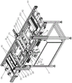
Fig. 1 is a schematic structural view of a sorting and positioning feeder of the present invention.
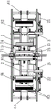
Fig. 2 is a front view of fig. 1.
Fig. 3 is a top view of fig. 1.
Fig. 4 is a side view of fig. 1.
Fig. 5 is a schematic structural view of the hidden motor cover of fig. 1.
Detailed Description
The invention is further described with reference to the following figures and examples.
As shown in fig. 1 to 5, a sorting and positioning feeder includes a frame 1, a left sorting mechanism 2, a right sorting mechanism 3, a driving mechanism 4, a left material supporting mechanism 8, a right material supporting mechanism 9, a left horizontal feeding mechanism 5, a right horizontal feeding mechanism 6, and a middle positioning discharging mechanism 7.
The left and right sorting mechanisms 2 and 3 are respectively positioned at two sides of the rack 1 and used for sorting stacked materials one by one on the horizontal feeding belts 61 of the left and right horizontal feeding mechanisms 5 and 6.
The left and right material supporting mechanisms 8 and 9 are respectively positioned at two sides of the frame 1 and used for supporting materials so as to facilitate the feeding of the horizontal feeding belts of the left and right horizontal feeding mechanisms 5 and 6.
The left and right horizontal feeding mechanisms 5 and 6 are respectively positioned at two sides of the rack 1 and used for conveying materials at two sides of the rack 1 one by one to the middle positioning discharging mechanism 7 for positioning.
And the driving mechanism 4 is used for driving the horizontal feeding belts 61 of the left and right horizontal feeding mechanisms 5 and 6 to feed materials to the middle of the rack 1.
The middle positioning discharging mechanism 7 is positioned in the middle of the rack 1 and used for positioning materials.
As a more specific technical solution of the present invention.
Left and right sorting mechanism 2, 3 all include that horizontal transfer cylinder 21, horizontal transfer seat 22, lift cylinder 23, lift seat 24 and inhale material arm 25, and horizontal transfer seat 22 horizontal slip sets up in frame 1, and horizontal transfer cylinder 21 is located frame 1 and is connected with horizontal transfer seat 22 drive, lift seat 24 oscilaltion sets up at horizontal transfer seat 22, lift cylinder 23 is located on horizontal transfer seat 22 and is connected with lift seat 24 drive, inhale material arm 25 and locate on lift seat 24 and lie in the top of horizontal feeding area 61, it is equipped with sucking disc 251 on the material arm 25 to inhale.
The driving mechanism 4 is a motor 41, the motor 41 is arranged in the middle of the rack 1, the left and right horizontal feeding mechanisms 5 and 6 respectively comprise horizontal feeding belts 61, the two horizontal feeding belts 61 are respectively rotatably arranged on the left and right sides of the rack 1, the motor 41 is in driving connection with the two horizontal feeding belts 61, and the motor 41 drives the two horizontal feeding belts 61 to rotate.
The left and right material supporting mechanisms 8 and 9 comprise a supporting plate 81 and a first supporting cylinder 82, the supporting plate 81 is arranged on the rack 1 and is positioned on the horizontal feeding belt 61, a material placing station 83 for placing the stacked materials 12 is arranged on the supporting plate 81, and the first supporting cylinder 82 is arranged on the rack 1 and is positioned beside the material placing station 83.
The middle positioning and discharging mechanism 7 comprises two end positioning cylinders 71 and 72, a positioning plate 73, a pushing positioning cylinder 74 and a positioning part 75, the positioning plate 73 is arranged in the middle of the rack 1, the two end positioning cylinders 71 and 72 are respectively arranged at the front side and the rear side of the positioning plate 73, and the pushing positioning cylinder 74 and the positioning part 75 are respectively arranged at the feeding side and the positioning side of the positioning plate 73. The positioning piece is a positioning column or a positioning block.
The discharging side of the discharging station 83 is provided with a limiting cylinder 84, the limiting cylinder 84 is positioned on the bottom surface of the supporting plate 81, and the cylinder rod of the limiting cylinder 84 extends out of the supporting plate 81.
The left and right horizontal feeding mechanisms 5 and 6 further comprise driving rollers 63 and driven rollers 64, the horizontal feeding belt 61 is arranged on the driving rollers 63 and the driven rollers 64, the driving rollers 63 and the driven rollers 64 are respectively and rotatably arranged in the middle of the rack and on one side of the rack, and the motor 41 is in driving connection with the two driving rollers 63.
A drive gear 40 is arranged on a motor shaft of the motor 41, driven gears 42 and 43 are arranged on the drive roller 63, the drive gear 40 is in chain gear transmission connection with one of the drive rollers 63, the two driven gears 42 and 43 are in meshing transmission with each other, and the motor 41 drives the two drive rollers 6342 and 43 to rotate reversely.
The frame 1 is provided with a horizontal guide rail 11 along the horizontal direction, and the horizontal transfer seat 22 is slidably arranged on the horizontal guide rail 11.
The horizontal transfer base 22 is provided with a vertical guide rail 26 in a vertical direction, and the elevating base 24 is slidably provided on the vertical guide rail 26 up and down.
A second supporting cylinder 14 is arranged beside the positioning plate 73.
The working principle of the invention is as follows:
before the material sucking device works, a worker or a mechanical arm firstly places a stack of materials 12 on the material placing stations of the left support plate and the right support plate, the position of the stack of materials 12 is limited by the limiting air cylinder 84, and when the material sucking device is used for positioning and discharging, the first supporting air cylinder 82 supports the stack of materials on the left support plate and the right support plate, so that the stack of materials is kept horizontal, and the material sucking device is convenient for a sucking disc 251 on a material sucking arm 25 to suck the materials. When the horizontal transfer device works, the horizontal transfer cylinder 21 drives the horizontal transfer seat 22, the lifting cylinder 23, the lifting seat 24 and the material suction arm 25 to move to the upper part of the stacked materials 12, then the lifting cylinder 23 drives the lifting seat 24 and the material suction arm 25 to descend, a sucker 251 on the material suction arm 25 sucks up a single material 13, the horizontal transfer cylinder 21 drives the material suction arm 25 to move, and the material suction arm 25 places the single material 13 on the horizontal feeding belt 61. After the material suction arm 25 unloads, the left and right sorting mechanisms 2 and 3 return to the original positions to suck the next piece of material. The suction arm 25 repeats this action continuously to separate the stack of materials one by one onto the horizontal feed belt 61.
The motor drives the two driving rollers 63 and 64 to rotate reversely through the driving gear 40, the chain and the driven gears 42 and 43, so that the two horizontal feeding belts 61 are driven to rotate from two sides of the rack to the middle of the rack, the two horizontal feeding belts 61 convey the single-piece materials 13 on the horizontal feeding belts to the positioning plate 73, the cylinder rods of the material pushing positioning cylinders 74 ascend to push the single-piece materials 13 to the positioning plate, the left and right sides of the single-piece materials 13 are positioned by the positioning piece 75 and the material pushing positioning cylinders 74, then the two end positioning cylinders extend out from the front side and the rear side of the single-piece materials 13, the front side and the rear side of the single-piece materials 13 are positioned by the two end positioning cylinders so as to position and discharge the single-piece materials 13, and the feeding manipulator grabs the single-piece materials 13 and conveys the single-piece materials to equipment such as a mold. When the material sucking arm is used for positioning and discharging materials, the second lifting cylinder lifts the materials on the positioning plate to keep the materials horizontal, so that the materials can be conveniently sucked by the sucking disc on the external material sucking arm.
The invention is especially suitable for sorting and positioning output of sheet materials such as metal plates and the like.
Claims (9)
1. A sorting and positioning feeder is characterized by comprising a rack (1), a driving mechanism (4), a left sorting mechanism (2), a right sorting mechanism (3), a left material supporting mechanism (8), a right material supporting mechanism (9), a left horizontal feeding mechanism (5), a right horizontal feeding mechanism (6) and a middle positioning discharging mechanism (7),
The left and right sorting mechanisms (2, 3) are respectively positioned at two sides of the rack (1) and are used for sorting stacked materials one by one on horizontal feeding belts (61) of the left and right horizontal feeding mechanisms (5, 6);
the left material supporting mechanism and the right material supporting mechanism (8, 9) are respectively positioned at two sides of the rack (1) and are used for supporting materials so as to facilitate the feeding of the horizontal feeding belts of the left horizontal feeding mechanism and the right horizontal feeding mechanism (5, 6);
the left and right horizontal feeding mechanisms (5, 6) are respectively positioned at two sides of the rack (1) and are used for conveying the materials at two sides of the rack (1) to the middle positioning discharging mechanism one by one for positioning;
the driving mechanism (4) is used for driving the horizontal feeding belts (61) of the left and right horizontal feeding mechanisms (5, 6) to feed materials to the middle of the rack (1);
the middle positioning discharging mechanism (7) is positioned in the middle of the rack (1) and is used for positioning materials;
left and right sorting mechanism (2, 3) all include that the level shifts cylinder (21), level and shift seat (22), lift cylinder (23), lift seat (24) and inhale material arm (25), and level shifts seat (22) horizontal slip and sets up in frame (1), and level shifts cylinder (21) and locate frame (1) and with level shift seat (22) drive connection, lift seat (24) oscilaltion setting is at level and shifts seat (22), lift cylinder (23) are located level and are shifted seat (22) and be connected with lift seat (24) drive, inhale material arm (25) locate on lift seat (24) and be located the top of horizontal feeding area (61), it is equipped with sucking disc (251) on material arm (25).
2. The sorting and positioning feeder according to claim 1, wherein the driving mechanism (4) is a motor (41), the motor (41) is disposed in the middle of the frame (1), the left and right horizontal feeding mechanisms (5, 6) each include a horizontal feeding belt (61), the two horizontal feeding belts (61) are rotatably disposed on the left and right sides of the frame (1), and the motor (41) is drivingly connected to the two horizontal feeding belts (61).
3. The sorting and positioning feeder according to claim 2, wherein the left and right material supporting mechanisms (8, 9) comprise a supporting plate (81) and a first supporting cylinder (82), the supporting plate (81) is arranged on the frame (1) and located on the horizontal feeding belt (61), a material placing station (83) for placing stacked materials is arranged on the supporting plate (81), and the first supporting cylinder (82) is arranged on the frame (1) and located beside the material placing station (83).
4. The sorting and positioning feeder according to claim 3, wherein the middle positioning discharging mechanism (7) comprises two end positioning cylinders (71, 72), a positioning plate (73), a pushing positioning cylinder (74) and a positioning member (75), the positioning plate (73) is arranged in the middle of the rack (1), the two end positioning cylinders (71, 72) are respectively arranged at the front side and the rear side of the positioning plate (73), and the pushing positioning cylinder (74) and the positioning member (75) are respectively arranged at the feeding side and the positioning side of the positioning plate (73).
5. The sorting and positioning feeder of claim 4, wherein a limiting cylinder (84) is arranged on the discharging side of the discharging station (83), the limiting cylinder (84) is positioned on the bottom surface of the supporting plate (81), and a cylinder rod of the limiting cylinder (84) extends out of the supporting plate (81).
6. The sorting and positioning feeder of claim 5, wherein the left and right horizontal feeding mechanisms (5, 6) further comprise a driving roller (63) and a driven roller (64), the horizontal feeding belt (61) is arranged on the driving roller (63) and the driven roller (64), the driving roller (63) and the driven roller (64) are respectively and rotatably arranged in the middle of the frame (1) and on one side of the frame, and the motor (41) is in driving connection with the two driving rollers (63).
7. The sorting and positioning feeder of claim 6, wherein a driving gear (40) is arranged on a motor shaft of the motor (41), driven gears (42, 43) are arranged on the driving roller, the driving gear (40) is in transmission connection with one of the driving roller chain gears, and the two driven gears (42, 43) are in meshing transmission with each other.
8. The sorting and positioning feeder of claim 7, wherein the frame 1 is provided with a horizontal guide rail (11) along the horizontal direction, and the horizontal transfer seat (22) is slidably arranged on the horizontal guide rail (11).
9. The sorting and positioning feeder of claim 8, wherein a second supporting cylinder (14) is arranged beside the positioning plate (73).
Priority Applications (1)
| Application Number | Priority Date | Filing Date | Title |
|---|---|---|---|
| CN201710029509.2A CN106586585B (en) | 2017-01-16 | 2017-01-16 | Sorting and positioning feeder |
Applications Claiming Priority (1)
| Application Number | Priority Date | Filing Date | Title |
|---|---|---|---|
| CN201710029509.2A CN106586585B (en) | 2017-01-16 | 2017-01-16 | Sorting and positioning feeder |
Publications (2)
| Publication Number | Publication Date |
|---|---|
| CN106586585A CN106586585A (en) | 2017-04-26 |
| CN106586585B true CN106586585B (en) | 2022-07-12 |
Family
ID=58585443
Family Applications (1)
| Application Number | Title | Priority Date | Filing Date |
|---|---|---|---|
| CN201710029509.2A Active CN106586585B (en) | 2017-01-16 | 2017-01-16 | Sorting and positioning feeder |
Country Status (1)
| Country | Link |
|---|---|
| CN (1) | CN106586585B (en) |
Families Citing this family (3)
| Publication number | Priority date | Publication date | Assignee | Title |
|---|---|---|---|---|
| CN107472895A (en) * | 2017-09-04 | 2017-12-15 | 广东利迅达机器人系统股份有限公司 | A kind of flow channel type is layered upper trigger |
| CN109693947A (en) * | 2017-10-24 | 2019-04-30 | 泉州向日葵卫生用品有限公司 | A kind of box stacker of compound core body |
| CN113714412A (en) * | 2021-08-26 | 2021-11-30 | 广东捷瞬机器人有限公司 | Sheet feeding device of automatic sheet blanking and punching production line |
Citations (4)
| Publication number | Priority date | Publication date | Assignee | Title |
|---|---|---|---|---|
| JPH02204214A (en) * | 1989-01-31 | 1990-08-14 | Natl House Ind Co Ltd | Face material handling installation |
| CN105645088A (en) * | 2016-03-16 | 2016-06-08 | 广东富山玻璃机械有限公司 | Automatic rearview mirror feeder |
| CN105775769A (en) * | 2016-04-21 | 2016-07-20 | 佛山市顺德区凯硕精密模具自动化科技有限公司 | Single-station servo sheet machine |
| CN206375435U (en) * | 2017-01-16 | 2017-08-04 | 广东捷瞬机器人有限公司 | Sorting positioning feeder |
Family Cites Families (10)
| Publication number | Priority date | Publication date | Assignee | Title |
|---|---|---|---|---|
| DD149751A3 (en) * | 1979-03-06 | 1981-07-29 | Schmidt Gerhard R | WERKSTUECKTRANSPORTEINRICHTUNG |
| DE3412575C2 (en) * | 1984-04-04 | 1987-04-16 | Rudolf Geiger Maschinenbau, 8553 Ebermannstadt | Conveyor device |
| DE10320482A1 (en) * | 2002-05-31 | 2003-12-11 | Heidelberger Druckmasch Ag | Device for transporting and rotating of stacks of sheet-form printed material has gear for rotation unit to convert rotational movement of lever into rotational movement of gripper, and with transmission ratio of 2 to 1 |
| US8807320B2 (en) * | 2012-06-21 | 2014-08-19 | Mantissa Corporation | Independent discharge sorting conveyor |
| JP5999508B2 (en) * | 2013-03-15 | 2016-09-28 | 株式会社ダイフク | Carrying device for box for conveying goods |
| DE102013103687B3 (en) * | 2013-04-12 | 2014-05-22 | Schott Ag | Apparatus and method for conveying a glass tube or glass rod strand with a cross section deviating from a circular shape and use thereof |
| CN203946594U (en) * | 2014-03-13 | 2014-11-19 | 台州华曙机械有限公司 | The packing feeder of injecting products |
| CN104942450B (en) * | 2015-06-30 | 2016-09-14 | 广州锐速智能科技股份有限公司 | Double sole laser cutting machine and laser cutting method |
| CN105750438A (en) * | 2016-04-21 | 2016-07-13 | 佛山市顺德区凯硕精密模具自动化科技有限公司 | Three-dimensional punching mechanical arm |
| CN105855901B (en) * | 2016-06-22 | 2019-02-22 | 佛山市顺德区凯硕精密模具自动化科技有限公司 | The stamping stacking intelligent robot production line of electric cooker |
-
2017
- 2017-01-16 CN CN201710029509.2A patent/CN106586585B/en active Active
Patent Citations (4)
| Publication number | Priority date | Publication date | Assignee | Title |
|---|---|---|---|---|
| JPH02204214A (en) * | 1989-01-31 | 1990-08-14 | Natl House Ind Co Ltd | Face material handling installation |
| CN105645088A (en) * | 2016-03-16 | 2016-06-08 | 广东富山玻璃机械有限公司 | Automatic rearview mirror feeder |
| CN105775769A (en) * | 2016-04-21 | 2016-07-20 | 佛山市顺德区凯硕精密模具自动化科技有限公司 | Single-station servo sheet machine |
| CN206375435U (en) * | 2017-01-16 | 2017-08-04 | 广东捷瞬机器人有限公司 | Sorting positioning feeder |
Also Published As
| Publication number | Publication date |
|---|---|
| CN106586585A (en) | 2017-04-26 |
Similar Documents
| Publication | Publication Date | Title |
|---|---|---|
| CN108580731B (en) | Stamping device capable of automatically feeding and discharging | |
| CN108820872B (en) | Feeding mechanism | |
| CN106829500B (en) | Servo oil-applying sheet material rotary positioning machine | |
| CN110695233B (en) | Middle layer punching production line of electric cooker | |
| CN111496570B (en) | Automatic cutting system for plates | |
| CN211282797U (en) | New forms of energy battery piece assembly mechanism | |
| CN106586585B (en) | Sorting and positioning feeder | |
| CN215433736U (en) | Battery piece suction mechanism, battery piece carrying device and series welding machine | |
| CN211003521U (en) | Automatic feeding mechanism of punch press | |
| CN205187345U (en) | Vacuum suction board machine | |
| CN105347025A (en) | Vacuum board loader | |
| CN114354645A (en) | Automatic leveling and detecting equipment for backlight source shell | |
| CN111906202A (en) | Full-automatic aluminum plate profiling production line | |
| CN106629063B (en) | Automatic chip feeding and powder cleaning device and working method thereof | |
| CN211619318U (en) | Automatic loading and unloading device | |
| CN203245660U (en) | Sheet conveying, loading and unloading system and laser cutting machine processing production line with same | |
| CN208712709U (en) | A kind of sheeting feed device | |
| CN207224131U (en) | One kind cuts roller shear sawing sheet system automatically | |
| CN211614087U (en) | Middle-layer stamping production line of electric cooker | |
| CN112404251A (en) | Automatic robot feeding and discharging stamping production line with double sliding rails | |
| CN109093022B (en) | Automatic feeding and discharging unit of large press | |
| CN206375435U (en) | Sorting positioning feeder | |
| JP5188460B2 (en) | Substrate take-out mechanism and substrate supply apparatus provided with the same | |
| CN221113041U (en) | Automatic paper feeding equipment | |
| CN214290367U (en) | Automatic robot feeding and discharging stamping production line with double sliding rails |
Legal Events
| Date | Code | Title | Description |
|---|---|---|---|
| PB01 | Publication | ||
| PB01 | Publication | ||
| SE01 | Entry into force of request for substantive examination | ||
| SE01 | Entry into force of request for substantive examination | ||
| GR01 | Patent grant | ||
| GR01 | Patent grant |