CN1056336C - Multi-stage automatic press and assembly machine - Google Patents
Multi-stage automatic press and assembly machine Download PDFInfo
- Publication number
- CN1056336C CN1056336C CN94107501A CN94107501A CN1056336C CN 1056336 C CN1056336 C CN 1056336C CN 94107501 A CN94107501 A CN 94107501A CN 94107501 A CN94107501 A CN 94107501A CN 1056336 C CN1056336 C CN 1056336C
- Authority
- CN
- China
- Prior art keywords
- cylinder
- workpiece
- press
- circuit
- assembly machine
- Prior art date
- Legal status (The legal status is an assumption and is not a legal conclusion. Google has not performed a legal analysis and makes no representation as to the accuracy of the status listed.)
- Expired - Fee Related
Links
Images


Classifications
-
- B—PERFORMING OPERATIONS; TRANSPORTING
- B23—MACHINE TOOLS; METAL-WORKING NOT OTHERWISE PROVIDED FOR
- B23P—METAL-WORKING NOT OTHERWISE PROVIDED FOR; COMBINED OPERATIONS; UNIVERSAL MACHINE TOOLS
- B23P19/00—Machines for simply fitting together or separating metal parts or objects, or metal and non-metal parts, whether or not involving some deformation; Tools or devices therefor so far as not provided for in other classes
- B23P19/001—Article feeders for assembling machines
- B23P19/007—Picking-up and placing mechanisms
-
- B—PERFORMING OPERATIONS; TRANSPORTING
- B21—MECHANICAL METAL-WORKING WITHOUT ESSENTIALLY REMOVING MATERIAL; PUNCHING METAL
- B21K—MAKING FORGED OR PRESSED METAL PRODUCTS, e.g. HORSE-SHOES, RIVETS, BOLTS OR WHEELS
- B21K27/00—Handling devices, e.g. for feeding, aligning, discharging, Cutting-off means; Arrangement thereof
- B21K27/02—Feeding devices for rods, wire, or strips
- B21K27/04—Feeding devices for rods, wire, or strips allowing successive working steps
-
- B—PERFORMING OPERATIONS; TRANSPORTING
- B23—MACHINE TOOLS; METAL-WORKING NOT OTHERWISE PROVIDED FOR
- B23P—METAL-WORKING NOT OTHERWISE PROVIDED FOR; COMBINED OPERATIONS; UNIVERSAL MACHINE TOOLS
- B23P19/00—Machines for simply fitting together or separating metal parts or objects, or metal and non-metal parts, whether or not involving some deformation; Tools or devices therefor so far as not provided for in other classes
- B23P19/02—Machines for simply fitting together or separating metal parts or objects, or metal and non-metal parts, whether or not involving some deformation; Tools or devices therefor so far as not provided for in other classes for connecting objects by press fit or for detaching same
-
- Y—GENERAL TAGGING OF NEW TECHNOLOGICAL DEVELOPMENTS; GENERAL TAGGING OF CROSS-SECTIONAL TECHNOLOGIES SPANNING OVER SEVERAL SECTIONS OF THE IPC; TECHNICAL SUBJECTS COVERED BY FORMER USPC CROSS-REFERENCE ART COLLECTIONS [XRACs] AND DIGESTS
- Y10—TECHNICAL SUBJECTS COVERED BY FORMER USPC
- Y10T—TECHNICAL SUBJECTS COVERED BY FORMER US CLASSIFICATION
- Y10T29/00—Metal working
- Y10T29/51—Plural diverse manufacturing apparatus including means for metal shaping or assembling
- Y10T29/5136—Separate tool stations for selective or successive operation on work
- Y10T29/5137—Separate tool stations for selective or successive operation on work including assembling or disassembling station
-
- Y—GENERAL TAGGING OF NEW TECHNOLOGICAL DEVELOPMENTS; GENERAL TAGGING OF CROSS-SECTIONAL TECHNOLOGIES SPANNING OVER SEVERAL SECTIONS OF THE IPC; TECHNICAL SUBJECTS COVERED BY FORMER USPC CROSS-REFERENCE ART COLLECTIONS [XRACs] AND DIGESTS
- Y10—TECHNICAL SUBJECTS COVERED BY FORMER USPC
- Y10T—TECHNICAL SUBJECTS COVERED BY FORMER US CLASSIFICATION
- Y10T29/00—Metal working
- Y10T29/53—Means to assemble or disassemble
- Y10T29/53026—Means to assemble or disassemble with randomly actuated stopping or disabling means
-
- Y—GENERAL TAGGING OF NEW TECHNOLOGICAL DEVELOPMENTS; GENERAL TAGGING OF CROSS-SECTIONAL TECHNOLOGIES SPANNING OVER SEVERAL SECTIONS OF THE IPC; TECHNICAL SUBJECTS COVERED BY FORMER USPC CROSS-REFERENCE ART COLLECTIONS [XRACs] AND DIGESTS
- Y10—TECHNICAL SUBJECTS COVERED BY FORMER USPC
- Y10T—TECHNICAL SUBJECTS COVERED BY FORMER US CLASSIFICATION
- Y10T29/00—Metal working
- Y10T29/53—Means to assemble or disassemble
- Y10T29/53313—Means to interrelatedly feed plural work parts from plural sources without manual intervention
- Y10T29/53383—Means to interrelatedly feed plural work parts from plural sources without manual intervention and means to fasten work parts together
- Y10T29/53387—Means to interrelatedly feed plural work parts from plural sources without manual intervention and means to fasten work parts together by deforming
-
- Y—GENERAL TAGGING OF NEW TECHNOLOGICAL DEVELOPMENTS; GENERAL TAGGING OF CROSS-SECTIONAL TECHNOLOGIES SPANNING OVER SEVERAL SECTIONS OF THE IPC; TECHNICAL SUBJECTS COVERED BY FORMER USPC CROSS-REFERENCE ART COLLECTIONS [XRACs] AND DIGESTS
- Y10—TECHNICAL SUBJECTS COVERED BY FORMER USPC
- Y10T—TECHNICAL SUBJECTS COVERED BY FORMER US CLASSIFICATION
- Y10T29/00—Metal working
- Y10T29/53—Means to assemble or disassemble
- Y10T29/53478—Means to assemble or disassemble with magazine supply
- Y10T29/53522—Means to fasten by deforming
Abstract
A press and assembly machine has a die set which has several guide posts securely mounted on a base plate, and a oil (gas) cylinder plate securely mounted on top portions of the guide posts, and a movable plate slidably mounted on the guide posts. A cylinder is mounted on the oil (gas) cylinder plate. A piston rod of the cylinder is connected to the movable plate. A pick-and-place device is mounted on the base plate. The pick-and-place device comprises a pair of guide rails, several sliding members, a connecting member, a reciprocating cylinder and a plurality of gripping actuators. Furthermore, a parts-feeder is provided for feeding works one by one to the pick-and-place device and a sequence controller is provided for sequentially operating the machine for progressively pressing and assembling works.
Description
The present invention relates to a continuous automatic press and assembly machine.Machine is provided with one and is used for sending to intermittently a workpiece and takes out the discharging device of choosing that has processed workpiece, and is operated automatically by a sequence controller.
The punching machine that has progressive die is generally used for live-roll feeder from the band production work.Workpiece is generally by a manipulator break transfer, so press structurally more complicated and costliness.
An object of the present invention is to provide a continuous multi-stage stamping machine, its employing one has executing agency and has one intermittently chooses the die set of discharging device, thereby can simplify the structure of machine, reduces its size and weight, and is made cheaply.
Press according to the present invention is made up of following some parts: based on one pair of set of molds that has a pneumatic or hydraulic cylinder, one is used for sending to intermittently a workpiece to stamping machine and take out a discharging device of choosing that has completed workpiece, and a read-only sequence controller that is used for operating automatically press.
According to the present invention, provide a set of molds to a press and assembly machine, set of molds is equipped with a base plate, and some are loaded on the upright guide pillar on the base plate, and one is installed in level oil (gas) the cylinder plate on these upright guide pillar tops, and one is assemblied in the moving plate on these leading posts slidably.
Press and assembly machine contains oil (gas) cylinder that vertically is contained on oil (gas) the cylinder plate, and pressure cylinder has a piston rod to be connected on the moving plate.Be equipped with one on the base plate and choose discharging device.
Choose discharging device and contain a pair of guide rail that is contained in upper and lower mould two offsides of base plate, several subtend sliding parts that are contained in slidably on the guide rail, one connects the connector of sliding part, one is used for back and forth driving the linear actuator that these are connected sliding part, and a plurality of promptly executing agency that is arranged on these subtend sliding parts.
Promptly executing agency has relative promptly cylinder, is used for clamping the relative promptly pawl of a workpiece by the piston rod operation of respective cylinder.
Inlet side at stamping machine is equipped with a part feeding device, is used for one by one workpiece being delivered to choosing discharging device.
One sequence controller is used for operating press and chooses discharging device, carries out sending constantly into of workpiece.
Being provided with a lifting device is used for promoting and chooses discharging device.Lifting device has some and is contained in lift cylinder on the base plate, and the piston rod on each lift cylinder is connected in and is used for lift rail on the corresponding guide rail.
Sequence controller contains a main circuit and the parallel circuit that the command signal of being sent in a predetermined circulation timei by main circuit is handled.Be longer than parallel circuit the circulation timei of main circuit so that the control latter.Be provided with a sensor in the outlet of machine and be used at the end detecting the discharge of workpiece, and produce a discharging signal to parallel circuit in each circulation.In normal operation, parallel circuit is restarted by the command signal of main circuit.When producing when unusual, sensor no longer sends the discharging signal, and one stop control circuit and send stop signal and stop main circuit and parallel circuit.Machine stops on the top dead-centre.
The present invention and then the punching press assembly line that provides a multistage press and assembly machine that contains multiply-computer series connection to form.
The multistage continuous cold forging press that can equip according to the present invention, a multistage continuous motor-driven stamping machine also can be equipped a punching press assembly line.
Each cold forging and punching machine contain a part feed arrangement that is located at its porch, one has and is used for the set of molds of choosing discharging device of break transfer workpiece, one is fixed on base plate and on the press support is fixed on moving plate on the press slide plate, one is arranged on sensor on the blow tank is used for finished product detection and discharge and are contained in the operation that sequence controller on the press is used for controlling press.
The punching press assembly line is made up of at the multistage press and assembly machine that its blow tank exit is connected in series with cold forging machine a multistage continuous cold forging press and Duo Tai.
From following detailed description, with reference to accompanying drawing, these and some other target and characteristics can clearer understanding of the present invention.
Fig. 1 be one according to the present invention the side view of press;
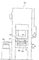
Fig. 2 is the front front view of press;
Fig. 3 is a plane of choosing discharging device;
Fig. 4 partly chooses the side view of discharging device for expression;
Fig. 5 chooses discharging device another part side view for expression;
Fig. 6 represents the transparent process sheet of a read-only sequence controller;
Fig. 7 represents with opaque adhesive tape attached to the timetable on the transparent process sheet;
Fig. 8 is an expression one EPROM
*The perspective view of functional generator;
Fig. 9 is the front view of an expression second embodiment of the invention;
Figure 10 is that an expression sends a workpiece to the schematic diagram of choosing discharging device to;
Figure 11 is the cutaway view of a thermal actuator;
Figure 12 is the front view of third embodiment of the invention;
Figure 13 is the front view of a read-only sequence controller;
Figure 14 is the side view of read-only sequence controller;
Figure 15 represents the line map of a sequence controller.
Referring to Fig. 1 and 2, be fixed with two vertical guide pillars 1 on the base plate 2, guide pillar is fixed on the workbench 2a.Being connected in each guide pillar 1 slippingly by guide pin bushing 3 will move plate 4 and be contained in slidably on the guide pillar 1.So the set of molds that a tool is commonly used just is made up of 1,2,3,4 four parts.Level oil (gas) cylinder plate 7 is fixed with bolt 8 in top at each guide pillar 1.Vertically be contained on the plate 7 and be fixed thereon such as a hydraulic cylinder 5 of oil cylinder or cylinder with screw 6.The piston rod 9 of cylinder 5 has screw thread.By this screw thread being combined with screw thread on the moving plate and piston rod 9 being fixed on the moving plate 4 with locknut 10 lockings.Counterdie 17 is housed on base plate 2, and patrix 17a then is fixed on the downside of moving plate 4.So, just can between mould 17 and 17a, carry out stamping press by operation cylinder 5.The one read-only sequence controller R that is got up by lid 14 covers is connected on the cylinder plate 7 by an electric wire connecting junction 13, so that operate press automatically.
Being contained on the base plate 2 is that a continuous multi-stage is chosen discharging device 11, is used for delivering to workpiece A and B on the mould 17 and removing manufactured workpiece.
Choose Fig. 3 and 4 of discharging device 11 referring to expression, the relative both sides of the following punch die 17 on base plate 2 are equipped with a pair of guide rail 16 that slides in parallel to each other.A pair of slide block 15 at a distance of a preset distance is housed on each guide rail 16 slippingly.Every pair of slide block 15 is fixed a L shaped support plate 19.On support plate 19, be provided with two pairs of promptly executing agencies.Each is firmly grasped executing agency and is made up of the relative pneumatic linear actuator 18 and the 18a that are fixed in two relative support plates 19. Cylinder 18 and 18a are with predetermined equidistantly being positioned at respectively on primary importance P1 and the second place P2.The end of two support plates 19 is linked to each other by a plate 20.
Relative promptly pawl 21 usefulness nuts 22 are fixed on the piston rod 18b of each cylinder of firmly grasping executing agency 18 and 18a and are used for firmly grasping workpiece A.
Fix a support plate 20a in two ends of sliding guide rail 16.One cylinder 23 is fixed on that support plate 20a goes up and piston rod 24 is connected on the connecting plate 20.So, cylinder 18 and 18a on the support plate 19 are moved back and forth between position P1, P2 and P3 by the work of inciting somebody to action the cylinder 23 that tell in detail afterwards.
As shown in Figure 4, slide guide rail 16 below be provided with a pair of lifting device of choosing discharging device 11 that is used for promoting.Each lifting device has a guide pillar 25 that is fixed on the guide rail 16, and guide pillar then is combined in one slippingly and crosses interference fit and be pressed in the guide pin bushing 26 in the base plate 2.Correspond to each guide pillar 25, fix a vertical cylinder 27 on the bottom surface of base plate 2, the piston rod 28 of cylinder 27 then is connected on the guide pillar 25.So,, slide guide rail 16 and move up and down by the effect of these cylinders 27.
Referring to Fig. 3 and 5, be provided with a part feeder 29 and be used for making numerous workpiece B automatically to be arranged in rows.On a fixed head 30 that is packed on the base plate 2, be fixed with a pair of vertical cylinder 31.One slides guide rail 16a is fixed on the piston rod 32 of cylinder 31 with screw 37.Slide on the guide rail 16a a pair of slide block 15a can be housed glidingly.One support plate 34 is fixed on the slide block 15a.By a plate 3 5b one horizontal air cylinder 35 is linked to each other with support plate 34, and the piston rod 36 of cylinder 35 by a plate 36b with slide guide rail 16a and link to each other.Fix a horizontal air cylinder 38 that has a chuck 37 on the bottom surface of support plate 34.
Under normal circumstances chuck 37 is open.According to the operation of cylinder 38, chuck draws in to firmly grasp workpiece B and open once more to discharge workpiece.
The operation in tandem of press hereinafter will be described.
Workpiece A is a heat conduction cylinder, is used for the thermal actuator of the cured ball thermostat of car engine cooling system.
Fig. 9 represents that one is used for producing workpiece A according to the present invention, and energy is 160 tons a cold forging mo(u)ldenpress.Press 123 has a part feeder 124 and one pair to be provided with the set of molds 125 of choosing discharging device according to of the present invention, the base plate 2A of set of molds 125 is contained in guide pillar 1A slidably and goes up and be fixed on the support 126, and a moving plate 4A of set of molds then is fixed on the slide plate 127 of press.Blow tank 42a is provided with a sensor 40, and loads onto sequence controller 12 on lathe.So just formed a continuous multi-stage cold forging press.
Machine by three process sequence ground work, is suppressed the 15mm external diameter with Automatic Control, and the long copper bar material of 14mm is produced cylindrical work A.
As shown in figure 10, workpiece A delivers to a part feeder 29a (Fig. 3) by the hopper 42a of cold forging mo(u)ldenpress and is arranged in rows in the formed guide groove 42 above the guide plate 30a on being installed in base plate 2.The head of workpiece A is by fixing on primary importance P1 place.
Referring to Fig. 3, slide guide rail 16 and descend by the working face of cylinder 27 cylinder 18 and 18a are descended, and the piston rod 18b of cylinder 18 and 18a travels forward, so that some corresponding pawls 21 close and disturb, in firmly grasping guide groove 42, primary importance P1 place takes the lead workpiece A.Then, slide that guide rail 16 moves upward and cylinder 23 work, the support plate 19 on the slide block 15 is moved horizontally along guide rail 16.So the cylinder 18 and the 18a at primary importance P1 place move to second place P2, and the cylinder 18 at second place P2 place and 18a move to the 3rd position P3.Slide guide rail 16 and descend once more, workpiece A engages with counterdie 17 on the P2 position, and the piston rod 18b of cylinder 18 and 18a recession makes pawl 21 break away from workpiece A then.After this, cylinder 18 and 18a rise and get back to primary importance P1 and second place P2 respectively.
In cylinder assembly by following be provided with automatically fixed (in) concentric mechanism.
At the internal diameter of each cylinder 18a of the lathe one side cylinder 18 greater than opposite side, each cylinder 18a has bigger air pressure than cylinder 18 like this.So when if the pawl of cylinder 18 21 promotes workpiece A, the workpiece A that combines with the pawl 21 of cylinder 18a will not move.That is to say that the pawl 21 of cylinder 18a is only depended in the position of workpiece A.So workpiece with respect to mould 17 fixed (in) heart is just definite exactly by cylinder 18a.Its result has prevented to damage owing to the mould that cause the off-centre location of workpiece.
On the other hand, sliding guide rail 16a with cylinder 31 declines falls the cylinder 38 on the support plate 34.Chuck 37 is connected on the piston rod of cylinder 38, promptly takes the lead workpiece B, and guide rail 16a is up then.Support plate 34 on the slide block 15a is moved horizontally to mould 17 by the work of cylinder 35 along guide rail 16a.The guide rail 16a of P2 on the throne place descends, and chuck 37 makes workpiece B insert workpiece A with opening.After this, support plate 34 is back to original position.
Then, as shown in Figure 2, moving plate 4 is descended by the operation of hydraulic cylinder 5, with upper and lower mould 17 and 17a workpiece B is depressed into workpiece A.Thereby workpiece B is crossed to be force-fitted in the workpiece A.Plate 4 is up then.
Subsequently, sliding guide rail 16 descends.The workpiece that cylinder 18 on the second place P2 and the pawl of 18a 21 have promptly pressed, and the pawl of the cylinder 18 at primary importance P1 place and 18a is firmly grasped next workpiece A.Support plate 19 rises and moves to right in Fig. 3, makes the cylinder 18 at second place P2 place and 18a move to the 3rd position P3.These cylinders descend then, and pawl returns to be removed.So the workpiece that has suppressed breaks away from pawl 21, is discharged in the groove.Meanwhile, the cylinder 18 and the 18a at primary importance P1 place move to second place P2, by pawl 21 next workpiece A are combined with mould 17 there.
Next workpiece B is incorporated in the workpiece A and by mould 17 and 17a with above-mentioned the same manner and presses work.
Figure 11 represents one to be used in the cured ball thermostat of car engine cooling system, contains the thermal actuator of workpiece A and B.
Be listed as by multistage press and assembly machine group of the present invention many, can form a continuous assembly line that is used to make thermostat.
Figure 12 represents a punching machine as third embodiment of the invention.Press 128 has a part feeder 124a and is provided with the set of molds 129 of choosing discharging device according to of the present invention its import department and one pair.The moving plate 4B that the base plate 2B of set of molds 129 is fixed in support 130, two set of molds then is contained in several guide pillar 1B slidably and goes up and be fixed on the press slide plate 131.Sensor 40 is arranged on the last sequence controller 12 of hopper 42a and then is contained in above the machine.Just formed a continuous motor-driven press and assembly machine thus.
The said sequence operation is by read-only sequence controller 12 controls.
With reference to Figure 13 and 14, read-only sequence controller 12 comprises read clock control module 43 and who has power supply and is contained in the output relay unit of reading on the clock control module 43 44.
Reading on the clock control module 43, be provided with a power switch 53, fuse 54, light emitting diode lamp 55, light emitting diode abnormal conditions display starting switch 57, reset switch 58, some lead-in clamps 59, one be used for main circuit A preset that code-bar switch 60 and is used for parallel circuit B preset code-bar switch 61.Be used for controlling the procedure stores of said sequence operation in EPROM 48.
Fig. 6 represents that is used for a stored program transparent process sheet 120.Slice is provided with predetermined project, for example some panel data line 120a that stamp with opaque ink.As shown in Figure 7, a program that comprises eight joint timetables upward forms by opaque adhesive tape 121 being sticked on these panel data lines 120a.
For the change timetable, with the opaque adhesive tape 121 that lancinates, like this, timetable can be changed at an easy rate.
Fig. 8 represents that a program that will be stored in the slice 120 deposits into the EPROM functional generator 122 in the EPROM48.Slice 120 is inserted cracking in 41 of functional generators 122, and from the (not shown) that cracks of its offside, extract out.So the data on the slice 120 just are stored in EPROM48 and have suffered.EPROM48 can be fixed on the read-only sequence controller 12 with pulling down.
With reference to Figure 15 of expression one controller circuitry, circuit comprises among main circuit A and Figure 15 with the separated parallel circuit B of one one line.The circulation timei of main circuit A is with presetting code-bar switch 60 set to 2.5 second.The circulation timei of parallel circuit B is by code-bar switch 61 set to 1.5 of presetting second.When pressing power switch 53 and reset switch 58, obtain power source voltage Vcc by a switching regulator 62, so a system power supply voltage is applied on the initial reset circuit 63 output that makes phase inverter 64 produce a level 17.Output turn to 0 level by phase inverter 65, and each R-S (reset-set) latch of first to the 6th trigger is resetted or set.
When first trigger 66 resetted, a transistor 67 turn-offed, and made the output of an inverter 69 turn to 1 by anti-circuit C and the Schmidt circuit 68 of trembling.The output of the phase inverter 70 of main circuit A becomes " 0 ", is applied to a CI input that can preset down-counter 71, makes can preset down-counter 71,72 and become the count enable state.
By 74 pairs second trigger 73 set of dual input NOT-AND gate.One single-shot pulse " 0 " appears at the output of single-shot pulse generating circuit 75.
When by 77 pairs the 3rd trigger 76 set of dual input NOT-AND gate, export the CE input that is applied to EPROM48 by socket 51, make EPROM stop to produce data for one 1.
When resetting by 79 pairs the 4th triggers 78 of dual input NOT-AND gate, a level is that 0 output makes the RESET input R that is applied to clock circuit 80, and it is quit work.0 level and then be applied to the input PE end that can preset down-counter 82 and 83 by dual input NOT-AND gate 81 is inserted in counter 83 and 82 in advance with the number " 15 " that will preset code-bar switch 61 respectively.
When resetting by 85 pairs the 5th triggers 84 of dual input NOT-AND gate, the output of-0 level is applied to a dual input NOT-AND gate 86 as abnormality signal out gate.
When making by phase inverter 88 that the 6th trigger 87 resets in the main circuit A, produce the output of-0 level, and the output of-1 level is applied to the input point PE that can put down-counter 71 and 72 by a dual input NOT-AND gate 89, and the number " 25 " that presets code-bar switch 60 is inserted in counter 72 and 71 in advance.
0 output of the 6th trigger 87 further is applied to the 7th trigger 91 by a dual input NOT-AND gate 90, and be applied to a clock circuit 94 that a crystal oscillator is housed by phase inverter 92 and dual input NOR gate 93, make it stop to produce clock pulses.
When pressing the firing switch 57 of main circuit A, make 87 set of the 6th trigger by vibration prevention circuit C and phase inverter 95.So one 1 level output just is applied to clock circuit 94 by phase inverter 92 and a dual input NOR gate 93.
The clock pulse generator 94 that is provided with a crystal oscillator is output as 10Hz, as clock pulses.Clock pulses is applied to respectively on the clock line C that can put down-counter 71 and 72.
On the other hand, when phase inverter 97 produces " 1 " output, one " 0 " of dual input NOT-AND gate 98 outputs.So apply " a 1 " pulse to the PE of each presettable counter end by dual input NOT-AND gate 89.At this moment, presetting " 25 " in the code-bar switch 60 is preset in once more and can presets in down-counter 71 and 72.
" 0 " output of door 98 further is applied to the set end points of the 7th trigger 91 by phase inverter 99.One 1 level command signal is applied to parallel circuit B from the 7th trigger 91 by transistor 100 and phase inverter 101.Immediately, the output of phase inverter 97 resets the 7th trigger 91 by 90 upsets of a dual input NOT-AND gate for " 0 ".Thereby produce a command signal.Command signal is applied to the end points R that resets of second trigger 73 of parallel circuit B per 2.5 seconds continuously.
When second trigger 73 resetted, one 0 level output was applied to single-shot pulse generating circuit 75.A single-shot pulse " 1 " appears at the output of circuit 75.The set end points S that this single-shot pulse " 1 " is applied to the 4th trigger 78 is to produce an output 1 that is applied to clock circuit 80.It is output as 1000Hz, as clock pulses.Clock pulses is applied to respectively on the clock line C that can preset down-counter 82 and 83.
When the output of the 4th trigger 78 " 1 " was applied to one 3 input NOT-AND gate 102, its three inputs transferred " 1 " to.Door 102 produces the output of one 0 level, is applied to the CI end points that can preset down-counter 82.
Each clock pulses is applied to presettable counter, and the number that presets there just reduces 1.When to can put counter and applied 15 clock pulses the time, two inputs of dual input NOR gate 103 all transfer " 0 " to.So dual input NOR gate 103 produces a readout clock pulse.
The single-shot pulse " 1 " of single-shot pulse generation circuit 75 further is applied to the reset terminal of the 3rd trigger 76, and its output 0 is applied to the CE end of EPROM48 by socket 51, EPROM then set to output state.
On the other hand, when the output of dual input NOR gate 13 transfers " 1 " to, 105 outputs one " 0 " of dual input NOT-AND gate, and phase inverter 104 produces output " 1 ".Like this, but the PE of each presetting bit counter is held,, applied a pulse " 1 " by dual input NOT-AND gate 81.At this moment, the number of initialization code-bar switch 61 " 15 " is predisposed once more and can presets in down-counter 82 and 83.
Like this, whenever applied 15 clock pulses to presettable counter 82 and 83, by door 105 a readout clock pulse takes place.The readout clock pulse is applied on the clock line C of binary counter 106.Therefore, binary counter 106 produces output by address wire Q1 to Q7, so that by socket 51 these outputs is applied on the address among the EPROM48.
On the other hand, EPROM48 responds these address signals and produces a data-signal, makes the work of executing agency separately of those cylinders of press by relay unit 44.
The time of a circulation is by the number decision of pulse readout time.Will be explained in the work under the situation of 100 pulses readout time in the circulation below.
For whenever 100 readout clock pulses produce a loop termination signal, select the input of Q3, the Q6 of binary counter 106 and Q7 address wire as 3 input NOT-AND gates 107.Because the binary number of " 100 " is 1100100, when the 100th readout clock pulse imposed on binary counter 106, output on address wire Q3, Q6 and the Q7 transfers " 1 " to, and 3 input NOT-AND gates 107 produce one one loop termination signal " 0 ".
When finishing a circulation time, the 3rd trigger 76 is set by dual input NOT-AND gate 77, thereby holds the generation that stops that applying 1 to export to the CE of EPROM48.Make 84 set of the 5th trigger by phase inverter 108.One first input of the abnormality signal out gate of dual input NOT-AND gate 86 becomes " 1 ".One loop termination signal 0 is applied to 3 input NOT-AND gates 103, thereby makes a level"1" signal impose on the CE end of counter 82 by door 102.By dual input NOT-AND gate 79 the 4th trigger 78 is resetted, stop clock pulses generation circuit 80.Like this, each executing agency of lathe stops.
When the good workpiece finished product process of manufacturing was arranged on the sensor 40 at machine exit place, one 0 level signal just was applied to the set end of second trigger 73 by input 109, vibration prevention circuit C, Schmidt's circuit phase inverter and dual input NOT-AND gate 74.The 5th trigger 84 resets by dual input NOT-AND gate 85, and " abnormal signal out gate first input signal of NAND gate 86 becomes " 0 " with dual input.Further, in the time of next 2.5 seconds, second trigger 73 is resetted by the command signal of main circuit A, thereby restarts the work of parallel circuit B and each executing agency of lathe.Unless the generation abnormal conditions, the work of these executing agencies continues.
When a cycle operation ends, signal level from sensor 40 can be applied on second trigger 73, and command signal is when being dealt into second trigger 73, two inputs of the abnormal signal out gate of dual input NOT-AND gate 86 all transfer " 1 " to, produce one " 0 " output, thereby first trigger 66 is set.Like this, transistor 110 and 67 is connected.Abnormal show 56 is luminous and phase inverter 69 produces output 0.One passed through input NOT-AND gate 102 1 anti-phase level signals be applied to can preset down-counter 82 the CE end to stop clock pulses.The output of " phase inverter " 70 fades to " 1 " and it is applied to can preset down-counter 71 to stop the work of two counters.Dual input NOR gate 93 produces output " 0 " and stops clock circuit 94.Like this, the output of clock pulses stops, the lathe dead halt.
After lathe checked and repair, press reset switch 58 and firing switch 57, lathe is started working.
According to the present invention, punching press and assembling can be in conjunction with to form a continuous automatic press and assembly machine.Because the press size is minimum, can work on a platform, thereby improve operability with low cost.
Though be describe in conjunction with preferred embodiment of the present invention, be to be understood that this narration only be used for the explanation, to the determined invention scope of following claim without limits.
Claims (6)
1. a multistage press and assembly machine, contain:
One set of molds is equipped with a base plate (12), several vertical guide pillars (1) that are packed on the described base plate, and one is packed in level oil (gas) the cylinder plate (7) on described guide pillar top, and one can be contained in the moving plate (4) of described guide pillar glidingly;
One vertically is contained in the cylinder (5) on described oil (gas) the cylinder plate, and described cylinder has one to be connected to the piston rod (9) that moves plate;
One is packed in patrix (17a) and on the described moving plate (4) is packed in counterdie (17) on the described base plate (2);
One have the slide block (15) that moves horizontally choose discharging device (11), be installed in the grasp device (18,21) on this slide block (15); And
The cylinder (27) that slide block (15) is vertically moved, along continuous straight runs conveying work pieces one by one thus;
It is characterized in that, choose discharging device (11) and be used for transmitting intermittently first workpiece (A) and first workpiece is delivered to counterdie (17);
Provide the part feed arrangement (29,29a), be used for seriatim second workpiece (B) being delivered to choosing discharging device, and make second workpiece and first workpiece engagement that is installed in the counterdie, thereby assemble described first and second workpiece; And
One sequence controller (12) is provided, is used to operate press and assembly machine, be engaged in the punching press assembling work interrupted first and second workpiece.
2. according to the multistage press and assembly machine of claim 1, it is characterized in that:
Choosing discharging device contains: a pair of being contained on the base plate, and the guide rail of the relative both sides of described counterdie,
Be contained in the relative part that slides on two guide rails slidably;
One connects the connector that slides part,
One is used to make and is connected the linear actuator that slides part reciprocating action, and
A plurality ofly be arranged on described promptly executing agency of sliding relatively on the part, each is firmly grasped executing agency and comprises relative promptly cylinder, is used for the promptly relative promptly pawl of first workpiece, and each pawl is by the piston rod operation of respective cylinder.
3. according to the multistage press and assembly machine of claim 1, further contain a hoisting mechanism and be used for promoting the described discharge mechanism of choosing, hoisting mechanism has the several lift cylinder that are located on the base plate, and the piston rod of each lift cylinder and corresponding guide rail link and be used for lift rail.
4. according to the multistage press and assembly machine of claim 1, it is characterized in that sequence controller contains:
One parallel circuit of one main circuit;
Described main circuit contains:
One first clock circuit is used for producing first clock pulses, and one first presettable counter is used for being used for producing a command signal to first clock pulse count and presetting at every turn after number has reached;
Described parallel circuit contains:
One memory, one second clock pulse generating circuit is used for producing the second clock pulse, one second presettable counter is used for producing a readout clock pulse to the second clock step-by-step counting and at each preset count after reaching, one or two system counter is used for a side gate of an imperial palace is gone out clock pulse count and is used for producing output to described memory addressing, make memory produce data output, a little relays that echo mutually with data output be used for operating press and control circuit be used for control counter starting and end and working;
One detects the workpiece of the completion of processing of coming out from press and is used for producing the sensor of a discharging signal;
The control circuit that one and instruction signal and discharging signal echo mutually is used for controlling parallel circuit.
5. according to the multistage press and assembly machine of claim 1, it is characterized in that: sequence controller also contain one with the counting end signal of described binary counter, described discharging signal is used for restarting described second clock pulse generating circuit with the control circuit of restarting that described command signal three echoes mutually; Second presettable counter and binary counter, one with lack a described discharging signal, with the described counting end signal that is used for producing stop signal, with the halt circuit that echoes mutually with the described command signal three who is used for stopping described first and second presettable counters.
6. according to the multistage press and assembly machine of claim 1, it is characterized in that: the internal diameter that described each that slides on the part is firmly grasped cylinder exists than the promptly internal diameter of cylinder that slides at another on part.
Applications Claiming Priority (3)
| Application Number | Priority Date | Filing Date | Title |
|---|---|---|---|
| JP5187689A JPH071199A (en) | 1993-06-21 | 1993-06-21 | Multi process progressive automated press machine |
| JP187689/93 | 1993-06-21 | ||
| JP187689/1993 | 1993-06-21 |
Publications (2)
| Publication Number | Publication Date |
|---|---|
| CN1117410A CN1117410A (en) | 1996-02-28 |
| CN1056336C true CN1056336C (en) | 2000-09-13 |
Family
ID=16210429
Family Applications (1)
| Application Number | Title | Priority Date | Filing Date |
|---|---|---|---|
| CN94107501A Expired - Fee Related CN1056336C (en) | 1993-06-21 | 1994-06-21 | Multi-stage automatic press and assembly machine |
Country Status (10)
| Country | Link |
|---|---|
| US (1) | US5519932A (en) |
| EP (1) | EP0633094B1 (en) |
| JP (1) | JPH071199A (en) |
| KR (1) | KR0136234B1 (en) |
| CN (1) | CN1056336C (en) |
| AU (1) | AU669440B2 (en) |
| CA (1) | CA2125752C (en) |
| DE (1) | DE69413142T2 (en) |
| RU (1) | RU2104817C1 (en) |
| TW (1) | TW307712B (en) |
Families Citing this family (49)
| Publication number | Priority date | Publication date | Assignee | Title |
|---|---|---|---|---|
| JPH11797A (en) * | 1997-06-06 | 1999-01-06 | Giichi Kuze | Die set type multi-process progressive robot machine |
| US6253448B1 (en) * | 1999-03-23 | 2001-07-03 | Electroimpact, Inc. | Gripper systems for rivets and collars used in large-scale assembly operations |
| US7592495B2 (en) * | 2000-07-11 | 2009-09-22 | King Industries | Compositions of Group II and/or Group III base oils and alkylated fused and/or polyfused aromatic compounds |
| KR100419958B1 (en) * | 2001-05-29 | 2004-03-03 | 주식회사 대흥알앤티 | Automatic busing swaging machine |
| JP2005219097A (en) * | 2004-02-05 | 2005-08-18 | Daido Machinery Ltd | Multistage shape forging apparatus |
| JP2005224820A (en) * | 2004-02-10 | 2005-08-25 | Daido Machinery Ltd | Multi-stage press forging machine |
| US7021111B2 (en) * | 2004-07-08 | 2006-04-04 | Fwu Kuang Enterprises Co., Ltd. | Forging machine with a guiding roller mechanism for guiding movement of a sliding plate unit |
| FR2884162B1 (en) * | 2005-04-12 | 2008-12-19 | Renault Sas | FREQUENCY DEVICE FOR EMBALLING A PINION ON A TREE |
| JP4382019B2 (en) * | 2005-09-02 | 2009-12-09 | 本田技研工業株式会社 | Connecting rod bushing press-fitting device |
| KR101191830B1 (en) * | 2008-02-20 | 2012-10-16 | 히라따기꼬오 가부시키가이샤 | Production apparatus |
| CN101905415B (en) * | 2010-07-12 | 2011-12-07 | 西安交通大学 | Rod hydraulic pre-tightening device for disk-type circumferential multi-rod fastening rotor |
| CN102133703A (en) * | 2010-12-29 | 2011-07-27 | 尹贤海 | Engine cylinder liner assembly detector |
| CN103372615B (en) * | 2012-04-18 | 2015-06-03 | 珠海格力电器股份有限公司 | Riveting clamping device |
| FR2992876B1 (en) * | 2012-07-09 | 2015-01-30 | Pronic | RING INSERTION DEVICE |
| CN102794644A (en) * | 2012-08-31 | 2012-11-28 | 杭州日月电器股份有限公司 | Intelligent electronic automatic assembling machine |
| KR101482170B1 (en) * | 2013-04-29 | 2015-01-14 | 임국건 | Manufacture device of grille for working vehicle |
| CN103962469B (en) * | 2014-05-29 | 2016-08-17 | 苏州瑞玛金属成型有限公司 | Deep drawing type product is without material strip conveyer |
| CN104191203A (en) * | 2014-08-22 | 2014-12-10 | 苏州昌飞自动化设备厂 | Horizontal delivery mechanism of double-end rotating pressure welding machine for large electrical bars |
| CN104308019B (en) * | 2014-10-23 | 2016-05-18 | 平湖市品耀机器自动化有限公司 | Full-automatic nut flattens forming machine feed mechanism |
| CN104723106A (en) * | 2015-03-31 | 2015-06-24 | 吴中区木渎蒯斌模具加工厂 | Guide bead pressing device for simple sliding rail assembling machine |
| CN104923492B (en) * | 2015-06-11 | 2017-11-17 | 江苏大学 | Contactless lens defects sorting equipment |
| CN104942152B (en) * | 2015-06-26 | 2017-02-01 | 燕山大学 | Stamping die combined blank holder |
| CN105216173A (en) * | 2015-09-30 | 2016-01-06 | 芜湖市万华塑料制品有限公司 | A kind of plastic piece punching mould assembly or fitting table |
| CN105149931A (en) * | 2015-10-19 | 2015-12-16 | 无锡清杨机械制造有限公司 | Jig |
| CN106514253A (en) * | 2016-12-28 | 2017-03-22 | 重庆市银钢通科技有限公司 | Cam assembling and sorting device |
| US10535970B2 (en) | 2017-01-25 | 2020-01-14 | International Business Machines Corporation | Press-fit apparatus for connectors |
| CN108620864A (en) * | 2017-03-16 | 2018-10-09 | 上海轩田工业设备有限公司 | A kind of bead weldering circle automatic assembly equipment |
| CN107486721B (en) * | 2017-06-26 | 2023-10-03 | 东莞洁澳思精密科技股份有限公司 | Gear machining equipment |
| CN107498281B (en) * | 2017-09-04 | 2023-09-15 | 梦天家居集团股份有限公司 | Energy-saving door core plate assembly device |
| CN107486533B (en) * | 2017-09-29 | 2019-02-05 | 宁波市鄞州风名工业产品设计有限公司 | A kind of cold rolling head molding machine three times |
| CN108177018A (en) * | 2018-03-20 | 2018-06-19 | 安徽工程大学 | A kind of cylindrical workpiece feeding pressing device |
| CN108801190A (en) * | 2018-05-25 | 2018-11-13 | 浙江特利隆精密机械有限公司 | A kind of multistation automatic belt wheel detector |
| CN108772678B (en) * | 2018-08-01 | 2023-06-16 | 捷云智能装备(苏州)有限公司 | Integrated two-stage progressive lifting device, processing method thereof and pressure loss prevention component press-fitting machine |
| CN109531107A (en) * | 2018-12-07 | 2019-03-29 | 安徽金寨金鸿诺科技有限公司 | A kind of semi-automation square tube assembling equipment |
| CN109465619B (en) * | 2019-01-02 | 2020-01-14 | 盛瑞传动股份有限公司 | Mould assembling equipment |
| CN110303324A (en) * | 2019-06-24 | 2019-10-08 | 上海飞尔汽车零部件股份有限公司 | A kind of tooling of metal inserted piece indentation ETRS electronic gear bracket |
| CN110587288B (en) * | 2019-08-19 | 2020-10-09 | 宁波立研智能科技有限公司 | Assembly equipment of automobile air outlet assembly |
| CN110948211A (en) * | 2019-12-17 | 2020-04-03 | 坤泰车辆系统(常州)有限公司 | Interlocking type multi-pressing head press |
| CN111545621A (en) * | 2020-05-14 | 2020-08-18 | 扬州兆森电子科技有限公司 | Stroke-adjustable punching machine for producing printer accessories |
| CN111730893A (en) * | 2020-06-18 | 2020-10-02 | 王志超 | Ecological product is with degradation cup extrusion control system |
| US11262131B2 (en) * | 2020-06-26 | 2022-03-01 | L & M Radiator, Inc. | Tube stay installation assembly |
| CN112091587A (en) * | 2020-08-31 | 2020-12-18 | 宁波市鄞州承润科技有限公司 | Working method of lithium battery assembling device |
| CN112253589B (en) * | 2020-10-15 | 2022-04-29 | 浏阳市胡记农林科技开发有限公司 | Sealing gasket bonding equipment for edible oil bottle cap |
| CN113547298B (en) * | 2021-07-12 | 2022-12-06 | 烟台市正海包装材料有限公司 | Thousand years lid combination machine |
| CN113814700B (en) * | 2021-10-20 | 2023-01-06 | 苏州通锦精密工业股份有限公司 | Duplex position pump body ball rises formula end cap pressure equipment |
| CN113960974B (en) * | 2021-12-22 | 2022-03-22 | 南京尚景智造科技有限公司 | Press-fitting control method and system for engine cylinder block plug |
| KR102505120B1 (en) | 2022-11-03 | 2023-02-28 | 박진오 | End cap Reflector Assembly Device for Optical Cables |
| CN117020091B (en) * | 2023-07-07 | 2024-04-05 | 重庆荆江汽车半轴股份有限公司 | Multi-station vertical rotary forging machine |
| CN117226478B (en) * | 2023-11-13 | 2024-01-30 | 张家港市锦力标准件制造有限公司 | Bolt production assembly machine |
Citations (5)
| Publication number | Priority date | Publication date | Assignee | Title |
|---|---|---|---|---|
| US3939992A (en) * | 1974-09-26 | 1976-02-24 | Mikulec Richard A | Workpiece transfer mechanism |
| SU984585A1 (en) * | 1980-06-09 | 1982-12-30 | За витель ) Б, Бориславский и В. С. К | Grab-type feeding mechanism to die for binding hook-type chains |
| US4428221A (en) * | 1982-01-22 | 1984-01-31 | Owens Roland G | Transfer apparatus for straight side press |
| US4462521A (en) * | 1981-12-29 | 1984-07-31 | Sumitomo Heavy Industries, Ltd. | Transfer mechanism |
| EP0405894A1 (en) * | 1989-06-28 | 1991-01-02 | Yoshikazu Kuze | Press machine |
Family Cites Families (18)
| Publication number | Priority date | Publication date | Assignee | Title |
|---|---|---|---|---|
| US2155958A (en) * | 1937-02-03 | 1939-04-25 | Schmidt Alfred | Shell assembling machine |
| US3077660A (en) * | 1960-03-07 | 1963-02-19 | Western Electric Co | Article-assembling apparatus |
| DE1170893B (en) * | 1960-09-30 | 1964-05-27 | Metallwaren Und Maschinenfabri | Device for monitoring the ejection of individual processed workpieces |
| US3319087A (en) * | 1964-04-22 | 1967-05-09 | Ind Controls Inc | Control system for automatic machine |
| GB1169524A (en) * | 1965-12-06 | 1969-11-05 | Aida Tekkosho Kk | Unit-Type Transfer Press System. |
| US3656139A (en) * | 1970-04-28 | 1972-04-11 | Ind Controls Inc | Malfunction detector |
| US3715077A (en) * | 1970-12-18 | 1973-02-06 | Gen Ind Inc | Sheet metal two-part sprinkler head and apparatus and process for making |
| US3683482A (en) * | 1971-01-14 | 1972-08-15 | American Flange & Mfg | Closure flange feed apparatus |
| US3798736A (en) * | 1971-10-27 | 1974-03-26 | E Gibbons | Rubber stamp assembler |
| JPS50143805A (en) * | 1974-05-09 | 1975-11-19 | ||
| US4178672A (en) * | 1978-05-17 | 1979-12-18 | Amico Peter J | Apparatus for assembling and banding an expansion shell |
| US4257153A (en) * | 1979-04-23 | 1981-03-24 | Amico Peter J | Device for assembling an expansion shell |
| JPS57146431A (en) * | 1981-03-06 | 1982-09-09 | Aida Eng Ltd | Driving device for feed bar in transfer press |
| US4454743A (en) * | 1982-02-02 | 1984-06-19 | Redicon Corporation | Integrated container manufacturing system and method |
| JPS59120033U (en) * | 1983-01-28 | 1984-08-13 | アイダエンジニアリング株式会社 | Press transfer device |
| JPS601856U (en) * | 1983-06-20 | 1985-01-09 | 瀬戸内金網商工株式会社 | chain link fence |
| AU583988B2 (en) * | 1986-06-02 | 1989-05-11 | Yoshikazu Kuze | Read-only sequence control system |
| JP2820758B2 (en) * | 1990-01-30 | 1998-11-05 | 川鉄アドバンテック株式会社 | Abnormality detection device for transfer press |
-
1993
- 1993-06-21 JP JP5187689A patent/JPH071199A/en active Pending
-
1994
- 1994-06-13 CA CA002125752A patent/CA2125752C/en not_active Expired - Fee Related
- 1994-06-16 RU RU94021343A patent/RU2104817C1/en active
- 1994-06-16 AU AU64720/94A patent/AU669440B2/en not_active Ceased
- 1994-06-17 TW TW083105497A patent/TW307712B/zh active
- 1994-06-20 US US08/262,640 patent/US5519932A/en not_active Expired - Fee Related
- 1994-06-20 EP EP94109502A patent/EP0633094B1/en not_active Expired - Lifetime
- 1994-06-20 DE DE69413142T patent/DE69413142T2/en not_active Expired - Fee Related
- 1994-06-21 KR KR1019940013981A patent/KR0136234B1/en not_active IP Right Cessation
- 1994-06-21 CN CN94107501A patent/CN1056336C/en not_active Expired - Fee Related
Patent Citations (5)
| Publication number | Priority date | Publication date | Assignee | Title |
|---|---|---|---|---|
| US3939992A (en) * | 1974-09-26 | 1976-02-24 | Mikulec Richard A | Workpiece transfer mechanism |
| SU984585A1 (en) * | 1980-06-09 | 1982-12-30 | За витель ) Б, Бориславский и В. С. К | Grab-type feeding mechanism to die for binding hook-type chains |
| US4462521A (en) * | 1981-12-29 | 1984-07-31 | Sumitomo Heavy Industries, Ltd. | Transfer mechanism |
| US4428221A (en) * | 1982-01-22 | 1984-01-31 | Owens Roland G | Transfer apparatus for straight side press |
| EP0405894A1 (en) * | 1989-06-28 | 1991-01-02 | Yoshikazu Kuze | Press machine |
Also Published As
| Publication number | Publication date |
|---|---|
| RU2104817C1 (en) | 1998-02-20 |
| CA2125752C (en) | 2000-08-15 |
| AU6472094A (en) | 1995-01-05 |
| DE69413142T2 (en) | 1999-01-28 |
| JPH071199A (en) | 1995-01-06 |
| TW307712B (en) | 1997-06-11 |
| AU669440B2 (en) | 1996-06-06 |
| EP0633094A1 (en) | 1995-01-11 |
| KR0136234B1 (en) | 1998-07-01 |
| RU94021343A (en) | 1997-05-20 |
| DE69413142D1 (en) | 1998-10-15 |
| CA2125752A1 (en) | 1994-12-22 |
| EP0633094B1 (en) | 1998-09-09 |
| US5519932A (en) | 1996-05-28 |
| CN1117410A (en) | 1996-02-28 |
| KR950000251A (en) | 1995-01-03 |
Similar Documents
| Publication | Publication Date | Title |
|---|---|---|
| CN1056336C (en) | Multi-stage automatic press and assembly machine | |
| CN103111842A (en) | Automated assembly device of light-emitting diode (LED) finger lamps | |
| CN107253036A (en) | One kind is oriented to pin bush(ing) automatic installation apparatus and its installation method | |
| CN105904192B (en) | A kind of automobile stabilizer bar dust cover assemble mechanism and its assembly method | |
| CN111086884A (en) | Automatic feeding mechanism for transformer body | |
| CN202192041U (en) | Full-automatic PCB (printed circuit board) substrate cleaning machine | |
| CN213058716U (en) | Two feed bin feed mechanism | |
| CN211102605U (en) | Screw machine is twisted to heat dissipation module carrier | |
| CN106826796A (en) | A kind of self-feeding discharging device | |
| CN209970049U (en) | Automatic screw twisting device | |
| CN107866940A (en) | A kind of LED drive power shell processing shaped device | |
| CN205571662U (en) | Charging tray material loading turnover device and automatic soldering tin machine | |
| CN210682373U (en) | Automatic balance device | |
| CN205254334U (en) | Laser work platform electric lift adjusting device | |
| CN110936167B (en) | Production equipment and processing technology of tunnel cable hook | |
| CN220161741U (en) | Notebook computer pivot lock shell device | |
| CN110280993B (en) | Cam material taking and ejecting combined mechanism | |
| CN211812093U (en) | Discharging device of diode frame | |
| CN108406756A (en) | A kind of flexible robot and its control method | |
| CN206558479U (en) | A kind of soldering and sealing device | |
| KR100915885B1 (en) | Pressing apparatus for lead frame of semiconductor package | |
| CN205723240U (en) | Limit switches part kludge | |
| CN211588149U (en) | Automatic double-deck stamping work station of robot | |
| CN215242225U (en) | Stamping device is used in production of car blowing spare part | |
| CN220533313U (en) | Four-axis welding mechanism |
Legal Events
| Date | Code | Title | Description |
|---|---|---|---|
| C06 | Publication | ||
| PB01 | Publication | ||
| C14 | Grant of patent or utility model | ||
| GR01 | Patent grant | ||
| C19 | Lapse of patent right due to non-payment of the annual fee | ||
| CF01 | Termination of patent right due to non-payment of annual fee |