CN103008864A - Linear Spot Welding Machine for Capacitor Battery - Google Patents
Linear Spot Welding Machine for Capacitor Battery Download PDFInfo
- Publication number
- CN103008864A CN103008864A CN2012105616608A CN201210561660A CN103008864A CN 103008864 A CN103008864 A CN 103008864A CN 2012105616608 A CN2012105616608 A CN 2012105616608A CN 201210561660 A CN201210561660 A CN 201210561660A CN 103008864 A CN103008864 A CN 103008864A
- Authority
- CN
- China
- Prior art keywords
- spot welding
- pole piece
- sucker
- lug
- orthoscopic
- Prior art date
- Legal status (The legal status is an assumption and is not a legal conclusion. Google has not performed a legal analysis and makes no representation as to the accuracy of the status listed.)
- Granted
Links
Images


Landscapes
- Connection Of Batteries Or Terminals (AREA)
Abstract
电容电池的直线式点焊机,属于水系方形动力电池制造设备领域。包括操作台(2)、设置在操作台(2)两侧的上料装置和下料装置,安装在操作台(2)上方的总移位装置和上极耳装置,以及固定在操作台(2)上的极片定位装置和点焊装置,所述总移位装置包括安装在操作台(2)上方的直线导轨(18),沿极片(8)传送方向依次安装在直线导轨(18)上的进料吸盘(26)、移料吸盘(13)和出料吸盘(12),所述上料装置、下料装置、极片定位装置和点焊装置相对应的依次设置在直线导轨(18)下方,呈直线分布。本发明具有生产效率高、结构简单、运行稳定、完全自动化生产等优点。
The utility model relates to a linear spot welding machine for a capacitor battery, which belongs to the field of water system square power battery manufacturing equipment. It includes the operating platform (2), the loading device and the unloading device arranged on both sides of the operating platform (2), the total shifting device and the upper tab device installed above the operating platform (2), and fixed on the operating platform ( 2) The pole piece positioning device and the spot welding device on the top, the total displacement device includes a linear guide rail (18) installed above the operating table (2), which is sequentially installed on the linear guide rail (18) along the conveying direction of the pole piece (8) ) on the feed suction cup (26), transfer suction cup (13) and discharge suction cup (12), the feeding device, unloading device, pole piece positioning device and spot welding device are arranged on the linear guide rail in sequence Below (18), it is distributed in a straight line. The invention has the advantages of high production efficiency, simple structure, stable operation, fully automatic production and the like.
Description
技术领域 technical field
电容电池的直线式点焊机,属于水系方形动力电池制造设备领域,具体涉及一种水系方形动力电池极片焊接极耳的电容电池的直线式点焊机。 A linear spot welder for a capacitor battery belongs to the field of water system square power battery manufacturing equipment, and in particular relates to a linear spot welder for a capacitor battery for welding pole pieces of a water system square power battery to lugs.
背景技术 Background technique
传统的电池极片点焊需要人工手动操作,效率非常低,不仅增加人工成本,且废品率较高,极片焊接边容易再次污染。 Traditional battery pole piece spot welding requires manual operation, which is very inefficient, not only increases labor costs, but also has a high scrap rate, and the welding edge of the pole piece is prone to re-contamination.
针对上述情况人们发明了多种极片点焊机并应用到实际生产中,有效降低了人工成本和废品率,但目前大多数极片点焊机仍存在下列几个问题:1、生产效率仍达不到实际要求,结构复杂,极片的输送不是在一条直线上,这样就需要至少两个方向的传动机构相互作用才能完成极片进料、出料,导致极片传送非常浪费时间,每次只能传送、点焊一个极片;2、需要人工将许多极片叠放整齐后放置到极片点焊机上,容易造成极片焊接边的二次污染,影响后续滚焊质量;3、极片在点焊完毕后叠放在一起,极片点焊前后叠加放置容易造成极片损坏。 In response to the above situation, people have invented a variety of pole piece spot welding machines and applied them to actual production, effectively reducing labor costs and scrap rates. However, most of the pole piece spot welding machines still have the following problems: 1. The production efficiency is still low. It does not meet the actual requirements, the structure is complex, and the conveying of the pole piece is not in a straight line, so that the transmission mechanism in at least two directions needs to interact to complete the feeding and discharging of the pole piece, resulting in a waste of time for the pole piece transmission. Only one pole piece can be transported and spot welded at a time; 2. It is necessary to manually stack many pole pieces neatly and place them on the pole piece spot welding machine, which will easily cause secondary pollution on the welding edge of the pole pieces and affect the quality of subsequent seam welding; 3. 1. The pole pieces are stacked together after the spot welding is completed, and the stacking of the pole pieces before and after spot welding is easy to cause damage to the pole pieces.
发明内容 Contents of the invention
本发明要解决的技术问题是:克服现有技术的不足,提供一种生产效率高、完全自动流水线生产的电容电池的直线式点焊机。 The technical problem to be solved by the present invention is to overcome the deficiencies of the prior art and provide a linear spot welding machine for capacitor batteries with high production efficiency and fully automatic assembly line production.
本发明解决其技术问题所采用的技术方案是:该电容电池的直线式点焊机,包括操作台、设置在操作台两侧的上料装置和下料装置,安装在操作台上方的总移位装置和上极耳装置,以及固定在操作台上的极片定位装置和点焊装置,其特征在于:所述总移位装置包括安装在操作台上方的直线导轨,沿极片传送方向依次安装在直线导轨上的进料吸盘、移料吸盘和出料吸盘,以及沿直线导轨方向设置的总行程气缸,总行程气缸与传动板固定连接,通过传动板带动进料吸盘、移料吸盘和出料吸盘沿直线导轨作直线往复运动; The technical solution adopted by the present invention to solve the technical problem is: the linear spot welding machine of the capacitor battery includes an operation table, a feeding device and a material unloading device arranged on both sides of the operation table, and a total moving device installed above the operation table. Positioning device and upper lug device, as well as pole piece positioning device and spot welding device fixed on the operating table, it is characterized in that: the total shifting device includes a linear guide rail installed above the operating table, along the pole piece conveying direction The feed suction cup, material transfer suction cup and discharge suction cup installed on the linear guide rail, and the total stroke cylinder arranged along the direction of the linear guide rail, the total stroke cylinder is fixedly connected with the transmission plate, and the transmission plate drives the feed suction cup, material transfer suction cup and The discharge suction cup makes a linear reciprocating motion along the linear guide rail;
所述上料装置、下料装置、极片定位装置和点焊装置相对应的依次设置在直线导轨下方,呈直线分布。 The feeding device, the unloading device, the pole piece positioning device and the spot welding device are correspondingly arranged under the linear guide rail in sequence and distributed in a straight line.
所述上料装置为固定在操作台左侧的前输送线,前输送线上设有与极片形状相适应的定位格,极片经切割后不重叠的落入定位格中;所述下料装置为固定在操作台右侧的后输送线。 The feeding device is the front conveying line fixed on the left side of the console, and the front conveying line is provided with a positioning grid adapted to the shape of the pole piece, and the pole piece falls into the positioning grid without overlapping after cutting; the lower The feeding device is the rear conveying line fixed on the right side of the operating table.
所述极片定位装置包括至少一个与极片形状相适应的长方形定位台和固定在定位台下方的定位气缸,定位台相邻两侧边向上凸起,与之相对的另外两侧边上分别设有可活动的定位块,定位块与定位气缸的活塞杆外端连接。 The pole piece positioning device includes at least one rectangular positioning platform adapted to the shape of the pole piece and a positioning cylinder fixed below the positioning platform. A movable positioning block is provided, and the positioning block is connected with the outer end of the piston rod of the positioning cylinder.
所述定位台沿极片传送方向并排设置3个。 Three positioning platforms are arranged side by side along the pole piece conveying direction.
所述直线导轨两端设有定位器。 Positioners are provided at both ends of the linear guide rail.
所述进料吸盘、移料吸盘和出料吸盘结构相同,均包括竖直设置的吸极片气缸、连接在吸极片气缸活塞杆外端的吸盘支架和固定在吸盘支架上的至少一组真空吸盘;进料吸盘、移料吸盘与出料吸盘之间距离相对固定。 The feed suction cup, the material transfer suction cup and the discharge suction cup have the same structure, and all include a vertical suction pole piece cylinder, a suction cup bracket connected to the outer end of the suction pole piece cylinder piston rod, and at least one set of vacuum suction cups fixed on the suction cup bracket. Suction cup: The distance between the feeding suction cup, the moving material suction cup and the discharge suction cup is relatively fixed.
所述上极耳装置包括两个以上沿极片传送方向并排设置的极耳料盒、安装在极耳料盒底部的顶料器和位于极耳料盒上方的极耳吸盘,极耳吸盘上设有两组以上真空吸盘。 The upper lug device includes more than two lug material boxes arranged side by side along the pole piece conveying direction, a feeder installed at the bottom of the lug material box, and a lug suction cup located above the tab material box. There are more than two sets of vacuum suction cups.
所述极耳吸盘上设有分别可以沿水平方向和竖直方向动作的两个气缸,两个气缸固定连接。 The lug suction cup is provided with two air cylinders which can move in the horizontal direction and the vertical direction respectively, and the two air cylinders are fixedly connected. the
所述点焊装置包括位于极耳料盒与直线导轨之间的点焊平台、位于点焊平台一端上方的焊头连接板和竖直固定在焊头连接板上的两组以上点焊焊头,点焊平台可同时并排放置两个以上电池极片。 The spot welding device includes a spot welding platform located between the tab material box and the linear guide rail, a welding head connecting plate located above one end of the spot welding platform, and more than two groups of spot welding welding heads vertically fixed on the welding head connecting plate , The spot welding platform can place more than two battery pole pieces side by side at the same time.
所述点焊焊头与多组多焊点控制器连接,分别单组控制。 The spot welding heads are connected with multiple groups of multi-solder spot controllers, and are controlled by a single group respectively.
与现有技术相比,本发明的电容电池的直线式点焊机所具有的有益效果是: Compared with prior art, the beneficial effect that the linear type spot welding machine of capacitor battery of the present invention has is:
1)上料装置、极片定位装置、点焊装置和下料装置呈直线分布,多个极片可以同时沿直线方向在各工位间传送,完成各自分配工作,且工作稳定,有效提高生产效率; 1) The feeding device, pole piece positioning device, spot welding device and unloading device are distributed in a straight line, and multiple pole pieces can be transferred between each station along the straight line at the same time to complete their respective distribution tasks, and the work is stable, effectively improving production efficiency;
2)通过气缸带动总移位装置,利用定位器保证极片准确传送,结构简单,成本低; 2) The total displacement device is driven by the cylinder, and the positioner is used to ensure the accurate transmission of the pole piece, with simple structure and low cost;
3)操作台两侧分别设有前、后输送线,极片上料、下料由输送线完成,进一步提高生产效率; 3) There are front and rear conveying lines on both sides of the operation table, and the feeding and unloading of pole pieces are completed by the conveying lines, which further improves production efficiency;
4)进料吸盘、移料吸盘和出料吸盘沿直线导轨作直线往复运动就可以完成极片的传送,有效提高生产效率; 4) The feed suction cup, transfer suction cup and discharge suction cup can reciprocate linearly along the linear guide rail to complete the transmission of the pole piece, effectively improving production efficiency;
5)定位台相邻两条侧边向上凸起,起到定位的作用,减少了定位块与气缸的数量,降低成本,同时提高了设备运行的稳定性; 5) The two adjacent sides of the positioning platform protrude upwards to play a positioning role, reducing the number of positioning blocks and cylinders, reducing costs, and improving the stability of equipment operation;
6)极耳吸盘通过两个气缸就可以完成极耳的吸取、移送以及在点焊时压极耳的作用; 6) The tab suction cup can complete the suction, transfer and pressing of the tab during spot welding through two cylinders;
7)点焊焊头与多组多焊点控制器连接,分别单组控制,可以同时对点焊平台上的多组极片和极耳进行点焊,有效提高生产效率; 7) The spot welding welding head is connected with multiple sets of multi-soldering spot controllers, each of which is controlled by a single set, and can spot weld multiple sets of pole pieces and tabs on the spot welding platform at the same time, effectively improving production efficiency;
8)本发明实现了无人工参与的完全自动化生产线,生产效率高,且避免极片焊接边的再次污染。 8) The present invention realizes a fully automated production line without manual participation, has high production efficiency, and avoids re-pollution of the electrode welding edge.
附图说明 Description of drawings
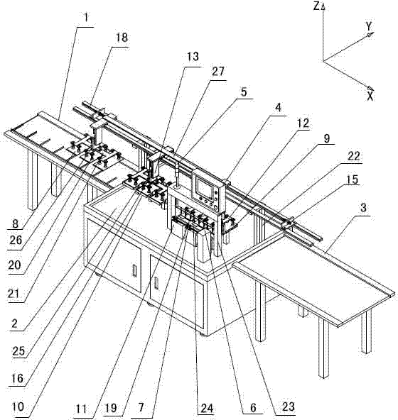
图1是直线式点焊机结构立体示意图。 Figure 1 is a three-dimensional schematic diagram of the structure of a linear spot welding machine.
图2是直线式点焊机主视示意图。 Fig. 2 is a schematic front view of the linear spot welding machine.
其中:1、前输送线 2、操作台 3、后输送线 4、控制面板 5、运行指示灯 6、焊头连接板 7、极耳 8、极片 9、点焊平台 10、定位台 11、极耳料盒 12、出料吸盘 13、移料吸盘 14、总行程气缸 15、定位器 16、吸极片气缸 17、点焊气缸 18、直线导轨 19、点焊焊头 20、真空吸盘 21、吸盘支架 22、导轨支架 23、点焊支架 24、上极耳支架 25、定位块 26、进料吸盘 27、传动板。
Among them: 1.
具体实施方式 Detailed ways
图1~2是本发明电容电池的直线式点焊机的最佳实施例,下面结合附图1~2对本发明做进一步说明。
Fig. 1 ~ 2 is the preferred embodiment of the linear spot welder of capacitor battery of the present invention, below in conjunction with accompanying
参照附图1~2:电容电池的直线式点焊机,包括操作台2、前输送线1、后输送线3、安装在操作台2上方的总移位装置和上极耳装置,固定在操作台2上的极片定位装置和点焊装置。操作台2为长方形,前输送线1设置在操作台2左侧,前输送线1上设有与极片8形状相适应的定位格,极片8经切割后不重叠的落入定位格中,后输送线3设置在操作台2右侧,极片定位装置固定在操作台2设有前输送线1的一端,点焊装置、上极耳装置固定在设有后输送线3的一端,极片定位装置、点焊装置与前、后输送线1、3呈直线分布,总移位装置沿前输送线1、操作台2和后输送线3的方向固定在操作台2上。
Referring to accompanying drawings 1-2: the linear spot welding machine of the capacitor battery, including the operating table 2, the
电容电池的极片8在点焊前后有四个工位,依次是沿X轴正方向的前输送线工位、定位工位、点焊工位和后输送线工位。极片8通过总移位装置实现在各工位间的直线传送。
The
总移位装置包括直线导轨18、导轨支架22、进料吸盘26、移料吸盘13、出料吸盘12、总行程气缸14、定位器15和传动板27,直线导轨18沿X轴方向通过导轨支架22固定在操作台2上且两端延伸至前、后输送线1、3的上方,进料吸盘26、移料吸盘13、出料吸盘12分别通过滑块沿X轴正方向依次连接在直线导轨18上,进料吸盘26、移料吸盘13、出料吸盘12位置相对固定的串联固定在传动板27上,总行程气缸14固定在直线导轨18的下方,总行程气缸14活塞杆外端与传动板27固定连接,进料吸盘26、移料吸盘13和出料吸盘12结构相同,均由吸极片气缸16、吸盘支架21和真空吸盘20组成,吸极片气缸16竖直设置,吸盘支架21与吸极片气缸16的活塞杆外端连接,吸盘支架21上设有三组真空吸盘20,每组真空吸盘20有四个,分别对应极片8的四个角,吸盘支架21可同时吸起三个极片。
The total displacement device includes a
极片定位装置包括三个沿X轴方向并排设置的定位台10,定位台10为长方形大小与极片8相适应,定位台10在X、Y轴负方向的两条侧边向上凸起,与之相对的另外两条与定位台10台面齐平的侧边一侧分别设有可活动的定位块25,定位块25上端高于定位台10,两个定位块25分别与固定在定位台10下方的定位气缸连接,定位气缸活塞杆收缩后定位块25分别紧靠在定位台10的侧边上。
The pole piece positioning device includes three
点焊装置包括点焊平台9、点焊支架23、点焊焊头19、焊头连接板6和点焊气缸17,点焊平台9与定位台10等高可同时放置三个极片8,点焊焊头19位于点焊平台9在Y轴负方向一端的正上方,点焊焊头19分三组,分别对应三个极片的焊接边,每组焊头包括3个X轴方向等距设置的点焊焊头19,点焊焊头19均竖直固定在一块焊头连接板6上,焊头连接板6两端分别连接在两个点焊气缸17活塞杆外端,点焊气缸17竖直固定在点焊支架23上,点焊支架23包括固定在点焊平台9在Y轴负方向两侧的操作台2上的两根支柱和固定在两根支柱上端的水平板。控制面板4和运行指示灯5均竖直固定在点焊支架23的水平板上。
The spot welding device comprises a
上极耳装置位于点焊装置Y轴的负方向,上极耳装置包括极耳料盒11、顶料器、上极耳支架24和真空吸盘20,极耳料盒11固定在点焊平台9在Y轴负方向的一侧,极耳料盒11有三个,与点焊平台9上的极片放置位置相适应,极耳料盒11的底部设有顶料器,顶料器在传感器的控制下保证极耳料盒11内的极耳7上端面高度,上极耳支架24位于三个极耳料盒11的上方,上极耳支架24上固定有沿X轴方向的三组真空吸盘20,三组真空吸盘20分别对应极耳料盒11内的极耳7,每组真空吸盘20有两个,上极耳支架24一端固定在可以沿Z轴方向移动的气缸上,沿Z轴方向移动的气缸又固定在可以沿Y轴方向移动的气缸上,上极耳支架24将极耳7从极耳料盒11内吸起后水平移动到极片8焊接边的上方,然后再压下。
The upper lug device is located in the negative direction of the Y axis of the spot welding device. The upper lug device includes a tab material box 11, a feeder, an
工作原理与工作过程如下:极片8经切割后不重叠的落入前输送线1的定位格内,前输送线1输送极片8到操作台2前端,进料吸盘26下压吸起极片将极片由前输送线工位送至定位工位,极片8送到定位台10后,极片8水平稍伸出定位台10的X、Y轴正方向,定位气缸动作,定位块25以及定位台10在X、Y轴负方向的两条凸边完成对极片8的定位。
The working principle and working process are as follows: after cutting, the
移料吸盘13下压吸起定位后的极片8送至点焊工位,极片8送到点焊平台9后,出料吸盘12下压压住极片8,同时上极耳装置开始动作,上极耳支架24下压,三组真空吸盘20分别吸住三个极耳7后上极耳支架24抬起,然后上极耳支架24沿Y轴正方向移动到极片8焊接边上方,上极耳支架24下压将极耳7焊接边压紧在极片8焊接边上,极耳料盒底11部的顶料器在传感器的控制下保证极耳料盒11内的极耳7上端面高度。
The material
点焊装置开始动作,点焊气缸17下压,三组点焊焊头19分别压紧在三个极耳7焊接边上,多焊点控制器开始工作,点焊完成后点焊气缸17归位,完成点焊,同时上极耳支架24归位,出料吸盘12将点焊完毕的极片8吸起并送至后输送线3完成一次循环。
The spot welding device starts to move, and the
进料吸盘26、移料吸盘13和出料吸盘12均固定在传动板27上,在X轴方向的移动是同时进行的,在进料吸盘26下压吸起极片8将极片8由前输送线工位送至定位工位的同时,移料吸盘13下压吸起极片8将极片8由定位工位送至点焊工位,出料吸盘12下压吸起点焊后的极片8将极片8由点焊工位送至后输送线工位,通过不断循环完成连续性生产。
The
通过控制面板4可手工调节总移位装置、极片定位装置、点焊装置和上极耳装置的单独动作,整个运行过程中,运行指示灯5显示当前运行状况,如果出现不正常工作现象,设备自动停止运行,且运行指示灯5发出报警信号。
Through the control panel 4, the individual actions of the total displacement device, the pole piece positioning device, the spot welding device and the upper tab device can be manually adjusted. During the entire operation process, the
以上所述,仅是本发明的较佳实施例而已,并非是对本发明作其它形式的限制,任何熟悉本专业的技术人员可能利用上述揭示的技术内容加以变更或改型为等同变化的等效实施例。但是凡是未脱离本发明技术方案内容,依据本发明的技术实质对以上实施例所作的任何简单修改、等同变化与改型,仍属于本发明技术方案的保护范围。 The above is only a preferred embodiment of the present invention, and is not intended to limit the present invention to other forms. Any skilled person who is familiar with this profession may use the technical content disclosed above to change or modify the equivalent of equivalent changes. Example. However, any simple modifications, equivalent changes and modifications made to the above embodiments according to the technical essence of the present invention without departing from the content of the technical solution of the present invention still belong to the protection scope of the technical solution of the present invention.
Claims (10)
Priority Applications (1)
| Application Number | Priority Date | Filing Date | Title |
|---|---|---|---|
| CN201210561660.8A CN103008864B (en) | 2012-12-22 | 2012-12-22 | Straight-line type spot welding machine of capacitor battery |
Applications Claiming Priority (1)
| Application Number | Priority Date | Filing Date | Title |
|---|---|---|---|
| CN201210561660.8A CN103008864B (en) | 2012-12-22 | 2012-12-22 | Straight-line type spot welding machine of capacitor battery |
Publications (2)
| Publication Number | Publication Date |
|---|---|
| CN103008864A true CN103008864A (en) | 2013-04-03 |
| CN103008864B CN103008864B (en) | 2015-04-29 |
Family
ID=47958270
Family Applications (1)
| Application Number | Title | Priority Date | Filing Date |
|---|---|---|---|
| CN201210561660.8A Expired - Fee Related CN103008864B (en) | 2012-12-22 | 2012-12-22 | Straight-line type spot welding machine of capacitor battery |
Country Status (1)
| Country | Link |
|---|---|
| CN (1) | CN103008864B (en) |
Cited By (15)
| Publication number | Priority date | Publication date | Assignee | Title |
|---|---|---|---|---|
| CN103706936A (en) * | 2013-12-27 | 2014-04-09 | 珠海华冠电子科技有限公司 | Capacitor point welding machine |
| CN104210817A (en) * | 2013-08-09 | 2014-12-17 | 吴水鱼 | Combined type stream welding machine and working principle thereof |
| CN104347889A (en) * | 2013-11-21 | 2015-02-11 | 深圳市东博自动化设备有限公司 | Automatic point welding machine for battery |
| CN104439793A (en) * | 2014-12-02 | 2015-03-25 | 东莞市斯宇自动化设备有限公司 | A stacking and feeding station of an automatic welding line |
| CN105458498A (en) * | 2015-12-25 | 2016-04-06 | 苏州达力客自动化科技有限公司 | Laser welding machine for cell pole column |
| CN106584110A (en) * | 2016-12-24 | 2017-04-26 | 秦皇岛航天华世自动化设备有限公司 | Capacitive automatic forming welding machine |
| CN107234380A (en) * | 2017-07-31 | 2017-10-10 | 英利能源(中国)有限公司 | Without hot spot photovoltaic module welding diode equipment and welding method |
| CN109176038A (en) * | 2018-11-02 | 2019-01-11 | 李青华 | Automobile wheel speed sensor production equipment |
| CN109500611A (en) * | 2019-01-15 | 2019-03-22 | 张玉仙 | A kind of circular capacitor manufacturing machine |
| CN110280934A (en) * | 2019-07-16 | 2019-09-27 | 无锡金红鹰工业自动化有限公司 | A kind of H profile steel column welding workstation |
| CN111063555A (en) * | 2019-12-30 | 2020-04-24 | 荆门欧曼凯机电设备有限公司 | Welding assembly line and welding method for welding process of capacitor and electrode plate |
| CN111716058A (en) * | 2020-06-22 | 2020-09-29 | 安徽锐光电子科技有限公司 | Welding auxiliary equipment for capacitor production and using method thereof |
| CN112296552A (en) * | 2019-07-31 | 2021-02-02 | 武汉同凯汽车电机有限公司 | EPS has brush motor stator facing automatic welder |
| CN113414508A (en) * | 2021-05-24 | 2021-09-21 | 惠州市豪鹏科技有限公司 | Laminate polymer battery laser welding anchor clamps |
| CN116713578A (en) * | 2023-08-08 | 2023-09-08 | 普迪智能装备有限公司 | A power battery welding production line |
Citations (7)
| Publication number | Priority date | Publication date | Assignee | Title |
|---|---|---|---|---|
| JP2007229769A (en) * | 2006-03-01 | 2007-09-13 | Koyo Giken:Kk | Automatic spot welding machine |
| CN101439437A (en) * | 2008-12-09 | 2009-05-27 | 张家港市久诺杰科技有限公司 | Spot welding device of battery pole piece |
| CN201540913U (en) * | 2009-11-30 | 2010-08-04 | 深圳市赢合科技有限公司 | Tab welding device |
| CN102328152A (en) * | 2011-09-16 | 2012-01-25 | 江苏久诺杰电子科技有限公司 | Spot-welding machine for battery negative electrode plate |
| CN202278349U (en) * | 2011-10-18 | 2012-06-20 | 淄博国利新电源科技有限公司 | Automatic positioning device for pole piece |
| CN202389948U (en) * | 2011-12-14 | 2012-08-22 | 深圳市大族激光科技股份有限公司 | Plate material conveying and loading/unloading system |
| CN203045138U (en) * | 2012-12-22 | 2013-07-10 | 淄博国利新电源科技有限公司 | Linear point welding machine of capacitor battery |
-
2012
- 2012-12-22 CN CN201210561660.8A patent/CN103008864B/en not_active Expired - Fee Related
Patent Citations (7)
| Publication number | Priority date | Publication date | Assignee | Title |
|---|---|---|---|---|
| JP2007229769A (en) * | 2006-03-01 | 2007-09-13 | Koyo Giken:Kk | Automatic spot welding machine |
| CN101439437A (en) * | 2008-12-09 | 2009-05-27 | 张家港市久诺杰科技有限公司 | Spot welding device of battery pole piece |
| CN201540913U (en) * | 2009-11-30 | 2010-08-04 | 深圳市赢合科技有限公司 | Tab welding device |
| CN102328152A (en) * | 2011-09-16 | 2012-01-25 | 江苏久诺杰电子科技有限公司 | Spot-welding machine for battery negative electrode plate |
| CN202278349U (en) * | 2011-10-18 | 2012-06-20 | 淄博国利新电源科技有限公司 | Automatic positioning device for pole piece |
| CN202389948U (en) * | 2011-12-14 | 2012-08-22 | 深圳市大族激光科技股份有限公司 | Plate material conveying and loading/unloading system |
| CN203045138U (en) * | 2012-12-22 | 2013-07-10 | 淄博国利新电源科技有限公司 | Linear point welding machine of capacitor battery |
Cited By (20)
| Publication number | Priority date | Publication date | Assignee | Title |
|---|---|---|---|---|
| CN104210817A (en) * | 2013-08-09 | 2014-12-17 | 吴水鱼 | Combined type stream welding machine and working principle thereof |
| CN104347889A (en) * | 2013-11-21 | 2015-02-11 | 深圳市东博自动化设备有限公司 | Automatic point welding machine for battery |
| CN103706936A (en) * | 2013-12-27 | 2014-04-09 | 珠海华冠电子科技有限公司 | Capacitor point welding machine |
| CN104439793A (en) * | 2014-12-02 | 2015-03-25 | 东莞市斯宇自动化设备有限公司 | A stacking and feeding station of an automatic welding line |
| CN105458498A (en) * | 2015-12-25 | 2016-04-06 | 苏州达力客自动化科技有限公司 | Laser welding machine for cell pole column |
| CN106584110A (en) * | 2016-12-24 | 2017-04-26 | 秦皇岛航天华世自动化设备有限公司 | Capacitive automatic forming welding machine |
| CN106584110B (en) * | 2016-12-24 | 2018-07-10 | 秦皇岛航天华世自动化设备有限公司 | Capacitance automatic moulding bonding machine |
| CN107234380A (en) * | 2017-07-31 | 2017-10-10 | 英利能源(中国)有限公司 | Without hot spot photovoltaic module welding diode equipment and welding method |
| CN109176038A (en) * | 2018-11-02 | 2019-01-11 | 李青华 | Automobile wheel speed sensor production equipment |
| CN109500611A (en) * | 2019-01-15 | 2019-03-22 | 张玉仙 | A kind of circular capacitor manufacturing machine |
| CN110280934A (en) * | 2019-07-16 | 2019-09-27 | 无锡金红鹰工业自动化有限公司 | A kind of H profile steel column welding workstation |
| CN112296552A (en) * | 2019-07-31 | 2021-02-02 | 武汉同凯汽车电机有限公司 | EPS has brush motor stator facing automatic welder |
| CN112296552B (en) * | 2019-07-31 | 2022-08-30 | 武汉同凯汽车电机有限公司 | EPS has brush motor stator facing automatic welder |
| CN111063555A (en) * | 2019-12-30 | 2020-04-24 | 荆门欧曼凯机电设备有限公司 | Welding assembly line and welding method for welding process of capacitor and electrode plate |
| CN111063555B (en) * | 2019-12-30 | 2021-12-31 | 荆门欧曼凯机电设备有限公司 | Welding assembly line and welding method for welding process of capacitor and electrode plate |
| CN111716058A (en) * | 2020-06-22 | 2020-09-29 | 安徽锐光电子科技有限公司 | Welding auxiliary equipment for capacitor production and using method thereof |
| CN113414508A (en) * | 2021-05-24 | 2021-09-21 | 惠州市豪鹏科技有限公司 | Laminate polymer battery laser welding anchor clamps |
| CN113414508B (en) * | 2021-05-24 | 2023-10-27 | 惠州市豪鹏科技有限公司 | Laser welding fixture for soft package battery |
| CN116713578A (en) * | 2023-08-08 | 2023-09-08 | 普迪智能装备有限公司 | A power battery welding production line |
| CN116713578B (en) * | 2023-08-08 | 2023-10-13 | 普迪智能装备有限公司 | Welding production line for power battery |
Also Published As
| Publication number | Publication date |
|---|---|
| CN103008864B (en) | 2015-04-29 |
Similar Documents
| Publication | Publication Date | Title |
|---|---|---|
| CN103008864B (en) | Straight-line type spot welding machine of capacitor battery | |
| CN203045138U (en) | Linear point welding machine of capacitor battery | |
| CN108346826B (en) | Lithium battery packaging equipment | |
| CN102642089B (en) | Pole piece laser cutting machine | |
| CN206278681U (en) | A kind of battery automatic blanking equipment | |
| CN105081550B (en) | Automatic ultrasonic wave utmost point ear cladding welding equipment | |
| CN202279522U (en) | Automatic material feeder of pole piece | |
| CN106141542A (en) | A kind of welder of integration kitchen range | |
| CN202317673U (en) | Automatic production line of container | |
| CN204867159U (en) | Pull end lid multistation manipulator | |
| CN201161336Y (en) | Metal frame forming device | |
| CN105690091B (en) | Power battery fully-automatic production robot system | |
| CN201538065U (en) | A packing box folding machine | |
| CN112185674B (en) | Manipulator for automatically inserting iron into transformer iron core and using method | |
| CN204295120U (en) | Lithium-ion electric core lug ultrasonic welding machine | |
| CN220077859U (en) | Novel high-efficient glass burst material loading machine | |
| CN208648242U (en) | A kind of sucker automatic feeding | |
| CN202741912U (en) | Automatic multi-point welder | |
| CN206084224U (en) | Welding set of integrated cooking utensils | |
| CN205600295U (en) | Full -automatic production robot system of power battery | |
| CN204257741U (en) | Full-automatic lithium-ion electric core lug welder | |
| CN2683304Y (en) | Automatic Ultrasonic Welding Machine | |
| CN203738248U (en) | Steel bar feeding mechanism of spot welding machine | |
| CN105882157B (en) | Fully-automatic laser coder | |
| CN204295121U (en) | Lithium-ion electric core lug Automatic ultrasonic welding machine |
Legal Events
| Date | Code | Title | Description |
|---|---|---|---|
| C06 | Publication | ||
| PB01 | Publication | ||
| C10 | Entry into substantive examination | ||
| SE01 | Entry into force of request for substantive examination | ||
| C14 | Grant of patent or utility model | ||
| GR01 | Patent grant | ||
| CF01 | Termination of patent right due to non-payment of annual fee | ||
| CF01 | Termination of patent right due to non-payment of annual fee |
Granted publication date: 20150429 |