A kind of multi-functional substrate grinding and polishing apparatus and grinding and polishing method thereof
Technical field
The invention belongs to the Ultraprecision Machining field of planar substrates; Be specifically related to a kind of grinding and polishing leveling processing and attenuate processing that is used for hard brittle material planar substrates such as silicon chip, sapphire substrate and glass substrate, also can be used for the grinding and the polishing processing of planar sheets such as pottery, metal and composite.
Background technology
The ultra-precision surface processing of flat, thin sheet substrates such as silicon chip, sapphire substrate, face glass and potsherd and the processing of ultraprecise attenuate; Usually through manufacturing procedures such as grinding, grinding and polishings; Independently accomplished by grinding, lapping machine and burnishing machine respectively, grinding, lapping machine are used for the surfacing processing of substrate, make substrate reach predetermined thickness; Obtain the high-quality surface of high-flatness; Burnishing machine is used for the surface finish of substrate, removes grinding, the lapped face damage layer of substrate, makes substrate reach the not damaged super-smooth surface.At present, the attenuate of substrate processing requires the substrate thickness thinning to reach below 30~100 μ m to make substrate in light weight and tight usually.When this moment, substrate was thinned to predetermined thickness through grinding usually, unload, refill to clip to and polish processing on the polishing machine from grinding machine; From the process of the conversion that is ground to polishing; Because the substrate surface grinding stress can cause the distortion of substrate, make substrate transmit between grinding and polishing process and on polishing machine, be very easy to fragmentation in the clamping process again, and adopt two lathes to carry out grinding and polishing processing respectively; Equipment investment is big, and production efficiency is lower.Common in the market substrate grinding and rubbing down scraper bed are generally special-purpose grinding equipment, as for disk shape silicon chip, mainly carry out leveling processing and attenuate processing with silicon chip ultraprecise grinding machine, carry out surface finish with the plane polishing lathe again; For the face glass of square sheet, mainly carry out leveling processing and attenuate processing with the private use plane lapping machine, carry out surface finish with the plane polishing lathe again.These existing grindings and burnishing machine often are not suitable for the different instructions for uses of multiple substrate.
Summary of the invention
The technical barrier that the present invention will solve is the deficiency that overcomes above-mentioned existing grinding and burnishing machine and processing method, has invented a kind of multi-functional substrate grinding and polishing apparatus and grinding and polishing method thereof.This multi-functional substrate grinding and polishing apparatus adopts two main axle structures; On an equipment, accomplish the grinding and the polishing processing of substrates such as silicon chip, face glass, potsherd, sapphire substrate; After promptly passing through grinding; Substrate need not unload sheet, directly gets into the polishing station from the grinding station and carries out substrate polishing processing, can realize the multiple grinding and polishing methods such as axial cut-in type grinding and polishing, radially cut-in type grinding and polishing, radially reciprocating type grinding and polishing and Liu Bian grinding and polishing of substrate.Grinding spindle unit and buff spindle unit be counterweight each other, a shared cover motor-driven feed mechanism and a cylinder feed mechanism, and substrate can realize deciding journey grinding and two kinds of feeding control modes of control grinding in grinding or polishing process.
The technical scheme that the present invention adopts is a kind of multi-functional substrate grinding and polishing apparatus and grinding and polishing method thereof; Its grinding and polishing method adopts three kinds of modes: 1) when adopting axial cut-in type grinding and polishing method to process disk shape substrate; Processed substrate W is placed on the sucker 12; Workbench 3 along continuous straight runs under the driving of feed mechanism 8 move forward to towards the b direction of arrow grinding spindle unit 18 below, with the outer edge that is centered close to emery wheel 15 of disk shape substrate W, keep workbench 3 fixed-site in the horizontal direction; 2) when adopting radially the cut-in type grinding and polishing method side of processing sheet-form substrate, emery wheel 15 rotation directions of grinding spindle unit 18 are that e is to rotation; Simultaneously, grinding spindle unit 18 along the downward feeding of the d of grinding and feeding direction, keeps grinding spindle unit 18 fixed-site on the grinding and feeding direction when motor 26 is just changeing; 3) when employing minor diameter emery wheel or throwing wheel, adopt and stay grinding and polishing method in limit to realize staying the limit grinding or staying edge polishing, the diameter that minor diameter emery wheel or throwing are taken turns is slightly less than the radius of processed substrate W, processed substrate W is carried place on the sucker 12;
In adopting said method during any one mode grinding; Earlier processed substrate W is adsorbed on the described sucker (12); Described sucker 12 is processed discoid by porous ceramic film material; Feed mechanism 8 drive described workbench 3 along continuous straight runs towards a to moving to 18 belows, described grinding spindle unit; Described grinding motor main shaft 17 drives described emery wheel 15 and rotates along the e direction of emery wheel rotation direction, and described motor 26 or described cylinder 39 drive described grinding spindle unit 18 along the grinding and feeding direction d feeding grinding substrate W that makes progress, and described device for measuring force 10 is transferred to the control system with the grinding force of monitoring; The control grinding force equals preset value; After described measuring thickness device 13 detected substrate W and reaches preset thickness, the grinding of substrate W was accomplished since then along described grinding vertical guide rail 23 rising withdrawings in described grinding spindle unit 18; Described feed mechanism 8 drive described workbench 3 along continuous straight runs towards a to moving to 35 belows, described buff spindle unit; Described polishing motor main shaft 36 drives described throwing wheel 37 and rotates along the h direction of throwing the wheel rotation direction; Described motor 26 or described cylinder 39 drives described buff spindle unit 35 along the polishing direction of feed g feeding grinding substrate W that makes progress; Described device for measuring force 10 is transferred to the control system with the polish pressure of monitoring; The control polish pressure equals preset value, and after the polish end, described buff spindle unit 35 is along described polishing vertical guide rail 30 rising withdrawings; Accomplish the polishing of substrate W since then; Described device for measuring force 10 detects grinding force or the polish pressure in the polishing process in the grinding process respectively, and will detect data and carry to the control system, guarantees that grinding force or polish pressure equal preset pressure; Described workbench 3 along continuous straight runs under the driving of described feed mechanism 8 unloads sheet towards a to shifting out the polishing processing district.
A kind of multi-functional substrate grinding and polishing apparatus; It is characterized in that; Grinding and polishing apparatus adopts two main axle structures of being made up of grinding spindle unit and buff spindle unit, on a table apparatus, accomplishes the grinding and the polishing processing of substrates such as silicon chip, face glass, potsherd, sapphire substrate; Multi-functional substrate grinding and polishing apparatus has rectangular-shaped pedestal 1; On pedestal 1, fixing a pair of horizontal guide rail 5; Guide slides 6 is contained on the horizontal guide rail 5; Slide plate 7 is fixed with guide slides 6, slide plate 7 be positioned on workbench 3 below, promptly workbench 3 is entrenched on a pair of horizontal guide rail 5 through guide slides 6 and slide plate 7; Base 9 be installed in workbench 3 above; Upper surface at base 9 is equipped with the circular device for measuring force 10 that is used for the on-line measurement grinding force, and measuring thickness device 13 is installed on the workbench 3; The workpiece motor shaft master 11 who is installed in workbench 3 centers is the inside that is enclosed within device for measuring force 10, and sucker 12 is installed in workpiece electric machine main shaft 11 tops, and feed mechanism 8 is connected with workbench 3;
Column 2 is installed in the middle part of pedestal 1, is installed with a pair of grinding vertical guide rail 23 at the leading flank of column 2, is installed on the grinding vertical guide rail 23 to the grinding spindle unit 18 that moves along vertical feed direction c or d; Be fixed on the trailing flank of column 2 along polishing direction of feed f and g to a pair of polishing vertical guide rail 30 that moves, buff spindle unit 35 is installed in and polishes on the guide rail 30; Grinding spindle unit 18 interconnects through hitch 25 with buff spindle unit 35, and hitch 25 is fixed on the preceding supporting seat 27 and back supporting seat 29 at column 2 tops through pull rope 28.
Described grinding spindle unit 18 has spindle drum 19, in the inside of spindle drum 19 grinding motor main shaft 17 is installed, and grinding spindle 17 lower ends are equipped with the emery wheel 15 that rotates along the e direction; Spindle drum 19 is installed on the slide carriage 21, and guide slides 22 is housed on slide carriage 21, slide carriage 21 through guide slides 22 be entrenched in do on a pair of grinding vertical guide rail 23 mobile; The screw mechanism 24 that is fixed in slide carriage 21 back sides is connected with motor 26 on the top; Said grinding motor main shaft 17 can drive said emery wheel 15 and rotate along emery wheel rotation direction e direction; Said motor 26 can drive grinding spindle unit 18 along grinding and feeding direction c or d to carrying out elevating movement; Also can drive simultaneously said buff spindle unit 35 and upwards carry out elevating movement along the f and the g that polish direction of feed, thus the feeding control mode that the journey grinding is decided in realization;
Described buff spindle unit 35 has spindle drum 33; In the inside of spindle drum 33 polishing motor main shaft 36 is installed; Polishing motor main shaft 36 lower ends are equipped with the throwing wheel 37 that rotates along the h direction, and spindle drum 33 is installed on the slide carriage 32, and 32 are equipped with guide slides 31 on slide carriage; 32 are entrenched in through guide slides 31 and do mobilely on a pair of polishing vertical guide rail 30 on the slide carriage, and buff spindle unit 35 moves up along polishing direction of feed f or g; Cylinder 39 is installed in parallel in polishing vertical guide rail 30 and gets the lower end; Cylinder 39 drive buff spindle unit 35 along the g of polishing directions of feed to descend or f to rising, under the traction of pull rope 28, grinding spindle unit 18 simultaneously along the c of grinding and feeding direction to rise or d to decline;
Described hitch 25 is separately fixed on the preceding supporting seat 27 and back supporting seat 29 at column 2 tops by pull rope 28; Pulley A41 and pulley B42 are installed on the preceding supporting seat 27; Pulley C43 and pulley D45 are installed on the supporting seat 29 of back, and pulley E44 and pulley F46 are installed in slide carriage 32 sides; The pull rope 28 that one end is fixed on the slide carriage 21 is walked around pulley A41, pulley C43, pulley E44, pulley F46, pulley D45 and pulley B42 respectively, is fixed at last on the slide carriage 21; Pull rope 28 links to each other described grinding spindle unit 18 with described buff spindle unit 35; Thereby making described grinding spindle unit 18 and described buff spindle unit 35 is counterweight each other, guarantees that described grinding spindle unit 18 has identical displacement with described buff spindle unit 35.
Remarkable result of the present invention is that multi-functional substrate grinding and polishing equipment is through being integrated in one milling drum and polishing machine; Buff spindle unit and grinding spindle unit are through a pull rope traction; Grinding spindle unit and buff spindle unit be counterweight each other; Grinding spindle unit and buff spindle units shared one cover motor-driven feed mechanism and cylinder feed mechanism can be realized multiple grinding and polishing processing mode.Adopt multi-functional substrate grinding and polishing equipment of the present invention can improve the efficient of grinding and polishing processing greatly, improve the precision of substrate, thereby can when reducing production costs, significantly improve the quality of products.
Description of drawings
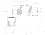
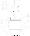
The structural representation of the multi-functional substrate grinding and polishing of Fig. 1 the present invention equipment; The hitch sketch map of the multi-functional substrate grinding and polishing of Fig. 2 the present invention equipment; The cutaway view of the multi-functional substrate grinding and polishing of Fig. 3 the present invention equipment; First kind and second kind described grinding and polishing method of embodiment of Fig. 4, the described grinding and polishing method of the third embodiment of Fig. 5.Among the figure: 1 pedestal, 2 columns, 3 workbench, 5 horizontal guide rails, 6 slide blocks, 7 slide plates, 8 feed mechanisms, 9 bases, 10 device for measuring force; 11 workpiece electric machine main shafts, 12 suckers, 13 measuring thickness devices, 15 emery wheels, 17 grinding motor main shafts, 18 grinding spindle unit, 19 spindle drums, 21 slide carriages; 22 slide blocks, 23 grinding vertical guide rails, 24 leading screw modules, 25 hitches, 26 motors, 27 preceding supporting seats, 28 pull ropes, 29 back supporting seats; 30 polishing vertical guide rails, 31 slide blocks, 32 slide carriages, 33 spindle drums, 35 buff spindle unit, 36 polishing motor main shafts, 37 throw wheel, 39 cylinders; 40 minor diameter emery wheels or throwing wheel, 41 pulley A, 42 pulley B, 43 pulley C, 44 pulley E, 45 pulley D, 46 pulley F, W substrate.
The specific embodiment
Specify practical implementation of the present invention below in conjunction with accompanying drawing and technical scheme.The grinding and polishing processing method of multi-functional substrate grinding and polishing equipment is among the present invention: during grinding; Substrate W is adsorbed on the sucker 12; Sucker 12 is processed discoid by porous ceramic film material, to moving to 18 belows, grinding spindle unit, grinding motor main shaft 17 drives emery wheels 15 and rotates along the e direction of emery wheel rotation direction feed mechanism 8 driving workbench 3 along continuous straight runs towards a; Motor 26 or cylinder 39 drives grinding spindle unit 18 along the grinding and feeding direction d feeding grinding substrate W that makes progress; Device for measuring force 10 is transferred to the control system with the grinding force of monitoring, and the control grinding force equals preset value, after measuring thickness device 13 detects substrate W and reaches preset thickness; The grinding of substrate W is accomplished since then along grinding vertical guide rail 23 rising withdrawings in grinding spindle unit 18; Feed mechanism 8 drive workbench 3 along continuous straight runs towards a to moving to 35 belows, buff spindle unit; Polishing motor main shaft 36 drives the h direction of throwing wheel 37 edge throwing wheel rotation directions and rotates; Motor 26 or cylinder 39 drives buff spindle unit 35 along the polishing direction of feed g feeding grinding substrate W that makes progress, and device for measuring force 10 is transferred to the control system with the polish pressure of monitoring, and the control polish pressure equals preset value; After the polish end; The polishing of substrate W is accomplished since then along polishing vertical guide rails 30 rising withdrawings in buff spindle unit 35, and device for measuring force 10 detects grinding force or the polish pressure in the polishing process in the grinding process respectively; And will detect data and carry to the control system, guarantee that grinding force or polish pressure equal preset pressure; Workbench 3 along continuous straight runs under the driving of feed mechanism 8 unloads sheet towards a to shifting out the polishing processing district, sees Fig. 1.
Multi-functional substrate grinding and polishing equipment has rectangular-shaped pedestal 1, on pedestal 1, is fixing a pair of horizontal guide rail 5 that extends along fore-and-aft direction, and the workbench 3 of carrying substrates W is installed on the horizontal guide rail 5, and workbench 3 can be along a or b to moving.The middle part of pedestal 1 uprightly is being provided with column 2, and a pair of grinding vertical guide rail 23 is fixed on the leading flank of column 2, and grinding spindle unit 18 is positioned on the grinding vertical guide rail 23, and the grinding spindle unit 18 that is used for grinding can be along grinding and feeding direction c or d to moving.A pair of polishing vertical guide rail 30 is fixed on the trailing flank of column 2, and the buff spindle unit 35 that is used to polish is positioned on polishing vertical guide rail 30, and Fig. 2 can be seen along polishing direction of feed f and g to moving in buff spindle unit 35.Grinding spindle unit 18 interconnects through hitch 25 with buff spindle unit 35; Hitch 25 is by pull rope 28; Be fixed in the preceding supporting seat 27 and back supporting seat 29 at column 2 tops; And pulley A41 and the pulley B42 on the supporting seat 27 before being positioned on, be disposed at pulley C43 and pulley D45 on the supporting seat 29 of back and pulley E44 and the pulley F46 that is disposed at slide carriage 32 sides.One end is fixed in slide carriage 21 upper left pull ropes 28 walks around pulley A41, pulley C43, pulley E44, pulley F46, pulley D45 and pulley B42 respectively, and it is upper right to be fixed in slide carriage 21 at last.Adopt 28 tractions of a pull rope, can guarantee that the both sides of slide carriage 21 and slide carriage 32 receive identical tractive force, in order to avoid increase tilting moment.Certainly, above-mentioned baudrier only is one of them scheme, and this patent is not limited to this scheme, also can be with above-mentioned slide carriage 21 and slide carriage 32 exchange schemes.
In conjunction with Fig. 1 and Fig. 3, workbench 3 drives in the horizontal direction through feed mechanism 8 and moves, and feed mechanism 8 can be the structure of linear module or linear electric motors or " servomotor+lead screw pair ".This workbench 3 the driving along continuous straight runs of following time of feed mechanism 8 towards a to for reach or towards b to for retreating.Workbench 3 has base 9; Upper surface at base 9 is equipped with the circular device for measuring force 10 that is used for the on-line measurement grinding force; Device for measuring force 10 detects grinding force or the polish pressure in the polishing process in the grinding process respectively; And will detect data and carry to the control system, guarantee that grinding force or polish pressure equal preset pressure; The workpiece main motor shaft 11 that is enclosed within the inside of device for measuring force 10 and in horizontal plane, can rotates; What be assemblied in main motor shaft 11 upper ends forms discoid sucker 12 by porous ceramic film material; With processed substrate W be placed on sucker 12 above, the i of sucker 12 sucker rotation direction in the driving lower edge of main motor shaft 11 is to rotation.In above-mentioned grinding and polishing processing, the thickness of substrate W is ground to preset thickness.Measuring thickness device 13 detects the height that is positioned the substrate W of maintenance on the sucker 12, and will detect data and carry to the control system, when grinding thickness reaches preset thickness, stops to process feeding.
In conjunction with Fig. 1 and Fig. 3; Above-mentioned grinding spindle unit 18 has spindle drum 19, in the inside of spindle drum 19 grinding spindle 17 is installed, and grinding spindle 17 lower ends are equipped with can free rotating emery wheel 15; Emery wheel rotation direction 16 is rotated along the e direction, and spindle drum 19 is installed on the slide carriage 21.On slide carriage 21, be provided with guide slides 22, through this guide slides 22 is entrenched on the pair of guide rails 23 movably, grinding spindle unit 18 moves on c or d direction along grinding and feeding direction 20.Grinding spindle unit 18 has the motor 26 that driving emery wheel 15 carries out grinding; Motor 26 drives the leading screw module 24 parallel with guide rail 23; This grinding spindle unit 18 when motor 26 is just changeing along the d in the grinding and feeding direction 20 to decline; Under the traction of pull rope 28, the f in the buff spindle unit 36 edge polishing simultaneously direction of feed 34 is to rising; When motor 26 counter-rotating grinding spindle unit 18 along the c in the grinding and feeding direction 20 to rising, buff spindle unit 36 simultaneously along the g in the polishing direction of feed 34 to decline.
In conjunction with Fig. 1 and Fig. 3; Above-mentioned buff spindle unit 35 has spindle drum 33, in the inside of spindle drum 33 buff spindle 36 is installed, and buff spindle 36 lower ends are equipped with and can free rotating throwing take turns 37; Throw wheel rotation direction 38 and rotate along the h direction, spindle drum 33 is installed on the slide carriage 32.32 are provided with guide slides 31 on slide carriage, and through this guide slides 31 is entrenched on the pair of guide rails 30 movably, buff spindle unit 35 moves on f or g direction along polishing direction of feed 34.Buff spindle unit 35 has drive to throw that polish and parallel with guide rail 30 cylinder 39 of wheel 37.This buff spindle unit 35 when the logical compressed air of cylinder 39 upper cavities along the g in the polishing direction of feed 34 to decline, under the traction of pull rope 28, grinding spindle unit 18 simultaneously along the c in the grinding and feeding direction 20 to rising; When the logical compressed air of cylinder 39 lower chambers along the f in the polishing direction of feed 34 to rising, grinding spindle unit 18 simultaneously along the d in the grinding and feeding direction 20 to decline.
Embodiment one, adopts axial cut-in type grinding and polishing method processing disk shape substrate, sees Fig. 4.Processed substrate W is placed on the sucker 12; Workbench 3 along continuous straight runs under the driving of feed mechanism 8 move forward to towards the b direction of arrow grinding spindle unit 18 below; With the outer edge that is centered close to emery wheel 15 of disk shape substrate W, keep workbench 3 fixed-site in the horizontal direction.Under the driving of work spindle 11, make substrate W along sucker rotation direction i to rotation.The emery wheel 15 of grinding spindle unit 18 along emery wheel rotation direction 1e to rotation; Simultaneously, grinding spindle unit 18 when motor 26 is just changeing along the d of grinding and feeding direction to feeding, consequently, the substrate W on the sucker 12 is implemented traditional journey grinding of deciding.Perhaps grinding spindle unit 18 at the logical compressed air of cylinder 39 lower chambers constantly along the d of grinding and feeding direction to feeding; Consequently; Substrate W on the sucker 12 is implemented the control grinding; After thickness that measuring thickness device 13 detects substrate W arrives preset thickness, grinding spindle unit 18 when motor 26 counter-rotatings along the c of grinding and feeding direction to the rising withdrawing.After grinding finishes; Workbench 3 along continuous straight runs under the driving of feed mechanism 8 move forward to towards the b direction of arrow buff spindle unit 35 below; The outer edge of throwing wheel 37 that is centered close to with disk shape substrate W keeps workbench 3 fixed-site in the horizontal direction.Under the driving of workpiece main motor shaft 11, substrate W is rotated along sucker rotation direction i direction.The throwing of buff spindle unit 35 wheel 37 in rotational direction h to rotation.Simultaneously, buff spindle unit 35 along the downward feeding of g of polishing direction of feed, consequently, is implemented traditional journey polishing of deciding to the substrate W on the sucker 12 and is processed when motor 26 counter-rotatings.Perhaps control polishing processing constantly along the downward feeding of g of polishing direction of feed, consequently, is implemented to the substrate W on the sucker 12 at the logical compressed air of cylinder 39 upper cavities in buff spindle unit 35.After the polishing completion of processing, workbench 3 along continuous straight runs under the driving of feed mechanism 8 unloads sheet towards a to shifting out the polishing processing district.
Embodiment two, adopt the radially cut-in type grinding and polishing method side of processing sheet-form substrate, see Fig. 4.Emery wheel 15 rotation directions of grinding spindle unit 18 are that e is to rotation.Simultaneously, grinding spindle unit 18 along the downward feeding of the d of grinding and feeding direction, keeps grinding spindle unit 18 fixed-site on the grinding and feeding direction when motor 26 is just changeing; Workbench 3 under the driving of feed mechanism 8 along continuous straight runs towards b to moving; Outward flange until substrate W EDGE CONTACT emery wheel 15 begins grinding, and to moving, the outward flange that breaks away from emery wheel 15 until substrate W edge finishes grinding to the continuation along continuous straight runs towards b; Workbench 3 under the driving of feed mechanism 8 along continuous straight runs towards a to moving; Return the grinding initial position, measuring thickness device 13 is measured the thickness of substrate W, accomplishes the grinding of first leg; Then; Grinding spindle unit 18 when motor 26 is just changeing along the d of grinding and feeding direction to continuing necessarily removal amount of feeding, keep grinding spindle unit 18 fixed-site on the grinding and feeding direction, carry out the grinding of second leg; By that analogy, be ground to preset grinding thickness until substrate W.After grinding finishes; Workbench 3 along continuous straight runs under the driving of feed mechanism 8 towards b to move forward to buff spindle unit 35 below; With the outer edge of throwing wheel 37 that is centered close to disk shape substrate W; Keep workbench 3 before and after on a and the b direction, to swing in the horizontal direction, under the driving of workpiece main motor shaft 11, make substrate W along the i of sucker rotation direction to rotation; The throwing wheel 37 of buff spindle unit 35 is so that along throwing the rotation of wheel rotation direction h direction.Simultaneously, buff spindle unit 35 when motor 26 counter-rotating along the g of polishing direction of feed to the decline feeding, consequently, the substrate W on the sucker 12 is implemented traditional journey polishing processing of deciding.Perhaps control polishing processing to downward feeding, consequently, is implemented to the substrate W on the sucker 12 at the g of the logical compressed air of cylinder 39 upper cavities edge polishing constantly direction of feed in buff spindle unit 35.After the polishing completion of processing, workbench 3 along continuous straight runs under the driving of feed mechanism 8 unloads sheet towards a to shifting out the polishing processing district.
Embodiment three, adopt and stay the processing of limit grinding and polishing method, see Fig. 5.When adopting minor diameter emery wheel or throwing to take turns 40, can realize staying the limit grinding or stay edge polishing, the diameter of 40 minor diameter emery wheels or throwing wheel is slightly less than the radius of substrate W.Processed substrate W carried place on the sucker 12; Workbench 3 along continuous straight runs under the driving of feed mechanism 8 towards b to move forward to grinding spindle unit 18 below; So that the outward flange of emery wheel 15, keeps workbench 3 fixed-site in the horizontal direction through the center of disk shape substrate W.Under the driving of workpiece main motor shaft 11, make substrate W along the i of sucker rotation direction to rotation.The emery wheel 15 of grinding spindle unit 18 so as along emery wheel rotation direction e to rotation; Simultaneously, traditional journey grinding of deciding along the downward feeding of the d of grinding and feeding direction, consequently, is implemented to the substrate W on the sucker 12 in grinding spindle unit 18 when motor 26 is just changeing.Perhaps grinding spindle unit 18 at the logical compressed air of cylinder 39 lower chambers constantly along the d of grinding and feeding direction to downward feeding; Consequently; Substrate W on the sucker 12 is implemented the control grinding; After thickness that measuring thickness device 13 detects substrate W arrives preset thickness, grinding spindle unit 18 when motor 26 counter-rotatings along the c of grinding and feeding direction to the rising withdrawing.Substrate W after the grinding remains with the not grinding of limit of annular on excircle, be used to improve the intensity of substrate W.After grinding finishes; Workbench 3 along continuous straight runs under the driving of feed mechanism 8 towards b to move forward to buff spindle unit 35 below; So that throw the center of the outward flange of wheel 37, keep workbench 3 fixed-site in the horizontal direction through disk shape substrate W.Under the driving of workpiece main motor shaft 11, make the i direction rotation of substrate W along the sucker rotation direction.The throwing wheel 37 of buff spindle unit 35 is so that along throwing wheel rotation direction h to rotation; Simultaneously, buff spindle unit 35 when motor 26 counter-rotating along the g of polishing direction of feed to downward feeding, consequently, the substrate W on the sucker 12 is implemented traditional journey polishing processing of deciding.Perhaps control polishing processing constantly along the downward feeding of g of polishing direction of feed, consequently, is implemented to the substrate W on the sucker 12 at the logical compressed air of cylinder 39 upper cavities in buff spindle unit 35.Substrate W after the polishing remains with the limit of annular and does not polish on excircle, be used to improve the intensity of substrate W.After the polishing completion of processing, workbench 3 along continuous straight runs under the driving of feed mechanism 8 shifts out the polishing processing district towards a direction of arrow and unloads sheet.
The present invention also has the embodiment of various ways, all can realize multiple mill, throw processing mode.Adopt multi-functional substrate grinding and polishing equipment of the present invention can improve the efficient of grinding and polishing processing and the machining accuracy of substrate greatly, reduce production costs, significantly improve the quality of products.