CN102136472B - Semiconductor apparatus module - Google Patents
Semiconductor apparatus module Download PDFInfo
- Publication number
- CN102136472B CN102136472B CN201010571357.7A CN201010571357A CN102136472B CN 102136472 B CN102136472 B CN 102136472B CN 201010571357 A CN201010571357 A CN 201010571357A CN 102136472 B CN102136472 B CN 102136472B
- Authority
- CN
- China
- Prior art keywords
- main electrode
- electrode terminal
- heating panel
- semiconductor apparatus
- apparatus mould
- Prior art date
- Legal status (The legal status is an assumption and is not a legal conclusion. Google has not performed a legal analysis and makes no representation as to the accuracy of the status listed.)
- Active
Links
Images


Classifications
-
- H—ELECTRICITY
- H01—ELECTRIC ELEMENTS
- H01L—SEMICONDUCTOR DEVICES NOT COVERED BY CLASS H10
- H01L23/00—Details of semiconductor or other solid state devices
- H01L23/34—Arrangements for cooling, heating, ventilating or temperature compensation ; Temperature sensing arrangements
- H01L23/40—Mountings or securing means for detachable cooling or heating arrangements ; fixed by friction, plugs or springs
-
- H—ELECTRICITY
- H01—ELECTRIC ELEMENTS
- H01L—SEMICONDUCTOR DEVICES NOT COVERED BY CLASS H10
- H01L23/00—Details of semiconductor or other solid state devices
- H01L23/34—Arrangements for cooling, heating, ventilating or temperature compensation ; Temperature sensing arrangements
-
- H—ELECTRICITY
- H01—ELECTRIC ELEMENTS
- H01L—SEMICONDUCTOR DEVICES NOT COVERED BY CLASS H10
- H01L23/00—Details of semiconductor or other solid state devices
- H01L23/12—Mountings, e.g. non-detachable insulating substrates
-
- H—ELECTRICITY
- H01—ELECTRIC ELEMENTS
- H01L—SEMICONDUCTOR DEVICES NOT COVERED BY CLASS H10
- H01L23/00—Details of semiconductor or other solid state devices
- H01L23/28—Encapsulations, e.g. encapsulating layers, coatings, e.g. for protection
- H01L23/31—Encapsulations, e.g. encapsulating layers, coatings, e.g. for protection characterised by the arrangement or shape
- H01L23/3107—Encapsulations, e.g. encapsulating layers, coatings, e.g. for protection characterised by the arrangement or shape the device being completely enclosed
- H01L23/3121—Encapsulations, e.g. encapsulating layers, coatings, e.g. for protection characterised by the arrangement or shape the device being completely enclosed a substrate forming part of the encapsulation
-
- H—ELECTRICITY
- H01—ELECTRIC ELEMENTS
- H01L—SEMICONDUCTOR DEVICES NOT COVERED BY CLASS H10
- H01L23/00—Details of semiconductor or other solid state devices
- H01L23/48—Arrangements for conducting electric current to or from the solid state body in operation, e.g. leads, terminal arrangements ; Selection of materials therefor
-
- H—ELECTRICITY
- H01—ELECTRIC ELEMENTS
- H01L—SEMICONDUCTOR DEVICES NOT COVERED BY CLASS H10
- H01L24/00—Arrangements for connecting or disconnecting semiconductor or solid-state bodies; Methods or apparatus related thereto
- H01L24/01—Means for bonding being attached to, or being formed on, the surface to be connected, e.g. chip-to-package, die-attach, "first-level" interconnects; Manufacturing methods related thereto
- H01L24/26—Layer connectors, e.g. plate connectors, solder or adhesive layers; Manufacturing methods related thereto
- H01L24/28—Structure, shape, material or disposition of the layer connectors prior to the connecting process
- H01L24/29—Structure, shape, material or disposition of the layer connectors prior to the connecting process of an individual layer connector
-
- H—ELECTRICITY
- H01—ELECTRIC ELEMENTS
- H01L—SEMICONDUCTOR DEVICES NOT COVERED BY CLASS H10
- H01L24/00—Arrangements for connecting or disconnecting semiconductor or solid-state bodies; Methods or apparatus related thereto
- H01L24/01—Means for bonding being attached to, or being formed on, the surface to be connected, e.g. chip-to-package, die-attach, "first-level" interconnects; Manufacturing methods related thereto
- H01L24/34—Strap connectors, e.g. copper straps for grounding power devices; Manufacturing methods related thereto
- H01L24/36—Structure, shape, material or disposition of the strap connectors prior to the connecting process
- H01L24/37—Structure, shape, material or disposition of the strap connectors prior to the connecting process of an individual strap connector
-
- H—ELECTRICITY
- H01—ELECTRIC ELEMENTS
- H01L—SEMICONDUCTOR DEVICES NOT COVERED BY CLASS H10
- H01L24/00—Arrangements for connecting or disconnecting semiconductor or solid-state bodies; Methods or apparatus related thereto
- H01L24/01—Means for bonding being attached to, or being formed on, the surface to be connected, e.g. chip-to-package, die-attach, "first-level" interconnects; Manufacturing methods related thereto
- H01L24/34—Strap connectors, e.g. copper straps for grounding power devices; Manufacturing methods related thereto
- H01L24/39—Structure, shape, material or disposition of the strap connectors after the connecting process
- H01L24/40—Structure, shape, material or disposition of the strap connectors after the connecting process of an individual strap connector
-
- H—ELECTRICITY
- H01—ELECTRIC ELEMENTS
- H01L—SEMICONDUCTOR DEVICES NOT COVERED BY CLASS H10
- H01L24/00—Arrangements for connecting or disconnecting semiconductor or solid-state bodies; Methods or apparatus related thereto
- H01L24/80—Methods for connecting semiconductor or other solid state bodies using means for bonding being attached to, or being formed on, the surface to be connected
- H01L24/84—Methods for connecting semiconductor or other solid state bodies using means for bonding being attached to, or being formed on, the surface to be connected using a strap connector
-
- H—ELECTRICITY
- H01—ELECTRIC ELEMENTS
- H01L—SEMICONDUCTOR DEVICES NOT COVERED BY CLASS H10
- H01L25/00—Assemblies consisting of a plurality of individual semiconductor or other solid state devices ; Multistep manufacturing processes thereof
- H01L25/03—Assemblies consisting of a plurality of individual semiconductor or other solid state devices ; Multistep manufacturing processes thereof all the devices being of a type provided for in the same subgroup of groups H01L27/00 - H01L33/00, or in a single subclass of H10K, H10N, e.g. assemblies of rectifier diodes
- H01L25/04—Assemblies consisting of a plurality of individual semiconductor or other solid state devices ; Multistep manufacturing processes thereof all the devices being of a type provided for in the same subgroup of groups H01L27/00 - H01L33/00, or in a single subclass of H10K, H10N, e.g. assemblies of rectifier diodes the devices not having separate containers
- H01L25/07—Assemblies consisting of a plurality of individual semiconductor or other solid state devices ; Multistep manufacturing processes thereof all the devices being of a type provided for in the same subgroup of groups H01L27/00 - H01L33/00, or in a single subclass of H10K, H10N, e.g. assemblies of rectifier diodes the devices not having separate containers the devices being of a type provided for in group H01L29/00
- H01L25/072—Assemblies consisting of a plurality of individual semiconductor or other solid state devices ; Multistep manufacturing processes thereof all the devices being of a type provided for in the same subgroup of groups H01L27/00 - H01L33/00, or in a single subclass of H10K, H10N, e.g. assemblies of rectifier diodes the devices not having separate containers the devices being of a type provided for in group H01L29/00 the devices being arranged next to each other
-
- H—ELECTRICITY
- H01—ELECTRIC ELEMENTS
- H01L—SEMICONDUCTOR DEVICES NOT COVERED BY CLASS H10
- H01L23/00—Details of semiconductor or other solid state devices
- H01L23/34—Arrangements for cooling, heating, ventilating or temperature compensation ; Temperature sensing arrangements
- H01L23/40—Mountings or securing means for detachable cooling or heating arrangements ; fixed by friction, plugs or springs
- H01L23/4006—Mountings or securing means for detachable cooling or heating arrangements ; fixed by friction, plugs or springs with bolts or screws
- H01L2023/4037—Mountings or securing means for detachable cooling or heating arrangements ; fixed by friction, plugs or springs with bolts or screws characterised by thermal path or place of attachment of heatsink
- H01L2023/4056—Mountings or securing means for detachable cooling or heating arrangements ; fixed by friction, plugs or springs with bolts or screws characterised by thermal path or place of attachment of heatsink heatsink to additional heatsink
-
- H—ELECTRICITY
- H01—ELECTRIC ELEMENTS
- H01L—SEMICONDUCTOR DEVICES NOT COVERED BY CLASS H10
- H01L2224/00—Indexing scheme for arrangements for connecting or disconnecting semiconductor or solid-state bodies and methods related thereto as covered by H01L24/00
- H01L2224/01—Means for bonding being attached to, or being formed on, the surface to be connected, e.g. chip-to-package, die-attach, "first-level" interconnects; Manufacturing methods related thereto
- H01L2224/26—Layer connectors, e.g. plate connectors, solder or adhesive layers; Manufacturing methods related thereto
- H01L2224/28—Structure, shape, material or disposition of the layer connectors prior to the connecting process
- H01L2224/29—Structure, shape, material or disposition of the layer connectors prior to the connecting process of an individual layer connector
- H01L2224/29001—Core members of the layer connector
- H01L2224/29099—Material
- H01L2224/291—Material with a principal constituent of the material being a metal or a metalloid, e.g. boron [B], silicon [Si], germanium [Ge], arsenic [As], antimony [Sb], tellurium [Te] and polonium [Po], and alloys thereof
- H01L2224/29101—Material with a principal constituent of the material being a metal or a metalloid, e.g. boron [B], silicon [Si], germanium [Ge], arsenic [As], antimony [Sb], tellurium [Te] and polonium [Po], and alloys thereof the principal constituent melting at a temperature of less than 400°C
- H01L2224/29111—Tin [Sn] as principal constituent
-
- H—ELECTRICITY
- H01—ELECTRIC ELEMENTS
- H01L—SEMICONDUCTOR DEVICES NOT COVERED BY CLASS H10
- H01L2224/00—Indexing scheme for arrangements for connecting or disconnecting semiconductor or solid-state bodies and methods related thereto as covered by H01L24/00
- H01L2224/01—Means for bonding being attached to, or being formed on, the surface to be connected, e.g. chip-to-package, die-attach, "first-level" interconnects; Manufacturing methods related thereto
- H01L2224/26—Layer connectors, e.g. plate connectors, solder or adhesive layers; Manufacturing methods related thereto
- H01L2224/28—Structure, shape, material or disposition of the layer connectors prior to the connecting process
- H01L2224/29—Structure, shape, material or disposition of the layer connectors prior to the connecting process of an individual layer connector
- H01L2224/29001—Core members of the layer connector
- H01L2224/29099—Material
- H01L2224/29198—Material with a principal constituent of the material being a combination of two or more materials in the form of a matrix with a filler, i.e. being a hybrid material, e.g. segmented structures, foams
- H01L2224/29199—Material of the matrix
- H01L2224/2929—Material of the matrix with a principal constituent of the material being a polymer, e.g. polyester, phenolic based polymer, epoxy
-
- H—ELECTRICITY
- H01—ELECTRIC ELEMENTS
- H01L—SEMICONDUCTOR DEVICES NOT COVERED BY CLASS H10
- H01L2224/00—Indexing scheme for arrangements for connecting or disconnecting semiconductor or solid-state bodies and methods related thereto as covered by H01L24/00
- H01L2224/01—Means for bonding being attached to, or being formed on, the surface to be connected, e.g. chip-to-package, die-attach, "first-level" interconnects; Manufacturing methods related thereto
- H01L2224/26—Layer connectors, e.g. plate connectors, solder or adhesive layers; Manufacturing methods related thereto
- H01L2224/28—Structure, shape, material or disposition of the layer connectors prior to the connecting process
- H01L2224/29—Structure, shape, material or disposition of the layer connectors prior to the connecting process of an individual layer connector
- H01L2224/29001—Core members of the layer connector
- H01L2224/29099—Material
- H01L2224/29198—Material with a principal constituent of the material being a combination of two or more materials in the form of a matrix with a filler, i.e. being a hybrid material, e.g. segmented structures, foams
- H01L2224/29298—Fillers
- H01L2224/29299—Base material
- H01L2224/293—Base material with a principal constituent of the material being a metal or a metalloid, e.g. boron [B], silicon [Si], germanium [Ge], arsenic [As], antimony [Sb], tellurium [Te] and polonium [Po], and alloys thereof
- H01L2224/29338—Base material with a principal constituent of the material being a metal or a metalloid, e.g. boron [B], silicon [Si], germanium [Ge], arsenic [As], antimony [Sb], tellurium [Te] and polonium [Po], and alloys thereof the principal constituent melting at a temperature of greater than or equal to 950°C and less than 1550°C
- H01L2224/29339—Silver [Ag] as principal constituent
-
- H—ELECTRICITY
- H01—ELECTRIC ELEMENTS
- H01L—SEMICONDUCTOR DEVICES NOT COVERED BY CLASS H10
- H01L2224/00—Indexing scheme for arrangements for connecting or disconnecting semiconductor or solid-state bodies and methods related thereto as covered by H01L24/00
- H01L2224/01—Means for bonding being attached to, or being formed on, the surface to be connected, e.g. chip-to-package, die-attach, "first-level" interconnects; Manufacturing methods related thereto
- H01L2224/34—Strap connectors, e.g. copper straps for grounding power devices; Manufacturing methods related thereto
- H01L2224/36—Structure, shape, material or disposition of the strap connectors prior to the connecting process
- H01L2224/37—Structure, shape, material or disposition of the strap connectors prior to the connecting process of an individual strap connector
- H01L2224/37001—Core members of the connector
- H01L2224/3701—Shape
- H01L2224/37011—Shape comprising apertures or cavities
-
- H—ELECTRICITY
- H01—ELECTRIC ELEMENTS
- H01L—SEMICONDUCTOR DEVICES NOT COVERED BY CLASS H10
- H01L2224/00—Indexing scheme for arrangements for connecting or disconnecting semiconductor or solid-state bodies and methods related thereto as covered by H01L24/00
- H01L2224/01—Means for bonding being attached to, or being formed on, the surface to be connected, e.g. chip-to-package, die-attach, "first-level" interconnects; Manufacturing methods related thereto
- H01L2224/34—Strap connectors, e.g. copper straps for grounding power devices; Manufacturing methods related thereto
- H01L2224/36—Structure, shape, material or disposition of the strap connectors prior to the connecting process
- H01L2224/37—Structure, shape, material or disposition of the strap connectors prior to the connecting process of an individual strap connector
- H01L2224/37001—Core members of the connector
- H01L2224/37099—Material
- H01L2224/371—Material with a principal constituent of the material being a metal or a metalloid, e.g. boron [B], silicon [Si], germanium [Ge], arsenic [As], antimony [Sb], tellurium [Te] and polonium [Po], and alloys thereof
- H01L2224/37138—Material with a principal constituent of the material being a metal or a metalloid, e.g. boron [B], silicon [Si], germanium [Ge], arsenic [As], antimony [Sb], tellurium [Te] and polonium [Po], and alloys thereof the principal constituent melting at a temperature of greater than or equal to 950°C and less than 1550°C
- H01L2224/37147—Copper [Cu] as principal constituent
-
- H—ELECTRICITY
- H01—ELECTRIC ELEMENTS
- H01L—SEMICONDUCTOR DEVICES NOT COVERED BY CLASS H10
- H01L2224/00—Indexing scheme for arrangements for connecting or disconnecting semiconductor or solid-state bodies and methods related thereto as covered by H01L24/00
- H01L2224/01—Means for bonding being attached to, or being formed on, the surface to be connected, e.g. chip-to-package, die-attach, "first-level" interconnects; Manufacturing methods related thereto
- H01L2224/34—Strap connectors, e.g. copper straps for grounding power devices; Manufacturing methods related thereto
- H01L2224/36—Structure, shape, material or disposition of the strap connectors prior to the connecting process
- H01L2224/37—Structure, shape, material or disposition of the strap connectors prior to the connecting process of an individual strap connector
- H01L2224/3754—Coating
- H01L2224/37599—Material
-
- H—ELECTRICITY
- H01—ELECTRIC ELEMENTS
- H01L—SEMICONDUCTOR DEVICES NOT COVERED BY CLASS H10
- H01L2224/00—Indexing scheme for arrangements for connecting or disconnecting semiconductor or solid-state bodies and methods related thereto as covered by H01L24/00
- H01L2224/01—Means for bonding being attached to, or being formed on, the surface to be connected, e.g. chip-to-package, die-attach, "first-level" interconnects; Manufacturing methods related thereto
- H01L2224/34—Strap connectors, e.g. copper straps for grounding power devices; Manufacturing methods related thereto
- H01L2224/39—Structure, shape, material or disposition of the strap connectors after the connecting process
- H01L2224/40—Structure, shape, material or disposition of the strap connectors after the connecting process of an individual strap connector
- H01L2224/401—Disposition
- H01L2224/40135—Connecting between different semiconductor or solid-state bodies, i.e. chip-to-chip
- H01L2224/40137—Connecting between different semiconductor or solid-state bodies, i.e. chip-to-chip the bodies being arranged next to each other, e.g. on a common substrate
- H01L2224/40139—Connecting between different semiconductor or solid-state bodies, i.e. chip-to-chip the bodies being arranged next to each other, e.g. on a common substrate with an intermediate bond, e.g. continuous strap daisy chain
-
- H—ELECTRICITY
- H01—ELECTRIC ELEMENTS
- H01L—SEMICONDUCTOR DEVICES NOT COVERED BY CLASS H10
- H01L2224/00—Indexing scheme for arrangements for connecting or disconnecting semiconductor or solid-state bodies and methods related thereto as covered by H01L24/00
- H01L2224/01—Means for bonding being attached to, or being formed on, the surface to be connected, e.g. chip-to-package, die-attach, "first-level" interconnects; Manufacturing methods related thereto
- H01L2224/42—Wire connectors; Manufacturing methods related thereto
- H01L2224/44—Structure, shape, material or disposition of the wire connectors prior to the connecting process
- H01L2224/45—Structure, shape, material or disposition of the wire connectors prior to the connecting process of an individual wire connector
- H01L2224/45001—Core members of the connector
- H01L2224/45099—Material
- H01L2224/451—Material with a principal constituent of the material being a metal or a metalloid, e.g. boron (B), silicon (Si), germanium (Ge), arsenic (As), antimony (Sb), tellurium (Te) and polonium (Po), and alloys thereof
- H01L2224/45117—Material with a principal constituent of the material being a metal or a metalloid, e.g. boron (B), silicon (Si), germanium (Ge), arsenic (As), antimony (Sb), tellurium (Te) and polonium (Po), and alloys thereof the principal constituent melting at a temperature of greater than or equal to 400°C and less than 950°C
- H01L2224/45124—Aluminium (Al) as principal constituent
-
- H—ELECTRICITY
- H01—ELECTRIC ELEMENTS
- H01L—SEMICONDUCTOR DEVICES NOT COVERED BY CLASS H10
- H01L2224/00—Indexing scheme for arrangements for connecting or disconnecting semiconductor or solid-state bodies and methods related thereto as covered by H01L24/00
- H01L2224/01—Means for bonding being attached to, or being formed on, the surface to be connected, e.g. chip-to-package, die-attach, "first-level" interconnects; Manufacturing methods related thereto
- H01L2224/42—Wire connectors; Manufacturing methods related thereto
- H01L2224/47—Structure, shape, material or disposition of the wire connectors after the connecting process
- H01L2224/48—Structure, shape, material or disposition of the wire connectors after the connecting process of an individual wire connector
- H01L2224/481—Disposition
- H01L2224/48151—Connecting between a semiconductor or solid-state body and an item not being a semiconductor or solid-state body, e.g. chip-to-substrate, chip-to-passive
- H01L2224/48221—Connecting between a semiconductor or solid-state body and an item not being a semiconductor or solid-state body, e.g. chip-to-substrate, chip-to-passive the body and the item being stacked
- H01L2224/48225—Connecting between a semiconductor or solid-state body and an item not being a semiconductor or solid-state body, e.g. chip-to-substrate, chip-to-passive the body and the item being stacked the item being non-metallic, e.g. insulating substrate with or without metallisation
- H01L2224/48227—Connecting between a semiconductor or solid-state body and an item not being a semiconductor or solid-state body, e.g. chip-to-substrate, chip-to-passive the body and the item being stacked the item being non-metallic, e.g. insulating substrate with or without metallisation connecting the wire to a bond pad of the item
-
- H—ELECTRICITY
- H01—ELECTRIC ELEMENTS
- H01L—SEMICONDUCTOR DEVICES NOT COVERED BY CLASS H10
- H01L2224/00—Indexing scheme for arrangements for connecting or disconnecting semiconductor or solid-state bodies and methods related thereto as covered by H01L24/00
- H01L2224/01—Means for bonding being attached to, or being formed on, the surface to be connected, e.g. chip-to-package, die-attach, "first-level" interconnects; Manufacturing methods related thereto
- H01L2224/42—Wire connectors; Manufacturing methods related thereto
- H01L2224/47—Structure, shape, material or disposition of the wire connectors after the connecting process
- H01L2224/49—Structure, shape, material or disposition of the wire connectors after the connecting process of a plurality of wire connectors
- H01L2224/491—Disposition
- H01L2224/4911—Disposition the connectors being bonded to at least one common bonding area, e.g. daisy chain
- H01L2224/49113—Disposition the connectors being bonded to at least one common bonding area, e.g. daisy chain the connectors connecting different bonding areas on the semiconductor or solid-state body to a common bonding area outside the body, e.g. converging wires
-
- H—ELECTRICITY
- H01—ELECTRIC ELEMENTS
- H01L—SEMICONDUCTOR DEVICES NOT COVERED BY CLASS H10
- H01L2224/00—Indexing scheme for arrangements for connecting or disconnecting semiconductor or solid-state bodies and methods related thereto as covered by H01L24/00
- H01L2224/73—Means for bonding being of different types provided for in two or more of groups H01L2224/10, H01L2224/18, H01L2224/26, H01L2224/34, H01L2224/42, H01L2224/50, H01L2224/63, H01L2224/71
- H01L2224/732—Location after the connecting process
- H01L2224/73201—Location after the connecting process on the same surface
- H01L2224/73221—Strap and wire connectors
-
- H—ELECTRICITY
- H01—ELECTRIC ELEMENTS
- H01L—SEMICONDUCTOR DEVICES NOT COVERED BY CLASS H10
- H01L2224/00—Indexing scheme for arrangements for connecting or disconnecting semiconductor or solid-state bodies and methods related thereto as covered by H01L24/00
- H01L2224/80—Methods for connecting semiconductor or other solid state bodies using means for bonding being attached to, or being formed on, the surface to be connected
- H01L2224/83—Methods for connecting semiconductor or other solid state bodies using means for bonding being attached to, or being formed on, the surface to be connected using a layer connector
- H01L2224/838—Bonding techniques
- H01L2224/83801—Soldering or alloying
-
- H—ELECTRICITY
- H01—ELECTRIC ELEMENTS
- H01L—SEMICONDUCTOR DEVICES NOT COVERED BY CLASS H10
- H01L2224/00—Indexing scheme for arrangements for connecting or disconnecting semiconductor or solid-state bodies and methods related thereto as covered by H01L24/00
- H01L2224/80—Methods for connecting semiconductor or other solid state bodies using means for bonding being attached to, or being formed on, the surface to be connected
- H01L2224/83—Methods for connecting semiconductor or other solid state bodies using means for bonding being attached to, or being formed on, the surface to be connected using a layer connector
- H01L2224/838—Bonding techniques
- H01L2224/8384—Sintering
-
- H—ELECTRICITY
- H01—ELECTRIC ELEMENTS
- H01L—SEMICONDUCTOR DEVICES NOT COVERED BY CLASS H10
- H01L2224/00—Indexing scheme for arrangements for connecting or disconnecting semiconductor or solid-state bodies and methods related thereto as covered by H01L24/00
- H01L2224/80—Methods for connecting semiconductor or other solid state bodies using means for bonding being attached to, or being formed on, the surface to be connected
- H01L2224/84—Methods for connecting semiconductor or other solid state bodies using means for bonding being attached to, or being formed on, the surface to be connected using a strap connector
- H01L2224/848—Bonding techniques
- H01L2224/8485—Bonding techniques using a polymer adhesive, e.g. an adhesive based on silicone, epoxy, polyimide, polyester
-
- H—ELECTRICITY
- H01—ELECTRIC ELEMENTS
- H01L—SEMICONDUCTOR DEVICES NOT COVERED BY CLASS H10
- H01L2224/00—Indexing scheme for arrangements for connecting or disconnecting semiconductor or solid-state bodies and methods related thereto as covered by H01L24/00
- H01L2224/80—Methods for connecting semiconductor or other solid state bodies using means for bonding being attached to, or being formed on, the surface to be connected
- H01L2224/85—Methods for connecting semiconductor or other solid state bodies using means for bonding being attached to, or being formed on, the surface to be connected using a wire connector
- H01L2224/852—Applying energy for connecting
- H01L2224/85201—Compression bonding
- H01L2224/85205—Ultrasonic bonding
-
- H—ELECTRICITY
- H01—ELECTRIC ELEMENTS
- H01L—SEMICONDUCTOR DEVICES NOT COVERED BY CLASS H10
- H01L23/00—Details of semiconductor or other solid state devices
- H01L23/562—Protection against mechanical damage
-
- H—ELECTRICITY
- H01—ELECTRIC ELEMENTS
- H01L—SEMICONDUCTOR DEVICES NOT COVERED BY CLASS H10
- H01L24/00—Arrangements for connecting or disconnecting semiconductor or solid-state bodies; Methods or apparatus related thereto
- H01L24/01—Means for bonding being attached to, or being formed on, the surface to be connected, e.g. chip-to-package, die-attach, "first-level" interconnects; Manufacturing methods related thereto
- H01L24/42—Wire connectors; Manufacturing methods related thereto
- H01L24/44—Structure, shape, material or disposition of the wire connectors prior to the connecting process
- H01L24/45—Structure, shape, material or disposition of the wire connectors prior to the connecting process of an individual wire connector
-
- H—ELECTRICITY
- H01—ELECTRIC ELEMENTS
- H01L—SEMICONDUCTOR DEVICES NOT COVERED BY CLASS H10
- H01L24/00—Arrangements for connecting or disconnecting semiconductor or solid-state bodies; Methods or apparatus related thereto
- H01L24/01—Means for bonding being attached to, or being formed on, the surface to be connected, e.g. chip-to-package, die-attach, "first-level" interconnects; Manufacturing methods related thereto
- H01L24/42—Wire connectors; Manufacturing methods related thereto
- H01L24/47—Structure, shape, material or disposition of the wire connectors after the connecting process
- H01L24/48—Structure, shape, material or disposition of the wire connectors after the connecting process of an individual wire connector
-
- H—ELECTRICITY
- H01—ELECTRIC ELEMENTS
- H01L—SEMICONDUCTOR DEVICES NOT COVERED BY CLASS H10
- H01L24/00—Arrangements for connecting or disconnecting semiconductor or solid-state bodies; Methods or apparatus related thereto
- H01L24/01—Means for bonding being attached to, or being formed on, the surface to be connected, e.g. chip-to-package, die-attach, "first-level" interconnects; Manufacturing methods related thereto
- H01L24/42—Wire connectors; Manufacturing methods related thereto
- H01L24/47—Structure, shape, material or disposition of the wire connectors after the connecting process
- H01L24/49—Structure, shape, material or disposition of the wire connectors after the connecting process of a plurality of wire connectors
-
- H—ELECTRICITY
- H01—ELECTRIC ELEMENTS
- H01L—SEMICONDUCTOR DEVICES NOT COVERED BY CLASS H10
- H01L2924/00—Indexing scheme for arrangements or methods for connecting or disconnecting semiconductor or solid-state bodies as covered by H01L24/00
- H01L2924/10—Details of semiconductor or other solid state devices to be connected
- H01L2924/11—Device type
- H01L2924/12—Passive devices, e.g. 2 terminal devices
- H01L2924/1203—Rectifying Diode
- H01L2924/12032—Schottky diode
-
- H—ELECTRICITY
- H01—ELECTRIC ELEMENTS
- H01L—SEMICONDUCTOR DEVICES NOT COVERED BY CLASS H10
- H01L2924/00—Indexing scheme for arrangements or methods for connecting or disconnecting semiconductor or solid-state bodies as covered by H01L24/00
- H01L2924/10—Details of semiconductor or other solid state devices to be connected
- H01L2924/11—Device type
- H01L2924/13—Discrete devices, e.g. 3 terminal devices
- H01L2924/1304—Transistor
- H01L2924/1305—Bipolar Junction Transistor [BJT]
- H01L2924/13055—Insulated gate bipolar transistor [IGBT]
-
- H—ELECTRICITY
- H01—ELECTRIC ELEMENTS
- H01L—SEMICONDUCTOR DEVICES NOT COVERED BY CLASS H10
- H01L2924/00—Indexing scheme for arrangements or methods for connecting or disconnecting semiconductor or solid-state bodies as covered by H01L24/00
- H01L2924/10—Details of semiconductor or other solid state devices to be connected
- H01L2924/11—Device type
- H01L2924/13—Discrete devices, e.g. 3 terminal devices
- H01L2924/1304—Transistor
- H01L2924/1306—Field-effect transistor [FET]
- H01L2924/13091—Metal-Oxide-Semiconductor Field-Effect Transistor [MOSFET]
-
- H—ELECTRICITY
- H01—ELECTRIC ELEMENTS
- H01L—SEMICONDUCTOR DEVICES NOT COVERED BY CLASS H10
- H01L2924/00—Indexing scheme for arrangements or methods for connecting or disconnecting semiconductor or solid-state bodies as covered by H01L24/00
- H01L2924/15—Details of package parts other than the semiconductor or other solid state devices to be connected
- H01L2924/181—Encapsulation
-
- H—ELECTRICITY
- H01—ELECTRIC ELEMENTS
- H01L—SEMICONDUCTOR DEVICES NOT COVERED BY CLASS H10
- H01L2924/00—Indexing scheme for arrangements or methods for connecting or disconnecting semiconductor or solid-state bodies as covered by H01L24/00
- H01L2924/19—Details of hybrid assemblies other than the semiconductor or other solid state devices to be connected
- H01L2924/191—Disposition
- H01L2924/19101—Disposition of discrete passive components
- H01L2924/19107—Disposition of discrete passive components off-chip wires
-
- H—ELECTRICITY
- H01—ELECTRIC ELEMENTS
- H01L—SEMICONDUCTOR DEVICES NOT COVERED BY CLASS H10
- H01L2924/00—Indexing scheme for arrangements or methods for connecting or disconnecting semiconductor or solid-state bodies as covered by H01L24/00
- H01L2924/30—Technical effects
- H01L2924/35—Mechanical effects
- H01L2924/351—Thermal stress
Abstract
The present invention discloses a small and light semiconductor apparatus mould, which is provided with a P-side package unit (21) and an N-side package unit (22), both of which are arranged on a main surface of a metal heatsink (4) such that a main surface extends in a direction perpendicular to the main surface of the heatsink (3). Each of the P-side package unit (21) and the N-side package unit (22) is fixed by an end edge portion of the heatsink (3) being clipped by a rail-shaped unit mounting part (50) provided on the main surface of the metal heatsink (4).
Description
Technical field
The present invention relates to semiconductor apparatus mould, particularly relate to can high temperature the semiconductor apparatus mould of action.
Background technology
In semiconductor device, be equipped with more electronic unit, by connecting these electronic units and Wiring member, form electric circuit.The configuration of these electronic units, the connection of Wiring member were to be threaded connection or the soldering of soldering etc. is carried out in the past.For example, in patent documentation 1, disclose by paste soldering material the inner lead of semiconductor chip has been connected to the outside structure that derives conductor plate.
Along with multifunction, semiconductor device needs more, and relates to multiple parts, on the other hand, from being used in the viewpoint of electric product for the people's livelihood, vehicle-mounted electronic device, also requires miniaturization and lightweight recently.
In recent years, carrying out using as replacing the semiconductor substrate of silicon substrate the exploitation of the semiconductor element (silicon carbide semiconductor device) of carborundum (SiC) substrate.
Silicon carbide semiconductor device can more move under the environment of applying high-temp at the silicon semiconductor element than up to now.In silicon semiconductor element, the semiconductor device corresponding to so-called high Tj of 175 ℃ of above knot (junction) temperature (Tj) that are difficult to be guaranteed.
About this point, silicon carbide semiconductor device can be high Tj corresponding, still, even in the connecting portion of the wiring for this reason in semiconductor apparatus mould, also must guarantee its durability.
In addition,, on improving aspect the needing of thermal diffusivity, the configuration of silicon semiconductor element is subject to larger restriction, and the miniaturization of semiconductor apparatus mould also has the limit.For example, in patent documentation 2, disclose semiconductor chip has been configured with planar fashion, and by radiating component being abutted to two first type surfaces of semiconductor chip, improved the structure of thermal diffusivity.
On the other hand, in can high Tj corresponding silicon carbide semiconductor device, its restriction is less, can further carry out the miniaturization of semiconductor apparatus mould, but can not reach sufficient miniaturization so far.
Patent documentation 1: Japanese kokai publication hei 5-145011 communique
Patent documentation 2: TOHKEMY 2001-156225 communique
Summary of the invention
The present invention conceives in order to eliminate problem as described above, and its object is to provide and can moves and can realize miniaturization, light-weighted semiconductor apparatus mould by high temperature.
The mode of semiconductor apparatus mould of the present invention, comprising: have be equipped with semiconductor element circuit substrate, carry the first heating panel of described circuit substrate and at least one circuit unit of the main electrode terminal that is electrically connected to the main electrode of described semiconductor element; Carry the second heating panel of described at least one circuit unit, wherein said the first heating panel so that its first type surface mode vertical with the first type surface of described the second heating panel be equipped on described the second heating panel, one end of described main electrode terminal is connected with described circuit substrate, outstanding from described the first heating panel along direction extension and the other end of the described major surfaces in parallel with described the first heating panel.
(invention effect)
Mode according to semiconductor apparatus mould of the present invention, owing to being configured to the first heating panel so that its first type surface mode vertical with the first type surface of the second heating panel be equipped on the second heating panel, one end of main electrode terminal is connected with circuit substrate, the other end extends and gives prominence to from the first heating panel along the direction of the major surfaces in parallel with the first heating panel, can access miniaturization and light-weighted semiconductor apparatus mould.
Accompanying drawing explanation
Fig. 1 means the oblique view of structure of the semiconductor apparatus mould of embodiments of the present invention 1.
Fig. 2 means the figure of the circuit structure of semiconductor apparatus mould.
Fig. 3 means the figure of the structure of P side packing unit.
Fig. 4 means the figure of the structure of N side packing unit.
Fig. 5 means the cutaway view of the structure of the semiconductor apparatus mould before welding.
Fig. 6 means the cutaway view of the structure of the semiconductor apparatus mould after welding.
Fig. 7 is the figure of the bond strength of explanation weld part.
Fig. 8 means the figure of manufacturing process of the semiconductor apparatus mould of embodiments of the present invention 1.
Fig. 9 means the figure of manufacturing process of the semiconductor apparatus mould of embodiments of the present invention 1.
Figure 10 means the figure of manufacturing process of the semiconductor apparatus mould of embodiments of the present invention 1.
Figure 11 means the figure of manufacturing process of the semiconductor apparatus mould of embodiments of the present invention 1.
Figure 12 means the figure of manufacturing process of the semiconductor apparatus mould of embodiments of the present invention 1.
Figure 13 means the figure of manufacturing process of the semiconductor apparatus mould of embodiments of the present invention 1.
Figure 14 means the figure of manufacturing process of the semiconductor apparatus mould of embodiments of the present invention 1.
Figure 15 means the figure of manufacturing process of the semiconductor apparatus mould of embodiments of the present invention 1.
Figure 16 means the figure of manufacturing process of the semiconductor apparatus mould of embodiments of the present invention 1.
Figure 17 means the cutaway view of structure of the semiconductor apparatus mould of embodiments of the present invention 2.
Figure 18 means the cutaway view of structure of the semiconductor apparatus mould of embodiments of the present invention 3.
Figure 19 means the figure of structure of the P lateral circuit unit of embodiments of the present invention 3.
Figure 20 means the oblique view of structure of the semiconductor apparatus mould of variation of the present invention.
Embodiment
< execution mode 1>
< apparatus structure >
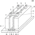
By Fig. 1~Figure 16, embodiments of the present invention 1 are described.Fig. 1 means the oblique view of the structure of semiconductor apparatus mould 100.
As shown in Figure 1, in semiconductor apparatus mould 100, semiconductor element (not shown) has with next resin-sealed P side packing unit 21 and the N side packing unit 22 of the resins such as silicon or epoxy, and on P side packing unit 21 and N side packing unit 22 first type surface with the heating panel 4 at metal, the vertical mode of first type surface of the heating panel 3 of metal is configured.
The end edge portion that P side packing unit 21 and N side packing unit 22 are configured to heating panel 3 is configured in cellular installation portion 50 clampings of the guide rail shape on the first type surface of heating panel 4 and fixes.
That is, cellular installation portion 50 becomes such structure: utilize long limit along heating panel 4 across interval and 2 rectangular materials that extend are concurrently 1 pair of guide rail shape structure, clamp the long side end edge portion of heating panel 3 in the gap of guide rail.
P side packing unit 21, with the long limit of a side opposition side of being held under the arm by unit installation portion 50 folder in, the first main electrode terminal 5, the second main electrode terminal 6 and signal terminal 13 are given prominence to from being configured as the side of rectangular-shaped resin-encapsulated 15, in N side packing unit 22 and a long limit side opposition side of being held under the arm by unit installation portion 50 folder, the first main electrode terminal 7, the second main electrode terminal 8 and signal terminal 13 are given prominence to from the side of resin-encapsulated 15.
P side packing unit 21 and N side packing unit 22 form respectively a circuit unit in semiconductor apparatus mould, but the configuration of main electrode terminal is different, by being configured to make heating panel 3 opposite each other, the first main electrode terminal being configured to is separately relative with the second main electrode terminal.
And the second main electrode terminal 6 and the first main electrode terminal 7 are configured to connecting elements 9 by conductivity each other electrically and mechanical connection.In addition, the first main electrode terminal 5, the second main electrode terminal 8 and signal terminal 13 also connect the so-called external equipment of power supply or electric equipment, control circuit respectively, but diagram is omitted.
Then,, by Fig. 2, the circuit structure of semiconductor apparatus mould 100 is described.Fig. 2 means the circuit diagram of three-phase inverter IV, and three-phase inverter IV consists of 3 inverter IV1~IV3.Inverter IV1 possesses: the IGBT being connected in series between the power line P that supply voltage VDD is provided and the power line N being connected with earthing potential (insulated gate bipolar transistor (insulated gate bipolar transistor): below, be sometimes simply called transistor) T1L and T1U; And the sustained diode 1L and the D1U that are connected with transistor T 1L and the inverse parallel of T1U difference.Moreover the connected node of transistor T 1L and T1U becomes U and exports mutually.
Inverter IV2 is also same formation, possesses: the transistor T 2L and the T2U that between power line P-N, are connected in series; And the sustained diode 2L and the D2U that are connected with transistor T 2L and the inverse parallel of T2U difference, the connected node of transistor T 2L and T2U becomes V and exports mutually.
Inverter IV3 possesses: the transistor T 3L and the T3U that between power line P-N, are connected in series; And the sustained diode 3L and the D3U that are connected with transistor T 3L and the inverse parallel of T3U difference, the connected node of transistor T 3L and T3U becomes W and exports mutually.
In addition in figure, in the transistor T 1L and T1U of inverter IV1, emitter, collector electrode, grid are represented with E, C, G respectively.
So, in the situation that establishing semiconductor apparatus mould 100 and being an inverter circuit, by combining 3 semiconductor apparatus moulds 100, the three-phase inverter IV shown in pie graph 2.
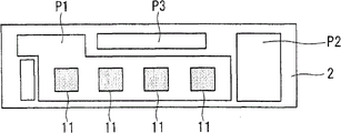
Then,, by Fig. 3~Fig. 5, the internal structure of semiconductor apparatus mould 100 is described.Fig. 3 is the figure showing omit resin-encapsulated 15 when resin-encapsulated 15 sides are watched P side packing unit 21.
On the first type surface of heating panel 3, be equipped with circuit substrate 2, on the conductive pattern P1 of the elongated shape forming on the first type surface of circuit substrate 2, each length that forms two one side is semiconductor element 1a and the 1b that 2~5mm and thickness are 0.06~0.25mm, adds up to 4 configured in series.
By using silicon carbide semiconductor device, can access the semiconductor apparatus mould of more small-sized when using silicon semiconductor element and superior for heat resistance.
In the structure shown in Fig. 3, use IGBT1a as semiconductor element 1a, and use SBD1b as semiconductor element 1b.In addition by Fig. 2, describe,, transistor T 1U and sustained diode 1U correspond respectively to IGBT1a and SBD1b, but in the example of Fig. 3, become two circuit structures that are connected in parallel separately.
In addition, above-mentioned is an example, and the kind of semiconductor element is not limited to above-mentioned semiconductor element, in addition about number, not only can each but also can be a plurality of, according to the goods specification of obtained electric current, voltage etc., select kind, number, combination and carried also can.In addition, by by parts generalization, can cutting down cost.
Connection to the conductive pattern P1 of IGBT1a and SBD1b, to make the electrode (if IGBT is collector electrode, if diode is negative pole) of its rear side engage to be connected with conductive pattern P1 by the grafting material 11 (not shown) of the scolder with high temperature scolding tin etc. or conductivity adhesives etc.
In addition, the electrode of the upper surface side of IGBT1a and SBD1b is (if IGBT is emitter, if diode is anodal), be configured to make the upper surface across IGBT1a and SBD1b by the Wiring member 10 of the thickness 0.3~1.5mm that for example copper or its alloy material form of the metal with good conductivity, and the grafting material 11 of the scolder by high temperature scolding tin etc. or conductive adhesive etc. engages with the upper surface of element.
At this, as grafting material 11, when using high temperature scolding tin, adopt and take the more than 175 ℃ stable on heating soldering tin material that has that Sn (tin) is main component.In addition, as grafting material 11, when using conductive adhesive, use the silver nano-grain cream of the silver-colored particle (silver nano-grain) of for example using organic molecular film covering diameter 2~30nm, by it be coated to IGBT1a and SBD1b upper surface and make thereon Wiring member 10 across, by sintering, can form conductive coefficient 20~90W/mK and there are 175 ℃ of above stable on heating junction surfaces.
In addition, end edge portion at conductive pattern P1 has also engaged the first main electrode terminal 5, opposition side in the bearing of trend of conductive pattern P1 and the side that engages with the first main electrode terminal 5, dispose independently conductive pattern P2, at this conductive pattern P2, engage and have Wiring member 10, and joint there is the second main electrode terminal 6.
At this, the first main electrode terminal 5 and the second main electrode terminal 6 by the metal with good conductivity for example copper or its alloy material form, its thickness is 0.3~1.5mm, the length on long limit is 5~20mm.
In addition, at the first main electrode terminal 5, the second main electrode terminal 6 and Wiring member 10, be provided with through hole TH, wherein fill up grafting material 11.By adopting this structure, the surface of the first main electrode terminal 5, the second main electrode terminal 6 and Wiring member 10 engages with opposed by grafting material 11, and by grafting material 11, also engage with the internal face of through hole TH, therefore can access the junction surface that reliability is higher.Moreover, be located at the through hole TH of the first main electrode terminal 5 and the second main electrode terminal 6, in the example of Fig. 3, there is respectively a place, but be not limited to this.
In addition, be provided with concurrently independently conductive pattern P3 with the bearing of trend of conductive pattern P1, at this conductive pattern P3, engage and to have signal terminal 13, and with the grid of IGBT1a between with going between, 14 engage.The metal wire of lead-in wire 14 use aluminium etc. forms, and can utilize wire-bonded or ultrasonic wave to engage and through crimping, engage, also can utilize conductor plate and utilize grafting material 11 to engage.
At this, the engaging of electrode of the joint of IGBT1a, the SBD1b of grafting material 11 and joint, the second main electrode terminal 6 and the 10 couples of conductive pattern P2 of Wiring member of 5 couples of conductive pattern P1 of the first main electrode terminal and Wiring member 10 and the upper surface side of IGBT1a and SBD1b will be utilized, while engaging with grafting material 11, or while engaging with conductive adhesive, can they all be engaged through common heat treatment step simultaneously, therefore can seek to improve productivity.
In addition, employing is not directly connected to the second main electrode terminal 6 main electrode of IGBT1a and SBD1b, and after being connected to for the time being conductive pattern P2, the structure being electrically connected to the main electrode of IGBT1a and SBD1b via Wiring member 10 therefore can prevent the moment useless to semiconductor element effect when the welding of main electrode terminal front end described later or when resin-sealed.
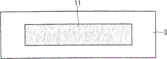
As shown in Figure 3, a first type surface at circuit substrate 2 is formed with conductive pattern P1~P3, roughly whole face at another first type surface of opposition side is formed with conductive pattern (not shown), this conductive pattern engages with the first type surface of heating panel 3, plays the effect that the heat of semiconductor element generation is transmitted and dispelled the heat to heating panel 3.
At this, heating panel 3 consists of aluminium, aluminium alloy, copper or the copper alloy of thickness 0.8~4mm, in order to ensure thermal capacity, has the long limit size longer than the length on the long limit of circuit substrate 2.
Moreover the long side end edge portion of heating panel 3 is formed on cellular installation portion 50 clampings of the guide rail shape structure on the first type surface of heating panel 4, the first type surface of heating panel 3 is vertically placed in the first type surface of heating panel 4 thus.
At this, heating panel 4 consists of aluminium, aluminium alloy, copper or the copper alloy of thickness 0.8~4mm, in order to ensure thermal capacity, has the long limit size longer than the length on the long limit of circuit substrate 2.
In addition, as described later, when welding main electrode terminal front end, utilize the local welding of arc discharge, so-called precision (micro) welding, the heat now producing, can dispel the heat by heating panel 3 and 4.Therefore, can prevent that the grafting material 11 that the joint of each several part is used from applying hot situation more than fusing point, and can prevent that the quality at the junction surface that softening, the melting of grafting material 11 cause from declining.
In addition, also can fin be set in the rear side (with the main surface side that is provided with a side opposition side of heating panel 3) of heating panel 4.Can further improve thermal diffusivity thus, but also can be according to the caloric value of semiconductor element, in addition, according to the occupation mode of semiconductor apparatus mould 100 or installment state determine no use it.
In addition, replace fin and arrange cooling fan come forced air cooling also can, also can force by water-cooled cooling.These methods are effective in the action of high temperature action fields to guaranteeing semiconductor apparatus mould 100.
Although illustrate in Fig. 3, but the joint of heating panel 3 has on the first type surface of a side of circuit substrate 2, be formed with the circuit substrate 2 that engages the state of IGBT1a, SBD1b, the first main electrode terminal 5, the second main electrode terminal 6 and Wiring member 10 is carried out to resin-sealed resin-encapsulated 15 (Fig. 1).In addition, the back side of heating panel 3 (with the first type surface that engages a side opposition side of circuit substrate 2) side is exposed.
The resin material of resin-encapsulated 15 is to take the resin that silicones or epoxy resin is main component, after bond semiconductor element ゃ Wiring member 10, guarantee insulating properties, and by the first main electrode terminal 5, the fixing maintenance of the second main electrode terminal 6, guarantee the durability engaging with circuit substrate 2.Moreover resin-sealed method adopts joint (bonding) method of for example using molding box, is shaped by the heating of 80~150 ℃.
Then, the structure of N side packing unit 22 is described.Fig. 4 is the figure showing omit resin-encapsulated 15 when resin-encapsulated 15 sides are watched N side packing unit 22.
Compare with the P side packing unit 21 shown in Fig. 3, N side packing unit 22 adopts line symmetrical structure for the imaginary line of setting between two encapsulation, becomes the opposed structure in the back side of heating panel 3 each other.This is to improving the cooling capacity of semiconductor apparatus mould 100 and realizing the effective structure of stable action that each encapsulates the semiconductor element comprising.
For the identical structure in P side packing unit 21 with shown in Fig. 3, mark identical Reference numeral, and the repetitive description thereof will be omitted.But in N side packing unit 22, the first main electrode terminal 7 engages with the end edge portion of conductive pattern P1, at the conductive pattern P2 with engaging a side opposition side of the first main electrode terminal 7, engage and have Wiring member 10, and joint there is the second main electrode terminal 8.
At this, the first main electrode terminal 7 and the second main electrode terminal 8 by the metal with good conductivity for example copper or its alloy material form, its thickness is 0.3~1.5mm.
In addition, at the first main electrode terminal 7, the second main electrode terminal 8 and Wiring member 10, be provided with through hole TH, wherein fill up grafting material 11.By adopting this structure, the surface of the first main electrode terminal 7, the second main electrode terminal 8 and Wiring member 10, by grafting material 11, engage with opposed, and also engage with the internal face of through hole TH by grafting material 11, therefore can access the junction surface that reliability is high.In addition, be located at the through hole TH of the first main electrode terminal 7 and the second main electrode terminal 8, in the example of Fig. 3, have respectively a place, but be not limited to this.
In addition, be provided with concurrently independently conductive pattern P3 with the bearing of trend of conductive pattern P1, at this conductive pattern P3, engage and to have signal terminal 13, and with the grid of IGBT1a between with going between, 14 engage.
Although illustrate in Fig. 4, but at the joint of heating panel 3, have on the first type surface of a side of circuit substrate 2, be formed with the circuit substrate 2 that engages the state of IGBT1a, SBD1b, the first main electrode terminal 7, the second main electrode terminal 8 and Wiring member 10 is carried out to resin-sealed resin-encapsulated 15 (Fig. 1).In addition, the back side of heating panel 3 (with the first type surface that engages a side opposition side of circuit substrate 2) side is exposed.
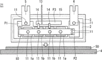
The facing view that cuts open of A-A line in Fig. 3 and Fig. 4 then, is shown at Fig. 5.As shown in Figure 5, between the second main electrode terminal 6 of P side packing unit 21 and the first main electrode terminal 7 of N side packing unit 22, be inserted with the connecting elements 9 of conductivity.
So, circuit substrate 2, IGBT1a, SBD1b and Wiring member 10 are resin-sealed in resin-encapsulated 15, but the first main electrode terminal 5,7 and the second main electrode terminal 6,8, and 2~15mm in the length on its long limit is outstanding from resin-encapsulated 15.Moreover the front end of each outstanding main electrode terminal is also uneven, and as shown in Figures 3 and 4, the recessed and irregular shape of tool of the central portion that becomes minor face.
By making such shape, when being soldered to connecting elements 9, the second main electrode terminal 6 and the first main electrode terminal 7 can prevent that weld part from contacting with each other.
At this, if the direction of the minor face along each main electrode terminal is called to Width, the recess of concaveconvex shape and the size of protuberance, when the width that the width of main electrode terminal is made as to A (mm), recess is made as X (mm), sets and become the relation that meets X >=0.4A.
So, the reason of setting the size of concaveconvex shape is: in the situation that the width of recess is narrower, when the second main electrode terminal 6 and the first main electrode terminal 7 are soldered to connecting elements 9, prevent the situation that adjacent weld part contacts with each other or likely engage.
If weld part is engaged with each other, the shape of weld part can not become the stable shape of semi-spherical shape roughly and become unsettled shape, likely reduces reliability.On the other hand, for semiconductor apparatus mould 100, require miniaturization, lightweight, cannot infinitely expand main electrode terminal width, if also consider the reliability raising at junction surface and guaranteeing of quality of item, preferably meet above-mentioned relation.
Moreover if the width of recess is wide, the narrowed width of protuberance, not only hinders weld job but also reduce bond strength, so the upper limit of the width of recess is preferably 0.5 times of left and right of the width of protuberance.
At this, shown in Fig. 6 by utilizing the local welding of arc discharge the second main electrode terminal 6 and the first main electrode terminal 7 to be engaged to the cutaway view of the state of connecting elements 9.Resin-encapsulated 15 P side packing unit 21 and N side packing unit 22 afterwards will be formed, be installed to the cellular installation portion 50 being located on heating panel 4, after riveting with forcing press etc., connecting elements 9 is inserted between the second main electrode terminals 6 and the first main electrode terminal 7, become the state shown in Fig. 5.
At this, connecting elements 9 has along the both ends of the direction on long limit to the shape of equidirectional general curved 90 degree, and the leading section of crooked front end becomes and has the concavo-convex shape identical with main electrode terminal.In addition, if the direction of the minor face along connecting elements 9 is called to Width, the width of connecting elements 9 is set as the length identical with the width of the second main electrode terminal 6 and the first main electrode terminal 7, and the size of recess and protuberance is also identical with the second main electrode terminal 6 and the first main electrode terminal 7.By making such structure, can be easy to assemble and weld.
When connecting elements 9 is inserted between the second main electrode terminal 6 and the first main electrode terminal 7, so that the leading section of the second main electrode terminal 6, the first main electrode terminal 7 mode consistent with the leading section of the crooked front end of connecting elements 9 inserted.
Then, by utilizing the local welding of arc discharge, weld the leading section of the second main electrode terminal 6 and the first main electrode terminal 7 and the leading section of connecting elements 9.By the heat of arc discharge, front end fusing each other, forms roughly hemispheric weld part BL.
At this, the Breadth Maximum that becomes weld part BL has 1.1 times of above big or small structures than the width of the protuberance of the leading section of the second main electrode terminal 6 before engaging and the first main electrode terminal 7.The reliability at junction surface can be improved thus, and quality of item can be improved.
For this reason, by Fig. 7, describe.Shown in Fig. 7, with transverse axis, get the bond strength result of the test when engaging width (Breadth Maximum of weld part BL) and getting fracture strength (N) with respect to ratio, the longitudinal axis of the width of the protuberance of main electrode terminal.
By Fig. 7, can be judged by making the Breadth Maximum of weld part BL become the more than 1.1 times of width of the protuberance of main electrode terminal, make fracture strength surpass 10N (newton), there is required bond strength.Fracture strength from the ratio of transverse axis surpass 1 near raise rapidly, but ratio is less than at 1.1 o'clock, is difficult to obtain sufficient bond strength.
In addition, this width of 1.1 times refers to and can guarantee with least energy the width of reliability at the junction surface of electrode this structure to be called to minimum connected structure.Then, by adopting minimum connected structure, can cut down production cost, and can realize miniaturization, lightweight.
In addition, as shown in Figure 7: if the Breadth Maximum of weld part BL is the more than 1.1 times of width of the protuberance of main electrode terminal, can obtain required bond strength, but, from the relation of explanation and the width recess of main electrode terminal before, on thinking, be limited to 2 times of left and right of width of the protuberance of main electrode terminal.
At this, welding method can be used electron beam welding or Laser Welding to fetch the local welding that replaces utilizing arc discharge, in this case, also can form roughly hemispheric weld part BL.
In addition, by P side packing unit 21 and N side packing unit 22 after forming resin-encapsulated 15, be installed on cellular installation portion 50 and riveted joint after, utilize the local welding of arc discharge, therefore the sealed resin of semiconductor element covers, and the arc discharge of expanding with skirt shape can not cause damage to semiconductor element.This when using electron beam welding or laser welding too.
By utilizing connecting elements 9 to engage the second main electrode terminal 6 and the first main electrode terminal 7, P side packing unit 21 and N side packing unit 22 are electrically connected to, form 1 group of inverter circuit shown in Fig. 2.
< manufacture method >
Then, by order, represent Fig. 8~Figure 16 of manufacturing process, the manufacture method of semiconductor apparatus mould 100 is described.In addition, take in the following description the manufacture method of the P side packing unit 21 shown in Fig. 3 describes as example.
First, in the operation shown in Fig. 8, prepare to be formed with the circuit substrate 2 of conductive pattern P1~P3, the area configurations grafting material 11 that is equipped with semiconductor element on conductive pattern P1 on a first type surface.
Then,, in the operation shown in Fig. 9, prepare IGBT1a and SBD1b, and be equipped on the region that disposes grafting material 11.
Then, in the operation shown in Figure 10, on upper surface, conductive pattern P1 and the P2 of IGBT1a and SBD1b, engage respectively the region of the first main electrode terminal 5 and the second main electrode terminal 6 and the area configurations grafting material 11 of the joint Wiring member 10 on conductive pattern P2.
Then, in the operation shown in Figure 11, prepare Wiring member 10 and the first main electrode terminal 5 and the second main electrode terminal 6, and be equipped on the region of configuration grafting material 11.Thereafter, heater circuit substrate 2 under the temperature conditions of regulation, makes grafting material 11 solidify (or sclerosis), thus by each structural engagement (affixed) to circuit substrate 2.
Then,, in the operation shown in Figure 12, prepare heating panel 3, the area configurations grafting material 11 of the bonded circuitry substrate 2 on a first type surface.
Then, in the operation shown in Figure 13, the circuit substrate 2 that semiconductor element has been installed is equipped on to the region of configuration grafting material 11, under the temperature conditions of regulation, heat, make grafting material 11 solidify (or sclerosis), thus circuit substrate 2 is engaged to (affixed) to heating panel 3.
Then, in the operation shown in Figure 14, due to the grid of IGBT1a is electrically connected to conductive pattern P3, by wire-bonded or ultrasonic wave 14 the joint that engages to go between.In addition, signal terminal 13 also engages to be connected to conductive pattern P3 by wire-bonded or ultrasonic wave.For convenience's sake, the structure completing to this operation is called to circuit unit.
Then,, in the operation shown in Figure 15, the circuit substrate 2 that semiconductor element is installed is carried out resin-sealed on heating panel 3.Concrete encapsulating method is to cover circuit substrate 2 completely, and the molding box outstanding in the end that makes the first main electrode terminal 5 and the second main electrode terminal 6 embeds heating panel 3, to importing the sealing resin of Thermocurable in this molding box, at 80~150 ℃, heat and make resin solidification, shaping resin encapsulation 15.Thus, complete P side packing unit 21 and N side packing unit 22.
Then, in the operation shown in Figure 16, prepare heating panel 4, by the long limit of the heating panel 3 in P side packing unit 21 and N side packing unit 22 (the long limit of a side of main electrode terminal is not set), insert the gap of the guide rail of each cellular installation portion 50, utilize forcing press by forming the rectangular material riveted joint of guide rail, be fixed thus.Thereby, be fixed into the first type surface that makes the first type surface of heating panel 3 vertically be placed in heating panel 4.
Thereafter, between the second main electrode terminal 6 and the first main electrode terminal 7, insert connecting elements 9, by utilizing the local welding of arc discharge, by the leading section welding of the leading section of the second main electrode terminal 6 and the first main electrode terminal 7 and connecting elements 9, form thus the weld part BL shown in Fig. 6, complete semiconductor apparatus mould 100.
< effect >
As described above in semiconductor apparatus mould 100, when engaging the second main electrode terminal 6 and the first main electrode terminal 7 and connecting elements 9, do not use the grafting material (for example soldering tin material) being formed by the metal different from being engaged material (main electrode terminal), and make mother metal, the second main electrode terminal 6, the first main electrode terminal 7 and connecting elements 9 melt and solidify, thereby make metallic atom coupled to each other and engage, therefore can not produce the mismatch (miss match) of the coefficient of linear expansion of mother metal and grafting material.
; under the semiconductor apparatus mould requirement very severe environment that more than 225 ℃ variations in temperature is larger in temperature difference (Δ T), use; if the material that therefore has like that different coefficient of linear expansion by soldering tin material engages; the mismatch because of the coefficient of linear expansion with mother metal produces larger thermal strain or thermal stress at junction surface, likely produces be full of cracks.Moreover, thin thickness to the 0.3~1.5mm of main electrode terminal, once therefore produce be full of cracks, be full of cracks is likely development just.
But, in the present invention, by use, utilized the local welding of arc discharge, within several msec~several seconds, finish welding and can suppress the generation of thermal strain, and can not produce the mismatch of coefficient of linear expansion, and can suppress to result from the generation of be full of cracks of the difference of coefficient of linear expansion.Therefore, can access the junction surface that reliability is high.
In addition.As grafting material 11, use has 175 ℃ of above stable on heating soldering tin material or silver nano-grain cream, also can in the junction surface of resin-encapsulated 15 inside, guarantee more than 175 ℃ thermal endurances thus, and as semiconductor element, use silicon carbide semiconductor device, meanwhile can improve semiconductor apparatus mould 100 own reliability and quality of item.
In addition,, owing to adopting the cellular installation portion 50 that the long side end edge portion of heating panel 3 is sandwiched to the guide rail shape structure on the first type surface that is formed on heating panel 4, the fixing structure of heating panel 4 thus, so can be reliably and carry out securely the fixing of heating panel 4.
In addition, by employing, make the first type surface of heating panel 3 vertically be positioned at the structure of the first type surface of heating panel 4, can coordinate and from the side of resin-encapsulated 15, make the outstanding structure of main electrode terminal and seek miniaturization, lightweight.
In addition, by combination heating panel 3 and 4, can increase thermal capacity, and by making the back side of heating panel 3 be exposed to air, in the back side of heating panel 3, also can dispel the heat, can improve the thermal diffusivity of semiconductor apparatus mould 100 semiconductor element of heating when driving, even also can move normally at higher temperature.
< execution mode 2>
Then,, by Figure 17, the structure of the semiconductor apparatus mould 200 of embodiments of the present invention 2 is described.In addition, for the structure identical with the semiconductor apparatus mould 100 shown in Fig. 3 and Fig. 4, mark identical Reference numeral, omit the explanation of its repetition.
Figure 17 is the facing view that cuts open of the part same with the semiconductor apparatus mould 100 shown in Fig. 3 and Fig. 4, and semiconductor element 1b joins on circuit substrate 2, and heating panel 3 use grafting materials 12 join on the first type surface of heating panel 4.
Then, P lateral circuit and N lateral circuit are surrounded by housing 18, fill the encapsulant 16 of insulating properties and resin-sealed P lateral circuit and N lateral circuit in the framework consisting of housing 18 and heating panel 4.Housing 18 consists of the insulating material of PPS, PBT, SPS and epoxy etc., and its thickness is 0.5~1.5mm.
So, in semiconductor apparatus mould 200, be configured to P lateral circuit and N lateral circuit by jointly resin-sealed, because resin-encapsulated is one, for the purpose of facilitating, P lateral circuit be called to P lateral circuit unit 210, N lateral circuit is called to N lateral circuit unit 220.
The second main electrode terminal 6A of P lateral circuit unit 210 and the first main electrode terminal 7A of N lateral circuit unit 220 be shaped as that upper end is bent twice and section is Z-shaped shape.That is, have for the time being to the vertical direction of the first type surface with main electrode terminal crookedly and form the first zigzag part, then turn back and form the structure of the second zigzag part to the parallel direction of the first type surface with main electrode terminal.Moreover first and second zigzag part bends to the angle a little less than right angle, become thus the section shape of Z-shaped shape.This is also identical in the first main electrode terminal 7A, and also identical in the first main electrode terminal (not shown) of P lateral circuit unit 210 and the second main electrode terminal (not shown) of N lateral circuit unit 220.
In addition, the connecting elements 9A between the second main electrode terminal 6A and the first main electrode terminal 7A, bends to the angle a little less than 90 degree along the both ends of growing the direction on limit to identical direction, and has the curved section shape of central portion.
By adopting this structure, can in zigzag part, absorb the thermal stress, the thermal strain that in the junction surface of each main electrode terminal, produce, therefore can further improve reliability and quality of item.
That is, when semiconductor apparatus mould 200 is used under severe environment, such as cold use, special result in the situation such as vehicle-mounted use.
In addition, by the shape of each main electrode terminal is made to curved shape, can shorten electrode length, and can realize further miniaturization, lightweight.
That is, this is because the density that the material of main electrode terminal is copper or copper alloy is about 8933kg/m
3, the material of main electrode terminal shared weight ratio in the full weight amount of semiconductor apparatus mould is to be only second to the cause that heating panel is larger.Moreover the bending machining of each main electrode terminal is to utilize forcing press etc., by transmitting successively metal pattern high efficiency, carry out.
In addition, in semiconductor apparatus mould 200, heating panel 3 utilizes grafting material 12 to join on the first type surface of heating panel 4, but grafting material 12 is used the conductive adhesive of the scolder with more than 175 ℃ stable on heating high temperature scolding tin etc. of take that Sn is main component or silver nano-grain cream etc.Thus, semiconductor apparatus mould 200 also can be guaranteed durability under more than 175 ℃ high temperature, therefore in addition the pyroconductivity of grafting material 12 is 20~90W/mK, can be in heating panel 4 heat of semiconductor element generation during heat conduction action efficiently by heating panel 3.
Moreover, with the semiconductor apparatus mould 100 shown in Fig. 3 similarly, also can rivet the structure that fixes heating panel 3 for range site installation portion 50.On the contrary, in semiconductor apparatus mould 100, with semiconductor apparatus mould 200 similarly, the structure of utilizing grafting material 12 to engage heating panels 3 also can.
In the manufacture of semiconductor apparatus mould 200, on a first type surface of heating panel 4, utilize grafting material 12 to engage behind the side on long limit (the long limit of a side of main electrode terminal is not set) of heating panel 3 of P lateral circuit unit 210 and N lateral circuit unit 220, utilize bonding agent (not shown) housing of bottomless uncovered 18 to be fixed on the first type surface of heating panel 4, to surround P lateral circuit unit 210 and N lateral circuit unit 220.
The framework that by housing 18 and heating panel 4 formed in, as encapsulant 16 fill for example silicon gel or epoxy resin thereafter.
So, by employing, framework is set and the structure of packing matcrial 16, can simplify manufacturing process, in addition, the P lateral circuit unit 210 and the N lateral circuit unit 220 that with encapsulant 16, cover except the leading section of main electrode terminal, can prevent that the part beyond junction surface produces unfavorable condition when welding thus.
Then, between the second outstanding main electrode terminal 6 of encapsulant 16 and the first main electrode terminal 7, inserting connecting elements 9, by utilizing the local welding of arc discharge, leading section welding by the leading section of the second main electrode terminal 6 and the first main electrode terminal 7 and connecting elements 9, completes semiconductor apparatus mould 200 thus.
In addition, also can replace the second main electrode terminal 6, the first main electrode terminal 7 and connecting elements 9 in the semiconductor apparatus mould 100 of execution mode 1 and use the second main electrode terminal 6A, the first main electrode terminal 7A and connecting elements 9A.
< execution mode 3>
Then,, by Figure 18 and Figure 19, the structure of the semiconductor apparatus mould 300 of embodiments of the present invention 3 is described.In addition, for the structure identical with the semiconductor apparatus mould 100 shown in Fig. 3 and Fig. 4, mark identical Reference numeral, omit the explanation of its repetition.
Figure 18 is the facing view that cuts open of the part same with the semiconductor apparatus mould 100 shown in Fig. 3 and Fig. 4, and semiconductor element 1b joins on circuit substrate 2, and heating panel 3 utilizes grafting material 12 to join on the first type surface of heating panel 4.
Then, be configured to above P lateral circuit and N lateral circuit, dispose and comprise the control substrate 19 generating the control circuit of the control signal of the grid of not shown IGBT1a, comprise this control substrate 19, P lateral circuit and N lateral circuit are all accommodated in resin-encapsulated 17.
So, in semiconductor apparatus mould 300, be configured to P lateral circuit and N lateral circuit by jointly resin-sealed, because resin-encapsulated is one, for the purpose of facilitating, P lateral circuit be called to P lateral circuit unit 210, N lateral circuit is called to N lateral circuit unit 220.
As shown in figure 19, P lateral circuit unit 210 and N lateral circuit unit 220 are so that the relative mode of circuit substrate 2 is each other equipped on heating panel 4, and the back side of each heating panel 3 is configured in a side of resin-encapsulated 17 exposes.
Each heating panel 3 of P lateral circuit unit 210 and N lateral circuit unit 220, the side on long limit (the long limit of a side of main electrode terminal is not set) joins the step difference of establishing along the end edge portion of the long side of heating panel 4 to by grafting material 12.Grafting material 12 is used the conductive adhesive of the scolder with more than 175 ℃ stable on heating high temperature scolding tin etc. of take that Sn is main component or silver nano-grain cream etc.
The second main electrode terminal 6 of P lateral circuit unit 210 and the first main electrode terminal 7 of N lateral circuit unit 220, perforation is configured in the control substrate 19 of top and extends, by utilizing the local welding of arc discharge, the leading section welding of the connecting elements 9 that the leading section of the second main electrode terminal 6 and the first main electrode terminal 7 inserts between with it, forms weld part BL.
In addition, the first main electrode terminal 5 (not shown) of P lateral circuit unit 210 and the second main electrode terminal 8 (not shown) of N lateral circuit unit 220, perforation is configured in the control substrate 19 of top and extends, and leading section is separately by utilizing the local welding of arc discharge to be soldered to outside terminal 30 and 31. Outside terminal 30 and 31 end are outstanding from the upper surface of resin-encapsulated 17, are connected respectively with power supply or electric equipment etc.
Figure 19 omits resin-encapsulated 17 P lateral circuit unit 210 and the figure that shows when circuit substrate 2 one sides are watched P lateral circuit unit 210.In addition, the B-B line in Figure 19 to cut open facing view corresponding with Figure 18.
As shown in figure 19, the signal terminal 13 being connected with conductive pattern P3 extends towards the control substrate 19 of top, is configured to by the control circuit (not shown) with controlling substrate 19 and is connected control signal is provided.
In addition, the first main electrode terminal 7 (not shown) of the second main electrode terminal 6 of P lateral circuit unit 210 and N lateral circuit unit 220 is connected with not shown connecting elements 9, but connecting elements 9 is also connected with outside terminal 32, the end of outside terminal 32 is configured to from the upper surface of resin-encapsulated 17 outstanding.In addition, outside terminal 32 can be also the structure arranging integratedly with connecting elements 9.
So, in semiconductor apparatus mould 300, the back side of the heating panel separately 3 of P lateral circuit unit 210 and N lateral circuit unit 220, in the side of resin-encapsulated 17, expose, also expose at the back side of heating panel 4, therefore 3 faces (radiating surface) relevant to heat radiation are exposed to outside, thereby can obtain higher thermal diffusivity.Thus, can bring into play fully the characteristic that semiconductor element has.
Moreover, with the cooling radiating surface exposing of naturally cooling mode also can, but to each radiating surface install air cooling fan also can, water cooling fan is installed in addition and also can.
In the manufacture of semiconductor apparatus mould 300, after being provided with at the end edge portion along long side on the first type surface of heating panel 4 of step difference and engaging the side on long limit (the long limit of a side of main electrode terminal is not set) of heating panel 3 of P lateral circuit unit 210 and N lateral circuit unit 220 with grafting material 12, substrate 19 is controlled in configuration, so that each main electrode terminal connects, be located at the peristome of controlling substrate 19, and make the signal terminal separately 13 of P lateral circuit unit 210 and N lateral circuit unit 220 be connected to the control circuit of controlling the regulation on substrate 19.At this moment, be for example configured to, by soldering, signal terminal 13 be connected to control circuit, support and control substrate 19 also can thus.
Then, between the second main electrode terminal 6 and the first main electrode terminal 7, insert connecting elements 9, by utilizing the local welding of arc discharge, by the leading section welding of the leading section of the second main electrode terminal 6 and the first main electrode terminal 7 and connecting elements 9.At this moment, in the situation that utilize the connecting elements 9 becoming one with outside terminal 32, can save the time that outside terminal 32 is soldered to connecting elements 9.
In addition, outside terminal 30 and 32 is by utilizing the local welding of arc discharge to be respectively welded to the first main electrode terminal 5 of P lateral circuit unit 210 and the second main electrode terminal 8 (not shown) of N lateral circuit unit 220.In addition, the shape of outside terminal 30 and end 32, that be connected with the first main electrode terminal 5 and the second main electrode terminal 8 respectively, for the end irregular shape of same tool with the first main electrode terminal 5 and the second main electrode terminal 8 both can.
Then, so that the part beyond the leading section of outside terminal 30~32 is formed resin-encapsulated 17 by complete resin-sealed mode.
Concrete encapsulating method is on heating panel 4, the molding box of the outside terminal 30~32 beyond P lateral circuit unit 210, N lateral circuit unit 220 and leading section is surrounded in configuration, to the sealing resin that imports Thermocurable in this molding box, in 80~150 ℃, heat and make resin solidification, shaping resin encapsulates 17.
By adopting this structure, the junction of each main electrode terminal and circuit substrate 2 is also covered by resin-encapsulated 17, can improve reliability and quality of item.
Moreover, due to by utilizing the shaping in batch of metal pattern to carry out resin-sealed operation, in the situations such as a large amount of manufactures, become at a low price and the very good structure of productivity.
In addition, also can replace the second main electrode terminal 6, the first main electrode terminal 7 and connecting elements 9 in the semiconductor apparatus mould 300 of execution mode 3 and use and use in the semiconductor apparatus mould 200 of execution mode 2, the second main electrode terminal 6A, the first main electrode terminal 7A and connecting elements 9A.
< variation 1>
Shown in Figure 20 by the structure around of the semiconductor apparatus mould 100 shown in resin-case 30 encirclement Fig. 1.In addition, for the identical structure of semiconductor apparatus mould 100 with shown in Fig. 1, mark identical Reference numeral, omit the explanation of its repetition.
As shown in figure 20, on the first type surface of heating panel 4, to surround the mode of P side packing unit 21 and N side packing unit 22, be fixed with the resin-case 40 of bottomless uncovered.
Resin-case 40 has in the both sides of the direction along long limit the base portion 41 and 42 that the mode to extend laterally respectively arranges.
Then, be configured in base portion 41, from connecting elements 9, extend outside terminal ACT, and base portion 42 extend with the outside terminal PT of the first main electrode terminal 5 welding of P side packing unit 21 and with the outer terminal NT of the second main electrode terminal 8 welding of N side packing unit 22.
In addition, the first main electrode terminal 5 of P side packing unit 21 and the second main electrode terminal 8 of the welding of outside terminal PT and N side packing unit 22 and the welding of outside terminal NT, also used the local welding that has utilized arc discharge.
Moreover, outside terminal PT and NT's, the shape of the end being connected with each the first main electrode terminal 5 and the second main electrode terminal 8, for the end irregular shape of same tool with the first main electrode terminal 5 and the second main electrode terminal 8 both can.
So, by configuring resin-case 40 to surround the mode of P side packing unit 21 and N side packing unit 22, semiconductor apparatus mould 100 becomes more firmly structure as a unit.
In addition,, by outside terminal ACT, PT and NT are set, there is the effect being connected that can easily carry out with power supply or electric equipment etc.
< variation 2>
In semiconductor apparatus mould 100~300 described above, just, among the three-phase inverter IV shown in Fig. 2, the situation with two circuit units that form inverter IV1 is illustrated.So, by forming a module with a plurality of circuit units, improve assembleability.
But, in the inverter of 1 group, only use the transistor of a current potential side and the circuit unit composition module of fly-wheel diode also can.In the case, by combining 6 semiconductor apparatus moulds, the three-phase inverter IV shown in pie graph 2.
In addition, be not 1 group of inverter but 3 groups of inverters, that is, with the mode composition module of all circuit units of comprising the three-phase inverter IV shown in pie graph 2, also can.In the case, only use 1 three-phase inverter IV shown in semiconductor apparatus mould pie graph 2.From the viewpoint of assembleability, a side who is configured for all circuit units that form three-phase inverter on 1 heating panel 4 is comparatively favourable.
Description of reference numerals
1a IGBT; 1b SBD; 2 circuit substrates; 3,4 heating panels; 5,7,7A the first main electrode terminal; 6,6A, 8 second main electrode terminals; 9,9A connecting elements; 10 Wiring members; 11,12 grafting materials; 15,17 resin-encapsulated; 16 encapsulants; 18 housings; P1~P3 conductive pattern.
Claims (12)
1. a semiconductor apparatus mould, comprising:
Have be equipped with semiconductor element circuit substrate,
Carry described circuit substrate the first heating panel,
And at least one circuit unit of the main electrode terminal being electrically connected to the main electrode of described semiconductor element;
Carry the second heating panel of described at least one circuit unit,
Wherein said the first heating panel so that its first type surface mode vertical with the first type surface of described the second heating panel be equipped on described the second heating panel,
One end of described main electrode terminal is connected with described circuit substrate, outstanding from described the first heating panel to direction extension and the other end of the described major surfaces in parallel with described the first heating panel,
Described main electrode terminal consists of tabular component, and the described other end has central portion becomes the concaveconvex shape that recess and its both sides become protuberance,
Described at least one circuit unit is a plurality of circuit units,
Described a plurality of circuit unit so that the parallel mode of described the first heating panel be separately equipped on described the second heating panel,
Between described a plurality of circuit units, possess and connect main electrode terminal connecting elements each other described in each,
Described connecting elements engages by weld part with described main electrode terminal.
2. semiconductor apparatus mould as claimed in claim 1, wherein,
Described connecting elements consists of tabular component, and the shape of end has shape, the size identical with the described concaveconvex shape of described main electrode terminal, and it is relative with the protuberance of described main electrode terminal that the protuberance of described connecting elements is configured to.
3. semiconductor apparatus mould as claimed in claim 1, wherein,
The junction surface of described connecting elements and described main electrode terminal forms hemispheric weld part, and its Breadth Maximum is the more than 1.1 times of width of the protuberance of described main electrode terminal.
4. semiconductor apparatus mould as claimed in claim 1, wherein,
The width of the recess of described main electrode terminal is the more than 0.4 times of terminal width.
5. semiconductor apparatus mould as claimed in claim 1, wherein,
Described circuit substrate has conductive pattern on its first type surface,
Described one end of described main electrode terminal is connected with described conductive pattern,
Described at least one circuit unit possesses the described main electrode of the described semiconductor element of electrical connection and the Wiring member of described conductive pattern.
6. semiconductor apparatus mould as claimed in claim 1, wherein,
Described at least one circuit unit has and is configured on described the first heating panel and the resin-encapsulated forming to cover the mode of described circuit substrate completely,
The described other end of described main electrode terminal is outstanding from the side of described resin-encapsulated.
7. semiconductor apparatus mould as claimed in claim 1, wherein,
Possess housing, this housing is equipped on described the second heating panel, and described at least one circuit unit except the described other end that surrounds described main electrode terminal is around,
In the framework being formed by described housing and described the second heating panel, be filled with the encapsulant of insulating properties.
8. semiconductor apparatus mould as claimed in claim 1, wherein,
So that the mode outside becoming with the back side of carrying a side opposition side of described circuit substrate, described the first heating panel makes the end face of a side opposition side outstanding with described main electrode terminal engage with the end edge portion of described the second heating panel by grafting material,
Described at least one circuit unit possesses resin-encapsulated, resin-sealed except the described back side of described the first heating panel, whole described at least one circuit unit.
9. semiconductor apparatus mould as claimed in claim 1, wherein,
Described main electrode terminal consists of tabular component, has that described another is distolateral crooked and form the first zigzag part to the direction vertical with its first type surface for the time being, and then to turning back with the parallel direction of first type surface, forms the section shape of the Z-shaped shape of the second zigzag part.
10. semiconductor apparatus mould as claimed in claim 1, wherein,
By making the end edge portion of a side opposition side outstanding with described main electrode terminal be sandwiched in the cellular installation portion that is arranged on the guide rail shape on described the second heating panel, fixing described the first heating panel.
11. semiconductor apparatus moulds as claimed in claim 1, wherein,
Utilize grafting material, make described the first heating panel with the end joined of the outstanding side opposition side of described main electrode terminal to described the second heating panel.
12. semiconductor apparatus moulds as claimed in claim 1, wherein,
Described semiconductor element is silicon carbide semiconductor device.
Applications Claiming Priority (2)
| Application Number | Priority Date | Filing Date | Title |
|---|---|---|---|
| JP2010014912A JP5213884B2 (en) | 2010-01-27 | 2010-01-27 | Semiconductor device module |
| JP2010-014912 | 2010-01-27 |
Publications (2)
| Publication Number | Publication Date |
|---|---|
| CN102136472A CN102136472A (en) | 2011-07-27 |
| CN102136472B true CN102136472B (en) | 2014-02-26 |
Family
ID=44296204
Family Applications (1)
| Application Number | Title | Priority Date | Filing Date |
|---|---|---|---|
| CN201010571357.7A Active CN102136472B (en) | 2010-01-27 | 2010-11-22 | Semiconductor apparatus module |
Country Status (5)
| Country | Link |
|---|---|
| US (1) | US8610263B2 (en) |
| JP (1) | JP5213884B2 (en) |
| KR (1) | KR101173927B1 (en) |
| CN (1) | CN102136472B (en) |
| DE (1) | DE102011003205B4 (en) |
Families Citing this family (13)
| Publication number | Priority date | Publication date | Assignee | Title |
|---|---|---|---|---|
| JP2012145489A (en) * | 2011-01-13 | 2012-08-02 | Sankei Engineering:Kk | Manufacturing method of inspection probe |
| JP2013258387A (en) * | 2012-05-15 | 2013-12-26 | Rohm Co Ltd | Power-module semiconductor device |
| US10308856B1 (en) | 2013-03-15 | 2019-06-04 | The Research Foundation For The State University Of New York | Pastes for thermal, electrical and mechanical bonding |
| DE112013007721B4 (en) * | 2013-12-27 | 2020-07-23 | Mitsubishi Electric Corporation | Semiconductor device |
| EP3100301B1 (en) * | 2014-01-30 | 2019-11-06 | Cree Fayetteville, Inc. | Low profile, highly configurable, current sharing paralleled wide band gap power device power module |
| TWM496091U (en) * | 2014-03-26 | 2015-02-21 | Leadray Energy Co Ltd | LED with silicon substrate and LED lamp |
| JP5862702B2 (en) * | 2014-05-07 | 2016-02-16 | トヨタ自動車株式会社 | Three-phase inverter module |
| CN108140631B (en) * | 2015-09-28 | 2021-02-05 | 三菱电机株式会社 | Semiconductor device with a plurality of semiconductor chips |
| US10334715B2 (en) * | 2015-12-18 | 2019-06-25 | Intel Corporation | Systems, methods and devices for a package securing system |
| JP6759784B2 (en) | 2016-07-12 | 2020-09-23 | 三菱電機株式会社 | Semiconductor module |
| JP6764389B2 (en) * | 2017-10-12 | 2020-09-30 | 矢崎総業株式会社 | Semiconductor module unit |
| JP7159609B2 (en) * | 2018-05-15 | 2022-10-25 | 株式会社デンソー | semiconductor equipment |
| JP7059970B2 (en) * | 2019-03-11 | 2022-04-26 | 株式会社デンソー | Semiconductor device |
Family Cites Families (19)
| Publication number | Priority date | Publication date | Assignee | Title |
|---|---|---|---|---|
| JPS53140369A (en) | 1977-05-14 | 1978-12-07 | Matsushita Electric Works Ltd | Production of metal plate covered with multi-layer synthetic resins |
| JPS545569A (en) | 1977-06-15 | 1979-01-17 | Mitsubishi Electric Corp | Hybrid integrated circuit device |
| JPS62130547A (en) | 1985-12-02 | 1987-06-12 | Mitsubishi Electric Corp | Semiconductor device |
| JPH03101156A (en) | 1989-09-13 | 1991-04-25 | Fujitsu Ltd | Semiconductor device |
| JPH03117846A (en) | 1989-09-29 | 1991-05-20 | Toshiba Corp | Air conditioner |
| JP3021896B2 (en) | 1991-11-15 | 2000-03-15 | 日本インター株式会社 | Method for manufacturing composite semiconductor device |
| JPH05315517A (en) * | 1992-05-12 | 1993-11-26 | Nec Corp | Semiconductor device |
| JPH0794669A (en) * | 1993-09-20 | 1995-04-07 | Toshiba Corp | Semiconductor package module |
| JP3525832B2 (en) | 1999-11-24 | 2004-05-10 | 株式会社デンソー | Semiconductor device |
| JP4019989B2 (en) | 2003-03-26 | 2007-12-12 | 株式会社デンソー | Semiconductor device |
| JP2005142520A (en) | 2003-10-14 | 2005-06-02 | Sumitomo Electric Ind Ltd | Power module |
| KR100586698B1 (en) * | 2003-12-23 | 2006-06-08 | 삼성전자주식회사 | Semiconductor Module having semiconductor chip package which is vertically mounted on module board |
| JP2006019465A (en) * | 2004-07-01 | 2006-01-19 | Mitsui Chemicals Inc | Semiconductor package and its manufacturing method |
| JP4567570B2 (en) * | 2005-10-17 | 2010-10-20 | 三菱電機株式会社 | Power converter |
| US7923842B2 (en) * | 2006-03-16 | 2011-04-12 | Skyworks Solutions, Inc. | GaAs integrated circuit device and method of attaching same |
| JP4878520B2 (en) | 2006-08-09 | 2012-02-15 | 本田技研工業株式会社 | Semiconductor device |
| JP5227532B2 (en) * | 2007-04-02 | 2013-07-03 | 日立オートモティブシステムズ株式会社 | Semiconductor module for inverter circuit |
| JP4667476B2 (en) * | 2008-02-18 | 2011-04-13 | 三菱電機株式会社 | Electrical component connection method and connection structure, and power conversion device using the connection structure |
| JP4937951B2 (en) * | 2008-03-25 | 2012-05-23 | 三菱電機株式会社 | Power semiconductor device and manufacturing method thereof |
-
2010
- 2010-01-27 JP JP2010014912A patent/JP5213884B2/en active Active
- 2010-10-20 US US12/908,327 patent/US8610263B2/en active Active
- 2010-11-22 CN CN201010571357.7A patent/CN102136472B/en active Active
-
2011
- 2011-01-24 KR KR1020110006628A patent/KR101173927B1/en active IP Right Grant
- 2011-01-26 DE DE102011003205.3A patent/DE102011003205B4/en active Active
Non-Patent Citations (2)
| Title |
|---|
| JP特开2008-259267A 2008.10.23 |
| JP特开2009-231672A 2009.10.08 |
Also Published As
| Publication number | Publication date |
|---|---|
| JP2011155088A (en) | 2011-08-11 |
| DE102011003205B4 (en) | 2014-01-16 |
| US8610263B2 (en) | 2013-12-17 |
| JP5213884B2 (en) | 2013-06-19 |
| DE102011003205A1 (en) | 2011-07-28 |
| KR101173927B1 (en) | 2012-08-16 |
| KR20110088404A (en) | 2011-08-03 |
| CN102136472A (en) | 2011-07-27 |
| US20110180809A1 (en) | 2011-07-28 |
Similar Documents
| Publication | Publication Date | Title |
|---|---|---|
| CN102136472B (en) | Semiconductor apparatus module | |
| JP6234630B2 (en) | Power module | |
| JP7204770B2 (en) | Double-sided cooling power module and manufacturing method thereof | |
| US9379083B2 (en) | Semiconductor device and method for manufacturing semiconductor device | |
| CN105122446B (en) | Semiconductor device, the assemble method of semiconductor device, member for semiconductor device and single-bit module | |
| CN103370788B (en) | Semiconductor device and manufacture method thereof | |
| JP5863602B2 (en) | Power semiconductor device | |
| CN104170085A (en) | Semiconductor device | |
| JP5895220B2 (en) | Manufacturing method of semiconductor device | |
| JP5659938B2 (en) | Semiconductor unit and semiconductor device using the same | |
| JP2011009410A (en) | Semiconductor module | |
| CN102903693A (en) | Power device package module and manufacturing method thereof | |
| CN105531817A (en) | Semiconductor module unit and semiconductor module | |
| KR102228945B1 (en) | Semiconductor package and method of fabricating the same | |
| CN207381382U (en) | Electric power electronic module and power electric component package substrate | |
| JP6945418B2 (en) | Semiconductor devices and manufacturing methods for semiconductor devices | |
| JP4620566B2 (en) | Semiconductor device and manufacturing method thereof | |
| JP2015023226A (en) | Wide gap semiconductor device | |
| CN103296019A (en) | Semiconductor device and method for manufacturing semiconductor device | |
| CN112331632A (en) | Semiconductor device with a plurality of semiconductor chips | |
| JP2012227455A (en) | Semiconductor module | |
| CN112992818B (en) | Power device and manufacturing method thereof | |
| JP2012238737A (en) | Semiconductor module and manufacturing method therefor | |
| JP6647187B2 (en) | Power module and method of manufacturing the same | |
| JP5465313B2 (en) | Semiconductor device module |
Legal Events
| Date | Code | Title | Description |
|---|---|---|---|
| C06 | Publication | ||
| PB01 | Publication | ||
| C10 | Entry into substantive examination | ||
| SE01 | Entry into force of request for substantive examination | ||
| C14 | Grant of patent or utility model | ||
| GR01 | Patent grant |