CN101966650A - Numerical control gantry vertical combined machine tool - Google Patents
Numerical control gantry vertical combined machine tool Download PDFInfo
- Publication number
- CN101966650A CN101966650A CN2010102842379A CN201010284237A CN101966650A CN 101966650 A CN101966650 A CN 101966650A CN 2010102842379 A CN2010102842379 A CN 2010102842379A CN 201010284237 A CN201010284237 A CN 201010284237A CN 101966650 A CN101966650 A CN 101966650A
- Authority
- CN
- China
- Prior art keywords
- saddle
- screw mandrel
- drive motors
- ram
- column
- Prior art date
- Legal status (The legal status is an assumption and is not a legal conclusion. Google has not performed a legal analysis and makes no representation as to the accuracy of the status listed.)
- Pending
Links
Images


Landscapes
- Machine Tool Units (AREA)
Abstract
The invention relates to a numerical control machine tool, in particular to a numerical control gantry vertical combined machine tool which mainly solves the problem that the machine tool structure can not meet the requirements for high-efficiency precision finishing because milling and boring heads, grinding heads and other devices arranged on a cross beam of the traditional machine tool in the prior art can not make vertical precise feed motions. The numerical control gantry vertical combined machine tool comprises a base (1), a workbench (2) and upright columns (3). The numerical control gantry vertical combined machine tool is characterized in that the upright columns (3) are movably connected with a composite cross beam (4) by an upright column guide or are fixedly connected with the composite cross beam (4) by fasteners, the composite cross beam (4) is movably connected with more than two saddles (503) by a cross beam guide or is fixedly connected with more than two saddles (503) by fasteners, and the saddles are movably connected with a spindle device (5) by a ram guide; and the base, the upright columns, the composite cross beam and the spindle device are respectively provided with a screw rod driving device, and all the screw rod driving devices are connected with an electrical numerical control device.
Description
Technical field
The present invention relates to a kind of Digit Control Machine Tool, especially relate to the vertical combined machine of a kind of numerical control gantry.
Background technology
The numerical control gantry lathe mainly is made of lathe bed, workbench, left and right pillar, crossbeam, saddle, main speed reduction box, console, electric control box and driving control device.Can finish mill, multiple operation processing such as brill, hinge, boring, be applicable to thick, the fine finishining of the large and medium-sized part of every profession and trade.Chinese patent discloses a kind of numerical control gantry heavy-duty machine for machining, milling, boring, planing and grinding, and (publication number: CN 101502933A), it is made up of lathe bed, carriage, composite pillar, crossbeam, back timber, rotary motive power head, chuck, tailstock, main drive gear, bistrique, milling and boring heads, planing tool frame, turning tool rest, electric control system etc.; By line slideway guiding, carriage is finished the reciprocating motion of carriage by main drive motor, main drive gear, gear, tooth bar to carriage, moves back and forth velocity interval: O.02-60000mm/min on lathe bed; Two composite pillars are connected with securing member respectively with the lathe bed two sides; Back timber is connected with securing member with two composite pillar upper surfaces; Crossbeam is installed in respectively on the guide rail of composite pillar both sides, utilizes two driven by servomotor of lifting one's head, and drives leading screw and rotates, and moves up and down thereby finish crossbeam; Milling and boring heads on the crossbeam, turning tool rest are used driven by servomotor respectively, drive leading screw and rotate, and finish milling and boring heads, turning tool rest traverse feed; Bistrique on the crossbeam, planing tool frame are used driven by servomotor respectively, drive leading screw and rotate, and finish bistrique, the traverse feed of planing tool frame; Bistrique on two composite pillars, planing tool frame are installed in respectively on the guide rail of composite pillar, use driven by servomotor respectively, drive leading screw and rotate, and finish bistrique, the motion of planing tool frame bottom and top feed.But the milling and boring heads that this lathe is provided with on crossbeam, tool holder, bistrique, planing tool frame can not carry out precision feeding motion up and down, and machine tool structure can not be suitable for the high-efficiency and precision process requirements.
Summary of the invention
The present invention provides the vertical combined machine of a kind of numerical control gantry, its milling and boring heads, tool holder, bistrique, planing tool frame that mainly is solution existing in prior technology lathe is provided with on crossbeam can not carry out precision feeding motion up and down, and machine tool structure can not be suitable for the problem of high-efficiency and precision process requirements.
The invention provides the upright combined machine that crouches of a kind of numerical control gantry, lathe under the situation of a clamping of workpiece, can be realized the efficient composite energy-saving Precision Machining of two above operations by novel accurate vertical or horizontal main axis device more than two is housed.
Above-mentioned technical problem of the present invention is mainly solved by following technical proposals:
The vertical combined machine of numerical control gantry of the present invention, comprise base, workbench, column, described column flexibly connects by the column guide rail or is fixedly connected with composite transverse beam by securing member, composite transverse beam flexibly connects by beam guideway or is fixedly connected with saddle more than 2 by securing member, and saddle is connected with main shaft device by ram gib; Base, column, crossbeam, main shaft device are provided with screw rod driving device, and screw rod driving device all connects electric numerical control device.Each vertical spindle device can connect drive unit by a rhizoid bar respectively, and drive unit can be crisscross arranged at the two ends of composite transverse beam respectively.Because the drive unit branch is located at the two ends of composite transverse beam, therefore shared space is less.Electric numerical control device can be controlled composite transverse beam moving on column, also can control vertical spindle device moving on composite transverse beam.
The vertical spindle device can move on crossbeam up and down; Workpiece is installed on the workbench and moves forward and backward, and plural main shaft device carries out efficient, compound, energy-conservation, the Precision Machining of two above operations to workpiece.Crossbeam top can be provided with back timber, or crossbeam and back timber are made one.
As preferably, described composite transverse beam is movably connected on two root posts by the column guide rail; Be provided with the column screw mandrel in the column, screw mandrel is connected with the column drive motors, and the column drive motors is fixed on column one end by column drive motors seat, and the column screw mandrel shaft block is fixed on the other end of column, and the column screw mandrel flexibly connects crossbeam by the crossbeam nut seat.Like this, crossbeam just can rely on the stand column and beam screw mandrel to move up and down on column, makes the vertical spindle device adapt to the high and low position of workpiece.
As preferably, described composite transverse beam is connected with left saddle, right saddle by beam guideway, also be provided with the left saddle screw mandrel that is connected with left saddle, right saddle respectively, right saddle screw mandrel on the composite transverse beam, left side saddle screw mandrel is connected with left saddle drive motors at an end of crossbeam, right saddle screw mandrel is connected with right saddle drive motors at an end of composite transverse beam, left and right saddle drive motors is fixed on the composite transverse beam by left saddle motor cabinet, right saddle motor cabinet respectively, and the other end of left and right saddle screw mandrel is respectively equipped with right saddle bearing block, left saddle bearing block.Left and right saddle drive motors is located at the two ends of composite transverse beam respectively, drives left and right saddle screw mandrel by left and right saddle drive motors respectively and rotates, thereby drive laterally moving of vertical spindle device.Be equiped with bearing in left side saddle bearing block, the right saddle bearing block, can make things convenient for the screw mandrel rotation.
As preferably, described left saddle and right saddle are provided with compensating cylinder, and the compensating cylinder upper end is connected with the compensating cylinder support, and the compensating cylinder support is fixed on the ram of main shaft device, and the crossbeam saddle flexibly connects ram by ram gib.Smoothness when compensating cylinder can improve the vertical feed of vertical and high-speed main shaft device helps lathe and realizes Precision Machining.
As preferably, described vertical spindle device is the vertical and high-speed main shaft device, it includes saddle, be provided with screw mandrel in the saddle, screw mandrel is connected with drive motors, drive motors is fixed on the saddle by the drive motors seat, be provided with bearing block in the saddle, bearing block is provided with bearing, and screw mandrel is connected with ram, be fixed with knife striking cylinder by the knife striking cylinder support on the vertical ram, knife striking cylinder is used for automatically or rapid changing knife, and the knife striking cylinder below is provided with high-speed main spindle, and main shaft is connected with synchronous pulley by synchronous band, synchronous pulley is connected on the main motor, and main motor is fixed on the ram by main motor cabinet.Drive motors can drive screw mandrel and be rotated, and moves up and down thereby drive whole ram; Main motor-driven high-speed main spindle carries out high speed and precision processing.
As preferably, described vertical spindle device is vertical low speed main shaft device, it includes saddle, be provided with vertical screw mandrel in the saddle, screw mandrel is connected with drive motors, drive motors is fixed on the saddle by the drive motors seat, be provided with bearing block in the saddle, bearing block is provided with bearing, and screw mandrel is connected with vertical ram, be fixed with knife striking cylinder by the knife striking cylinder support on the ram, knife striking cylinder is used for automatically or rapid changing knife, and the knife striking cylinder below is provided with quick main shaft, and main shaft is connected with synchronous pulley by synchronous band, synchronous pulley is connected on the main motor by gear reduction box, and main motor is fixed on the vertical ram by main motor cabinet.Drive motors can drive screw mandrel and be rotated, and moves up and down thereby drive whole ram.Main motor-driven low speed main shaft slows down and increases knuckling and can process.
As preferably, described vertical spindle device is vertical grinding spindle device, and it includes saddle, is provided with screw mandrel in the saddle, screw mandrel is connected with drive motors, drive motors is fixed on the saddle by the drive motors seat, is provided with bearing block in the saddle, and bearing block is provided with bearing, screw mandrel is connected with ram, ram is provided with mount pad, and mount pad is provided with can be to the grinding head body of either direction rotation in same vertical plane, and the grinding head body two ends are respectively equipped with main motor and emery wheel.Drive motors can drive screw mandrel and be rotated, and moves up and down thereby drive whole mounting seat.After main motor-driven emery wheel rotates, can carry out cross grinding or the processing of peripheral accurate grinding to workpiece.
As preferably, described vertical spindle device is the vertical and high-speed electric main shaft device, it includes saddle, be provided with screw mandrel in the saddle, screw mandrel is connected with drive motors, and drive motors is fixed on the saddle by the drive motors seat, be provided with bearing block in the saddle, bearing block is provided with bearing, and screw mandrel is connected with ram, is connected with electric main shaft on the ram.Drive motors can drive screw mandrel and be rotated, and moves up and down thereby drive whole electric main shaft.After main motor-driven electricity main shaft rotates, can process the high speed and precision that workpiece carries out more than the 15000rmp.
As preferably, described workbench is movably connected on the base by guide rail, and workbench is connected with the workbench screw mandrel, and the workbench screw mandrel is connected on the servomotor, and servomotor is fixed on the base by the servomotor seat.After the driven by servomotor, can drive workbench by the workbench screw mandrel and move, thereby can adjust the position of workpiece.
Therefore the present invention is being equipped with novel accurate vertical spindle device more than two on the lathe, and clamping of workpiece just can be realized the efficient Compound Machining of two above operations, can reduce the repeated clamping error and improve the workpiece machining accuracy; Configuration high-speed main shaft device or high-speed electric main shaft device are realized high-speed and high-efficiency processing, and configuration is slowed down and increased the cutting of turning round of low speed main shaft device realization heavy load and energy-conservation processing, and configuration grinding spindle device is realized cross grinding or peripheral grinding Precision Machining.
Description of drawings
Accompanying drawing 1 is a kind of structural representation of the present invention;
Accompanying drawing 2 is a kind of plan structure schematic diagrames of Fig. 1;
Accompanying drawing 3 is a kind of side structure schematic diagrames of Fig. 1;
Accompanying drawing 4 is a kind of structural representations of composite transverse beam of the present invention;
Accompanying drawing 5 is a kind of structural representations of vertical and high-speed main shaft device of the present invention;
Accompanying drawing 6 is a kind of side structure schematic diagrames of Fig. 5;
Accompanying drawing 7 is a kind of structural representations of the vertical low speed main shaft device of the present invention;
Accompanying drawing 8 is a kind of side structure signals of Fig. 7;
Accompanying drawing 9 is a kind of structural representations of the vertical grinding spindle device of the present invention;
Accompanying drawing 10 is a kind of side structure signals of Fig. 9;
Accompanying drawing 11 is a kind of structural representations of vertical and high-speed electric main shaft device of the present invention;
Accompanying drawing 12 is a kind of side structure signals of Figure 11.
Accompanying drawing 13 is a kind of structural representations of the embodiment of the invention 5;
Accompanying drawing 14 is a kind of plan structure schematic diagrames of Figure 13;
Accompanying drawing 15 is a kind of side structure schematic diagrames of Figure 13;
Parts among the figure, position and numbering: base 1, workbench 2, column 3, column screw mandrel 301, column drive motors 302, column drive motors seat 303, column screw mandrel shaft block 304, crossbeam nut seat 305, composite transverse beam 4, guide rail 401, left side saddle screw mandrel 402, right saddle screw mandrel 403, left side saddle drive motors 404, right saddle drive motors 405, left side saddle motor cabinet 406, right saddle motor cabinet 407, right saddle bearing block 408, left side saddle bearing block 409, vertical spindle device 5, left side saddle 501, right saddle 502, saddle 503, screw mandrel 504, drive motors 505, drive motors seat 506, bearing block 507, bearing 508, ram 509, knife striking cylinder support 510, knife striking cylinder 511, high-speed main spindle 512, be with 513 synchronously, synchronous pulley 514, main motor 515, main motor cabinet 516, compensating cylinder 517, compensating cylinder support 518, vertical pressing plate 519, gear reduction box 520, mount pad 521, grinding head body 522, emery wheel 523, electricity main shaft 524, low speed main shaft 525, workbench screw mandrel 6, servomotor 7, servomotor seat 8.
The specific embodiment
Below by embodiment, and in conjunction with the accompanying drawings, technical scheme of the present invention is described in further detail.
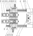
Embodiment 1: the vertical combined machine of this routine numerical control gantry, as Fig. 1, Fig. 2, Fig. 3, there is one to comprise base 1, be connected with workbench 2 by guide rail on the base, workbench is connected with workbench screw mandrel 6, the workbench screw mandrel is connected on the servomotor 7, and servomotor is fixed on the base by servomotor seat 8.Also be provided with two root posts 3 on the base, column is fixedly connected with composite transverse beam 4, and composite transverse beam is provided with 2 vertical spindle devices 5 and electric numerical control device.
As Fig. 4, composite transverse beam is provided with guide rail 401, flexibly connect the vertical spindle device on the guide rail, be respectively equipped with left saddle 501 on the vertical spindle device, right saddle 502, composite transverse beam is provided with respectively and left saddle, the left saddle screw mandrel 402 that right saddle connects, right saddle screw mandrel 403, left side saddle screw mandrel is connected with left saddle drive motors 404 at the left end of composite transverse beam, right saddle screw mandrel is connected with right saddle drive motors 405 at the right-hand member of composite transverse beam, a left side, right saddle drive motors is respectively by left saddle motor cabinet 406, right saddle motor cabinet 407 is fixed on the composite transverse beam, a left side, the other end of right saddle screw mandrel is respectively equipped with right saddle bearing block 408, left side saddle bearing block 409, a left side, be provided with bearing in the right saddle bearing block.
As Fig. 5, Fig. 6, vertical spindle device 5 is the vertical and high-speed main shaft device, and it includes saddle 503, and saddle is provided with compensating cylinder 517, and the compensating cylinder upper end is connected on the compensating cylinder support 518, also is connected with vertical pressing plate 519 on the saddle.Be provided with screw mandrel 504 in the saddle, screw mandrel is connected with drive motors 505, drive motors is fixed on the saddle by drive motors seat 506, be provided with bearing block 507 in the saddle, be provided with bearing 508 between bearing block and the screw mandrel, screw mandrel is connected with ram 509, be fixed with knife striking cylinder 511 by knife striking cylinder support 510 on the ram, the knife striking cylinder below is provided with high-speed main spindle 512, high-speed main spindle is by being with 513 to be connected with synchronous pulley 514 synchronously, synchronous pulley is connected on the main motor 515, and main motor is fixed on the ram by main motor cabinet 516.
During use, drive 6 rotations of workbench screw mandrel, thereby adjust the position of workbench 2, make the workpiece working position aim at vertical spindle device 5 by servomotor 7.Drive left saddle screw mandrel 402,403 rotations of right saddle screw mandrel by left saddle drive motors 404, right saddle drive motors 405, thereby adjust the lateral attitude of vertical spindle device.Again by screw mandrel 504 adjust the vertical spindle heads the position, after main motor 515 started, by synchronous pulley 514, synchronously with 513 transmission, high-speed main spindle 512 began to rotate, high-speed main spindle is installed cutter, the cutter that connects thereon can be processed workpiece.
Embodiment 2: the vertical combined machine of this routine numerical control gantry, as Fig. 1, Fig. 2, Fig. 3, there is one to comprise base 1, be connected with workbench 2 by guide rail on the base, workbench is connected with workbench screw mandrel 6, the workbench screw mandrel is connected on the servomotor 7, and servomotor is fixed on the base by servomotor seat 8.Also be provided with two root posts 3 on the base, column is fixedly connected with composite transverse beam 4, and composite transverse beam is provided with 2 vertical spindle devices 5 and electric numerical control device.
As Fig. 4, composite transverse beam is provided with guide rail 401, flexibly connect the vertical spindle device on the guide rail, be respectively equipped with left saddle 501 on the vertical spindle device, right saddle 502, composite transverse beam is provided with respectively and left saddle, the left saddle screw mandrel 402 that right saddle connects, right saddle screw mandrel 403, left side saddle screw mandrel is connected with left saddle drive motors 404 at the left end of composite transverse beam, right saddle screw mandrel is connected with right saddle drive motors 405 at the right-hand member of composite transverse beam, a left side, right saddle drive motors is respectively by left saddle motor cabinet 406, right saddle motor cabinet 407 is fixed on the composite transverse beam, a left side, the other end of right saddle screw mandrel is respectively equipped with right saddle bearing block 408, left side saddle bearing block 409, a left side, be provided with bearing in the right saddle bearing block.
As Fig. 7, Fig. 8, vertical spindle device 5 is vertical low speed main shaft device, and it includes saddle 503, and saddle is provided with compensating cylinder 517, and the compensating cylinder upper end is connected on the compensating cylinder support 518, also is connected with vertical pressing plate 519 on the saddle.Be provided with screw mandrel 504 in the saddle, screw mandrel is connected with drive motors 505, drive motors is fixed on the saddle by drive motors seat 506, be provided with bearing block 507 in the saddle, be provided with bearing 508 between bearing block and the screw mandrel, screw mandrel is connected with ram 509, be fixed with knife striking cylinder 511 by knife striking cylinder support 510 on the ram, the knife striking cylinder below is provided with low speed main shaft 525, low speed main shaft 525 is by being with 513 to be connected with synchronous pulley 514 synchronously, synchronous pulley is connected on main motor 515 by gear reduction box 520, and main motor is fixed on the ram by main motor cabinet 516.
During use, drive 6 rotations of workbench screw mandrel, thereby adjust the position of workbench 2, make the workpiece working position aim at vertical spindle device 5 by servomotor 7.Drive left saddle screw mandrel 402,403 rotations of right saddle screw mandrel by left saddle drive motors 404, right saddle drive motors 405, thereby adjust the lateral attitude of vertical spindle device.Adjust the position of vertical spindle head again by screw mandrel 504, after main motor 515 starts, retarded motion through gear reduction box 520, make synchronous pulley 514 slowly run, through synchronously with 513 transmission, low speed main shaft 525 begins to slowly run, and low speed main shaft 525 is installed cutter, and the cutter that connects thereon can be processed workpiece.
Embodiment 3: the vertical combined machine of this routine numerical control gantry, as Fig. 1, Fig. 2, Fig. 3, there is one to comprise base 1, be connected with workbench 2 by guide rail on the base, workbench is connected with workbench screw mandrel 6, the workbench screw mandrel is connected on the servomotor 7, and servomotor is fixed on the base by servomotor seat 8.Also be provided with two root posts 3 on the base, column is fixedly connected with composite transverse beam 4, and composite transverse beam is provided with 2 vertical spindle devices 5 and electric numerical control device.
As Fig. 4, composite transverse beam is provided with guide rail 401, flexibly connect the vertical spindle device on the guide rail, be respectively equipped with left saddle 501 on the vertical spindle device, right saddle 502, composite transverse beam is provided with respectively and left saddle, the left saddle screw mandrel 402 that right saddle connects, right saddle screw mandrel 403, left side saddle screw mandrel is connected with left saddle drive motors 404 at the left end of composite transverse beam, right saddle screw mandrel is connected with right saddle drive motors 405 at the right-hand member of composite transverse beam, a left side, right saddle drive motors is respectively by left saddle motor cabinet 406, right saddle motor cabinet 407 is fixed on the composite transverse beam, a left side, the other end of right saddle screw mandrel is respectively equipped with right saddle bearing block 408, left side saddle bearing block 409, a left side, be provided with bearing in the right saddle bearing block.
As Fig. 9, Figure 10, vertical spindle device 5 is vertical grinding spindle device, and it includes saddle 503, and saddle 503 is provided with compensating cylinder 517, and the compensating cylinder upper end is connected on the compensating cylinder support 518, also is connected with vertical pressing plate 519 on the saddle.Be provided with screw mandrel 504 in the saddle, screw mandrel is connected with drive motors 505, drive motors is fixed on the saddle by drive motors seat 506, be provided with bearing block 507 in the saddle, be provided with bearing 508 between bearing block and the screw mandrel, screw mandrel is connected with mount pad 521, and mount pad is provided with can be to the grinding head body 522 of either direction rotation in same vertical plane, and the grinding head body two ends are respectively equipped with main motor 515 and emery wheel 523.
During use, drive 6 rotations of workbench screw mandrel, thereby adjust the position of workbench 2, make the workpiece working position aim at vertical spindle device 5 by servomotor 7.Drive left saddle screw mandrel 402,403 rotations of right saddle screw mandrel by left saddle drive motors 404, right saddle drive motors 405, thereby adjust the lateral attitude of vertical spindle device.Adjusted the position of grinding head body 522 again by screw mandrel 504, after main motor 515 started, by the transmission of grinding head body 522, emery wheel 523 began to rotate, thereby workpiece is carried out grinding.
Embodiment 4: the vertical combined machine of this routine numerical control gantry, as Figure 13, Figure 14, Figure 15, there is one to comprise base 1, be connected with workbench 2 by guide rail on the base, workbench is connected with workbench screw mandrel 6, the workbench screw mandrel is connected on the servomotor 7, and servomotor is fixed on the base by servomotor seat 8.Also be provided with two root posts 3 on the base, column is fixedly connected with composite transverse beam 4, and composite transverse beam is provided with 2 vertical spindle devices 5 and electric numerical control device.
As Fig. 4, composite transverse beam is provided with guide rail 401, flexibly connect the vertical spindle device on the guide rail, be respectively equipped with left saddle 501 on the vertical spindle device, right saddle 502, composite transverse beam is provided with respectively and left saddle, the left saddle screw mandrel 402 that right saddle connects, right saddle screw mandrel 403, left side saddle screw mandrel is connected with left saddle drive motors 404 at the left end of composite transverse beam, right saddle screw mandrel is connected with right saddle drive motors 405 at the right-hand member of composite transverse beam, a left side, right saddle drive motors is respectively by left saddle motor cabinet 406, right saddle motor cabinet 407 is fixed on the composite transverse beam, a left side, the other end of right saddle screw mandrel is respectively equipped with right saddle bearing block 408, left side saddle bearing block 409, a left side, be provided with bearing in the right saddle bearing block.
As Figure 11, Figure 12, vertical spindle device 5 is the vertical and high-speed electric main shaft device, and it includes saddle 503, and saddle 503 is provided with compensating cylinder 517, and the compensating cylinder upper end is connected on the compensating cylinder support 518, also is connected with vertical pressing plate 519 on the saddle.Be provided with screw mandrel 504 in the saddle, screw mandrel is connected with drive motors 505, and drive motors is fixed on the saddle by drive motors seat 506, is provided with bearing block 507 in the saddle, is provided with bearing 508 between bearing block and the screw mandrel, and screw mandrel is connected with electric main shaft 524.
During use, drive 6 rotations of workbench screw mandrel, thereby adjust the position of workbench 2, make the workpiece working position aim at vertical spindle device 5 by servomotor 7.Drive left saddle screw mandrel 402,403 rotations of right saddle screw mandrel by left saddle drive motors 404, right saddle drive motors 405, thereby adjust the lateral attitude of vertical spindle device.Adjusted the position of saddle 503 again by screw mandrel 504, behind the main electric motor starting, 524 pairs of workpiece of electric main shaft can be processed.
Embodiment 5: the vertical combined machine of this routine numerical control gantry, as Figure 13, Figure 14, Figure 15, there is one to comprise base 1, be connected with workbench 2 by guide rail on the base, workbench is connected with workbench screw mandrel 6, the workbench screw mandrel is connected on the servomotor 7, and servomotor is fixed on the base by servomotor seat 8.Also be provided with two root posts 3 on the base, column is connected with composite transverse beam 4 by the column guide rail, be provided with column screw mandrel 301 in the column, the column screw mandrel is connected with column drive motors 302, the column drive motors is fixed on column one end by column drive motors seat 303, column screw mandrel shaft block 304 is fixed on the other end of column, and the column screw mandrel flexibly connects crossbeam by crossbeam nut seat 305.Composite transverse beam is provided with 2 vertical spindle devices 5 and electric numerical control device.
As Fig. 4, composite transverse beam is provided with guide rail 401, flexibly connect the vertical spindle device on the guide rail, be respectively equipped with left saddle 501 on the vertical spindle device, right saddle 502, composite transverse beam is provided with respectively and left saddle, the left saddle screw mandrel 402 that right saddle connects, right saddle screw mandrel 403, left side saddle screw mandrel is connected with left saddle drive motors 404 at the left end of composite transverse beam, right saddle screw mandrel is connected with right saddle drive motors 405 at the right-hand member of composite transverse beam, a left side, right saddle drive motors is respectively by left saddle motor cabinet 406, right saddle motor cabinet 407 is fixed on the composite transverse beam, a left side, the other end of right saddle screw mandrel is respectively equipped with right saddle bearing block 408, left side saddle bearing block 409, a left side, be provided with bearing in the right saddle bearing block.
As Fig. 5, Fig. 6, vertical spindle device 5 is the vertical and high-speed main shaft device, and it includes saddle 503, and saddle is provided with compensating cylinder 517, and the compensating cylinder upper end is connected on the compensating cylinder support 518, also is connected with vertical pressing plate 519 on the saddle.Be provided with screw mandrel 504 in the saddle, screw mandrel is connected with drive motors 505, drive motors is fixed on the saddle by drive motors seat 506, be provided with bearing block 507 in the saddle, be provided with bearing 508 between bearing block and the screw mandrel, screw mandrel is connected with ram 509, be fixed with knife striking cylinder 511 by knife striking cylinder support 510 on the ram, the knife striking cylinder below is provided with main shaft 512, main shaft is by being with 513 to be connected with synchronous pulley 514 synchronously, synchronous pulley is connected on the main motor 515, and main motor is fixed on the ram by main motor cabinet 516.
During use, drive 6 rotations of workbench screw mandrel, thereby adjust the position of workbench 2, make the workpiece working position aim at vertical spindle device 5 by servomotor 7.Can drive moving up and down of composite transverse beam by column screw mandrel 301, thereby adjust moving up and down of vertical spindle device.Drive left saddle screw mandrel 402,403 rotations of right saddle screw mandrel by left saddle drive motors 404, right saddle drive motors 405 again, thereby adjust the lateral attitude of vertical spindle device.Adjusted the position of knife striking cylinders 511 again by screw mandrel 504, after main motor 515 started, by synchronous pulley 514, synchronously with 513 transmission, main shaft 512 began to rotate, and knife striking cylinder 511 is installed cutter, and the cutter that connects thereon can be processed workpiece.
The above only is specific embodiments of the invention, but architectural feature of the present invention is not limited thereto, and any those skilled in the art is in the field of the invention, and the variation of being done or modify all is encompassed among the claim of the present invention.
Claims (8)
1. vertical combined machine of numerical control gantry, comprise base (1), workbench (2), column (3), it is characterized in that described column (3) is fixedly connected with composite transverse beam (4) by the flexible connection of column guide rail or by securing member, composite transverse beam (4) flexibly connects by beam guideway or is fixedly connected with saddle (503) more than 2 by securing member, and saddle is connected with main shaft device (5) by ram gib; Base, column, composite transverse beam, main shaft device are provided with screw rod driving device, and screw rod driving device all connects electric numerical control device.
2. the vertical combined machine of numerical control gantry according to claim 1 is characterized in that described crossbeam is movably connected on two root posts by the column guide rail; Be provided with column screw mandrel (301) in the column, the column screw mandrel is connected with column drive motors (302), the column drive motors is fixed on column one end by column drive motors seat (303), column screw mandrel shaft block (304) is fixed on the other end of column, and the column screw mandrel flexibly connects crossbeam by crossbeam nut seat (305).
3. the vertical combined machine of numerical control gantry according to claim 1, it is characterized in that described composite transverse beam (4) is connected with left saddle (501) by beam guideway, right saddle (502), also be provided with on the composite transverse beam (4) respectively and left saddle, the left saddle screw mandrel (402) that right saddle connects, right saddle screw mandrel (403), left side saddle screw mandrel is connected with left saddle drive motors (404) at an end of crossbeam, right saddle screw mandrel is connected with right saddle drive motors (405) at an end of composite transverse beam, a left side, right saddle drive motors is respectively by left saddle motor cabinet (406), right saddle motor cabinet (407) is fixed on the composite transverse beam left side, the other end of right saddle screw mandrel is respectively equipped with right saddle bearing block (408), left side saddle bearing block (409).
4. the vertical combined machine of numerical control gantry according to claim 2, it is characterized in that described left saddle (501) and right saddle (502) are provided with compensating cylinder (517), the compensating cylinder upper end is connected with compensating cylinder support (518), the compensating cylinder support is fixed on the ram (509) of main shaft device, and saddle flexibly connects ram (509) by ram gib.
5. according to claim 1 or the vertical combined machine of 2 or 3 described numerical control gantries, it is characterized in that described main shaft device is the high-speed main spindle device, comprise saddle (503), saddle flexibly connects ram (509) by ram gib, be provided with screw mandrel (502) in the saddle, screw mandrel is connected with drive motors (505), drive motors is fixed on the saddle by drive motors seat (506), be provided with bearing block (507) in the saddle, be provided with bearing (508) between bearing block and the screw mandrel, screw mandrel is connected with ram (509), be fixed with knife striking cylinder (511) by knife striking cylinder support (510) on the ram, the knife striking cylinder below is provided with high-speed main spindle (512), high-speed main spindle is connected with synchronous pulley (514) by being with (513) synchronously, synchronous pulley is connected on the main motor (515), and main motor is fixed on the ram by main motor cabinet (516).
6. according to claim 1 or the vertical combined machine of 2 or 3 described numerical control gantries, it is characterized in that described main shaft device is vertical low speed main shaft device, comprise saddle (503), saddle flexibly connects ram (509) by ram gib, be provided with screw mandrel (504) in the saddle, screw mandrel is connected with drive motors (505), drive motors is fixed on the saddle by drive motors seat (506), be provided with bearing block (507) in the saddle, be provided with bearing (508) between bearing block and the screw mandrel, screw mandrel is connected with ram (509), be fixed with knife striking cylinder (511) by knife striking cylinder support (510) on the ram, the knife striking cylinder below is provided with low speed main shaft (525), the low speed main shaft is connected with synchronous pulley (514) by being with (513) synchronously, synchronous pulley is connected on the main motor (515) by gear reduction box (520), and main motor is fixed on the ram by main motor cabinet (516).
7. according to claim 1 or the vertical combined machine of 2 or 3 described numerical control gantries, it is characterized in that described main shaft device is the grinding spindle device, comprise saddle (503), saddle flexibly connects ram by ram gib, be provided with screw mandrel (504) in the saddle, screw mandrel is connected with drive motors (505), drive motors is fixed on the saddle by drive motors seat (506), be provided with bearing block (507) in the saddle, be provided with bearing (508) between bearing block and the screw mandrel, screw mandrel is connected with ram (509), ram is provided with mount pad (521), mount pad is provided with can be to the grinding head body (522) of either direction rotation in same vertical plane, and the grinding head body two ends are respectively equipped with main motor (515) and emery wheel (523).
8. according to claim 1 or the vertical combined machine of 2 or 3 described numerical control gantries, it is characterized in that described main shaft device is a high-speed electric main shaft device, comprise saddle (503), saddle flexibly connects ram by ram gib, be provided with screw mandrel (504) in the saddle, screw mandrel is connected with drive motors (505), drive motors is fixed on the saddle by drive motors seat (506), be provided with bearing block (507) in the saddle, be provided with bearing (508) between bearing block and the screw mandrel, screw mandrel is connected with ram (509), and ram is provided with electric main shaft (524).
Priority Applications (1)
| Application Number | Priority Date | Filing Date | Title |
|---|---|---|---|
| CN2010102842379A CN101966650A (en) | 2010-09-17 | 2010-09-17 | Numerical control gantry vertical combined machine tool |
Applications Claiming Priority (1)
| Application Number | Priority Date | Filing Date | Title |
|---|---|---|---|
| CN2010102842379A CN101966650A (en) | 2010-09-17 | 2010-09-17 | Numerical control gantry vertical combined machine tool |
Publications (1)
| Publication Number | Publication Date |
|---|---|
| CN101966650A true CN101966650A (en) | 2011-02-09 |
Family
ID=43545905
Family Applications (1)
| Application Number | Title | Priority Date | Filing Date |
|---|---|---|---|
| CN2010102842379A Pending CN101966650A (en) | 2010-09-17 | 2010-09-17 | Numerical control gantry vertical combined machine tool |
Country Status (1)
| Country | Link |
|---|---|
| CN (1) | CN101966650A (en) |
Cited By (19)
| Publication number | Priority date | Publication date | Assignee | Title |
|---|---|---|---|---|
| CN102416646A (en) * | 2011-10-28 | 2012-04-18 | 杭州大天数控机床有限公司 | Quartz crucible numerical control milling-grinding special machine tool |
| CN102699769A (en) * | 2011-09-21 | 2012-10-03 | 杨东佐 | Numerical control equipment |
| CN102699685A (en) * | 2012-05-28 | 2012-10-03 | 南通京鼎机械科技有限公司 | Numerical control gantry milling machine of fixed beam |
| CN102794645A (en) * | 2011-05-26 | 2012-11-28 | 李景珠 | Numerical control pinhole machining device |
| CN103591258A (en) * | 2012-08-16 | 2014-02-19 | 宜兴市灵人机械有限公司 | Large plano-grinding oil hydraulic cylinder driving end fixing device |
| CN104002292A (en) * | 2014-05-23 | 2014-08-27 | 苏州博众精工科技有限公司 | Complementary type mechanical hand device |
| CN104074942A (en) * | 2014-06-23 | 2014-10-01 | 苏州博众精工科技有限公司 | Gantry servo synchronous drive and dual screw rod single drive mechanism |
| CN104128969A (en) * | 2014-08-12 | 2014-11-05 | 临夏县祥泰工艺品有限责任公司 | Machine tool for processing carpentry girders, purlins and rafters |
| CN105290794A (en) * | 2015-10-28 | 2016-02-03 | 武汉理工大学 | Multi-axis linkage numerical control trimming and burr cleaning-up tool |
| WO2016090649A1 (en) * | 2014-12-12 | 2016-06-16 | 江苏海恒建材机械有限公司 | Milling adjusting device for processing pipe wall plane |
| CN107790750A (en) * | 2017-11-02 | 2018-03-13 | 齐齐哈尔齐机工业产品有限公司 | A kind of propeller plan processes cutter holder assembly |
| CN108372594A (en) * | 2018-04-26 | 2018-08-07 | 深圳市创世纪机械有限公司 | Double end single channel glass machine |
| CN109227318A (en) * | 2018-11-06 | 2019-01-18 | 深圳市创世纪机械有限公司 | Double-station numerical control lathe |
| CN109732351A (en) * | 2018-11-27 | 2019-05-10 | 临沂金座木业机械制造有限公司 | A kind of numerical control saw |
| CN110153712A (en) * | 2018-02-10 | 2019-08-23 | 江苏乔扬数控设备股份有限公司 | A kind of double main shaft double knife towers combined machines |
| CN110270834A (en) * | 2019-06-06 | 2019-09-24 | 高大朋 | A kind of high-precision printing machine parts machining milling bed |
| CN111300053A (en) * | 2020-03-26 | 2020-06-19 | 浙江海帝克机床有限公司 | Double-turret combined machining machine tool |
| CN112828651A (en) * | 2020-12-29 | 2021-05-25 | 蚌埠市富瑞达机床机械制造有限公司 | Impurity removing device for processing of vertical boring and milling machine |
| CN116944896A (en) * | 2023-06-30 | 2023-10-27 | 浙江能伟科技有限公司 | Numerical control gantry machine tool |
Citations (7)
| Publication number | Priority date | Publication date | Assignee | Title |
|---|---|---|---|---|
| JPS55157412A (en) * | 1979-05-24 | 1980-12-08 | Om Seisakusho:Kk | Combined machine tool |
| CN2644061Y (en) * | 2003-08-27 | 2004-09-29 | 江苏多棱数控机床股份有限公司 | Equalizer of large numerical control planomilling machine |
| CN101502933A (en) * | 2009-03-10 | 2009-08-12 | 吉林省鸿源机床制造有限责任公司 | Numerical control gantry heavy-duty machine for machining, milling, boring, planing and grinding |
| CN101700620A (en) * | 2009-11-11 | 2010-05-05 | 南京工业大学 | Large gantry coordinate numerical control milling, hobbing and grinding combined machine tool |
| CN201524905U (en) * | 2009-02-09 | 2010-07-14 | 深圳市康铖机械设备有限公司 | Small portal double main shaft drilling and milling numerically-controlled machine tool |
| CN201565779U (en) * | 2009-12-16 | 2010-09-01 | 山东鲁重数控机床股份有限公司 | Numerical-control gantry milling and drilling combined machine tool |
| CN201799851U (en) * | 2010-09-17 | 2011-04-20 | 王元庆 | Numerical-control vertical combined gantry machine tool |
-
2010
- 2010-09-17 CN CN2010102842379A patent/CN101966650A/en active Pending
Patent Citations (7)
| Publication number | Priority date | Publication date | Assignee | Title |
|---|---|---|---|---|
| JPS55157412A (en) * | 1979-05-24 | 1980-12-08 | Om Seisakusho:Kk | Combined machine tool |
| CN2644061Y (en) * | 2003-08-27 | 2004-09-29 | 江苏多棱数控机床股份有限公司 | Equalizer of large numerical control planomilling machine |
| CN201524905U (en) * | 2009-02-09 | 2010-07-14 | 深圳市康铖机械设备有限公司 | Small portal double main shaft drilling and milling numerically-controlled machine tool |
| CN101502933A (en) * | 2009-03-10 | 2009-08-12 | 吉林省鸿源机床制造有限责任公司 | Numerical control gantry heavy-duty machine for machining, milling, boring, planing and grinding |
| CN101700620A (en) * | 2009-11-11 | 2010-05-05 | 南京工业大学 | Large gantry coordinate numerical control milling, hobbing and grinding combined machine tool |
| CN201565779U (en) * | 2009-12-16 | 2010-09-01 | 山东鲁重数控机床股份有限公司 | Numerical-control gantry milling and drilling combined machine tool |
| CN201799851U (en) * | 2010-09-17 | 2011-04-20 | 王元庆 | Numerical-control vertical combined gantry machine tool |
Cited By (26)
| Publication number | Priority date | Publication date | Assignee | Title |
|---|---|---|---|---|
| CN102794645A (en) * | 2011-05-26 | 2012-11-28 | 李景珠 | Numerical control pinhole machining device |
| CN102699769A (en) * | 2011-09-21 | 2012-10-03 | 杨东佐 | Numerical control equipment |
| CN102416646A (en) * | 2011-10-28 | 2012-04-18 | 杭州大天数控机床有限公司 | Quartz crucible numerical control milling-grinding special machine tool |
| CN102699685A (en) * | 2012-05-28 | 2012-10-03 | 南通京鼎机械科技有限公司 | Numerical control gantry milling machine of fixed beam |
| CN103591258A (en) * | 2012-08-16 | 2014-02-19 | 宜兴市灵人机械有限公司 | Large plano-grinding oil hydraulic cylinder driving end fixing device |
| CN104002292A (en) * | 2014-05-23 | 2014-08-27 | 苏州博众精工科技有限公司 | Complementary type mechanical hand device |
| CN104002292B (en) * | 2014-05-23 | 2015-12-30 | 苏州博众精工科技有限公司 | A kind of complementary type robot device |
| CN104074942A (en) * | 2014-06-23 | 2014-10-01 | 苏州博众精工科技有限公司 | Gantry servo synchronous drive and dual screw rod single drive mechanism |
| CN104074942B (en) * | 2014-06-23 | 2016-08-24 | 苏州博众精工科技有限公司 | A kind of gantry servo synchronization drives and double lead single driving mechanism |
| CN104128969A (en) * | 2014-08-12 | 2014-11-05 | 临夏县祥泰工艺品有限责任公司 | Machine tool for processing carpentry girders, purlins and rafters |
| CN104128969B (en) * | 2014-08-12 | 2016-01-20 | 临夏县祥泰工艺品有限责任公司 | A kind of carpentry work beam, purlin, rafter machining tool |
| CN105728809A (en) * | 2014-12-12 | 2016-07-06 | 江苏海恒建材机械有限公司 | Milling adjusting equipment for machining pipe wall plane |
| CN105728809B (en) * | 2014-12-12 | 2017-09-26 | 江苏海恒建材机械有限公司 | A kind of milling adjusting device for processing tube wall plane |
| WO2016090649A1 (en) * | 2014-12-12 | 2016-06-16 | 江苏海恒建材机械有限公司 | Milling adjusting device for processing pipe wall plane |
| CN105290794A (en) * | 2015-10-28 | 2016-02-03 | 武汉理工大学 | Multi-axis linkage numerical control trimming and burr cleaning-up tool |
| CN107790750A (en) * | 2017-11-02 | 2018-03-13 | 齐齐哈尔齐机工业产品有限公司 | A kind of propeller plan processes cutter holder assembly |
| CN110153712A (en) * | 2018-02-10 | 2019-08-23 | 江苏乔扬数控设备股份有限公司 | A kind of double main shaft double knife towers combined machines |
| CN108372594A (en) * | 2018-04-26 | 2018-08-07 | 深圳市创世纪机械有限公司 | Double end single channel glass machine |
| CN109227318A (en) * | 2018-11-06 | 2019-01-18 | 深圳市创世纪机械有限公司 | Double-station numerical control lathe |
| CN109732351A (en) * | 2018-11-27 | 2019-05-10 | 临沂金座木业机械制造有限公司 | A kind of numerical control saw |
| CN109732351B (en) * | 2018-11-27 | 2024-04-09 | 临沂金座木业机械制造有限公司 | Numerical control saw |
| CN110270834A (en) * | 2019-06-06 | 2019-09-24 | 高大朋 | A kind of high-precision printing machine parts machining milling bed |
| CN111300053A (en) * | 2020-03-26 | 2020-06-19 | 浙江海帝克机床有限公司 | Double-turret combined machining machine tool |
| CN112828651A (en) * | 2020-12-29 | 2021-05-25 | 蚌埠市富瑞达机床机械制造有限公司 | Impurity removing device for processing of vertical boring and milling machine |
| CN112828651B (en) * | 2020-12-29 | 2024-04-26 | 蚌埠市富瑞达机床机械制造有限公司 | Impurity removing device for vertical boring and milling machine machining |
| CN116944896A (en) * | 2023-06-30 | 2023-10-27 | 浙江能伟科技有限公司 | Numerical control gantry machine tool |
Similar Documents
| Publication | Publication Date | Title |
|---|---|---|
| CN201856088U (en) | Moving beam type numerical control gantry combined machine tool | |
| CN101961836B (en) | Numerically-controlled gantry type vertical and horizontal combined machine tool | |
| CN201799851U (en) | Numerical-control vertical combined gantry machine tool | |
| CN201792194U (en) | Numerical control gantry vertical-horizontal combined machine tool | |
| CN101966650A (en) | Numerical control gantry vertical combined machine tool | |
| CN103350343B (en) | The numerical control gantry vertical that a kind of tool magazine and main shaft are compounded in saddle crouches Compositions of metal-working machines | |
| CN102161159B (en) | Vertical-horizontal combined machining centre | |
| CN201970090U (en) | Vertical-horizontal combined machining center | |
| CN202037447U (en) | Vertical machining center with fixed worktable | |
| CN203343729U (en) | Numerically-controlled gantry vertical-and-horizontal compound machining center with tool magazines and main shafts compounded on saddles | |
| CN111112757B (en) | Double-channel gear composite machining numerical control machine tool | |
| CN101502933A (en) | Numerical control gantry heavy-duty machine for machining, milling, boring, planing and grinding | |
| CN201792240U (en) | Horizontal high-speed spindle device | |
| CN102294599A (en) | Numerically controlled gantry processing centre with tool storage and main shaft both arranged on slide saddle | |
| CN103586698A (en) | Machining center for gantry with four linear rails and ram | |
| CN201881185U (en) | Vertical high-speed main shaft device | |
| CN102729708B (en) | Numerical control three-dimensional engraving machine | |
| CN202180342U (en) | Numerical control portal machining center with tool storage and spindle jointly mounted on sliding saddle | |
| CN112548591A (en) | Gantry five-surface turning, boring and milling composite five-axis machining equipment | |
| CN205651075U (en) | Longmen machining center | |
| CN101961837A (en) | Horizontal boring lathe composite machining center | |
| CN201881187U (en) | Vertical low speed spindle device | |
| CN202062217U (en) | Crossbeam apparatus of double face composite of numerical control machine | |
| CN202641212U (en) | Numerical control three-dimensional engraving machine | |
| CN112589539A (en) | Numerical control vertical and horizontal compound machine |
Legal Events
| Date | Code | Title | Description |
|---|---|---|---|
| C06 | Publication | ||
| PB01 | Publication | ||
| C10 | Entry into substantive examination | ||
| SE01 | Entry into force of request for substantive examination | ||
| C02 | Deemed withdrawal of patent application after publication (patent law 2001) | ||
| WD01 | Invention patent application deemed withdrawn after publication |
Application publication date: 20110209 |