CN102294599A - Numerically controlled gantry processing centre with tool storage and main shaft both arranged on slide saddle - Google Patents
Numerically controlled gantry processing centre with tool storage and main shaft both arranged on slide saddle Download PDFInfo
- Publication number
- CN102294599A CN102294599A CN2011102203308A CN201110220330A CN102294599A CN 102294599 A CN102294599 A CN 102294599A CN 2011102203308 A CN2011102203308 A CN 2011102203308A CN 201110220330 A CN201110220330 A CN 201110220330A CN 102294599 A CN102294599 A CN 102294599A
- Authority
- CN
- China
- Prior art keywords
- main shaft
- saddle
- workbench
- tool magazine
- tool
- Prior art date
- Legal status (The legal status is an assumption and is not a legal conclusion. Google has not performed a legal analysis and makes no representation as to the accuracy of the status listed.)
- Pending
Links
Images

Abstract
The invention relates to a processing centre, in particular to a numerically controlled gantry processing centre with a tool storage and a main shaft both arranged on a slide saddle. The problems that: in a traditional gantry processing centre, the tool-changing time is long and the production efficiency is low, because the tool storage is arranged on an upright post, and tool changing can be performed only by moving the main shaft onto the upright post along a cross beam, are solved. After the tool storage and the main shaft are both arranged on the slide saddle, the time for the main shaft to move back and forth along the cross beam can be saved, and the tool-changing speed is increased. The numerically controlled gantry processing centre comprises a pedestal (1), wherein a workbench (2) is arranged on the pedestal. The numerically controlled gantry processing centre is characterized in that: the pedestal (1) is connected with two upright posts (3); the cross beam (4) is fixed at the top ends of the upright posts and is moveably connected with the slide saddle (5) through a cross beam translating mechanism; a tool storage supporting frame (6) and a main shaft device are arranged on the slide saddle; and the tool storage (7) facing the main shaft device is connected with the tool storage supporting frame.
Description
Technical field
The present invention and a kind of machining center especially relate to a kind of tool magazine and main shaft and are contained in numerical control gantry machining center on the saddle altogether.
Background technology
The numerical control gantry machining center mainly is made of lathe bed, workbench, left and right pillar, crossbeam, saddle, main speed reduction box, console, electric control box and driving control device.Can finish mill, multiple operation processing such as brill, hinge, boring, be applicable to thick, the fine finishining of the large and medium-sized part of every profession and trade.Chinese patent discloses a kind of numerical control gantry heavy-duty machine for machining, milling, boring, planing and grinding, and (publication number: CN 101502933A), it is made up of lathe bed, carriage, composite pillar, crossbeam, back timber, rotary motive power head, chuck, tailstock, main drive gear, bistrique, milling and boring heads, planing tool frame, turning tool rest, electric control system etc.; By line slideway guiding, carriage is finished the reciprocating motion of carriage by main drive motor, main drive gear, gear, tooth bar to carriage, moves back and forth velocity interval: O.02-60000mm/min on lathe bed; Two composite pillars are connected with securing member respectively with the lathe bed two sides; Back timber is connected with securing member with two composite pillar upper surfaces; Crossbeam is installed in respectively on the guide rail of composite pillar both sides, utilizes two driven by servomotor of lifting one's head, and drives leading screw and rotates, and moves up and down thereby finish crossbeam; Milling and boring heads on the crossbeam, turning tool rest are used driven by servomotor respectively, drive leading screw and rotate, and finish milling and boring heads, turning tool rest traverse feed; Bistrique on the crossbeam, planing tool frame are used driven by servomotor respectively, drive leading screw and rotate, and finish bistrique, the traverse feed of planing tool frame; Bistrique on two composite pillars, planing tool frame are installed in respectively on the guide rail of composite pillar, use driven by servomotor respectively, drive leading screw and rotate, and finish bistrique, the motion of planing tool frame bottom and top feed.But the tool magazine on this lathe is arranged on the column, so the main shaft that is installed on the saddle during tool changing need move to the column place along crossbeam, and tool change time is long, and production efficiency is lower.
Summary of the invention
The invention provides a kind of tool magazine and main shaft and be contained in numerical control gantry machining center on the saddle altogether, it mainly is that the tool magazine that solves the existing in prior technology machining center is arranged on the column, therefore saddle need move back and forth the column place during tool changing, tool change time is long, the low technical problem that waits of production efficiency.
Above-mentioned technical problem of the present invention is mainly solved by following technical proposals:
A kind of tool magazine of the present invention and main shaft are contained in the numerical control gantry machining center on the saddle altogether, comprise base, base is provided with workbench, described base is connected with two root posts, the column top is fixed with crossbeam, crossbeam is connected with saddle by cross beam translation mechanism, and saddle is provided with tool magazine carriage and main shaft device, is connected with the tool magazine towards main shaft device on the tool magazine carriage.Saddle can pass through cross beam translation mechanism move left and right on crossbeam, so tool magazine also can be along with laterally moving about saddle.When the needs tool changing, main shaft device only need move vertically to the tool magazine place can realize automatic tool changer; Save the time of transverse movement.
As preferably, described cross beam translation mechanism includes the beam guideway that is located on the crossbeam, saddle is movably connected on the beam guideway, crossbeam is provided with motor cabinet, be fixed with servomotor on the motor cabinet, servomotor is connected with ball screw, and saddle is movably connected on the ball screw by screw thread, the end of ball screw is connected with nut seat, and nut seat is fixed on the crossbeam.Servomotor can drive ball screw and be rotated, thus the feasible saddle move left and right that is threaded on the screw mandrel.Beam guideway can be symmetrically arranged two.
As preferably, described main shaft device includes the ram that can slide up and down that is movably connected on the saddle, is fixed with main motor on the ram.The drive motors of band screw mandrel can be set on the saddle, connect ram, make ram on saddle, to slide up and down, thereby main motor is descended near workpiece by wire rod thread.On the main motor various main tappings can be installed.
As preferably, described saddle top is connected with compensating cylinder.Smoothness when compensating cylinder can improve the main shaft device vertical feed helps lathe and realizes Precision Machining.
As preferably, described base is provided with table slide, and workbench is movably connected on the table slide, and base is provided with the workbench motor, and the workbench motor is connected with the workbench screw mandrel, and workbench is by the workbench screw mandrel that is threaded.Workbench can seesaw along table slide under the driving of workbench screw mandrel, makes workpiece to be processed can be positioned at the main shaft device below exactly.
Therefore, the present invention installs tool magazine and main shaft device simultaneously on the saddle of crossbeam, makes Digit Control Machine Tool tool change time in process shorten, and operating efficiency is higher, and is simple and reasonable for structure.
Description of drawings
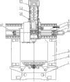
Accompanying drawing 1 is a kind of structural representation of the present invention;
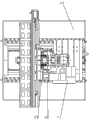
Accompanying drawing 3 is side structure schematic diagrames of Fig. 1;
Accompanying drawing 4 is perspective view of the present invention.
Parts, position and numbering among the figure: base 1, workbench 2, column 3, crossbeam 4, saddle 5, tool magazine carriage 6, tool magazine 7, beam guideway 8, motor cabinet 9, servomotor 10, ball screw 11, nut seat 12, ram 13, main motor 14, compensating cylinder 15, table slide 16, workbench motor 17, workbench screw mandrel 18.
The specific embodiment
Below by embodiment, and in conjunction with the accompanying drawings, technical scheme of the present invention is described in further detail.
Embodiment: a kind of tool magazine of this example and main shaft are contained in the numerical control gantry machining center on the saddle altogether, as Fig. 1, Fig. 2, Fig. 3, Fig. 4, a base 1 is arranged, base is provided with workbench 2, base is provided with table slide 16, and workbench is movably connected on the table slide, and base is provided with workbench motor 17, the workbench motor is connected with workbench screw mandrel 18, and workbench is by the workbench screw mandrel that is threaded.Base 1 is connected with two root posts 3, and the column top is fixed with crossbeam 4, and crossbeam is provided with two beam guideways 8 that be arranged in parallel, and saddle 5 is movably connected on the beam guideway, and the saddle top is connected with compensating cylinder 15.Crossbeam is provided with motor cabinet 9, is fixed with servomotor 10 on the motor cabinet, and servomotor is connected with ball screw 11, and saddle 5 is movably connected on the ball screw by screw thread, and the end of ball screw is connected with nut seat 12, and nut seat is fixed on the crossbeam.Saddle is provided with tool magazine carriage 6, is connected with tool magazine 7 on the tool magazine carriage.Also be connected with the ram 13 that can move up and down on the saddle, be fixed with main motor 14 on the ram.
During use, on workbench 2, fix workpiece to be processed, utilize workbench screw mandrel 18 to adjust the front and back position of workbench, utilize ball screw 11 to adjust the position, the left and right sides of saddles 5, after ram 13 moves downward, main motor 14 be positioned at workpiece directly over.The main tapping that install at main motor place can be processed workpiece.When needing tool changing, main tapping can move to tool magazine 7 next doors and carry out automatic tool changer, then workpiece is carried out next step processing.
The above only is specific embodiments of the invention, but architectural feature of the present invention is not limited thereto, and any those skilled in the art is in the field of the invention, and the variation of being done or modify all is encompassed among the claim of the present invention.
Claims (5)
1. tool magazine and main shaft are contained in the numerical control gantry machining center on the saddle altogether, comprise base (1), base is provided with workbench (2), it is characterized in that described base (1) is connected with two root posts (3), the column top is fixed with crossbeam (4), crossbeam is connected with saddle (5) by cross beam translation mechanism, and saddle is provided with tool magazine carriage (6) and main shaft device, is connected with the tool magazine (7) towards main shaft device on the tool magazine carriage.
2. a kind of tool magazine according to claim 1 and main shaft are contained in the numerical control gantry machining center on the saddle altogether, it is characterized in that described cross beam translation mechanism includes the beam guideway (8) that is located on the crossbeam (4), saddle (5) is movably connected on the beam guideway, crossbeam is provided with motor cabinet (9), be fixed with servomotor (10) on the motor cabinet, servomotor is connected with ball screw (11), saddle (5) is movably connected on the ball screw by screw thread, the end of ball screw is connected with nut seat (12), and nut seat is fixed on the crossbeam.
3. a kind of tool magazine according to claim 1 and 2 and main shaft are contained in the numerical control gantry machining center on the saddle altogether, it is characterized in that described main shaft device includes the ram that can slide up and down (13) that is movably connected on the saddle (5), is fixed with main motor (14) on the ram.
4. a kind of tool magazine according to claim 1 and 2 and main shaft are contained in the numerical control gantry machining center on the saddle altogether, it is characterized in that described saddle (5) top is connected with compensating cylinder (15).
5. a kind of tool magazine according to claim 1 and 2 and main shaft are contained in the numerical control gantry machining center on the saddle altogether, it is characterized in that described base (1) is provided with table slide (16), workbench is movably connected on the table slide, base is provided with workbench motor (17), the workbench motor is connected with workbench screw mandrel (18), and workbench (2) is by the workbench screw mandrel that is threaded.
Priority Applications (1)
| Application Number | Priority Date | Filing Date | Title |
|---|---|---|---|
| CN2011102203308A CN102294599A (en) | 2011-08-03 | 2011-08-03 | Numerically controlled gantry processing centre with tool storage and main shaft both arranged on slide saddle |
Applications Claiming Priority (1)
| Application Number | Priority Date | Filing Date | Title |
|---|---|---|---|
| CN2011102203308A CN102294599A (en) | 2011-08-03 | 2011-08-03 | Numerically controlled gantry processing centre with tool storage and main shaft both arranged on slide saddle |
Publications (1)
| Publication Number | Publication Date |
|---|---|
| CN102294599A true CN102294599A (en) | 2011-12-28 |
Family
ID=45355401
Family Applications (1)
| Application Number | Title | Priority Date | Filing Date |
|---|---|---|---|
| CN2011102203308A Pending CN102294599A (en) | 2011-08-03 | 2011-08-03 | Numerically controlled gantry processing centre with tool storage and main shaft both arranged on slide saddle |
Country Status (1)
| Country | Link |
|---|---|
| CN (1) | CN102294599A (en) |
Cited By (7)
| Publication number | Priority date | Publication date | Assignee | Title |
|---|---|---|---|---|
| CN103586699A (en) * | 2013-10-23 | 2014-02-19 | 杭州大天数控机床有限公司 | High-rigidity square ram gantry machining center |
| CN103817529A (en) * | 2014-02-21 | 2014-05-28 | 东莞市美迈士机械科技有限公司 | Turning-milling combination machine |
| CN103846709A (en) * | 2014-01-23 | 2014-06-11 | 滕州市大地机床股份有限公司 | Built-in tool magazine structure |
| CN106312652A (en) * | 2016-10-17 | 2017-01-11 | 广东钶锐锶数控技术有限公司 | Machining device and machining method implemented by adoption of machining device |
| CN110666561A (en) * | 2019-09-19 | 2020-01-10 | 贵州宝康智能装备有限公司 | Machining center with movable tool magazine |
| CN112222869A (en) * | 2020-09-18 | 2021-01-15 | 乔锋智能装备股份有限公司 | 5G product machining center |
| CN112676893A (en) * | 2020-12-18 | 2021-04-20 | 青岛捷美达数控机械有限公司 | Main spindle box of numerical control machining center |
Citations (7)
| Publication number | Priority date | Publication date | Assignee | Title |
|---|---|---|---|---|
| US4497410A (en) * | 1979-11-13 | 1985-02-05 | The Lodge & Shipley Company | Automatic tool changer for a lathe |
| CN1562556A (en) * | 2004-03-31 | 2005-01-12 | 沈阳工业学院 | Fast vertical/horizontal type boring and milling automatic processing center |
| CN101502933A (en) * | 2009-03-10 | 2009-08-12 | 吉林省鸿源机床制造有限责任公司 | Numerical control gantry heavy-duty machine for machining, milling, boring, planing and grinding |
| CN101623821A (en) * | 2009-03-28 | 2010-01-13 | 广州市敏嘉制造技术有限公司 | Six-axle five-linkage airscrew processing center |
| CN201524905U (en) * | 2009-02-09 | 2010-07-14 | 深圳市康铖机械设备有限公司 | Small portal double main shaft drilling and milling numerically-controlled machine tool |
| CN201856088U (en) * | 2010-09-17 | 2011-06-08 | 王元庆 | Moving beam type numerical control gantry combined machine tool |
| CN202180342U (en) * | 2011-08-03 | 2012-04-04 | 杭州大天数控机床有限公司 | Numerical control portal machining center with tool storage and spindle jointly mounted on sliding saddle |
-
2011
- 2011-08-03 CN CN2011102203308A patent/CN102294599A/en active Pending
Patent Citations (7)
| Publication number | Priority date | Publication date | Assignee | Title |
|---|---|---|---|---|
| US4497410A (en) * | 1979-11-13 | 1985-02-05 | The Lodge & Shipley Company | Automatic tool changer for a lathe |
| CN1562556A (en) * | 2004-03-31 | 2005-01-12 | 沈阳工业学院 | Fast vertical/horizontal type boring and milling automatic processing center |
| CN201524905U (en) * | 2009-02-09 | 2010-07-14 | 深圳市康铖机械设备有限公司 | Small portal double main shaft drilling and milling numerically-controlled machine tool |
| CN101502933A (en) * | 2009-03-10 | 2009-08-12 | 吉林省鸿源机床制造有限责任公司 | Numerical control gantry heavy-duty machine for machining, milling, boring, planing and grinding |
| CN101623821A (en) * | 2009-03-28 | 2010-01-13 | 广州市敏嘉制造技术有限公司 | Six-axle five-linkage airscrew processing center |
| CN201856088U (en) * | 2010-09-17 | 2011-06-08 | 王元庆 | Moving beam type numerical control gantry combined machine tool |
| CN202180342U (en) * | 2011-08-03 | 2012-04-04 | 杭州大天数控机床有限公司 | Numerical control portal machining center with tool storage and spindle jointly mounted on sliding saddle |
Cited By (8)
| Publication number | Priority date | Publication date | Assignee | Title |
|---|---|---|---|---|
| CN103586699A (en) * | 2013-10-23 | 2014-02-19 | 杭州大天数控机床有限公司 | High-rigidity square ram gantry machining center |
| CN103846709A (en) * | 2014-01-23 | 2014-06-11 | 滕州市大地机床股份有限公司 | Built-in tool magazine structure |
| CN103817529A (en) * | 2014-02-21 | 2014-05-28 | 东莞市美迈士机械科技有限公司 | Turning-milling combination machine |
| CN106312652A (en) * | 2016-10-17 | 2017-01-11 | 广东钶锐锶数控技术有限公司 | Machining device and machining method implemented by adoption of machining device |
| CN106312652B (en) * | 2016-10-17 | 2019-01-15 | 广东钶锐锶数控技术有限公司 | A kind of process equipment and the processing method using its realization |
| CN110666561A (en) * | 2019-09-19 | 2020-01-10 | 贵州宝康智能装备有限公司 | Machining center with movable tool magazine |
| CN112222869A (en) * | 2020-09-18 | 2021-01-15 | 乔锋智能装备股份有限公司 | 5G product machining center |
| CN112676893A (en) * | 2020-12-18 | 2021-04-20 | 青岛捷美达数控机械有限公司 | Main spindle box of numerical control machining center |
Similar Documents
| Publication | Publication Date | Title |
|---|---|---|
| CN103350343B (en) | The numerical control gantry vertical that a kind of tool magazine and main shaft are compounded in saddle crouches Compositions of metal-working machines | |
| CN102161159B (en) | Vertical-horizontal combined machining centre | |
| CN101961836B (en) | Numerically-controlled gantry type vertical and horizontal combined machine tool | |
| CN201856088U (en) | Moving beam type numerical control gantry combined machine tool | |
| CN201970090U (en) | Vertical-horizontal combined machining center | |
| CN201799851U (en) | Numerical-control vertical combined gantry machine tool | |
| CN201792194U (en) | Numerical control gantry vertical-horizontal combined machine tool | |
| CN202037447U (en) | Vertical machining center with fixed worktable | |
| CN101966650A (en) | Numerical control gantry vertical combined machine tool | |
| CN102294599A (en) | Numerically controlled gantry processing centre with tool storage and main shaft both arranged on slide saddle | |
| CN206825066U (en) | A kind of Five-axis NC Machining Center of novel horizontal main shaft | |
| CN101502933A (en) | Numerical control gantry heavy-duty machine for machining, milling, boring, planing and grinding | |
| CN206084384U (en) | Wheel hub's rim machine tool | |
| CN203343729U (en) | Numerically-controlled gantry vertical-and-horizontal compound machining center with tool magazines and main shafts compounded on saddles | |
| CN202180342U (en) | Numerical control portal machining center with tool storage and spindle jointly mounted on sliding saddle | |
| CN201792240U (en) | Horizontal high-speed spindle device | |
| CN202240446U (en) | Numerical control gate pentahedral machine tool | |
| CN211465467U (en) | Turning and milling combined equipment | |
| CN202155707U (en) | Numerical control machining center | |
| CN205651075U (en) | Longmen machining center | |
| CN103586698A (en) | Machining center for gantry with four linear rails and ram | |
| CN201881185U (en) | Vertical high-speed main shaft device | |
| CN112338291A (en) | Novel rack shaping special grinding machine | |
| CN202062247U (en) | Horizontal type processing center with fixed worktable | |
| CN201833181U (en) | Composite stand column device of numerical control machine |
Legal Events
| Date | Code | Title | Description |
|---|---|---|---|
| C06 | Publication | ||
| PB01 | Publication | ||
| C10 | Entry into substantive examination | ||
| SE01 | Entry into force of request for substantive examination | ||
| C12 | Rejection of a patent application after its publication | ||
| RJ01 | Rejection of invention patent application after publication |
Application publication date: 20111228 |