CN203343729U - Numerically-controlled gantry vertical-and-horizontal compound machining center with tool magazines and main shafts compounded on saddles - Google Patents
Numerically-controlled gantry vertical-and-horizontal compound machining center with tool magazines and main shafts compounded on saddles Download PDFInfo
- Publication number
- CN203343729U CN203343729U CN 201320327414 CN201320327414U CN203343729U CN 203343729 U CN203343729 U CN 203343729U CN 201320327414 CN201320327414 CN 201320327414 CN 201320327414 U CN201320327414 U CN 201320327414U CN 203343729 U CN203343729 U CN 203343729U
- Authority
- CN
- China
- Prior art keywords
- vertical
- horizontal
- saddle
- screw mandrel
- crossbeam
- Prior art date
- Legal status (The legal status is an assumption and is not a legal conclusion. Google has not performed a legal analysis and makes no representation as to the accuracy of the status listed.)
- Expired - Fee Related
Links
Images


Abstract
The utility model relates to a numerically-controlled gantry vertical-and-horizontal compound machining center with tool magazines and main shafts compounded on saddles. The numerically-controlled gantry vertical-and-horizontal compound machining center with the tool magazines and the main shafts compounded on the saddles solves the problems that due to the fact that a tool magazine is not arranged on a vertical main shaft or a horizontal main shaft of a machine tool, tools cannot be timely replaced, working efficiency is low, and the structure of the machine tool cannot meet the requirements for high efficiency, precision, energy saving and composition. The numerically-controlled gantry vertical-and-horizontal compound machining center with the tool magazines and the main shafts compounded on the saddles comprises a base, a workbench and a vertical column, wherein the vertical column is movably connected with a transverse beam through a vertical column guide rail, the transverse beam is movably connected with a transverse beam saddle through a transverse beam guide rail, the vertical column is movably connected with a vertical column saddle through the vertical column guide rail, the transverse beam saddle is movably connected with a vertical main shaft device through a vertical ram guide rail, the vertical column saddle is movably connected with a horizontal main shaft device, the tool magazines are fixed to the transverse beam saddle and the vertical column saddle through tool magazine brackets, the base, the vertical column, the transverse beam, the vertical main shaft device, the horizontal main shaft device are provided with lead screw driving devices respectively, and the tool magazines, the lead screw driving devices and the main shaft devices are all connected with an electrical numerical control device.
Description
Technical field
The utility model relates to a kind of Digit Control Machine Tool, especially relates to the vertical sleeping Compositions of metal-working machines of numerical control gantry that a kind of tool magazine and main shaft are compounded in saddle.
Background technology
Digital controlled planer machine, mainly consist of lathe bed, workbench, left and right pillar, crossbeam, saddle, main speed reduction box, console, electric control box and driving control device.Can complete mill, the multistage manufacturing processes such as brill, hinge, boring, be applicable to the Roughing and fine machining of the large and medium-sized part of every profession and trade.Chinese patent discloses a kind of numerical control gantry heavy-duty machine for machining, milling, boring, planing and grinding, and (publication number: CN 101502933A), it is comprised of lathe bed, carriage, composite pillar, crossbeam, back timber, rotary motive power head, chuck, tailstock, main drive gear, bistrique, milling and boring heads, planing frame, turning tool rest, electric control system etc.; Carriage is by the line slideway guiding on lathe bed, and carriage is completed the reciprocating motion of carriage by main drive motor, main drive gear, gear, tooth bar, moves back and forth velocity interval: O.02-60000mm/min; Two composite pillars are connected with securing member respectively with the lathe bed two sides; Back timber is connected with securing member with two composite pillar upper surfaces; Crossbeam is arranged on respectively on the guide rail of composite pillar both sides, utilizes two driven by servomotor of lifting one's head, and drives leading screw and rotates, thereby complete crossbeam, moves up and down; Milling and boring heads on crossbeam, turning tool rest are used respectively driven by servomotor, drive leading screw and rotate, and complete milling and boring heads, turning tool rest traverse feed; Bistrique on crossbeam, planing frame are used respectively driven by servomotor, drive leading screw and rotate, and complete bistrique, planing frame traverse feed; Bistrique on two composite pillars, planing frame are arranged on respectively on the guide rail of composite pillar, use respectively driven by servomotor, drive leading screw and rotate, and complete bistrique, the motion of planing frame bottom and top feed.But tool magazine all is not set on the vertical spindle of this lathe, horizontal main axis, thereby tool changing in time, operating efficiency is lower, and bistrique, planing frame are set on column, can not carry out the left and right feed motion, the milling and boring heads arranged on crossbeam, tool holder, bistrique, planing frame can not carry out upper and lower precision feeding motion, and machine tool structure can not be suitable for the high-efficiency and precision process requirements.
The utility model content
The utility model is to provide the vertical sleeping Compositions of metal-working machines of numerical control gantry that a kind of tool magazine and main shaft are compounded in saddle, it is mainly, on the vertical spindle that solves the existing lathe of prior art, horizontal main axis, tool magazine all is not set, thereby tool changing in time, operating efficiency is lower, and bistrique, planing frame are set on column, can not carry out the left and right feed motion, the milling and boring heads arranged on crossbeam, tool holder, bistrique, planing frame can not carry out upper and lower precision feeding motion, and machine tool structure can not be suitable for the technical problem of high-efficiency and precision process requirements etc.
Above-mentioned technical problem of the present utility model is mainly solved by following technical proposals:
A kind of tool magazine of the present utility model and main shaft are compounded in the vertical sleeping Compositions of metal-working machines of numerical control gantry of saddle, comprise base, workbench, column, described column is connected with crossbeam by column guide rail, crossbeam is connected with the crossbeam saddle more than 1 by beam guideway, at least one root post is connected with the column saddle by column guide rail, the crossbeam saddle is connected with the vertical spindle device by vertical ram gib, and the column saddle is connected with the horizontal main axis device by horizontal ram gib; Be fixed with tool magazine by the tool magazine carriage on crossbeam saddle, column saddle, base, column, crossbeam, vertical spindle device, horizontal main axis device are provided with screw rod driving device, and tool magazine, screw rod driving device, main shaft device all connect electric numerical control device.
Tool magazine directly is fixed on crossbeam saddle, column saddle, can be so that vertical spindle device, horizontal main axis device automatic tool changer has as required improved working (machining) efficiency.
Crossbeam saddle on crossbeam can be more than 1, and the vertical spindle device can be also, more than 1, to process convenient like this.
Vertical spindle device and horizontal main axis device can move up and down on crossbeam and column; Workpiece is installed on workbench and is moved forward and backward, and plural main shaft device carries out efficient, compound, energy-conservation, the Precision Machining of two above operations to workpiece.Crossbeam top can be provided with back timber, or crossbeam and back timber are made one.
As preferably, described tool magazine is disc type tool magazine or bamboo hat type tool holder.
As preferably, described crossbeam is movably connected on two root posts by column guide rail, be provided with the stand column and beam screw mandrel in column, the stand column and beam screw mandrel is connected with the stand column and beam drive motors, the stand column and beam drive motors is fixed on an end of column by stand column and beam drive motors seat, the stand column and beam screw mandrel shaft block is fixed on the column another end, is provided with bearing in bearing block, and the stand column and beam screw mandrel is flexibly connected crossbeam by stand column and beam feed screw nut seat.Like this, crossbeam just can rely on the stand column and beam screw mandrel to move up and down on column, makes the vertical spindle device adapt to the high and low position of workpiece.
As preferably, described column saddle is movably connected on column by column guide rail, be provided with column saddle screw mandrel in column, column saddle screw mandrel is connected with column saddle drive motors, column saddle drive motors is fixed on an end of column by column saddle motor cabinet, column saddle screw mandrel shaft block is fixed on the column another end, is provided with bearing in bearing block, and column saddle screw mandrel is flexibly connected the column saddle by column saddle nut seat.Like this, the column saddle just can rely on the stand column and beam screw mandrel to move up and down on column, makes the horizontal main axis device adapt to the high and low position of workpiece.
As preferably, described crossbeam is flexibly connected the crossbeam saddle by beam guideway, crossbeam is provided with the crossbeam screw mandrel, the crossbeam saddle has the nut seat of connecting cross beam screw mandrel, the crossbeam screw mandrel is connected with the crossbeam drive motors at an end of crossbeam, the crossbeam drive motors is fixed on crossbeam by the crossbeam motor cabinet, and the crossbeam screw mandrel is connected with the crossbeam bearing block at the other end of crossbeam, in the crossbeam bearing block, is provided with bearing; Perhaps the crossbeam saddle is fixedly connected on crossbeam by securing member.By crossbeam saddle drive motors, drive crossbeam saddle screw mandrel to rotate, thereby drive the transverse shifting of vertical spindle device, make the vertical spindle device adapt to the position, left and right of workpiece.Be provided with bearing in crossbeam saddle bearing block, can facilitate vertical screw mandrel rotation.The vertical spindle device all connects a rhizoid bar, and every rhizoid bar connects a drive unit, and drive unit is located at an end of crossbeam, drives the vertical spindle device; Can realize high efficiency composition processing.
As preferably, described crossbeam saddle is provided with vertical compensating cylinder, vertical compensating cylinder upper end is connected with vertical compensating cylinder support, and vertical compensating cylinder support is fixed on the vertical ram of vertical spindle device, and the crossbeam saddle is flexibly connected vertical ram by vertical ram gib.Smoothness when compensating cylinder can improve the vertical high-speed main shaft device vertical feed, be conducive to lathe and realize Precision Machining.
As preferably, described horizontal main axis device is Horizontal high-speed spindle device, comprise the column saddle, it is flexibly connected horizontal ram by horizontal ram gib, be provided with horizontal screw mandrel in the column saddle, the column screw mandrel is connected with horizontal drive motors, the column drive motors is fixed on horizontal saddle by horizontal drive motors seat, be provided with the Horizontal axle bearing in horizontal saddle, be provided with horizontal bearing between Horizontal axle bearing and horizontal screw mandrel, horizontal screw mandrel is connected with horizontal ram, be fixed with horizontal knife striking cylinder by horizontal knife striking cylinder support on horizontal ram, horizontal knife striking cylinder one side is provided with the horizontal high-speed main shaft, the horizontal high-speed main shaft is connected with the horizontal synchronous belt wheel by Timing Belt, the horizontal synchronous belt wheel is connected on horizontal main motor, horizontal main motor is fixed on horizontal ram by horizontal main motor cabinet.Horizontal drive motors can drive horizontal screw mandrel and be rotated, thereby drive whole ram, carries out side-to-side movement; Horizontal main motor drives the horizontal high-speed main shaft to realize high speed and high precision processing.
As preferably, described horizontal main axis device is Horizontal type low speed spindle device, comprise the column saddle, it is flexibly connected horizontal ram by horizontal ram gib, be provided with horizontal screw mandrel in the column saddle, horizontal screw mandrel is connected with horizontal drive motors, horizontal drive motors is fixed on horizontal saddle by horizontal drive motors seat, be provided with the Horizontal axle bearing in horizontal saddle, be provided with horizontal bearing between Horizontal axle bearing and horizontal screw mandrel, horizontal screw mandrel is connected with horizontal ram, be fixed with horizontal knife striking cylinder by horizontal knife striking cylinder support on horizontal ram, horizontal knife striking cylinder one side is provided with the Horizontal type low speed main shaft, the Horizontal type low speed main shaft is by being connected with the horizontal synchronous belt wheel, the horizontal synchronous belt wheel is connected on horizontal main motor by horizontal gear reduction box, horizontal main motor is fixed on horizontal ram by horizontal main motor cabinet.Horizontal main motor drives the Horizontal type low speed main shaft to realize that deceleration increases knuckling and can process.
As preferably, described horizontal main axis device is Horizontal grinding main shaft device, comprise the column saddle, it is flexibly connected horizontal ram by horizontal ram gib, be provided with horizontal screw mandrel in the column saddle, horizontal screw mandrel is connected with horizontal drive motors, horizontal drive motors is fixed on horizontal saddle and is provided with the Horizontal axle bearing in horizontal saddle by horizontal drive motors seat, be provided with horizontal bearing between Horizontal axle bearing and horizontal screw mandrel, horizontal screw mandrel is connected with horizontal ram, be connected with horizontal mount pad on horizontal ram, horizontal mount pad is provided with can be to the horizontal grinding head body of either direction rotation in same vertical plane, horizontal grinding head body two ends are respectively equipped with horizontal main motor and emery wheel.Horizontal drive motors can drive horizontal screw mandrel and be rotated, thereby drive whole horizontal mount pad, carries out side-to-side movement.After horizontal main motor drives emery wheel to rotate, can carry out cross grinding or the processing of peripheral accurate grinding to workpiece.
As preferably, described horizontal main axis device is that horizontal boring and milling bores main shaft device, comprise the column saddle, it is flexibly connected horizontal workbench by horizontal ram gib, be provided with horizontal screw mandrel in the column saddle, horizontal screw mandrel is connected with horizontal drive motors, horizontal drive motors is fixed on horizontal saddle by horizontal drive motors seat, be provided with the Horizontal axle bearing in horizontal saddle, be provided with horizontal bearing between Horizontal axle bearing and horizontal screw mandrel, horizontal screw mandrel is connected with horizontal workbench, and horizontal workbench is equipped with boring head, or drilling head or milling head.Horizontal drive motors can drive horizontal screw mandrel and be rotated, thereby drives horizontal workbench and the boring and milling drilling head carries out side-to-side movement, can carry out conventional boring and milling to workpiece and bore processing.
As preferably, described horizontal main axis device is the horizontal high-speed electric main shaft device, comprise the column saddle, it is flexibly connected horizontal ram by horizontal ram gib, be provided with horizontal screw mandrel in the column saddle, horizontal screw mandrel is connected with horizontal drive motors, horizontal drive motors is fixed on horizontal saddle and is provided with the Horizontal axle bearing in horizontal saddle by horizontal drive motors seat, be provided with horizontal bearing between Horizontal axle bearing and horizontal screw mandrel, horizontal screw mandrel is connected with horizontal ram, is connected with the Horizontal electric main shaft on horizontal ram.Horizontal drive motors can drive horizontal screw mandrel and be rotated, thereby drive whole horizontal ram, carries out side-to-side movement.After horizontal main motor drives horizontal high-speed electricity main shaft to rotate, can carry out the high-speed and high-efficiency processing more than 15000rmp to workpiece.
As preferably, described vertical spindle device is vertical high-speed main shaft device, comprise the crossbeam saddle, it is flexibly connected vertical ram by vertical ram gib, be provided with vertical screw mandrel in the crossbeam saddle, vertical screw mandrel is connected with vertical drive motors, vertical drive motors is fixed on the crossbeam saddle by vertical drive motors seat, be provided with the vertical shaft bearing in the crossbeam saddle, be provided with vertical bearing between vertical shaft bearing and vertical screw mandrel, vertical screw mandrel is connected with vertical ram, be fixed with vertical knife striking cylinder by vertical knife striking cylinder support on vertical ram, vertical knife striking cylinder below is provided with the vertical and high-speed main shaft, the vertical and high-speed main shaft is connected with vertical synchronous pulley by Timing Belt, vertical synchronous pulley is connected on vertical main motor, vertical main motor is fixed on vertical ram by vertical main motor cabinet.Vertical drive motors can drive vertical screw mandrel and be rotated, thereby drive whole ram, is moved up and down; Vertical main motor drives the vertical and high-speed main shaft to carry out high speed and precision processing.
As preferably, described vertical spindle device is vertical low speed spindle device, comprise the crossbeam saddle, it is flexibly connected vertical ram by vertical ram gib, be provided with vertical screw mandrel in the crossbeam saddle, vertical screw mandrel is connected with vertical drive motors, vertical drive motors is fixed on the crossbeam saddle by vertical drive motors seat, be provided with the vertical shaft bearing in the crossbeam saddle, be provided with vertical bearing between vertical shaft bearing and vertical screw mandrel, vertical screw mandrel is connected with vertical ram, be fixed with vertical knife striking cylinder by vertical knife striking cylinder support on vertical ram, vertical knife striking cylinder below is provided with the vertical low speed main shaft, the vertical low speed main shaft is connected with vertical synchronous pulley by Timing Belt, vertical synchronous pulley is connected on vertical main motor by the vertical gear reduction box, vertical main motor is fixed on vertical ram by vertical main motor cabinet.Vertical drive motors can drive vertical screw mandrel and be rotated, thereby drive whole ram, is moved up and down.Vertical main motor drives the vertical low speed main shaft to slow down to increase knuckling and can process.
As preferably, described vertical spindle device is vertical grinding main shaft device, comprise the crossbeam saddle, it is flexibly connected vertical ram by vertical ram gib, be provided with vertical screw mandrel in the crossbeam saddle, vertical screw mandrel is connected with vertical drive motors, vertical drive motors is fixed on the crossbeam saddle by vertical drive motors seat, be provided with the vertical shaft bearing in the crossbeam saddle, be provided with vertical bearing between vertical shaft bearing and vertical screw mandrel, vertical screw mandrel is connected with vertical ram, vertical ram is provided with vertical mount pad, vertical mount pad is provided with can be to the vertical grinding head body of either direction rotation in same vertical plane, vertical grinding head body two ends are respectively equipped with vertical main motor and emery wheel.Vertical drive motors can drive vertical screw mandrel and be rotated, thereby drive whole vertical mount pad, is moved up and down.After vertical main motor drives emery wheel to rotate, can carry out cross grinding or the processing of peripheral accurate grinding to workpiece.
As preferably, described vertical spindle device is the vertical and high-speed electric main shaft device, comprise the crossbeam saddle, it is flexibly connected vertical ram by vertical ram gib, be provided with vertical screw mandrel in the crossbeam saddle, vertical screw mandrel is connected with vertical drive motors, vertical drive motors is fixed on the crossbeam saddle by vertical drive motors seat, be provided with the vertical shaft bearing in the crossbeam saddle, be provided with vertical bearing between vertical shaft bearing and vertical screw mandrel, vertical screw mandrel is connected with vertical ram, on vertical ram, is connected with vertical electric main shaft.Vertical drive motors can drive vertical screw mandrel and be rotated, thereby drive whole vertical electric main shaft, is moved up and down.After vertical main motor drives vertical electric main shaft to rotate, can carry out the high speed and precision processing more than 15000rmp to workpiece.
Therefore the utility model is installed respectively tool magazine on crossbeam saddle, column saddle, can be so that vertical spindle device, horizontal main axis device automatic tool changer has as required improved working (machining) efficiency; And novel accurate vertical or horizontal main axis device more than two is installed on lathe, and the workpiece clamped one time just can be realized the high efficiency composition processing of two above operations, can reduce the repeated clamping error and improve Workpiece Machining Accuracy; Configuration high-speed main shaft device or high-speed electric main shaft device are realized high-speed and high-efficiency processing, and the configuration deceleration increases the low speed spindle device of turning round and realizes heavy load cutting and energy-conservation processing, and the configuration grinding main shaft device is realized cross grinding or peripheral grinding Precision Machining.
The accompanying drawing explanation
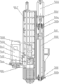
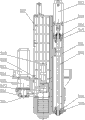
Accompanying drawing 1 is a kind of structural representation of the present utility model;
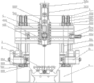
Accompanying drawing 2 is a kind of plan structure schematic diagrames of Fig. 1;
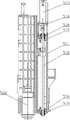
Accompanying drawing 3 is a kind of side structure schematic diagrames of Fig. 1;
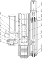
Accompanying drawing 4 is a kind of structural representations of the utility model Horizontal high-speed spindle device;
Accompanying drawing 5 is a kind of structural representations of the utility model Horizontal type low speed spindle device;
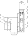
Accompanying drawing 6 is a kind of structural representations of the utility model Horizontal grinding main shaft device;
Accompanying drawing 7 is a kind of structural representations of the horizontal boring and milling main shaft device of the utility model;
Accompanying drawing 8 is a kind of structural representations of the utility model horizontal high-speed electric main shaft device;
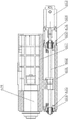
Accompanying drawing 9 is a kind of structural representations of the utility model vertical high-speed main shaft device;
Accompanying drawing 10 is a kind of side structure schematic diagrames of Fig. 9;
Accompanying drawing 11 is a kind of structural representations of the utility model vertical low speed spindle device;
Accompanying drawing 13 is a kind of structural representations of the utility model vertical grinding main shaft device;
Accompanying drawing 14 is a kind of side structure schematic diagrames of Figure 13;
Accompanying drawing 15 is a kind of structural representations of the utility model vertical and high-speed electric main shaft device;
Accompanying drawing 16 is a kind of side structure schematic diagrames of Figure 15;
Accompanying drawing 17 is a kind of structural representations that the utility model crossbeam saddle is installed disc type tool magazine;
Accompanying drawing 18 is side structure schematic diagrames of Figure 17;
Accompanying drawing 19 is a kind of structural representations that the utility model column saddle is installed disc type tool magazine;
Accompanying drawing 20 is plan structure schematic diagrames of Figure 19;
Accompanying drawing 21 is a kind of structural representations that the utility model crossbeam saddle is installed bamboo hat type tool holder;
Accompanying drawing 22 is side structure schematic diagrames of Figure 21;
Accompanying drawing 23 is a kind of structural representations that the utility model column saddle is installed bamboo hat type tool holder;
Accompanying drawing 24 is plan structure schematic diagrames of Figure 23;
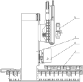
Accompanying drawing 25 is a kind of structural representations of the utility model embodiment 6;
Accompanying drawing 26 is a kind of plan structure schematic diagrames of Figure 25;
Accompanying drawing 27 is a kind of side structure schematic diagrames of Figure 25.
Parts in figure, position and numbering: base 1, workbench 2, column 3, stand column and beam screw mandrel 301, stand column and beam drive motors 302, stand column and beam drive motors seat 303, stand column and beam screw mandrel shaft block 304, stand column and beam feed screw nut's seat 305, column saddle screw mandrel 306, column saddle drive motors 307, column saddle motor cabinet 308, column saddle screw mandrel shaft block 309, column saddle nut seat 310, crossbeam 4, beam guideway 401, crossbeam saddle screw mandrel 402, crossbeam saddle drive motors 403, crossbeam saddle motor cabinet 404, crossbeam saddle bearing block 405, vertical spindle device 5, crossbeam saddle 501, vertical screw mandrel 502, vertical drive motors 503, vertical drive motors seat 504, vertical shaft bearing 505, vertical bearing 506, vertical ram 507, vertical knife striking cylinder support 508, vertical knife striking cylinder 509, vertical and high-speed main shaft 510, Timing Belt 511, vertical synchronous pulley 512, vertical main motor 513, vertical main motor cabinet 514, vertical gear reduction box 515, vertical mount pad 516, vertical grinding head body 517, emery wheel 518, vertical compensating cylinder 519, vertical compensating cylinder support 520, vertical pressing plate 521, vertical electric main shaft 522, vertical low speed main shaft 523, horizontal main axis device 6, column saddle 601, horizontal screw mandrel 602, horizontal drive motors 603, horizontal drive motors seat 604, Horizontal axle bearing 605, horizontal bearing 606, horizontal ram 607, horizontal knife striking cylinder support 608, horizontal knife striking cylinder 609, horizontal high-speed main shaft 610, Timing Belt 611, horizontal synchronous belt wheel 612, horizontal main motor 613, horizontal main motor cabinet 614, horizontal gear reduction box 615, horizontal mount pad 616, horizontal grinding head body 617, emery wheel 618, horizontal boring milling head 619, Horizontal electric main shaft 620, Horizontal type low speed main shaft 621, horizontal workbench 622, workbench screw mandrel 7, servomotor 8, servomotor seat 9, tool magazine carriage 10, disc type tool magazine 11, bamboo hat type tool holder 12.
The specific embodiment
Below by embodiment, and by reference to the accompanying drawings, the technical solution of the utility model is described in further detail.
Embodiment 1: the vertical sleeping Compositions of metal-working machines of the numerical control gantry that a kind of tool magazine of this example and main shaft are compounded in saddle, Fig. 3 as shown in Figure 1, Figure 2,, a base 1 is arranged, be connected with workbench 2 by guide rail on base, workbench is connected with workbench screw mandrel 7, the workbench screw mandrel is connected on servomotor 8, and servomotor is fixed on base by servomotor seat 9.Also be provided with two root posts 3 on base, column is fixedly connected with crossbeam 4, crossbeam top is fixed with back timber, crossbeam is provided with beam guideway 401, be connected with the vertical spindle device 5 more than 1 or 1 on beam guideway, be connected with the transversely movable horizontal main axis device 6 more than 1 or 1 by column saddle screw mandrel 306 on column, vertical spindle device, horizontal main axis device all connect electric numerical control device.The vertical spindle device is provided with crossbeam saddle 501, crossbeam is provided with the crossbeam saddle screw mandrel 402 be connected with saddle, crossbeam saddle screw mandrel is connected with crossbeam saddle drive motors 403 at an end of crossbeam, crossbeam saddle drive motors is fixed on crossbeam by crossbeam saddle motor cabinet 404, crossbeam saddle screw mandrel is connected with crossbeam saddle bearing block 405 at the other end of crossbeam, in crossbeam saddle bearing block, is provided with bearing.
As Figure 17,18, be fixed with disc type tool magazine 11 by tool magazine carriage 10 on crossbeam saddle 501, as Figure 19,20, on column saddle 601, by tool magazine carriage 10, be fixed with disc type tool magazine 11.
As Fig. 4, the horizontal main axis device is Horizontal high-speed spindle device, it includes column saddle 601, be provided with horizontal screw mandrel 602 in the column saddle, horizontal screw mandrel is connected with horizontal drive motors 603, horizontal drive motors is fixed on the column saddle by horizontal drive motors seat 604, be provided with Horizontal axle bearing 605 in the column saddle, be provided with horizontal bearing 606 between Horizontal axle bearing and horizontal screw mandrel, horizontal screw mandrel is connected with horizontal ram 607, be fixed with horizontal knife striking cylinder 609 by horizontal knife striking cylinder support 608 on horizontal ram, horizontal knife striking cylinder one side is provided with horizontal high-speed main shaft 610, the horizontal high-speed main shaft is connected with horizontal synchronous belt wheel 612 by Timing Belt 611, the horizontal synchronous belt wheel is connected on horizontal main motor 613, horizontal main motor is fixed on horizontal ram by horizontal main motor cabinet 614.
As Fig. 9, Figure 10, the vertical spindle device is vertical high-speed main shaft device, and it includes crossbeam saddle 501, and the crossbeam saddle is provided with vertical compensating cylinder 519, vertical compensating cylinder upper end is connected on vertical compensating cylinder support 520, also is connected with vertical pressing plate 521 on the crossbeam saddle.Be provided with vertical screw mandrel 502 in the crossbeam saddle, vertical screw mandrel is connected with vertical drive motors 503, vertical drive motors is fixed on the crossbeam saddle by vertical drive motors seat 504, be provided with vertical shaft bearing 505 in the crossbeam saddle, be provided with vertical bearing 506 between vertical shaft bearing and vertical screw mandrel, vertical screw mandrel is connected with vertical ram 507, be fixed with vertical knife striking cylinder 509 by vertical knife striking cylinder support 508 on vertical ram, vertical knife striking cylinder below is provided with vertical and high-speed main shaft 510, the vertical and high-speed main shaft is connected with vertical synchronous pulley 512 by Timing Belt 511, vertical synchronous pulley is connected on vertical main motor 513, vertical main motor is fixed on vertical ram by vertical main motor cabinet 514.
During use, by servomotor 7, drive 6 rotations of workbench screw mandrel, thereby adjust the position of workbench 2, make the workpiece working position aim at vertical spindle device 5 and horizontal stand column device.Drive 402 rotations of crossbeam saddle screw mandrel by crossbeam saddle drive motors 403, thereby adjust the lateral attitude of vertical spindle device.Adjusted the upper-lower position of vertical spindle head by vertical screw mandrel 502, after vertical main motor 513 starts, by the transmission of vertical synchronous pulley 512, Timing Belt 511, vertical and high-speed main shaft 510 is installed cutter, can be processed workpiece again.
Drive horizontal screw mandrel 602 rotations by horizontal drive motors 603, thereby adjust the position of horizontal main axis head 610, after horizontal main motor 613 starts, by the transmission of horizontal synchronous belt wheel 612, Timing Belt 611, horizontal high-speed main shaft 610 is installed cutter, can be processed workpiece.
Embodiment 2: the vertical sleeping Compositions of metal-working machines of the numerical control gantry that a kind of tool magazine of this example and main shaft are compounded in saddle, Fig. 3 as shown in Figure 1, Figure 2,, a base 1 is arranged, be connected with workbench 2 by guide rail on base, workbench is connected with workbench screw mandrel 7, the workbench screw mandrel is connected on servomotor 8, and servomotor is fixed on base by servomotor seat 9.Also be provided with two root posts 3 on base, column is fixedly connected with crossbeam 4, crossbeam top is fixed with back timber, crossbeam is provided with beam guideway 401, be connected with the vertical spindle device 5 more than 1 or 1 on beam guideway, be connected with the transversely movable horizontal main axis device 6 more than 1 or 1 by column saddle screw mandrel 306 on column, vertical spindle device, horizontal main axis device all connect electric numerical control device.The vertical spindle device is provided with crossbeam saddle 501, crossbeam is provided with the crossbeam saddle screw mandrel 402 be connected with saddle, crossbeam saddle screw mandrel is connected with crossbeam saddle drive motors 403 at an end of crossbeam, crossbeam saddle drive motors is fixed on crossbeam by crossbeam saddle motor cabinet 404, crossbeam saddle screw mandrel is connected with crossbeam saddle bearing block 405 at the other end of crossbeam, in crossbeam saddle bearing block, is provided with bearing.
As Figure 17,18, be fixed with disc type tool magazine 11 by tool magazine carriage 10 on crossbeam saddle 501, as Figure 19,20, on column saddle 601, by tool magazine carriage 10, be fixed with disc type tool magazine 11.
As Fig. 5, the horizontal main axis device is Horizontal type low speed spindle device, it includes column saddle 601, be provided with horizontal screw mandrel 602 in the column saddle, horizontal screw mandrel is connected with horizontal drive motors 603, horizontal drive motors is fixed on the column saddle by horizontal drive motors seat 604, be provided with Horizontal axle bearing 605 in the column saddle, be provided with horizontal bearing 606 between Horizontal axle bearing and horizontal screw mandrel, horizontal screw mandrel is connected with horizontal ram 607, be fixed with horizontal knife striking cylinder 609 by horizontal knife striking cylinder support 608 on horizontal ram, horizontal knife striking cylinder one side is provided with Horizontal type low speed main shaft 621, the Horizontal type low speed main shaft is connected with horizontal synchronous belt wheel 612 by Timing Belt 611, the horizontal synchronous belt wheel is connected on horizontal main motor 613 by horizontal gear reduction box 615, horizontal main motor is fixed on horizontal ram by horizontal main motor cabinet 614.
As Figure 11, Figure 12, the vertical spindle device is vertical low speed spindle device, and it includes crossbeam saddle 501, and the crossbeam saddle is provided with vertical compensating cylinder 519, vertical compensating cylinder upper end is connected on vertical compensating cylinder support 520, also is connected with vertical pressing plate 521 on the crossbeam saddle.Be provided with vertical screw mandrel 502 in the crossbeam saddle, vertical screw mandrel is connected with vertical drive motors 503, vertical drive motors is fixed on the crossbeam saddle by vertical drive motors seat 504, be provided with vertical shaft bearing 505 in the crossbeam saddle, be provided with vertical bearing 506 between vertical shaft bearing and vertical screw mandrel, vertical screw mandrel is connected with vertical ram 507, be fixed with vertical knife striking cylinder 509 by vertical knife striking cylinder support 508 on vertical ram, vertical knife striking cylinder below is provided with vertical spindle 510, vertical spindle is connected with vertical synchronous pulley 512 by Timing Belt 511, vertical synchronous pulley is connected on vertical main motor 513 by vertical gear reduction box 515, vertical main motor is fixed on vertical ram by vertical main motor cabinet 514.
During use, by servomotor 7, drive 6 rotations of workbench screw mandrel, thereby adjust the position of workbench 2, make the workpiece working position aim at vertical spindle device 5 and horizontal main axis device.Drive 402 rotations of crossbeam saddle screw mandrel by crossbeam saddle drive motors 403, thereby adjust the lateral attitude of vertical spindle device.Adjusted again the position of vertical knife striking cylinder 509 by vertical screw mandrel 502, after vertical main motor 513 starts, retarded motion through vertical gear reduction box 515, again by the transmission of vertical synchronous pulley 512, Timing Belt 511, vertical low speed main shaft 523 starts to slowly run, and the cutter connected thereon can be processed workpiece.
Drive horizontal screw mandrel 602 rotations by horizontal drive motors 603, thereby adjust the position of horizontal main axis 610, after horizontal main motor 613 starts, retarded motion through horizontal gear reduction box 615, low speed rotation by horizontal synchronous belt wheel 612, Timing Belt 611, Horizontal type low speed main shaft 621 starts to rotate, and installs cutter and can be processed workpiece.
Embodiment 3: the vertical sleeping Compositions of metal-working machines of the numerical control gantry that a kind of tool magazine of this example and main shaft are compounded in saddle, Fig. 3 as shown in Figure 1, Figure 2,, a base 1 is arranged, be connected with workbench 2 by guide rail on base, workbench is connected with workbench screw mandrel 7, the workbench screw mandrel is connected on servomotor 8, and servomotor is fixed on base by servomotor seat 9.Also be provided with two root posts 3 on base, column is fixedly connected with crossbeam 4, crossbeam top is fixed with back timber, crossbeam is provided with beam guideway 401, be connected with 1 vertical spindle device 5 on beam guideway, be connected with 6, two horizontal main axis devices of 2 transversely movable horizontal main axis devices by column saddle screw mandrel 306 on column and be oppositely arranged, vertical spindle device, horizontal main axis device all connect electric numerical control device.The vertical spindle device is provided with crossbeam saddle 501, crossbeam is provided with the crossbeam saddle screw mandrel 402 be connected with saddle, crossbeam saddle screw mandrel is connected with crossbeam saddle drive motors 403 at an end of crossbeam, crossbeam saddle drive motors is fixed on crossbeam by crossbeam saddle motor cabinet 404, crossbeam saddle screw mandrel is connected with crossbeam saddle bearing block 405 at the other end of crossbeam, in crossbeam saddle bearing block, is provided with bearing.
As Figure 17,18, be fixed with disc type tool magazine 11 by tool magazine carriage 10 on crossbeam saddle 501, as Figure 19,20, on column saddle 601, by tool magazine carriage 10, be fixed with disc type tool magazine 11.
As Fig. 6, the horizontal main axis device is Horizontal grinding main shaft device, it includes column saddle 601, be provided with horizontal screw mandrel 602 in the column saddle, horizontal screw mandrel is connected with horizontal drive motors 603, horizontal drive motors is fixed in column saddle upper pillar stand saddle and is provided with Horizontal axle bearing 605 by horizontal drive motors seat 604, be provided with horizontal bearing 606 between Horizontal axle bearing and horizontal screw mandrel, horizontal screw mandrel is connected with horizontal ram 607, be connected with horizontal mount pad 616 on horizontal ram, horizontal mount pad is provided with can be to the horizontal grinding head body 617 of either direction rotation in same vertical plane, horizontal grinding head body two ends are respectively equipped with horizontal main motor 613 and emery wheel 618.
As Figure 13, Figure 14, the vertical spindle device is vertical grinding main shaft device, it includes crossbeam saddle 501, the crossbeam saddle is provided with vertical compensating cylinder 519, vertical compensating cylinder upper end is connected on vertical compensating cylinder support 520, be provided with vertical screw mandrel 502 in the crossbeam saddle, vertical screw mandrel is connected with vertical drive motors 503, vertical drive motors is fixed on the crossbeam saddle by vertical drive motors seat 504, be provided with vertical shaft bearing 505 in the crossbeam saddle, be provided with vertical bearing 506 between vertical shaft bearing and vertical screw mandrel, vertical screw mandrel is connected with vertical ram 507, vertical ram is provided with vertical mount pad 516, vertical mount pad is provided with can be to the vertical grinding head body 517 of either direction rotation in same vertical plane, vertical grinding head body two ends are respectively equipped with vertical main motor 513 and emery wheel 518.
During use, by servomotor 7, drive 6 rotations of workbench screw mandrel, thereby adjust the position of workbench 2, make the workpiece working position aim at vertical spindle device 5 and horizontal main axis device.Drive 402 rotations of crossbeam saddle screw mandrel by crossbeam saddle drive motors 403, thereby adjust the lateral attitude of vertical spindle device.Adjusted the position of vertical grinding head body 517 by vertical screw mandrel 502, after vertical main motor 513 starts, the emery wheel 518 of vertical grinding head body 517 1 ends can carry out cross grinding or peripheral grinding to workpiece again.
Drive horizontal screw mandrel 602 rotations by horizontal drive motors 603, thereby adjust the position of horizontal grinding head body 617, after horizontal main motor 613 starts, the emery wheel 618 of horizontal grinding head body 617 1 ends can carry out cross grinding or peripheral grinding to workpiece.
Embodiment 4: the vertical sleeping Compositions of metal-working machines of the numerical control gantry that a kind of tool magazine of this example and main shaft are compounded in saddle, Fig. 3 as shown in Figure 1, Figure 2,, a base 1 is arranged, be connected with workbench 2 by guide rail on base, workbench is connected with workbench screw mandrel 7, the workbench screw mandrel is connected on servomotor 8, and servomotor is fixed on base by servomotor seat 9.Also be provided with two root posts 3 on base, column is fixedly connected with crossbeam 4, crossbeam top is fixed with back timber, crossbeam is provided with beam guideway 401, be connected with 1 vertical spindle device 5 on beam guideway, be connected with 6, two horizontal main axis devices of 2 transversely movable horizontal main axis devices by column saddle screw mandrel 306 on column and be oppositely arranged, vertical spindle device, horizontal main axis device all connect electric numerical control device.The vertical spindle device is provided with crossbeam saddle 501, crossbeam is provided with the crossbeam saddle screw mandrel 402 be connected with saddle, crossbeam saddle screw mandrel is connected with crossbeam saddle drive motors 403 at an end of crossbeam, crossbeam saddle drive motors is fixed on crossbeam by crossbeam saddle motor cabinet 404, crossbeam saddle screw mandrel is connected with crossbeam saddle bearing block 405 at the other end of crossbeam, in crossbeam saddle bearing block, is provided with bearing.
As Figure 21,22, be fixed with bamboo hat type tool holder 12 by tool magazine carriage 10 on crossbeam saddle 501, as Figure 23,24, on column saddle 601, by tool magazine carriage 10, be fixed with bamboo hat type tool holder 12.
As Fig. 7, the horizontal main axis device is horizontal boring and milling main shaft device, it includes column saddle 601, be provided with horizontal screw mandrel 602 in the column saddle, horizontal screw mandrel is connected with horizontal drive motors 603, horizontal drive motors is fixed in column saddle upper pillar stand saddle and is provided with Horizontal axle bearing 605 by horizontal drive motors seat 604, be provided with horizontal bearing 606 between Horizontal axle bearing and horizontal screw mandrel, horizontal screw mandrel is connected with horizontal workbench 622, be connected with horizontal mount pad 616 on horizontal ram, horizontal mount pad is provided with horizontal boring milling head 619, the horizontal boring milling head connects horizontal main motor 613.
As Fig. 9, Figure 10, the vertical spindle device is vertical high-speed main shaft device, and it includes crossbeam saddle 501, and the crossbeam saddle is provided with vertical compensating cylinder 519, vertical compensating cylinder upper end is connected on vertical compensating cylinder support 520, also is connected with vertical pressing plate 521 on the crossbeam saddle.Be provided with vertical screw mandrel 502 in the crossbeam saddle, vertical screw mandrel is connected with vertical drive motors 503, vertical drive motors is fixed on the crossbeam saddle by vertical drive motors seat 504, be provided with vertical shaft bearing 505 in the crossbeam saddle, be provided with vertical bearing 506 between vertical shaft bearing and vertical screw mandrel, vertical screw mandrel is connected with vertical ram 507, be fixed with vertical knife striking cylinder 509 by vertical knife striking cylinder support 508 on vertical ram, vertical knife striking cylinder below is provided with vertical and high-speed main shaft 510, vertical spindle is connected with vertical synchronous pulley 512 by Timing Belt 511, vertical synchronous pulley is connected on vertical main motor 513, vertical main motor is fixed on vertical ram by vertical main motor cabinet 514.
During use, by servomotor 7, drive 6 rotations of workbench screw mandrels, thereby adjust the position of workbench 2, make workpiece be positioned at vertical spindle device 5 under.Drive 402 rotations of crossbeam saddle screw mandrel by crossbeam saddle drive motors 403, thereby adjust the lateral attitude of vertical spindle device.Adjusted the position of vertical knife striking cylinder 509 by vertical screw mandrel 502, after vertical main motor 513 starts, by the transmission of vertical synchronous pulley 512, Timing Belt 511, vertical and high-speed main shaft 510 starts to rotate, and by the dress cutter, can be processed workpiece again.
Drive horizontal screw mandrel 602 rotations by horizontal drive motors 603, thereby adjust the position of horizontal mount pad 616, after horizontal main motor 613 starts, by horizontal boring milling head 619, can carry out boring-mill work to workpiece.
Embodiment 5: the vertical sleeping Compositions of metal-working machines of the numerical control gantry that a kind of tool magazine of this example and main shaft are compounded in saddle, Fig. 3 as shown in Figure 1, Figure 2,, a base 1 is arranged, be connected with workbench 2 by guide rail on base, workbench is connected with workbench screw mandrel 7, the workbench screw mandrel is connected on servomotor 8, and servomotor is fixed on base by servomotor seat 9.Also be provided with two root posts 3 on base, column is fixedly connected with crossbeam 4, crossbeam top is fixed with back timber, crossbeam is provided with beam guideway 401, be connected with 1 vertical spindle device 5 on beam guideway, be connected with 6, two horizontal main axis devices of 2 transversely movable horizontal main axis devices by column saddle screw mandrel 306 on column and be oppositely arranged, vertical spindle device, horizontal main axis device all connect electric numerical control device.The vertical spindle device is provided with crossbeam saddle 501, crossbeam is provided with the crossbeam saddle screw mandrel 402 be connected with saddle, crossbeam saddle screw mandrel is connected with crossbeam saddle drive motors 403 at an end of crossbeam, crossbeam saddle drive motors is fixed on crossbeam by crossbeam saddle motor cabinet 404, crossbeam saddle screw mandrel is connected with crossbeam saddle bearing block 405 at the other end of crossbeam, in crossbeam saddle bearing block, is provided with bearing.
As Figure 21,22, be fixed with bamboo hat type tool holder 12 by tool magazine carriage 10 on crossbeam saddle 501, as Figure 23,24, on column saddle 601, by tool magazine carriage 10, be fixed with bamboo hat type tool holder 12.
As Fig. 8, horizontal main axis device 6 is the horizontal high-speed electric main shaft device, it includes column saddle 601, be provided with horizontal screw mandrel 602 in the column saddle, horizontal screw mandrel is connected with horizontal drive motors 603, and horizontal drive motors is fixed in column saddle upper pillar stand saddle and is provided with Horizontal axle bearing 605 by horizontal drive motors seat 604, is provided with horizontal bearing 606 between Horizontal axle bearing and horizontal screw mandrel, horizontal screw mandrel is connected with horizontal ram 607, is connected with Horizontal electric main shaft 620 on horizontal ram.
As Figure 15, Figure 16, vertical spindle device 5 is the vertical and high-speed electric main shaft device, it includes crossbeam saddle 501, be provided with vertical screw mandrel 502 in the crossbeam saddle, vertical screw mandrel is connected with vertical drive motors 503, and vertical drive motors is fixed on the crossbeam saddle by vertical drive motors seat 504, be provided with vertical shaft bearing 505 in the crossbeam saddle, the vertical shaft bearing is provided with vertical bearing 506, and vertical screw mandrel is connected with vertical ram 507, is connected with vertical electric main shaft 522 on vertical ram.
During use, by servomotor 7, drive 6 rotations of workbench screw mandrel, thereby adjust the position of workbench 2, make the workpiece working position aim at vertical spindle device 5 and horizontal main axis device.Drive 402 rotations of crossbeam saddle screw mandrel by crossbeam saddle drive motors 403, thereby adjust the lateral attitude of vertical spindle device.Adjusted the position of vertical ram 507 by vertical screw mandrel 502, after vertical main electric motor starting, vertical electric main shaft 522 starts to rotate, and loads onto cutter and can be processed workpiece again.
Drive horizontal screw mandrel 602 rotations by horizontal drive motors 603, thereby adjust the position of horizontal ram 607, after horizontal main electric motor starting, can be processed workpiece by Horizontal electric main shaft 620.
Embodiment 6: the vertical sleeping Compositions of metal-working machines of the numerical control gantry that a kind of tool magazine of this example and main shaft are compounded in saddle, as Figure 25, Figure 26, Figure 27, a base 1 is arranged, be connected with workbench 2 by guide rail on base, workbench is connected with workbench screw mandrel 7, the workbench screw mandrel is connected on servomotor 8, and servomotor is fixed on base by servomotor seat 9.Also be provided with two root posts 3 on base, crossbeam 4 is movably connected on two root posts by column guide rail, be provided with stand column and beam screw mandrel 301 in column, the stand column and beam screw mandrel is connected with stand column and beam drive motors 302, the stand column and beam drive motors is fixed on an end of column by stand column and beam drive motors seat 303, stand column and beam screw mandrel shaft block 304 is fixed in column another end bearing block and is provided with bearing, and the stand column and beam screw mandrel is by stand column and beam feed screw nut seat 305 connecting cross beams.Crossbeam top is fixed with back timber, and crossbeam is provided with beam guideway 401, is connected with 1 vertical spindle device 5 on beam guideway.Be connected with column saddle 601 by column guide rail on column, the horizontal main axis device is set in the column saddle, two horizontal main axis devices are oppositely arranged.Be provided with column saddle screw mandrel 306 in column, column saddle screw mandrel is connected with column saddle drive motors 307, column saddle drive motors is fixed on an end of column by column saddle motor cabinet 308, column saddle screw mandrel shaft block 309 is fixed in column another end bearing block and is provided with bearing, and column saddle screw mandrel connects the column saddle by column saddle nut seat 310.Vertical spindle device, horizontal main axis device all connect electric numerical control device.Crossbeam 4 is flexibly connected crossbeam saddle 501 by beam guideway 401, crossbeam 4 is provided with crossbeam screw mandrel 402, the crossbeam saddle has the nut seat of connecting cross beam screw mandrel, the crossbeam screw mandrel is connected with crossbeam drive motors 403 at an end of crossbeam, the crossbeam drive motors is fixed on crossbeam by crossbeam motor cabinet 404, the crossbeam screw mandrel is connected with crossbeam bearing block 405 at the other end of crossbeam, in the crossbeam bearing block, is provided with bearing; Perhaps the crossbeam saddle is fixedly connected on crossbeam by securing member.
As Figure 21,22, be fixed with bamboo hat type tool holder 12 by tool magazine carriage 10 on crossbeam saddle 501, as Figure 23,24, on column saddle 601, by tool magazine carriage 10, be fixed with bamboo hat type tool holder 12.
As Fig. 4, the horizontal main axis device is Horizontal high-speed spindle device, it includes column saddle 601, be provided with horizontal screw mandrel 602 in the column saddle, horizontal screw mandrel is connected with horizontal drive motors 603, horizontal drive motors is fixed on the column saddle by horizontal drive motors seat 604, be provided with Horizontal axle bearing 605 in the column saddle, be provided with horizontal bearing 606 between Horizontal axle bearing and horizontal screw mandrel, horizontal screw mandrel is connected with horizontal ram 607, be fixed with horizontal knife striking cylinder 609 by horizontal knife striking cylinder support 608 on horizontal ram, horizontal knife striking cylinder one side is provided with horizontal high-speed main shaft 610, the horizontal high-speed main shaft is connected with horizontal synchronous belt wheel 612 by Timing Belt 611, the horizontal synchronous belt wheel is connected on horizontal main motor 613, horizontal main motor is fixed on horizontal ram by horizontal main motor cabinet 614.
As Fig. 9, Figure 10, the vertical spindle device is vertical high-speed main shaft device, and it includes crossbeam saddle 501, and the crossbeam saddle is provided with vertical compensating cylinder 519, vertical compensating cylinder upper end is connected on vertical compensating cylinder support 520, also is connected with vertical pressing plate 521 on the crossbeam saddle.Be provided with vertical screw mandrel 502 in the crossbeam saddle, vertical screw mandrel is connected with vertical drive motors 503, vertical drive motors is fixed on the crossbeam saddle by vertical drive motors seat 504, be provided with vertical shaft bearing 505 in the crossbeam saddle, be provided with vertical bearing 506 between vertical shaft bearing and vertical screw mandrel, vertical screw mandrel is connected with vertical ram 507, be fixed with vertical knife striking cylinder 509 by vertical knife striking cylinder support 508 on vertical ram, vertical knife striking cylinder below is provided with vertical and high-speed main shaft 510, the vertical and high-speed main shaft is connected with vertical synchronous pulley 512 by Timing Belt 511, vertical synchronous pulley is connected on vertical main motor 513, vertical main motor is fixed on vertical ram by vertical main motor cabinet 514.
During use, by servomotor 7, drive 6 rotations of workbench screw mandrels, thereby adjust the position of workbench 2, make workpiece be positioned at vertical spindle device 5 under.Drive 402 rotations of crossbeam saddle screw mandrel by crossbeam saddle drive motors 403, thereby adjust the lateral attitude of vertical spindle device.Adjusted the position of vertical knife striking cylinder 509 by vertical screw mandrel 502, after vertical main motor 513 starts, by the transmission of vertical synchronous pulley 512, Timing Belt 511, vertical and high-speed main shaft 510 starts to rotate, and installs cutter and can be processed workpiece again.
Drive horizontal screw mandrel 602 rotations by horizontal drive motors 603, thereby adjust the position of horizontal knife striking cylinder 609, after horizontal main motor 613 starts, by the transmission of horizontal synchronous belt wheel 612, Timing Belt 611, horizontal high-speed main shaft 610 starts to rotate, and installs cutter and can be processed workpiece.
The foregoing is only specific embodiment of the utility model, but architectural feature of the present utility model is not limited to this, any those skilled in the art is in field of the present utility model, and the variation of doing or modification all are encompassed among the scope of the claims of the present utility model.
Claims (15)
1. a tool magazine and main shaft are compounded in the vertical sleeping Compositions of metal-working machines of numerical control gantry of saddle, comprise base (1), workbench (2), column (3), it is characterized in that described column (3) is connected with crossbeam (4) by column guide rail, crossbeam is connected with the crossbeam saddle (501) more than 1 by beam guideway, at least one root post is connected with column saddle (601) by column guide rail, the crossbeam saddle is connected with vertical spindle device (5) by vertical ram gib, the column saddle is connected with horizontal main axis device (6) by horizontal ram gib, be fixed with tool magazine by tool magazine carriage (10) on crossbeam saddle, column saddle, base (1), column (3), crossbeam (4), vertical spindle device (5), horizontal main axis device (6) are provided with screw rod driving device, and tool magazine, screw rod driving device, main shaft device all connect electric numerical control device.
2. a kind of tool magazine according to claim 1 and main shaft are compounded in the vertical sleeping Compositions of metal-working machines of numerical control gantry of saddle, it is characterized in that described tool magazine is disc type tool magazine (11) or bamboo hat type tool holder (12).
3. a kind of tool magazine according to claim 1 and 2 and main shaft are compounded in the vertical sleeping Compositions of metal-working machines of numerical control gantry of saddle, it is characterized in that described crossbeam (4) is movably connected on two root posts (3) by column guide rail, be provided with stand column and beam screw mandrel (301) in column, the stand column and beam screw mandrel is connected with stand column and beam drive motors (302), the stand column and beam drive motors is fixed on an end of column by stand column and beam drive motors seat (303), stand column and beam screw mandrel shaft block (304) is fixed on the column another end, be provided with bearing in bearing block, the stand column and beam screw mandrel is flexibly connected crossbeam by stand column and beam feed screw nut seat (305).
4. a kind of tool magazine according to claim 1 and 2 and main shaft are compounded in the vertical sleeping Compositions of metal-working machines of numerical control gantry of saddle, it is characterized in that described column saddle (601) is movably connected on column (3) by column guide rail, be provided with column saddle screw mandrel (306) in column, column saddle screw mandrel is connected with column saddle drive motors (307), column saddle drive motors is fixed on an end of column by column saddle motor cabinet (308), column saddle screw mandrel shaft block (309) is fixed on the column another end, be provided with bearing in bearing block, column saddle screw mandrel is flexibly connected the column saddle by column saddle nut seat (310).
5. a kind of tool magazine according to claim 1 and 2 and main shaft are compounded in the vertical sleeping Compositions of metal-working machines of numerical control gantry of saddle, it is characterized in that described crossbeam (4) is flexibly connected crossbeam saddle (501) by beam guideway (401), crossbeam (4) is provided with crossbeam screw mandrel (402), the crossbeam saddle has the nut seat of connecting cross beam screw mandrel, the crossbeam screw mandrel is connected with crossbeam drive motors (403) at an end of crossbeam, the crossbeam drive motors is fixed on crossbeam by crossbeam motor cabinet (404), the crossbeam screw mandrel is connected with crossbeam bearing block (405) at the other end of crossbeam, be provided with bearing in the crossbeam bearing block, perhaps the crossbeam saddle is fixedly connected on crossbeam by securing member.
6. a kind of tool magazine according to claim 1 and 2 and main shaft are compounded in the vertical sleeping Compositions of metal-working machines of numerical control gantry of saddle, it is characterized in that described crossbeam saddle (501) is provided with vertical compensating cylinder (519), vertical compensating cylinder upper end is connected with vertical compensating cylinder support (520), vertical compensating cylinder support is fixed on the vertical ram (507) of vertical spindle device, and the crossbeam saddle is flexibly connected vertical ram (507) by vertical ram gib.
7. a kind of tool magazine according to claim 1 and 2 and main shaft are compounded in the vertical sleeping Compositions of metal-working machines of numerical control gantry of saddle, it is characterized in that described horizontal main axis device (6) is Horizontal high-speed spindle device, comprise column saddle (601), it is flexibly connected horizontal ram by horizontal ram gib, be provided with horizontal screw mandrel (602) in the column saddle, the column screw mandrel is connected with horizontal drive motors (603), the column drive motors is fixed on horizontal saddle by horizontal drive motors seat (604), be provided with Horizontal axle bearing (605) in horizontal saddle, be provided with horizontal bearing (606) between Horizontal axle bearing and horizontal screw mandrel, horizontal screw mandrel is connected with horizontal ram (607), be fixed with horizontal knife striking cylinder (609) by horizontal knife striking cylinder support (608) on horizontal ram, horizontal knife striking cylinder one side is provided with horizontal high-speed main shaft (610), the horizontal high-speed main shaft is connected with horizontal synchronous belt wheel (612) by Timing Belt (611), the horizontal synchronous belt wheel is connected on horizontal main motor (613), horizontal main motor is fixed on horizontal ram by horizontal main motor cabinet (614).
8. a kind of tool magazine according to claim 1 and 2 and main shaft are compounded in the vertical sleeping Compositions of metal-working machines of numerical control gantry of saddle, it is characterized in that described horizontal main axis device (6) is Horizontal type low speed spindle device, comprise column saddle (601), it is flexibly connected horizontal ram by horizontal ram gib, be provided with horizontal screw mandrel (602) in the column saddle, horizontal screw mandrel is connected with horizontal drive motors (603), horizontal drive motors is fixed on horizontal saddle by horizontal drive motors seat (604), be provided with Horizontal axle bearing (605) in horizontal saddle, be provided with horizontal bearing (606) between Horizontal axle bearing and horizontal screw mandrel, horizontal screw mandrel is connected with horizontal ram (607), be fixed with horizontal knife striking cylinder (609) by horizontal knife striking cylinder support (608) on horizontal ram, horizontal knife striking cylinder one side is provided with Horizontal type low speed main shaft (621), the Horizontal type low speed main shaft is by being connected with horizontal synchronous belt wheel (612), the horizontal synchronous belt wheel is connected on horizontal main motor (613) by horizontal gear reduction box (615), horizontal main motor is fixed on horizontal ram by horizontal main motor cabinet (614).
9. a kind of tool magazine according to claim 1 and 2 and main shaft are compounded in the vertical sleeping Compositions of metal-working machines of numerical control gantry of saddle, it is characterized in that described horizontal main axis device (6) is Horizontal grinding main shaft device, comprise column saddle (601), it is flexibly connected horizontal ram by horizontal ram gib, be provided with horizontal screw mandrel (602) in the column saddle, horizontal screw mandrel is connected with horizontal drive motors (603), horizontal drive motors is fixed on horizontal saddle and is provided with Horizontal axle bearing (605) in horizontal saddle by horizontal drive motors seat (604), be provided with horizontal bearing (606) between Horizontal axle bearing and horizontal screw mandrel, horizontal screw mandrel is connected with horizontal ram (607), be connected with horizontal mount pad (616) on horizontal ram, horizontal mount pad is provided with can be to the horizontal grinding head body (617) of either direction rotation in same vertical plane, horizontal grinding head body two ends are respectively equipped with horizontal main motor (613) and emery wheel (618).
10. a kind of tool magazine according to claim 1 and 2 and main shaft are compounded in the vertical sleeping Compositions of metal-working machines of numerical control gantry of saddle, it is characterized in that described horizontal main axis device (6) bores main shaft device for horizontal boring and milling, comprise column saddle (601), it is flexibly connected horizontal workbench by horizontal ram gib, be provided with horizontal screw mandrel (602) in the column saddle, horizontal screw mandrel is connected with horizontal drive motors (603), horizontal drive motors is fixed on horizontal saddle by horizontal drive motors seat (604), be provided with Horizontal axle bearing (605) in horizontal saddle, be provided with horizontal bearing (606) between Horizontal axle bearing and horizontal screw mandrel, horizontal screw mandrel is connected with horizontal workbench (622), horizontal workbench is equipped with boring head, or drilling head or milling head (619).
11. a kind of tool magazine according to claim 1 and 2 and main shaft are compounded in the vertical sleeping Compositions of metal-working machines of the numerical control gantry of saddle, it is characterized in that described horizontal main axis device (6) is the horizontal high-speed electric main shaft device, comprise column saddle (601), it is flexibly connected horizontal ram by horizontal ram gib, be provided with horizontal screw mandrel (602) in the column saddle, horizontal screw mandrel is connected with horizontal drive motors (603), horizontal drive motors is fixed on horizontal saddle and is provided with Horizontal axle bearing (605) in horizontal saddle by horizontal drive motors seat (604), be provided with horizontal bearing (606) between Horizontal axle bearing and horizontal screw mandrel, horizontal screw mandrel is connected with horizontal ram (607), be connected with Horizontal electric main shaft (620) on horizontal ram.
12. a kind of tool magazine according to claim 1 and 2 and main shaft are compounded in the vertical sleeping Compositions of metal-working machines of the numerical control gantry of saddle, it is characterized in that described vertical spindle device (5) is vertical high-speed main shaft device, comprise crossbeam saddle (501), it is flexibly connected vertical ram by vertical ram gib, be provided with vertical screw mandrel (502) in the crossbeam saddle, vertical screw mandrel is connected with vertical drive motors (503), vertical drive motors is fixed on the crossbeam saddle by vertical drive motors seat (504), be provided with vertical shaft bearing (505) in the crossbeam saddle, be provided with vertical bearing (506) between vertical shaft bearing and vertical screw mandrel, vertical screw mandrel is connected with vertical ram (507), be fixed with vertical knife striking cylinder (509) by vertical knife striking cylinder support (508) on vertical ram, vertical knife striking cylinder below is provided with vertical and high-speed main shaft (510), the vertical and high-speed main shaft is connected with vertical synchronous pulley (512) by Timing Belt (511), vertical synchronous pulley is connected on vertical main motor (513), vertical main motor is fixed on vertical ram by vertical main motor cabinet (514).
13. a kind of tool magazine according to claim 1 and 2 and main shaft are compounded in the vertical sleeping Compositions of metal-working machines of the numerical control gantry of saddle, it is characterized in that described vertical spindle device (5) is vertical low speed spindle device, comprise crossbeam saddle (501), it is flexibly connected vertical ram by vertical ram gib, be provided with vertical screw mandrel (502) in the crossbeam saddle, vertical screw mandrel is connected with vertical drive motors (503), vertical drive motors is fixed on the crossbeam saddle by vertical drive motors seat (504), be provided with vertical shaft bearing (505) in the crossbeam saddle, be provided with vertical bearing (506) between vertical shaft bearing and vertical screw mandrel, vertical screw mandrel is connected with vertical ram (507), be fixed with vertical knife striking cylinder (509) by vertical knife striking cylinder support (508) on vertical ram, vertical knife striking cylinder below is provided with vertical low speed main shaft (523), the vertical low speed main shaft is connected with vertical synchronous pulley (512) by Timing Belt (511), vertical synchronous pulley is connected on vertical main motor (513) by vertical gear reduction box (515), vertical main motor is fixed on vertical ram by vertical main motor cabinet (514).
14. a kind of tool magazine according to claim 1 and 2 and main shaft are compounded in the vertical sleeping Compositions of metal-working machines of the numerical control gantry of saddle, it is characterized in that described vertical spindle device (5) is vertical grinding main shaft device, comprise crossbeam saddle (501), it is flexibly connected vertical ram by vertical ram gib, be provided with vertical screw mandrel (502) in the crossbeam saddle, vertical screw mandrel is connected with vertical drive motors (503), vertical drive motors is fixed on the crossbeam saddle by vertical drive motors seat (504), be provided with vertical shaft bearing (505) in the crossbeam saddle, be provided with vertical bearing (506) between vertical shaft bearing and vertical screw mandrel, vertical screw mandrel is connected with vertical ram (507), vertical ram is provided with vertical mount pad (516), vertical mount pad is provided with can be to the vertical grinding head body (517) of either direction rotation in same vertical plane, vertical grinding head body two ends are respectively equipped with vertical main motor (513) and emery wheel (518).
15. a kind of tool magazine according to claim 1 and 2 and main shaft are compounded in the vertical sleeping Compositions of metal-working machines of the numerical control gantry of saddle, it is characterized in that described vertical spindle device (5) is the vertical and high-speed electric main shaft device, comprise crossbeam saddle (501), it is flexibly connected vertical ram by vertical ram gib, be provided with vertical screw mandrel (502) in the crossbeam saddle, vertical screw mandrel is connected with vertical drive motors (503), vertical drive motors is fixed on the crossbeam saddle by vertical drive motors seat (504), be provided with vertical shaft bearing (505) in the crossbeam saddle, be provided with vertical bearing (506) between vertical shaft bearing and vertical screw mandrel, vertical screw mandrel is connected with vertical ram (507), be connected with vertical electric main shaft (522) on vertical ram.
Priority Applications (1)
| Application Number | Priority Date | Filing Date | Title |
|---|---|---|---|
| CN 201320327414 CN203343729U (en) | 2013-06-07 | 2013-06-07 | Numerically-controlled gantry vertical-and-horizontal compound machining center with tool magazines and main shafts compounded on saddles |
Applications Claiming Priority (1)
| Application Number | Priority Date | Filing Date | Title |
|---|---|---|---|
| CN 201320327414 CN203343729U (en) | 2013-06-07 | 2013-06-07 | Numerically-controlled gantry vertical-and-horizontal compound machining center with tool magazines and main shafts compounded on saddles |
Publications (1)
| Publication Number | Publication Date |
|---|---|
| CN203343729U true CN203343729U (en) | 2013-12-18 |
Family
ID=49743662
Family Applications (1)
| Application Number | Title | Priority Date | Filing Date |
|---|---|---|---|
| CN 201320327414 Expired - Fee Related CN203343729U (en) | 2013-06-07 | 2013-06-07 | Numerically-controlled gantry vertical-and-horizontal compound machining center with tool magazines and main shafts compounded on saddles |
Country Status (1)
| Country | Link |
|---|---|
| CN (1) | CN203343729U (en) |
Cited By (6)
| Publication number | Priority date | Publication date | Assignee | Title |
|---|---|---|---|---|
| CN103350343A (en) * | 2013-06-07 | 2013-10-16 | 杭州大天数控机床有限公司 | Numerical control gantry vertical and horizontal combined machining center of combination of tool magazine and main shaft on saddle |
| CN104057127A (en) * | 2014-07-03 | 2014-09-24 | 济南星辉数控机械科技有限公司 | Novel multi-station numerical control machining center special for non-metallic materials |
| CN105729117A (en) * | 2016-04-29 | 2016-07-06 | 深圳利工科技有限公司 | Vertical-horizontal combined type numerically-controlled machine tool |
| CN107160187A (en) * | 2017-07-14 | 2017-09-15 | 浙江世融机电科技有限公司 | One kind is based on horizontal high-speed machining center |
| CN111113044A (en) * | 2018-10-31 | 2020-05-08 | 富鼎电子科技(嘉善)有限公司 | Composite processing device |
| CN115890289A (en) * | 2022-11-30 | 2023-04-04 | 广东科一智能装备有限公司 | Movable beam gantry machining center |
-
2013
- 2013-06-07 CN CN 201320327414 patent/CN203343729U/en not_active Expired - Fee Related
Cited By (8)
| Publication number | Priority date | Publication date | Assignee | Title |
|---|---|---|---|---|
| CN103350343A (en) * | 2013-06-07 | 2013-10-16 | 杭州大天数控机床有限公司 | Numerical control gantry vertical and horizontal combined machining center of combination of tool magazine and main shaft on saddle |
| CN103350343B (en) * | 2013-06-07 | 2016-04-20 | 杭州大天数控机床有限公司 | The numerical control gantry vertical that a kind of tool magazine and main shaft are compounded in saddle crouches Compositions of metal-working machines |
| CN104057127A (en) * | 2014-07-03 | 2014-09-24 | 济南星辉数控机械科技有限公司 | Novel multi-station numerical control machining center special for non-metallic materials |
| CN105729117A (en) * | 2016-04-29 | 2016-07-06 | 深圳利工科技有限公司 | Vertical-horizontal combined type numerically-controlled machine tool |
| CN105729117B (en) * | 2016-04-29 | 2018-07-10 | 深圳利工科技有限公司 | The vertical sleeping composite numeric control lathe of one kind |
| CN107160187A (en) * | 2017-07-14 | 2017-09-15 | 浙江世融机电科技有限公司 | One kind is based on horizontal high-speed machining center |
| CN111113044A (en) * | 2018-10-31 | 2020-05-08 | 富鼎电子科技(嘉善)有限公司 | Composite processing device |
| CN115890289A (en) * | 2022-11-30 | 2023-04-04 | 广东科一智能装备有限公司 | Movable beam gantry machining center |
Similar Documents
| Publication | Publication Date | Title |
|---|---|---|
| CN103350343B (en) | The numerical control gantry vertical that a kind of tool magazine and main shaft are compounded in saddle crouches Compositions of metal-working machines | |
| CN201856088U (en) | Moving beam type numerical control gantry combined machine tool | |
| CN101961836B (en) | Numerically-controlled gantry type vertical and horizontal combined machine tool | |
| CN102161159B (en) | Vertical-horizontal combined machining centre | |
| CN201792194U (en) | Numerical control gantry vertical-horizontal combined machine tool | |
| CN201799851U (en) | Numerical-control vertical combined gantry machine tool | |
| CN101966650A (en) | Numerical control gantry vertical combined machine tool | |
| CN202037447U (en) | Vertical machining center with fixed worktable | |
| CN201970090U (en) | Vertical-horizontal combined machining center | |
| CN203343729U (en) | Numerically-controlled gantry vertical-and-horizontal compound machining center with tool magazines and main shafts compounded on saddles | |
| CN101502933A (en) | Numerical control gantry heavy-duty machine for machining, milling, boring, planing and grinding | |
| CN201792240U (en) | Horizontal high-speed spindle device | |
| CN102294599A (en) | Numerically controlled gantry processing centre with tool storage and main shaft both arranged on slide saddle | |
| CN211465467U (en) | Turning and milling combined equipment | |
| CN202155707U (en) | Numerical control machining center | |
| CN205651075U (en) | Longmen machining center | |
| CN202180342U (en) | Numerical control portal machining center with tool storage and spindle jointly mounted on sliding saddle | |
| CN216656391U (en) | Numerical control lathe of servo control Y axle power tool turret | |
| CN103586698A (en) | Machining center for gantry with four linear rails and ram | |
| CN201881185U (en) | Vertical high-speed main shaft device | |
| CN210099459U (en) | Milling and boring center hole and turning combined machine tool | |
| CN202062217U (en) | Crossbeam apparatus of double face composite of numerical control machine | |
| CN202062247U (en) | Horizontal type processing center with fixed worktable | |
| CN201833181U (en) | Composite stand column device of numerical control machine | |
| CN201881187U (en) | Vertical low speed spindle device |
Legal Events
| Date | Code | Title | Description |
|---|---|---|---|
| C14 | Grant of patent or utility model | ||
| GR01 | Patent grant | ||
| CF01 | Termination of patent right due to non-payment of annual fee | ||
| CF01 | Termination of patent right due to non-payment of annual fee |
Granted publication date: 20131218 Termination date: 20170607 |