CN101563620A - Electronic component testing equipment and method of testing electronic component - Google Patents
Electronic component testing equipment and method of testing electronic component Download PDFInfo
- Publication number
- CN101563620A CN101563620A CNA2006800567097A CN200680056709A CN101563620A CN 101563620 A CN101563620 A CN 101563620A CN A2006800567097 A CNA2006800567097 A CN A2006800567097A CN 200680056709 A CN200680056709 A CN 200680056709A CN 101563620 A CN101563620 A CN 101563620A
- Authority
- CN
- China
- Prior art keywords
- pallet
- conveyance
- electronic component
- test
- towards
- Prior art date
- Legal status (The legal status is an assumption and is not a legal conclusion. Google has not performed a legal analysis and makes no representation as to the accuracy of the status listed.)
- Pending
Links
Images


Classifications
-
- G—PHYSICS
- G01—MEASURING; TESTING
- G01R—MEASURING ELECTRIC VARIABLES; MEASURING MAGNETIC VARIABLES
- G01R31/00—Arrangements for testing electric properties; Arrangements for locating electric faults; Arrangements for electrical testing characterised by what is being tested not provided for elsewhere
- G01R31/28—Testing of electronic circuits, e.g. by signal tracer
- G01R31/2851—Testing of integrated circuits [IC]
- G01R31/2855—Environmental, reliability or burn-in testing
- G01R31/286—External aspects, e.g. related to chambers, contacting devices or handlers
- G01R31/2865—Holding devices, e.g. chucks; Handlers or transport devices
-
- G—PHYSICS
- G01—MEASURING; TESTING
- G01R—MEASURING ELECTRIC VARIABLES; MEASURING MAGNETIC VARIABLES
- G01R31/00—Arrangements for testing electric properties; Arrangements for locating electric faults; Arrangements for electrical testing characterised by what is being tested not provided for elsewhere
- G01R31/26—Testing of individual semiconductor devices
-
- H—ELECTRICITY
- H01—ELECTRIC ELEMENTS
- H01L—SEMICONDUCTOR DEVICES NOT COVERED BY CLASS H10
- H01L22/00—Testing or measuring during manufacture or treatment; Reliability measurements, i.e. testing of parts without further processing to modify the parts as such; Structural arrangements therefor
Abstract
To provide an electronic component testing equipment, and method of testing an electronic component, capable of shortening any time loss occurring in test tray stagnation. [MEANS FOR SOLVING PROBLEMS] Electronic component testing equipment (1) designed to test IC devices by electrical contact of IC device, while being mounted on test tray (TST), with socket (50) of test head (5) is equipped with carrier system (9) capable of circulatory delivery of test tray (TST) in a given direction within the electronic component testing equipment (1), which carrier system (9) is capable of wholly or partially delivering test tray (TST) in the direction reversed from the above given direction.
Description
Technical field
[0001] the present invention relates to make the various electronic components such as SIC (semiconductor integrated circuit) element (below, also be called the IC device typically) and the contact site of measuring head to electrically contact the electronic component testing apparatus of test I C device.
Background technology
[0002] in the manufacture process of electronic components such as IC device, using the performance of test I C device under encapsulation state and the electronic component testing apparatus of function.
[0003] on the processor (Handler) that constitutes electronic component testing apparatus, with a large amount of IC devices from the time accommodate survey before during the IC device and accommodate and survey the pallet (hereinafter referred to as client's pallet) of finishing the IC device and change and install in electronic component testing apparatus on the round-robin pallet (hereinafter referred to as test pallet), and with the conveyance in processor of this test pallet, each IC device is electrically contacted at the contact site that is contained under the state of test pallet with measuring head, on electronic component testing apparatus body (below be also referred to as test machine), test.Then, test one finishes, and the test pallet that each IC device just will be housed is taken out of from measuring head, and changes on the client's pallet that installs to corresponding to test result, thereby tells the classification that is called certified products or unacceptable product.
[0004] test pallet TST is by the conveyer circulation conveyance of walking between the loading part in electronic component testing apparatus, case chamber portion (being made of heat absorption (soak) casing, test casing and heat extraction (un-soak) casing) and the unloading portion.And in order to carry out the test of IC device under the state of the thermal stress that this device has been applied low temperature or high temperature, the inside of heat absorption casing and test casing is held in low temperature or high temperature.
[0005] in such heat absorption casing and test casing, because hot exapnsion and thermal shrinkage, has the situation that the size and dimension of test pallet changes.Thus reason cause test pallet in conveyer by hook etc., make it conveyance smoothly, test pallet is stagnated (the so-called obstruction) in the portion of case chamber situation can appear.
[0006] like this, when test pallet was stagnated in the portion of case chamber, traditional way was that in a single day the temperature in the casing gets back to room temperature, just carries out artificial recovery operation.That is, after the temperature in the casing being made as the temperature that the operator can operate, test pallet is returned, and then with heat up in the portion of case chamber or cool to can test I C device temperature (below be also referred to as probe temperature).Such recovery operation needs a few hours, therefore becomes the reason that produces the huge loss of time.
Summary of the invention
[0007] the present invention's purpose is, the electronic component testing apparatus that can shorten the loss of time under the test pallet stagnation situation and the method for testing of electronic component are provided.
[0008] in order to reach above-mentioned purpose, the invention provides electronic component testing apparatus in order to the test of carrying out above-mentioned tested electronic component, wherein the contact site of above-mentioned tested electronic component and measuring head is electrically contacted tested electronic component lift-launch, be provided with above-mentioned pallet conveyer of direction circulation conveyance in accordance with regulations in above-mentioned electronic component testing apparatus, above-mentioned conveyer can be integrally or the above-mentioned pallet of conveyance (a first aspect of the present invention) on the reverse direction opposite with the afore mentioned rules direction partly.
[0009] among the present invention, with the conveyer of pallet in prescribed direction circulation conveyance, be arranged to also can be on the reverse direction opposite with the afore mentioned rules direction conveyance pallet.Thereby, under the situation that test pallet stops up in conveyer, can be temporarily with pallet from blocking position towards the reverse direction conveyance opposite (below be also referred to as), then against conveyance with common conveyance direction, once more towards common conveyance direction conveyance pallet (below, be also referred to as conveyance again).Thereby, can automatically eliminate obstruction, do not need manually to carry out recovery operation, can significantly reduce the loss of time.
[0010] for being not particularly limited in the foregoing invention, but even more ideal be that above-mentioned electronic component testing apparatus also is provided with: the unusual detection part of conveyance that detects the above-mentioned pallet in the above-mentioned conveyer; And the control assembly of carrying out the action control of above-mentioned conveyer, above-mentioned control assembly detects the conveyance of above-mentioned pallet when unusual at above-mentioned detection part, control above-mentioned conveyer and make above-mentioned conveyer with above-mentioned pallet integrally or partly towards above-mentioned reverse direction conveyance (a second aspect of the present invention).
[0011] it is unusual that detection part detects the conveyance of pallet in the conveyer, and control assembly is based on this information Control conveyer, thereby when the conveyance of pallet takes place unusually, automatically carry out contrary conveyance immediately, and conveyance is recovered.
[0012] is not particularly limited for foregoing invention, but even more ideal is, also be provided with: above-mentioned pallet during integrally or partly towards above-mentioned reverse direction conveyance, is discerned above-mentioned pallet and whether got back to the identification component of assigned position (a third aspect of the present invention) at above-mentioned conveyer.
[0013] is not particularly limited for foregoing invention, but even more ideal is, above-mentioned control assembly when above-mentioned identification component identifies above-mentioned pallet and has got back to the afore mentioned rules position, control above-mentioned conveyer and make above-mentioned conveyer with above-mentioned pallet towards above-mentioned prescribed direction conveyance (a fourth aspect of the present invention).
[0014] to identify the result of contrary conveyance be after pallet is correctly got back to assigned position to identification component, makes conveyer carry out contrary conveyance, thereby begin the conveyance again of pallet in suitable timing.
[0015] be not particularly limited for foregoing invention, but even more ideal be that above-mentioned electronic component testing apparatus is provided with: make tested electronic component before the test be subjected to the endothermic section of regulation thermal stress; And the test department that the above-mentioned tested electronic component that is subjected to thermal stress is tested, above-mentioned conveyer comprises: be located at the parts of moving in the above-mentioned endothermic section, that above-mentioned pallet moved into above-mentioned test department; And be located in the above-mentioned test department, with the conveyance member of above-mentioned tray conveying, the above-mentioned parts of moving into can be with above-mentioned pallet towards above-mentioned reverse direction conveyance (a fifth aspect of the present invention).
[0016] because moving into parts and the contrary conveyance of pallet can be eliminated this obstruction when obstruction can take place at least one side of endothermic section or test department in the endothermic section.
[0017] be not particularly limited for foregoing invention, but even more ideal be: above-mentioned move into parts be provided with touch with above-mentioned pallet and with above-mentioned pallet towards the 1st contacting part of above-mentioned prescribed direction conveyance and above-mentioned pallet during towards above-mentioned reverse direction conveyance and above-mentioned pallet touch and with 2nd contacting part (a sixth aspect of the present invention) of above-mentioned pallet towards above-mentioned reverse direction conveyance.
[0018] be not particularly limited for foregoing invention, but even more ideal be that above-mentioned electronic component testing apparatus is provided with: the test department that the above-mentioned tested electronic component that is subjected to thermal stress in the endothermic section is tested; And the heat extraction portion eliminated of the suffered afore mentioned rules thermal stress of the above-mentioned tested electronic component that test is finished, above-mentioned conveyer comprises: be located at conveyance member in the above-mentioned test department, the above-mentioned pallet of conveyance; And be located in the above-mentioned heat extraction portion, above-mentioned pallet is taken out of parts from what above-mentioned test department was taken out of, the above-mentioned parts of taking out of can be with above-mentioned pallet towards above-mentioned reverse direction conveyance (a seventh aspect of the present invention).
[0019] because the parts of taking out of in the heat extraction portion can be with the contrary conveyance of test pallet, when taking place to stop up among at least one side in endothermic section or heat extraction portion, can be by stopping up elimination against conveyance.
[0020] be not particularly limited for the present invention, but even more ideal be that the above-mentioned parts of taking out of are provided with: touch with above-mentioned pallet and with 1st contacting part of above-mentioned pallet towards above-mentioned prescribed direction conveyance; And above-mentioned pallet during towards above-mentioned reverse direction conveyance and above-mentioned pallet touch and with 2nd contacting part (a eighth aspect of the present invention) of above-mentioned pallet towards above-mentioned reverse direction conveyance;
(2) in order to reach above-mentioned purpose, the invention provides and use so that the tray conveying method of above-mentioned tray conveying, under being equipped on the state of pallet, tested electronic component make the contact site of above-mentioned tested electronic component and measuring head electrically contact the above-mentioned pallet of conveyance in the electronic component testing apparatus of the test of carrying out above-mentioned tested electronic component, in above-mentioned electronic component testing apparatus in the conveyer of prescribed direction circulation conveyance, with above-mentioned pallet integrally or partly towards the reverse direction conveyance (a ninth aspect of the present invention) opposite with the afore mentioned rules direction.
[0021] among the present invention, with the conveyer of pallet towards prescribed direction circulation conveyance, can be with pallet towards the reverse direction conveyance opposite with prescribed direction.
[0022] thereby, when test pallet take place to stop up in conveyer, can be with pallet conveyance again after the contrary conveyance of blocking position temporarily.Stop up thereby automatically eliminate, need not manually to carry out recovery operation, can significantly reduce the loss of time.
[0023] be not particularly limited for foregoing invention, but even more ideal be to comprise the steps: to detect the unusual detection step of conveyance of the above-mentioned pallet in the above-mentioned conveyer; And based on the testing result of above-mentioned detection step, above-mentioned conveyer with above-mentioned pallet integrally or partly towards the contrary conveyance step (a tenth aspect of the present invention) of above-mentioned reverse direction conveyance.
[0024] by the unusual detection step of tray conveying that detects in the conveyer is set, can monitor the state of conveyance in real time automatically.In addition, according to the testing result that detects in the step, in contrary conveyance step above-mentioned conveyer integrally or partly with the contrary conveyance of pallet, thereby, can when tray conveying takes place unusually, automatically carry out recovery operation immediately.Therefore, can reduce the loss of time of stopping up the beginning recovery operation from conveyer.
[0025] is not particularly limited for foregoing invention, but even more ideal is, discerns the identification step whether above-mentioned pallet turns back to assigned position when comprising the steps: at above-mentioned conveyer above-mentioned pallet integrally or partly towards above-mentioned reverse direction conveyance; And according to the recognition result of above-mentioned identification step, above-mentioned conveyer is with the again conveyance step (a eleventh aspect of the present invention) of above-mentioned pallet towards above-mentioned prescribed direction conveyance.
[0026] in identification step, identify correctly turn back to assigned position through contrary conveyance, pallet after, conveyer in conveyance step again by carrying out beginning the conveyance again of pallet in suitable timing after the contrary conveyance.
[0027] be not particularly limited for foregoing invention, but even more ideal be that above-mentioned electronic component testing apparatus is provided with: make above-mentioned tested electronic component before the test be subjected to the endothermic section of regulation thermal stress; And the test department that the above-mentioned tested electronic component that has been subjected to thermal stress is tested, the conveyance that detects the above-mentioned pallet that at least one side in above-mentioned endothermic section or the above-mentioned test department takes place in above-mentioned detection step is unusual, just above-mentioned in the conveyance step with above-mentioned pallet from above-mentioned test department conveyance to above-mentioned endothermic section (a twelveth aspect of the present invention).
[0028] detect conveyance that at least one side in endothermic section or the test department takes place unusual after, just pallet is turned back to the endothermic section from test department, thereby can stop up elimination automatically.
[0029] be not particularly limited for foregoing invention, but even more ideal be that above-mentioned electronic component testing apparatus is provided with the test department that the tested electronic component that is subjected to thermal stress in the endothermic section is tested; And the heat extraction portion of the afore mentioned rules thermal stress that above-mentioned tested electronic component is subjected to before will testing elimination, in above-mentioned detection step, the conveyance that detects the above-mentioned pallet that at least one side in above-mentioned test department or the above-mentioned heat extraction portion takes place is unusual, in above-mentioned contrary conveyance step, with above-mentioned pallet from the conveyance of above-mentioned heat extraction portion to above-mentioned test department (a thirteenth aspect of the present invention).
[0030] it is unusual to detect the conveyance that at least one side in test department or the heat extraction portion takes place, and heat extraction portion just turns back to test department with pallet, thereby can stop up elimination automatically.
Description of drawings
[0031] Fig. 1 is the simple cut-open view of the electronic component testing apparatus of the expression embodiment of the invention.
Fig. 2 is the oblique view of the electronic component testing apparatus of the expression embodiment of the invention.
Fig. 3 is the concept map that the pallet in the electronic component testing apparatus of the expression embodiment of the invention transmits.
Fig. 4 is the exploded perspective view of the IC receptacle that uses in the electronic component testing apparatus of the expression embodiment of the invention.
Fig. 5 is the oblique view of client's pallet of using in the electronic component testing apparatus of the expression embodiment of the invention.
Fig. 6 is the exploded perspective view of the test pallet that uses in the electronic component testing apparatus of the expression embodiment of the invention.
Fig. 7 is the simple cut-open view of case chamber portion of the electronic component testing apparatus of the expression embodiment of the invention.
Fig. 8 A be expression from the VIII direction see vertical carrying device the heat absorption casing of the case chamber portion shown in Fig. 7 to view (its 1).
Fig. 8 B expression from the VIII direction see vertical carrying device the heat absorption casing of the chamber of case shown in Fig. 7 portion to view (its 2).
Fig. 8 C be expression from the VIII direction see vertical carrying device the heat absorption casing of the case chamber portion shown in Fig. 7 to view (its 3).
Fig. 8 D be expression from the VIII direction see vertical carrying device the heat absorption casing of the case chamber portion shown in Fig. 7 to view (its 4).
Fig. 8 E be expression from the VIII direction see vertical carrying device the heat absorption casing of the case chamber portion shown in Fig. 7 to view (its 5).
Fig. 8 F be expression from the VIII direction see vertical carrying device the heat absorption casing of the case chamber portion shown in Fig. 7 to view (its 6).
Fig. 8 G be expression from the VIII direction see vertical carrying device the heat absorption casing of the case chamber portion shown in Fig. 7 to view (its 7).
Fig. 8 H be expression from the VIII direction see vertical carrying device the heat absorption casing of the case chamber portion shown in Fig. 7 to view (its 8).
Fig. 8 I be expression from the VIII direction see vertical carrying device the heat absorption casing of the case chamber portion shown in Fig. 7 to view (its 9).
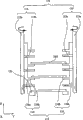
Fig. 9 is the enlarged drawing that pallet is moved into device and pallet conveyance device.
Figure 10 A is the simple cut-open view (its 1) that the expression pallet is moved into the common conveyance state of the test pallet that device forms.
Figure 10 B is the simple cut-open view (its 2) that the expression pallet is moved into the common conveyance state of the test pallet that device forms.
Figure 10 C is the simple cut-open view (its 3) that the expression pallet is moved into the common conveyance state of the test pallet that device forms.
Figure 10 D is the simple cut-open view (its 4) that the expression pallet is moved into the common conveyance state of the test pallet that device forms.
Figure 10 E is the simple cut-open view (its 5) that the expression pallet is moved into the common conveyance state of the test pallet that device forms.
Figure 11 A is the simple cut-open view (its 1) that the expression pallet is moved into the contrary conveyance state of the test pallet that device forms.
Figure 11 B is the simple cut-open view (its 2) that the expression pallet is moved into the contrary conveyance state of the test pallet that device forms.
Figure 11 C is the simple cut-open view (its 3) that the expression pallet is moved into the contrary conveyance state of the test pallet that device forms.
Figure 11 D is the simple cut-open view (its 4) that the expression pallet is moved into the contrary conveyance state of the test pallet that device forms.
Figure 11 E is the simple cut-open view (its 5) that the expression pallet is moved into the contrary conveyance state of the test pallet that device forms.
Description of reference numerals
[0032]
1... electronic component testing apparatus
100... case chamber portion
101... device base station
102... tray conveying device
110... heat absorption casing
111... vertical carrying device
119... pallet is moved into device
119b... contacting part
The portion 119c... stand
120... test casing
126... conveyance band
130... heat extraction casing
131... pallet conveyance device
131b... contacting part
The portion 131c... stand
132... vertical carrying device
200... storage part
300... loading part
400... unloading portion
5... measuring head
9... conveyer
TST... test pallet
720... recess
Embodiment
[0033] below, embodiments of the invention is described with reference to the accompanying drawings.
[0034] Fig. 1 is the simple cut-open view of the electronic component testing apparatus of the expression embodiment of the invention, Fig. 2 is the oblique view of electronic component testing apparatus of the expression embodiment of the invention, and Fig. 3 is the concept map that the pallet in the electronic component testing apparatus of the expression embodiment of the invention transmits.
[0035] have, Fig. 3 is the figure in order to the pallet transfer approach in the electronic component testing apparatus of understanding present embodiment again, the part that has among the figure with reality for up and down and the member plane earth of row arrangement illustrate.Therefore, with reference to Fig. 2 its machinery (three-dimensional) structure is described.
Whether [0036] electronic component testing apparatus 1 of present embodiment is subjected under the state of temperature stress of high temperature or low temperature the IC device, suitable with the action of measuring head 5 and test machine 6 test (inspection) IC devices, and based on this test result with the IC device classification.The IC device is changeed from client's pallet KST (with reference to Fig. 5) that many IC devices for tested object are housed install to the test pallet TST (with reference to Fig. 6) of circulation conveyance in processor 1 after, 1 pair of IC device of this electronic component testing apparatus is tested.Have, the IC device is represented with symbol IC in the drawings again.
[0037] as shown in Figure 1, be provided with space 8, in this space 8, dispose measuring head 5 convertibly in the bottom of processor 1.On measuring head 5, be provided with socket 50, be connected with test machine 6 by cable 7.And the peristome by forming on the device base station 101 of processor 1 electrically contacts the socket 50 on IC device and the measuring head 5, by the electric signal from test machine 6 the IC device is tested.Have again, carry out kind when exchange, change shape and the adaptive socket of number of pins with the IC device of this kind at the IC device.
[0038] as shown in Figures 2 and 3, the processor 1 in the present embodiment is made of storage part 200, loading part 300, case chamber portion 100 and unloading portion 400, the IC device that will test after storage part 200 stores, and will survey complete IC device classification and deposit; The IC device that loading part 300 is sent storage part 200 here is sent into case chamber portion 100; Case chamber portion 100 comprises measuring head 5; Unloading portion 400 will finish the survey of test and finish the taking-up of IC device classification in case chamber portion 100.In the present embodiment, with as shown in Figure 3 between loading part 300, heat absorption casing 110, test casing 120, heat extraction casing 130 and unloading portion 400 a series of mechanisms of circulation conveyance test pallet TST be generically and collectively referred to as conveyer 9.
[0039] below, describes with regard to the each several part of processor 1.
[0040]<storage part 200 〉
Fig. 4 is the exploded perspective view of the IC receptacle that uses in the electronic component testing apparatus of the expression embodiment of the invention, and Fig. 5 is the oblique view of client's pallet of using in the electronic component testing apparatus of the embodiment of the invention.
[0041] receptacle 201 was finished receptacle 202 with the survey of depositing the IC device of classifying by test result before storage part 200 was provided with and deposits the survey of surveying preceding IC device.
[0042] as shown in Figure 4, these receptacles 201,202 are provided with: the pallet bearing frame 203 of frame shape; And enter from the bottom of this pallet bearing frame 203 and to the lifter 204 of top lifting.On the pallet bearing frame 203, piling up has a plurality of client's pallet KST, and client's pallet KST that lifter 204 only will pile up moves up and down.Have again, as shown in Figure 5, be arranged with the concavity resettlement section that 14 row * 13 row are accommodated the IC device on client's pallet KST of present embodiment.
[0043] because receptacle 201 and survey and finish receptacle 202 and have same structure before surveying, can be separately as required quantity receptacle 201 is set before the survey of suitable number and surveys and finish receptacle 202.
[0044] as shown in Figures 2 and 3, in the present embodiment, be provided with 2 receptacle STK-B, be provided with 2 empty pallet receptacle STK-E with being adjacent as receptacle 201 before surveying.Pile up client's pallet KST that the sky of sending here from unloading portion 400 is arranged on each empty pallet receptacle STK-E.
[0045] adjacent with empty pallet receptacle STK-E, be provided with 8 receptacle STK-1, STK-2 ..., STK-8 can be divided into 8 classification at most by test result and carry out the stock as survey finishing receptacle 202, constituting.That is, except certified products and unacceptable product, can also in certified products, distinguish high, medium and low three classes of operating rate, perhaps in unacceptable product, distinguish the classification that to test again etc.
[0046]<loading part 300 〉
Fig. 6 is the exploded perspective view of the test pallet that uses in the electronic component testing apparatus of the expression embodiment of the invention.
[0047] above-mentioned client's pallet KST is by being located at tray conveying arm 205 between storage part 200 and the device base station 101 is transported to loading part 300 from the downside of device base station 101 2 window portion 370.Then, in this loading part 300, be loaded in IC device on client's pallet KST by the 310 temporary transient conveyances of device transferring device to precise localizer (preciser) 360, revise mutual alignment relation of IC device at this place.Then, carrying device 310 moves the IC device of conveyance to this aligner 360 once more, changes installing on the test pallet TST that docks at loading part 300.
[0048] as shown in Figure 6, parallel and uniformly-spaced be provided with horizontal stripe 702 on square box 701 among the test pallet TST, equally spaced outstanding respectively and form a plurality of installation sheets 703 on the side 701a of the both sides of these horizontal stripes 702 and the frame 701 relative with horizontal stripe 702.Between these horizontal stripes 702 or between horizontal stripe 702 and the side 701a, constitute insert resettlement section 704 by 2 installation sheets 703.
[0049] accommodate 1 insert 710 respectively on each insert resettlement section 704, these insert 710 usefulness securing members 705 are installed on 2 installation sheets 703 with floating state.For this reason, on the both ends of insert 710, form in order to this insert 710 is installed in the mounting hole 706 on the installation sheet 703.As shown in Figure 6,64 such inserts 710 are housed, line up 4 row, 16 row at 1 test pallet TST.
[0050] have, each insert 710 constitutes with same shape, same size, accommodates the IC device on each insert 710 again.The shape of the IC resettlement section of insert 710 is determined according to the shape of accommodating the IC device, forms square recess in example shown in Figure 6.
[0051] and, the back side at the frame 701 of the test pallet TST of present embodiment is formed with in order to move into the 119c of the portion of standing of device 119 and pallet conveyance device 131, the recess 720 (with reference to Fig. 7) that 131c engages with pallet.
[0052] loading part 300 is provided with changes the device transferring device 310 that installs to test pallet TST with the IC device from client's pallet KST.As shown in Figure 2, device transferring device 310 is by constituting as the lower part: be erected at 2 tracks 311 on the device base station 101; Can rely on these 2 tracks 311 between test pallet TST client pallet KST, to move back and forth the moveable arm 312 of (this direction that moves back and forth is the Y direction); And by these moveable arm 312 movable headstocks 320 that support, that can on X-direction, move.
[0053] on the movable headstock 320 of this device transferring device 310, suction tray (not shown) is housed down, adsorbing mobilely by this absorption headstock, keeping the IC device to forward this IC device to test pallet TST from client's pallet KST and piling up.For 1 movable headstock 320, suction tray such about 8 for example is housed, once 8 IC devices can be forwarded on the test pallet TST and pile up.
[0054]<case chamber portion 100 〉
Fig. 7 is the simple cut-open view of case chamber portion inside of the electronic component testing apparatus of the expression embodiment of the invention, Fig. 8 A~Fig. 8 I be from the VIII direction see vertical carrying device the heat absorption casing of the case chamber portion shown in Fig. 7 to view.
[0055] after loading onto the IC device by loading part 300, above-mentioned test pallet TST is admitted to case chamber portion 100, is equipped on the test of carrying out each IC device under the state of test pallet TST at the IC device.
[0056] as Fig. 2, Fig. 3 and shown in Figure 7, case chamber portion 100 is by constituting as the lower part: make the IC device that is loaded into test pallet TST be subjected to being made as the heat absorption casing 110 of the temperature stress of the high temperature of target or low temperature; The test casing 120 that the IC device that is in the state that is subjected to thermal stress in this heat absorption casing 110 is contacted with measuring head 5; And the heat extraction casing 130 that thermal stress is eliminated from the IC device of having done test in test the casing 120.
[0057] as shown in Figure 2, heat absorption casing 110 is given prominence to upward and is disposed from test casing 120.And, as shown in Figure 7, be provided with vertical carrying device 111, pallet is moved into device 119, protrusion tab 118 and sensor 1191 in the inside of this heat absorption casing 110.
[0058] vertical carrying device 111 is provided with the 1st supporting mechanism 112 and the 2nd supporting mechanism 115, on one side can be on one side between the 1st supporting mechanism 112 and the 2nd supporting mechanism 115 mutually handing-over test pallet TST, make test pallet TST decline.
[0059] shown in Fig. 8 A, the 1st supporting mechanism 112 is made of with the actuator (not shown) that this support member 113 is moved up and down and rotate 4 the 1st support member 113.Each the 1st support member 113 is by columned axle 113a with for flatly supporting test pallet TST to constitute from outstanding a plurality of (this example being 3) the branching portion 113b of axle 113a.Actuator makes the 1st support member 113 move up and down along the axle center of axle 113a and is the center rotation with this axle center.Have again, 2 the 1st support member 113 only are shown among Fig. 8 A.These 4 the 1st support member 113 are configuration relatively in twos, to support test pallet TST near each bight.A plurality of branching portion 113b mutually equally spaced and radially being located at highlightedly on the 112a towards axle 112a.
[0060] the 2nd supporting mechanism 115 is made of with the cylinder (not shown) that the 2nd support member 116 is moved in the Y direction 4 the 2nd support member 116.Each the 2nd support member 116 by with respect to the axle 113a of the 1st support member 113 abreast adjacency base portion 116a and from constituting in order to outstanding a plurality of (this example being 3) the teat 116b of the base portion 116a that flatly supports test pallet TST.Cylinder makes 4 the 2nd support member 116 each leisures with respect to moving on the vertical Y direction of the conveyance direction of test pallet TST.A plurality of teat 116b mutually equally spaced and radially being provided with highlightedly towards base portion 116a.Have again, 2 the 2nd support member 116 only are shown among Fig. 8 A.These 4 the 2nd holding componentss 116 dispose with respect to each teat 116b in twos, to support test pallet TST near each bight.
[0061] this vertical carrying device 111 is received test pallet TST from loading part 300 1, and shown in Fig. 8 A, just elder generation keeps test pallet TST by the teat 116b of the 2nd support member 116 of the 2nd supporting mechanism 115.
[0062] then, shown in Fig. 8 B, the 1st support member 113 of the 1st supporting mechanism 112 rises, and branching portion 113b accepts test pallet TST from the 2nd support member 116.The handing-over one of test pallet finishes, and the rising of the 1st support member 113 just finishes.
[0063] then, shown in Fig. 8 C, the 2nd support member 116 in opposite directions to separately from direction move.Then, the 2nd support member 116 is removed, and up to the position that the test pallet TST and the teat 116b of decline do not interfere with each other, stops moving at this place.
[0064] then, shown in Fig. 8 D, actuator makes supports the 1st support member 113 of test pallet TST to descend, thereby test pallet TST is reduced more.
[0065] then, approaching once more separately between the 2nd support member 116 in opposite directions shown in Fig. 8 E, up to the position of accepting this test pallet TST that falls.Then, shown in Fig. 8 F, the 1st support member 113 descends, and removes and the contacting of test pallet TST, and the test pallet TST that is supported by the branching portion 113b of minimum one-level in the 1st support member 113 is installed on the conveyance cylinder 117 by commentaries on classics, then to testing casing 120 conveyances.Other test pallets TST passes to the 2nd support member 116 from the 1st support member 113.Have, test pallet TST changes the riding position that installs on the conveyance cylinder 117 from the 1st support member 113 and is called the starting position again.
[0066] then, shown in Fig. 8 G, the 1st support member 113 is the axis half-twist with axle 113a, and the branching portion 113b of subtend becomes parallel in fact state mutually.
[0067] then, shown in Fig. 8 H, the 1st support member 113 rises.At this moment, the 1st support member 113 does not rise contiguously with test pallet TST.Then, shown in Fig. 8 I, the 1st support member 113 turns over equal angular with the direction opposite with the sense of rotation of Fig. 8 G, thereby the mutual once more subtend of branching portion 113b becomes the state that can keep test pallet TST.
[0068] have again, till the end of test (EOT) of test pallet TST that is introduced into test casing 120 during, these a plurality of test pallet TST support by this vertical carrying device 111 on one side, on one side standby in heat absorption casing 110.Mainly be in order to apply the thermal stress of high temperature or low temperature in this standby, for the IC device.
[0069] in addition, this vertical carrying device 111 also can rise test pallet TST to reduce opposite mode of operation with the above-mentioned test pallet TST that makes.
[0070] drops to the test pallet TST of the starting position on the conveyance cylinder 117 from vertical carrying device 111, move into conveyance band 126 in device 119 and the test casing, send in the test casing 120 by pallet.
[0071] shown in Fig. 9 and Figure 10 A, pallet move into device 119 by touch member 119a, the 119c of portion that stands, track 119g, conveyance cylinder 117 and cylinder 114 constitute.And, pallet move into device 119 will be equipped with survey before the test pallet TST of IC device from the 110 side conveyances of heat absorption casing to test casing 120 sides.In addition, as described later, can turn back to the starting position at the test pallet TST in test casing 120 side shiftings way during against conveyance.Under the driving force effect of cylinder 114, touching member 119a can slide on track 119g.
[0072] touches member 119a when having common conveyance and the contacting part 119b that touches of test pallet TST and restriction described later backstop 119d, the 119e that the 119c of portion moves that stand.Contacting part 119b is located at the right upper portion among the Fig. 9 that touches member 119a, and contacting part 119b is outstanding upward.Usually during conveyance, touch, test pallet TST is gone out to 120 thrusters of test casing with the end of heat absorption casing 110 sides in the end of test pallet TST.
[0073] backstop 119d, 119e are arranged in the directions X 119c of portion that will stand and surround, and are limited in the specialized range with the spinning movement of the 119c of portion that will stand.Particularly, during from the 120 side conveyances of heat absorption casing 110 side direction test casing, backstop 119d is used for being restricted to the action of the 119c of the portion of standing that does not interfere with test pallet TST with protrusion tab 118 described later and fall down at test pallet TST.In addition, backstop 119e is used for limiting the rotation of the 119c of portion of standing, so that standing of the 119c of portion that stands is about 90 degree to the maximum with respect to directions X.
[0074] 119c of portion that stands installs from touching member 119a upward highlightedly via axle 119h, can rotate touching on the member 119a, and relies on spring 119f to apply power towards backstop 119e side.Therefore, in the normal state, stand 119c of portion and backstop 119e touch, and become at Z to the state of standing.As described later, during the contrary conveyance of test pallet TST, this 119c of portion that stands is engaged in the recess 720 of test pallet TST, and TST back into the starting position with test pallet.Also have, this stand the 119c of portion and touch member 119a below, track 119g extends and establishes at directions X.
[0075] track 119g forms so-called linear guides with touching member 119a.This track 119g has pallet and moves into the length that device 119 can carry out common conveyance and the contrary conveyance of test pallet TST described later.Specifically as described later, track 119g has such length, makes that touching member 119b can move to the position that stops from the starting position when the 119c of portion that stands falls down because of touching protrusion tab 118.In addition, conveyance cylinder 117 is laid abreast with the bearing of trend of track 119g.
[0076] the not ad hoc drive source of conveyance cylinder 117 is moved into the test pallet TST that device 119 moves and is moved but accompany or follow by pallet.And cylinder 114 is located near the end of heat absorption casing 110 sides of conveyance cylinder 117.
[0077] cylinder 114 is can make to touch the driver part of member 119a in the X-direction advance and retreat.Have again, adopt cylinder 114 in the present embodiment, but driver part is not limited by this, for example also can adopt the motor that is provided with ball screw framework etc.
[0078] gets back to Fig. 7, protrusion tab 118 is located between 2 conveyance cylinders 117, near the terminal point of the conveyance path of the test pallet TST in the heat absorption casing 110, with by the conveyance test pallet TST and the member 119a that touches that moves do not interfere, and be located at can only with the 119c of the portion position contacting of standing.This protrusion tab 118 is to touch, make the portion 119c of standing to swing to the member of backstop 119d side mutually with the portion 119c of standing when moving into device 119 at pallet described later and carry out the conveyance of test pallet TST.
[0079] in addition, sensor 1191 is located near the starting position in the heat absorption casing 110, can detects the position that test pallet TST is in the starting position.
[0080] sensor 1191 is used for detecting test pallet TST whether by the starting position of vertical carrying device 111 carrying correctly to the cylinder 117, and stop up whether test pallet TST correctly gets back to the starting position by contrary conveyance when taking place, testing result is sent to control device 1287.The contrary conveyance situation of test pallet TST will describe in detail later when taking place about stopping up.
[0081] Figure 10 A~Figure 10 E is the simple cut-open view that the expression pallet is moved into the common conveyance state of the test pallet that device causes.Here, with reference to Figure 10 A~Figure 10 E, earlier the situation of moving into the common conveyance that device 119 causes with regard to above-mentioned pallet describes in detail, and the contrary conveyance of carrying out when taking place about the obstruction of test pallet TST is described further below.
[0082] at first, be applied in the test pallet TST of thermal stress in the casing 110, moved into the starting position on the conveyance cylinder 117 of device 119 by vertical carrying device 111 carryings to pallet in heat absorption.And if the end of test (EOT) of the test pallet TST that test advances into earlier in the casing 120, Z axial brake device 129 described later rises, then pallet move into device 119 will be equipped with survey before the test pallet TST of IC device to the 120 side conveyances of test casing.
[0083] in more detail, shown in Figure 10 A, when test pallet TST dropped on the conveyance cylinder 117, the 119c of the portion of standing that pallet is moved into device 119 inserted the recess 720 that the IC device that is formed at test pallet TST carries the face opposition side.Then, shown in Figure 10 B and Figure 10 C, cylinder 114 makes pallet move into device 119 when directions X moves, and contacting part 119b pushes test the rear end of test pallet TST to casing 120 sides.Thus, the center of gravity one of the test pallet TST that releases moves on the conveyance band 126 of test casing 120 sides described later from the conveyance cylinder 117 of heat absorption casing 110 sides, shown in Figure 10 D and Figure 10 E, just touch protrusion tab 118 with touching the mobile 119c of the portion of standing of member 119a, swing to backstop 119d side.So, the 119c of portion that stands withdraws from from the conveyance path of test pallet TST, avoids interfering with the 119c of portion that stands to the test pallet TST of test casing 120 side conveyances.
[0084] as mentioned above, in common conveyance, pallet is moved into device 119 center of gravity of the test pallet TST conveyance cylinder 117 from heat absorption casing 110 sides is moved on the conveyance band 126 of test casing 120 sides described later, thereby test pallet TST is moved into test casing 120 sides from heat absorption casing 110 sides.
[0085] as shown in Figure 7, be provided with in the test casing 120: the conveyance band 126 of conveyance test pallet TST; Be connected with control device 1287 and monitor the sensor 125 of the conveyance state of test pallet TST; The test pallet TST touching that comes with conveyance and pallet backstop 122 that the conveyance of test pallet TST is stopped on measuring head 5; And be contained in that IC device on the test pallet TST that stops touches and with the IC device by the Z axial brake device 129 that is pressed on the socket 50.
[0086] conveyance band 126 is the members that extend on directions X, drive by driver part (not shown) rotation, in can be when common conveyance with test pallet TST towards the directions X conveyance, and when contrary conveyance with test pallet TST towards the reverse direction conveyance opposite with directions X.In addition, this conveyance band 126 is used supports movably up and down such as spring member (not shown) especially, so that Z axial brake device 129 can move up and down when pushing IC device and test pallet TST.
[0087] sensor 125 be located on the directions X, between pallet backstop 122 and the socket 50, be used for confirming test pallet TST whether conveyance to going up the position that the IC device that carries is suitably tested to test pallet TST.The monitoring result of sensor 125 sends the control device 1287 that is connected with sensor 125 to.
[0088] pallet backstop 122 be located near the sensor 125, the position of interference testing pallet TST conveyance not.And pallet backstop 122 is members that test pallet TST is stopped at test position, can advance and retreat in the Y direction by actuators such as cylinder (not shown).Under situations such as IC device detection, when test pallet TST to stop, actuator makes pallet backstop 122 be projected into the position of touching with test pallet TST, and test pallet TST is stopped on the test position.And, when after end of test (EOT), test pallet TST being moved to the heat extraction casing, perhaps between test casing described later and heat extraction casing, taking place to stop up and when carrying out contrary conveyance, actuator makes pallet backstop 122 retreat into not position with test pallet TST touching.
[0089] in addition, the device base station bottom in test casing 120 is provided with peristome (not shown).Peristome has the size that measuring head 5 can enter its central portion when test.As shown in Figure 7, the top of measuring head 5 is provided with a plurality of sockets 50, disposes in opposite directions with the insert 710 of test pallet TST.Relative therewith, in the test casing 120, as shown in Figure 7, when being provided with test on each socket 50 on measuring head 5 respectively opposite to each other the IC device is pushed to a plurality of devices 1281 that push of socket 50.
[0090] each pushes device 1281 and is maintained on the matching disc 1282, and this matching disc 1282 can move up and down by Z axial brake device 129.
[0091] as shown in Figure 7, Z axial brake device 129 is provided with axle 1296, drive plate 1297 and protuberance 1298, moves up and down by actuator (not shown).
[0092] axle 1296 runs through the upper wall surface of testing casing 120, and its lower end is fixed on the drive plate 1297.Drive plate 1297 is established in opposite directions with matching disc 1282, is provided with the outstanding a plurality of protuberances 1298 of convex below it.These protuberances 1298 be configured in drive plate 1297 below, respectively with matching disc 1282 on the device 1281 that pushes that keeps establish in opposite directions.This protuberance 1298 is used for pushing when test and pushes device 1281.
[0093] test pallet TST moves into device 119 and conveyance band 126 by pallet and sends in the test casing 120 from heat absorption casing 110, this test pallet TST just immediately by conveyance to measuring head 5, respectively pushing device 1281 is pressed into the IC device on the socket 50 respectively, the input and output terminal of IC device and the haptic element of socket 50 are electrically contacted, thereby carry out the test of IC device.
[0094] this test result for example is stored in test pallet TST and goes up on the address that the numbering of the IC device of appended identiflication number and test pallet TST internal distribution determines.
[0095] test one of the IC device that go up to keep of test pallet TST finishes, test pallet TST just from tested casing 120 conveyances to heat extraction casing 130.Conveyance from test casing 120 to heat extraction casing 130 is undertaken by conveyance band 126 and pallet conveyance device 131.
[0096] particularly, at first the test pallet TST that surveys complete IC device will be housed and release heat extraction casing 130 sides from test casing 120 by conveyance band 126.Then, test pallet TST is submitted to the pallet conveyance device 131 of heat extraction casing 130.This pallet conveyance device 131 is with the assigned position of test pallet TST conveyance to heat extraction casing 130.
[0097] as shown in Figure 2, heat extraction casing 130 is the same with heat absorption casing 110, all is configured to give prominence to upward from test casing 120, as Fig. 3 and shown in Figure 7, is provided with pallet conveyance device 131, vertical carrying device 132, protrusion tab 138 and sensor 133.
[0098] shown in Fig. 9 and Figure 10 A, pallet conveyance device 131 by touch member 131a, the 131c of portion that stands, track 131g, conveyance cylinder 137 and cylinder 139 constitute, can be with test pallet TST conveyance on directions X.This pallet conveyance device 131 has with the pallet of heat absorption in the casing 110 moves into the identical structure of device 119, moves into device 119 with pallet and oppositely be provided with on directions X.Here omit its detailed description.
[0099] in addition, vertical carrying device 132 is identical with vertical carrying device 111 in the aforesaid heat absorption casing 110, therefore, omits its detailed description here.
[0100] in addition, protrusion tab 138 is between 2 conveyance cylinders 137, be located near the initial point of conveyance path of the test pallet TST in the heat extraction casing 130, not with by the test pallet TST of conveyance or mobile touch member 131a interference, and be configured in can only with the position of the 131c of the portion touching of standing on.This protrusion tab 138 is identical with the protrusion tab 118 of heat absorption in the casing 110, omits the detailed description about its structure and action here.
[0101] in addition, sensor 133 be located at pallet conveyance device 131 with test pallet TST near the terminal point of directions X conveyance, can monitor the position of the conveyance of test pallet TST.On this sensor 133, be connected with control device 1287.Sensor 133 be used for detecting test pallet TST whether from 120 conveyances of test casing to heat extraction casing 130, and whether test pallet TST turns back on the pallet conveyance device 131 from vertical carrying device 132 when contrary conveyance described later.Its testing result sends to control device 1287 from sensor 133.
[0102] if the IC device has been applied in high temperature at heat absorption casing 110, then in this heat extraction casing 130,, the IC device is cooled to room temperature by being blown.In contrast, if the IC device has been applied in low temperature at heat absorption casing 110, then, after getting back to the temperature that dewfall does not take place, this IC device by heat extraction is taken out of to unloading portion 400 with heating IC devices such as warm air heaters.
[0103] as previously mentioned, test pallet TST by conveyance band 126 from test casing 120 when 130 conveyances of heat extraction casing, the 131c of the portion of standing of pallet conveyance device 131 stands, and is bonded on the recess 720 at the back side that is positioned at test pallet TST.And under this state, pallet conveyance device 131 moves at linear guides upper edge directions X, thereby move on sliding limit in conveyance cylinder 137 tops, arrives the assigned position of heat extraction casing 130 until test pallet TST.
[0104] like this, test pallet TST one moves to assigned position, and pallet conveyance device 131 just stops.To make the opposite mode of operation of test pallet TST decline with aforesaid vertical carrying device 111, vertical carrying device 132 rises test pallet TST.
[0105], forms in order to move into the inlet of test pallet TST from device base station 101 on the top of heat absorption casing 110.Equally, on the top of heat extraction casing 130, form in order to test pallet TST is taken out of the outlet of auto levelizer base station 101.And, on device base station 101, be provided with in order to make test pallet TST go out the tray conveying device 102 of cartonning chamber portion 100 by these entrance and exits.This tray conveying device 102 is for example with formations such as swing rollers.
[0106] the test pallet TST that takes out of from heat extraction casing 130 by this tray conveying device 102, finishing the IC device in the survey of will be carried is forwarded to by device transferring device 410 as described later and piles up on client's pallet KST and after being vacateed, be returned to heat absorption casing 110 via unloading portion 400 and loading part 300.
[0107]<unloading portion 400 〉
In the present embodiment, also be provided with in the unloading portion 400 2 with loading part 300 on the carrying device 410 of set device transferring device 310 same structures, will survey by this device transferring device 410 and to finish the IC device and pile up from transporting the client's pallet KST that forwards to corresponding to test result to the test pallet TST of unloading portion 400.
[0108] as shown in Figure 2, on the device base station 101 of unloading portion 400, be formed with two and form right window portion 470, on it, face the top of device base station 101 and configuration is transported into client's pallet KST of unloading portion 400 from storage part 200.
[0109] in addition, be provided with the lifting table (diagram slightly) that makes client's pallet KST lifting, changeed the survey of dress in this place carrying and finish client's pallet KST decline that the IC device piles with, and give tray conveying arm 205 this loaded pallets at the downside of each window portion 470.
[0110] then, the contrary conveyance when taking place to stop up with regard to test pallet TST and eliminate the order of the obstruction that conveyance again causes is an example with the situation that obstruction takes place from heat absorption casing 110 to the conveyance of test casing 120, describes with Fig. 7 and Figure 11 A~11E.
[0111] Figure 11 A~11E is that expression is moved into the simple cut-open view that device 119 is carried out the contrary conveyance of test pallet TST by pallet of the present invention.
[0112] shown in Figure 11 A, when test pallet TST drops on the conveyance cylinder 117, inserts the 119c of the portion of standing that pallets are moved into device 119 at the recess 720 of the lift-launch face opposition side of the IC device that is formed at test pallet TST.Then, shown in Figure 11 B, drive tray conveying device 119 when directions X moves by cylinder 114, contacting part 119b goes out the rear end of test pallet TST to 120 thrusters of test casing.
[0113] when this conveyance, shown in Figure 11 C, as if the obstructions that test pallet TST take place in the heat absorption casing 110, test pallet TST then tests the conveyance that casing 120 interior set sensors 125 just can not be confirmed test pallet TST not to 120 conveyances of test casing.Therefore, can not transmit the information that test pallet TST arrives to control device 1287.Like this, if not sending the common conveyance that state that test pallet TST arrives information moves into device 119 from pallet, sensor 125 do not begin to last till the stipulated time that control device 1287 just recognizes in the heat absorption casing 110 and stops up.
[0114] have again, also can be according to the sensor of the elongation that detects cylinder 114, according to detecting the detection of stopping up generation less than the situation of this elongation at the appointed time.
[0115] obstruction one of test pallet TST is identified, and control device 1287 is just moved into device 119 to pallet and sent the instruction of carrying out contrary conveyance.At this moment, in the recess 720 of test pallet TST, the portion 119 of standing still is in the insertion state.In addition, if be necessary, control device 1287 makes the position beyond the conveyer 9 raising middle flask chamber portions 100 stop to drive, and is eliminated up to obstruction.
[0116] then, receive the pallet of the instruction of carrying out contrary conveyance and move into device 119, cylinder 114 is driven, test pallet TST is moved from the position court-directions X that stops up.When this contrary conveyance, shown in Figure 11 D, remove touching of test pallet TST and contacting part 119b, replace the inwall that the 119c of the portion of standing by insertion recess 720 touches recess 720 and promote, make test pallet TST turn back to the starting position.
[0117] then, shown in Figure 11 E, if test pallet TST has got back to the starting position, sensor 1191 just perceives this situation, and sends this information to control device 1287.Control device 1,287 one is received the information of getting back to the starting position about test pallet TST of sensor 1191, just pallet is moved into device 119 and sends and carry out the indication of conveyance test pallet TST again.Receive this indication, pallet move into device 119 just once more with test pallet TST from heat absorption casing 110 to the 120 side conveyances of test casing.Thereby test casing 120 is arrived by normal conveyance in the position of test pallet TST by stopping up just now.In addition, control device 1287 drives the position beyond the case chamber portion 100 that was stopped just now in the conveyer 9 again and drives.
[0118] like this, with test pallet TST temporary transient contrary conveyance from the position that takes place to stop up, and conveyance again, stop up thereby eliminate.And, stop up to eliminate and automatically carry out, do not need manual recovery operation, therefore can reduce the loss of time.
[0119] have, more than Shuo Ming embodiment describes for the present invention is understood easily, is not for the present invention is limited again.Thereby disclosed each key element in the foregoing description comprises the whole design alterations that belong to technical scope of the present invention or is equal to key element.
[0120] for example, in the above-described embodiments, when being described from 110 conveyances of heat absorption casing to test casing 120, test pallet TST takes place to stop up and the situation of contrary conveyance, still, in the time of also can between test casing 120 and heat extraction casing 130, taking place to stop up, in heat extraction casing 130, carry out contrary conveyance.
[0121] in this case, test pallet TST in heat extraction casing 130 begins to have passed through from conveyance and fixes time and sensor 133 does not send in the information that test pallet TST have arrived to control device 1287, and control device 1287 just identifies in the heat extraction casing 130 obstruction has taken place.
[0122] the contrary conveyance of this situation, the pallet conveyance device 131 of use heat extraction casing 130.That is, against conveyance the time, pallet conveyance device 131 accepts to carry out the indication of contrary conveyance from control device 1287.Then, the contacting part 131b of pallet conveyance device 131 can release pallet towards the direction opposite with directions X.In this case, when the center of gravity of test pallet TST moves on to test casing 120 sides, the 131c of portion that stands push over protrusion tab 138 touchings to contacting part 131c not with the position of test pallet TST interference, the conveyance of test pallet TST is smoothly carried out.
[0123] in addition, according to the situation of stopping up, sometimes need a plurality of test pallet TST in the case chamber portion 100 are carried out contrary conveyance, at this moment, except above-mentioned pallet is moved into device 119 and pallet conveyance device 131, can use vertical carrying device 111,132 and tray conveying device 102, carry out contrary conveyance by whole conveyer 9.In this case, vertical carrying device 111,132 and tray conveying device 102 with the mode of operation opposite with common conveyance with the contrary conveyance of test pallet TST.
[0124] in addition, in the foregoing description, illustrated and only carried out the contrary conveyance of a test pallet TST and the situation of conveyance again, still, once can not also can repeatedly carry out contrary conveyance and conveyance again stopping up when eliminating.In addition, do not eliminate under the situation about stopping up yet after the conveyance again, can give a warning in the contrary conveyance that has repeated stipulated number.
Claims (13)
1. electronic component testing apparatus is used for making under tested electronic component is equipped on the state of pallet the contact site of described tested electronic component and measuring head to electrically contact and carries out the test of described tested electronic component, wherein:
Be provided with in described electronic component testing apparatus conveyer towards the described pallet of prescribed direction circulation conveyance,
Described conveyer can be towards the reverse direction opposite with the described prescribed direction described pallet of conveyance integrally or partly.
2. electronic component testing apparatus according to claim 1, wherein,
Described electronic component testing apparatus also is provided with:
Detect the unusual detection part of conveyance of the described pallet in the described conveyer; And
Carry out the control assembly of the action control of described conveyer,
Detect under the unusual situation of the conveyance of described pallet at described detection part, described control assembly is controlled described conveyer, makes described conveyer towards the described reverse direction described pallet of conveyance integrally or partly.
3. electronic component testing apparatus according to claim 2, wherein,
Described conveyer also is provided with integrally or is partly discerning the identification component whether described pallet has got back to assigned position during the described pallet of conveyance towards described reverse direction.
4. electronic component testing apparatus according to claim 3, wherein,
Identify described pallet at described identification component and got back under the situation of described assigned position, described control assembly is controlled described conveyer, makes described conveyer towards the described pallet of described prescribed direction conveyance.
5. according to the described electronic component testing apparatus of claim 1~4, wherein,
Described electronic component testing apparatus is provided with:
Tested electronic component before testing is applied the endothermic section of regulation thermal stress; And
The test department that the described tested electronic component that is applied in thermal stress is tested,
Described conveyer comprises:
Be located at the parts of moving in the described endothermic section, that described pallet moved into described test department; And
Be located at conveyance member in the described test department, the described pallet of conveyance,
The described parts of moving into can be towards the described pallet of described reverse direction conveyance.
6. electronic component testing apparatus according to claim 5, wherein,
The described parts of moving into comprise:
Touch with described pallet and towards the 1st contacting part of the described pallet of described prescribed direction conveyance; And
Towards the described pallet of described reverse direction conveyance the time and described pallet touch and towards the 2nd contacting part of the described pallet of described reverse direction conveyance.
7. according to the described electronic component testing apparatus of claim 1~4, wherein,
Described electronic component testing apparatus is provided with:
The test department that the described tested electronic component that is applied in thermal stress in the endothermic section is tested; And
The heat extraction portion that the described regulation thermal stress that is applied on the described tested electronic component that test is finished is eliminated,
Described conveyer comprises:
Be located at conveyance member in the described test department, the described pallet of conveyance; And
Be located in the described heat extraction portion, take out of the parts of taking out of of described pallet from described test department,
The described parts of taking out of can be towards the described pallet of described reverse direction conveyance.
8. electronic component testing apparatus according to claim 7, wherein,
The described parts of taking out of comprise:
Touch with described pallet and towards the 1st contacting part of the described pallet of described prescribed direction conveyance; And
Towards the described tray conveying of described reverse direction the time, touch with described pallet and towards the 2nd contacting part of the described pallet of described reverse direction conveyance.
9. tray conveying method,
Be used for being equipped under the state of pallet, electrically contact at the contact site that makes described tested electronic component and measuring head and carry out the described pallet of conveyance in the electronic component testing apparatus of test of described tested electronic component at tested electronic component,
In described electronic component testing apparatus in the conveyer of the described pallet of prescribed direction circulation conveyance, towards the reverse direction opposite described pallet of conveyance integrally or partly with described prescribed direction.
10. tray conveying method according to claim 9 comprises the steps:
Detect the unusual detection step of conveyance of pallet described in the described conveyer; And
According to the testing result of described detection step, described conveyer is towards the described reverse direction contrary conveyance step of the described pallet of conveyance integrally or partly.
11. tray conveying method according to claim 10 also comprises the steps:
Integrally or partly during the described pallet of conveyance, discern the identification step whether described pallet has got back to assigned position towards described reverse direction at described conveyer; And
According to the recognition result of described identification step, described conveyer is towards the conveyance step again of the described pallet of described prescribed direction conveyance.
12. according to claim 10 or 11 described tray conveying methods, wherein,
Described electronic component testing apparatus is provided with:
Described tested electronic component before testing is applied the endothermic section of regulation thermal stress; And
The test department that the described tested electronic component that is applied in thermal stress is tested,
In the described detection step, the conveyance that detects the described pallet that takes place at least one side in described endothermic section and the described test department is unusual,
In the described contrary conveyance step, with described pallet from described test department conveyance to described endothermic section.
13. according to claim 10 or 11 described tray conveying methods, wherein,
Described electronic component testing apparatus is provided with:
The test department that the tested electronic component that is applied in thermal stress in the endothermic section is tested; And
The heat extraction portion that the described regulation thermal stress that is applied on the described tested electronic component that test is preceding is eliminated,
In described detection step, the conveyance that detects the described pallet that takes place at least one side of described test department and described heat extraction portion is unusual,
In the described contrary conveyance step, with described pallet from the conveyance of described heat extraction portion to described test department.
Applications Claiming Priority (1)
| Application Number | Priority Date | Filing Date | Title |
|---|---|---|---|
| PCT/JP2006/325542 WO2008075439A1 (en) | 2006-12-21 | 2006-12-21 | Electronic component testing equipment and method of testing electronic component |
Publications (1)
| Publication Number | Publication Date |
|---|---|
| CN101563620A true CN101563620A (en) | 2009-10-21 |
Family
ID=39536078
Family Applications (1)
| Application Number | Title | Priority Date | Filing Date |
|---|---|---|---|
| CNA2006800567097A Pending CN101563620A (en) | 2006-12-21 | 2006-12-21 | Electronic component testing equipment and method of testing electronic component |
Country Status (5)
| Country | Link |
|---|---|
| JP (1) | JP5022381B2 (en) |
| KR (1) | KR101158064B1 (en) |
| CN (1) | CN101563620A (en) |
| TW (1) | TW200827726A (en) |
| WO (1) | WO2008075439A1 (en) |
Cited By (4)
| Publication number | Priority date | Publication date | Assignee | Title |
|---|---|---|---|---|
| CN103185813A (en) * | 2011-12-28 | 2013-07-03 | 株式会社爱德万测试 | Electronic device transfer apparatus, electronic device handling apparatus, and electronic device testing apparatus |
| CN103852710A (en) * | 2012-11-29 | 2014-06-11 | 鸿劲科技股份有限公司 | Contrapositive electronic-assembly operating device |
| TWI624672B (en) * | 2011-09-06 | 2018-05-21 | 精工愛普生股份有限公司 | Handler and part inspection apparatus |
| CN111153129A (en) * | 2018-11-07 | 2020-05-15 | 泰克元有限公司 | Carrying machine |
Families Citing this family (7)
| Publication number | Priority date | Publication date | Assignee | Title |
|---|---|---|---|---|
| JP5840403B2 (en) * | 2011-07-11 | 2016-01-06 | オリオン機械株式会社 | Environmental test equipment |
| KR101644481B1 (en) * | 2011-12-08 | 2016-08-02 | (주)테크윙 | Test handler |
| KR102254494B1 (en) * | 2015-04-30 | 2021-05-24 | (주)테크윙 | Handler for testing semiconductor device |
| KR102252638B1 (en) * | 2015-05-04 | 2021-05-17 | (주)테크윙 | Insert for test handler |
| CN105548787B (en) * | 2015-11-30 | 2018-12-28 | 东莞市冠佳电子设备有限公司 | Power module ATS |
| KR102461321B1 (en) * | 2017-08-18 | 2022-11-02 | (주)테크윙 | Handler for testing electro devices |
| JP2022021239A (en) * | 2020-07-21 | 2022-02-02 | 株式会社アドバンテスト | Electronic component handling device and electronic component testing device |
Family Cites Families (4)
| Publication number | Priority date | Publication date | Assignee | Title |
|---|---|---|---|---|
| JPH079825U (en) * | 1993-06-16 | 1995-02-10 | 村田機械株式会社 | Conveyor device with retry function |
| JPH1138083A (en) * | 1997-07-14 | 1999-02-12 | Advantest Corp | Ic test handler |
| JP4164182B2 (en) * | 1999-01-11 | 2008-10-08 | 株式会社アドバンテスト | Tray transfer device |
| SG102563A1 (en) * | 1999-01-11 | 2004-03-26 | Advantest Corp | Testing apparatus for electronic device board |
-
2006
- 2006-12-21 WO PCT/JP2006/325542 patent/WO2008075439A1/en active Application Filing
- 2006-12-21 CN CNA2006800567097A patent/CN101563620A/en active Pending
- 2006-12-21 KR KR1020097013594A patent/KR101158064B1/en active IP Right Grant
- 2006-12-21 JP JP2008550028A patent/JP5022381B2/en not_active Expired - Fee Related
-
2007
- 2007-11-19 TW TW096143670A patent/TW200827726A/en unknown
Cited By (7)
| Publication number | Priority date | Publication date | Assignee | Title |
|---|---|---|---|---|
| TWI624672B (en) * | 2011-09-06 | 2018-05-21 | 精工愛普生股份有限公司 | Handler and part inspection apparatus |
| TWI655445B (en) * | 2011-09-06 | 2019-04-01 | 日商精工愛普生股份有限公司 | Handler and part inspection apparatus |
| CN103185813A (en) * | 2011-12-28 | 2013-07-03 | 株式会社爱德万测试 | Electronic device transfer apparatus, electronic device handling apparatus, and electronic device testing apparatus |
| CN103185813B (en) * | 2011-12-28 | 2016-05-11 | 株式会社爱德万测试 | Electronic component shifting apparatus, electronic component operating means and electronic component testing apparatus |
| CN103852710A (en) * | 2012-11-29 | 2014-06-11 | 鸿劲科技股份有限公司 | Contrapositive electronic-assembly operating device |
| CN111153129A (en) * | 2018-11-07 | 2020-05-15 | 泰克元有限公司 | Carrying machine |
| CN111153129B (en) * | 2018-11-07 | 2021-11-05 | 泰克元有限公司 | Carrying machine |
Also Published As
| Publication number | Publication date |
|---|---|
| WO2008075439A1 (en) | 2008-06-26 |
| JP5022381B2 (en) | 2012-09-12 |
| KR20090095617A (en) | 2009-09-09 |
| JPWO2008075439A1 (en) | 2010-04-08 |
| KR101158064B1 (en) | 2012-06-18 |
| TW200827726A (en) | 2008-07-01 |
| TWI359273B (en) | 2012-03-01 |
Similar Documents
| Publication | Publication Date | Title |
|---|---|---|
| CN101563620A (en) | Electronic component testing equipment and method of testing electronic component | |
| US9586760B2 (en) | Electronic component transfer shuttle | |
| CN101368994B (en) | Apparatus for testing system-in-package devices | |
| CN100520426C (en) | Insert, tray, and electronic component handling device for electronic component-handling device | |
| CN101088017A (en) | Plug-in, pusher for electronic component conveying device, socket guide piece for test and electronic component conveying device | |
| CN101071784B (en) | Probing apparatus and probing method | |
| TWI506287B (en) | A probe card conveying mechanism, a probe card conveying method and a probe device | |
| JPH10232262A (en) | Testing conveyor for semiconductor device | |
| TW201333497A (en) | Electronic device testing apparatus | |
| KR20110018426A (en) | Electronic component testing method, insert, tray, and electronic component testing apparatus | |
| US9069010B2 (en) | Pitch changing apparatus, electronic device handling apparatus, and electronic device testing apparatus | |
| KR101386331B1 (en) | Wafer transfer device | |
| CN101849190B (en) | Insert, tray and electronic component testing apparatus | |
| CN101384913A (en) | Electronic part test apparatus and electronic part test method | |
| CN101334446A (en) | Device and method for transferring test trays and a handler having same, process for manufacturing semiconductor device | |
| CN110610874A (en) | Material storage device | |
| CN101842712B (en) | Insert, tray and electronic component testing apparatus | |
| KR101104291B1 (en) | Tray transfer apparatus and electronic component testing apparatus provided with the same | |
| CN110692129A (en) | Apparatus and method for testing semiconductor device | |
| JPWO2008142752A1 (en) | Tray storage device and electronic component testing device | |
| CN100526896C (en) | Pusher and electronic component handling device | |
| CN101368993B (en) | Apparatus for testing micro sd devices | |
| JP5137965B2 (en) | Conveying device and electronic component handling device | |
| KR100980210B1 (en) | Apparatus of transferring a test tray and Test Handler using the same | |
| TW200841015A (en) | Method for testing system-in-package devices |
Legal Events
| Date | Code | Title | Description |
|---|---|---|---|
| C06 | Publication | ||
| PB01 | Publication | ||
| C10 | Entry into substantive examination | ||
| SE01 | Entry into force of request for substantive examination | ||
| C02 | Deemed withdrawal of patent application after publication (patent law 2001) | ||
| WD01 | Invention patent application deemed withdrawn after publication |
Open date: 20091021 |