BR112014032152B1 - ABRASIVE PARTICLES HAVING PARTICULAR FORMATS AND ABRASIVE ARTICLES - Google Patents
ABRASIVE PARTICLES HAVING PARTICULAR FORMATS AND ABRASIVE ARTICLES Download PDFInfo
- Publication number
- BR112014032152B1 BR112014032152B1 BR112014032152-3A BR112014032152A BR112014032152B1 BR 112014032152 B1 BR112014032152 B1 BR 112014032152B1 BR 112014032152 A BR112014032152 A BR 112014032152A BR 112014032152 B1 BR112014032152 B1 BR 112014032152B1
- Authority
- BR
- Brazil
- Prior art keywords
- molded
- abrasive particles
- height
- molded abrasive
- abrasive particle
- Prior art date
Links
Images


Classifications
-
- C—CHEMISTRY; METALLURGY
- C09—DYES; PAINTS; POLISHES; NATURAL RESINS; ADHESIVES; COMPOSITIONS NOT OTHERWISE PROVIDED FOR; APPLICATIONS OF MATERIALS NOT OTHERWISE PROVIDED FOR
- C09K—MATERIALS FOR MISCELLANEOUS APPLICATIONS, NOT PROVIDED FOR ELSEWHERE
- C09K3/00—Materials not provided for elsewhere
- C09K3/14—Anti-slip materials; Abrasives
- C09K3/1409—Abrasive particles per se
-
- B—PERFORMING OPERATIONS; TRANSPORTING
- B01—PHYSICAL OR CHEMICAL PROCESSES OR APPARATUS IN GENERAL
- B01J—CHEMICAL OR PHYSICAL PROCESSES, e.g. CATALYSIS OR COLLOID CHEMISTRY; THEIR RELEVANT APPARATUS
- B01J2/00—Processes or devices for granulating materials, e.g. fertilisers in general; Rendering particulate materials free flowing in general, e.g. making them hydrophobic
- B01J2/22—Processes or devices for granulating materials, e.g. fertilisers in general; Rendering particulate materials free flowing in general, e.g. making them hydrophobic by pressing in moulds or between rollers
-
- B—PERFORMING OPERATIONS; TRANSPORTING
- B01—PHYSICAL OR CHEMICAL PROCESSES OR APPARATUS IN GENERAL
- B01J—CHEMICAL OR PHYSICAL PROCESSES, e.g. CATALYSIS OR COLLOID CHEMISTRY; THEIR RELEVANT APPARATUS
- B01J2/00—Processes or devices for granulating materials, e.g. fertilisers in general; Rendering particulate materials free flowing in general, e.g. making them hydrophobic
- B01J2/26—Processes or devices for granulating materials, e.g. fertilisers in general; Rendering particulate materials free flowing in general, e.g. making them hydrophobic on endless conveyor belts
-
- C—CHEMISTRY; METALLURGY
- C09—DYES; PAINTS; POLISHES; NATURAL RESINS; ADHESIVES; COMPOSITIONS NOT OTHERWISE PROVIDED FOR; APPLICATIONS OF MATERIALS NOT OTHERWISE PROVIDED FOR
- C09K—MATERIALS FOR MISCELLANEOUS APPLICATIONS, NOT PROVIDED FOR ELSEWHERE
- C09K3/00—Materials not provided for elsewhere
- C09K3/14—Anti-slip materials; Abrasives
- C09K3/1436—Composite particles, e.g. coated particles
-
- Y—GENERAL TAGGING OF NEW TECHNOLOGICAL DEVELOPMENTS; GENERAL TAGGING OF CROSS-SECTIONAL TECHNOLOGIES SPANNING OVER SEVERAL SECTIONS OF THE IPC; TECHNICAL SUBJECTS COVERED BY FORMER USPC CROSS-REFERENCE ART COLLECTIONS [XRACs] AND DIGESTS
- Y10—TECHNICAL SUBJECTS COVERED BY FORMER USPC
- Y10T—TECHNICAL SUBJECTS COVERED BY FORMER US CLASSIFICATION
- Y10T428/00—Stock material or miscellaneous articles
- Y10T428/29—Coated or structually defined flake, particle, cell, strand, strand portion, rod, filament, macroscopic fiber or mass thereof
- Y10T428/2982—Particulate matter [e.g., sphere, flake, etc.]
Abstract
PARTÍCULAS ABRASIVAS TENDO FORMATOS PARTICULARES E MÉTODOS PARA FORMAR TAIS PARTÍCULAS. Partículas abrasivas moldadas incluindo um corpo tendo um comprimento (I), uma largura (w), um altura interior (hi), em que a altura é pelo menos cerca de 28% da largura, e uma porcentagem de flashing (f) de pelo menos cerca de 10% e não mais que cerca de 45% para uma área lateral total de um corpo.ABRASIVE PARTICLES HAVING PARTICULAR SHAPES AND METHODS FOR FORMING SUCH PARTICLES. Shaped abrasive particles including a body having a length (I), a width (w), an interior height (hi), wherein the height is at least about 28% of the width, and a flashing percentage (f) of at least less than about 10% and not more than about 45% for a total lateral area of a body.
Description
[001] A seguinte divulgação diz respeito a artigos abrasivos e, particularmente, métodos para formar partículas abrasivas.[001] The following disclosure relates to abrasive articles, and particularly methods for forming abrasive particles.
[002] Partículas abrasivas e artigos abrasivos feitos de partículas abrasivas são úteis para várias operações de remoção de material, incluindo moagem, acabamento e polimento. Dependendo do tipo de material abrasivo, tais partículas abrasivas podem ser úteis em moldar ou moer uma ampla variedade de materiais e superfícies na fabricação de mercadorias. Certos tipos de partículas abrasivas têm sido formulados até esta data que tenham geometrias particulares, tais como partículas ou artigos abrasivos com formato de triângulo incorporando tais objetos. Ver, por exemplo, Pat. US N° 5.201.916; 5.366.523; e 5.984.988.[002] Abrasive particles and abrasive articles made from abrasive particles are useful for various material removal operations including grinding, finishing and polishing. Depending on the type of abrasive material, such abrasive particles can be useful in shaping or grinding a wide variety of materials and surfaces in the manufacture of goods. Certain types of abrasive particles have been formulated to date that have particular geometries, such as triangle shaped abrasive particles or articles incorporating such objects. See, for example, U.S. Pat. US No. 5,201,916; 5,366,523; and 5,984,988.
[003] Três tecnologias têm sido empregadas para produzir partículas abrasivas com um formato específico, são elas (1) fusão, (2) sinterização, e (3) cerâmica química. No processo de fusão, a partícula abrasiva pode ser moldada por um cilindro de resfriamento, do qual a face pode ou não estar gravada, um molde no qual o material fundido é derramado, ou um material de dissipador de calor imerso em uma massa fundida de óxido de alumínio. Ver, por exemplo, Pat. US N° 3.377.660, que divulga um processo que compreende as etapas de fluir um material abrasivo fundido de uma fornalha a um cilindro de moldagem rotatório resfriado, rapidamente solidificado o material para formar uma folha curva semissólida e fina, densificando o material semissólido com um rolo de pressão, e então parcialmente fraturando a tira de material semissólido invertendo a sua curvatura ao puxar ele para longe do cilindro impulsionando rapidamente um transmissor resfriado.[003] Three technologies have been employed to produce abrasive particles with a specific shape, they are (1) melting, (2) sintering, and (3) chemical ceramics. In the melting process, the abrasive particle may be shaped by a quench cylinder, of which the face may or may not be engraved, a mold into which the molten material is poured, or a heat sink material immersed in a molten mass of aluminum oxide. See, for example, U.S. Pat. U.S. No. 3,377,660, which discloses a process comprising the steps of flowing a molten abrasive material from a furnace to a cooled rotating molding cylinder, rapidly solidifying the material to form a thin semi-solid curved sheet, densifying the semi-solid material with a pressure roller, and then partially fracturing the strip of semi-solid material by reversing its curvature by pulling it away from the cylinder rapidly propelling a cooled transmitter.
[004] No processo de sinterização, partículas abrasivas podem ser formadas de pó refratário, tendo um tamanho de partícula de até 10 micrômetros de diâmetro. Ligantes podem ser adicionados ao pó junto com um lubrificante e um solvente adequado, e.g., água. As misturas, misturas resultantes ou pastas fluídas podem ser moldadas em plaquetas ou varetas de diversos tamanhos e diâmetros. Ver, por exemplo, Pat. US N° 3.079.242, que divulga um método de produzir partículas abrasivas de a partir de material de brauxite calcinado, compreendendo as etapas de (1) reduzir o material a um pó fino, (2) compactar sob pressão afirmativa e formaras partículas finas do referido pó em aglomerados do tamanho de grãos, e (3) sinterizar os aglomerados de partículas a uma temperatura abaixo da temperatura de fusão do brauxite para induzir uma recristalização limitada das partículas, em que os grãos abrasivos são produzidos diretamente ao tamanho.[004] In the sintering process, abrasive particles can be formed from refractory powder, having a particle size of up to 10 micrometers in diameter. Binders can be added to the powder along with a lubricant and a suitable solvent, e.g., water. The mixtures, resulting mixtures or slurries can be molded into pellets or sticks of various sizes and diameters. See, for example, U.S. Pat. US No. 3,079,242, which discloses a method of producing abrasive particles from calcined brauxite material, comprising the steps of (1) reducing the material to a fine powder, (2) compacting under affirmative pressure and forming fine particles of said powder into grain-sized agglomerates, and (3) sintering the particle agglomerates at a temperature below the melting temperature of brauxite to induce limited recrystallization of the particles, whereby abrasive grains are produced directly to size.
[005] A tecnologia cerâmica química envolve a conversão de um dispersor coloidal ou hidrosol (as vezes chamado de a sol), opcionalmente em uma mistura, com soluções de outros precursores de óxido de metal, para um gel ou qualquer outro estado físico que restringe a mobilidade dos componentes, a secagem, e a queima para obter um material cerâmico. Ver, por exemplo, Pat. US N° 4.744.802 e 4.848.041.[005] Chemical ceramic technology involves converting a colloidal disperser or hydrosol (sometimes called a sol), optionally in a mixture, with solutions of other metal oxide precursors, to a gel or any other physical state that restricts component mobility, drying, and firing to obtain a ceramic material. See, for example, U.S. Pat. US Nos. 4,744,802 and 4,848,041.
[006] Ainda permanece uma necessidade na indústria para melhorar o desempenho, vida e eficácia de partículas abrasivas, e os artigos abrasivos que usam partículas abrasivas.[006] There still remains a need in the industry to improve the performance, life and effectiveness of abrasive particles, and the abrasive articles that use abrasive particles.
[007] Um método para formar um artigo abrasivo compreendendo o fornecimento de uma mistura em um substrato, formando a mistura em uma partícula abrasiva em formato precursor, compreendendo um corpo ao posicionar a mistura em uma abertura de uma tela, e separar a tela de uma correia subjacente, em que o processo de posicionar e remover são completados de forma substancialmente simultânea[007] A method for forming an abrasive article comprising providing a mixture on a substrate, forming the mixture into an abrasive particle in precursor format, comprising a body by positioning the mixture in an opening of a screen, and separating the screen from an underlying belt, in which the process of positioning and removing are completed substantially simultaneously
[008] Um lote de partículas abrasivas moldadas compreendendo, um comprimento media (I), uma largura mediana (w), uma altura interior mediana (hi), em que a altura interior mediana (hi) é pelo menos 28% da largura, e uma variação de altura interior (Vhi) não maior que 60 mícrons, e um percentual médio de flashing (f) de pelo menos cerca de 10% e não maior que cerca de 45% da área lateral total do corpo.[008] A batch of molded abrasive particles comprising, an average length (I), a median width (w), an interior median height (hi), where the median interior height (hi) is at least 28% of the width, and an interior height variation (Vhi) not greater than 60 microns, and an average percent flashing (f) of at least about 10% and not greater than about 45% of the total lateral body area.
[009] Um artigo abrasivo que compreende um apoio, uma pluralidade de partículas moldadas abrasivas sob o apoio, a pluralidade de partículas abrasivas moldadas sendo definidas pelo comprimento mediano (l), uma largura mediana (w), e uma altura interior media (hi), em que a altura interior mediana (hi) é pelo menos cerca de 28% da largura, e um percentual de flashing (f) é pelo menos cerca de 10% e não maior do que cerca de 45% do total da área lateral do corpo.[009] An abrasive article comprising a backing, a plurality of molded abrasive particles under the backing, the plurality of molded abrasive particles being defined by a median length (l), a median width (w), and an average interior height (hi ), in which the median interior height (hi) is at least about 28% of the width, and a flashing percentage (f) is at least about 10% and not greater than about 45% of the total lateral area of the body.
[010] A maioria da pluralidade de partículas abrasivas são orientadas em uma orientação predeterminada, respeito ao apoio, em que a orientação predeterminada é em uma orientação plana com relação ao apoio, em que a orientação predeterminada é uma orientação lateral com relação ao apoio, em que a orientação predeterminada está em um orientação inversa com relação ao apoio, em que pelo menos 55% da pluralidade das partículas abrasivas moldadas estão em uma orientação plana, uma orientação lateral, ou uma orientação invertida, em que pelo menos 60%, pelo menos 65%, pelo menos 70%, pelo menos 75%, pelo menos 77%, pelo menos 80%, pelo menos 81%, pelo menos 82%, e não maior que cerca de 99%.[010] Most of the plurality of abrasive particles are oriented in a predetermined orientation with respect to the backing, where the predetermined orientation is in a plane orientation with respect to the backing, where the predetermined orientation is a lateral orientation with respect to the backing, wherein the predetermined orientation is in an inverse orientation with respect to the backing, wherein at least 55% of the plurality of molded abrasive particles are in a flat orientation, a sideways orientation, or an inverted orientation, wherein at least 60% of at least at least 65%, at least 70%, at least 75%, at least 77%, at least 80%, at least 81%, at least 82%, and not greater than about 99%.
[011] Um artigo abrasivo que compreende um apoio, uma pluralidade de partículas moldadas abrasivas sob o apoio, a pluralidade de partículas abrasivas moldadas sendo definidas pelo comprimento mediano (l), uma largura mediana (w), e uma altura interior mediana (hi), em que a altura interior mediana (hi) é pelo menos cerca de 28% da largura, e um percentual de flashing (f) é pelo menos de cerca de 10% e não maior do que 45% da área lateral total do corpo, em que a maioria da pluralidade das partículas abrasivas moldadas são orientadas em uma posição de orientação lateral predeterminada, relativa ao apoio.[011] An abrasive article comprising a backing, a plurality of molded abrasive particles under the backing, the plurality of molded abrasive particles being defined by a median length (l), a median width (w), and a median interior height (hi ), in which the median interior height (hi) is at least about 28% of the width, and a flashing percentage (f) is at least about 10% and not greater than 45% of the total lateral body area , wherein the majority of the plurality of molded abrasive particles are oriented in a predetermined laterally oriented position relative to the backing.
[012] Um artigo abrasivo que compreende um apoio, uma pluralidade de partículas abrasivas moldadas sobrepondo o apoio, uma pluralidade de partículas abrasivas moldadas definidas por um percentual de flashing (f) de pelo menos cerca de 10% e não mais que 45% para uma área lateral total de um corpo, em que a maior parte da pluralidade de partículas abrasivas moldadas são orientadas em uma posição de orientação lateral predeterminada relativa ao apoio.[012] An abrasive article comprising a backing, a plurality of molded abrasive particles overlying the backing, a plurality of molded abrasive particles defined by a flashing percentage (f) of at least about 10% and not more than 45% for a total lateral area of a body, wherein the majority of the plurality of molded abrasive particles are oriented in a predetermined lateral orientation position relative to the backing.
[013] Um método para formar um artigo abrasivo compreendendo o fornecimento de uma mistura em um substrato, a formação da mistura em uma partícula abrasiva moldada precursora que compreende um corpo, em que formar compreende controlar a distância de liberação e controlar pelo menos uma característica dimensional do corpo.[013] A method for forming an abrasive article comprising providing a mixture on a substrate, forming the mixture into a precursor molded abrasive particle comprising a body, wherein forming comprises controlling the release distance and controlling at least one characteristic body dimension.
[014] Um artigo abrasivo que compreende um apoio, uma pluralidade de partículas abrasivas moldadas sobrepostas ao apoio, e uma mudança de meia-vida em uma energia de moagem específica de não mais que 8% para uma taxa de remoção de material de pelo menos cerca de 1 pol3/min/pol.[014] An abrasive article comprising a support, a plurality of molded abrasive particles superimposed on the support, and a half-life change at a specific grinding energy of not more than 8% for a material removal rate of at least about 1 in3/min/in.
[015] Um artigo abrasivo compreendendo um apoio, uma pluralidade de partículas abrasivas moldadas sobrepostas ao apoio, em que a maioria da pluralidade de partículas abrasivas são orientadas em uma orientação predeterminada, a pluralidade de partículas abrasivas tendo uma altura (hi) e valor de multiplicação de flashing (hiF) de pelo menos cerca de 4000 % em mícron, como calculado pela equação hiF = (hi)(f), em que hi representa a altura interior do corpo e f representa um percentual de flashing para uma área lateral total de um corpo.[015] An abrasive article comprising a backing, a plurality of molded abrasive particles superimposed on the backing, wherein the majority of the plurality of abrasive particles are oriented in a predetermined orientation, the plurality of abrasive particles having a height (hi) and value of flashing multiplication (hiF) of at least about 4000 micron %, as calculated by the equation hiF = (hi)(f), where hi represents the interior height of the body and f represents a percentage of flashing for a total lateral area of a body.
[016] Uma partícula abrasiva moldada, compreendendo um corpo incluindo um comprimento (l), uma largura (w), uma altura (hi), em que a altura (hi) é de uma altura interior do corpo de pelo menos 400 mícrons, e uma altura e valor de multiplicação de flashing (hiF) de pelo menos 4000 % em mícron como calculado pela equação hiF = (hi)(f), em que f representa um percentual de flashing para uma área lateral total do corpo.[016] A molded abrasive particle, comprising a body including a length (l), a width (w), a height (hi), wherein the height (hi) is an interior height of the body of at least 400 microns, and a height and flashing multiplication value (hiF) of at least 4000 micron % as calculated by the equation hiF = (hi)(f), where f represents a percentage of flashing for a total lateral area of the body.
[017] Uma partícula abrasiva moldada, compreendendo um corpo incluindo um comprimento (l), uma largura (w), uma altura (hi), em que a altura (hi) é de uma altura interior do corpo de pelo menos 20% da largura, um percentual de flashing (f) de pelo menos cerca de 10% e não maior que 45% de uma área lateral total do corpo, e uma altura e valor de multiplicação de flashing (hiF) de pelo menos 4000 % em mícron como calculado pela equação hiF = (h)(f).[017] A molded abrasive particle, comprising a body including a length (l), a width (w), a height (hi), wherein the height (hi) is an interior height of the body of at least 20% of the width, a percentage flashing (f) of at least about 10% and not greater than 45% of a total lateral body area, and a height and flashing multiplication value (hiF) of at least 4000% in microns as calculated by the equation hiF = (h)(f).
[018] Um lote de partículas abrasivas moldadas compreendendo, um comprimento media (I), uma largura mediana (w), uma altura interior mediana (hi), em que a altura interior mediana (hi) é pelo menos 28% da largura, e uma porcentagem de flashing (f) de pelo menos cerca de 10% e não mais que cerca de 45% para uma área lateral total de um corpo.[018] A batch of molded abrasive particles comprising, an average length (I), a median width (w), a median interior height (hi), where the median interior height (hi) is at least 28% of the width, and a flashing percentage (f) of at least about 10% and not more than about 45% for a total lateral area of a body.
[019] Um lote de partículas abrasivas moldadas inclui um comprimento mediano (MI), uma largura mediana (Mw), e uma altura interior mediana (Mhi), em que a altura interior mediana (Mhi) é pelo menos 28% da largura mediana, e uma variação de altura interior (Vhi) não maior do que 60 mícrons.[019] A batch of molded abrasive particles includes a median length (MI), a median width (Mw), and an interior median height (Mhi), where the median interior height (Mhi) is at least 28% of the median width , and an interior height variation (Vhi) not greater than 60 microns.
[020] A presente divulgação pode ser mais bem compreendida, e seus inúmeros recursos e vantagens ficarem aparentes para aqueles versados na técnica referenciando as figuras anexas.[020] The present disclosure can be better understood, and its numerous features and advantages become apparent to those skilled in the art by referencing the attached figures.
[021] A FIG. 1A inclui uma parte de um sistema para formar um material particulado de acordo com uma modalidade.[021] FIG. 1A includes a part of a system for forming particulate material according to one embodiment.
[022] A FIG. 1B inclui uma parte de um sistema para formar um material particulado de acordo com uma modalidade.[022] FIG. 1B includes a part of a system for forming a particulate material according to one embodiment.
[023] A FIG. 1C inclui uma parte de um sistema para formar um material particulado de acordo com uma modalidade.[023] FIG. 1C includes a part of a system for forming a particulate material according to one embodiment.
[024] A FIG. 1D inclui uma parte de um sistema para formar um material particulado de acordo com uma modalidade.[024] FIG. 1D includes a part of a system for forming particulate material according to one embodiment.
[025] A FIG. 1E inclui uma parte de um sistema para formar um material particulado de acordo com uma modalidade.[025] FIG. 1E includes a part of a system for forming particulate material according to one embodiment.
[026] A FIG. 1F inclui uma parte de um sistema para formar um material particulado de acordo com uma modalidade.[026] FIG. 1F includes a part of a system for forming particulate material according to one embodiment.
[027] As FIGs 2A e 2B incluem ilustrações de uma vista lateral de partículas abrasivas de acordo com as modalidades.[027] FIGs 2A and 2B include illustrations of a side view of abrasive particles according to embodiments.
[028] A FIG. 3A inclui uma ilustração de uma vista em perspectiva de uma partícula abrasiva moldada de acordo com uma modalidade.[028] FIG. 3A includes an illustration of a perspective view of an abrasive particle shaped according to one embodiment.
[029] A FIG. 3B inclui uma ilustração transversal da partícula abrasiva moldada da FIG. 3A.[029] FIG. 3B includes a cross-sectional illustration of the molded abrasive particle of FIG. 3A.
[030] A FIG. 4 inclui uma vista lateral de uma partícula abrasiva moldada e um percentual de flashing de acordo com uma modalidade.[030] FIG. 4 includes a side view of a molded abrasive particle and a flashing percentage in accordance with one embodiment.
[031] A FIG. 5 inclui uma ilustração transversal de uma parte do artigo abrasivo revestido de acordo com uma modalidade.[031] FIG. 5 includes a cross-sectional illustration of a portion of the coated abrasive article in accordance with one embodiment.
[032] A FIG. 6 inclui uma ilustração transversal de uma parte do artigo abrasivo revestido de acordo com uma modalidade.[032] FIG. 6 includes a cross-sectional illustration of a portion of the coated abrasive article in accordance with one embodiment.
[033] A FIG. 7 inclui uma ilustração transversal de uma parte do artigo abrasivo revestido de acordo com uma modalidade.[033] FIG. 7 includes a cross-sectional illustration of a portion of the coated abrasive article in accordance with one embodiment.
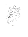
[034] A FIG. 8 inclui uma representação gráfica generalizada de energia específica de moagem versus o material cumulativo removido para ilustrar a mudança de meia-vida de energia de moagem específica.[034] FIG. 8 includes a generalized graphical representation of specific grinding energy versus cumulative material removed to illustrate the specific grinding energy half-life change.
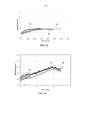
[035] A FIG. 9 inclui uma parcela de energia de moagem específica versus material cumulativo removido para artigos abrasivos convencionais e artigos abrasivos representativos de modalidades neste documento.[035] FIG. 9 includes a plot of specific grinding energy versus cumulative material removed for conventional abrasive articles and abrasive articles representative of embodiments herein.
[036] A FIG. 10 inclui uma parcela de energia de moagem específica versus material cumulativo removido para artigos abrasivos convencionais e artigos abrasivos representativos de modalidades neste documento.[036] FIG. 10 includes a plot of specific grinding energy versus cumulative material removed for conventional abrasive articles and abrasive articles representative of embodiments herein.
[037] A FIG. 11 inclui uma parte de um sistema para formar um material particulado de acordo com uma modalidade.[037] FIG. 11 includes a part of a system for forming a particulate material according to one embodiment.
[038] A FIG. 12 inclui uma parcela de energia de moagem específica versus material cumulativo removido para certos artigos abrasivos convencionais e artigos abrasivos representativos de modalidades neste documento.[038] FIG. 12 includes a plot of specific grinding energy versus cumulative material removed for certain conventional abrasive articles and abrasive articles representative of embodiments herein.
[039] A FIG. 13 inclui uma parcela de energia de moagem específica versus material cumulativo removido para artigos abrasivos representativos de modalidades neste documento.[039] FIG. 13 includes a plot of specific grinding energy versus cumulative material removed for abrasive articles representative of embodiments herein.
[040] A FIG. 14 inclui imagens representativas de porções de um material abrasivo revestido de acordo com uma modalidade usada para analisar a orientação de partículas abrasivas moldadas no apoio.[040] FIG. 14 includes representative images of portions of an abrasive material coated according to an embodiment used to analyze the orientation of abrasive particles molded onto the backing.
[041] O que segue é direcionado a métodos de formar partículas abrasivas moldadas e características de tais partículas abrasivas moldadas. As partículas abrasivas moldadas podem ser usadas em vários artigos abrasivos, incluindo, por exemplo, artigos abrasivos ligados, artigos abrasivos revestidos, e similares.[041] The following is directed at methods of forming molded abrasive particles and characteristics of such molded abrasive particles. The molded abrasive particles can be used in various abrasive articles, including, for example, bonded abrasive articles, coated abrasive articles, and the like.
[042] A FIG. 1A inclui uma ilustração de um sistema 150 para formar uma partícula abrasiva moldada de acordo com uma modalidade. O processo de formação de partículas abrasivas moldadas pode ser iniciado pela formação de uma mistura 101, incluindo um material cerâmico e um líquido. Em particular, a mistura 101 pode ser um gel formado por um material cerâmico em pó em um líquido, em que o gel pode ser caracterizado como um material estável em termos de forma, tendo a habilidade de substancialmente segurar um dado formato mesmo em seu estado (i.e., não disparado) verde. De acordo com uma modalidade, o gel pode ser formado por um material em pó de cerâmico como uma rede integrada de partículas discretas.[042] FIG. 1A includes an illustration of a
[043] A mistura pode conter um certo conteúdo de material sólido, material líquido, e aditivos, de tal forma que é adequado ter características reológicas para uso com o processo detalhado neste documento. Ou seja, em certas instâncias, a mistura pode ter uma certa viscosidade, e mais particularmente, características reológicas adequadas que forma uma fase dimensionalmente estável do material que pode ser formado através do processo, como notado neste documento. Uma fase dimensionalmente estável do material é um material que pode ser formado para ter um formato particular e substancialmente manter o formato tal que o formato é presente no objeto final formado.[043] The mixture may contain a certain content of solid material, liquid material, and additives, such that it is suitable to have rheological characteristics for use with the process detailed in this document. That is, in certain instances, the mixture may have a certain viscosity, and more particularly, adequate rheological characteristics that form a dimensionally stable phase of the material that can be formed through the process, as noted herein. A dimensionally stable phase of material is a material that can be formed to have a particular shape and substantially retain the shape such that the shape is present in the final formed object.
[044] A mistura 101 pode ser formada para ter um conteúdo específico de materiais sólidos, tais como o material do pó cerâmico. Por exemplo, em uma modalidade, a mistura 101 pode ser um conteúdo de sólidos de pelo menos 25% em peso, como por exemplo 35% em peso, ou até mesmo pelo menos 38% em peso para o peso total da mistura 101. Ainda, em pelo menos uma modalidade não-limitante, o conteúdo de sólidos da mistura 101 pode ser não maior que cerca de 75% em peso, como não maior que cerca de 70%, não maior que cerca de 65% em peso, não maior que cerca de 55% em peso, não maior que cerda de 45% em peso, e não maior que cerda de 42% em peso. Será contemplado que o conteúdo dos materiais de sólidos na mistura 101 pode ser dentro de uma faixa entre qualquer uma das porcentagens mínimas e máximas mencionadas acima.[044] The
[045] De acordo com uma modalidade, o material de pó cerâmico pode ser um óxido, uma nitrila, um carboneto, um boreto, um oxicarboneto, um oxinitreto, e uma combinação dos mesmos. Em casos particulares, o material cerâmico pode incluir alumina. Mas especificamente, o material cerâmico pode incluir material boemita, que pode ser um precursor de alfa alumina. O termo "boemita" geralmente é usado neste documento para denotar hidratos de alumina, incluindo mineral boemita, tipicamente sendo Al2O^H2O e com um teor de água da ordem de 15%, bem como pseudoboemita, com um teor de água superior a 15%, como 20-38% por peso. Note-se que boemita (incluindo pseudoboemita) tem uma estrutura cristalina específica e identificável e o padrão de difração de raios-x acordo exclusivo e como tal, é distinta de outros materiais aluminosos incluindo outras aluminas hidratadas como ATH (trihidróxido de alumínio) de um material precursor comum usado neste documento para a fabricação de materiais de partículas de boemita.[045] According to one embodiment, the ceramic powder material can be an oxide, a nitrile, a carbide, a boride, an oxycarbon, an oxynitride, and a combination thereof. In particular cases, the ceramic material may include alumina. More specifically, the ceramic material can include boehmite material, which can be an alpha alumina precursor. The term "boehmite" is generally used in this document to denote alumina hydrates, including the mineral boehmite, typically being Al2O^H2O and having a water content on the order of 15%, as well as pseudoboehmite, having a water content greater than 15% , such as 20-38% by weight. Note that boehmite (including pseudoboehmite) has a specific and identifiable crystal structure and unique x-ray diffraction pattern and as such is distinct from other aluminous materials including other hydrated aluminas such as ATH (aluminum trihydroxide) of a Common precursor material used herein for manufacturing boehmite particulate materials.
[046] Além disso, a mistura 101 pode ser formada para ter um conteúdo particular de material líquido. Alguns líquidos adequados podem incluir água. De acordo com uma modalidade, a mistura 101 pode ser formada para ter um conteúdo líquido menor que o conteúdo sólido da mistura 101. Em instâncias mais particulares, a mistura 101 pode ter um conteúdo líquido de pelo menos 25% em peso para o peso total de uma mistura 101. Em outras instâncias, a quantidade de líquido dentro da mistura 101 pode ser maior, como pelo menos 35% em peso, pelo menos 45% em peso, pelo menos 50% em peso, e até mesmo pelo menos 58% em peso. Ainda, em pelo menos uma modalidade não-limitante, o conteúdo líquido da mistura pode ser não maior que cerca de 75% em peso, não maior que cerca de 70%, não maior que cerca de 65% em peso, não maior que cerca de 62% em peso, e até mesmo não maior que cerca de 60% em peso. Será contemplado que o conteúdo do líquido na mistura 101 pode ser dentro de uma faixa entre qualquer uma das porcentagens mínimas e máximas mencionadas acima.[046] In addition, the
[047] Além disso, para facilitar o processamento e formação das partículas abrasivas moldadas de acordo com as modalidades neste documento, a mistura 101 pode ter um módulo de armazenamento particular. Por exemplo, a mistura 101 pode ter um módulo de armazenamento de pelo menos cerca de 1x10⁴ Pa, como pelo menos cerca de 4x10⁴ Pa, ou pelo menos cerca de 5x10⁴ Pa. No entanto, em pelo menos uma modalidade não limitante, a mistura 101 pode ter um módulo de armazenamento não maior que cerca de 1x10⁷ Pa, como não maior que cerca de 2x10⁶ Pa. Será contemplado que o módulo de armazenamento da mistura 101 pode ser dentro de uma faixa entre qualquer um dos valores mínimos e máximos mencionadas acima.[047] In addition, to facilitate the processing and formation of abrasive particles molded according to the embodiments in this document, the
[048] O módulo de armazenamento pode ser medido através de um sistema de placa paralelo usando os reômetros rotacionais ARES ou AR- G2, com um sistema de controle de temperatura de placa de Peltier. Para o teste, a mistura 101 pode ser extrudada dentro de um vão entre as duas placas que estão separadas por aproximadamente 8 mm. Após extrudar o gel no vão, a distância entre as duas placas, que defini o vão, é reduzida para 2 mm, até que a mistura 101 preenche totalmente o vão entre as placas. Depois de limpar o excesso de mistura, o vão é diminuído em 0,1 mm e o teste é iniciado. O teste é um teste de varredura de cepa por oscilação conduzido com configurações de instrumento um intervalo de cepa entre 01% a 100% a 6,28 rad/s (1 Hz) usando uma placa paralela de 25-mm e gravando 10 pontos por década. Dentro de 1 hora depois de completar o dentro, abaixe o vão novamente em 0,1 mm e repita o teste. O teste pode ser repetido até 6 vezes. O primeiro teste pode diferir do segundo e terceiro teste. Apenas os resultados do segundo e terceiro testes para cada espécime devem ser reportados.[048] The storage module can be measured through a parallel plate system using the ARES or AR-G2 rotational rheometers, with a Peltier plate temperature control system. For testing,
[049] Além disso, para facilitar o processamento e formação das partículas abrasivas moldadas de acordo com as modalidades neste documento, a mistura 101 pode ter uma viscosidade particular. Por exemplo, a mistura 101 pode ter uma viscosidade de pelo menos cerca de 4x10³ Pa s, pelo menos cerca de 5x10³ Pa s, pelo menos cerca de 6x10³ Pa s, pelo menos cerca de 8x 10³ Pa s, pelo menos cerca de 10x103 Pa s, pelo menos cerca de 20x103 Pa s, pelo menos cerca de 30x103 Pa s, pelo menos cerca de 40x103 Pa s, pelo menos cerca de 50x103 Pa s, pelo menos cerca de 60x103 Pa s, pelo menos cerca de 65x103 Pa s. Em pelo menos uma modalidade não limitante, a mistura 101 pode ter uma viscosidade não maior que cerca de 100x103 Pa s, não maior que cerca de 95x103Pas, não maior que cerca de 90x103 Pa s, ou até não maior do que cerca de 85x103 Pa s. Será contemplado que a viscosidade da mistura 101 pode ser dentro de uma faixa entre qualquer um dos valores mínimos e máximos mencionadas acima. A viscosidade pode ser medida da mesma maneira do que o módulo de armazenamento, como descrito acima.[049] In addition, to facilitate the processing and formation of abrasive particles molded in accordance with the embodiments herein, the
[050] Além disso, a mistura 101 pode ser formada para ter um conteúdo particular de materiais orgânicos, incluindo, por exemplo, aditivos orgânicos que podem ser distintos do líquido, para facilitar a formação e processamento as partículas abrasivas moldadas de acordo com as modalidades neste documento. Alguns aditivos orgânicos adequados pode incluir estabilizadores, ligantes, tais como frutose, sacarose, lactose, glicose, resinas curáveis UV, e similares.[050] In addition, the
[051] Notavelmente, as modalidades neste documento pode utilizar uma mistura 101 que pode ser distinta das pastas fluídas usadas nas operações de formação convencionais. Por exemplo, o conteúdo dos materiais orgânicos, dentro da mistura 101, particularmente, qualquer um dos aditivos orgânicos notados acima, pode ser uma quantidade menor em comparação com outros componentes dentro da mistura 101. Em pelo menos uma modalidade, a mistura 101 pode ser formada para ter não mais do que cerca de 30% em peso de material orgânico para o peso total da mistura 101. Em outras instâncias, a quantidade de materiais orgânicos pode ser menos, como não maior que cerca de 15% em peso, não maior que cerca de 10% me peso, ou até não maior que cerca de 5% em peso Ainda, em pelo menos uma modalidade não limitante, a quantidade de material orgânico dentro da mistura 101 pode ser de pelo menos cerca de 0,01% em peso, como pelo menos cerca de 0,5% em peso para um peso total da mistura 101. Será contemplado que a quantidade de materiais orgânicos na mistura 101 pode ser dentro de uma faixa entre qualquer um dos valores mínimos ou máximos notados acima.[051] Notably, the embodiments herein may utilize a
[052] Além disso, a mistura 101 pode ser formada para ter um conteúdo particular de ácidos ou bases distintas do líquido, para facilitar a formação e processamento as partículas abrasivas moldadas de acordo com as modalidades neste documento. Alguns ácidos ou bases adequados podem incluir ácido nítrico, ácido sulfúrico, ácido cítrico, ácido clórico, ácido tartárico, ácido fosfórico, nitrato de amônio, citrato de amônio. De acordo com uma modalidade particular, a mistura 101 pode ter um pH de menos de cerca de 5, e mais particularmente, dentro de uma faixa entre cerca de 2 e cerca de 4, usando um aditivo de ácido nítrico.[052] In addition, the
[053] O sistema 150 da FIG. 1A, pode incluir um molde 103. Conforme ilustrado, a mistura 101 pode ser fornecida dentro do interior de um molde 103 e ser configurada para ser extrudada através de uma abertura de molde 105 posicionada em uma extremidade do molde 103. Como ilustrado adicionalmente, a extrusão pode incluir a aplicação de uma força 180 (ou uma pressão) na mistura 101 para facilitar a extrusão da mistura 101 pela abertura de molde 105. O sistema 150 pode geralmente ser referido como um processo de impressão de tela. Durante a extrusão dentro da zona de aplicação 183, a tela 151 pode estar em contato direto com uma porção do correia 109. O processo de impressão de tela pode incluir extrudar a mistura 101 do molde 103 através de uma abertura de molde 105 na direção 191. Em particular, o processo de impressão de tela pode utilizar uma tela 151 de tal forma que a ao extrudar a mistura 101 pela abertura de tela 105, a mistura 101 pode ser forçada em uma abertura 152 na tela 151.[053] The
[054] De acordo com uma modalidade, uma pressão particular pode ser utilizada durante a extrusão. Por exemplo, a pressão pode ser de pelo menos 10 kPa, como pelo menos 500 kPa. Ainda, em pelo menos uma modalidade não limitante, a pressão utilizada durante a extrusão não pode ser maior do que 4 MPa. Será contemplado que a pressão usada para extrudar a mistura 101 pode ser dentro de uma faixa entre qualquer um dos valores mínimos e máximos mencionadas acima. Em instâncias particulares, a consistência da pressão entregue ao pistão 199 pode facilitar o processamento melhorado e a formação de partículas abrasivas moldadas. Notavelmente, uma entrega controlada de pressão consistente ao longo da mistura 101 e ao longo da largura do molde 103 pode facilitar o controle do processamento melhorado e características dimensionais melhoradas das partículas abrasivas melhoradas.[054] According to one embodiment, a particular pressure can be used during extrusion. For example, the pressure can be at least 10 kPa, such as at least 500 kPa. Furthermore, in at least one non-limiting embodiment, the pressure used during extrusion cannot be greater than 4 MPa. It will be contemplated that the pressure used to extrude the
[055] Referindo-se brevemente à FIG. 1B, uma parte de uma tela 151 é ilustrada. Como mostrado, a tela 151 pode incluir uma abertura 152, e mais particularmente, uma pluralidade de aberturas 152 que se estendem por um volume de uma tela 151. De acordo com uma modalidade, as aberturas 152 podem ter um formato de duas dimensões, como visto em um plano definido pelo comprimento (l) e largura (w) de uma tela que inclui vários formatos, por exemplo, polígonos, elipsoides, numerais, letras do alfabeto grego, letras do alfabeto latino, caracteres do alfabeto russo, formatos complexos incluindo uma combinação de formatos poligonais, e uma combinação dos mesmos. Em casos particulares, as aberturas 152 podem ter formatos poligonais de duas dimensões, tal como um triângulo, um retângulo, um quadrilátero, um pentágono, um hexágono, um heptágono, um octógono, um nonágono, um decágono, e uma combinação dos mesmos.[055] Referring briefly to FIG. 1B, a portion of a
[056] Como ilustrado ainda, a tela 151 pode ter aberturas 152 que são orientadas de uma maneira particular em relação umas às outras. Conforme ilustrado e de acordo com uma modalidade, cada uma das aberturas 152 pode ter substancialmente a mesma orientação em relação umas com as outras, e substancialmente a mesma orientação em relação a superfície da tela. Por exemplo, cada uma das aberturas 152 pode ter uma primeira borda 154 definindo um primeiro plano 155 para uma primeira fileira 156 das aberturas 152 estendendo-se lateralmente ao longo do eixo lateral 158 da tela 151. O primeiro plano 155 pode estender-se em uma direção substancialmente ortogonal para um eixo longitudinal 157 da tela 151.[056] As further illustrated, the
[057] Além disso, a primeira fileira 156 das aberturas 152 pode ser orientada em relação a uma direção de tradução para facilitar o processamento de partícula e formação controlada das partículas abrasivas moldadas. Por exemplo, as aberturas 152 podem ser arranjadas na tela 151 de tal forma que o primeiro plano 155 da primeira fileira 156 defina um ângulo relativo a direção de tradução 171. Conforme ilustrado, o primeiro plano 155 pode definir um ângulo que é substancialmente ortogonal em à direção de tradução 171. Ainda será contemplado em uma modalidade que a primeira fileira 156 pode ser definida por um primeiro plano 155 que defini um ângulo diferente no que diz respeito à direção de tradução, incluindo, por exemplo, um ângulo agudo ou um ângulo obtuso. Ainda será contemplado que as aberturas 152 pode não ser necessariamente arranjadas em fileiras. As aberturas 152 podem ser arranjadas em uma distribuição ordenada particular com relação umas às outras na tela 151, como na forma de um padrão de duas dimensões. Alternativamente, as aberturas podem ser dispostas em uma maneira aleatória na tela 151.[057] Furthermore, the
[058] A FIG. 1C inclui uma ilustração de uma parte da tela da FIG. 1B em um ponto de liberação, de acordo com uma modalidade. Conforme ilustrado, a tela 151 pode incluir aberturas 152 que tenham uma orientação particular no que diz respeito ao ponto de liberação 160, em que a tela 151 é separada de uma correia 109. A orientação controlada das aberturas 152 com relação a direção de tradução 171 no ponto de liberação 160 pode facilitar o controle de características particulares das partículas abrasivas moldadas. Por exemplo, de acordo com a modalidade ilustrada na FIG. 1C, a separação da tela 151 e a correia 109 pode ser iniciado na primeira borda 154 da primeira fileira 154 das aberturas 152 e ser completado em um ponto 159 de cada uma das aberturas 152, oposta a primeira borda 154.[058] FIG. 1C includes an illustration of a portion of the fabric of FIG. 1B at a release point, according to an embodiment. As illustrated, the
[059] Tal orientação pode facilitar a formação de partículas abrasivas moldadas com certas características. A FIG. 2A inclui uma vista lateral de uma partícula abrasiva moldada formada de acordo com uma modalidade. Notavelmente, a partícula abrasiva moldada 200 é representativa de uma partícula formada de uma orientação de abertura como ilustrado na FIG. 1B. De acordo com uma modalidade, a partícula 200 pode ter uma primeira altura (h1) e um primeiro canto 254 formado de um primeiro canto 174 correspondente de uma abertura 152 que é maior do que uma segunda altura (h2) de uma partícula em um segundo canto 259 formado a partir e correspondente a um canto 159 de uma abertura 152.[059] Such an orientation can facilitate the formation of molded abrasive particles with certain characteristics. FIG. 2A includes a side view of a shaped abrasive particle formed in accordance with one embodiment. Notably, the molded
[060] Será apreciado que outras orientações das aberturas 152 da tela, relativas a direção de tradução 171, o eixo lateral 158, o eixo longitudinal 157 pode ser utilizado, que pode facilitar a formação de características distintas de partículas abrasivas. Por exemplo, a FIG. 1D inclui uma visão de cima para baixo de uma parte de uma tela de acordo com uma modalidade. Conforme ilustrado, as aberturas 152 podem ser orientadas em uma direção oposta em relação a direção de tradução 171, como as aberturas ilustradas na FIG. 1B. Notavelmente, as aberturas 152 podem ser orientadas de tal forma que em um ponto de liberação, a separação da tela 151 de uma correia 109 pode ser iniciada nos pontos 159 das aberturas 152, em oposição aos cantos 154.[060] It will be appreciated that other orientations of the
[061] A FIG. 2B inclui uma vista lateral de uma partícula abrasiva moldada formada de acordo com uma modalidade. Notavelmente, a partícula abrasiva moldada 210 é representativa de uma partícula formada de uma orientação de abertura como ilustrado na FIG. 1D. De acordo com uma modalidade, a partícula 210 pode ter uma primeira altura (h1) e um primeiro canto 259 formado e correspondendo a um primeiro canto 159 de uma abertura 152 que é maior que uma segunda altura (h2) de uma partícula em um segundo canto 254 formado a partir de e correspondente a um canto 174 de uma abertura 152.[061] FIG. 2B includes a side view of a shaped abrasive particle formed in accordance with one embodiment. Notably, the molded
[062] A FIG. 1E inclui uma visão de cima para baixo de uma parte de uma tela de acordo com outra modalidade. Conforme ilustrado, as aberturas 152 podem ter uma orientação mista tal que cada uma das aberturas 152 dentro da fileira 156 podem ter uma orientação alternada. Por exemplo, uma primeira parte 186 da abertura 152 da fileira 156 pode ter uma primeira orientação em relação ao eixo lateral 158, o eixo longitudinal 157 e/ou a direção de tradução 171. Além disso, conforme ilustrado, uma segunda parte 187 da abertura 152 da fileira 156 pode ter uma segunda orientação diferente da primeira orientação, em relação ao eixo lateral 158, o eixo longitudinal 157, e/ou a direção de tradução 171.[062] FIG. 1E includes a top-down view of a portion of a screen according to another embodiment. As illustrated, the
[063] Ainda, será contemplado que as aberturas 152 podem ter outras orientações em relação umas às outras e em relação ao eixo lateral 158, o eixo longitudinal 157, e/ou a direção de tradução 171. A FIG. 1F inclui uma visão de cima para baixo de uma parte de uma tela de acordo com outra modalidade. Conforme ilustrado, as aberturas 152 podem ter uma orientação mista, de tal forma que cada uma das aberturas 152 dentro da fileira 156 pode ter uma orientação diferente em relação à pelo menos uma abertura dentro da fileira 156, e mais particularmente, uma orientação diferente em relação a combinação de aberturas dentro da fileira 156. A orientação controlada das aberturas relativas ao eixo lateral 158, o eixo longitudinal 157, e/ou a direção de tradução 171 pode facilitar a formação de um lote de partículas abrasivas moldadas tendo várias características predeterminadas descritas nas modalidades neste documento.[063] Further, it will be contemplated that the
[064] Referindo-se novamente a FIG. 1A, depois de forçar a mistura 101 através da abertura de molde 105 e uma parte da mistura 101 através das aberturas 152 na tela 151, partículas abrasivas moldadas precursoras 123 podem ser impressas em uma correia 109 disposta embaixo de uma tela 151. De acordo com uma modalidade particular, partículas abrasivas moldadas precursoras 123 pode ter um formato substancialmente replicando o formato das aberturas 152. Notavelmente, a mistura 101 pode ser forçada através da tela em uma maneira rápida, tal que o tempo de residência médio da mistura 101 com as aberturas 152 pode ser menos que cerca de 2 minutos, menos que cerca de 1 minuto, menos que cerca de 40 segundos, ou até menos que cerca de 20 segundos. Em modalidades não limitantes particulares, a mistura 101 pode ser substancialmente não alterada durante a impressão na medida em que atravessa as aberturas de tela 152, assim não sofrendo nenhuma alteração na quantidade de componentes da mistura original, e pode sofrer nenhuma secagem apreciável nas aberturas 152 da tela 151.[064] Referring again to FIG. 1A, after forcing the
[065] Adicionalmente, o sistema 151 pode incluir uma etapa de fundo 198 dentro da zona de aplicação 183. Durante o processo de formação de partículas abrasivas moldadas, a correia 109 pode viajar sobre a etapa inferior 198, que pode oferecer um substrato adequado para a formação. Além disso, a etapa inferior 198 pode ter uma superfície superior em contato direto com a correia 109 tendo uma geometria particular e/ou dimensões (e.g., achatamento, rugosidade de superfície, etc.), que pode facilitar o controle melhorado das características dimensionais de partículas abrasivas moldadas.[065] Additionally, the
[066] Durante a operação do sistema 150, a tela 151 pode ser traduzida na direção 153, enquanto a correia 109 pode ser traduzida em uma direção 110, substancialmente similar a direção 153, pelo menos dentro da zona de aplicação 183, para facilitar a operação de impressão contínua. Sendo assim, as partículas abrasivas percursoras 153 podem ser impressas em uma correia 109 e traduzidas ao longo da correia para se submeter-se a um processamento posterior. Será contemplado que um processamento adicional pode incluir processos descritos nas modalidades neste documento, incluindo, por exemplo, moldagem, aplicação de outros materiais (e.g., material dopante), secagem, e similares.[066] During the operation of the
[067] Em algumas modalidades, a correia 109 e/ou tela 151 podem ser traduzidas enquanto a mistura 101 é extrudada através da abertura de molde 105. Conforme ilustrado no sistema 100, a mistura 101 pode ser extrudada em uma direção 191. A direção da tradução 110 de um cinto 109 e/ou tela 151 pode ser angulada em relação a direção de extrusão 191 da mistura. Enquanto o ângulo entre a direção da tradução 110 e a direção de extrusão 191 é ilustrado como sendo substancialmente ortogonal em um sistema 100, outros ângulos são contemplados, incluindo, por exemplo, um ângulo agudo ou um ângulo obtuso. Além disso, enquanto a mistura 101 é ilustrada enquanto sendo extrudada em uma direção 191, que é angulada em relação a direção de tradução 110 de uma correia 109 e/ou da tela 151, em uma modalidade alternativa, a correia 109 e/ou a tela 151, e a mistura 101 pode ser extrudada substancialmente na mesma direção.[067] In some embodiments, the
[068] A correia 109 e/ou a tela 151 pode ser traduzida em uma taxa particular para facilitar o processamento. Por exemplo, a correia 109 e/ou a tela 151 pode ser traduzida em uma taxa de pelo menos 3 cm/s. Em outras modalidades, a taxa de tradução da correia 109 e/ou da tela 151 pode ser maior, como pelo menos cerca de 4 cm/s, pelo menos cerca de 6 cm/s, pelo menos cerca de 8 cm/s, ou até pelo menos cerca de 10 cm/s Ainda, em pelo menos uma modalidade não limitante, a correia 109 pode ser traduzida em uma direção 110 em uma taxa não maior que cerca de 5 m/s, não maior que cerca de 1 m/s, ou até não maior que cerca de 0,5 m/s. Será contemplado que uma correia 109 e/ou a tela 151 pode ser traduzida a uma taxa dentro de uma faixa entre qualquer um dos valores mínimos ou máximos notados acima, e ainda, pode ser traduzida a uma taxa substancialmente igual em relação umas às outras.[068] The
[069] Para certos processos de acordo com modalidades neste documento, a taxa de tradução da correia 109, quando comparado a taxa de extrusão da mistura 101 na direção 191 pode ser controlada para facilitar o processamento adequado.[069] For certain processes according to embodiments in this document, the translation rate of the
[070] Após a mistura 101 ser extrudada pela abertura de molde 105, a mistura 101 pode ser traduzida ao longo da correia 109 embaixo do fio da navalha 107 fixada em uma superfície do molde 103. O fio da navalha 107 pode definir a região na frente do molde 103, o que facilita o deslocamento da mistura 101 nas aberturas 152 da tela 151.[070] After the
[071] Certos parâmetros de processamento podem ser controlados para facilitar características da partícula abrasiva moldada precursora 123 e a partículas abrasivas moldadas finalmente formadas descritas neste documento. Alguns parâmetros de processos exemplares pode incluir a distância de liberação 197, uma viscosidade da mistura, um módulo de armazenamento da mistura, propriedades mecânicas do estágio inferior, características geométricas e dimensionais do estágio inferior, uma espessura da tela, uma rigidez da tela, um conteúdo sólida da mistura, um conteúdo carregador da mistura, um ângulo de liberação, uma velocidade de tradução, uma temperatura, o conteúdo do agente de liberação, a pressão exercida na mistura, uma velocidade de correia, e uma combinação dos mesmos.[071] Certain processing parameters can be controlled to facilitate characteristics of the precursor molded
[072] De acordo com uma modalidade, um parâmetro de processo particular pode incluir controlar a distância de liberação 197 entre uma posição de preenchimento e uma posição de liberação. Em particular, a distância de liberação 197 pode ser uma distância medida em uma direção da direção de tradução da correia entre a extremidade do molde 103 e o ponto inicial de separação entre a tela 151 e a correia 109. De acordo com a modalidade, controlar a distância de liberação 197 pode afetar pelo menos uma característica dimensional das partículas abrasivas moldadas precursoras 123 ou as partículas abrasivas moldadas finalmente formadas. Além disso, o controle da distância de liberação 197 pode afetar a combinação das características dimensionais. Características dimensionais exemplares incluem comprimento, largura, altura interior (hi), variação de altura interior (Vhi), diferencia de altura, razão de perfil, índice de flashing, índice de abaulamento (dishing), ângulo de inclinação, e uma combinação dos mesmos.[072] According to an embodiment, a particular process parameter may include controlling the
[073] De acordo com uma modalidade, a distância de liberação 197 pode ser não maior que o comprimento da tela 151. Em outras instâncias, a distância de liberação 197 pode ser não maior que a largura da tela 151. Ainda, em uma modalidade particular, a distância de liberação 197 pode ser não maior que 10 vezes a maior dimensão de uma abertura 152 em uma tela 151. Por exemplo, as aberturas 152 pode ter um formato triangular, tal como ilustrado na FIG. 1B, e a distância de liberação 197 pode ser não maior que 10 vezes o comprimento de um lado da abertura 152, definido o formato triangular. Em outras instâncias, a distância de liberação 197 pode ser menos, como não maior que 8 vezes a maior dimensão da abertura 152 na tela 151, como não maior que cerca de 5 vezes, não maior que cerca de 3 vezes, não maior que cerca de 2 vezes, ou até não maior que a maior dimensão da abertura 152 na tela 151.[073] According to an embodiment, the
[074] Em instâncias mais particulares, a distância de liberação 197 pode ser não maior que cerca de 30 mm, como não maior que cerca de 20 mm, ou até não maior que cerca de 10 mm. Pelo menos uma modalidade, a distância de liberação pode ser substancialmente zero ou, mais particularmente, pode ser essencialmente zero. Nesse sentido, a mistura 101 pode ser disposta em uma das aberturas dentro da zona de aplicação 183 e a tela 151 e a correia 109 podem ser separadas uma da outra na extremidade da moldura 103 ou mesmo antes da extremidade do molde 103.[074] In more particular instances, the
[075] De acordo com um método particular de formação, a distância de liberação 197 pode ser essencialmente zero, que pode facilitar substancialmente o preenchimento simultâneo das aberturas 152 com a mistura 101 e a separação entre a correia 109 e a tela 151. Por exemplo, antes que a tela 151 e cinto 109 passam o final de 103 morrer e sair da zona de aplicação 183, separação da tela 151 e cinto 109 pode ser iniciada. Em modalidades mais particulares, a separação entre a tela 151 e a correia 109 pode ser iniciada imediatamente após as aberturas 152 serem preenchidas com a mistura 101, antes de deixar a zona de aplicação 183 e enquanto a tela 151 é localizada sob o molde. Em ainda outra modalidade, a separação entre a tela 151 e a coreia 109 pode ser iniciada enquanto a mistura 101 é posicionada dento da abertura 152 da tela 151. Em uma modalidade alternativa, a separação entre a tela 151 e a correia 109 pode ser iniciada antes da mistura 101 ser posicionada nas aberturas 152 da tela 151. Por exemplo, antes das aberturas 152 passarem sob a abertura de molde 105, a correia 109 e tela 151 estão sendo separadas, de tal forma que um vão existe entre a correia 109 e a tela 151, enquanto a mistura está sendo forçada pelas aberturas 152. Ver, por exemplo, a FIG. 11, demonstrando a operação de impressão, em que a distância de liberação 197 é substancialmente zero e a separação entre a correia 109 e a tela 151 é iniciada antes de passar soba a abertura de molde 105. Além disso, será contemplado que a separação da correia 109 e da tela 151 pode ocorrer antes de entrar na zona de aplicação 183 (definida pela frente do molde 103), tal que a distância de liberação pode ser de um valor negativo.[075] According to a particular method of formation, the
[076] O controle de distância de liberação 197 pode facilitar a formação controlada das partículas abrasivas moldadas, tendo características dimensionais melhoradas e tolerâncias dimensionais melhoradas (e.g., baixa variabilidade característica dimensional). Por exemplo, diminuir a distância de liberação 197 em combinação com outros parâmetros de processamento controlados pode facilitar a formação melhorada das partículas abrasivas moldadas, tendo valores de altura interior maiores (hi).[076] The
[077] Adicionalmente, como ilustrado na FIG. 11, um controle de altura de separação 196 entre uma superfície da correia 109 e a superfície inferior 198 da tela 151 pode facilitar a formação controlada de partículas abrasivas moldadas, tendo características dimensionais melhoradas e tolerâncias dimensionais melhoradas (e.g., baixa variabilidade característica dimensional). A altura de separação 196 pode ser relacionada a espessura da tela 151, a distância entre a correia 109 e o molde 103, e uma combinação dos mesmos. Além disso, uma ou mais características dimensionais (e.g., altura interior) da partícula abrasiva moldada precursora 123 pode ser controlada pelo controle da altura de separação 196 e a da espessura de tela 151. A FIG. 11 demonstra a operação de impressão em que a distância de liberação 197 é substancialmente zero e a separação entre a correia 109 e a tela 151 é iniciada antes da correia 109 e da tela 151 passarem sob a abertura de molde 105. Mais particularmente, a liberação entre a correia 109 e a tela 151 é iniciada na medida em que a correia 109 e a tela 151 entram na zona de aplicação 183, e passam sob a frente do molde 103. Além disso, será contemplado que, em algumas modalidades, a separação da correia 109 e da tela 151 pode ocorrer antes da correia 109 e da tela 151 entrarem na zona de aplicação 183 (definida pela frente do molde 103), tal que a distância de liberação 197 pode ser de um valor negativo.[077] Additionally, as illustrated in FIG. 11, a
[078] Em instâncias particulares, a tela 151 pode ter uma espessura média não maior que cerca de 700 mícrons, como não maior que cerca de 690 mícrons, não maior que cerca de 680 mícrons, não maior que cerca de 670 mícrons, não maior que cerca de 650 mícrons, não maior que cerca de 640 mícrons. Ainda assim, a espessura média da tela pode ser de pelo menos cerca de 100 mícrons, como pelo menos cerca de 300 mícrons, ou até pelo menos cerca de 400 mícrons.[078] In particular instances, the
[079] Em uma modalidade, o processo de controle pode incluir um processo multietapa, que pode incluir medir, calcular, ajustar, e uma combinação dos mesmos. Tais processos podem ser aplicados ao parâmetro de processo, uma característica dimensional, uma combinação de características dimensionais, e uma combinação dos mesmos. Por exemplo, em uma modalidade, controlar pode incluir medir uma ou mais características dimensionais, calcular um ou mais valores com base no processo de medir a uma ou mais característica dimensional, e ajustar um ou mais parâmetros de processo (e.g., a distância de liberação 197) com base no um ou mais valor calculado.[079] In one embodiment, the control process may include a multi-step process, which may include measuring, calculating, adjusting, and a combination thereof. Such processes can be applied to the process parameter, a dimensional feature, a combination of dimensional features, and a combination thereof. For example, in one embodiment, controlling may include measuring one or more dimensional characteristics, calculating one or more values based on the process of measuring the one or more dimensional characteristics, and adjusting one or more process parameters (e.g., the release distance 197) based on the one or more calculated values.
[080] O processo de controle, e particularmente qualquer um dos processos de medição, cálculo, e ajuste pode ser completado antes, depois ou durante a operação do processo para formar a partícula abrasiva moldada. Em uma modalidade particular, o processo de controle pode ser um processo contínuo, em que uma ou mais características dimensionais são medidas e um ou mais parâmetros de processo são mudados (i.e., ajustados) em resposta as características dimensionais medidas. Por exemplo, o processo de controlar pode incluir medir uma característica dimensional como a diferença em altura de uma partícula abrasiva moldada precursora 123, calculando a diferença no valor de altura da partícula abrasiva moldada precursora 123, e mudando a distância de liberação 197 para mudar a diferença de valor de altura da partícula abrasiva moldada precursora 123.[080] The control process, and particularly any of the measurement, calculation, and adjustment processes can be completed before, after or during the operation of the process to form the molded abrasive particle. In a particular embodiment, the control process can be a continuous process, in which one or more dimensional characteristics are measured and one or more process parameters are changed (i.e., adjusted) in response to the measured dimensional characteristics. For example, the controlling process may include measuring a dimensional characteristic such as the difference in height of a precursor molded
[081] Referindo-se novamente a FIG. 1, depois de extrudar a mistura 101 nas aberturas 152 da tela 151, a correia 109 e a tela 151 pode ser traduzida para liberar a zona 185, em que a correia 109 e a tela 151 pode ser separada para facilitar a formação de partículas abrasivas moldadas precursoras 123. De acordo com uma modalidade, a tela 151 e a correia 109 podem ser separadas uma das outras dentro da zona de liberação 185 em ângulo de liberação particular.[081] Referring again to FIG. 1, after extruding the
[082] Na verdade, como ilustrado, as partículas abrasivas moldadas precursoras 123 podem ser traduzidas através de uma série de zonas em que vários processos de tratamento podem ser conduzidos. Alguns processos de tratamento exemplares adequados podem incluir secar, aquecer, curar, reagir, radiar, mexer, agitar, planar, calcinar, sinterizar, triturar, peneirar, dopar, e uma combinação dos mesmos. De acordo com uma modalidade, as partículas abrasivas moldadas precursoras 123 podem ser traduzidas através de uma zona de moldagem opcional 113, em que pelo menos uma superfície exterior das partículas pode ser moldada como descritas nas modalidades neste documento. Além disso, as partículas abrasivas moldadas precursoras 123 podem ser traduzidas através de uma zona de aplicação 131, em que um material dopante pode ser aplicado em pelo menos uma superfície exterior das partículas, como descrito nas modalidades neste documento. E ainda, as partículas precursoras abrasivas 123 podem ser traduzidas em uma correia 109 através uma zona de pós formação 125, em que uma variedade de processos, incluindo, por exemplo, a secagem, podem ser conduzidos nas partículas abrasiva moldada precursora 123, como descrito nas modalidades neste documento.[082] Indeed, as illustrated, the precursor molded
[083] A zona de aplicação 131 pode ser usada par aplicar o material em uma superfície exterior das partículas abrasivas moldadas precursoras 123. De acordo com uma modalidade, o material dopante pode ser aplicado ás partículas abrasivas moldadas precursoras 123. Mais particularmente, como ilustrando, na FIG. 1, a zona de aplicação 131 pode ser posicionada depois da zona de formação 125. Como tal, o processo de aplicar o material dopante pode ser completado nas partículas abrasivas moldadas precursoras 123. No entanto, será contemplado que a zona de aplicação 131 pode ser posicionada em outros lugares dentro do sistema 100. Por exemplo, o processo de aplicar um material dopante pode ser completado antes da formação das partículas abrasivas moldadas precursoras 123. Em ainda outras instâncias, que serão descritas em maiores detalhes neste documento, o processo de aplicar o material dopante pode ser conduzido simultaneamente com um processo de formação das partículas abrasivas moldadas precursoras 123.[083] The
[084] Dentro da zona de aplicação 131, o material dopante pode ser aplicado usando vários métodos, incluindo, por exemplo, pulverização, mergulhando, impregnando, transferindo, perfuração, corte, prensagem, esmagamento, ou qualquer combinação dos mesmos. Em instâncias particulares, a zona de aplicação 131 pode utilizar um bico de pulverização, ou uma combinação de bicos de pulverização 132 e 133 para pulverizar o material dopante nas partículas abrasivas moldadas precursoras 123.[084] Within the
[085] De acordo com uma modalidade, a aplicação do material dopante pode incluir a aplicação de um material particular, como um precursor. Em certas instâncias, o precursor por ser um sal que inclui um material dopante a ser incorporado nas partículas abrasivas moldadas finalmente formadas. Por exemplo, o sal do metal pode incluir um elemento ou composto que é o precursor do material dopante. Será contemplado que um material salino pode estar na forma líquida, como em um dispersor compreendo um sal e um carregador líquido. O sal pode incluir nitrogênio, e mais particularmente, podem incluir um nitrato. Em outras modalidades, o sal pode ser um cloreto, sulfato, fosfato, e uma combinação dos mesmos. Em uma modalidade, o sal pode incluir um metal nitrato, e mais particularmente, consistir essencialmente de um metal nitrato.[085] According to one embodiment, the application of the dopant material may include the application of a particular material, as a precursor. In certain instances, the precursor can be a salt that includes a dopant material to be incorporated into the finally formed shaped abrasive particles. For example, the metal salt can include an element or compound that is a precursor to the doping material. It will be appreciated that a salt material may be in liquid form, as in a disperser comprising a salt and a liquid carrier. The salt can include nitrogen, and more particularly, can include a nitrate. In other embodiments, the salt can be a chloride, sulfate, phosphate, and a combination thereof. In one embodiment, the salt can include a nitrate metal, and more particularly, consist essentially of a nitrate metal.
[086] Em uma modalidade, o material dopante pode incluir um elemento ou composto como um elemento alquil, elemento alcalino terroso, terras raras, háfnio, zircônio, nióbio, tântalo, molibdênio, vanádio, ou uma combinação dos mesmos. Em uma modalidade particular, o material dopante inclui um elemento ou composto, incluindo um elemento como lítio, sódio, potássio, magnésio, cálcio, estrôncio, bário, escândio, ítrio, lantânio, cério, praseodímio, nióbio, háfnio, zircônio, tântalo, molibdênio, vanádio, crômio, cobalto, ferro, germânio, manganês, níquel, titânio, zinco, e uma combinação dos mesmos.[086] In one embodiment, the doping material may include an element or compound such as an alkyl element, alkaline earth element, rare earth, hafnium, zirconium, niobium, tantalum, molybdenum, vanadium, or a combination thereof. In a particular embodiment, the dopant material includes an element or compound, including an element such as lithium, sodium, potassium, magnesium, calcium, strontium, barium, scandium, yttrium, lanthanum, cerium, praseodymium, niobium, hafnium, zirconium, tantalum, molybdenum, vanadium, chromium, cobalt, iron, germanium, manganese, nickel, titanium, zinc, and a combination thereof.
[087] Em instâncias particulares, o processo de aplicar um material dopante pode incluir selecionar a colocação do material dopante em uma superfície exterior de uma partícula abrasiva moldada precursora 123. Por exemplo, o processo de aplicar o material dopante pode incluir a aplicação do material dopante em uma superfície superior ou superfície de fundo de partículas abrasivas moldadas precursoras 123. Em ainda outra modalidade, uma ou mais superfícies laterais das partículas abrasivas moldadas precursoras 123 podem ser tratadas de tal forma que o material dopante é aplicado nas mesmas. Será contemplado que vários métodos podem ser usados para aplicar o material dopante a várias superfícies exteriores das partículas abrasivas moldadas precursoras 123. Por exemplo, o processo de pulverização pode ser usado para aplicar o material dopante em uma superfície superior ou superfície lateral de uma partícula abrasiva moldada precursora 123. Ainda, em uma modalidade alternativa, um material dopante pode ser aplicado na superfície de fundo das partículas abrasivas moldadas precursoras 123 através de um processo como o mergulho, depósito, impregnação, ou combinação dos mesmos. Será contemplado que a superfície da correia 109 pode ser tratada com o material dopante para facilitar a transferência do material dopante com o fundo da superfície das partículas abrasivas moldadas precursoras 123.[087] In particular instances, the process of applying a dopant material may include selecting placement of the dopant material on an exterior surface of a precursor molded
[088] Depois de formar as partículas abrasivas precursoras 123, as partículas podem ser traduzidas através de uma zona de pós formação 125. Vários processos podem ser conduzidos na zona de pós formação 125, incluindo tratar as partículas abrasivas moldadas precursoras 123. Em uma modalidade, a zona de pós formação 125 pode incluir um processo de aquecimento em que as partículas abrasivas moldadas precursoras 123 podem ser secas Secagem pode incluir a remoção de um conteúdo particular do material, incluindo voláteis, como água. De acordo com uma modalidade, o processo de secagem pode ser conduzido em uma temperatura de secagem não maior que cerca de 300°C, como não maior que cerca de 280°C, ou até não maior que cerca de 250°C. Ainda, em uma modalidade não limitante, o processo de secagem pode ser conduzido em uma temperatura de secagem de pelo menos 50°C. Será contemplado que a temperatura de secagem pode ser dentro de uma faixa entre qualquer uma das temperaturas mínimas ou máximas mencionadas acima. Além disso, as partículas abrasivas moldadas precursoras 123 podem ser traduzidas através de uma zona de pós formação em uma taxa particular, como pelo menos cerca de 0,2 pés/min e não maior que cerca de 8 pés/min.[088] After forming the precursor
[089] Além disso, o processo de secagem pode ser conduzido por uma duração particular. Por exemplo, o processo de secagem pode não ser maior que cerca de seis horas.[089] In addition, the drying process can be conducted for a particular duration. For example, the drying process may not take longer than about six hours.
[090] Depois que as partículas abrasivas moldadas precursoras 123 são traduzidas pela zona de pós formação 125, as partículas abrasivas moldadas precursoras 123 podem ser removidas da correia 109. As partículas abrasivas moldadas precursoras 123 podem ser coletadas em um bin 127 para processamento posterior.[090] After the precursor molded
[091] De acordo com uma modalidade, o processo de formação das partículas abrasivas moldadas pode ainda compreender um processo de sinterização. Para determinados processos de modalidades neste documento, a sinterização pode ser conduzida depois de coletar as partículas abrasivas moldadas precursoras 123 da correia 109. Alternativamente, a sinterização pode ser um processo que é conduzido enquanto as partículas abrasivas moldadas precursoras 123 estão na correia. A Sinterização das partículas abrasivas moldadas precursoras 123 pode ser utilizada para densificar as partículas, que estão geralmente em um estado verde. Em uma instância específica, o processo de sinterizar pode facilitar a formação de uma fase de alta temperatura de um material cerâmico. Por exemplo, em uma modalidade, as partículas abrasivas moldadas precursoras 123 podem ser sinterizadas de tal forma que a fase de alta temperatura da alumina, como alfa alumina, é formada. Em uma instância, uma partícula abrasiva moldada pode compreender pelo menos cerca de 90% em peso de alfa alumina para um peso total da partícula. Em outras instâncias, o conteúdo de alfa alumina pode ser maior, de tal forma que a partícula abrasiva moldada pode consistir essencialmente de alfa alumina.[091] According to one embodiment, the process of forming the molded abrasive particles may further comprise a sintering process. For certain processes of embodiments herein, sintering may be conducted after collecting the precursor molded
[092] Adicionalmente, o corpo das partículas abrasivas moldadas podem ter formatos de duas dimensões particulares. Por exemplo, o corpo pode ter um formato de duas dimensões, como visto em um plano definido pelo comprimento e largura, tendo um formato poligonal, um formato elipsoidal, um numeral, um caractere de alfabeto grego, um caractere de alfabeto latino, um caractere de alfabeto russo, formatos complexos utilizando uma combinação de formatos poligonais e combinações dos mesmos. Formas poligonais particulares incluindo triângulo, retângulo, quadrilátero, pentágono, hexágono, heptágono, octágono, nonágono, decágono, ou qualquer combinação dos mesmos.[092] Additionally, the body of the molded abrasive particles may have particular two-dimensional formats. For example, the body may have a two-dimensional shape, as seen in a plane defined by length and width, having a polygonal shape, an ellipsoidal shape, a numeral, a Greek alphabet character, a Latin alphabet character, a Russian alphabet, complex shapes using a combination of polygonal shapes and their combinations. Particular polygonal shapes including triangle, rectangle, quadrilateral, pentagon, hexagon, heptagon, octagon, nonagon, decagon, or any combination thereof.
[093] A FIG. 3A inclui uma ilustração de uma vista em perspectiva de uma partícula abrasiva de acordo com uma modalidade. Adicionalmente, a FIG. 3B inclui uma ilustração transversal de uma partícula abrasiva da FIG. 3A. O corpo 301 inclui uma superfície superior 303, uma superfície de fundo grande 304 oposta à superfície superior 303. A superfície superior 303 e a superfície de fundo 304 podem ser separadas uma da outra pelas superfícies laterais 305, 306, e 307. Conforme ilustrado, o corpo 301 da partícula abrasiva moldada 300 pode ter um formato geralmente triangular, como visto em um plano da superfície superior 303. Em particular, o corpo 301 pode ter um comprimento (Lmédio) como mostrado na FIG. 3B, que pode ser medido na superfície de fundo 304 do corpo 301 e estendendo-se do canto 313 através de um ponto médio 381 do corpo 301 para o ponto médio na extremidade oposta 314 do corpo. Alternativamente, o corpo pode ser definido por um segundo comprimento e um perfil de comprimento (Lp), que é a medida da dimensão do corpo de uma vista lateral da superfície superior 303 de um primeiro canto 313 para um canto adjacente 312. Notavelmente, a dimensão de Lmédio pode ser um comprimento que define a distância entre uma altura em um canto (hc) e uma altura em um ponto médio (hm) oposto ao canto. A dimensão Lp pode ter um comprimento de perfil ao longo da lateral da partícula (como visto de uma vista lateral, como mostrado nas FIGSs. 2A e 2B), definindo a distância entre h1 e h2. A referência neste documento para o comprimento pode ser referência para Lmédio ou Lp.[093] FIG. 3A includes an illustration of a perspective view of an abrasive particle according to one embodiment. Additionally, FIG. 3B includes a cross-sectional illustration of an abrasive particle of FIG. 3A.
[094] O corpo 301 pode ainda incluir uma largura (w) que é a dimensão mais longa do corpo e se estende ao longo de uma lateral. A partícula abrasiva moldada pode ainda incluir uma altura (h), que pode ser uma dimensão da partícula abrasiva moldada estendendo-se em uma direção perpendicular ao comprimento e a largura em uma direção definida pela superfície lateral do corpo 301. Nomeadamente, como será descrito em mais detalhes neste documento, o corpo 301 pode ser definido por várias alturas dependendo na localização do corpo. Em casos específicos, a lateral pode ser maior ou igual ao comprimento, o comprimento pode ser maior ou igual a altura, e a largura pode ser maior ou igual a altura.[094] The
[095] Além disso, a referência neste documento a qualquer característica dimensional (e.g., h1, h2, hi, w, Lmédio, Lp, e similares) e variação de uma característica dimensional pode ser uma referência a dimensão de uma única partícula de um lote, um valor mediano, ou um valor médio derivado da análise de uma amostragem de partículas adequada de pelo menos uma primeira parte de um lote. Ao menos que explicitamente declarado, a referência neste documento a uma característica dimensional pode ser considerada referência a um valor mediano que é baseado em um valor estatisticamente significante derivado de um tamanho de amostra de um número de partículas de um lote de partículas. Nomeadamente, para certas modalidades neste documento, o tamanho da amostra pode incluir pelo menos 40 partículas aleatoriamente selecionadas de um lote de partículas. Um lote de partículas pode ser um grupo de partículas que são coletadas de um único processo executado e, mais particularmente, pode incluir uma quantidade de partículas abrasivas moldadas adequadas para formar um produto abrasivo de grau comercial, como pelo menos 20 lbs. de partículas.[095] In addition, the reference in this document to any dimensional characteristic (e.g., h1, h2, hi, w, Lmean, Lp, and the like) and variation of a dimensional characteristic may be a reference to the size of a single particle of a lot, a median value, or an average value derived from the analysis of a suitable particulate sample from at least a first part of a lot. Unless explicitly stated, reference in this document to a dimensional characteristic may be considered to be a reference to a median value that is based on a statistically significant value derived from a sample size of a number of particles from a particle lot. Namely, for certain embodiments herein, the sample size may include at least 40 randomly selected particles from a particle batch. A particle batch can be a group of particles that are collected from a single process run, and more particularly can include an amount of molded abrasive particles suitable to form a commercial grade abrasive product, such as at least 20 lbs. of particles.
[096] De acordo com uma modalidade, o corpo 301 de uma partícula abrasiva moldada pode ter uma altura do primeiro canto (hc) em uma primeira região de um corpo definido por um canto 313. Notavelmente, o canto 313 pode representar o ponto mais alto no corpo 301, no entanto, a altura em um canto 313 não necessariamente representa o ponto mais alto do corpo 301. O canto 313 pode ser definido como um ponto ou região em um corpo 301, definido pela junção da superfície superior 303, e duas superfícies laterais 305 e 307. O corpo 301 pode ainda incluir outros cantos, espaçados uns dos outros, incluindo, por exemplo, canto 311 e canto 312. Como adicionalmente ilustrado, o corpo 301 pode incluir bordas 314, 315, 316 que podem ser separados uns dos outros pelos cantos 311, 312, e 313. A borda 314 pode ser definido por uma interseção de uma superfície superior 303 com uma superfície lateral 306. A borda 315 pode ser definida por uma interseção da superfície superior 303 e superfície lateral 305 entre os cantos 311 e 313. A borda 316 pode ser definida por uma interseção da superfície superior 303 e superfície lateral 307 entre os cantos 312 e 313.[096] According to one embodiment, the
[097] Como adicionalmente ilustrado, o corpo 301 pode incluir uma segunda altura de ponto médio (hm) do corpo, que pode ser definido como a região no ponto médio da borda 314 que pode ser oposta a primeira extremidade definida por um canto 313. O eixo 350 pode estender entre as duas extremidades do corpo 301. A FIG. 3B é uma ilustração transversal do corpo 301 ao longo do eixo 350, que pode estender-se através de um ponto médio 381 do corpo ao longo da dimensão de comprimento (Lmédio) entre o canto 313 e o ponto médio da borda 314.[097] As further illustrated,
[098] De acordo com uma modalidade, as partículas abrasivas moldadas das modalidades neste documento, incluindo, por exemplo, a partícula das FIGs. 3A e 3B, podem ter uma diferença média de altura, que é uma medida da diferença entre o hc e hm. Por convenção neste documento, a diferença média de altura será geralmente identificada como hc-hm, no entanto, é definido um valor absoluto da diferença e será contemplado que a diferença média de altura pode ser calculada como hm- hc quando a altura do corpo 301 no ponto médio da borda 314 é maior que a altura no canto 313. Mais particularmente, a diferença média em altura pode ser calculada com base na pluralidade de partículas abrasivas moldadas de um tamanho de amostra adequado, como pelo menos 40 partículas de um lote como definido neste documento. As alturas hc e hm das partículas podem ser medidas usando um Perfilômetro de Superficie de Micro Medida 3D da STIL (Sciences et Techniques Industrielles dela Lumiere - França) (técnica de aberração cromática de luz branca (LED)), e a diferença média de altura pode ser calculada com base nos valores médios de hc e hm da amostra.[098] According to one embodiment, the molded abrasive particles of the embodiments herein, including, for example, the particle of FIGs. 3A and 3B, may have an average difference in height, which is a measure of the difference between hc and hm. By convention in this document, the average height difference will generally be identified as hc-hm, however an absolute value of the difference is defined and it will be contemplated that the average height difference can be calculated as hm-hc when the height of the
[099] Como ilustrado na FIG. 3B, em uma modalidade particular, o corpo 301 da partícula abrasiva moldada pode ter uma diferença média de altura em diferentes locais do corpo. O corpo pode ter uma diferença média de altura, que pode ser o valor absoluto [hc-hm] entre uma altura do primeiro canto (hc) e a altura do segundo ponto médio (hm) ser pelo menos cerca de 20 mícrons. Será contemplado que a diferença média de altura pode ser calculada como hm-hc quando a altura do corpo 301 em um ponto médio da borda é maior que a altura no canto oposto. Em outras instâncias, a diferença média de altura [hc-hm] pode ser pelo menos cerca de 25 mícrons, pelo menos cerca de 30 mícrons, pelo menos cerca de 36 mícrons, pelo menos cerca de 40 mícrons, pelo menos cerca de 60 mícrons, como pelo menos cerca de 65 mícrons, pelo menos cerca de 70 mícrons, pelo menos cerca de 75 mícrons, pelo menos cerca de 80 mícrons, pelo menos cerca de 90 mícrons, ou até pelo menos cerca de 100 mícrons. Em uma modalidade não limitante, a diferença média de altura pode ser não maior que cerca de 300 mícrons, como não maior que cerca de 250 mícrons, não maior que cerca de 220 mícrons, ou não maior que cerca de 180 mícrons. Será contemplado que a diferença média de altura pode ser dentro da faixa entre qualquer um dos valores mínimos ou máximos notados acima. Além disso, será contemplado que a diferença média de altura pode ser baseada no valor médio de hc. Por exemplo, a altura média do corpo nos cantos (Ahc) pode ser calculada medindo a altura do corpo em todos os cantos e tirando a média dos valores, e pode ser distinta de um único valor de altura em um canto (hc). De acordo, a diferença média de altura pode ser dada por um valor absoluto da equação [Ahc-hi]. Além disso, será contemplado que a diferença média de altura pode ser calculada usando uma altura interior mediana (Mhi), calculada a partir de um tamanho de amostra adequado de um lote de partículas abrasivas moldadas, e uma altura médio nos cantos para todas as partículas no tamanho de amostra. De acordo, a diferença média de altura pode ser dada por um valor absoluto da equação [Ahc-Mhi].[099] As illustrated in FIG. 3B, in a particular embodiment, the molded
[100] Em instâncias particulares, o corpo 301 pode ser formado para ter uma razão de aspecto primária, que é uma razão expressa como largura:comprimento, tendo um valor de pelo menos 1:1. Em outras instâncias, o corpo pode ser formado de tal forma que a razão de aspecto primária (w:l) é pelo menos cerca de 1,5:1, como pelo menos 2:1, pelo menos 4:1, ou até pelo menos 5:1. Ainda, em outras instâncias, a partícula abrasiva pode ser forma de tal forma que o corpo tem uma razão de aspecto primária que não é maior que cerca de 10:1, como não maior que 9:1, não maior que 8:1, ou até não maior que 5:1. Será contemplado que o corpo 301 pode ter uma razão de aspecto primária dentro de uma faixa entre qualquer uma das razões mencionadas acima. Além disso, será contemplado que a referência neste documento a uma altura é a altura máxima mensurável de uma partícula abrasiva. Será descrito mais adiante que uma partícula abrasiva pode ter diferentes alturas em diferentes posições dentro de um corpo 101 de uma partícula abrasiva 100.[100] In particular instances,
[101] Além da razão de aspecto primária, a partícula abrasiva pode ser formada de tal maneira que o corpo 301 compreende uma razão de aspecto secundária, que pode ser definida como a proporção de comprimento:altura, em que a altura é uma altura interior mediana (Mhi). Em certos casos, a razão de aspecto secundária pode ser dentro de uma faixa entre cerca de 5:1 e cerca de 1:3, como entre cerca de 4:1 e cerca de 1:2, ou até entre cerca de 3:1 e cerca de 1:2.[101] In addition to the primary aspect ratio, the abrasive particle can be formed in such a way that the
[102] De acordo com outra modalidade, a partícula abrasiva pode ser formada de tal forma que o corpo 301 compreende uma razão de aspecto terciária, definida pela razão largura:altura, em que a altura é uma altura média interior (Mhi). A razão de aspecto terciária do corpo 101 pode ser dentro de uma faixa entre cerca de 10:1 e cerca de 1,5:1, como entre 8:1 e cerca de 1,5:1, entre cerca de 6:1 e cerca de 1,5:1, ou até entre cerca de 4:1 e cerca de 1,5:1[102] According to another embodiment, the abrasive particle can be formed in such a way that the
[103] De acordo com uma modalidade, o corpo 301 de uma partícula abrasiva moldada pode ter dimensões particulares, que podem facilitar um desempenho melhorado. Por exemplo, em uma instância, o corpo pode ter uma altura interior (hi), que pode a menor dimensão de altura do corpo, como medido ao longo da dimensão entre qualquer canto ou borda oposta de ponto médio em um corpo. Em instâncias particulares, em que o corpo é geralmente de um formato triangular de duas dimensões, a altura interior (hi) pode ser a menor dimensão da altura (i.e., a medida entre a superfície de fundo 304 e a superfície superior 305) do corpo para três medições feitas entre cada um dos três cantos e as bordas de ponto médio opostas. A altura interior (hi) do corpo de uma partícula abrasiva moldada é ilustrado na FIG. 3B. De acordo com uma modalidade, a altura interior (hi) pode ser pelo menos cerca de 28% da largura (w). A altura (hi) de qualquer partícula pode ser medida pelo seccionamento ou montagem e trituramento da partícula abrasiva moldada e visto de uma maneira suficiente (e.g., microscópio de luz ou SEM) para determinar a menor altura (hi) dentro do interior do corpo 301. Em uma determinada modalidade, a altura (hi) pode ser pelo menos cerca de 29% da largura, como pelo menos cerca de 30%, ou até pelo menos cerca de 33% da largura do corpo. Em uma modalidade não limitante, a altura (hi) do corpo pode não ser maior que cerca de 80% da largura, com não maior que cerca de 76%, não maior que cerca de 73%, não maior que cerca de 70%, não maior que cerca de 68%, não maior que cerca de 56%, não maior que cerca de 48%, ou até não maior que cerca de 40% da largura. Será contemplado que a altura (hi) do corpo pode ser dentro de uma faixa entre qualquer uma das porcentagens mínimas e máximas mencionadas acima.[103] According to one embodiment, the
[104] Um lote de partículas abrasivas pode ser fabricado, em que o valor da altura interior mediana (Mhi) pode ser controlado, o que pode facilitar o desempenho melhorada. Em particular, a altura (hi) mediana interior de um lote pode ser relacionada a largura mediana de uma partícula abrasiva moldada de um lote da mesma maneira como descrito acima. Notavelmente, a altura interior mediana (Mhi) pode ser pelo menos cerca de 28%, como pelo menos cerca de 29%, pelo menos cerca de 30%, ou até pelo menos cerca de 33% da largura mediana das partículas abrasivas moldadas de um lote. Em uma modalidade não limitante, a altura interior mediana (Mhi) do corpo pode não ser maior que cerca de 80% da largura, com não maior que cerca de 76%, não maior que cerca de 73%, não maior que cerca de 70%, não maior que cerca de 68%, não maior que cerca de 56%, não maior que cerca de 48%, ou até não maior que cerca de 40% da largura média. Será contemplado que a altura interior mediana (Mhi) do corpo pode ser dentro de uma faixa entre qualquer uma das porcentagens mínimas e máximas mencionadas acima.[104] A batch of abrasive particles can be manufactured, in which the value of the median interior height (Mhi) can be controlled, which can facilitate improved performance. In particular, the interior median (hi)height of a batch can be related to the median width of a molded abrasive particle of a batch in the same manner as described above. Notably, the median interior height (Mhi) can be at least about 28%, such as at least about 29%, at least about 30%, or even at least about 33% of the median width of the molded abrasive particles of a batch. In a non-limiting embodiment, the median interior height (Mhi) of the body may be no greater than about 80% of the width, with no greater than about 76%, no greater than about 73%, no greater than about 70 %, no greater than about 68%, no greater than about 56%, no greater than about 48%, or even no greater than about 40% of the average width. It will be contemplated that the median interior height (Mhi) of the body may be within a range between any of the minimum and maximum percentages mentioned above.
[105] Além disso, o lote das partículas abrasivas moldadas podem exibir uma uniformidade dimensional melhorada como um resultado de certos parâmetros de processamento das modalidades neste documento, o que pode facilitar o desempenho melhorado. Por exemplo, de acordo com uma modalidade, as partículas abrasivas moldadas podem ter uma variação de altura interior (Vhi), que pode ser calculada como o desvio padrão de uma altura interior (hi) para um tamanho de amostra adequado de partículas de um lote. De acordo com uma forma de realização, a variação de altura interior pode ser não maior a cerca de 70 mícrons, como não maior que cerca de 65 mícrons, não maior que cerca de 60, não maior que cerca de 58 mícrons, não maior que cerca de 56 mícrons, não maior que cerca de 54 mícrons, não maior que cerca de 52 mícrons, não maior que cerca de 50 mícrons, não maior que cerca de 48 mícrons, não maior que cerca de 46 mícrons, não maior que cerca de 44 mícrons, não maior que cerca de 42 mícrons, não maior que cerca de 40 mícrons, não maior que cerca de 38 mícrons. Em uma modalidade não limitante, a variação de altura interior (Vhi) pode ser pelo menos cerca de 0,1 mícrons, como pelo menos cerca de 1 mícron, ou até pelo menos cerca de 2 mícrons. Será contemplado que a variação de altura interior das partículas abrasivas moldadas do lote pode ser dentro de uma faixa entre qualquer um dos valores mencionados acima.[105] In addition, batch molded abrasive particles may exhibit improved dimensional uniformity as a result of certain processing parameters of the embodiments herein, which may facilitate improved performance. For example, according to one embodiment, the molded abrasive particles may have an interior height variation (Vhi), which may be calculated as the standard deviation of an interior height (hi) for a suitable sample size of particles from a batch. . According to one embodiment, the interior height variation can be no greater than about 70 microns, such as no greater than about 65 microns, no greater than about 60, no greater than about 58 microns, no greater than not larger than about 56 microns, not larger than about 54 microns, not larger than about 52 microns, not larger than about 50 microns, not larger than about 48 microns, not larger than about 46 microns, not larger than about 44 microns, not larger than about 42 microns, not larger than about 40 microns, not larger than about 38 microns. In a non-limiting embodiment, the interior height variation (Vhi) can be at least about 0.1 microns, such as at least about 1 micron, or even at least about 2 microns. It will be contemplated that the interior height variation of the molded abrasive particles of the batch may be within a range between any of the values mentioned above.
[106] Para outra modalidade, o corpo da partícula abrasiva moldada pode ter uma altura interior (hi) de pelo menos 400 mícrons. Mais particularmente, a altura pode ser pelo menos cerca de 450 mícrons, como pelo menos cerca de 475 mícrons, ou até pelo menos cerca de 500 mícrons. Em ainda uma modalidade não limitante a altura do corpo pode ser não maior que cerca de 3 mm, como não maior que cerca de 2 mm, não maior que cerca de 1,5 mm, não maior que cerca de 1 mm, não maior que cerca de 800 mícrons. Será contemplado que a altura do corpo pode ser dentro de uma faixa entre qualquer uma das porcentagens mínimas e máximas mencionadas acima. Além disso, será contemplado que a faixa de valores acima pode ser representativa de um valor de altura interior mediana (Mhi) para um lote de partículas abrasivas moldadas.[106] For another embodiment, the molded abrasive particle body may have an interior height (hi) of at least 400 microns. More particularly, the height can be at least about 450 microns, such as at least about 475 microns, or even at least about 500 microns. In yet a non-limiting embodiment the body height can be no greater than about 3 mm, such as no greater than about 2 mm, no greater than about 1.5 mm, no greater than about 1 mm, no greater than about 800 microns. It will be contemplated that the height of the body may be within a range between any of the minimum and maximum percentages mentioned above. Furthermore, it will be contemplated that the above range of values may be representative of a median interior height (Mhi) value for a batch of molded abrasive particles.
[107] Para certas modalidades neste documento, o corpo de uma partícula abrasiva moldada pode ter dimensões particulares, incluindo, por exemplo uma largura >comprimento, um comprimento>altura, e uma largura >altura. Mais particularmente, o corpo de uma partícula abrasiva moldada pode ter uma largura (w) de pelo menos cerca de 600 mícrons, como pelo menos cerca de 700 mícrons, pelo menos cerca de 800 mícrons, ou até pelo menos cerca de 900 mícrons. Em uma instância não limitante, o corpo pode ter uma largura não maior que cerca de 4 mm, como não maior que cerca de 3 mm, como não maior que cerca de 2,5 mm, como não maior que cerca de 2 mm. Será contemplado que a largura do corpo pode ser dentro de uma faixa entre qualquer uma das porcentagens mínimas e máximas mencionadas acima. Além disso, será contemplado que a faixa de valores acima pode ser representativa de uma largura mediana (Mw) para um lote de partículas abrasivas moldadas.[107] For certain embodiments herein, the body of a molded abrasive particle may have particular dimensions, including, for example, a width > length, a length > height, and a width > height. More particularly, the body of a shaped abrasive particle can have a width (w) of at least about 600 microns, such as at least about 700 microns, at least about 800 microns, or even at least about 900 microns. In a non-limiting instance, the body can have a width of no greater than about 4mm, such as no greater than about 3mm, such as no greater than about 2.5mm, such as no greater than about 2mm. It will be contemplated that the width of the body may be within a range between any of the minimum and maximum percentages mentioned above. Furthermore, it will be contemplated that the above range of values may be representative of a median width (Mw) for a batch of molded abrasive particles.
[108] O corpo das partículas abrasivas moldadas pode ter dimensões particulares, incluindo, por exemplo, um comprimento (L médio ou Lp) ou pelo menos cerca de 0,4 mm, como pelo menos cerca de 0,6 mm, pelo menos cerca de 0,8 mm, ou até pelo menos cerca de 0,9 mm. Ainda, em pelo menos uma modalidade não limitante, o corpo pode ter um comprimento não maior que cerca de 4 mm, não maior que cerca de 3 mm, não maior que cerca de 2,5 mm ou até não maior que cerca de 2 mm. Será contemplado que o comprimento do corpo pode ser dentro de uma faixa entre qualquer uma das porcentagens mínimas e máximas mencionadas acima. Além disso, será contemplado que as faixas acima de valores podem ser representativas de um comprimento mediano (MI), que pode ser, mais particularmente, um comprimento mediano médio (MLmédio) ou perfil de comprimento mediano (MLp) para um lote de partículas abrasivas moldadas.[108] The body of the molded abrasive particles may have particular dimensions, including, for example, a length (average L or Lp) or at least about 0.4 mm, such as at least about 0.6 mm, at least about 0.8 mm, or up to at least about 0.9 mm. Further, in at least one non-limiting embodiment, the body can have a length of no greater than about 4 mm, no greater than about 3 mm, no greater than about 2.5 mm, or even no greater than about 2 mm. . It will be contemplated that the body length may be within a range between any of the minimum and maximum percentages mentioned above. Furthermore, it will be contemplated that the above ranges of values may be representative of a median length (MI), which may be, more particularly, an average median length (MLaverage) or profile median length (MLp) for a batch of abrasive particles. molded.
[109] O lote de partículas abrasivas moldadas pode exibir uma variação de largura (Vw) particular, o que pode facilitar um desempenho melhorado. A variação da largura pode ser calculada como um desvio padrão da largura (w) de um tamanho adequado de amostras de partículas abrasivas moldadas selecionadas aleatoriamente de um lote. De acordo com uma modalidade, a variação de largura (Vw) pode ser não maior que cerca de 0,9 mm, como não maior que cerca de 0,8 mm, não maior que cerca de 0,7 mm, não maior que cerca de 0,6 mm, não maior que cerca de 0,5 mm, não maior que cerca de 0,4 mm, não maior que cerca de 0,3 mm, não maior que cerca de 0,28 mm, não maior que cerca de 0,25 mm, não maior que cerca de 0,22 mm, não maior que cerca de 0,2 mm, não maior que cerca de 0,18 mm, não maior que cerca de 0,17 mm, não maior que cerca de 0,16 mm, não maior que cerca de 0,15 mm, não maior que cerca de 0,14 mm, não maior que cerca de 0,13 mm, não maior que cerca de 0,12 mm, não maior que cerca de 0,11 mm, não maior que cerca de 0,10 mm, e até não maior que cerca de 0,09 mm. Em uma modalidade não limitante, a variação de largura (Vw) pode ser pelo menos cerca de 0,001 mm, como pelo menos cerca de 0,01 mm, ou até pelo menos cerca de 0,02 mm. Será contemplado que a variação de largura das partículas abrasivas moldadas do lote pode ser dentro de uma faixa entre qualquer um dos valores mencionados acima.[109] The batch of molded abrasive particles can exhibit a particular width variation (Vw), which can facilitate improved performance. The width variation can be calculated as a standard deviation of the width (w) of a suitably sized sample of molded abrasive particles randomly selected from a batch. According to one embodiment, the width variation (Vw) can be no greater than about 0.9 mm, such as no greater than about 0.8 mm, no greater than about 0.7 mm, no greater than about 0.6 mm, not greater than about 0.5 mm, not greater than about 0.4 mm, not greater than about 0.3 mm, not greater than about 0.28 mm, not greater than about 0.25 mm, not greater than about 0.22 mm, not greater than about 0.2 mm, not greater than about 0.18 mm, not greater than about 0.17 mm, not greater than about 0.16 mm, not greater than about 0.15 mm, not greater than about 0.14 mm, not greater than about 0.13 mm, not greater than about 0.12 mm, not greater than about of 0.11 mm, no greater than about 0.10 mm, and even no greater than about 0.09 mm. In a non-limiting embodiment, the width variation (Vw) can be at least about 0.001 mm, such as at least about 0.01 mm, or even at least about 0.02 mm. It will be contemplated that the width variation of the batch molded abrasive particles may be within a range between any of the values mentioned above.
[110] O lote de partículas abrasivas moldadas pode exibir uma variação de comprimento (Vl) particular, o que pode facilitar um desempenho melhorado. A variação do comprimento pode ser calculada como um desvio padrão do comprimento (l) de um tamanho de amostras adequados de amostras de partículas abrasivas moldadas selecionadas aleatoriamente de um lote. De acordo com uma modalidade, a variação de comprimento (Vl) pode ser não maior que cerca de 0,9 mm, como não maior que cerca de 0,8 mm, não maior que cerca de 0,7 mm, não maior que cerca de 0,6 mm, não maior que cerca de 0,5 mm, não maior que cerca de 0,4 mm, não maior que cerca de 0,3 mm, não maior que cerca de 0,28 mm, não maior que cerca de 0,25 mm, não maior que cerca de 0,22 mm, não maior que cerca de 0,2 mm, não maior que cerca de 0,18 mm, não maior que cerca de 0,17 mm, não maior que cerca de 0,16 mm, não maior que cerca de 0,15 mm, não maior que cerca de 0,14 mm, não maior que cerca de 0,13 mm, não maior que cerca de 0,12 mm, não maior que cerca de 0,11 mm, não maior que cerca de 0,10 mm, e até não maior que cerca de 0,09 mm. Em uma modalidade não limitante, a variação de comprimento (Vl) pode ser pelo menos cerca de 0,001 mm, como pelo menos cerca de 0,01 mm, ou até pelo menos cerca de 0,02 mm. Será contemplado que a variação de comprimento das partículas abrasivas moldadas do lote pode ser dentro de uma faixa entre qualquer um dos valores mencionados acima.[110] The batch of molded abrasive particles may exhibit a particular length variation (Vl), which may facilitate improved performance. The length variation can be calculated as a length standard deviation (l) of a suitable sample size of randomly selected molded abrasive particle samples from a lot. According to one embodiment, the length variation (Vl) can be no greater than about 0.9 mm, such as no greater than about 0.8 mm, no greater than about 0.7 mm, no greater than about 0.6 mm, not greater than about 0.5 mm, not greater than about 0.4 mm, not greater than about 0.3 mm, not greater than about 0.28 mm, not greater than about 0.25 mm, not greater than about 0.22 mm, not greater than about 0.2 mm, not greater than about 0.18 mm, not greater than about 0.17 mm, not greater than about 0.16 mm, not greater than about 0.15 mm, not greater than about 0.14 mm, not greater than about 0.13 mm, not greater than about 0.12 mm, not greater than about of 0.11 mm, no greater than about 0.10 mm, and even no greater than about 0.09 mm. In a non-limiting embodiment, the length variation (Vl) can be at least about 0.001 mm, such as at least about 0.01 mm, or even at least about 0.02 mm. It will be contemplated that the length variation of the molded abrasive particles of the batch may be within a range between any of the values mentioned above.
[111] As partículas abrasivas moldadas podem ter um corpo tendo uma quantidade particular de abaulamento, em que o valor de abaulamento (d) pode ser definido como a razão entre uma altura média de um corpo em seus cantos (Ahc), comparado a menor dimensão da altura do corpo em seu interior (hi). A altura média do corpo nos cantos (Ahc) pode ser calculada medindo a altura do corpo em todos os cantos e tirando a média dos valores, e pode ser distinta de um único valor de altura em um canto (hc). A altura média do corpo nos cantos ou no seu interior pode ser medido usando um Perfilômetro de Superfície de Micro Medida 3D da STIL (Sciences et Techniques Industrielles de la Lumiere - França) (técnica de aberração cromática de luz branca (LED)). Alternativamente, o abaulamento pode ser feito com base na altura mediana das partículas em um canto (Mhc) calculado de uma amostragem adequada de partículas de um lote. Da mesma forma, a altura interior (hi) pode ser uma altura interior mediana (Mhi) derivada de uma amostragem adequada de partículas abrasivas moldadas de um lote. De acordo com uma modalidade, o valor de abaulamento (d) pode ser não maior que cerca de 2, como não maior que cerca de 1,9, não maior que cerca de 1,8, não maior que cerca de 1,7, não maior que cerca de 1,6, ou até não maior que cerca de 1,5. Ainda assim, em pelo menos uma modalidade não limitante, o valor de abaulamento (d) pode ser pelo menos cerca de 0,9, como pelo menos cerca de 1,0. Vai ser contemplado a razão de abaulamento pode ser dentro de uma faixa entre qualquer um dos valores mínimos e máximos mencionados acima. Além disso, será contemplado que os valores de abaulamento acima podem ser representativos de um valor de abaulamento mediano (Md) para um lote de partículas abrasivas moldadas.[111] Molded abrasive particles can have a body having a particular amount of bulge, where the bulge value (d) can be defined as the ratio of an average height of a body at its corners (Ahc), compared to the lowest dimension of the height of the body inside (hi). The average body height at corners (Ahc) can be calculated by measuring the body height at all corners and averaging the values, and can be distinguished from a single height value at one corner (hc). The average body height at corners or inside can be measured using a STIL (Sciences et Techniques Industrielles de la Lumiere - France) 3D Micro Measurement Surface Profilometer (white light (LED) chromatic aberration technique). Alternatively, bulging can be done based on the median height of particles in a corner (Mhc) calculated from a suitable sampling of particles from a batch. Likewise, the interior height (hi) may be a median interior height (Mhi) derived from proper sampling of molded abrasive particles from a batch. According to one embodiment, the bulge value (d) can be no greater than about 2, such as no greater than about 1.9, no greater than about 1.8, no greater than about 1.7, no greater than about 1.6, or even no greater than about 1.5. Still, in at least one non-limiting embodiment, the bulge value (d) can be at least about 0.9, such as at least about 1.0. It will be contemplated the bulge ratio may be within a range between any of the minimum and maximum values mentioned above. Furthermore, it will be appreciated that the above sag values may be representative of a median sag value (Md) for a batch of molded abrasive particles.
[112] As partículas abrasivas das modalidades neste documento, incluindo, por exemplo, o corpo 301 da partícula da FIG. 3A pode ter uma superfície de fundo 304 definindo uma área inferior (Ab). Em instâncias particulares, a superfície de fundo 304 pode ser a maior superfície de um corpo 301. A superfície de fundo pode ter uma área de superfície, definida como a área inferior (Ab), que é maior que área de superfície superior 303. Adicionalmente, o corpo 301 pode ter uma área de ponto médio transversal (Am) definindo uma área de um plano perpendicular para a área inferior e estendendo-se pelo ponto médio 381 da partícula. Em certas instâncias, o corpo 301 pode ter uma razão de área da superfície de fundo para a área do ponto médio (Ab/Am) de não mais que cerca de 6. Em instâncias mais particulares, a razão de área pode ser não maior que cerca de 5,5, como não maior que cerca de 5, não maior que cerca de 4,5, não maior que cerca de 4, não maior que cerca de 3,5, ou não maior que cerca de 3. Ainda, em uma modalidade não limitante, a razão da área pode ser pelo menos cerca de 1,1, como pelo menos cerca de 1,3, ou até pelo menos cerca de 1,8. Vai ser contemplado a razão da área pode ser dentro de uma faixa entre qualquer um dos valores mínimos e máximos mencionados acima. Além disso, será apreciado que a razão de área acima pode ser representativa de uma razão de área de um lote de partículas abrasivas moldadas.[112] The abrasive particles of embodiments herein, including, for example, the
[113] Além disso, as partículas abrasivas moldadas das modalidades neste documento, incluindo, por exemplo, a partícula da FIG. 3B, podem ter uma diferença de altura normalizada de não mais que cerca de 0,3. A diferença de altura normalizada pode ser definida pelo valor absoluto da equação [(hc-hm)/(hi)].]. Em outas modalidades, a diferença de altura normalizada pode ser não maior que cerca de 0,26, como não maior que cerca de 0,22, ou até não maior que cerca de 0,19, não maior que cerca de 0,15, como não maior que cerca de 0,1, ou até não maior que cerca de 0,08, não maior que cerca de 0,05, como não maior que cerca de 0,03, ou até não maior que cerca de 0,01, não maior que cerca de 0,009, como não maior que cerca de 0,008, ou não maior que cerca de 0,006. Ainda, em uma modalidade particular, a diferença de altura normalizada pode ser pelo menos cerca de 0,001, como pelo menos cerca de 0,002, ou até pelo menos cerca de 0,003, pelo menos cerca de 0,005, como pelo menos cerca de 0,008, ou até pelo menos cerca de 0,01, pelo menos cerca de 0,04, como pelo menos cerca de 0,05, ou até pelo menos cerca de 0,06. Será contemplado que a diferença de altura normalizada pode ser dentro de uma faixa entre qualquer um dos valores mínimos e máximos mencionados acima. Além disso, será contemplado que os valores de altura normalizada acima podem ser representativos de um valor de altura normalizada mediano para um lote de partículas abrasivas.[113] Furthermore, the molded abrasive particles of embodiments herein, including, for example, the particle of FIG. 3B, may have a normalized height difference of no more than about 0.3. The normalized height difference can be defined by the absolute value of the equation [(hc-hm)/(hi)].]. In other embodiments, the normalized height difference can be no greater than about 0.26, such as no greater than about 0.22, or even no greater than about 0.19, no greater than about 0.15, such as not greater than about 0.1, or even not greater than about 0.08, not greater than about 0.05, such as not greater than about 0.03, or even not greater than about 0.01 , not greater than about 0.009, such as not greater than about 0.008, or not greater than about 0.006. Further, in a particular embodiment, the normalized height difference can be at least about 0.001, such as at least about 0.002, or up to at least about 0.003, at least about 0.005, such as at least about 0.008, or up to at least about 0.01, at least about 0.04, such as at least about 0.05, or even at least about 0.06. It will be appreciated that the normalized height difference may be within a range between any of the minimum and maximum values mentioned above. Furthermore, it will be contemplated that the above normalized height values may be representative of a median normalized height value for a batch of abrasive particles.
[114] Em outra instância, o corpo pode ter uma razão de perfil de pelo menos cerca de 0,0001, em que a razão de perfil é definida como uma razão de uma diferença média em altura [hc-hm] para o comprimento (Lmédio) de uma partícula abrasiva moldada, definida como o valor absoluto de [(hc-hm)/(Lmédio)].]. Será contemplado que o comprimento (Lmédio) do corpo pode ser a distância ao longo do corpo 301, como ilustrado na FIG. 3B. Além disso, o comprimento pode ser um comprimento mediano ou médio calculado a partir de uma amostra adequada de partículas de um lote de partículas abrasivas moldadas, como definidas neste documento. De acordo com uma modalidade particular, a razão de perfil pode ser pelo menos cerca de 0,0002, pelo menos cerca de 0,0004, pelo menos cerca de 0,0006, pelo menos cerca de 0,0008, pelo menos cerca de 0,001, pelo menos cerca de 0,005, pelo menos cerca de 0,008, pelo menos cerca de 0,01, pelo menos cerca de 0,02, pelo menos cerca de 0,03, pelo menos cerca de 0,04, pelo menos cerca de 0,05, pelo menos cerca de 0,06, pelo menos cerca de 0,07, pelo menos cerca de 0,08, ou até pelo menos cerca de 0,09. Ainda, em uma modalidade não limitante, a razão de perfil pode ser não maior que cerca de 0,3, como não maior que cerca de 0,2, não maior que cerca de 0,18, não maior que cerca de 0,16, não maior que cerca de 0,14, não maior que cerca de 0,1, não maior que cerca de 0,05, não maior que cerca de 0,02, não maior que cerca de 0,01, não maior que cerca de 0,008, não maior que cerca de 0,005, não maior que cerca de 0,003, ou até não maior que cerca de 0,002 Vai ser contemplado que a razão de perfil pode ser dentro de uma faixa entre os valores mínimos e máximos mencionados acima. Além disso, será apreciado que a razão de perfil acima pode ser representativa de uma razão de perfil de um lote de partículas abrasivas moldadas.[114] In another instance, the body may have a profile ratio of at least about 0.0001, where the profile ratio is defined as a ratio of an average difference in height [hc-hm] to length ( Laverage) of a molded abrasive particle, defined as the absolute value of [(hc-hm)/(Laverage)].]. It will be appreciated that the length (Laverage) of the body may be the distance along the
[115] De acordo com outra modalidade, o corpo pode ter um ângulo de inclinação particular, que pode ser definido como um ângulo entre a superfície de fundo 304 e a superfície lateral 305, 306 e 307 do corpo. Por exemplo, o ângulo de inclinação pode ser dentro de um intervalo entre cerca de 1° e cerca de 80°. Para outras partículas neste documento, o ângulo de inclinação pode ser dentro de um intervalo entre cerca de 5° e 55°, como entre cerca de 10° e cerca de 50°, entre cerca de 15° e 50° ou até entre cerca de 20° e 50°. A formação de uma partícula abrasiva tendo um ângulo de inclinação pode melhorar as capacidades abrasivas da partícula abrasiva 100. Notavelmente, o ângulo de inclinação pode ser dentro de um intervalo entre quaisquer dois ângulos de inclinação mencionados acima.[115] According to another embodiment, the body can have a particular angle of inclination, which can be defined as an angle between the
[116] De acordo com outra modalidade, as partículas abrasivas moldadas neste documento, incluindo, por exemplo, as partículas das FIGs. 3A e 3B podem ter uma região elipsoidal 317 na superfície superior 303 do corpo 301. A região elipsoidal 317 pode ser definida pela região de trincheira 318 que pode se estender em torno da superfície superior 303 e definir a região elipsoidal 317. A região elipsoidal 317 pode abranger o ponto médio 381. Além disso, concebe-se que a região elipsoidal 317 definida na superfície superior pode ser um artefato do processo de formação, e pode ser formado como um resultado do estresse imposto na mistura durante a formação das partículas abrasivas moldadas de acordo com os métodos descritos neste documento.[116] According to another embodiment, the abrasive particles molded in this document, including, for example, the particles of FIGs. 3A and 3B may have an
[117] As partículas abrasivas moldadas podem ser formadas de tal forma que o corpo inclui um material cristalino, e, mais particularmente, um material policristalino. Notavelmente, o material policristalino pode incluir grãos abrasivos. Em uma modalidade, o corpo pode ser essencialmente livre de um material orgânico, incluindo, por exemplo, um ligante. Mais particularmente, o corpo consiste essencialmente de um material policristalino.[117] The molded abrasive particles can be formed such that the body includes a crystalline material, and more particularly, a polycrystalline material. Notably, the polycrystalline material can include abrasive grains. In one embodiment, the body can be essentially free of an organic material, including, for example, a binder. More particularly, the body essentially consists of a polycrystalline material.
[118] Em um aspecto, o corpo da partícula abrasiva moldada pode ter um aglomerado, incluindo uma pluralidade de partículas abrasivas, cascalho e/ou grãos ligados uns aos outros para formar um corpo 101 de uma partícula abrasiva 100. Grãos abrasivos adequados podem incluir nitretos, óxidos, carbonetos, boretos, oxinitretos, oxiboretos, diamante, e uma combinação dos mesmos. Em instâncias particulares, os grãos abrasivos podem incluir um composto ou complexo óxido, como óxido de alumínio, óxido de zircônio, óxido de titânio, óxido de ítrio, óxido de crômio, óxido de estrôncio, óxido de silício, e uma combinação dos mesmos. Em uma instância particular, a partícula abrasiva 100 é formada de tal maneira que os grãos abrasivos formando o corpo 101 incluem alumina, e, mais particularmente, podem consistir essencialmente de alumina.[118] In one aspect, the molded abrasive particle body may have an agglomerate including a plurality of abrasive particles, gravel and/or grains bonded together to form a
[119] Os grãos abrasivos (i.e., cristalitos) contidos dentro do corpo podem ter um tamanho de grão médio que é geralmente não maior que cerca de 100 mícrons. Em outras modalidades, o tamanho de grão médio pode ser menor, como não maior que cerca de 80 mícrons, não maior que cerca de 50 mícrons, não maior que cerca de 30 mícrons, não maior que cerca de 20 mícrons, não maior que cerca de 10 mícrons ou até não maior que cerca de 1 mícron. Ainda, o tamanho de grão médio dos grãos abrasivos contidos dentro do corpo pode ser de pelo menos cerca de 0,01 mícrons, como pelo menos cerca de 0,05 mícrons, como pelo menos cerca de 0,08 mícrons, pelo menos cerca de 0,1 mícrons, ou até pelo menos cerca de 1 mícron. Será contemplado que a partícula abrasiva pode ter um tamanho de grão médio dentro de uma faixa entre qualquer valor mínimo e máximo mencionado acima.[119] The abrasive grains (i.e., crystallites) contained within the body may have an average grain size that is generally no larger than about 100 microns. In other embodiments, the average grain size may be smaller, such as no larger than about 80 microns, no larger than about 50 microns, no larger than about 30 microns, no larger than about 20 microns, no larger than about 10 microns or even no larger than about 1 micron. Further, the average grain size of the abrasive grains contained within the body may be at least about 0.01 microns, such as at least about 0.05 microns, such as at least about 0.08 microns, at least about 0.08 microns, at least about 0.1 microns, or up to at least about 1 micron. It will be contemplated that the abrasive particle may have an average grain size within a range between any minimum and maximum values mentioned above.
[120] De acordo com certas modalidades, a partícula abrasiva pode ser um artigo composto, incluindo pelo menos dois tipos diferentes de grãos abrasivos dentro do corpo. Será contemplado que diferentes tipos de grãos abrasivos são grãos abrasivos tendo diferentes composições em relação uns aos outros. Por exemplo, o corpo pode ser formado de tal maneira que inclui pelo menos dois tipos diferentes de grãos abrasivos, em que os dois tipos diferentes de grãos abrasivos podem ser nitretos, óxidos, carbonetos, boretos, oxinitretos, oxiboretos, diamantes, e uma combinação dos mesmos.[120] According to certain embodiments, the abrasive particle may be a composite article including at least two different types of abrasive grains within the body. It will be contemplated that different types of abrasive grains are abrasive grains having different compositions relative to each other. For example, the body can be formed in such a way that it includes at least two different types of abrasive grains, wherein the two different types of abrasive grains can be nitrides, oxides, carbides, borides, oxynitrides, oxyborides, diamonds, and a combination of the same.
[121] De acordo com uma modalidade, a partícula abrasiva 100 pode ter um tamanho médio de partícula, tal como medida pela maior dimensão mensurável sobre o corpo 101, de pelo menos cerca de 100 mícrons. Na verdade, a partícula abrasiva 100 pode ter um tamanho médio de partícula de pelo menos cerca de 150 mícrons, tais como, pelo menos, cerca de 200 mícrons, pelo menos cerca de 300 mícrons, de pelo menos cerca de 400 mícrons, de pelo menos cerca de 500 mícrons, de pelo menos cerca de 600 mícrons, pelo menos cerca de 700 mícrons, pelo menos cerca de 800 mícrons, ou mesmo pelo menos cerca de 900 mícrons. Ainda, a partícula abrasiva 100 pode ter um tamanho de partícula médio que não é maior do que cerca de 5 mm, tal como não maior do que cerca de 3 mm, não maior do que cerca de 2 mm, ou até mesmo não maior do que cerca de 1,5 mm. Será apreciado que a partícula abrasiva 100 pode ter um tamanho médio de partícula no intervalo entre qualquer um dos valores mínimo e máximo observado acima.[121] According to one embodiment, the abrasive particle 100 may have an average particle size, as measured by the largest measurable dimension on the
[122] As partículas abrasivas moldadas de modalidades desta invenção podem ter um porcentagem de flashing que pode facilitar um melhor desempenho. Notavelmente, o flashing define uma área da partícula como vista ao longo de um lado, tal como ilustrado na FIG. 4, em que o flashing se estende a partir de uma superfície lateral do corpo dentro das caixas 402 e 403. O flashing pode representar regiões afuniladas próximas à superfície superior e a superfície inferior do corpo. O flashing pode ser medido como a percentagem da área do corpo ao longo da superfície lateral contido dentro de uma caixa que se estende entre um ponto mais interior da superfície lateral (por exemplo, 421) e um ponto mais externo (por exemplo, 422) na superfície lateral do corpo. Num caso particular, o corpo pode ter um determinado conteúdo de flashing, o que pode ser a percentagem de área do corpo contida dentro das caixas 402 e 403 em relação à área total do corpo contidas dentro das caixas 402, 403, e 404. De acordo com uma modalidade, a porcentagem de flashing (f) do corpo pode ser de pelo menos cerca de 10%. Numa outra modalidade, a porcentagem de flashing pode ser maior, tal como pelo menos cerca de 12%, tal como pelo menos cerca de 14%, pelo menos cerca de 16%, pelo menos cerca de 18%, ou mesmo pelo menos cerca de 20%. Ainda, numa modalidade não limitante, a porcentagem de flashing do corpo pode ser controlada e pode ser não maior do que cerca de 45%, tal como não maior do que cerca de 40%, ou mesmo não maior do que cerca de 36%. Será apreciado que a porcentagem de flashing no corpo pode ser dentro de uma faixa entre qualquer uma das porcentagens mínimas e máximas acima. Além disso, deve notar-se que as porcentagens de flashing acima podem ser representativas de uma porcentagem de flashing média ou uma porcentagem de flashing mediana para um lote de partículas abrasivas moldadas.[122] The molded abrasive particles of embodiments of this invention can have a flashing percentage that can facilitate better performance. Notably, flashing defines an area of the particle as seen along one side, as illustrated in FIG. 4, where the flashing extends from a side surface of the body within
[123] A porcentagem de flashing pode ser medido através da montagem da partícula abrasiva moldada na lateral e da visualização do corpo na lateral para gerar uma imagem em preto e branco, tal como ilustrado na FIG. 4. Um programa adequado para tal, inclui software ImageJ. A porcentagem de flashing pode ser calculado por determinação da área do corpo 401 nas caixas 402 e 403 em relação à área total do corpo tal como vista do lado (total área sombreada), incluindo a zona do centro 404 e dentro das caixas. Tal procedimento pode ser concluído para uma amostragem adequada de partículas para gerar valores de desvio médios, medianos e / ou padrão.[123] The percentage of flashing can be measured by mounting the molded abrasive particle on the side and viewing the body on the side to generate a black and white image, as illustrated in FIG. 4. A suitable program for this includes ImageJ software. The percentage of flashing can be calculated by determining the area of the body 401 in the
[124] Um lote de partículas abrasivas moldadas de acordo com modalidades aqui podem exibir melhor uniformidade dimensional como medido pelo desvio padrão de uma característica tridimensional a partir de um tamanho de amostra adequado, e estatisticamente relevante de partículas abrasivas moldadas. De acordo com uma modalidade, as partículas abrasivas moldadas podem ter uma variação de flashing (Vf), que pode ser calculada como o desvio padrão da porcentagem de flashing (f) para um tamanho de amostra adequado de partículas a partir de um lote. De acordo com uma modalidade, a variação de flashing pode ser não maior do que cerca de 5,5%, tal como não maior do que cerca de 5,3%, não maior do que cerca de 5%, ou não maior do que cerca de 4,8%, não maior do que cerca de 4,6%, ou mesmo não maior do que cerca de 4,4%, não maior do que cerca de 4,2%, não maior do que cerca de 4%, não maior do que cerca de 3,8%, não maior do que cerca de 3,6%, não maior do que cerca de 3,4%, não maior do que cerca de 3,2%, ou ainda não maior do que cerca de 3%. Numa modalidade não limitativa, a variação de flashing (Vf) pode ser, pelo menos, cerca de 0,1%, tal como pelo menos cerca de 0,5%, pelo menos cerca de 0,8%, ou mesmo pelo menos cerca de 1%. Será apreciado que a variação de flashing no corpo pode ser dentro de uma faixa entre qualquer uma das porcentagens mínimas e máximas acima.[124] A batch of abrasive particles molded according to embodiments herein may exhibit improved dimensional uniformity as measured by the standard deviation of a three-dimensional characteristic from a suitable, statistically relevant sample size of molded abrasive particles. According to one embodiment, the molded abrasive particles can have a flashing variation (Vf), which can be calculated as the standard deviation of the flashing percentage (f) for a suitable sample size of particles from a batch. According to one embodiment, the flash variation can be no greater than about 5.5%, such as no greater than about 5.3%, no greater than about 5%, or no greater than about 4.8%, not greater than about 4.6%, or even not greater than about 4.4%, not greater than about 4.2%, not greater than about 4% , not greater than about 3.8%, not greater than about 3.6%, not greater than about 3.4%, not greater than about 3.2%, or not greater than that about 3%. In a non-limiting embodiment, the flashing variation (Vf) can be at least about 0.1%, such as at least about 0.5%, at least about 0.8%, or even at least about of 1%. It will be appreciated that the body flash variation can be within a range between any of the above minimum and maximum percentages.
[125] As partículas abrasivas moldadas de modalidades desta invenção podem ter valor multiplicador de altura (hi) e flashing (hiF) de pelo menos 4000, em que o hiF = (hi)(f), um "hi" representa uma altura mínima interior do corpo tal como descrito acima e "f" representa a porcentagem de flashing. Num caso particular, o valor multiplicador de altura e flashing (hiF) do corpo pode ser maior, tal como pelo menos cerca de 4500% em mícron, pelo menos cerca de 5000% em mícron, pelo menos cerca de 6000% em mícron, pelo menos cerca de 7000% em mícron, ou mesmo pelo menos cerca de 8000% em mícron. Ainda, em uma modalidade não limitativa, o valor multiplicador de altura e flashing pode ser não maior do que cerca de 45000% em mícron, tal como não maior do que cerca de 30000% mícron, não maior do que cerca de 25000% mícron, não maior do que cerca de 20000% mícron, ou até mesmo não maior do que cerca de 18000% mícron. Faz-se observar que o valor multiplicador de altura e flashing do corpo pode estar dentro de uma gama entre qualquer um dos valores máximos e mínimos acima. Além disso, faz-se observar que o valor multiplicador acima pode ser representativo de um multiplicador de valor mediano (MhiF) para um lote de partículas abrasivas moldadas.[125] The molded abrasive particles of embodiments of this invention may have height multiplier value (hi) and flashing (hiF) of at least 4000, where hiF = (hi)(f), a "hi" represents a minimum height inside the body as described above and "f" represents the flashing percentage. In a particular case, the height and flashing multiplier value (hiF) of the body may be greater, such as at least about 4500 micron%, at least about 5000 micron%, at least about 6000 micron%, at least at least about 7000% in microns, or even at least about 8000% in microns. Further, in a non-limiting embodiment, the height and flashing multiplier value can be no greater than about 45000% micron, such as no greater than about 30000% micron, no greater than about 25000% micron, no larger than about 20000% micron, or even no larger than about 18000% micron. It should be noted that the body height and flashing multiplier value may be within a range between any of the above maximum and minimum values. Furthermore, it should be noted that the above multiplier value may be representative of a median value multiplier (MhiF) for a batch of molded abrasive particles.
[126] As partículas abrasivas moldadas de modalidades desta invenção podem ter um valor multiplicador (dF) de abaulamento (d) e flashing (F), conforme calculado pela equação dF = (d)(F), em que dF é não maior do que cerca de 90%, "d" representa o valor de abaulamento, e "f" representa a percentagem de flashing do corpo. Num caso particular, o o valor multiplicador (dF) abaulamento (d) e flashing (F) do corpo pode ser não maior do que cerca de 70%, tal como não maior do que cerca de 60%, não maior do que cerca de 55%, não maior do que cerca de 48%, não maior do que cerca de 46%, não maior do que cerca de 43%, não maior do que cerca de 40%, não maior do que cerca de 38%, não maior do que cerca de 35%, não maior do que cerca de 33% e não maior do que cerca de 30%, não maior do que cerca de 28%. Ainda, em uma modalidade não limitativa, o valor multiplicador (dF) abaulamento (d) e flashing (F) pode ser pelo menos cerca de 10%, tal como pelo menos cerca de 15%, pelo menos cerca de 16%, pelo menos cerca de 17 %, pelo menos cerca de 18%, pelo menos cerca de 19%, pelo menos cerca de 20%, pelo menos cerca de 22%, pelo menos cerca de 24%, ou mesmo pelo menos cerca de 26%. Faz- se observar que o valor multiplicador (dF) abaulamento (d) e flashing (F) do corpo pode estar dentro de uma gama entre qualquer um dos valores máximos e mínimos acima. Além disso, faz-se observar que o valor multiplicador acima pode ser representativo de um multiplicador de valor mediano (MdF) para um lote de partículas abrasivas moldadas.[126] The molded abrasive particles of embodiments of this invention may have a multiplier value (dF) of bulging (d) and flashing (F), as calculated by the equation dF = (d)(F), where dF is no greater than which is about 90%, "d" represents the bulging value, and "f" represents the body flashing percentage. In a particular case, the body bulging (d) and flashing (F) multiplier value (dF) may be no greater than about 70%, such as no greater than about 60%, no greater than about 55 %, not greater than about 48%, not greater than about 46%, not greater than about 43%, not greater than about 40%, not greater than about 38%, not greater than than about 35%, not greater than about 33% and not greater than about 30%, not greater than about 28%. Further, in a non-limiting embodiment, the bulging (d) and flashing (F) multiplier value (dF) may be at least about 10%, such as at least about 15%, at least about 16%, at least about 17%, at least about 18%, at least about 19%, at least about 20%, at least about 22%, at least about 24%, or even at least about 26%. It should be noted that the body bulging (d) and flashing (F) multiplier (dF) value may be within a range between any of the above maximum and minimum values. Furthermore, it should be noted that the above multiplier value may be representative of a median value multiplier (MdF) for a batch of molded abrasive particles.
[127] As partículas abrasivas moldadas de modalidades aqui pode ter uma razão entre a altura e abaulamento (hi/d), como calculado pela equação hi/d = (hi)/(d), em que hi /d é não maior do que cerca de 1000, "hi" representa uma altura mínima de interiores, tal como descrito acima, e" d "representa o abaulamento do corpo. Num caso particular, a razão (hi/d) do corpo pode ser não maior do que cerca de 900 mícrons, não mais do que cerca de 800 mícrons, e não maior do que cerca de 700 mícrons, ou mesmo não maior do que cerca de 650 mícrons, não maior do que cerca de 600 mícrons, ou mesmo não maior do que cerca de 500 mícrons. Ainda, em uma modalidade não limitativa, a relação (hi/d), pode ser, pelo menos, cerca de 10 mícrons, tal como pelo menos cerca de 50 mícrons, pelo menos cerca de 100 mícrons, pelo menos cerca de 150 mícrons, pelo menos cerca de 200 mícrons, pelo menos cerca de 250 mícrons, ou mesmo pelo menos cerca de 275 mícrons. Faz-se observar que a razão (hi/d) do corpo pode estar dentro de uma gama entre qualquer um dos valores máximos e mínimos acima. Além disso, será apreciado que a razão de altura e abaulamento acima pode ser representativa de uma razão altura e abaulamento mediana (Mhi/d) para um lote de partículas abrasivas moldadas.[127] The abrasive particles molded from modalities here can have a height to bulge ratio (hi/d), as calculated by the equation hi/d = (hi)/(d), where hi/d is no greater than which around 1000, "hi" represents a minimum height of interiors, as described above, and "d" represents the bulge of the body. In a particular case, the body (hi/d) ratio may be no greater than about 900 microns, no more than about 800 microns, and no greater than about 700 microns, or even no greater than about 650 microns, no larger than about 600 microns, or even no larger than about 500 microns. Further, in a non-limiting embodiment, the (hi/d) ratio can be at least about 10 microns, such as at least about 50 microns, at least about 100 microns, at least about 150 microns, at least about 200 microns, at least about 250 microns, or even at least about 275 microns. It should be noted that the body (hi/d) ratio may be within a range between any of the above maximum and minimum values. Furthermore, it will be appreciated that the height and camber ratio above can be representative of a median height and camber ratio (Mhi/d) for a batch of molded abrasive particles.
[128] O lote de partículas abrasivas moldadas podem apresentar uma determinada variação de valor multiplicador de altura e flashing (VhiF), que pode facilitar um melhor desempenho. A variação do valor multiplicador da altura e flashing (VhiF) pode ser calculado como o desvio padrão de HIF para um tamanho adequado de amostras de partículas abrasivas moldadas selecionadas aleatoriamente de um lote. De acordo com uma modalidade, a variação do valor multiplicador de altura e flashing (VhiF) não pode ser superior a cerca de 380 % em mícron, não maior do que cerca de 350 % em mícron, não maior do que cerca de 330 % em mícron, não maior do que cerca de 300 % em mícron, não maior do que cerca de 280% em mícron, não maior do que cerca de 250% em mícron, não maior do que cerca de 230 % em mícron, não maior do que cerca de 200 % em mícron, não maior do que cerca de 180 % em mícron, não maior do que cerca de 150 % em mícron, não maior do que cerca de 130 % em mícron, não maior do que cerca de 100 % em mícron, não maior do que cerca de 80 % em mícron, não maior do que cerca de 50% mícrons, não mais do que cerca de 30% em mícron, não maior do que cerca de 10% mícrons. Numa modalidade não limitativa, a variação do valor multiplicador de altura e flashing (VhiF) pode ser, pelo menos, cerca de 0,1 % em mícron. Será apreciado que a variação do valor multiplicador de altura e flashing (VhiF) das partículas abrasivas moldadas de lote pode estar dentro de uma gama entre qualquer um dos valores máximos e mínimos observados acima.[128] The batch of molded abrasive particles may exhibit a certain height and flashing multiplier (VhiF) value variation, which may facilitate better performance. The variation of the height and flashing multiplier value (VhiF) can be calculated as the standard deviation of HIF for an appropriately sized sample of molded abrasive particles randomly selected from a batch. According to one embodiment, the variation of the height and flashing multiplier value (VhiF) cannot be greater than about 380 micron%, not greater than about 350 micron%, not greater than about 330 micron micron, not larger than about 300% micron, not larger than about 280% micron, not larger than about 250% micron, not larger than about 230% micron, not larger than about 200 micron percent, not greater than about 180 micron percent, not greater than about 150 micron percent, not greater than about 130 micron percent, not greater than about 100 micron percent , not greater than about 80% micron, not greater than about 50% micron, not greater than about 30% micron, not greater than about 10% micron. In a non-limiting embodiment, the variation of the height and flashing multiplier value (VhiF) can be at least about 0.1% in microns. It will be appreciated that the variation of the height and flashing multiplier value (VhiF) of the batch molded abrasive particles can be within a range between any of the maximum and minimum values noted above.
[129] A pluralidade de partículas abrasivas moldadas de um artigo abrasivo, tal como descrito aqui pode definir uma primeira porção de um lote de partículas abrasivas, e as características descritas nas modalidades aqui referidas podem representar características que estão presentes em pelo menos uma primeira porção de um lote de partículas abrasivas moldadas. Além disso, de acordo com uma modalidade, o controle de um ou mais parâmetros do processo, como já aqui descrito, pode também controlar a prevalência de uma ou mais características das partículas abrasivas moldadas de modalidades da presente invenção. A disposição de uma ou mais características de qualquer das partículas abrasivas moldadas de um lote pode facilitar a implantação alternativa ou melhoria das partículas em um artigo abrasivo e pode facilitar ainda mais a melhorar o desempenho ou a utilização do artigo abrasivo.[129] The plurality of abrasive particles molded from an abrasive article as described herein may define a first portion of a batch of abrasive particles, and the features described in the embodiments referred to herein may represent features that are present in at least a first portion of a batch of molded abrasive particles. Furthermore, according to an embodiment, the control of one or more parameters of the process, as already described herein, can also control the prevalence of one or more characteristics of the molded abrasive particles of embodiments of the present invention. The arrangement of one or more features of any of the molded abrasive particles of a batch can facilitate the alternative implantation or improvement of the particles in an abrasive article and can further facilitate improving the performance or usability of the abrasive article.
[130] A primeira porção de um lote de partículas abrasivas pode incluir uma pluralidade de partículas abrasivas moldadas, em que cada uma das partículas da pluralidade de partículas abrasivas moldadas pode ter substancialmente as mesmas características, incluindo mas não se limitando a, por exemplo, as mesmas formas bi-dimensionais de uma superfície principal. Outras características incluem qualquer uma das características das modalidades aqui descritas. O lote pode incluir vários conteúdos da primeira porção. A primeira porção pode ser uma porção minoritária (por exemplo, menos de 50% e um número qualquer número inteiro entre 1% e 49%) do número total de partículas de um lote, uma porção maior (por exemplo, 50% ou mais e qualquer conjunto número inteiro entre 50% e 99%) do número total de partículas do lote, ou até mesmo essencialmente todas as partículas de um lote (por exemplo, entre 99% e 100%). Por exemplo, a primeira porção do lote pode estar presente em uma quantidade de minoria ou maioria, em comparação com a quantidade total de partículas do lote. Em casos particulares, a primeira porção pode estar presente numa quantidade de pelo menos cerca de 1%, tal como pelo menos cerca de 5%, pelo menos cerca de 10%, pelo menos cerca de 20%, pelo menos cerca de 30%, pelo menos cerca de 40 %, pelo menos cerca de 50%, pelo menos cerca de 60%, ou mesmo pelo menos cerca de 70% para o conteúdo total de porções dentro do lote. Ainda, em uma outra modalidade, o lote pode incluir não mais de cerca de 99%, tal como não maior do que cerca de 90%, não maior do que cerca de 80%, não maior do que cerca de 70%, não maior do que cerca de 60%, não é maior do que cerca de 50%, não maior do que cerca de 40%, não maior do que cerca de 30%, não maior do que cerca de 20%, não maior do que cerca de 10%, não maior do que cerca de 8%, não maior do que cerca de 6%, ou mesmo não maior do que cerca de 4% da primeira porção para a quantidade total de partículas dentro do lote. O lote pode incluir um conteúdo da primeira porção dentro de uma gama entre qualquer uma das percentagens máximas e mínimas observadas acima.[130] The first portion of a batch of abrasive particles may include a plurality of molded abrasive particles, wherein each of the particles of the plurality of molded abrasive particles may have substantially the same characteristics, including but not limited to, for example, the same two-dimensional shapes as a main surface. Other features include any of the features of the embodiments described herein. The batch may include various contents of the first portion. The first portion can be a minor portion (e.g. less than 50% and any whole number between 1% and 49%) of the total number of particles in a batch, a major portion (e.g. 50% or more and any integer set between 50% and 99%) of the total number of particles in the batch, or even essentially all particles in a batch (for example, between 99% and 100%). For example, the first portion of the batch may be present in a minority or a majority amount compared to the total amount of particles in the batch. In particular cases, the first portion may be present in an amount of at least about 1%, such as at least about 5%, at least about 10%, at least about 20%, at least about 30%, at least about 40%, at least about 50%, at least about 60%, or even at least about 70% for the total content of servings within the batch. In yet another embodiment, the batch may include no more than about 99%, such as no greater than about 90%, no greater than about 80%, no greater than about 70%, no greater than about 60%, not greater than about 50%, not greater than about 40%, not greater than about 30%, not greater than about 20%, not greater than about 10%, not greater than about 8%, not greater than about 6%, or even not greater than about 4% of the first portion for the total amount of particles within the batch. The batch may include a first serving content within a range between any of the maximum and minimum percentages noted above.
[131] O lote pode também incluir uma segunda porção de partículas abrasivas. A segunda porção de partículas abrasivas pode incluir partículas diluentes. A segunda porção do lote pode incluir uma pluralidade de partículas abrasivas que possuem pelo menos uma característica distinta abrasiva a partir da pluralidade de partículas abrasivas moldadas da primeira porção, incluindo mas não se limitando às características abrasivas, tais como forma bidimensional, tamanho médio de partícula, cor de partícula, dureza, friabilidade, dureza, densidade, área superficial específica, razão de aspecto, qualquer das características das modalidades aqui descritas, e uma combinação das mesmas.[131] The batch may also include a second portion of abrasive particles. The second portion of abrasive particles can include diluent particles. The second portion of the batch may include a plurality of abrasive particles that have at least one distinct abrasive characteristic from the plurality of molded abrasive particles of the first portion, including but not limited to abrasive characteristics such as two-dimensional shape, average particle size , particle color, hardness, friability, hardness, density, specific surface area, aspect ratio, any of the characteristics of the embodiments described herein, and a combination thereof.
[132] Em alguns casos, a segunda porção de um lote de partículas abrasivas pode incluir uma pluralidade de partículas abrasivas moldadas, em que cada uma das partículas abrasivas moldadas da segunda porção pode ter substancialmente as mesmas características, incluindo mas não se limitando a, por exemplo, as mesmas formas bi-dimensionais de uma superfície principal. A segunda porção pode ter uma ou mais características de modalidades desta invenção, e um ou mais aspectos, as partículas da segunda porção podem ser distintas em comparação com a pluralidade de partículas abrasivas moldadas da primeira porção. Em certos casos, o lote pode incluir um conteúdo menor da segunda porção em relação à primeira porção, e, mais particularmente, pode incluir um conteúdo de minoria da segunda porção em relação ao conteúdo total de partículas no lote. Por exemplo, o lote pode conter um conteúdo específico da segunda porção, incluindo, por exemplo, não maior do que cerca de 40%, tal como não maior do que cerca de 30%, não maior do que cerca de 20%, não maior do que cerca de 10%, não maior do que cerca de 8%, não maior do que cerca de 6%, ou mesmo não maior do que cerca de 4% para o conteúdo total de partículas no lote. Ainda assim, em pelo menos uma modalidade não limitante, o lote pode conter, pelo menos, cerca de 0,5%, tal como pelo menos cerca de 1%, pelo menos cerca de 2%, pelo menos cerca de 3%, pelo menos cerca de 4%, pelo menos cerca de 10%, pelo menos cerca de 15%, ou mesmo pelo menos cerca de 20% da segunda porção para o conteúdo total de partículas dentro do lote. Será apreciado que o lote pode conter um conteúdo da segunda porção dentro de um intervalo entre cada uma das percentagens mínima e máxima notadas acima.[132] In some cases, the second portion of a batch of abrasive particles may include a plurality of molded abrasive particles, wherein each of the second portion's molded abrasive particles may have substantially the same characteristics, including but not limited to, for example, the same two-dimensional shapes as a main surface. The second portion can have one or more features of embodiments of this invention, and in one or more respects, the particles of the second portion can be distinct compared to the plurality of molded abrasive particles of the first portion. In certain cases, the batch may include a minor content of the second portion relative to the first portion, and more particularly, it may include a minor content of the second portion relative to the total particle content in the batch. For example, the batch can contain a specific content of the second serving, including, for example, not greater than about 40%, such as not greater than about 30%, not greater than about 20%, not greater than about 10%, not greater than about 8%, not greater than about 6%, or even not greater than about 4% for the total particulate content in the batch. Still, in at least one non-limiting embodiment, the batch can contain at least about 0.5%, such as at least about 1%, at least about 2%, at least about 3%, at least about at least about 4%, at least about 10%, at least about 15%, or even at least about 20% of the second portion to the total particle content within the batch. It will be appreciated that the batch may contain a second serving content within a range between each of the minimum and maximum percentages noted above.
[133] Ainda, numa modalidade alternativa, o lote pode incluir um maior conteúdo da segunda porção em relação à primeira porção, e, mais particularmente, pode incluir um conteúdo da maioria da segunda porção do conteúdo total de partículas no lote. Por exemplo, em pelo menos uma modalidade, o lote pode conter, pelo menos, cerca de 55%, tal como pelo menos cerca de 60%, da segunda porção do conteúdo total de partículas do lote.[133] Still, in an alternative embodiment, the batch can include a greater content of the second portion relative to the first portion, and more particularly, can include a content of the majority of the second portion of the total particle content in the batch. For example, in at least one embodiment, the batch can contain at least about 55%, such as at least about 60%, of the second portion of the total particle content of the batch.
[134] Será apreciado que o lote pode incluir porções adicionais, incluindo, por exemplo, uma terceira porção, que compreende uma pluralidade de partículas abrasivas moldadas tendo uma terceira característica que pode ser distinta das características comuns das partículas de cada uma ou tanto a primeiro quanto a segunda porções. O lote pode incluir vários conteúdos da terceira porção em relação à segunda porção e / ou a primeira porção. A terceira porção pode estar presente no lote uma quantidade de minoria ou maioria para o número total de partículas da terceira porção em comparação com o número total de partículas do lote. Em casos particulares, a terceira porção pode estar presente numa quantidade não maior do que cerca de 40%, tal como não maior do que cerca de 30%, não maior do que cerca de 20%, não maior do que cerca de 10%, não maior do que cerca de 8% , não maior do que cerca de 6%, ou mesmo não maior do que cerca de 4% das partículas totais dentro do lote. Ainda assim, em outras modalidades não limitantes, o lote pode incluir um conteúdo mínimo da terceira porção tal como, pelo menos, cerca de 1%, pelo menos cerca de 5%, pelo menos cerca de 10%, pelo menos cerca de 20%, pelo menos cerca de 30%, pelo menos cerca de 40%, ou mesmo pelo menos cerca de 50% da terceira porção para o conteúdo total de partículas dentro do lote. O lote pode incluir um conteúdo da terceira porção dentro de uma gama entre qualquer uma das percentagens máximas e mínimas observadas acima. Além disso, o lote pode incluir um conteúdo de diluente, partículas abrasivas de formato irregular, que pode estar presente numa quantidade que é a mesma que qualquer uma das porções das modalidades da presente invenção.[134] It will be appreciated that the batch may include additional portions, including, for example, a third portion, comprising a plurality of molded abrasive particles having a third characteristic which may be distinguished from the common characteristics of the particles of either or both of the first as for the second portions. The batch may include various contents of the third portion relative to the second portion and/or the first portion. The third portion may be present in the batch a minor or major amount for the total number of particles of the third portion compared to the total number of particles in the batch. In particular cases, the third portion may be present in an amount not greater than about 40%, such as not greater than about 30%, not greater than about 20%, not greater than about 10%, not greater than about 8%, not greater than about 6%, or even not greater than about 4% of the total particles within the batch. Still, in other non-limiting embodiments, the batch can include a minimum third portion content such as at least about 1%, at least about 5%, at least about 10%, at least about 20% , at least about 30%, at least about 40%, or even at least about 50% of the third portion to the total particle content within the batch. The batch may include a third serving content within a range between any of the maximum and minimum percentages noted above. Furthermore, the batch may include a content of diluent, irregularly shaped abrasive particles, which may be present in an amount that is the same as any of the portions of the embodiments of the present invention.
[135] De acordo com um outro aspecto, a primeira porção do lote pode ter uma característica de classificação pré-determinado selecionada a partir do grupo que consiste em forma de partícula média, tamanho médio da partícula, cor de partículas, dureza, friabilidade, densidade, área superficial específica, um ou mais características dimensionais das modalidades aqui descritas, e uma combinação das mesmas. Do mesmo modo, qualquer uma das outras porções do lote pode ser classificada de acordo com a classificação das características acima assinaladas.[135] According to another aspect, the first batch portion may have a predetermined grading characteristic selected from the group consisting of average particle shape, average particle size, particle color, hardness, friability, density, specific surface area, one or more dimensional characteristics of the embodiments described herein, and a combination thereof. In the same way, any of the other portions of the lot can be classified according to the classification of the characteristics indicated above.
[136] De acordo com uma modalidade, as partículas abrasivas moldadas aqui podem ser facilmente orientadas numa orientação predeterminada em relação uma à outra e um suporte. Embora não seja completamente compreendido, pensa-se que uma ou uma combinação de características dimensionais são responsáveis pelo posicionamento melhorado das partículas abrasivas. De acordo com uma modalidade, as partículas abrasivas moldadas podem ser orientadas numa orientação estável em relação ao suporte, tal como o mostrado na FIG. 5. Na orientação plana, a superfície inferior 304 das partículas abrasivas moldadas é fechada em uma superfície do substrato 501 e a superfície superior 303 é dirigida para longe do substrato 501 configurada para engatar uma peça de trabalho.[136] According to one embodiment, the abrasive particles molded here can be easily oriented in a predetermined orientation with respect to each other and a support. Although not fully understood, it is thought that one or a combination of dimensional characteristics are responsible for the improved positioning of the abrasive particles. According to one embodiment, the molded abrasive particles can be oriented in a stable orientation relative to the support, such as shown in FIG. 5. In the flat orientation, the
[137] Em casos particulares, a maioria das partículas abrasivas moldadas pode ser orientada numa orientação predeterminada e lateral. Para outros artigos abrasivos aqui, pelo menos, cerca de 55% da pluralidade de partículas abrasivas moldadas no artigo abrasivo pode ter uma orientação lateral predeterminada. Contudo, a percentagem pode ser maior, tal como pelo menos cerca de 60%, pelo menos cerca de 65%, pelo menos cerca de 70%, pelo menos cerca de 75%, pelo menos cerca de 77%, pelo menos cerca de 80%, pelo menos cerca de 81 %, ou mesmo pelo menos cerca de 82%. E para uma modalidade não limitativa, um artigo abrasivo pode ser formado usando as partículas abrasivas moldadas aqui, em que não mais do que cerca de 99% do conteúdo total de partículas abrasivas moldadas têm uma orientação predeterminada e lateral.[137] In particular cases, most molded abrasive particles can be oriented in a predetermined and lateral orientation. For other abrasive articles herein, at least about 55% of the plurality of abrasive particles molded into the abrasive article can have a predetermined lateral orientation. However, the percentage can be greater, such as at least about 60%, at least about 65%, at least about 70%, at least about 75%, at least about 77%, at least about 80 %, at least about 81%, or even at least about 82%. And for a non-limiting embodiment, an abrasive article can be formed using the abrasive particles molded herein, wherein no more than about 99% of the total content of the molded abrasive particles have a predetermined, lateral orientation.
[138] Como ilustrado, o abrasivo revestido 500 pode incluir um substrato 501 e, pelo menos, uma camada adesiva que se sobrepõe a uma superfície do substrato 501. A camada adesiva pode incluir uma encolagem 503 e / ou um revestimento de cola 504. O abrasivo revestido 500 pode incluir um material em partículas abrasivas 510, que pode incluir partículas abrasivas moldadas 505 das modalidades desta invenção e um segundo tipo de material abrasivo em partículas 507, sob a forma de partículas abrasivas diluentes que têm uma forma aleatória, que não podem ser necessariamente partículas abrasivas moldadas. A encolagem 503 pode se sobrepor à superfície do substrato 501 e envolver pelo menos uma porção das partículas abrasivas moldadas 505 e o segundo tipo de material abrasivo em partículas 507. O revestimento de cola 504 pode ser sobreposto e ligado às partículas abrasivas moldadas 505 e segundo tipo de material abrasivo em partículas 507 e a encolagem 503.[138] As illustrated, the coated abrasive 500 can include a
[139] De acordo com uma modalidade, o substrato 501 pode incluir um material orgânico, material inorgânico, e uma combinação destes. Em certos casos, o substrato 501 pode incluir um material de tecido. No entanto, o substrato 501 pode ser feito de um material não-tecido. Particularmente materiais de substrato adequados podem incluir materiais orgânicos, incluindo polímeros, e particularmente, poliéster, poliuretano, polipropileno, poliimidas, tais como KAPTON da DuPont, papel. Alguns materiais inorgânicos adequados podem incluir metais, ligas metálicas e, em particular, folhas de cobre, alumínio, aço, e uma combinação dos mesmos.[139] According to one embodiment, the
[140] Uma formulação de polímero pode ser utilizada para formar qualquer um de uma variedade de camadas do artigo abrasivo, tais como, por exemplo, o frontfill, o revestimento pré-tamanho, a encolagem, o revestimento de cola, e / ou o revestimento de supercola. Quando utilizado para formar o frontfill, a formulação de polímero inclui geralmente uma resina de polímero, fibras fibriladas (de preferência, sob a forma de polpa), material de enchimento, e outros aditivos opcionais. As formulações adequadas para algumas modalidades de frontfill pode incluir materiais tais como uma resina fenólica, volastonite enchimento, anti-espumante, agente tensioativo, uma fibra fibrilada, e um balanço de água. Materiais de resina polimérica adequados incluem resinas curáveis selecionadas entre resinas termicamente curáveis, incluindo resinas fenólicas, resinas de ureia/formaldeído, resinas fenólicas/látex, bem como combinações de tais resinas. Outros materiais poliméricos de resina adequados podem também incluir resinas curáveis por radiação, tais como as resinas curáveis que utilizam feixes de elétrons, radiação UV, ou luz visível, tais como resinas epoxi , oligômeros acrilados de resinas epóxi acriladas, resinas de poliéster, uretanos acrilados e acrilatos de poliéster e monômeros acrilados, incluindo monômeros multiacrilados. A formulação pode também compreender um aglutinante de resina termoplástica não reativo que pode aumentar as características de auto-afiação dos compósitos abrasivos depositados através do aumento da erodabilidade. Exemplos de tais resinas termoplásticas incluem polipropileno glicol, polietileno glicol, e copolímero de bloco de polioxipropileno-polioxieteno, etc. Uso de um frontfill sobre o suporte pode melhorar a uniformidade da superfície, para aplicação adequada da encolagem e aplicação e orientação melhoradas de partículas abrasivas moldadas de uma orientação predeterminada.[140] A polymer formulation can be used to form any of a variety of layers of the abrasive article, such as, for example, the frontfill, the pre-size coat, the sizing, the glue coat, and/or the superglue coating. When used to form the frontfill, the polymer formulation generally includes a polymer resin, fibrillated fibers (preferably in pulp form), filler material, and other optional additives. Suitable formulations for some frontfill embodiments may include materials such as a phenolic resin, wollastonite filler, defoamer, surfactant, a fibrillated fiber, and a water balance. Suitable polymeric resin materials include curable resins selected from thermally curable resins, including phenolic resins, urea/formaldehyde resins, phenolic/latex resins, as well as combinations of such resins. Other suitable polymeric resin materials may also include radiation curable resins, such as those curable using electron beams, UV radiation, or visible light, such as epoxy resins, acrylated oligomers of acrylated epoxy resins, polyester resins, acrylated urethanes and polyester acrylates and acrylated monomers, including multiacrylated monomers. The formulation may also comprise a non-reactive thermoplastic resin binder which may enhance the self-sharpening characteristics of the deposited abrasive composites through increased erodability. Examples of such thermoplastic resins include polypropylene glycol, polyethylene glycol, and polyoxypropylene-polyoxyethylene block copolymer, and the like. Use of a frontfill over the backing can improve surface uniformity for proper sizing and improved application and orientation of molded abrasive particles of a predetermined orientation.
[141] A encolagem 503 pode ser aplicada à superfície do substrato 501 num único processo, ou, em alternativa, o material abrasivo em partículas 510 pode ser combinado com um material de encolagem 503 e aplicado como uma mistura na superfície do substrato 501. Os materiais apropriados da encolagem 503 podem incluir materiais orgânicos, em especial materiais poliméricos, incluindo, por exemplo, poliésteres, resinas epoxi, poliuretanos, poliamidas, poliacrilatos, polimetacrilatos, poli cloretos de vinilo, polietileno, poli-siloxano, silicones, acetatos de celulose, nitrocelulose, borracha natural , amido, goma-laca, e suas misturas. Numa modalidade, a encolagem 503 pode incluir uma resina de poliéster. O substrato revestido pode, então, ser aquecido para curar a resina e o material abrasivo em partículas para o substrato. Em geral, o substrato revestido 501 pode ser aquecido a uma temperatura de entre cerca de 100 °C a menos do que cerca de 250 °C durante esse processo de cura.[141] The sizing 503 can be applied to the surface of the
[142] O material abrasivo em partículas 510 pode incluir partículas abrasivas moldadas de acordo com modalidades da presente invenção. Em casos particulares, o material abrasivo em partículas 510 pode incluir diferentes tipos de partículas abrasivas moldadas. Os diferentes tipos de partículas abrasivas moldadas podem diferir umas das outras na composição, forma bidimensional, forma tridimensional, tamanho, e uma combinação destes, como descrito nas modalidades aqui. Tal como ilustrado, o abrasivo revestido 500 pode incluir uma partícula abrasive moldada 505 tendo uma forma bidimensional geralmente triangular.[142] The particulate
[143] O outro tipo de partículas abrasivas 507 pode ser partículas diluentes diferentes das partículas abrasivas moldadas 505. Por exemplo, as partículas diluentes podem diferir das partículas abrasivas moldadas 505 na composição, forma bidimensional, forma tridimensional, tamanho, e uma combinação destes. Por exemplo, as partículas abrasivas podem representar 507 abrasivo convencional, esmagado com formas aleatórias. As partículas abrasivas 507 podem ter um tamanho de partícula médio menor do que o tamanho de partícula médio das partículas abrasivas moldadas 505.[143] The other type of
[144] Após suficientemente formar a encolagem 503 com o material abrasivo em partículas 510, o revestimento de cola 504 pode ser formado de modo a cobrir e ligar o material abrasivo em partículas 510 no lugar. A encolagem 504 pode incluir materiais orgânicos podendo ser essencialmente de um material polimérico, incluindo, por exemplo, poliésteres, resinas epoxi, poliuretanos, poliamidas, poliacrilatos, polimetacrilatos, poli cloretos de vinilo, polietileno, poli-siloxano, silicones, acetatos de celulose, nitrocelulose, borracha natural, amido, goma-laca, e suas misturas.[144] After sufficiently forming the sizing 503 with the particulate
[145] De acordo com uma outra modalidade, as partículas abrasivas moldadas podem ser colocadas sobre um suporte numa orientação lateral predeterminada, tal como mostrado na FIG. 6. Em casos particulares, a maioria das partículas abrasivas moldadas do conteúdo total de partículas abrasivas moldadas no artigo abrasivo podem ter uma orientação predeterminada e lateral. Na orientação lateral, a superfície inferior 304 das partículas abrasivas moldadas está afastada e inclinada em relação à superfície do substrato. Em casos particulares, a superfície inferior 304 pode formar um ângulo obtuso (A) em relação à superfície do substrato 501. Além disso, a superfície superior 303 está afastada e inclinada em relação à superfície do substrato 501, que, em determinados casos, pode definir um ângulo agudo em geral (B). Em uma orientação lateral, uma superfície lateral (305, 306, ou 307) pode ser próxima à superfície do substrato 501, e mais particularmente, pode estar em contato direto com uma superfície do substrato 501.[145] According to another embodiment, the molded abrasive particles can be placed on a support in a predetermined lateral orientation, as shown in FIG. 6. In particular cases, most of the molded abrasive particles of the total content of molded abrasive particles in the abrasive article may have a predetermined and lateral orientation. In the lateral orientation, the
[146] Para outros artigos abrasivos aqui, pelo menos, cerca de 55% da pluralidade de partículas abrasivas moldadas no artigo abrasivo pode ter uma orientação lateral predeterminada. Contudo, a percentagem pode ser maior, tal como pelo menos cerca de 60%, pelo menos cerca de 65%, pelo menos cerca de 70%, pelo menos cerca de 75%, pelo menos cerca de 77%, pelo menos cerca de 80%, pelo menos cerca de 81 %, ou mesmo pelo menos cerca de 82%. E para uma modalidade não limitativa, um artigo abrasivo pode ser formado usando as partículas abrasivas moldadas aqui, em que não mais do que cerca de 99% do conteúdo total de partículas abrasivas moldadas têm uma orientação predeterminada e lateral.[146] For other abrasive articles here, at least about 55% of the plurality of abrasive particles molded in the abrasive article can have a predetermined lateral orientation. However, the percentage can be greater, such as at least about 60%, at least about 65%, at least about 70%, at least about 75%, at least about 77%, at least about 80 %, at least about 81%, or even at least about 82%. And for a non-limiting embodiment, an abrasive article can be formed using the abrasive particles molded herein, wherein no more than about 99% of the total content of the molded abrasive particles have a predetermined, lateral orientation.
[147] Para determinar a percentagem de partículas com uma orientação predeterminada, uma imagem de raios-x microfoco 2D do artigo abrasivo é obtida usando um aparelho de scan CT nas condições da Tabela 1 abaixo. O exame de imagem 2D de raio X foi realizado em RB214 com software Quality Assurance. Um dispositivo de fixação exemplar utiliza uma armação de plástico com um janela 4" x 4" e uma haste metálica sólida 00,5", a parte superior do qual é metade achatada com dois parafusos para fixar a moldura. Antes do exame de imagem, o modelo foi cortado ao longo de um lado do quadro onde as cabeças dos parafusos eram virada para a direção de incidência dos raios-X (Fig. 1 (b)). Em seguida, cinco regiões dentro da área de janela 4" x 4" são selecionadas para exame de imagem em 120kV/80A. Cada projeção 2D foi gravada com correções de compensação/ganho de raio-X e a uma ampliação Tabela 1

[148] A imagem é então importada e analisada utilizando o programa ImageJ, em que a diferentes orientações são atribuídos valores de acordo com a Tabela 2 abaixo. FIG. 14 inclui imagens representativas de porções de um material abrasivo revestido de acordo com uma modalidade usada para analisar a orientação de partículas abrasivas moldadas no apoio. Tabela 2
[149] Três cálculos são então realizadas como previsto abaixo na Tabela 3. Depois de realizar os cálculos a percentagem de grãos por centímetro quadrado pode ser derivada. Tabela 3
[150] De acordo com uma outra modalidade, as partículas abrasivas moldadas podem ser colocadas sobre um suporte numa orientação invertida predeterminada, tal como mostrado na FIG. 7. Em casos particulares, a maioria das partículas abrasivas moldadas do conteúdo total de partículas abrasivas moldadas no artigo abrasivo podem ter uma orientação predeterminada e invertida. Na orientação invertida, a superfície superior 303 das partículas abrasivas moldadas pode ser mais próxima a uma superfície do substrato 501 e a superfície inferior 504 pode ser orientada para longe do substrato 501 configurada para engatar uma peça de trabalho.[150] According to another embodiment, the molded abrasive particles can be placed on a support in a predetermined inverted orientation, as shown in FIG. 7. In particular cases, the majority of molded abrasive particles of the total content of molded abrasive particles in the abrasive article may have a predetermined and inverted orientation. In the inverted orientation, the
[151] Para outros artigos abrasivos aqui, pelo menos, cerca de 55% da pluralidade de partículas abrasivas moldadas no artigo abrasivo pode ter uma orientação invertida predeterminada. Contudo, a percentagem pode ser maior, tal como pelo menos cerca de 60%, pelo menos cerca de 65%, pelo menos cerca de 70%, pelo menos cerca de 75%, pelo menos cerca de 77%, pelo menos cerca de 80%, pelo menos cerca de 81 %, ou mesmo pelo menos cerca de 82%. E para uma modalidade não limitativa, um artigo abrasivo pode ser formado usando as partículas abrasivas moldadas aqui, em que não mais do que cerca de 99% do conteúdo total de partículas abrasivas moldadas têm uma orientação predeterminada e invertida.[151] For other abrasive articles here, at least about 55% of the plurality of abrasive particles molded in the abrasive article may have a predetermined inverted orientation. However, the percentage can be greater, such as at least about 60%, at least about 65%, at least about 70%, at least about 75%, at least about 77%, at least about 80 %, at least about 81%, or even at least about 82%. And for a non-limiting embodiment, an abrasive article can be formed using the abrasive particles molded herein, wherein no more than about 99% of the total content of the molded abrasive particles have a predetermined, inverted orientation.
[152] Além disso, os artigos abrasivos feitos com as partículas abrasivas moldadas podem utilizar vários conteúdos das partículas abrasivas moldadas. Por exemplo, os artigos abrasivos podem ser artigos abrasivos revestidos, incluindo uma única camada de partículas abrasivas moldadas de uma configuração de revestimento aberto ou uma configuração de revestimento fechado. No entanto, descobriu-se, inesperadamente, que as partículas abrasivas moldadas demonstram resultados superiores numa configuração de revestimento aberto. Por exemplo, a pluralidade de partículas abrasivas moldadas pode definir um produto abrasivo de revestimento aberto com uma densidade de revestimento de partículas abrasivas moldadas não maior do que cerca de 70 partículas/cm2. Em outros casos, a densidade de partículas abrasivas moldadas por centímetro quadrado do artigo abrasivo pode não ser maior do que cerca de 65 partículas/cm 2, tal como não maior do que cerca de 60 partículas/cm 2, não maior do que cerca de 55 partículas/cm2, ou mesmo não maior do que cerca de 50 partículas/cm2. Ainda, em uma modalidade não limitativa, a densidade do abrasivo de revestimento aberto utilizando o partículas abrasivas moldadas desta invenção pode ser, pelo menos, cerca de 5 partículas/cm2, ou mesmo, pelo menos, cerca de 10 partículas/cm2. Deve notar-se que a densidade de partículas abrasivas moldadas por centímetro quadrado de artigo abrasivo pode estar dentro de uma gama entre qualquer um dos valores máximos e mínimos acima.[152] Furthermore, abrasive articles made with the molded abrasive particles can utilize various contents of the molded abrasive particles. For example, the abrasive articles can be coated abrasive articles including a single layer of molded abrasive particles of an open shell configuration or a closed shell configuration. However, it was unexpectedly discovered that molded abrasive particles demonstrate superior results in an open shell configuration. For example, the plurality of molded abrasive particles can define an open-coated abrasive product having a coating density of molded abrasive particles no greater than about 70 particles/
[153] Em certos casos, o artigo abrasivo pode ter uma densidade de revestimento aberto de um revestimento não maior do que cerca de 50% de partículas abrasivas cobrindo a superfície abrasiva externa do artigo. Em outras modalidades, a percentagem de revestimento das partículas abrasivas em relação à área total da superfície abrasiva pode ser não maior do que cerca de 40%, não maior do que cerca de 30%, não maior do que cerca de 25%, ou mesmo não maior do que cerca de 20 %. Ainda, em uma modalidade não limitativa, a percentagem de revestimento das partículas abrasivas em relação à área total da superfície abrasiva pode ser, pelo menos, cerca de 5%, tal como pelo menos cerca de 10%, pelo menos cerca de 15%, pelo menos cerca de 20%, pelo menos cerca de 25%, pelo menos cerca de 30%, pelo menos cerca de 35%, ou mesmo pelo menos cerca de 40%. Deve notar-se que a percentagem de cobertura de partículas abrasivas moldadas para a área total de superfície abrasiva pode estar dentro de uma gama entre qualquer um dos valores máximos e mínimos acima.[153] In certain instances, the abrasive article may have an open coat density of a coating no greater than about 50% of abrasive particles covering the outer abrasive surface of the article. In other embodiments, the percentage of abrasive particle coating relative to the total area of the abrasive surface can be no greater than about 40%, no greater than about 30%, no greater than about 25%, or even not greater than about 20%. Further, in a non-limiting embodiment, the percentage of abrasive particle coating relative to the total area of the abrasive surface can be at least about 5%, such as at least about 10%, at least about 15%, at least about 20%, at least about 25%, at least about 30%, at least about 35%, or even at least about 40%. It should be noted that the percentage coverage of molded abrasive particles to the total abrasive surface area can be within a range between any of the above maximum and minimum values.
[154] Alguns artigos abrasivos podem ter um determinado conteúdo de partículas abrasivas para um comprimento (por exemplo, resma) do suporte. Por exemplo, numa modalidade, o artigo abrasivo pode utilizar um peso normalizado de partículas abrasivas moldadas de, pelo menos, cerca de 20 lbs/resma, tais como, pelo menos, cerca de 25 lbs/resma, ou mesmo pelo menos cerca de 30 lbs/resma. Ainda, em uma modalidade não limitativa, os artigos abrasivos podem incluir um peso normalizado de partículas abrasivas moldadas de não maior do que cerca de 60 lbs/resma, tal como não maior do que cerca de 50 lbs/resma, ou até mesmo não é maior do que cerca de 45 lbs/resma. Será apreciado que os artigos abrasivos de modalidades aqui podem utilizar um peso normalizado de partículas abrasivas moldadas dentro de uma gama entre qualquer um dos valores máximos e mínimos acima. As partículas abrasivas moldadas demonstraram melhor desempenho quando usado em artigos abrasivos. Notavelmente, artigos abrasivos aqui podem ter uma alteração da meia- vida particular de energia específica de moagem. Voltando à FIG. 8, uma ilustração de um gráfico generalizado de energia de moagem específica contra o material removido é fornecida para demonstrar o cálculo da mudança de meia-vida de energia específica de moagem. A mudança de meia-vida de energia de moagem específica (SGEhl) pode ser calculada a partir do valor absoluto da equação SGEhl = ((SGEf-SGEh)/SGEf)x100%, onde SGEf é o valor da energia de moagem específica quando o artigo abrasivo é gasto e SGEh é o valor da energia de moagem específica na meia-vida do artigo abrasivo, em que a meia-vida é determinada pela divisão do valor de material removido em SGEf por 2. O exemplo generalizado na FIG. 8 tem uma mudança de meia-vida de energia de moagem específica de 44%, com base no valor absoluto de ((9-5)/9)x100%.[154] Some abrasive articles may have a certain content of abrasive particles for a length (eg ream) of backing. For example, in one embodiment, the abrasive article can utilize a standardized weight of molded abrasive particles of at least about 20 lbs/ream, such as at least about 25 lbs/ream, or even at least about 30 lbs. lbs/ream. Further, in a non-limiting embodiment, the abrasive articles can include a normalized weight of molded abrasive particles of no greater than about 60 lbs/ream, such as no greater than about 50 lbs/ream, or even not more than about 50 lbs/ream. greater than about 45 lbs/ream. It will be appreciated that abrasive articles of embodiments herein may utilize a normalized weight of molded abrasive particles within a range between any of the above maximum and minimum values. Molded abrasive particles have demonstrated better performance when used in abrasive articles. Notably, abrasive articles here may have a particular grinding specific energy half-life change. Returning to FIG. 8, an illustration of a generalized graph of specific grinding energy against removed material is provided to demonstrate the calculation of the specific grinding energy half-life change. The specific grinding energy half-life change (SGEhl) can be calculated from the absolute value of the equation SGEhl = ((SGEf-SGEh)/SGEf)x100%, where SGEf is the value of the specific grinding energy when the abrasive article is spent and SGEh is the value of the specific grinding energy in the half-life of the abrasive article, where the half-life is determined by dividing the value of material removed in SGEf by 2. The generalized example in FIG. 8 has a specific grinding energy half-life change of 44%, based on the absolute value of ((9-5)/9)x100%.
[155] Notavelmente, artigos abrasivos usando partículas abrasivas moldadas podem ter uma mudança de meia-vida de energia de moagem específica de não mais que cerca de 8% para uma taxa de remoção de material de pelo menos cerca de 1 pol3/min/pol Numa modalidade particular, artigos abrasivos utilizando as partículas abrasivas moldadas desta invenção podem ter uma mudança de meia-vida de energia de moagem especifica não maior do que cerca de 7,5%, não maior do que cerca de 7%, não maior do que cerca de 6,5%, não maior do que cerca de 6%, ou mesmo não maior do que cerca de 5,5%. Ainda, para certas modalidades não limitativas, a mudança de meia-vida de energia de moagem específica pode ser pelo menos cerca de 0,5%. Deve notar-se que a mudança de meia-vida de energia de moagem específica pode estar dentro de uma gama entre qualquer uma das percentagens máximas e mínimas acima.[155] Notably, abrasive articles using molded abrasive particles can have a specific grinding energy half-life change of no more than about 8% for a material removal rate of at least about 1 in3/min/in In a particular embodiment, abrasive articles utilizing the molded abrasive particles of this invention can have a specific grinding energy half-life change of not greater than about 7.5%, not greater than about 7%, not greater than about 6.5%, not greater than about 6%, or even not greater than about 5.5%. Further, for certain non-limiting embodiments, the specific milling energy half-life change can be at least about 0.5%. It should be noted that the specific milling energy half-life change may be within a range between any of the above maximum and minimum percentages.
[156] Numa modalidade particular, artigos abrasivos utilizando as partículas abrasivas moldadas desta invenção podem ter uma energia de moagem especifica não maior do que cerca de 3 HP min/pol3, não maior do que cerca de 2,7 HP min/pol3, não maior do que cerca de 2,6 HP min/pol3,não maior do que cerca de 2,5 HP min/pol3, ou mesmo não maior do que cerca de 1,8 HP min/pol3. Ainda, para certas modalidades não limitativas, a energia específica de moagem no final da vida útil do artigo abrasivo pode ser, pelo menos, cerca de 2,0 HP min/pol3, pelo menos, cerca de 2,1 HP min/pol3, pelo menos cerca de 2,2 HP min/pol3, ou até mesmo, pelo menos, cerca de 2,3 HP min/pol3. Deve notar-se que a mudança de meia-vida de energia de moagem específica pode estar dentro de uma gama entre qualquer uma das percentagens máximas e mínimas acima.[156] In a particular embodiment, abrasive articles utilizing the molded abrasive particles of this invention can have a specific grinding energy not greater than about 3 HP min/in3, not greater than about 2.7 HP min/in3, not greater than about 2.6 HP min/in3, not greater than about 2.5 HP min/in3, or even not greater than about 1.8 HP min/in3. Further, for certain non-limiting embodiments, the specific grinding energy at the end of life of the abrasive article may be at least about 2.0 HP min/in3, at least about 2.1 HP min/in3, at least about 2.2 HP min/in3, or even at least about 2.3 HP min/in3. It should be noted that the specific milling energy half-life change may be within a range between any of the above maximum and minimum percentages.
[157] Numa modalidade particular, artigos abrasivos utilizando as partículas abrasivas moldadas desta invenção podem ter uma energia de moagem especifica na meia vida não maior do que cerca de 3 HP min/pol3, não maior do que cerca de 1,8 HP min/pol3, não maior do que cerca de 2,7 HP min/pol3. Ainda, para certas modalidades não limitativas, a energia específica de moagem na meia-vida do artigo abrasivo pode ser, pelo menos, cerca de 2,0 HP min/pol3, pelo menos, cerca de 2,1 HP min/pol3, pelo menos cerca de 2,2 HP min/pol3, ou até mesmo, pelo menos, cerca de 2,25 HP min/pol3. Deve notar-se que a mudança de meia-vida de energia de moagem específica pode estar dentro de uma gama entre qualquer uma das percentagens máximas e mínimas acima.[157] In a particular embodiment, abrasive articles utilizing the molded abrasive particles of this invention may have a specific grinding energy at half life not greater than about 3 HP min/in3, not greater than about 1.8 HP min/ in3, not greater than about 2.7 HP min/in3. Further, for certain non-limiting embodiments, the specific grinding energy at the half-life of the abrasive article can be at least about 2.0 HP min/in3, at least about 2.1 HP min/in3, at least least about 2.2 HP min/in3, or even at least about 2.25 HP min/in3. It should be noted that the specific milling energy half-life change may be within a range between any of the above maximum and minimum percentages.
[158] Notavelmente, artigos abrasivos usando partículas abrasivas moldadas podem ter uma mudança de meia-vida de energia de moagem específica de não mais que cerca de 8% para uma taxa de remoção de material de pelo menos cerca de 1 pol3/min/pol Em outros casos, a mudança de meia-vida de energia específica de moagem pode ser realizada a uma taxa de remoção de material superior, tal como pelo menos cerca de 1,5 pol3/min/pol ou em, pelo menos, cerca de 2 pol3/min/pol. Ainda, em uma modalidade não limitativa, a taxa de remoção de material pode ser não maior do que cerca de 20 pol3/min/pol, tal como não maior do que cerca de 15 pol3/min/pol, ou até mesmo não maior do que cerca de 10 pol3/min/pol. Será apreciado que a taxa de remoção de material para a mudança de meia-vida de energia específica de moagem pode estar dentro de uma gama entre qualquer um dos valores máximos e mínimos acima.[158] Notably, abrasive articles using molded abrasive particles can have a specific grinding energy half-life change of no more than about 8% for a material removal rate of at least about 1 in3/min/in In other cases, the milling specific energy half-life change can be performed at a higher material removal rate, such as at least about 1.5 in3/min/in or at least about 2 in3/min/in. Further, in a non-limiting embodiment, the material removal rate can be no greater than about 20 in3/min/in, such as no greater than about 15 in3/min/in, or even no greater than that about 10 in3/min/in. It will be appreciated that the material removal rate for the specific milling energy half-life change can be within a range between any of the above maximum and minimum values.
[159] Em certos casos, os artigos abrasivos podem ser utilizados em peças de trabalho determinadas. Uma peça de trabalho exemplificativa adequada pode incluir um material inorgânico, um material orgânico, um material natural, e uma combinação destes. De acordo com uma modalidade particular, a peça de trabalho pode incluir um metal ou liga de metal, tal como um material à base de ferro, um material à base de níquel, e outros semelhantes. Numa modalidade, a peça de trabalho pode ser de aço, e mais particularmente, pode consistir essencialmente de aço inoxidável (por exemplo, aço inoxidável 304).[159] In certain cases, abrasive items can be used on certain workpieces. A suitable exemplary workpiece may include an inorganic material, an organic material, a natural material, and a combination thereof. According to a particular embodiment, the workpiece may include a metal or metal alloy, such as an iron-based material, a nickel-based material, and the like. In one embodiment, the workpiece can be steel, and more particularly, it can consist essentially of stainless steel (e.g., 304 stainless steel).
[160] Além disso, descobriu-se, ao contrário da sabedoria convencional, que para um melhor controle das características dimensionais, certos parâmetros do processo contra-intuitivos poderiam ser feitos. Por exemplo, para manter o controle dimensional e formar partículas abrasivas moldadas de altura suficiente, verificou-se que o uso de uma tela mais fina, ao contrário de uma tela mais espessa, facilitou a formação de partículas abrasivas moldadas adequadas. Em casos particulares, verificou- se que uma razão da espessura de tela para altura interior (hi) razão não pode ser maior do que cerca de 2, tal como não maior do que cerca de 1,5, e não maior do que cerca de 1,4, e não maior do que cerca de 1,3, ou até mesmo não maior de cerca de 1,25. Ainda assim, a razão entre a espessura da tela e a altura interior (hi) das partículas abrasivas moldadas finalmente formadas pode ser, pelo menos, cerca de 1.[160] Furthermore, it was discovered, contrary to conventional wisdom, that for better control of dimensional characteristics, certain process parameters could be made counterintuitive. For example, to maintain dimensional control and form molded abrasive particles of sufficient height, it was found that using a finer screen, as opposed to a thicker screen, facilitated the formation of proper molded abrasive particles. In particular cases, it has been found that a screen thickness to interior height (hi) ratio cannot be greater than about 2, such as not greater than about 1.5, and not greater than about 1.4, and no greater than about 1.3, or even no greater than about 1.25. Still, the ratio between the thickness of the web and the interior height (hi) of the finally formed molded abrasive particles can be at least about 1.
[161] Certas características das partículas abrasivas moldadas das modalidades desta invenção podem ser facilitadas por um melhor alinhamento e equilíbrio de forças entre os componentes do sistema utilizado na formação das partículas abrasivas moldadas. Por exemplo, o alinhamento controlado da tela 151 e as aberturas 152 da tela 151 em relação à superfície mais baixa 103 na abertura do molde 105 pode facilitar certas características das partículas abrasivas moldadas de modalidades da presente invenção. Esse controle pode ser melhorado pela utilização de uma fase inferior 198 que tem certa rigidez relativa à tela 151, que pode auxiliar no posicionamento apropriado da tela 151 em relação ao molde 103. Além disso, o equilíbrio de forças entre a tela 151, a abertura do molde 105, e a força de extrusão da mistura 101, pode ser controlado e equilibrado para facilitar características das partículas abrasivas moldadas de modalidades da presente invenção. Em pelo menos um exemplo, a superfície inferior do molde 103 configurada para entrar em contato com a tela 151 pode incluir um material passível de erosão, tal como um polímero, e, mais particularmente, um polímero fluorado (por exemplo, PTFE), que pode facilitar o balanceamento de forças entre o molde 103 e a tela 151 e a formação de partículas abrasivas moldadas com as características aqui descritas.[161] Certain characteristics of the molded abrasive particles of the embodiments of this invention can be facilitated by a better alignment and balance of forces between the components of the system used in the formation of the molded abrasive particles. For example, the controlled alignment of the
[162] Por outro lado, sem pretender ficar amarrado a uma teoria em particular, pensa-se que, pelo menos, a combinação de altura mínima interior (hi) e flashing facilita a formação de artigos abrasivos tendo desempenho melhorado, e nomeadamente, orientação melhorada das partículas abrasivas moldadas no apoio (por exemplo, em uma orientação lateral pré-determinada) sobre artigos abrasivos do estado da técnica.[162] On the other hand, without intending to be tied to a particular theory, it is thought that, at least, the combination of minimum interior height (hi) and flashing facilitates the formation of abrasive articles having improved performance, and namely, orientation improvement of abrasive particles molded into the backing (e.g., in a predetermined lateral orientation) onto prior art abrasive articles.
[163] Três amostras foram utilizadas para realizar uma operação de moagem comparativa. Amostra S1 representa um abrasivo revestido, incluindo as partículas abrasivas das modalidades da presente invenção.[163] Three samples were used to perform a comparative milling operation. Sample S1 represents a coated abrasive including the abrasive particles of embodiments of the present invention.
[164] As partículas abrasivas moldadas da Amostra S1 foram formadas utilizando um processo de serigrafia. Uma mistura, que está na forma de um gel, é feita inicialmente incluindo aproximadamente 42% em peso de boemita disponível comercialmente como Catapal B da Sasol Corporation, 1% em peso de alfa-alumina sub-mícron em relação ao conteúdo final de alfa-alumina no corpo, em que a alfa-alumina sub-mícron tem uma área superficial BET superior a 120 m2/g e 2 a 4% em peso de ácido nítrico. A mistura é extrudida através de uma abertura do molde e de uma tela com aberturas em forma triangular. As aberturas triangulares tem um comprimento lateral de 2,38 mm e uma profundidade de cerca de 600 mícrons. Nenhum agente de liberação é fornecido nas superfícies interiores da tela que definem as aberturas. A tela foi movida a uma taxa de aproximadamente 1 pé/min e foi liberada da correia subjacente a um ângulo de cerca de 10° a 40°. A distância de liberação é de cerca de zero, e a correia e a tela e são separadas a partir da entrada da zona de aplicação e antes do enchimento das aberturas com o gel. O tempo de residência aproximado da mistura nas aberturas é menor do que 10 segundos. As partículas abrasivas moldadas precursoras são formadas sobre a correia subjacente da tela e, em seguida, secadas a uma temperatura de 95 °C durante cerca de 4-7 minutos. As partículas secas são recolhidas e calcinadas a uma temperatura de 1000 °C para uma duração de 10 min e, em seguida, sinterizadas a uma temperatura de aproximadamente 1300 °C para uma duração de aproximadamente 30 min.[164] The molded abrasive particles of Sample S1 were formed using a screen printing process. A mixture, which is in the form of a gel, is made by initially including approximately 42% by weight of boehmite commercially available as Catapal B from Sasol Corporation, 1% by weight of sub-micron alpha-alumina relative to the final alpha-alumina content. alumina in the body, wherein the sub-micron alpha-alumina has a BET surface area greater than 120
[165] Uma primeira amostra de partículas abrasivas moldadas selecionada aleatoriamente é tomada a partir do lote e analisada através do uso do Perfilômetro de Superficie de Micro Medida 3D da STIL (Sciences et Techniques Industrielles de la Lumiere - França) (luz branca (LED)) para determinar certas características dimensionais. Cada uma das partículas abrasivas moldadas da amostra é analisada e as dimensões são registradas. As partículas abrasivas moldadas tem uma altura mediana interior de cerca de 550 mícrons, uma largura média de 1,3 mm, com uma porcentagem de flashing mediana de 26%, uma diferença de altura normalizada de 0,07, um valor de abaulamento de 1,1.[165] A first sample of randomly selected molded abrasive particles is taken from the batch and analyzed using the STIL (Sciences et Techniques Industrielles de la Lumiere - France) 3D Micro Measurement Surface Profilometer (LED) ) to determine certain dimensional characteristics. Each of the sample's molded abrasive particles is analyzed and the dimensions are recorded. The molded abrasive particles have an interior median height of about 550 microns, an average width of 1.3 mm, a median flashing percentage of 26%, a normalized height difference of 0.07, a camber value of 1 ,1.
[166] As partículas abrasivas moldadas foram colocadas sobre um suporte utilizando uma formulação de revestimento e encolagem do tamanho padrão. Aproximadamente 82% das partículas abrasivas moldadas foram posicionadas numa orientação lateral predeterminada sobre o suporte e tinha um peso normalizado de partículas abrasivas moldadas 40 lbs./resma.[166] The molded abrasive particles were placed onto a backing using a standard size coating and sizing formulation. Approximately 82% of the molded abrasive particles were positioned in a predetermined lateral orientation on the backing and had a standardized molded abrasive particle weight of 40 lbs./ream.
[167] Uma segunda amostra (Amostra S2) de partículas abrasivas moldadas é formada de acordo com o processo previsto na Amostra 1. Amostra S2 representa um abrasivos revestido, incluindo partículas abrasivas moldadas de modalidades aqui com uma altura mediana interior de cerca de 550 mícrons, uma largura média de 1,3 mm, com um porcentagem de flashing mediano de 26%, uma diferença de altura normalizada de 0,07, e valor de abaulamento de 1,1. Aproximadamente 82% das partículas abrasivas foram posicionadas numa orientação lateral predeterminada sobre o suporte e tinha um peso normalizado de partículas abrasivas moldadas de 30 lbs./resma.[167] A second sample (Sample S2) of molded abrasive particles is formed according to the process provided for in
[168] Uma terceira amostra (CS1) é uma correia Cubitron II comercialmente disponível da 3M como 3M984F. Aproximadamente 70% das partículas abrasivas foram posicionadas numa orientação lateral pré- determinada sobre o suporte. Além disso, as partículas abrasivas tinham uma altura interior mediana de cerca de 262 mícrons e uma diferença de altura normalizada de 0,104.[168] A third sample (CS1) is a Cubitron II belt commercially available from 3M as 3M984F. Approximately 70% of the abrasive particles were positioned in a predetermined lateral orientation on the support. Furthermore, the abrasive particles had a median interior height of about 262 microns and a normalized height difference of 0.104.
[169] As amostras foram testadas de acordo com as condições resumidas na Tabela 4 abaixo. Notavelmente, para cada uma das amostras (isto é, S1, S2, e CS1) dois testes foram testados em cada caso para obter os resultados. Tabela 4
[170] A FIG. 9 inclui uma parcela de energia de moagem específica contra o material acumulado removido (a uma taxa de remoção de material de 2,3 pol3/min polegada) para artigos abrasivos convencionais e artigo abrasivo representante de modalidades aqui. Amostra S1 tem uma meia- vida de energia de moagem específica de aproximadamente 3%. Amostra S2 demonstra uma meia-vida de energia de moagem específica de aproximadamente 0%. Amostra CS1 demonstra uma meia-vida de energia de moagem específica de aproximadamente 9%.[170] FIG. 9 includes a specific grinding energy plot against accumulated material removed (at a material removal rate of 2.3 in3/min inch) for conventional abrasive articles and abrasive article representative of embodiments herein. Sample S1 has a specific grinding energy half-life of approximately 3%. Sample S2 demonstrates a specific grinding energy half-life of approximately 0%. Sample CS1 demonstrates a specific grinding energy half-life of approximately 9%.
[171] A FIG. 10 inclui uma parcela de energia de moagem específica contra o material acumulado removido (a uma taxa de remoção de material de 5,9 pol3/min polegada) para artigos abrasivos convencionais e artigo abrasivo representante de modalidades aqui. Amostra S1 demonstra uma meia-vida de energia de moagem específica de aproximadamente 3%. Amostra S2 demonstra uma meia-vida de energia de moagem específica de aproximadamente 0%. Amostra CS1 demonstra uma meia-vida de energia de moagem específica de aproximadamente 15%.[171] FIG. 10 includes a specific grinding energy plot against accumulated material removed (at a material removal rate of 5.9 in3/min inch) for conventional abrasive articles and abrasive article representative of embodiments herein. Sample S1 demonstrates a specific grinding energy half-life of approximately 3%. Sample S2 demonstrates a specific grinding energy half-life of approximately 0%. Sample CS1 demonstrates a specific grinding energy half-life of approximately 15%.
[172] Três amostras foram criadas para realizar uma operação de moagem comparativa. Amostra S3 era um abrasivo revestido incluindo partículas abrasivas moldadas possuindo uma altura interior média de cerca de 325 mícrons e uma altura interior de cerca de 23% da largura, em que aproximadamente 57% das partículas abrasivas foram posicionadas numa orientação lateral predeterminada sobre o suporte e tinha um peso normalizado de partículas abrasivas moldadas de 40 lbs./resma.[172] Three samples were created to perform a comparative milling operation. Sample S3 was a coated abrasive including molded abrasive particles having an average interior height of about 325 microns and an interior height of about 23% of the width, wherein approximately 57% of the abrasive particles were positioned in a predetermined lateral orientation on the backing and had a normalized molded abrasive particle weight of 40 lbs./ream.
[173] Uma segunda amostra (amostra S4) era um abrasivo revestido tendo as mesmas camadas de componente que a Amostra S3 incluindo partículas abrasivas moldadas com altura interior média de cerca de 501 mícrons e uma altura interior de cerca de 33% da largura, em que aproximadamente 75% das partículas abrasivas foram posicionadas numa orientação lateral predeterminada sobre o suporte e tinha um peso normalizado de partículas abrasivas moldadas de 40 lbs./resma.[173] A second sample (Sample S4) was a coated abrasive having the same component layers as Sample S3 including molded abrasive particles having an average interior height of about 501 microns and an interior height of about 33% of the width, in that approximately 75% of the abrasive particles were positioned in a predetermined lateral orientation on the backing and had a standardized molded abrasive particle weight of 40 lbs./ream.
[174] Uma terceira amostra (Amostra S5) era um abrasivo revestido com as mesmas camadas de componentes que as Amostras S3 e S4. Amostra S5 incluía partículas abrasivas moldadas possuindo uma altura interior média de cerca de 501 mícrons e uma altura interior de cerca de 35% da largura, em que aproximadamente 83% das partículas abrasivas foram posicionadas numa orientação lateral predeterminada sobre o suporte e tinha um peso normalizado de partículas abrasivas moldadas de 40 lbs./resma.[174] A third sample (Sample S5) was an abrasive coated with the same component layers as Samples S3 and S4. Sample S5 included molded abrasive particles having an average interior height of about 501 microns and an interior height of about 35% of the width, wherein approximately 83% of the abrasive particles were positioned in a predetermined lateral orientation on the backing and had a standard weight of 40 lbs./ream molded abrasive particles.
[175] As amostras foram testadas de acordo com as condições resumidas na Tabela 4 utilizando um MRR constante de 5,9 polegadas3/min polegadas. Notavelmente, duas amostras de abrasivos revestidos foram testadas em cada caso para obter os resultados.[175] The samples were tested according to the conditions summarized in Table 4 using a constant MRR of 5.9 inches3/min inches. Notably, two samples of coated abrasives were tested in each case to obtain the results.
[176] A FIG. 12 inclui uma parcela de energia de moagem específica contra o material acumulado removido (a uma taxa de remoção de material de 5,9 pol3/min polegada) para artigos abrasivos comercialmente disponíveis e artigos abrasivos representantes de modalidades aqui. Tal como ilustrado, a Amostra S5 demonstrou melhor eficiência de moagem e o desempenho geral com o aumento da altura em relação à largura interior, em comparação com amostras S3 e S4.[176] FIG. 12 includes a specific grinding energy plot against accumulated material removed (at a material removal rate of 5.9 in3/min inch) for commercially available abrasive articles and abrasive articles representative of embodiments herein. As illustrated, Sample S5 demonstrated better grinding efficiency and overall performance with increasing height to interior width compared to Samples S3 and S4.
[177] Três amostras foram criadas para realizar uma operação de moagem comparativa. Uma primeira amostra (Amostra S6) era um abrasivo revestido incluindo partículas abrasivas moldadas possuindo uma altura média interior de cerca de 586 mícrons e uma altura interior de cerca de 36% da largura, e uma variação da altura interior de 67 mícrons. No artigo abrasivo revestido da Amostra S6 aproximadamente 80% das partículas abrasivas moldadas foram posicionadas numa orientação lateral predeterminada sobre o suporte e tinha um peso normalizado de partículas abrasivas moldadas de 40 lbs./resma.[177] Three samples were created to perform a comparative milling operation. A first sample (Sample S6) was a coated abrasive including molded abrasive particles having an average interior height of about 586 microns and an interior height of about 36% of the width, and an interior height range of 67 microns. In the coated abrasive article of Sample S6 approximately 80% of the molded abrasive particles were positioned in a predetermined lateral orientation on the backing and had a standardized weight of molded abrasive particles of 40 lbs./ream.
[178] Uma segunda amostra (Amostra S7) era um abrasivo revestido com as mesmas camadas de componentes que a Amostra S6 e incluindo partículas abrasivas moldadas possuindo uma altura média interior de cerca de 510 mícrons e uma altura interior de cerca de 37% da largura, e uma variação da altura interior de 47 mícrons. No artigo abrasivo revestido da Amostra S7 aproximadamente 80% das partículas abrasivas moldadas foram posicionadas numa orientação lateral predeterminada sobre o suporte e tinha um peso normalizado de partículas abrasivas moldadas de 40 lbs./resma.[178] A second sample (Sample S7) was an abrasive coated with the same component layers as Sample S6 and including molded abrasive particles having an average interior height of about 510 microns and an interior height of about 37% of the width , and an interior height variation of 47 microns. In the coated abrasive article of Sample S7 approximately 80% of the molded abrasive particles were positioned in a predetermined lateral orientation on the backing and had a standardized weight of molded abrasive particles of 40 lbs./ream.
[179] Uma terceira amostra (Amostra S8) era um abrasivo revestido com as mesmas camadas de componentes que a Amostra S6 e Amostra S7 e incluindo partículas abrasivas moldadas possuindo uma altura média interior de cerca de 484 mícrons e uma altura interior de cerca de 36% da largura, e uma variação da altura interior de 41 mícrons. No artigo abrasivo revestido da Amostra S8 aproximadamente 75% das partículas abrasivas moldadas foram posicionadas numa orientação lateral predeterminada sobre o suporte e tinha um peso normalizado de partículas abrasivas moldadas de 40 lbs./resma.[179] A third sample (Sample S8) was an abrasive coated with the same component layers as Sample S6 and Sample S7 and including molded abrasive particles having an average interior height of about 484 microns and an interior height of about 36 % width, and an interior height variation of 41 microns. In the coated abrasive article of Sample S8 approximately 75% of the molded abrasive particles were positioned in a predetermined lateral orientation on the backing and had a normalized weight of molded abrasive particles of 40 lbs./ream.
[180] As amostras foram testadas de acordo com as condições resumidas na Tabela 5. Notavelmente, duas amostras de abrasivos revestidos foram testadas em cada caso para obter os resultados. Tabela 5
[181] A FIG. 13 inclui uma parcela de energia de moagem específica contra o material acumulado removido (a uma taxa de remoção de material de 4 pol3/min polegada) para artigos abrasivos convencionais e artigo abrasivo representante de modalidades aqui. Tal como ilustrado, a Amostra S8 demonstrou melhor eficiência de moagem e o desempenho geral com o aumento da altura em relação à largura interior, em comparação com amostras S6 e S7.[181] FIG. 13 includes a specific grinding energy plot against accumulated material removed (at a material removal rate of 4 in 3 /min inch) for conventional abrasive articles and abrasive article representative of embodiments herein. As illustrated, Sample S8 demonstrated better grinding efficiency and overall performance with increasing height to interior width compared to Samples S6 and S7.
[182] O presente pedido representa uma saída a partir do estado da técnica. Embora a indústria tenha reconhecido que as partículas abrasivas moldados possam ser formadas através de processos tais como a moldagem e serigrafia, os processos das modalidades aqui são distintos desses processos. Notavelmente, as modalidades aqui incluem uma combinação de processo apresenta facilitando a formação de lotes de partículas abrasivas moldadas tendo características particulares. Além disso, as partículas abrasivas moldadas de modalidades aqui pode ter uma combinação específica de características distintas de outras partículas, incluindo, mas não limitado a, razão de aspecto, composição, aditivos, forma bidimensional, forma tridimensional, diferença de altura, diferença no perfil de altura, porcentagem de flashing, altura, abaulamento, mudança de meia-vida de energia específica de moagem, a variação das características dimensionais, e uma combinação destes. E, na verdade, teoriza-se que uma combinação de características pode facilitar um melhor desempenho de abrasão no contexto de abrasivos fixos, tais como abrasivos ligados ou abrasivos revestidos.[182] This application represents a departure from the prior art. Although the industry has recognized that molded abrasive particles can be formed through processes such as molding and screen printing, the processes in the embodiments herein are distinct from those processes. Notably, the embodiments herein include a combination of processes presented facilitating the formation of batches of molded abrasive particles having particular characteristics. In addition, abrasive particles molded from embodiments herein may have a specific combination of characteristics distinct from other particles, including, but not limited to, aspect ratio, composition, additives, two-dimensional shape, three-dimensional shape, difference in height, difference in profile height, flashing percentage, height, bulge, change in half-life of specific grinding energy, variation in dimensional characteristics, and a combination of these. And, indeed, it is theorized that a combination of characteristics may facilitate improved abrasion performance in the context of fixed abrasives such as bonded abrasives or coated abrasives.
[183] O assunto divulgado acima é considerado ilustrativo e não restritivo, e as reivindicações anexas destinam-se a cobrir todos tais modificações, melhorias e outras modalidades, que abrangem o verdadeiro escopo da presente invenção. Deste modo, na máxima extensão permitida pela lei, o escopo da presente invenção é determinado pela mais ampla interpretação admissível das seguintes reivindicações e seus equivalentes e não serão restritas ou limitadas pela descrição detalhada citada acima.[183] The subject matter disclosed above is considered illustrative and not restrictive, and the appended claims are intended to cover all such modifications, improvements and other embodiments, which encompass the true scope of the present invention. Accordingly, to the fullest extent permitted by law, the scope of the present invention is determined by the broadest permissible interpretation of the following claims and their equivalents and will not be restricted or limited by the detailed description cited above.
[184] O Resumo da divulgação é provido em conformidade com a Lei de Patentes e é submetido com o entendimento de que não será usado para interpretar ou limitar o escopo ou significado das reivindicações. Além disto, na Descrição Detalhada das Figuras citada acima, várias características podem ser agrupadas ou descritas em uma única modalidade com o propósito de simplificar a divulgação. Esta divulgação não é deve ser interpretada como refletindo uma intenção de que as modalidades reivindicadas exigem mais características do que expressamente citadas em cada reivindicação. Pelo contrário, como as seguintes reivindicações refletem, o assunto inventivo pode ser direcionado para menos do que todas as características de qualquer uma das reivindicações divulgadas. Assim, as seguintes reivindicações são incorporados na Descrição Detalhada dos Desenhos, com cada uma das reivindicações por si só como definindo matéria reivindicada separadamente.[184] The Summary of Disclosure is provided pursuant to the Patent Act and is submitted with the understanding that it will not be used to interpret or limit the scope or meaning of the claims. Furthermore, in the Detailed Description of Figures cited above, several features may be grouped or described in a single embodiment for the purpose of simplifying disclosure. This disclosure is not to be construed as reflecting an intent that the claimed embodiments require more features than are expressly recited in each claim. Rather, as the following claims reflect, the inventive subject may be directed towards less than all the features of any of the disclosed claims. Accordingly, the following claims are incorporated in the Detailed Description of the Drawings, with each of the claims by itself as defining separately claimed subject matter.
Claims (20)
Applications Claiming Priority (5)
| Application Number | Priority Date | Filing Date | Title |
|---|---|---|---|
| US201261666746P | 2012-06-29 | 2012-06-29 | |
| US61/666,746 | 2012-06-29 | ||
| US201261667632P | 2012-07-03 | 2012-07-03 | |
| US61/667,632 | 2012-07-03 | ||
| PCT/US2013/048768 WO2014005120A1 (en) | 2012-06-29 | 2013-06-28 | Abrasive particles having particular shapes and methods of forming such particles |
Publications (2)
| Publication Number | Publication Date |
|---|---|
| BR112014032152A2 BR112014032152A2 (en) | 2017-06-27 |
| BR112014032152B1 true BR112014032152B1 (en) | 2022-09-20 |
Family
ID=49783930
Family Applications (1)
| Application Number | Title | Priority Date | Filing Date |
|---|---|---|---|
| BR112014032152-3A BR112014032152B1 (en) | 2012-06-29 | 2013-06-28 | ABRASIVE PARTICLES HAVING PARTICULAR FORMATS AND ABRASIVE ARTICLES |
Country Status (7)
| Country | Link |
|---|---|
| US (1) | US10106714B2 (en) |
| EP (1) | EP2866977B8 (en) |
| KR (1) | KR20150023034A (en) |
| CN (1) | CN104411459B (en) |
| BR (1) | BR112014032152B1 (en) |
| IN (1) | IN2015DN00343A (en) |
| WO (1) | WO2014005120A1 (en) |
Families Citing this family (37)
| Publication number | Priority date | Publication date | Assignee | Title |
|---|---|---|---|---|
| KR101607883B1 (en) | 2010-12-31 | 2016-03-31 | 생-고뱅 세라믹스 앤드 플라스틱스, 인코포레이티드 | Abrasive particles having particular shapes and methods of forming such particles |
| CN103764349B (en) | 2011-06-30 | 2017-06-09 | 圣戈本陶瓷及塑料股份有限公司 | Liquid phase sintering silicon carbide abrasive grains |
| US8986409B2 (en) | 2011-06-30 | 2015-03-24 | Saint-Gobain Ceramics & Plastics, Inc. | Abrasive articles including abrasive particles of silicon nitride |
| JP5802336B2 (en) | 2011-09-26 | 2015-10-28 | サン−ゴバン セラミックス アンド プラスティクス,インコーポレイティド | Abrasive product comprising abrasive particle material, abrasive cloth paper using the abrasive particle material, and forming method |
| WO2013102177A1 (en) | 2011-12-30 | 2013-07-04 | Saint-Gobain Ceramics & Plastics, Inc. | Shaped abrasive particle and method of forming same |
| EP2797716B1 (en) | 2011-12-30 | 2021-02-17 | Saint-Gobain Ceramics & Plastics, Inc. | Composite shaped abrasive particles and method of forming same |
| EP3705177A1 (en) | 2012-01-10 | 2020-09-09 | Saint-Gobain Ceramics & Plastics Inc. | Abrasive particles having complex shapes and methods of forming same |
| WO2013106602A1 (en) | 2012-01-10 | 2013-07-18 | Saint-Gobain Ceramics & Plastics, Inc. | Abrasive particles having particular shapes and methods of forming such particles |
| WO2013149209A1 (en) | 2012-03-30 | 2013-10-03 | Saint-Gobain Abrasives, Inc. | Abrasive products having fibrillated fibers |
| KR101813466B1 (en) | 2012-05-23 | 2017-12-29 | 생-고뱅 세라믹스 앤드 플라스틱스, 인코포레이티드 | Shaped abrasive particles and methods of forming same |
| CN104411459B (en) | 2012-06-29 | 2018-06-15 | 圣戈本陶瓷及塑料股份有限公司 | The method of abrasive grain and this particle of formation with specific shape |
| CA2887561C (en) | 2012-10-15 | 2019-01-15 | Saint-Gobain Abrasives, Inc. | Abrasive particles having particular shapes and methods of forming such particles |
| CN104994995B (en) | 2012-12-31 | 2018-12-14 | 圣戈本陶瓷及塑料股份有限公司 | Granular materials and forming method thereof |
| EP2978566B1 (en) | 2013-03-29 | 2024-04-24 | Saint-Gobain Abrasives, Inc. | Abrasive particles having particular shapes and methods of forming such particles |
| TW201502263A (en) | 2013-06-28 | 2015-01-16 | Saint Gobain Ceramics | Abrasive article including shaped abrasive particles |
| MX2016004000A (en) | 2013-09-30 | 2016-06-02 | Saint Gobain Ceramics | Shaped abrasive particles and methods of forming same. |
| CN106029301B (en) | 2013-12-31 | 2018-09-18 | 圣戈班磨料磨具有限公司 | Abrasive article including shaping abrasive grain |
| US9771507B2 (en) | 2014-01-31 | 2017-09-26 | Saint-Gobain Ceramics & Plastics, Inc. | Shaped abrasive particle including dopant material and method of forming same |
| BR112016023838A2 (en) | 2014-04-14 | 2017-08-15 | Saint Gobain Ceramics | abrasive article including molded abrasive particles |
| BR112016023880A2 (en) | 2014-04-14 | 2017-08-15 | Saint Gobain Ceramics | abrasive article including molded abrasive particles |
| US20150291867A1 (en) * | 2014-04-14 | 2015-10-15 | Saint-Gobain Ceramics & Plastics, Inc. | Abrasive article including shaped abrasive particles |
| US9902045B2 (en) | 2014-05-30 | 2018-02-27 | Saint-Gobain Abrasives, Inc. | Method of using an abrasive article including shaped abrasive particles |
| US9914864B2 (en) | 2014-12-23 | 2018-03-13 | Saint-Gobain Ceramics & Plastics, Inc. | Shaped abrasive particles and method of forming same |
| US9707529B2 (en) | 2014-12-23 | 2017-07-18 | Saint-Gobain Ceramics & Plastics, Inc. | Composite shaped abrasive particles and method of forming same |
| US9676981B2 (en) | 2014-12-24 | 2017-06-13 | Saint-Gobain Ceramics & Plastics, Inc. | Shaped abrasive particle fractions and method of forming same |
| EP3277459B1 (en) | 2015-03-31 | 2023-08-16 | Saint-Gobain Abrasives, Inc. | Fixed abrasive articles and methods of forming same |
| TWI634200B (en) | 2015-03-31 | 2018-09-01 | 聖高拜磨料有限公司 | Fixed abrasive articles and methods of forming same |
| KR102006615B1 (en) | 2015-06-11 | 2019-08-02 | 생-고뱅 세라믹스 앤드 플라스틱스, 인코포레이티드 | An abrasive article comprising shaped abrasive particles |
| ES2922927T3 (en) | 2016-05-10 | 2022-09-21 | Saint Gobain Ceramics & Plastics Inc | Abrasive Particle Formation Procedures |
| KR102422875B1 (en) | 2016-05-10 | 2022-07-21 | 생-고뱅 세라믹스 앤드 플라스틱스, 인코포레이티드 | Abrasive particles and methods of forming same |
| US11230653B2 (en) | 2016-09-29 | 2022-01-25 | Saint-Gobain Abrasives, Inc. | Fixed abrasive articles and methods of forming same |
| US10759024B2 (en) | 2017-01-31 | 2020-09-01 | Saint-Gobain Ceramics & Plastics, Inc. | Abrasive article including shaped abrasive particles |
| US10563105B2 (en) | 2017-01-31 | 2020-02-18 | Saint-Gobain Ceramics & Plastics, Inc. | Abrasive article including shaped abrasive particles |
| US20200140733A1 (en) * | 2017-06-13 | 2020-05-07 | 3M Innovative Properties Company | Abrasive particles |
| US10865148B2 (en) | 2017-06-21 | 2020-12-15 | Saint-Gobain Ceramics & Plastics, Inc. | Particulate materials and methods of forming same |
| EP3434646A1 (en) * | 2017-07-25 | 2019-01-30 | Total Solar International | Method for recycling sub-micron si-particles from a si wafer production process |
| US11926019B2 (en) | 2019-12-27 | 2024-03-12 | Saint-Gobain Ceramics & Plastics, Inc. | Abrasive articles and methods of forming same |
Family Cites Families (676)
| Publication number | Priority date | Publication date | Assignee | Title |
|---|---|---|---|---|
| US345604A (en) | 1886-07-13 | Process of making porous alum | ||
| US3123948A (en) | 1964-03-10 | Reinforced | ||
| CA743715A (en) | 1966-10-04 | The Carborundum Company | Manufacture of sintered abrasive grain of geometrical shape and controlled grit size | |
| US1910444A (en) | 1931-02-13 | 1933-05-23 | Carborundum Co | Process of making abrasive materials |
| US2248064A (en) | 1933-06-01 | 1941-07-08 | Minnesota Mining & Mfg | Coating, particularly for manufacture of abrasives |
| US2049874A (en) | 1933-08-21 | 1936-08-04 | Miami Abrasive Products Inc | Slotted abrasive wheel |
| US2036903A (en) | 1934-03-05 | 1936-04-07 | Norton Co | Cutting-off abrasive wheel |
| US2148400A (en) | 1938-01-13 | 1939-02-21 | Norton Co | Grinding wheel |
| US2248990A (en) | 1938-08-17 | 1941-07-15 | Heany John Allen | Process of making porous abrasive bodies |
| US2290877A (en) | 1938-09-24 | 1942-07-28 | Heany Ind Ceramic Corp | Porous abrading material and process of making the same |
| US2318360A (en) | 1941-05-05 | 1943-05-04 | Carborundum Co | Abrasive |
| US2376343A (en) | 1942-07-28 | 1945-05-22 | Minnesota Mining & Mfg | Manufacture of abrasives |
| US2563650A (en) | 1949-04-26 | 1951-08-07 | Porocel Corp | Method of hardening bauxite with colloidal silica |
| US2880080A (en) | 1955-11-07 | 1959-03-31 | Minnesota Mining & Mfg | Reinforced abrasive articles and intermediate products |
| US3067551A (en) | 1958-09-22 | 1962-12-11 | Bethlehem Steel Corp | Grinding method |
| US3041156A (en) | 1959-07-22 | 1962-06-26 | Norton Co | Phenolic resin bonded grinding wheels |
| US3079243A (en) | 1959-10-19 | 1963-02-26 | Norton Co | Abrasive grain |
| US3079242A (en) | 1959-12-31 | 1963-02-26 | Nat Tank Co | Flame arrestor |
| US3377660A (en) | 1961-04-20 | 1968-04-16 | Norton Co | Apparatus for making crystal abrasive |
| GB986847A (en) | 1962-02-07 | 1965-03-24 | Charles Beck Rosenberg Brunswi | Improvements in or relating to abrasives |
| US3141271A (en) | 1962-10-12 | 1964-07-21 | Herbert C Fischer | Grinding wheels with reinforcing elements |
| US3276852A (en) | 1962-11-20 | 1966-10-04 | Jerome H Lemelson | Filament-reinforced composite abrasive articles |
| US3379543A (en) | 1964-03-27 | 1968-04-23 | Corning Glass Works | Composition and method for making ceramic articles |
| US3481723A (en) | 1965-03-02 | 1969-12-02 | Itt | Abrasive grinding wheel |
| US3477180A (en) | 1965-06-14 | 1969-11-11 | Norton Co | Reinforced grinding wheels and reinforcement network therefor |
| US3454385A (en) | 1965-08-04 | 1969-07-08 | Norton Co | Sintered alpha-alumina and zirconia abrasive product and process |
| US3387957A (en) | 1966-04-04 | 1968-06-11 | Carborundum Co | Microcrystalline sintered bauxite abrasive grain |
| US3536005A (en) | 1967-10-12 | 1970-10-27 | American Screen Process Equip | Vacuum screen printing method |
| US3480395A (en) | 1967-12-05 | 1969-11-25 | Carborundum Co | Method of preparing extruded grains of silicon carbide |
| US3491492A (en) | 1968-01-15 | 1970-01-27 | Us Industries Inc | Method of making alumina abrasive grains |
| US3615308A (en) | 1968-02-09 | 1971-10-26 | Norton Co | Crystalline abrasive alumina |
| US3590799A (en) | 1968-09-03 | 1971-07-06 | Gerszon Gluchowicz | Method of dressing the grinding wheel in a grinding machine |
| US3495359A (en) | 1968-10-10 | 1970-02-17 | Norton Co | Core drill |
| US3619151A (en) | 1968-10-16 | 1971-11-09 | Landis Tool Co | Phosphate bonded grinding wheel |
| US3608134A (en) | 1969-02-10 | 1971-09-28 | Norton Co | Molding apparatus for orienting elongated particles |
| US3637360A (en) | 1969-08-26 | 1972-01-25 | Us Industries Inc | Process for making cubical sintered aluminous abrasive grains |
| US3608050A (en) | 1969-09-12 | 1971-09-21 | Union Carbide Corp | Production of single crystal sapphire by carefully controlled cooling from a melt of alumina |
| US3874856A (en) | 1970-02-09 | 1975-04-01 | Ducommun Inc | Porous composite of abrasive particles in a pyrolytic carbon matrix and the method of making it |
| US3670467A (en) | 1970-04-27 | 1972-06-20 | Robert H Walker | Method and apparatus for manufacturing tumbling media |
| US3672934A (en) | 1970-05-01 | 1972-06-27 | Du Pont | Method of improving line resolution in screen printing |
| US3909991A (en) | 1970-09-22 | 1975-10-07 | Norton Co | Process for making sintered abrasive grains |
| US3986885A (en) | 1971-07-06 | 1976-10-19 | Battelle Development Corporation | Flexural strength in fiber-containing concrete |
| US3819785A (en) | 1972-02-02 | 1974-06-25 | Western Electric Co | Fine-grain alumina bodies |
| US3859407A (en) | 1972-05-15 | 1975-01-07 | Corning Glass Works | Method of manufacturing particles of uniform size and shape |
| US4261706A (en) | 1972-05-15 | 1981-04-14 | Corning Glass Works | Method of manufacturing connected particles of uniform size and shape with a backing |
| DE2437522C3 (en) | 1973-08-10 | 1983-03-31 | De Beers Industrial Diamond Division (Proprietary) Ltd., Johannesburg, Transvaal | Method of making an abrasive article |
| US4055451A (en) | 1973-08-31 | 1977-10-25 | Alan Gray Cockbain | Composite materials |
| US3950148A (en) | 1973-10-09 | 1976-04-13 | Heijiro Fukuda | Laminated three-layer resinoid wheels having core layer of reinforcing material and method for producing same |
| US4004934A (en) | 1973-10-24 | 1977-01-25 | General Electric Company | Sintered dense silicon carbide |
| US3940276A (en) | 1973-11-01 | 1976-02-24 | Corning Glass Works | Spinel and aluminum-base metal cermet |
| US3960577A (en) | 1974-01-08 | 1976-06-01 | General Electric Company | Dense polycrystalline silicon carbide |
| ZA741477B (en) | 1974-03-07 | 1975-10-29 | Edenvale Eng Works | Abrasive tools |
| JPS5236637B2 (en) | 1974-03-18 | 1977-09-17 | ||
| US4045919A (en) | 1974-05-10 | 1977-09-06 | Seiko Seiki Kabushiki Kaisha | High speed grinding spindle |
| US3991527A (en) | 1975-07-10 | 1976-11-16 | Bates Abrasive Products, Inc. | Coated abrasive disc |
| US4028453A (en) | 1975-10-20 | 1977-06-07 | Lava Crucible Refractories Company | Process for making refractory shapes |
| US4194887A (en) | 1975-12-01 | 1980-03-25 | U.S. Industries, Inc. | Fused alumina-zirconia abrasive material formed by an immersion process |
| US4073096A (en) | 1975-12-01 | 1978-02-14 | U.S. Industries, Inc. | Process for the manufacture of abrasive material |
| US4037367A (en) | 1975-12-22 | 1977-07-26 | Kruse James A | Grinding tool |
| DE2725704A1 (en) | 1976-06-11 | 1977-12-22 | Swarovski Tyrolit Schleif | PRODUCTION OF CORUNDUM-CONTAINING GRINDING GRAINS, FOR EXAMPLE FROM ZIRCONIUM CORUNDUM |
| JPS5364890A (en) | 1976-11-19 | 1978-06-09 | Toshiba Corp | Method of producing silicon nitride grinding wheel |
| US4114322A (en) | 1977-08-02 | 1978-09-19 | Harold Jack Greenspan | Abrasive member |
| US4711750A (en) | 1977-12-19 | 1987-12-08 | Norton Company | Abrasive casting process |
| JPS5524813A (en) | 1978-08-03 | 1980-02-22 | Showa Denko Kk | Alumina grinding grain |
| JPS6016388B2 (en) | 1978-11-04 | 1985-04-25 | 日本特殊陶業株式会社 | Manufacturing method for high-toughness ceramic tools |
| US4314827A (en) | 1979-06-29 | 1982-02-09 | Minnesota Mining And Manufacturing Company | Non-fused aluminum oxide-based abrasive mineral |
| DE2935914A1 (en) | 1979-09-06 | 1981-04-02 | Kali-Chemie Ag, 3000 Hannover | METHOD FOR PRODUCING SPHERICAL SHAPED BODIES BASED ON AL (ARROW DOWN) 2 (ARROW DOWN) O (ARROW DOWN) 3 (ARROW DOWN) AND / OR SIO (ARROW DOWN) 2 (ARROW DOWN) |
| US4286905A (en) | 1980-04-30 | 1981-09-01 | Ford Motor Company | Method of machining steel, malleable or nodular cast iron |
| US4541842A (en) | 1980-12-29 | 1985-09-17 | Norton Company | Glass bonded abrasive agglomerates |
| JPS57121469A (en) | 1981-01-13 | 1982-07-28 | Matsushita Electric Ind Co Ltd | Manufacture of electrodeposition grinder |
| US4393021A (en) | 1981-06-09 | 1983-07-12 | Vereinigte Schmirgel Und Maschinen-Fabriken Ag | Method for the manufacture of granular grit for use as abrasives |
| EP0078896A2 (en) | 1981-11-10 | 1983-05-18 | Norton Company | Abrasive bodies such as grinding wheels |
| US4728043A (en) | 1982-02-25 | 1988-03-01 | Norton Company | Mechanical sorting system for crude silicon carbide |
| JPS58223564A (en) | 1982-05-10 | 1983-12-26 | Toshiba Corp | Whetstone and method for manufacture thereof |
| US4548617A (en) | 1982-08-20 | 1985-10-22 | Tokyo Shibaura Denki Kabushiki Kaisha | Abrasive and method for manufacturing the same |
| JPS5890466A (en) | 1982-11-04 | 1983-05-30 | Toshiba Corp | Grinding wheel |
| US4469758A (en) | 1983-04-04 | 1984-09-04 | Norton Co. | Magnetic recording materials |
| JPS606356U (en) | 1983-06-24 | 1985-01-17 | 神田通信工業株式会社 | mobile communication device |
| US4505720A (en) | 1983-06-29 | 1985-03-19 | Minnesota Mining And Manufacturing Company | Granular silicon carbide abrasive grain coated with refractory material, method of making the same and articles made therewith |
| US4452911A (en) | 1983-08-10 | 1984-06-05 | Hri, Inc. | Frangible catalyst pretreatment method for use in hydrocarbon hydrodemetallization process |
| US4457767A (en) | 1983-09-29 | 1984-07-03 | Norton Company | Alumina-zirconia abrasive |
| US4623364A (en) | 1984-03-23 | 1986-11-18 | Norton Company | Abrasive material and method for preparing the same |
| US5383945A (en) | 1984-01-19 | 1995-01-24 | Norton Company | Abrasive material and method |
| NZ210805A (en) | 1984-01-19 | 1988-04-29 | Norton Co | Aluminous abrasive grits or shaped bodies |
| US5395407B1 (en) | 1984-01-19 | 1997-08-26 | Norton Co | Abrasive material and method |
| US5227104A (en) | 1984-06-14 | 1993-07-13 | Norton Company | High solids content gels and a process for producing them |
| US4570048A (en) | 1984-06-29 | 1986-02-11 | Plasma Materials, Inc. | Plasma jet torch having gas vortex in its nozzle for arc constriction |
| US4963012A (en) | 1984-07-20 | 1990-10-16 | The United States Of America As Represented By The United States Department Of Energy | Passivation coating for flexible substrate mirrors |
| US4961757A (en) | 1985-03-14 | 1990-10-09 | Advanced Composite Materials Corporation | Reinforced ceramic cutting tools |
| CA1254238A (en) | 1985-04-30 | 1989-05-16 | Alvin P. Gerk | Process for durable sol-gel produced alumina-based ceramics, abrasive grain and abrasive products |
| US4659341A (en) | 1985-05-23 | 1987-04-21 | Gte Products Corporation | Silicon nitride abrasive frit |
| US4678560A (en) | 1985-08-15 | 1987-07-07 | Norton Company | Screening device and process |
| US4657754A (en) | 1985-11-21 | 1987-04-14 | Norton Company | Aluminum oxide powders and process |
| US4770671A (en) | 1985-12-30 | 1988-09-13 | Minnesota Mining And Manufacturing Company | Abrasive grits formed of ceramic containing oxides of aluminum and yttrium, method of making and using the same and products made therewith |
| US5000185A (en) | 1986-02-28 | 1991-03-19 | Cardiovascular Imaging Systems, Inc. | Method for intravascular two-dimensional ultrasonography and recanalization |
| AT389882B (en) | 1986-06-03 | 1990-02-12 | Treibacher Chemische Werke Ag | METHOD FOR PRODUCING A MICROCRYSTALLINE ABRASIVE MATERIAL |
| DE3705540A1 (en) | 1986-06-13 | 1987-12-17 | Ruetgerswerke Ag | HIGH TEMPERATURE RESISTANT MOLDS |
| JPH0753604B2 (en) | 1986-09-03 | 1995-06-07 | 株式会社豊田中央研究所 | Silicon Carbide Composite Ceramics |
| US5053367A (en) | 1986-09-16 | 1991-10-01 | Lanxide Technology Company, Lp | Composite ceramic structures |
| US4832706A (en) | 1986-09-24 | 1989-05-23 | International Limited | Abrasive media |
| US5180630A (en) | 1986-10-14 | 1993-01-19 | American Cyanamid Company | Fibrillated fibers and articles made therefrom |
| US5024795A (en) | 1986-12-22 | 1991-06-18 | Lanxide Technology Company, Lp | Method of making shaped ceramic composites |
| US4876226A (en) | 1987-01-12 | 1989-10-24 | Fuentes Ricardo I | Silicon carbide sintering |
| US4829027A (en) | 1987-01-12 | 1989-05-09 | Ceramatec, Inc. | Liquid phase sintering of silicon carbide |
| GB8701553D0 (en) | 1987-01-24 | 1987-02-25 | Interface Developments Ltd | Abrasive article |
| US4799939A (en) | 1987-02-26 | 1989-01-24 | Minnesota Mining And Manufacturing Company | Erodable agglomerates and abrasive products containing the same |
| US5244849A (en) | 1987-05-06 | 1993-09-14 | Coors Porcelain Company | Method for producing transparent polycrystalline body with high ultraviolet transmittance |
| US4960441A (en) | 1987-05-11 | 1990-10-02 | Norton Company | Sintered alumina-zirconia ceramic bodies |
| US4881951A (en) | 1987-05-27 | 1989-11-21 | Minnesota Mining And Manufacturing Co. | Abrasive grits formed of ceramic containing oxides of aluminum and rare earth metal, method of making and products made therewith |
| US5312789A (en) | 1987-05-27 | 1994-05-17 | Minnesota Mining And Manufacturing Company | Abrasive grits formed of ceramic, impregnation method of making the same and products made therewith |
| AU604899B2 (en) | 1987-05-27 | 1991-01-03 | Minnesota Mining And Manufacturing Company | Abrasive grits formed of ceramic, impregnation method of making the same and products made therewith |
| US4954462A (en) | 1987-06-05 | 1990-09-04 | Minnesota Mining And Manufacturing Company | Microcrystalline alumina-based ceramic articles |
| US5185299A (en) | 1987-06-05 | 1993-02-09 | Minnesota Mining And Manufacturing Company | Microcrystalline alumina-based ceramic articles |
| US4858527A (en) | 1987-07-22 | 1989-08-22 | Masanao Ozeki | Screen printer with screen length and snap-off angle control |
| US4797139A (en) | 1987-08-11 | 1989-01-10 | Norton Company | Boehmite produced by a seeded hydyothermal process and ceramic bodies produced therefrom |
| US5376598A (en) | 1987-10-08 | 1994-12-27 | The Boeing Company | Fiber reinforced ceramic matrix laminate |
| US4848041A (en) | 1987-11-23 | 1989-07-18 | Minnesota Mining And Manufacturing Company | Abrasive grains in the shape of platelets |
| US4797269A (en) | 1988-02-08 | 1989-01-10 | Norton Company | Production of beta alumina by seeding and beta alumina produced thereby |
| US4930266A (en) | 1988-02-26 | 1990-06-05 | Minnesota Mining And Manufacturing Company | Abrasive sheeting having individually positioned abrasive granules |
| US5076991A (en) | 1988-04-29 | 1991-12-31 | Norton Company | Method and apparatus for rapid solidification |
| US4917852A (en) | 1988-04-29 | 1990-04-17 | Norton Company | Method and apparatus for rapid solidification |
| US4942011A (en) | 1988-05-03 | 1990-07-17 | E. I. Du Pont De Nemours And Company | Process for preparing silicon carbide fibers |
| EP0347162A3 (en) | 1988-06-14 | 1990-09-12 | Tektronix, Inc. | Apparatus and methods for controlling data flow processes by generated instruction sequences |
| CH675250A5 (en) | 1988-06-17 | 1990-09-14 | Lonza Ag | |
| JP2601333B2 (en) | 1988-10-05 | 1997-04-16 | 三井金属鉱業株式会社 | Composite whetstone and method of manufacturing the same |
| US5011508A (en) | 1988-10-14 | 1991-04-30 | Minnesota Mining And Manufacturing Company | Shelling-resistant abrasive grain, a method of making the same, and abrasive products |
| US5053369A (en) | 1988-11-02 | 1991-10-01 | Treibacher Chemische Werke Aktiengesellschaft | Sintered microcrystalline ceramic material |
| US4964883A (en) | 1988-12-12 | 1990-10-23 | Minnesota Mining And Manufacturing Company | Ceramic alumina abrasive grains seeded with iron oxide |
| US5098740A (en) | 1989-12-13 | 1992-03-24 | Norton Company | Uniformly-coated ceramic particles |
| US5190568B1 (en) | 1989-01-30 | 1996-03-12 | Ultimate Abrasive Syst Inc | Abrasive tool with contoured surface |
| US5108963A (en) | 1989-02-01 | 1992-04-28 | Industrial Technology Research Institute | Silicon carbide whisker reinforced alumina ceramic composites |
| DE69019182T2 (en) | 1989-02-02 | 1995-11-23 | Sumitomo Spec Metals | Process for the production of transparent ceramic material of high density. |
| US5123935A (en) | 1989-02-22 | 1992-06-23 | Kabushiki Kaisha Kobe Seiko Sho | Al2 o3 composites, process for producing them and throw-away tip made of al2 o3 composites |
| US5224970A (en) | 1989-03-01 | 1993-07-06 | Sumitomo Chemical Co., Ltd. | Abrasive material |
| YU32490A (en) | 1989-03-13 | 1991-10-31 | Lonza Ag | Hydrophobic layered grinding particles |
| JPH0320317A (en) | 1989-03-14 | 1991-01-29 | Mitsui Toatsu Chem Inc | Production of fine amino resin particle having narrow particle diameter distribution |
| US5094986A (en) | 1989-04-11 | 1992-03-10 | Hercules Incorporated | Wear resistant ceramic with a high alpha-content silicon nitride phase |
| US5103598A (en) | 1989-04-28 | 1992-04-14 | Norton Company | Coated abrasive material containing abrasive filaments |
| US5035723A (en) | 1989-04-28 | 1991-07-30 | Norton Company | Bonded abrasive products containing sintered sol gel alumina abrasive filaments |
| US4970057A (en) | 1989-04-28 | 1990-11-13 | Norton Company | Silicon nitride vacuum furnace process |
| US5244477A (en) | 1989-04-28 | 1993-09-14 | Norton Company | Sintered sol gel alumina abrasive filaments |
| US5009676A (en) | 1989-04-28 | 1991-04-23 | Norton Company | Sintered sol gel alumina abrasive filaments |
| US5014468A (en) | 1989-05-05 | 1991-05-14 | Norton Company | Patterned coated abrasive for fine surface finishing |
| JPH078474B2 (en) | 1989-08-22 | 1995-02-01 | 瑞穂研磨砥石株式会社 | Carbide abrasive wheel for high speed grinding |
| US5431967A (en) | 1989-09-05 | 1995-07-11 | Board Of Regents, The University Of Texas System | Selective laser sintering using nanocomposite materials |
| US4997461A (en) | 1989-09-11 | 1991-03-05 | Norton Company | Nitrified bonded sol gel sintered aluminous abrasive bodies |
| ES2071788T3 (en) | 1989-11-22 | 1995-07-01 | Johnson Matthey Plc | IMPROVED PASTA COMPOSITIONS. |
| JPH03194269A (en) | 1989-12-20 | 1991-08-23 | Seiko Electronic Components Ltd | All-metal diaphragm valve |
| US5081082A (en) | 1990-01-17 | 1992-01-14 | Korean Institute Of Machinery And Metals | Production of alumina ceramics reinforced with β'"-alumina |
| US5049166A (en) | 1990-02-27 | 1991-09-17 | Washington Mills Ceramics Corporation | Light weight abrasive tumbling media and method of making same |
| CA2036247A1 (en) | 1990-03-29 | 1991-09-30 | Jeffrey L. Berger | Nonwoven surface finishing articles reinforced with a polymer backing layer and method of making same |
| JP2779252B2 (en) | 1990-04-04 | 1998-07-23 | 株式会社ノリタケカンパニーリミテド | Silicon nitride sintered abrasive and its manufacturing method |
| US5085671A (en) | 1990-05-02 | 1992-02-04 | Minnesota Mining And Manufacturing Company | Method of coating alumina particles with refractory material, abrasive particles made by the method and abrasive products containing the same |
| US5129919A (en) | 1990-05-02 | 1992-07-14 | Norton Company | Bonded abrasive products containing sintered sol gel alumina abrasive filaments |
| US5035724A (en) | 1990-05-09 | 1991-07-30 | Norton Company | Sol-gel alumina shaped bodies |
| DK0531310T3 (en) | 1990-05-25 | 1997-07-14 | Univ Australian | Abrasive compaction of cubic boron nitride and a process for making the same |
| US7022179B1 (en) | 1990-06-19 | 2006-04-04 | Dry Carolyn M | Self-repairing, reinforced matrix materials |
| JP3094300B2 (en) | 1990-06-29 | 2000-10-03 | 株式会社日立製作所 | Thermal transfer recording device |
| US5139978A (en) | 1990-07-16 | 1992-08-18 | Minnesota Mining And Manufacturing Company | Impregnation method for transformation of transition alumina to a alpha alumina |
| US5219806A (en) | 1990-07-16 | 1993-06-15 | Minnesota Mining And Manufacturing Company | Alpha phase seeding of transition alumina using chromium oxide-based nucleating agents |
| CA2043261A1 (en) | 1990-10-09 | 1992-04-10 | Muni S. Ramakrishnan | Dry grinding wheel |
| US5078753A (en) | 1990-10-09 | 1992-01-07 | Minnesota Mining And Manufacturing Company | Coated abrasive containing erodable agglomerates |
| US5114438A (en) | 1990-10-29 | 1992-05-19 | Ppg Industries, Inc. | Abrasive article |
| US5132984A (en) | 1990-11-01 | 1992-07-21 | Norton Company | Segmented electric furnace |
| US5090968A (en) | 1991-01-08 | 1992-02-25 | Norton Company | Process for the manufacture of filamentary abrasive particles |
| WO1992013719A1 (en) | 1991-02-04 | 1992-08-20 | Seiko Epson Corporation | Ink flow passage of hydrophilic properties |
| US5152917B1 (en) | 1991-02-06 | 1998-01-13 | Minnesota Mining & Mfg | Structured abrasive article |
| US5236472A (en) | 1991-02-22 | 1993-08-17 | Minnesota Mining And Manufacturing Company | Abrasive product having a binder comprising an aminoplast binder |
| US5120327A (en) | 1991-03-05 | 1992-06-09 | Diamant-Boart Stratabit (Usa) Inc. | Cutting composite formed of cemented carbide substrate and diamond layer |
| US5131926A (en) | 1991-03-15 | 1992-07-21 | Norton Company | Vitrified bonded finely milled sol gel aluminous bodies |
| US5178849A (en) | 1991-03-22 | 1993-01-12 | Norton Company | Process for manufacturing alpha alumina from dispersible boehmite |
| US5160509A (en) | 1991-05-22 | 1992-11-03 | Norton Company | Self-bonded ceramic abrasive wheels |
| US5221294A (en) | 1991-05-22 | 1993-06-22 | Norton Company | Process of producing self-bonded ceramic abrasive wheels |
| US5641469A (en) | 1991-05-28 | 1997-06-24 | Norton Company | Production of alpha alumina |
| US5817204A (en) | 1991-06-10 | 1998-10-06 | Ultimate Abrasive Systems, L.L.C. | Method for making patterned abrasive material |
| US5273558A (en) | 1991-08-30 | 1993-12-28 | Minnesota Mining And Manufacturing Company | Abrasive composition and articles incorporating same |
| US5203886A (en) | 1991-08-12 | 1993-04-20 | Norton Company | High porosity vitrified bonded grinding wheels |
| US5316812A (en) | 1991-12-20 | 1994-05-31 | Minnesota Mining And Manufacturing Company | Coated abrasive backing |
| DE69228487T2 (en) | 1991-12-20 | 1999-09-02 | Minnesota Mining & Mfg | COVERED SANDING BELT WITH ENDLESS, NON-BANDLESS CARRIER AND MANUFACTURING METHOD |
| US5437754A (en) | 1992-01-13 | 1995-08-01 | Minnesota Mining And Manufacturing Company | Abrasive article having precise lateral spacing between abrasive composite members |
| US5219462A (en) | 1992-01-13 | 1993-06-15 | Minnesota Mining And Manufacturing Company | Abrasive article having abrasive composite members positioned in recesses |
| AU650382B2 (en) | 1992-02-05 | 1994-06-16 | Norton Company | Nano-sized alpha alumina particles |
| US6258137B1 (en) | 1992-02-05 | 2001-07-10 | Saint-Gobain Industrial Ceramics, Inc. | CMP products |
| US5215552A (en) | 1992-02-26 | 1993-06-01 | Norton Company | Sol-gel alumina abrasive grain |
| US5314513A (en) | 1992-03-03 | 1994-05-24 | Minnesota Mining And Manufacturing Company | Abrasive product having a binder comprising a maleimide binder |
| US5282875A (en) | 1992-03-18 | 1994-02-01 | Cincinnati Milacron Inc. | High density sol-gel alumina-based abrasive vitreous bonded grinding wheel |
| JPH05285833A (en) | 1992-04-14 | 1993-11-02 | Nippon Steel Corp | Dresser for grinding wheel |
| KR100277320B1 (en) | 1992-06-03 | 2001-01-15 | 가나이 쓰도무 | Rolling mill and rolling method with on-line roll grinding device and grinding wheel |
| JPH05338370A (en) | 1992-06-10 | 1993-12-21 | Dainippon Screen Mfg Co Ltd | Metal mask plate for screen printing |
| JPH06773A (en) | 1992-06-22 | 1994-01-11 | Fuji Photo Film Co Ltd | Manufacture of abrasive tape |
| CA2099734A1 (en) | 1992-07-01 | 1994-01-02 | Akihiko Takahashi | Process for preparing polyhedral alpha-alumina particles |
| US5201916A (en) | 1992-07-23 | 1993-04-13 | Minnesota Mining And Manufacturing Company | Shaped abrasive particles and method of making same |
| JPH07509508A (en) | 1992-07-23 | 1995-10-19 | ミネソタ・マイニング・アンド・マニュファクチュアリング・カンパニー | Shaped abrasive particles and their manufacturing method |
| RU95105160A (en) | 1992-07-23 | 1997-01-10 | Миннесота Майнинг энд Мануфакчуринг Компани (US) | Method of preparing abrasive particles, abrasive articles and articles with abrasive coating |
| US5304331A (en) | 1992-07-23 | 1994-04-19 | Minnesota Mining And Manufacturing Company | Method and apparatus for extruding bingham plastic-type materials |
| US5366523A (en) | 1992-07-23 | 1994-11-22 | Minnesota Mining And Manufacturing Company | Abrasive article containing shaped abrasive particles |
| JP3160084B2 (en) | 1992-07-24 | 2001-04-23 | 株式会社ムラカミ | Manufacturing method of metal mask for screen printing |
| US5213591A (en) | 1992-07-28 | 1993-05-25 | Ahmet Celikkaya | Abrasive grain, method of making same and abrasive products |
| DE69301660T2 (en) | 1992-07-28 | 1996-08-01 | Minnesota Mining & Mfg | ABRASIVE GRAIN, METHOD FOR THE PRODUCTION AND ABRASIVE PRODUCTS |
| US5312791A (en) | 1992-08-21 | 1994-05-17 | Saint Gobain/Norton Industrial Ceramics Corp. | Process for the preparation of ceramic flakes, fibers, and grains from ceramic sols |
| EP0662072B1 (en) | 1992-09-25 | 1997-04-02 | Minnesota Mining And Manufacturing Company | Abrasive grain containing alumina and zirconia |
| JPH08502304A (en) | 1992-09-25 | 1996-03-12 | ミネソタ・マイニング・アンド・マニュファクチュアリング・カンパニー | Abrasive grains containing rare earth oxides |
| DE69231839D1 (en) | 1992-10-01 | 2001-06-28 | Taiheiyo Cement Corp | Process for the production of sintered ceramics from titanium dioxide or aluminum oxide. |
| JPH06114739A (en) | 1992-10-09 | 1994-04-26 | Mitsubishi Materials Corp | Electrodeposition grinding wheel |
| US5435816A (en) | 1993-01-14 | 1995-07-25 | Minnesota Mining And Manufacturing Company | Method of making an abrasive article |
| CA2114571A1 (en) | 1993-02-04 | 1994-08-05 | Franciscus Van Dijen | Silicon carbide sintered abrasive grain and process for producing same |
| US5277702A (en) | 1993-03-08 | 1994-01-11 | St. Gobain/Norton Industrial Ceramics Corp. | Plately alumina |
| CA2115889A1 (en) * | 1993-03-18 | 1994-09-19 | David E. Broberg | Coated abrasive article having diluent particles and shaped abrasive particles |
| CH685051A5 (en) | 1993-04-15 | 1995-03-15 | Lonza Ag | Silicon nitride sintered abrasive grain and process for its production |
| US5441549A (en) | 1993-04-19 | 1995-08-15 | Minnesota Mining And Manufacturing Company | Abrasive articles comprising a grinding aid dispersed in a polymeric blend binder |
| WO1995000295A1 (en) | 1993-06-17 | 1995-01-05 | Minnesota Mining And Manufacturing Company | Patterned abrading articles and methods making and using same |
| US5681612A (en) | 1993-06-17 | 1997-10-28 | Minnesota Mining And Manufacturing Company | Coated abrasives and methods of preparation |
| US5549962A (en) | 1993-06-30 | 1996-08-27 | Minnesota Mining And Manufacturing Company | Precisely shaped particles and method of making the same |
| AU7360194A (en) | 1993-07-22 | 1995-02-20 | Saint-Gobain/Norton Industrial Ceramics Corporation | Silicon carbide grain |
| US5300130A (en) | 1993-07-26 | 1994-04-05 | Saint Gobain/Norton Industrial Ceramics Corp. | Polishing material |
| RU2138461C1 (en) | 1993-07-27 | 1999-09-27 | Сумитомо Кемикал Компани, Лимитед | Aluminum oxide composition (versions) and method of manufacturing aluminum oxide ceramics |
| AU679968B2 (en) | 1993-09-13 | 1997-07-17 | Minnesota Mining And Manufacturing Company | Abrasive article, method of manufacture of same, method of using same for finishing, and a production tool |
| JP3194269B2 (en) | 1993-09-17 | 2001-07-30 | 旭化成株式会社 | Polishing monofilament |
| US5470806A (en) | 1993-09-20 | 1995-11-28 | Krstic; Vladimir D. | Making of sintered silicon carbide bodies |
| US5429648A (en) | 1993-09-23 | 1995-07-04 | Norton Company | Process for inducing porosity in an abrasive article |
| US5453106A (en) | 1993-10-27 | 1995-09-26 | Roberts; Ellis E. | Oriented particles in hard surfaces |
| US5454844A (en) | 1993-10-29 | 1995-10-03 | Minnesota Mining And Manufacturing Company | Abrasive article, a process of making same, and a method of using same to finish a workpiece surface |
| DE4339031C1 (en) | 1993-11-15 | 1995-01-12 | Treibacher Chemische Werke Ag | Process and device for the production of a corundum-based abrasive |
| US5372620A (en) | 1993-12-13 | 1994-12-13 | Saint Gobain/Norton Industrial Ceramics Corporation | Modified sol-gel alumina abrasive filaments |
| US6136288A (en) | 1993-12-16 | 2000-10-24 | Norton Company | Firing fines |
| US5409645A (en) | 1993-12-20 | 1995-04-25 | Saint Gobain/Norton Industrial Ceramics Corp. | Molding shaped articles |
| US5376602A (en) | 1993-12-23 | 1994-12-27 | The Dow Chemical Company | Low temperature, pressureless sintering of silicon nitride |
| JPH0829975B2 (en) | 1993-12-24 | 1996-03-27 | 工業技術院長 | Alumina-based ceramics sintered body |
| WO1995018192A1 (en) | 1993-12-28 | 1995-07-06 | Minnesota Mining And Manufacturing Company | Alpha alumina-based abrasive grain having an as sintered outer surface |
| US5489204A (en) | 1993-12-28 | 1996-02-06 | Minnesota Mining And Manufacturing Company | Apparatus for sintering abrasive grain |
| CN1141053A (en) | 1993-12-28 | 1997-01-22 | 美国3M公司 | Alpha alumina-based abrasive grain |
| US5443603A (en) | 1994-01-11 | 1995-08-22 | Washington Mills Ceramics Corporation | Light weight ceramic abrasive media |
| US5505747A (en) | 1994-01-13 | 1996-04-09 | Minnesota Mining And Manufacturing Company | Method of making an abrasive article |
| JP2750499B2 (en) | 1994-01-25 | 1998-05-13 | オークマ株式会社 | Method for confirming dressing of superabrasive grindstone in NC grinder |
| WO1995020469A1 (en) | 1994-01-28 | 1995-08-03 | Minnesota Mining And Manufacturing Company | Coated abrasive containing erodible agglomerates |
| DE69504875T2 (en) | 1994-02-14 | 1999-03-11 | Toyota Motor Co Ltd | Process for the production of aluminum borate whiskers with an improved surface based on gamma aluminum oxide |
| AU1735295A (en) | 1994-02-22 | 1995-09-04 | Minnesota Mining And Manufacturing Company | Method for making an endless coated abrasive article and the product thereof |
| JPH07299708A (en) | 1994-04-26 | 1995-11-14 | Sumitomo Electric Ind Ltd | Manufacture of silicon nitride system ceramics part |
| US5486496A (en) | 1994-06-10 | 1996-01-23 | Alumina Ceramics Co. (Aci) | Graphite-loaded silicon carbide |
| US5567251A (en) | 1994-08-01 | 1996-10-22 | Amorphous Alloys Corp. | Amorphous metal/reinforcement composite material |
| US5656217A (en) | 1994-09-13 | 1997-08-12 | Advanced Composite Materials Corporation | Pressureless sintering of whisker reinforced alumina composites |
| US5759481A (en) | 1994-10-18 | 1998-06-02 | Saint-Gobain/Norton Industrial Ceramics Corp. | Silicon nitride having a high tensile strength |
| US6054093A (en) | 1994-10-19 | 2000-04-25 | Saint Gobain-Norton Industrial Ceramics Corporation | Screen printing shaped articles |
| US5525100A (en) | 1994-11-09 | 1996-06-11 | Norton Company | Abrasive products |
| US5527369A (en) | 1994-11-17 | 1996-06-18 | Saint-Gobain/Norton Industrial Ceramics Corp. | Modified sol-gel alumina |
| US5578095A (en) | 1994-11-21 | 1996-11-26 | Minnesota Mining And Manufacturing Company | Coated abrasive article |
| WO1996027189A1 (en) | 1995-03-02 | 1996-09-06 | Minnesota Mining And Manufacturing Company | Method of texturing a substrate using a structured abrasive article |
| JP2671945B2 (en) | 1995-03-03 | 1997-11-05 | 科学技術庁無機材質研究所長 | Superplastic silicon carbide sintered body and method for producing the same |
| US5516347A (en) | 1995-04-05 | 1996-05-14 | Saint-Gobain/Norton Industrial Ceramics Corp. | Modified alpha alumina particles |
| US5725162A (en) | 1995-04-05 | 1998-03-10 | Saint Gobain/Norton Industrial Ceramics Corporation | Firing sol-gel alumina particles |
| US5736619A (en) | 1995-04-21 | 1998-04-07 | Ameron International Corporation | Phenolic resin compositions with improved impact resistance |
| US5567214A (en) | 1995-05-03 | 1996-10-22 | Saint-Gobain/Norton Industrial Ceramics Corporation | Process for production of alumina/zirconia materials |
| US5582625A (en) | 1995-06-01 | 1996-12-10 | Norton Company | Curl-resistant coated abrasives |
| US5571297A (en) | 1995-06-06 | 1996-11-05 | Norton Company | Dual-cure binder system |
| KR19990022384A (en) | 1995-06-07 | 1999-03-25 | 볼스트 스테판 엘. | Cutting tool with interwoven cutting surface |
| US5611829A (en) | 1995-06-20 | 1997-03-18 | Minnesota Mining And Manufacturing Company | Alpha alumina-based abrasive grain containing silica and iron oxide |
| US5645619A (en) | 1995-06-20 | 1997-07-08 | Minnesota Mining And Manufacturing Company | Method of making alpha alumina-based abrasive grain containing silica and iron oxide |
| WO1997000836A1 (en) | 1995-06-20 | 1997-01-09 | Minnesota Mining And Manufacturing Company | Alpha alumina-based abrasive grain containing silica and iron oxide |
| US5593468A (en) | 1995-07-26 | 1997-01-14 | Saint-Gobain/Norton Industrial Ceramics Corporation | Sol-gel alumina abrasives |
| US5578096A (en) | 1995-08-10 | 1996-11-26 | Minnesota Mining And Manufacturing Company | Method for making a spliceless coated abrasive belt and the product thereof |
| WO1997006926A1 (en) | 1995-08-11 | 1997-02-27 | Minnesota Mining And Manufacturing Company | Method of making a coated abrasive article having multiple abrasive natures |
| US5576409B1 (en) | 1995-08-25 | 1998-09-22 | Ici Plc | Internal mold release compositions |
| US5683844A (en) | 1995-09-28 | 1997-11-04 | Xerox Corporation | Fibrillated carrier compositions and processes for making and using |
| US5975987A (en) | 1995-10-05 | 1999-11-02 | 3M Innovative Properties Company | Method and apparatus for knurling a workpiece, method of molding an article with such workpiece, and such molded article |
| US5702811A (en) | 1995-10-20 | 1997-12-30 | Ho; Kwok-Lun | High performance abrasive articles containing abrasive grains and nonabrasive composite grains |
| JP2686248B2 (en) | 1995-11-16 | 1997-12-08 | 住友電気工業株式会社 | Si3N4 ceramics, Si-based composition for producing the same, and method for producing the same |
| EP0771769A3 (en) | 1995-11-06 | 1997-07-23 | Dow Corning | Sintering alpha silicon carbide powder with multiple sintering aids |
| US5651925A (en) | 1995-11-29 | 1997-07-29 | Saint-Gobain/Norton Industrial Ceramics Corporation | Process for quenching molten ceramic material |
| US5578222A (en) | 1995-12-20 | 1996-11-26 | Saint-Gobain/Norton Industrial Ceramics Corp. | Reclamation of abrasive grain |
| US5669941A (en) | 1996-01-05 | 1997-09-23 | Minnesota Mining And Manufacturing Company | Coated abrasive article |
| US5855997A (en) | 1996-02-14 | 1999-01-05 | The Penn State Research Foundation | Laminated ceramic cutting tool |
| US5876793A (en) | 1996-02-21 | 1999-03-02 | Ultramet | Fine powders and method for manufacturing |
| JP2957492B2 (en) | 1996-03-26 | 1999-10-04 | 合資会社亀井鉄工所 | Work surface grinding method |
| US6083622A (en) | 1996-03-27 | 2000-07-04 | Saint-Gobain Industrial Ceramics, Inc. | Firing sol-gel alumina particles |
| US5667542A (en) | 1996-05-08 | 1997-09-16 | Minnesota Mining And Manufacturing Company | Antiloading components for abrasive articles |
| US5810587A (en) | 1996-05-13 | 1998-09-22 | Danville Engineering | Friable abrasive media |
| US5738697A (en) | 1996-07-26 | 1998-04-14 | Norton Company | High permeability grinding wheels |
| US5738696A (en) | 1996-07-26 | 1998-04-14 | Norton Company | Method for making high permeability grinding wheels |
| US6080215A (en) | 1996-08-12 | 2000-06-27 | 3M Innovative Properties Company | Abrasive article and method of making such article |
| US6475253B2 (en) | 1996-09-11 | 2002-11-05 | 3M Innovative Properties Company | Abrasive article and method of making |
| US5893935A (en) | 1997-01-09 | 1999-04-13 | Minnesota Mining And Manufacturing Company | Method for making abrasive grain using impregnation, and abrasive articles |
| US5779743A (en) | 1996-09-18 | 1998-07-14 | Minnesota Mining And Manufacturing Company | Method for making abrasive grain and abrasive articles |
| US5776214A (en) | 1996-09-18 | 1998-07-07 | Minnesota Mining And Manufacturing Company | Method for making abrasive grain and abrasive articles |
| US6206942B1 (en) | 1997-01-09 | 2001-03-27 | Minnesota Mining & Manufacturing Company | Method for making abrasive grain using impregnation, and abrasive articles |
| DE69705731T2 (en) | 1996-09-18 | 2002-05-08 | Minnesota Mining & Mfg | METHOD FOR PRODUCING ABRASIVE GRAIN BY IMPREGNATION AND ABRASIVE |
| KR100293863B1 (en) | 1996-09-30 | 2001-09-17 | 아키오 하라 | Super abrasive tool and its manufacturing method |
| JPH10113875A (en) | 1996-10-08 | 1998-05-06 | Noritake Co Ltd | Super abrasive grain abrasive grindstone |
| US5919549A (en) | 1996-11-27 | 1999-07-06 | Minnesota Mining And Manufacturing Company | Abrasive articles and method for the manufacture of same |
| US5902647A (en) | 1996-12-03 | 1999-05-11 | General Electric Company | Method for protecting passage holes in a metal-based substrate from becoming obstructed, and related compositions |
| US5863306A (en) | 1997-01-07 | 1999-01-26 | Norton Company | Production of patterned abrasive surfaces |
| US7124753B2 (en) | 1997-04-04 | 2006-10-24 | Chien-Min Sung | Brazed diamond tools and methods for making the same |
| US6524681B1 (en) | 1997-04-08 | 2003-02-25 | 3M Innovative Properties Company | Patterned surface friction materials, clutch plate members and methods of making and using same |
| US6537140B1 (en) | 1997-05-14 | 2003-03-25 | Saint-Gobain Abrasives Technology Company | Patterned abrasive tools |
| JPH10315142A (en) | 1997-05-19 | 1998-12-02 | Japan Vilene Co Ltd | Polishing sheet |
| JPH10330734A (en) | 1997-06-03 | 1998-12-15 | Noritake Co Ltd | Silicon carbide composited silicon nitride abrasive and its preparation |
| US5885311A (en) | 1997-06-05 | 1999-03-23 | Norton Company | Abrasive products |
| US5908477A (en) | 1997-06-24 | 1999-06-01 | Minnesota Mining & Manufacturing Company | Abrasive articles including an antiloading composition |
| US6024824A (en) | 1997-07-17 | 2000-02-15 | 3M Innovative Properties Company | Method of making articles in sheet form, particularly abrasive articles |
| US5876470A (en) | 1997-08-01 | 1999-03-02 | Minnesota Mining And Manufacturing Company | Abrasive articles comprising a blend of abrasive particles |
| US5946991A (en) | 1997-09-03 | 1999-09-07 | 3M Innovative Properties Company | Method for knurling a workpiece |
| US5942015A (en) | 1997-09-16 | 1999-08-24 | 3M Innovative Properties Company | Abrasive slurries and abrasive articles comprising multiple abrasive particle grades |
| US6027326A (en) | 1997-10-28 | 2000-02-22 | Sandia Corporation | Freeforming objects with low-binder slurry |
| US6401795B1 (en) | 1997-10-28 | 2002-06-11 | Sandia Corporation | Method for freeforming objects with low-binder slurry |
| US6039775A (en) | 1997-11-03 | 2000-03-21 | 3M Innovative Properties Company | Abrasive article containing a grinding aid and method of making the same |
| US6696258B1 (en) | 1998-01-20 | 2004-02-24 | Drexel University | Mesoporous materials and methods of making the same |
| WO1999038817A1 (en) | 1998-01-28 | 1999-08-05 | Minnesota Mining And Manufacturing Company | Method for making abrasive grain using impregnation and abrasive articles |
| US6358133B1 (en) | 1998-02-06 | 2002-03-19 | 3M Innovative Properties Company | Grinding wheel |
| US5989301A (en) | 1998-02-18 | 1999-11-23 | Saint-Gobain Industrial Ceramics, Inc. | Optical polishing formulation |
| US5997597A (en) | 1998-02-24 | 1999-12-07 | Norton Company | Abrasive tool with knurled surface |
| US6228134B1 (en) | 1998-04-22 | 2001-05-08 | 3M Innovative Properties Company | Extruded alumina-based abrasive grit, abrasive products, and methods |
| US6080216A (en) | 1998-04-22 | 2000-06-27 | 3M Innovative Properties Company | Layered alumina-based abrasive grit, abrasive products, and methods |
| US6019805A (en) | 1998-05-01 | 2000-02-01 | Norton Company | Abrasive filaments in coated abrasives |
| US6016660A (en) | 1998-05-14 | 2000-01-25 | Saint-Gobain Industrial Ceramics, Inc. | Cryo-sedimentation process |
| US6053956A (en) | 1998-05-19 | 2000-04-25 | 3M Innovative Properties Company | Method for making abrasive grain using impregnation and abrasive articles |
| US6261682B1 (en) | 1998-06-30 | 2001-07-17 | 3M Innovative Properties | Abrasive articles including an antiloading composition |
| JP2000091280A (en) | 1998-09-16 | 2000-03-31 | Toshiba Corp | Semiconductor polishing apparatus and polishing of semiconductor substrate |
| US6283997B1 (en) | 1998-11-13 | 2001-09-04 | The Trustees Of Princeton University | Controlled architecture ceramic composites by stereolithography |
| US6179887B1 (en) | 1999-02-17 | 2001-01-30 | 3M Innovative Properties Company | Method for making an abrasive article and abrasive articles thereof |
| US6331343B1 (en) | 1999-05-07 | 2001-12-18 | 3M Innovative Properties Company | Films having a fibrillated surface and method of making |
| DE19925588A1 (en) | 1999-06-04 | 2000-12-07 | Deutsch Zentr Luft & Raumfahrt | Thread for connecting fibers of a semifinished fiber product and semifinished fiber product, and method for producing fiber composite materials |
| US6238450B1 (en) | 1999-06-16 | 2001-05-29 | Saint-Gobain Industrial Ceramics, Inc. | Ceria powder |
| US6391812B1 (en) | 1999-06-23 | 2002-05-21 | Ngk Insulators, Ltd. | Silicon nitride sintered body and method of producing the same |
| AU5785700A (en) | 1999-07-07 | 2001-01-30 | Cabot Microelectronics Corporation | Cmp composition containing silane modified abrasive particles |
| US6319108B1 (en) | 1999-07-09 | 2001-11-20 | 3M Innovative Properties Company | Metal bond abrasive article comprising porous ceramic abrasive composites and method of using same to abrade a workpiece |
| DE19933194A1 (en) | 1999-07-15 | 2001-01-18 | Kempten Elektroschmelz Gmbh | Liquid phase sintered SiC moldings with improved fracture toughness and high electrical resistance and process for their production |
| TW550141B (en) | 1999-07-29 | 2003-09-01 | Saint Gobain Abrasives Inc | Depressed center abrasive wheel assembly and abrasive wheel assembly |
| US6110241A (en) | 1999-08-06 | 2000-08-29 | Saint-Gobain Industrial Ceramics, Inc. | Abrasive grain with improved projectability |
| FR2797638B1 (en) | 1999-08-20 | 2001-09-21 | Pem Abrasifs Refractaires | ABRASIVE GRAINS FOR GRINDING WHEELS WITH IMPROVED ANCHORING CAPACITY |
| US6258141B1 (en) | 1999-08-20 | 2001-07-10 | Saint-Gobain Industrial Ceramics, Inc. | Sol-gel alumina abrasive grain |
| US6287353B1 (en) | 1999-09-28 | 2001-09-11 | 3M Innovative Properties Company | Abrasive grain, abrasive articles, and methods of making and using the same |
| US6277161B1 (en) | 1999-09-28 | 2001-08-21 | 3M Innovative Properties Company | Abrasive grain, abrasive articles, and methods of making and using the same |
| JP3376334B2 (en) | 1999-11-19 | 2003-02-10 | 株式会社 ヤマシタワークス | Abrasive and polishing method using the abrasive |
| JP2001162541A (en) | 1999-12-13 | 2001-06-19 | Noritake Co Ltd | Rotary grinding wheel for plunge grinding |
| US6096107A (en) | 2000-01-03 | 2000-08-01 | Norton Company | Superabrasive products |
| US6596041B2 (en) | 2000-02-02 | 2003-07-22 | 3M Innovative Properties Company | Fused AL2O3-MgO-rare earth oxide eutectic abrasive particles, abrasive articles, and methods of making and using the same |
| JP4536943B2 (en) | 2000-03-22 | 2010-09-01 | 日本碍子株式会社 | Method for producing powder compact |
| DE10019184A1 (en) | 2000-04-17 | 2001-10-25 | Treibacher Schleifmittel Gmbh | Production of sintered microcrystalline molded body used as an abrasive body comprises mixing alpha-alumina with a binder and a solvent to form a mixture, extruding the mixture to an extrudate, processing to molded bodies, and sintering |
| US6413286B1 (en) | 2000-05-03 | 2002-07-02 | Saint-Gobain Abrasives Technology Company | Production tool process |
| KR100790062B1 (en) | 2000-05-09 | 2007-12-31 | 쓰리엠 이노베이티브 프로퍼티즈 캄파니 | Porous Abrasive Article Having Ceramic Abrasive Composites |
| US6468451B1 (en) | 2000-06-23 | 2002-10-22 | 3M Innovative Properties Company | Method of making a fibrillated article |
| JP3563017B2 (en) | 2000-07-19 | 2004-09-08 | ロデール・ニッタ株式会社 | Polishing composition, method for producing polishing composition and polishing method |
| US6583080B1 (en) | 2000-07-19 | 2003-06-24 | 3M Innovative Properties Company | Fused aluminum oxycarbide/nitride-Al2O3·rare earth oxide eutectic materials |
| US6776699B2 (en) | 2000-08-14 | 2004-08-17 | 3M Innovative Properties Company | Abrasive pad for CMP |
| US6579819B2 (en) | 2000-08-29 | 2003-06-17 | National Institute For Research In Inorganic Materials | Silicon nitride sintered products and processes for their production |
| KR100823748B1 (en) | 2000-09-29 | 2008-04-21 | 트레셀 인코포레이티드 | Fiber-Filled Molded Articles |
| ATE349506T1 (en) | 2000-10-06 | 2007-01-15 | 3M Innovative Properties Co | AGGLOMERATED ABRASIVE GRAIN AND METHOD FOR THE PRODUCTION THEREOF |
| AU2002211508A1 (en) | 2000-10-16 | 2002-04-29 | 3M Innovative Properties Company | Method of making an agglomerate particles |
| US6652361B1 (en) | 2000-10-26 | 2003-11-25 | Ronald Gash | Abrasives distribution method |
| EP1201741A1 (en) | 2000-10-31 | 2002-05-02 | The Procter & Gamble Company | Detergent compositions |
| US20020090901A1 (en) | 2000-11-03 | 2002-07-11 | 3M Innovative Properties Company | Flexible abrasive product and method of making and using the same |
| US8256091B2 (en) | 2000-11-17 | 2012-09-04 | Duescher Wayne O | Equal sized spherical beads |
| US8545583B2 (en) | 2000-11-17 | 2013-10-01 | Wayne O. Duescher | Method of forming a flexible abrasive sheet article |
| US8062098B2 (en) | 2000-11-17 | 2011-11-22 | Duescher Wayne O | High speed flat lapping platen |
| US7632434B2 (en) | 2000-11-17 | 2009-12-15 | Wayne O. Duescher | Abrasive agglomerate coated raised island articles |
| BR0206737A (en) | 2001-01-30 | 2004-02-03 | Procter & Gamble | Coating compositions for surface modification |
| US6669745B2 (en) | 2001-02-21 | 2003-12-30 | 3M Innovative Properties Company | Abrasive article with optimally oriented abrasive particles and method of making the same |
| US6605128B2 (en) | 2001-03-20 | 2003-08-12 | 3M Innovative Properties Company | Abrasive article having projections attached to a major surface thereof |
| US20030022961A1 (en) | 2001-03-23 | 2003-01-30 | Satoshi Kusaka | Friction material and method of mix-fibrillating fibers |
| US20020174935A1 (en) | 2001-05-25 | 2002-11-28 | Motorola, Inc. | Methods for manufacturing patterned ceramic green-sheets and multilayered ceramic packages |
| US6863596B2 (en) | 2001-05-25 | 2005-03-08 | 3M Innovative Properties Company | Abrasive article |
| GB2375725A (en) | 2001-05-26 | 2002-11-27 | Siemens Ag | Blasting metallic surfaces |
| US6451076B1 (en) | 2001-06-21 | 2002-09-17 | Saint-Gobain Abrasives Technology Company | Engineered abrasives |
| US6599177B2 (en) | 2001-06-25 | 2003-07-29 | Saint-Gobain Abrasives Technology Company | Coated abrasives with indicia |
| US20030022783A1 (en) | 2001-07-30 | 2003-01-30 | Dichiara Robert A. | Oxide based ceramic matrix composites |
| CN1608036B (en) | 2001-08-02 | 2010-09-22 | 3M创新有限公司 | AL2O3-Y2O3-ZrO2/HfO2 materials and its making and using method |
| RU2004103084A (en) | 2001-08-02 | 2005-06-27 | 3М Инновейтив Пропертиз Компани (US) | MATERIALS BASED ON AL2O3, RARE EARTH OXIDES, ZRO2 AND (OR) HFO2 AND METHODS FOR PRODUCING AND USING THEREOF |
| US7101819B2 (en) | 2001-08-02 | 2006-09-05 | 3M Innovative Properties Company | Alumina-zirconia, and methods of making and using the same |
| JP2003049158A (en) | 2001-08-09 | 2003-02-21 | Hitachi Maxell Ltd | Abrasive particle and abrasive body |
| WO2003014251A1 (en) | 2001-08-09 | 2003-02-20 | Hitachi Maxell, Ltd. | Non-magnetic particles having a plate shape and method for production thereof, abrasive material, polishing article and abrasive fluid comprising such particles |
| US6762140B2 (en) | 2001-08-20 | 2004-07-13 | Saint-Gobain Ceramics & Plastics, Inc. | Silicon carbide ceramic composition and method of making |
| NL1018906C2 (en) | 2001-09-07 | 2003-03-11 | Jense Systemen B V | Laser scanner. |
| US6593699B2 (en) | 2001-11-07 | 2003-07-15 | Axcelis Technologies, Inc. | Method for molding a polymer surface that reduces particle generation and surface adhesion forces while maintaining a high heat transfer coefficient |
| US7081294B2 (en) | 2001-11-19 | 2006-07-25 | Karl-Heinz Schofalvi | Thermal shock resistant ceramic composites |
| US6685755B2 (en) | 2001-11-21 | 2004-02-03 | Saint-Gobain Abrasives Technology Company | Porous abrasive tool and method for making the same |
| US6706319B2 (en) | 2001-12-05 | 2004-03-16 | Siemens Westinghouse Power Corporation | Mixed powder deposition of components for wear, erosion and abrasion resistant applications |
| US6949128B2 (en) | 2001-12-28 | 2005-09-27 | 3M Innovative Properties Company | Method of making an abrasive product |
| US6878456B2 (en) | 2001-12-28 | 2005-04-12 | 3M Innovative Properties Co. | Polycrystalline translucent alumina-based ceramic material, uses, and methods |
| US6949267B2 (en) | 2002-04-08 | 2005-09-27 | Engelhard Corporation | Combinatorial synthesis |
| US6833186B2 (en) | 2002-04-10 | 2004-12-21 | Ppg Industries Ohio, Inc. | Mineral-filled coatings having enhanced abrasion resistance and wear clarity and methods for using the same |
| US6811579B1 (en) | 2002-06-14 | 2004-11-02 | Diamond Innovations, Inc. | Abrasive tools with precisely controlled abrasive array and method of fabrication |
| US7044989B2 (en) | 2002-07-26 | 2006-05-16 | 3M Innovative Properties Company | Abrasive product, method of making and using the same, and apparatus for making the same |
| US7297170B2 (en) | 2002-07-26 | 2007-11-20 | 3M Innovative Properties Company | Method of using abrasive product |
| US6833014B2 (en) | 2002-07-26 | 2004-12-21 | 3M Innovative Properties Company | Abrasive product, method of making and using the same, and apparatus for making the same |
| US8056370B2 (en) | 2002-08-02 | 2011-11-15 | 3M Innovative Properties Company | Method of making amorphous and ceramics via melt spinning |
| US20040115477A1 (en) | 2002-12-12 | 2004-06-17 | Bruce Nesbitt | Coating reinforcing underlayment and method of manufacturing same |
| FR2848889B1 (en) | 2002-12-23 | 2005-10-21 | Pem Abrasifs Refractaires | ABRASIVE GRAINS BASED ON ALUMINUM AND ZIRCONIUM OXYNITRIDE |
| JP2004209624A (en) | 2003-01-07 | 2004-07-29 | Akimichi Koide | Manufacture of abrasive grain-containing fiber and its manufacturing method |
| US6821196B2 (en) | 2003-01-21 | 2004-11-23 | L.R. Oliver & Co., Inc. | Pyramidal molded tooth structure |
| US20040148868A1 (en) | 2003-02-05 | 2004-08-05 | 3M Innovative Properties Company | Methods of making ceramics |
| US7811496B2 (en) | 2003-02-05 | 2010-10-12 | 3M Innovative Properties Company | Methods of making ceramic particles |
| WO2005021147A2 (en) | 2003-02-06 | 2005-03-10 | William Marsh Rice University | High strength polycrystalline ceramic spheres |
| US7070908B2 (en) | 2003-04-14 | 2006-07-04 | Agilent Technologies, Inc. | Feature formation in thick-film inks |
| US20040220627A1 (en) | 2003-04-30 | 2004-11-04 | Crespi Ann M. | Complex-shaped ceramic capacitors for implantable cardioverter defibrillators and method of manufacture |
| JP2005026593A (en) | 2003-05-08 | 2005-01-27 | Ngk Insulators Ltd | Ceramic product, corrosion-resistant member, and method of manufacturing ceramic product |
| FR2857660B1 (en) | 2003-07-18 | 2006-03-03 | Snecma Propulsion Solide | THERMOSTRUCTURAL COMPOSITE STRUCTURE HAVING A COMPOSITION GRADIENT AND METHOD OF MANUFACTURING THE SAME |
| US6843815B1 (en) | 2003-09-04 | 2005-01-18 | 3M Innovative Properties Company | Coated abrasive articles and method of abrading |
| US7141522B2 (en) | 2003-09-18 | 2006-11-28 | 3M Innovative Properties Company | Ceramics comprising Al2O3, Y2O3, ZrO2 and/or HfO2, and Nb2O5 and/or Ta2O5 and methods of making the same |
| US7267700B2 (en) | 2003-09-23 | 2007-09-11 | 3M Innovative Properties Company | Structured abrasive with parabolic sides |
| US20050060941A1 (en) | 2003-09-23 | 2005-03-24 | 3M Innovative Properties Company | Abrasive article and methods of making the same |
| US20050064805A1 (en) | 2003-09-23 | 2005-03-24 | 3M Innovative Properties Company | Structured abrasive article |
| US7300479B2 (en) | 2003-09-23 | 2007-11-27 | 3M Innovative Properties Company | Compositions for abrasive articles |
| US7312274B2 (en) | 2003-11-24 | 2007-12-25 | General Electric Company | Composition and method for use with ceramic matrix composite T-sections |
| JP4186810B2 (en) | 2003-12-08 | 2008-11-26 | トヨタ自動車株式会社 | Fuel cell manufacturing method and fuel cell |
| US20050132655A1 (en) | 2003-12-18 | 2005-06-23 | 3M Innovative Properties Company | Method of making abrasive particles |
| CN1898039B (en) | 2003-12-23 | 2011-03-16 | 戴蒙得创新股份有限公司 | Method for grinding iron roll with rotary roll surface by rotary grinding wheel |
| EP1713946A1 (en) | 2004-02-13 | 2006-10-25 | NV Bekaert SA | Steel wire with metal layer and roughnesses |
| US6888360B1 (en) | 2004-02-20 | 2005-05-03 | Research In Motion Limited | Surface mount technology evaluation board having varied board pad characteristics |
| US7393371B2 (en) | 2004-04-13 | 2008-07-01 | 3M Innovative Properties Company | Nonwoven abrasive articles and methods |
| US7674706B2 (en) | 2004-04-13 | 2010-03-09 | Fei Company | System for modifying small structures using localized charge transfer mechanism to remove or deposit material |
| US7297402B2 (en) | 2004-04-15 | 2007-11-20 | Shell Oil Company | Shaped particle having an asymmetrical cross sectional geometry |
| US7108587B2 (en) | 2004-05-03 | 2006-09-19 | 3M Innovative Properties Company | Backup shoe for microfinishing and methods |
| US20050255801A1 (en) | 2004-05-17 | 2005-11-17 | Pollasky Anthony D | Abrasive material and method of forming same |
| US7581906B2 (en) | 2004-05-19 | 2009-09-01 | Tdy Industries, Inc. | Al2O3 ceramic tools with diffusion bonding enhanced layer |
| US20050266221A1 (en) | 2004-05-28 | 2005-12-01 | Panolam Industries International, Inc. | Fiber-reinforced decorative laminate |
| US7794557B2 (en) | 2004-06-15 | 2010-09-14 | Inframat Corporation | Tape casting method and tape cast materials |
| US7560062B2 (en) | 2004-07-12 | 2009-07-14 | Aspen Aerogels, Inc. | High strength, nanoporous bodies reinforced with fibrous materials |
| WO2006021038A1 (en) | 2004-08-24 | 2006-03-02 | Albright & Wilson (Australia) Limited | Ceramic and metallic components and methods for their production from flexible gelled materials |
| GB2417921A (en) | 2004-09-10 | 2006-03-15 | Dytech Corp Ltd | A method of fabricating a catalyst carrier |
| JP4901184B2 (en) | 2004-11-11 | 2012-03-21 | 株式会社不二製作所 | Abrasive material, method for producing the abrasive material, and blasting method using the abrasive material |
| US7666475B2 (en) | 2004-12-14 | 2010-02-23 | Siemens Energy, Inc. | Method for forming interphase layers in ceramic matrix composites |
| US7169029B2 (en) | 2004-12-16 | 2007-01-30 | 3M Innovative Properties Company | Resilient structured sanding article |
| JP2006192540A (en) | 2005-01-14 | 2006-07-27 | Tmp Co Ltd | Polishing film for liquid crystal color filter |
| DE602006008195D1 (en) | 2005-02-07 | 2009-09-17 | Procter & Gamble | Scouring cloth for treating a surface |
| US7524345B2 (en) | 2005-02-22 | 2009-04-28 | Saint-Gobain Abrasives, Inc. | Rapid tooling system and methods for manufacturing abrasive articles |
| US7875091B2 (en) | 2005-02-22 | 2011-01-25 | Saint-Gobain Abrasives, Inc. | Rapid tooling system and methods for manufacturing abrasive articles |
| WO2006115106A1 (en) | 2005-04-24 | 2006-11-02 | Produce Co., Ltd. | Screen printer |
| JP4917278B2 (en) | 2005-06-17 | 2012-04-18 | 信越半導体株式会社 | Screen printing plate and screen printing device |
| US7906057B2 (en) | 2005-07-14 | 2011-03-15 | 3M Innovative Properties Company | Nanostructured article and method of making the same |
| US20070020457A1 (en) | 2005-07-21 | 2007-01-25 | 3M Innovative Properties Company | Composite particle comprising an abrasive grit |
| US7556558B2 (en) | 2005-09-27 | 2009-07-07 | 3M Innovative Properties Company | Shape controlled abrasive article and method |
| US7722691B2 (en) | 2005-09-30 | 2010-05-25 | Saint-Gobain Abrasives, Inc. | Abrasive tools having a permeable structure |
| US7491251B2 (en) | 2005-10-05 | 2009-02-17 | 3M Innovative Properties Company | Method of making a structured abrasive article |
| EP1974422A4 (en) | 2005-12-15 | 2011-12-07 | Laser Abrasive Technologies Llc | Method and apparatus for treatment of solid material including hard tissue |
| EP2010686B1 (en) | 2006-03-29 | 2017-06-28 | Element Six Abrasives S.A. | Polycrystalline abrasive compacts |
| DE102006015014B4 (en) | 2006-03-31 | 2008-07-24 | Uibel, Krishna, Dipl.-Ing. | Process for producing three-dimensional ceramic shaped bodies |
| US7410413B2 (en) | 2006-04-27 | 2008-08-12 | 3M Innovative Properties Company | Structured abrasive article and method of making and using the same |
| US7670679B2 (en) | 2006-05-30 | 2010-03-02 | General Electric Company | Core-shell ceramic particulate and method of making |
| US7373887B2 (en) | 2006-07-01 | 2008-05-20 | Jason Stewart Jackson | Expanding projectile |
| JP5374810B2 (en) | 2006-07-18 | 2013-12-25 | 株式会社リコー | Screen printing version |
| US20080236635A1 (en) | 2006-07-31 | 2008-10-02 | Maximilian Rosenzweig | Steam mop |
| MX2009004622A (en) | 2006-11-01 | 2009-05-15 | Dow Global Technologies Inc | Shaped porous bodies of alpha-alumina and methods for the preparation thereof. |
| WO2008085616A2 (en) | 2006-11-30 | 2008-07-17 | Boart Longyear | Fiber-containing diamond-impregnated cutting tools |
| US8083820B2 (en) | 2006-12-22 | 2011-12-27 | 3M Innovative Properties Company | Structured fixed abrasive articles including surface treated nano-ceria filler, and method for making and using the same |
| MX2009007583A (en) | 2007-01-15 | 2009-07-22 | Saint Gobain Ceramics | Ceramic particulate material and processes for forming same. |
| CA2675530C (en) | 2007-01-23 | 2013-07-09 | Saint-Gobain Abrasives, Inc. | Coated abrasive products containing aggregates |
| US20080179783A1 (en) | 2007-01-31 | 2008-07-31 | Geo2 Technologies, Inc. | Extruded Fibrous Silicon Carbide Substrate and Methods for Producing the Same |
| JP2008194761A (en) | 2007-02-08 | 2008-08-28 | Roki Techno Co Ltd | Grinding sheet and manufacturing method therefor |
| ATE477220T1 (en) | 2007-02-28 | 2010-08-15 | Corning Inc | METHOD FOR PRODUCING MICROFLUIDIC DEVICES |
| US7628829B2 (en) | 2007-03-20 | 2009-12-08 | 3M Innovative Properties Company | Abrasive article and method of making and using the same |
| US20080233850A1 (en) | 2007-03-20 | 2008-09-25 | 3M Innovative Properties Company | Abrasive article and method of making and using the same |
| DE102007026978A1 (en) | 2007-06-06 | 2008-12-11 | Thieme Gmbh & Co. Kg | Process and device for printing on solar cells by screen printing |
| US20090017736A1 (en) | 2007-07-10 | 2009-01-15 | Saint-Gobain Abrasives, Inc. | Single-use edging wheel for finishing glass |
| US8038750B2 (en) | 2007-07-13 | 2011-10-18 | 3M Innovative Properties Company | Structured abrasive with overlayer, and method of making and using the same |
| WO2009013713A2 (en) | 2007-07-23 | 2009-01-29 | Element Six (Production) (Pty) Ltd | Abrasive compact |
| JP5291307B2 (en) | 2007-08-03 | 2013-09-18 | 株式会社不二製作所 | Manufacturing method of metal mask for screen printing |
| CN101376234B (en) | 2007-08-28 | 2013-05-29 | 侯家祥 | Ordered arrangement method for abrading agent granule on abrading tool and abrading tool |
| US8258251B2 (en) | 2007-11-30 | 2012-09-04 | The United States Of America, As Represented By The Administrator Of The National Aeronautics And Space Administration | Highly porous ceramic oxide aerogels having improved flexibility |
| US8080073B2 (en) | 2007-12-20 | 2011-12-20 | 3M Innovative Properties Company | Abrasive article having a plurality of precisely-shaped abrasive composites |
| WO2009085841A2 (en) | 2007-12-27 | 2009-07-09 | 3M Innovative Properties Company | Shaped, fractured abrasive particle, abrasive article using same and method of making |
| US8123828B2 (en) * | 2007-12-27 | 2012-02-28 | 3M Innovative Properties Company | Method of making abrasive shards, shaped abrasive particles with an opening, or dish-shaped abrasive particles |
| EP2278315A1 (en) | 2008-01-18 | 2011-01-26 | Lifescan Scotland Limited | Analyte test strip having predetermined calibration characteristics |
| JP5527937B2 (en) | 2008-03-26 | 2014-06-25 | 京セラ株式会社 | Silicon nitride sintered body |
| US8021449B2 (en) | 2008-04-18 | 2011-09-20 | Saint-Gobain Abrasives, Inc. | Hydrophilic and hydrophobic silane surface modification of abrasive grains |
| CN102015095B (en) | 2008-04-30 | 2013-05-08 | 陶氏技术投资有限公司 | Porous body precursors, shaped porous bodies, processes for making them, and end-use products based upon the same |
| US8481438B2 (en) | 2008-06-13 | 2013-07-09 | Washington Mills Management, Inc. | Very low packing density ceramic abrasive grits and methods of producing and using the same |
| JP5475761B2 (en) | 2008-06-20 | 2014-04-16 | スリーエム イノベイティブ プロパティズ カンパニー | Polymer mold |
| JP2010012530A (en) | 2008-07-01 | 2010-01-21 | Showa Denko Kk | Polishing tape, its manufacturing method and burnishing method |
| CN102076462B (en) | 2008-07-02 | 2013-01-16 | 圣戈班磨料磨具有限公司 | Abrasive slicing tool for electronics industry |
| KR101602001B1 (en) | 2008-08-28 | 2016-03-17 | 쓰리엠 이노베이티브 프로퍼티즈 컴파니 | Structured abrasive article, method of making the same, and use in wafer planarization |
| US8652226B2 (en) | 2008-09-16 | 2014-02-18 | Diamond Innovations, Inc. | Abrasive particles having a unique morphology |
| SI2174717T1 (en) | 2008-10-09 | 2020-08-31 | Imertech Sas | Grinding method |
| CA3012625C (en) | 2008-12-17 | 2020-07-07 | 3M Innovative Properties Company | Shaped abrasive particles with grooves |
| US8142532B2 (en) * | 2008-12-17 | 2012-03-27 | 3M Innovative Properties Company | Shaped abrasive particles with an opening |
| US8142531B2 (en) | 2008-12-17 | 2012-03-27 | 3M Innovative Properties Company | Shaped abrasive particles with a sloping sidewall |
| US10137556B2 (en) | 2009-06-22 | 2018-11-27 | 3M Innovative Properties Company | Shaped abrasive particles with low roundness factor |
| US8142891B2 (en) * | 2008-12-17 | 2012-03-27 | 3M Innovative Properties Company | Dish-shaped abrasive particles with a recessed surface |
| AU2009332973B2 (en) | 2008-12-30 | 2013-10-24 | Saint-Gobain Abrasifs | Reinforced bonded abrasive tools |
| JP5497669B2 (en) | 2009-01-06 | 2014-05-21 | 日本碍子株式会社 | Mold, and method for producing molded body using the mold |
| EP2406038B1 (en) | 2009-03-11 | 2022-01-05 | Saint-Gobain Abrasives, Inc. | Abrasive articles including fused zirconia alumina grain having an improved shape |
| SE0900838A1 (en) | 2009-06-22 | 2010-04-20 | Gsab Glasmaesteribranschens Se | Device for a hinged profile fixable in a carrier profile |
| US8628597B2 (en) | 2009-06-25 | 2014-01-14 | 3M Innovative Properties Company | Method of sorting abrasive particles, abrasive particle distributions, and abrasive articles including the same |
| US8906522B2 (en) | 2009-07-07 | 2014-12-09 | Morgan Advanced Materials And Technology Inc. | Hard non-oxide or oxide ceramic / hard non-oxide or oxide ceramic composite hybrid article |
| JP5551568B2 (en) | 2009-11-12 | 2014-07-16 | 日東電工株式会社 | Resin-sealing adhesive tape and method for manufacturing resin-sealed semiconductor device using the same |
| BR112012010907A2 (en) | 2009-11-23 | 2019-09-24 | Applied Nanostructured Sols | "Ceramic composite materials containing carbon nanotube infused fiber materials and methods for their production" |
| CN102666022B (en) | 2009-12-02 | 2015-05-20 | 3M创新有限公司 | Method of making a coated abrasive article having shaped abrasive particles and resulting product |
| KR101863969B1 (en) * | 2009-12-02 | 2018-06-01 | 쓰리엠 이노베이티브 프로퍼티즈 컴파니 | Dual tapered shaped abrasive particles |
| US8480772B2 (en) | 2009-12-22 | 2013-07-09 | 3M Innovative Properties Company | Transfer assisted screen printing method of making shaped abrasive particles and the resulting shaped abrasive particles |
| WO2011087739A1 (en) | 2009-12-22 | 2011-07-21 | The Procter & Gamble Company | Liquid cleaning and/or cleansing composition |
| MX2012007608A (en) | 2009-12-31 | 2012-07-30 | Oxane Materials Inc | Ceramic particles with controlled pore and/or microsphere placement and/or size and method of making same. |
| RU2510323C1 (en) | 2010-03-03 | 2014-03-27 | Зм Инновейтив Пропертиз Компани | Abrasive wheel with binder |
| CN101944853B (en) | 2010-03-19 | 2013-06-19 | 郁百超 | Green power inverter |
| BR112012027030B1 (en) | 2010-04-27 | 2020-05-19 | 3M Innovative Properties Co | abrasive article, method of abrasion of a workpiece and method of preparing a ceramic shaped abrasive particle |
| CN102232949A (en) | 2010-04-27 | 2011-11-09 | 孙远 | Drug dissolution increasing composition and preparation method thereof |
| US8551577B2 (en) | 2010-05-25 | 2013-10-08 | 3M Innovative Properties Company | Layered particle electrostatic deposition process for making a coated abrasive article |
| FI20105606A (en) | 2010-05-28 | 2010-11-25 | Kwh Mirka Ab Oy | Abrasive product and method for making such |
| PT2588275T (en) | 2010-07-02 | 2018-03-13 | 3M Innovative Properties Co | Coated abrasive articles |
| US8728185B2 (en) | 2010-08-04 | 2014-05-20 | 3M Innovative Properties Company | Intersecting plate shaped abrasive particles |
| AU2011285540B2 (en) | 2010-08-06 | 2014-11-27 | Saint-Gobain Abrasifs | Abrasive tool and a method for finishing complex shapes in workpieces |
| TWI613285B (en) | 2010-09-03 | 2018-02-01 | 聖高拜磨料有限公司 | Bonded abrasive article and method of forming |
| WO2012040136A1 (en) | 2010-09-21 | 2012-03-29 | The Procter & Gamble Company | Liquid cleaning composition |
| DE102010047690A1 (en) | 2010-10-06 | 2012-04-12 | Vsm-Vereinigte Schmirgel- Und Maschinen-Fabriken Ag | A method of making zirconia reinforced alumina abrasive grains and abrasive grains produced thereby |
| CN103153544B (en) * | 2010-11-01 | 2016-10-26 | 3M创新有限公司 | Shape abrasive particle and preparation method |
| JP6008861B2 (en) | 2010-11-01 | 2016-10-19 | スリーエム イノベイティブ プロパティズ カンパニー | Laser method for producing shaped ceramic abrasive particles |
| BR112013016948A2 (en) | 2010-12-30 | 2019-09-24 | Saint Gobain Abrasives Inc | method for producing abrasive particles and abrasive grains |
| KR101607883B1 (en) | 2010-12-31 | 2016-03-31 | 생-고뱅 세라믹스 앤드 플라스틱스, 인코포레이티드 | Abrasive particles having particular shapes and methods of forming such particles |
| JP5932845B2 (en) | 2011-02-16 | 2016-06-08 | スリーエム イノベイティブ プロパティズ カンパニー | Electrostatic polishing particle coating apparatus and method |
| KR101870000B1 (en) | 2011-02-16 | 2018-06-22 | 쓰리엠 이노베이티브 프로퍼티즈 컴파니 | Coated abrasive article having rotationally aligned formed ceramic abrasive particles and method of making |
| US20140080393A1 (en) | 2011-04-14 | 2014-03-20 | 3M Innovative Properties Company | Nonwoven abrasive article containing elastomer bound agglomerates of shaped abrasive grain |
| EP2529694B1 (en) | 2011-05-31 | 2017-11-15 | Ivoclar Vivadent AG | Method for generative production of ceramic forms by means of 3D jet printing |
| EP2537917A1 (en) | 2011-06-20 | 2012-12-26 | The Procter & Gamble Company | Liquid detergent composition with abrasive particles |
| US8852643B2 (en) | 2011-06-20 | 2014-10-07 | The Procter & Gamble Company | Liquid cleaning and/or cleansing composition |
| MX338952B (en) | 2011-06-20 | 2016-05-05 | Procter & Gamble | Liquid cleaning and/or cleansing composition. |
| US20120321567A1 (en) | 2011-06-20 | 2012-12-20 | Denis Alfred Gonzales | Liquid cleaning and/or cleansing composition |
| WO2012177615A1 (en) | 2011-06-20 | 2012-12-27 | The Procter & Gamble Company | Liquid cleaning and/or cleansing composition |
| US8986409B2 (en) | 2011-06-30 | 2015-03-24 | Saint-Gobain Ceramics & Plastics, Inc. | Abrasive articles including abrasive particles of silicon nitride |
| CN103764349B (en) | 2011-06-30 | 2017-06-09 | 圣戈本陶瓷及塑料股份有限公司 | Liquid phase sintering silicon carbide abrasive grains |
| EP2731922B1 (en) | 2011-07-12 | 2022-11-09 | 3M Innovative Properties Company | Method of making ceramic shaped abrasive particles |
| US9038055B2 (en) | 2011-08-05 | 2015-05-19 | Microsoft Technology Licensing, Llc | Using virtual machines to manage software builds |
| KR101951506B1 (en) | 2011-09-07 | 2019-02-22 | 쓰리엠 이노베이티브 프로퍼티즈 컴파니 | Method of abrading a workpiece |
| CA2847620C (en) | 2011-09-07 | 2021-08-24 | 3M Innovative Properties Company | Bonded abrasive article |
| EP2567784B1 (en) | 2011-09-08 | 2019-07-31 | 3M Innovative Properties Co. | Bonded abrasive article |
| EP2573156A1 (en) | 2011-09-20 | 2013-03-27 | The Procter & Gamble Company | Liquid cleaning composition |
| EP2573157A1 (en) | 2011-09-20 | 2013-03-27 | The Procter and Gamble Company | Liquid detergent composition with abrasive particles |
| JP5802336B2 (en) | 2011-09-26 | 2015-10-28 | サン−ゴバン セラミックス アンド プラスティクス,インコーポレイティド | Abrasive product comprising abrasive particle material, abrasive cloth paper using the abrasive particle material, and forming method |
| IN2014CN03358A (en) | 2011-11-09 | 2015-07-03 | 3M Innovative Properties Co | |
| EP2797717B1 (en) | 2011-12-29 | 2021-11-24 | 3M Innovative Properties Company | Coated abrasive article and method of making the same |
| CN104114664B (en) | 2011-12-30 | 2016-06-15 | 圣戈本陶瓷及塑料股份有限公司 | Form molding abrasive grains |
| WO2013102177A1 (en) | 2011-12-30 | 2013-07-04 | Saint-Gobain Ceramics & Plastics, Inc. | Shaped abrasive particle and method of forming same |
| EP2797716B1 (en) | 2011-12-30 | 2021-02-17 | Saint-Gobain Ceramics & Plastics, Inc. | Composite shaped abrasive particles and method of forming same |
| EP3705177A1 (en) | 2012-01-10 | 2020-09-09 | Saint-Gobain Ceramics & Plastics Inc. | Abrasive particles having complex shapes and methods of forming same |
| WO2013106602A1 (en) | 2012-01-10 | 2013-07-18 | Saint-Gobain Ceramics & Plastics, Inc. | Abrasive particles having particular shapes and methods of forming such particles |
| EP2631286A1 (en) | 2012-02-23 | 2013-08-28 | The Procter & Gamble Company | Liquid cleaning composition |
| WO2013129629A1 (en) | 2012-02-29 | 2013-09-06 | 株式会社ブリヂストン | Tire |
| WO2013149209A1 (en) | 2012-03-30 | 2013-10-03 | Saint-Gobain Abrasives, Inc. | Abrasive products having fibrillated fibers |
| US9771504B2 (en) | 2012-04-04 | 2017-09-26 | 3M Innovative Properties Company | Abrasive particles, method of making abrasive particles, and abrasive articles |
| KR101813466B1 (en) | 2012-05-23 | 2017-12-29 | 생-고뱅 세라믹스 앤드 플라스틱스, 인코포레이티드 | Shaped abrasive particles and methods of forming same |
| GB201210230D0 (en) | 2012-06-11 | 2012-07-25 | Element Six Ltd | Method for making tool elements and tools comprising same |
| US20130337725A1 (en) | 2012-06-13 | 2013-12-19 | 3M Innovative Property Company | Abrasive particles, abrasive articles, and methods of making and using the same |
| CN104411459B (en) | 2012-06-29 | 2018-06-15 | 圣戈本陶瓷及塑料股份有限公司 | The method of abrasive grain and this particle of formation with specific shape |
| WO2014008049A2 (en) | 2012-07-06 | 2014-01-09 | 3M Innovative Properties Company | Coated abrasive article |
| CN104918751B (en) | 2012-08-02 | 2020-03-10 | 3M创新有限公司 | Abrasive element precursor with precisely shaped features and method of making same |
| EP2692820A1 (en) | 2012-08-02 | 2014-02-05 | Robert Bosch Gmbh | Abrasive grit with base surface, ridge and opening |
| EP2692815A1 (en) | 2012-08-02 | 2014-02-05 | Robert Bosch Gmbh | Abrasive grit with concave section |
| EP2692814A1 (en) | 2012-08-02 | 2014-02-05 | Robert Bosch Gmbh | Abrasive grit comprising first surface without corner and second surface with corner |
| EP2692817A1 (en) | 2012-08-02 | 2014-02-05 | Robert Bosch Gmbh | Abrasive grit with panels arranged under an angle |
| JP2015530265A (en) | 2012-08-02 | 2015-10-15 | スリーエム イノベイティブ プロパティズ カンパニー | Abrasive element having precisely formed forming part, abrasive article manufactured from the abrasive element, and method for producing them |
| EP2692816A1 (en) | 2012-08-02 | 2014-02-05 | Robert Bosch Gmbh | Abrasive grit with flat bodies penetrating each other |
| EP2692813A1 (en) | 2012-08-02 | 2014-02-05 | Robert Bosch Gmbh | Abrasive grit with ridges of varying heights |
| EP2692818A1 (en) | 2012-08-02 | 2014-02-05 | Robert Bosch Gmbh | Abrasive grit with main surfaces and secondary surfaces |
| JP6715006B2 (en) | 2012-08-02 | 2020-07-01 | スリーエム イノベイティブ プロパティズ カンパニー | Abrasive article having precisely shaped structure and method of making the same |
| EP2692819A1 (en) | 2012-08-02 | 2014-02-05 | Robert Bosch GmbH | Abrasive grit with base surface and ridges |
| EP2692821A1 (en) | 2012-08-02 | 2014-02-05 | Robert Bosch Gmbh | Abrasive grit with base body and top body |
| US9771505B2 (en) | 2012-08-02 | 2017-09-26 | Robert Bosch Gmbh | Abrasive grain containing a first face without vertices and a second face with vertices |
| CN104520401A (en) | 2012-08-02 | 2015-04-15 | 罗伯特·博世有限公司 | Abrasive particle with at most three surfaces and one corner |
| GB201218125D0 (en) | 2012-10-10 | 2012-11-21 | Imerys Minerals Ltd | Method for grinding a particulate inorganic material |
| DE102012023688A1 (en) | 2012-10-14 | 2014-04-17 | Dronco Ag | Abrasive grain with geometrically defined shape useful e.g. for producing abrasive wheel comprises three potentially acting cutting edges, and edge defining surface of abrasive grain and additional cutting edge formed in grain surface |
| CA2887561C (en) | 2012-10-15 | 2019-01-15 | Saint-Gobain Abrasives, Inc. | Abrasive particles having particular shapes and methods of forming such particles |
| ES2577147T3 (en) | 2012-10-15 | 2016-07-13 | The Procter & Gamble Company | Liquid detergent composition with abrasive particles |
| KR102146313B1 (en) | 2012-10-31 | 2020-08-21 | 쓰리엠 이노베이티브 프로퍼티즈 컴파니 | Shaped abrasive particles, methods of making, and abrasive articles including the same |
| US20140186585A1 (en) | 2012-12-31 | 2014-07-03 | Saint-Gobain Ceramics & Plastics, Inc. | Abrasive blasting media and methods of forming and using same |
| CN104994995B (en) | 2012-12-31 | 2018-12-14 | 圣戈本陶瓷及塑料股份有限公司 | Granular materials and forming method thereof |
| DE102013202204A1 (en) | 2013-02-11 | 2014-08-14 | Robert Bosch Gmbh | Grinding element for use in grinding disk for sharpening workpiece, has base body whose one base surface is arranged parallel to another base surface, where former base surface comprises partially concave curved side edge |
| WO2014124554A1 (en) | 2013-02-13 | 2014-08-21 | Shengguo Wang | Abrasive grain with controlled aspect ratio |
| ES2652339T3 (en) | 2013-03-04 | 2018-02-01 | 3M Innovative Properties Company | Abrasive nonwoven article containing shaped abrasive particles |
| KR20200022534A (en) | 2013-03-12 | 2020-03-03 | 쓰리엠 이노베이티브 프로퍼티즈 컴파니 | Bonded abrasive article |
| EP2978566B1 (en) | 2013-03-29 | 2024-04-24 | Saint-Gobain Abrasives, Inc. | Abrasive particles having particular shapes and methods of forming such particles |
| WO2014165390A1 (en) | 2013-04-05 | 2014-10-09 | 3M Innovative Properties Company | Sintered abrasive particles, method of making the same, and abrasive articles including the same |
| WO2014176108A1 (en) | 2013-04-24 | 2014-10-30 | 3M Innovative Properties Company | Coated abrasive belt |
| US20140352721A1 (en) | 2013-05-29 | 2014-12-04 | The Procter & Gamble Company | Liquid cleaning and/or cleansing composition |
| US20140352722A1 (en) | 2013-05-29 | 2014-12-04 | The Procter & Gamble Company | Liquid cleaning and/or cleansing composition |
| EP2808379A1 (en) | 2013-05-29 | 2014-12-03 | The Procter & Gamble Company | Liquid cleaning and/or cleansing composition |
| DE102013210158A1 (en) | 2013-05-31 | 2014-12-18 | Robert Bosch Gmbh | Roll-shaped wire brush |
| DE102013210716A1 (en) | 2013-06-10 | 2014-12-11 | Robert Bosch Gmbh | Method for producing abrasive bodies for a grinding tool |
| US10005171B2 (en) | 2013-06-24 | 2018-06-26 | 3M Innovative Properties Company | Abrasive particles, method of making abrasive particles, and abrasive articles |
| TWI590917B (en) | 2013-06-25 | 2017-07-11 | 聖高拜磨料有限公司 | Abrasive article and method of making same |
| DE102013212528A1 (en) | 2013-06-27 | 2014-12-31 | Robert Bosch Gmbh | Process for producing a steel shaped body |
| DE102014210836A1 (en) | 2013-06-28 | 2014-12-31 | Robert Bosch Gmbh | grinding unit |
| DE102013212690A1 (en) | 2013-06-28 | 2014-12-31 | Robert Bosch Gmbh | abrasive grain |
| DE102013212687A1 (en) | 2013-06-28 | 2014-12-31 | Robert Bosch Gmbh | grinding element |
| DE102013212598A1 (en) | 2013-06-28 | 2014-12-31 | Robert Bosch Gmbh | Holding device for an abrasive |
| DE102013212654A1 (en) | 2013-06-28 | 2014-12-31 | Robert Bosch Gmbh | grinding element |
| DE102013212677A1 (en) | 2013-06-28 | 2014-12-31 | Robert Bosch Gmbh | Process for producing an abrasive grain |
| DE102013212622A1 (en) | 2013-06-28 | 2014-12-31 | Robert Bosch Gmbh | Method for applying abrasive elements to at least one base body |
| DE102013212666A1 (en) | 2013-06-28 | 2014-12-31 | Robert Bosch Gmbh | Process for producing an abrasive |
| DE102013212680A1 (en) | 2013-06-28 | 2014-12-31 | Robert Bosch Gmbh | Abrasive transport device |
| DE102013212661A1 (en) | 2013-06-28 | 2014-12-31 | Robert Bosch Gmbh | abrasive grain |
| TWI527887B (en) | 2013-06-28 | 2016-04-01 | 聖高拜陶器塑膠公司 | Abrasive article including shaped abrasive particles |
| DE102013212653A1 (en) | 2013-06-28 | 2014-12-31 | Robert Bosch Gmbh | grinding element |
| DE102013212644A1 (en) | 2013-06-28 | 2014-12-31 | Robert Bosch Gmbh | Process for producing an abrasive |
| DE102013212639A1 (en) | 2013-06-28 | 2014-12-31 | Robert Bosch Gmbh | grinding tool |
| DE102013212700A1 (en) | 2013-06-28 | 2014-12-31 | Robert Bosch Gmbh | Method for producing a grinding unit |
| DE102013212634A1 (en) | 2013-06-28 | 2014-12-31 | Robert Bosch Gmbh | abrasive |
| TWI527886B (en) | 2013-06-28 | 2016-04-01 | 聖高拜陶器塑膠公司 | Abrasive article including shaped abrasive particles |
| US9969057B2 (en) | 2013-06-28 | 2018-05-15 | Robert Bosch Gmbh | Abrasive means |
| TW201502263A (en) | 2013-06-28 | 2015-01-16 | Saint Gobain Ceramics | Abrasive article including shaped abrasive particles |
| EP2821472B1 (en) | 2013-07-02 | 2018-08-29 | The Procter and Gamble Company | Liquid cleaning and/or cleansing composition |
| EP2821469B1 (en) | 2013-07-02 | 2018-03-14 | The Procter & Gamble Company | Liquid cleaning and/or cleansing composition |
| US9878954B2 (en) | 2013-09-13 | 2018-01-30 | 3M Innovative Properties Company | Vacuum glazing pillars for insulated glass units |
| MX2016004000A (en) | 2013-09-30 | 2016-06-02 | Saint Gobain Ceramics | Shaped abrasive particles and methods of forming same. |
| US20160214232A1 (en) | 2013-10-04 | 2016-07-28 | 3M Innovative Properties Company | Bonded abrasive articles and methods |
| CN105706181B (en) | 2013-11-15 | 2018-11-16 | 3M创新有限公司 | Conductive articles and its manufacturing method comprising shaped granule |
| CN105813808B (en) | 2013-12-09 | 2018-10-09 | 3M创新有限公司 | Conglomerate abrasive grain, the abrasive product and preparation method thereof containing conglomerate abrasive grain |
| AT515223B1 (en) | 2013-12-18 | 2016-06-15 | Tyrolit - Schleifmittelwerke Swarovski K G | Process for the production of abrasives |
| AT515229B1 (en) | 2013-12-18 | 2016-08-15 | Tyrolit - Schleifmittelwerke Swarovski K G | Process for the production of abrasives |
| AT515258B1 (en) | 2013-12-18 | 2016-09-15 | Tyrolit - Schleifmittelwerke Swarovski K G | Process for producing abrasive bodies |
| CN105992676B (en) | 2013-12-19 | 2018-08-03 | 金世博股份公司 | The method for being used to prepare multilayer abrasive grain |
| PL2941354T3 (en) | 2013-12-19 | 2017-07-31 | Klingspor Ag | Abrasive particles and abrasion means with high abrasive power |
| EP3950228A1 (en) | 2013-12-23 | 2022-02-09 | 3M Innovative Properties Company | Method of making a coated abrasive article |
| EP3086903B1 (en) | 2013-12-23 | 2019-09-11 | 3M Innovative Properties Company | A coated abrasive article maker apparatus |
| WO2015100018A1 (en) | 2013-12-23 | 2015-07-02 | 3M Innovative Properties Company | Abrasive particle positioning systems and production tools therefor |
| CN106029301B (en) | 2013-12-31 | 2018-09-18 | 圣戈班磨料磨具有限公司 | Abrasive article including shaping abrasive grain |
| WO2015112379A1 (en) | 2014-01-22 | 2015-07-30 | United Technologies Corporation | Apparatuses, systems and methods for aligned abrasive grains |
| US9771507B2 (en) | 2014-01-31 | 2017-09-26 | Saint-Gobain Ceramics & Plastics, Inc. | Shaped abrasive particle including dopant material and method of forming same |
| WO2015130487A1 (en) | 2014-02-27 | 2015-09-03 | 3M Innovative Properties Company | Abrasive particles, abrasive articles, and methods of making and using the same |
| JP6452295B2 (en) | 2014-03-19 | 2019-01-16 | スリーエム イノベイティブ プロパティズ カンパニー | Polishing pad and glass substrate polishing method |
| DE202014101741U1 (en) | 2014-04-11 | 2014-05-09 | Robert Bosch Gmbh | Partially coated abrasive grain |
| DE202014101739U1 (en) | 2014-04-11 | 2014-05-09 | Robert Bosch Gmbh | Abrasive grain with knots and extensions |
| BR112016023880A2 (en) | 2014-04-14 | 2017-08-15 | Saint Gobain Ceramics | abrasive article including molded abrasive particles |
| US20150291867A1 (en) | 2014-04-14 | 2015-10-15 | Saint-Gobain Ceramics & Plastics, Inc. | Abrasive article including shaped abrasive particles |
| BR112016023838A2 (en) | 2014-04-14 | 2017-08-15 | Saint Gobain Ceramics | abrasive article including molded abrasive particles |
| WO2015158009A1 (en) | 2014-04-19 | 2015-10-22 | Shengguo Wang | Alumina zirconia abrasive grain especially designed for light duty grinding applications |
| KR20160148590A (en) | 2014-04-21 | 2016-12-26 | 쓰리엠 이노베이티브 프로퍼티즈 컴파니 | Abrasive particles and abrasive articles including the same |
| US20170043450A1 (en) | 2014-05-01 | 2017-02-16 | 3M Innovative Properties Company | Flexible abrasive article and method of using the same |
| EP3137433A4 (en) | 2014-05-02 | 2017-10-18 | Shengguo Wang | Drying, sizing and shaping process to manufacture ceramic abrasive grain |
| US10183379B2 (en) | 2014-05-20 | 2019-01-22 | 3M Innovative Properties Company | Abrasive material with different sets of plurality of abrasive elements |
| US20170088759A1 (en) | 2014-05-25 | 2017-03-30 | Shengguo WANG | Method and apparatus for producing alumina monohydrate and sol gel abrasive grain |
| US9902045B2 (en) | 2014-05-30 | 2018-02-27 | Saint-Gobain Abrasives, Inc. | Method of using an abrasive article including shaped abrasive particles |
| JP6353081B2 (en) | 2014-06-18 | 2018-07-04 | クリングシュポル アクチェンゲゼルシャフト | Multilayer abrasive particles |
| WO2016028683A1 (en) | 2014-08-21 | 2016-02-25 | 3M Innovative Properties Company | Coated abrasive article with multiplexed structures of abrasive particles and method of making |
| US10300581B2 (en) | 2014-09-15 | 2019-05-28 | 3M Innovative Properties Company | Methods of making abrasive articles and bonded abrasive wheel preparable thereby |
| JP6718868B2 (en) | 2014-10-21 | 2020-07-08 | スリーエム イノベイティブ プロパティズ カンパニー | Abrasive preform, method of making an abrasive article, and bonded abrasive article |
| KR20170093167A (en) | 2014-12-04 | 2017-08-14 | 쓰리엠 이노베이티브 프로퍼티즈 컴파니 | Abrasive belt with angled shaped abrasive particles |
| US9707529B2 (en) | 2014-12-23 | 2017-07-18 | Saint-Gobain Ceramics & Plastics, Inc. | Composite shaped abrasive particles and method of forming same |
| US20160177152A1 (en) | 2014-12-23 | 2016-06-23 | Saint-Gobain Ceramics & Plastics, Inc. | Shaped abrasive particle and method of forming same |
| CN107530864B (en) | 2014-12-23 | 2020-06-05 | 圣戈本陶瓷及塑料股份有限公司 | Shaped abrasive particles and methods of forming the same |
| US9914864B2 (en) | 2014-12-23 | 2018-03-13 | Saint-Gobain Ceramics & Plastics, Inc. | Shaped abrasive particles and method of forming same |
| US9676981B2 (en) | 2014-12-24 | 2017-06-13 | Saint-Gobain Ceramics & Plastics, Inc. | Shaped abrasive particle fractions and method of forming same |
| KR102447902B1 (en) | 2015-03-30 | 2022-09-26 | 쓰리엠 이노베이티브 프로퍼티즈 컴파니 | Coated Abrasive Articles and Methods of Making Same |
| EP3277459B1 (en) | 2015-03-31 | 2023-08-16 | Saint-Gobain Abrasives, Inc. | Fixed abrasive articles and methods of forming same |
| TWI634200B (en) | 2015-03-31 | 2018-09-01 | 聖高拜磨料有限公司 | Fixed abrasive articles and methods of forming same |
| US10556323B2 (en) | 2015-04-14 | 2020-02-11 | 3M Innovative Properties Company | Nonwoven abrasive article and method of making the same |
| TWI603813B (en) | 2015-04-20 | 2017-11-01 | 中國砂輪企業股份有限公司 | Grinding tool and method of manufacturing the same |
| TWI609742B (en) | 2015-04-20 | 2018-01-01 | 中國砂輪企業股份有限公司 | Grinding tool |
| TWI621590B (en) | 2015-05-21 | 2018-04-21 | 聖高拜陶器塑膠公司 | Abrasive particles and method of forming same |
| EP3304581B1 (en) | 2015-06-02 | 2022-09-14 | 3M Innovative Properties Company | Method of transferring particles to a substrate |
| US10245703B2 (en) | 2015-06-02 | 2019-04-02 | 3M Innovative Properties Company | Latterally-stretched netting bearing abrasive particles, and method for making |
| KR102006615B1 (en) | 2015-06-11 | 2019-08-02 | 생-고뱅 세라믹스 앤드 플라스틱스, 인코포레이티드 | An abrasive article comprising shaped abrasive particles |
| JP6865180B2 (en) | 2015-06-19 | 2021-04-28 | スリーエム イノベイティブ プロパティズ カンパニー | Polished article with abrasive particles with random rotational orientation within a range |
| US10773361B2 (en) | 2015-06-19 | 2020-09-15 | 3M Innovative Properties Company | Systems and methods for making abrasive articles |
| JP7458693B2 (en) | 2015-06-25 | 2024-04-01 | スリーエム イノベイティブ プロパティズ カンパニー | Glassy bond abrasive article and method for manufacturing the same |
| WO2017007703A1 (en) | 2015-07-08 | 2017-01-12 | 3M Innovative Properties Company | Systems and methods for making abrasive articles |
| CN107848094B (en) | 2015-07-08 | 2020-09-11 | 3M创新有限公司 | System and method for making abrasive articles |
| WO2017062482A1 (en) | 2015-10-07 | 2017-04-13 | 3M Innovative Properties Company | Epoxy-functional silane coupling agents, surface-modified abrasive particles, and bonded abrasive articles |
| US9849563B2 (en) | 2015-11-05 | 2017-12-26 | 3M Innovative Properties Company | Abrasive article and method of making the same |
| KR102567777B1 (en) | 2015-11-13 | 2023-08-16 | 쓰리엠 이노베이티브 프로퍼티즈 컴파니 | Bonded abrasive articles and methods of making the same |
| EP3374098A4 (en) | 2015-11-13 | 2019-07-17 | 3M Innovative Properties Company | Method of shape sorting crushed abrasive particles |
| KR20180120711A (en) | 2016-03-03 | 2018-11-06 | 쓰리엠 이노베이티브 프로퍼티즈 컴파니 | Center recessed grinding wheel |
| DE102016113125A1 (en) | 2016-07-15 | 2018-01-18 | Vsm-Vereinigte Schmirgel- Und Maschinen-Fabriken Ag | Method for producing an abrasive grain and abrasive grain |
| WO2018026669A1 (en) | 2016-08-01 | 2018-02-08 | 3M Innovative Properties Company | Shaped abrasive particles with sharp tips |
| EP3516006A4 (en) | 2016-09-21 | 2020-03-18 | 3M Innovative Properties Company | Abrasive particle with enhanced retention features |
| EP3515662B1 (en) | 2016-09-26 | 2024-01-10 | 3M Innovative Properties Company | Nonwoven abrasive articles having electrostatically-oriented abrasive particles and methods of making same |
| WO2018063902A1 (en) | 2016-09-27 | 2018-04-05 | 3M Innovative Properties Company | Open coat abrasive article and method of abrading |
| US11230653B2 (en) | 2016-09-29 | 2022-01-25 | Saint-Gobain Abrasives, Inc. | Fixed abrasive articles and methods of forming same |
| WO2018063958A1 (en) | 2016-09-30 | 2018-04-05 | 3M Innovative Properties Company | System for making abrasive article |
| CN109789537B (en) | 2016-09-30 | 2022-05-13 | 3M创新有限公司 | Abrasive article and method of making same |
| CN109789535B (en) | 2016-09-30 | 2020-10-02 | 3M创新有限公司 | Method of transferring shaped particles to a matrix or moving matrix web and abrasive article |
| WO2018080756A1 (en) | 2016-10-25 | 2018-05-03 | 3M Innovative Properties Company | Functional abrasive particles, abrasive articles, and methods of making the same |
| CN109863568B (en) | 2016-10-25 | 2020-05-15 | 3M创新有限公司 | Method for producing magnetizable abrasive particles |
| EP3532246B1 (en) | 2016-10-25 | 2022-11-30 | 3M Innovative Properties Company | Shaped vitrified abrasive agglomerate with shaped abrasive particles, abrasive articles, and related methods |
| EP3532249A4 (en) | 2016-10-25 | 2020-06-17 | 3M Innovative Properties Company | Structured abrasive articles and methods of making the same |
| US20190262973A1 (en) | 2016-10-25 | 2019-08-29 | 3M Innovative Properties Company | Bonded abrasive wheel and method of making the same |
| EP3532250B1 (en) | 2016-10-25 | 2023-09-06 | 3M Innovative Properties Company | Bonded abrasive wheel and method of making the same |
| EP3532561B1 (en) | 2016-10-25 | 2021-04-28 | 3M Innovative Properties Company | Magnetizable abrasive particles and abrasive articles including them |
| BR112019008286A2 (en) | 2016-10-25 | 2019-07-09 | 3M Innovative Properties Co | bonded abrasive articles including oriented abrasive particles and methods for producing them |
| EP3559142A4 (en) | 2016-10-25 | 2020-12-09 | 3M Innovative Properties Company | Magnetizable agglomerate abrasive particles, abrasive articles, and methods of making the same |
| JP7008474B2 (en) | 2016-11-30 | 2022-01-25 | 東京エレクトロン株式会社 | Plasma etching method |
-
2013
- 2013-06-28 CN CN201380034002.6A patent/CN104411459B/en active Active
- 2013-06-28 EP EP13809886.8A patent/EP2866977B8/en active Active
- 2013-06-28 BR BR112014032152-3A patent/BR112014032152B1/en active IP Right Grant
- 2013-06-28 KR KR1020157001250A patent/KR20150023034A/en active IP Right Grant
- 2013-06-28 US US13/931,573 patent/US10106714B2/en active Active
- 2013-06-28 WO PCT/US2013/048768 patent/WO2014005120A1/en active Application Filing
- 2013-06-28 IN IN343DEN2015 patent/IN2015DN00343A/en unknown
Also Published As
| Publication number | Publication date |
|---|---|
| BR112014032152A2 (en) | 2017-06-27 |
| KR20150023034A (en) | 2015-03-04 |
| EP2866977B1 (en) | 2022-06-22 |
| EP2866977B8 (en) | 2023-01-18 |
| CN104411459B (en) | 2018-06-15 |
| EP2866977A1 (en) | 2015-05-06 |
| CN104411459A (en) | 2015-03-11 |
| US20140007518A1 (en) | 2014-01-09 |
| EP2866977A4 (en) | 2016-07-13 |
| WO2014005120A1 (en) | 2014-01-03 |
| IN2015DN00343A (en) | 2015-06-12 |
| US10106714B2 (en) | 2018-10-23 |
Similar Documents
| Publication | Publication Date | Title |
|---|---|---|
| BR112014032152B1 (en) | ABRASIVE PARTICLES HAVING PARTICULAR FORMATS AND ABRASIVE ARTICLES | |
| US20210332278A1 (en) | Abrasive article including shaped abrasive particles | |
| AU2014302110C1 (en) | Abrasive article including shaped abrasive particles | |
| US9902045B2 (en) | Method of using an abrasive article including shaped abrasive particles | |
| US9604346B2 (en) | Abrasive article including shaped abrasive particles | |
| US9017439B2 (en) | Abrasive particles having particular shapes and methods of forming such particles | |
| AU2017202733A1 (en) | Abrasive article including shaped abrasive particles | |
| BR112015008144B1 (en) | ABRASIVE PARTICLES HAVING PARTICULAR FORMATS AND METHODS FOR FORMING SUCH PARTICLES | |
| WO2015160857A1 (en) | Abrasive article including shaped abrasive particles | |
| EP3131706A1 (en) | Abrasive article including shaped abrasive particles | |
| BR112016015029B1 (en) | ABRASIVE ARTICLE INCLUDING MOLDED ABRASIVE PARTICLES |
Legal Events
| Date | Code | Title | Description |
|---|---|---|---|
| B06F | Objections, documents and/or translations needed after an examination request according [chapter 6.6 patent gazette] | ||
| B06U | Preliminary requirement: requests with searches performed by other patent offices: procedure suspended [chapter 6.21 patent gazette] | ||
| B07A | Application suspended after technical examination (opinion) [chapter 7.1 patent gazette] | ||
| B09B | Patent application refused [chapter 9.2 patent gazette] | ||
| B12B | Appeal against refusal [chapter 12.2 patent gazette] | ||
| B16A | Patent or certificate of addition of invention granted [chapter 16.1 patent gazette] |
Free format text: PRAZO DE VALIDADE: 20 (VINTE) ANOS CONTADOS A PARTIR DE 28/06/2013, OBSERVADAS AS CONDICOES LEGAIS |