EP3532561B1 - Magnetizable abrasive particles and abrasive articles including them - Google Patents
Magnetizable abrasive particles and abrasive articles including them Download PDFInfo
- Publication number
- EP3532561B1 EP3532561B1 EP17864554.5A EP17864554A EP3532561B1 EP 3532561 B1 EP3532561 B1 EP 3532561B1 EP 17864554 A EP17864554 A EP 17864554A EP 3532561 B1 EP3532561 B1 EP 3532561B1
- Authority
- EP
- European Patent Office
- Prior art keywords
- abrasive
- magnetizable
- abrasive particles
- layer
- particles
- Prior art date
- Legal status (The legal status is an assumption and is not a legal conclusion. Google has not performed a legal analysis and makes no representation as to the accuracy of the status listed.)
- Active
Links
- 239000002245 particle Substances 0.000 title claims description 171
- 239000011230 binding agent Substances 0.000 claims description 78
- 230000005291 magnetic effect Effects 0.000 claims description 75
- 239000000919 ceramic Substances 0.000 claims description 73
- 239000000463 material Substances 0.000 claims description 35
- 239000011159 matrix material Substances 0.000 claims description 17
- 230000000717 retained effect Effects 0.000 claims description 11
- 239000000835 fiber Substances 0.000 claims description 4
- VYPSYNLAJGMNEJ-UHFFFAOYSA-N Silicium dioxide Chemical compound O=[Si]=O VYPSYNLAJGMNEJ-UHFFFAOYSA-N 0.000 description 33
- 239000002243 precursor Substances 0.000 description 25
- XEEYBQQBJWHFJM-UHFFFAOYSA-N Iron Chemical compound [Fe] XEEYBQQBJWHFJM-UHFFFAOYSA-N 0.000 description 23
- PXHVJJICTQNCMI-UHFFFAOYSA-N Nickel Chemical compound [Ni] PXHVJJICTQNCMI-UHFFFAOYSA-N 0.000 description 22
- 229910052500 inorganic mineral Inorganic materials 0.000 description 22
- 239000011707 mineral Substances 0.000 description 22
- 235000010755 mineral Nutrition 0.000 description 22
- 238000000034 method Methods 0.000 description 19
- 239000011521 glass Substances 0.000 description 17
- 239000010941 cobalt Substances 0.000 description 15
- GUTLYIVDDKVIGB-UHFFFAOYSA-N cobalt atom Chemical compound [Co] GUTLYIVDDKVIGB-UHFFFAOYSA-N 0.000 description 15
- 229920005989 resin Polymers 0.000 description 15
- 239000011347 resin Substances 0.000 description 15
- XLOMVQKBTHCTTD-UHFFFAOYSA-N Zinc monoxide Chemical compound [Zn]=O XLOMVQKBTHCTTD-UHFFFAOYSA-N 0.000 description 14
- 239000000377 silicon dioxide Substances 0.000 description 14
- ODINCKMPIJJUCX-UHFFFAOYSA-N calcium oxide Inorganic materials [Ca]=O ODINCKMPIJJUCX-UHFFFAOYSA-N 0.000 description 13
- 239000000203 mixture Substances 0.000 description 13
- PNEYBMLMFCGWSK-UHFFFAOYSA-N aluminium oxide Inorganic materials [O-2].[O-2].[O-2].[Al+3].[Al+3] PNEYBMLMFCGWSK-UHFFFAOYSA-N 0.000 description 12
- 229910045601 alloy Inorganic materials 0.000 description 11
- 239000000956 alloy Substances 0.000 description 11
- 229910017052 cobalt Inorganic materials 0.000 description 11
- CPLXHLVBOLITMK-UHFFFAOYSA-N magnesium oxide Inorganic materials [Mg]=O CPLXHLVBOLITMK-UHFFFAOYSA-N 0.000 description 11
- 229910052751 metal Inorganic materials 0.000 description 11
- 229910000859 α-Fe Inorganic materials 0.000 description 11
- 239000002184 metal Substances 0.000 description 10
- 229910000640 Fe alloy Inorganic materials 0.000 description 9
- GWEVSGVZZGPLCZ-UHFFFAOYSA-N Titan oxide Chemical compound O=[Ti]=O GWEVSGVZZGPLCZ-UHFFFAOYSA-N 0.000 description 9
- 239000000292 calcium oxide Substances 0.000 description 9
- 239000011248 coating agent Substances 0.000 description 9
- 238000000576 coating method Methods 0.000 description 9
- 229910052759 nickel Inorganic materials 0.000 description 9
- TWNQGVIAIRXVLR-UHFFFAOYSA-N oxo(oxoalumanyloxy)alumane Chemical compound O=[Al]O[Al]=O TWNQGVIAIRXVLR-UHFFFAOYSA-N 0.000 description 9
- KKCBUQHMOMHUOY-UHFFFAOYSA-N sodium oxide Chemical compound [O-2].[Na+].[Na+] KKCBUQHMOMHUOY-UHFFFAOYSA-N 0.000 description 9
- 238000012360 testing method Methods 0.000 description 9
- JKWMSGQKBLHBQQ-UHFFFAOYSA-N diboron trioxide Chemical compound O=BOB=O JKWMSGQKBLHBQQ-UHFFFAOYSA-N 0.000 description 8
- 229910052742 iron Inorganic materials 0.000 description 8
- 239000000395 magnesium oxide Substances 0.000 description 8
- -1 photoinitiators Substances 0.000 description 8
- CHWRSCGUEQEHOH-UHFFFAOYSA-N potassium oxide Chemical compound [O-2].[K+].[K+] CHWRSCGUEQEHOH-UHFFFAOYSA-N 0.000 description 8
- 229910052761 rare earth metal Inorganic materials 0.000 description 8
- 150000002910 rare earth metals Chemical class 0.000 description 8
- 239000002002 slurry Substances 0.000 description 8
- 239000007921 spray Substances 0.000 description 8
- 239000003082 abrasive agent Substances 0.000 description 7
- 239000005388 borosilicate glass Substances 0.000 description 7
- 229910052681 coesite Inorganic materials 0.000 description 7
- 229910052593 corundum Inorganic materials 0.000 description 7
- 229910052906 cristobalite Inorganic materials 0.000 description 7
- 238000004519 manufacturing process Methods 0.000 description 7
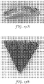
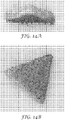
- 238000000879 optical micrograph Methods 0.000 description 7
- 229910052682 stishovite Inorganic materials 0.000 description 7
- 229910052905 tridymite Inorganic materials 0.000 description 7
- 229910001845 yogo sapphire Inorganic materials 0.000 description 7
- 239000011787 zinc oxide Substances 0.000 description 7
- 235000014692 zinc oxide Nutrition 0.000 description 7
- 229910052782 aluminium Inorganic materials 0.000 description 6
- XAGFODPZIPBFFR-UHFFFAOYSA-N aluminium Chemical compound [Al] XAGFODPZIPBFFR-UHFFFAOYSA-N 0.000 description 6
- 229920003180 amino resin Polymers 0.000 description 6
- 239000010949 copper Substances 0.000 description 6
- 239000007788 liquid Substances 0.000 description 6
- FUJCRWPEOMXPAD-UHFFFAOYSA-N lithium oxide Chemical compound [Li+].[Li+].[O-2] FUJCRWPEOMXPAD-UHFFFAOYSA-N 0.000 description 6
- XLYOFNOQVPJJNP-UHFFFAOYSA-N water Substances O XLYOFNOQVPJJNP-UHFFFAOYSA-N 0.000 description 6
- 229910011255 B2O3 Inorganic materials 0.000 description 5
- 239000004743 Polypropylene Substances 0.000 description 5
- BRPQOXSCLDDYGP-UHFFFAOYSA-N calcium oxide Chemical compound [O-2].[Ca+2] BRPQOXSCLDDYGP-UHFFFAOYSA-N 0.000 description 5
- 238000001035 drying Methods 0.000 description 5
- 239000003822 epoxy resin Substances 0.000 description 5
- 230000005308 ferrimagnetism Effects 0.000 description 5
- 239000002241 glass-ceramic Substances 0.000 description 5
- AXZKOIWUVFPNLO-UHFFFAOYSA-N magnesium;oxygen(2-) Chemical compound [O-2].[Mg+2] AXZKOIWUVFPNLO-UHFFFAOYSA-N 0.000 description 5
- 239000005011 phenolic resin Substances 0.000 description 5
- 229920001568 phenolic resin Polymers 0.000 description 5
- 238000005240 physical vapour deposition Methods 0.000 description 5
- 229920000647 polyepoxide Polymers 0.000 description 5
- 229920001155 polypropylene Polymers 0.000 description 5
- 229910001950 potassium oxide Inorganic materials 0.000 description 5
- 229910001948 sodium oxide Inorganic materials 0.000 description 5
- 238000005507 spraying Methods 0.000 description 5
- KXGFMDJXCMQABM-UHFFFAOYSA-N 2-methoxy-6-methylphenol Chemical compound [CH]OC1=CC=CC([CH])=C1O KXGFMDJXCMQABM-UHFFFAOYSA-N 0.000 description 4
- 239000004925 Acrylic resin Substances 0.000 description 4
- 229920000178 Acrylic resin Polymers 0.000 description 4
- 229910000531 Co alloy Inorganic materials 0.000 description 4
- RYGMFSIKBFXOCR-UHFFFAOYSA-N Copper Chemical compound [Cu] RYGMFSIKBFXOCR-UHFFFAOYSA-N 0.000 description 4
- PWHULOQIROXLJO-UHFFFAOYSA-N Manganese Chemical compound [Mn] PWHULOQIROXLJO-UHFFFAOYSA-N 0.000 description 4
- 229910000990 Ni alloy Inorganic materials 0.000 description 4
- RTAQQCXQSZGOHL-UHFFFAOYSA-N Titanium Chemical compound [Ti] RTAQQCXQSZGOHL-UHFFFAOYSA-N 0.000 description 4
- MCMNRKCIXSYSNV-UHFFFAOYSA-N Zirconium dioxide Chemical compound O=[Zr]=O MCMNRKCIXSYSNV-UHFFFAOYSA-N 0.000 description 4
- 239000006061 abrasive grain Substances 0.000 description 4
- 229910000828 alnico Inorganic materials 0.000 description 4
- QVQLCTNNEUAWMS-UHFFFAOYSA-N barium oxide Chemical compound [Ba]=O QVQLCTNNEUAWMS-UHFFFAOYSA-N 0.000 description 4
- 229910052802 copper Inorganic materials 0.000 description 4
- 230000005294 ferromagnetic effect Effects 0.000 description 4
- 238000010304 firing Methods 0.000 description 4
- 238000010438 heat treatment Methods 0.000 description 4
- JEIPFZHSYJVQDO-UHFFFAOYSA-N iron(III) oxide Inorganic materials O=[Fe]O[Fe]=O JEIPFZHSYJVQDO-UHFFFAOYSA-N 0.000 description 4
- 229910000833 kovar Inorganic materials 0.000 description 4
- 229910052748 manganese Inorganic materials 0.000 description 4
- 239000011572 manganese Substances 0.000 description 4
- 229910044991 metal oxide Inorganic materials 0.000 description 4
- 150000002739 metals Chemical class 0.000 description 4
- 230000004044 response Effects 0.000 description 4
- 239000002904 solvent Substances 0.000 description 4
- 229920002803 thermoplastic polyurethane Polymers 0.000 description 4
- 239000010936 titanium Substances 0.000 description 4
- 229910052719 titanium Inorganic materials 0.000 description 4
- WSFSSNUMVMOOMR-UHFFFAOYSA-N Formaldehyde Chemical compound O=C WSFSSNUMVMOOMR-UHFFFAOYSA-N 0.000 description 3
- OKKJLVBELUTLKV-UHFFFAOYSA-N Methanol Chemical compound OC OKKJLVBELUTLKV-UHFFFAOYSA-N 0.000 description 3
- KWYUFKZDYYNOTN-UHFFFAOYSA-M Potassium hydroxide Chemical compound [OH-].[K+] KWYUFKZDYYNOTN-UHFFFAOYSA-M 0.000 description 3
- 238000013459 approach Methods 0.000 description 3
- 230000008901 benefit Effects 0.000 description 3
- 229910052810 boron oxide Inorganic materials 0.000 description 3
- 230000000052 comparative effect Effects 0.000 description 3
- 239000002131 composite material Substances 0.000 description 3
- 229910001610 cryolite Inorganic materials 0.000 description 3
- 239000011222 crystalline ceramic Substances 0.000 description 3
- 229910002106 crystalline ceramic Inorganic materials 0.000 description 3
- QDOXWKRWXJOMAK-UHFFFAOYSA-N dichromium trioxide Chemical compound O=[Cr]O[Cr]=O QDOXWKRWXJOMAK-UHFFFAOYSA-N 0.000 description 3
- XUCJHNOBJLKZNU-UHFFFAOYSA-M dilithium;hydroxide Chemical compound [Li+].[Li+].[OH-] XUCJHNOBJLKZNU-UHFFFAOYSA-M 0.000 description 3
- 239000006185 dispersion Substances 0.000 description 3
- 230000005307 ferromagnetism Effects 0.000 description 3
- 238000000227 grinding Methods 0.000 description 3
- LNEPOXFFQSENCJ-UHFFFAOYSA-N haloperidol Chemical compound C1CC(O)(C=2C=CC(Cl)=CC=2)CCN1CCCC(=O)C1=CC=C(F)C=C1 LNEPOXFFQSENCJ-UHFFFAOYSA-N 0.000 description 3
- 229910001947 lithium oxide Inorganic materials 0.000 description 3
- 229910001092 metal group alloy Inorganic materials 0.000 description 3
- 150000004706 metal oxides Chemical class 0.000 description 3
- 229910001172 neodymium magnet Inorganic materials 0.000 description 3
- 239000000843 powder Substances 0.000 description 3
- 230000008569 process Effects 0.000 description 3
- 230000005855 radiation Effects 0.000 description 3
- 239000005368 silicate glass Substances 0.000 description 3
- 239000010703 silicon Substances 0.000 description 3
- IJGRMHOSHXDMSA-UHFFFAOYSA-N Atomic nitrogen Chemical compound N#N IJGRMHOSHXDMSA-UHFFFAOYSA-N 0.000 description 2
- 229910052692 Dysprosium Inorganic materials 0.000 description 2
- LFQSCWFLJHTTHZ-UHFFFAOYSA-N Ethanol Chemical compound CCO LFQSCWFLJHTTHZ-UHFFFAOYSA-N 0.000 description 2
- 229910052688 Gadolinium Inorganic materials 0.000 description 2
- 229910052689 Holmium Inorganic materials 0.000 description 2
- UQSXHKLRYXJYBZ-UHFFFAOYSA-N Iron oxide Chemical compound [Fe]=O UQSXHKLRYXJYBZ-UHFFFAOYSA-N 0.000 description 2
- FYYHWMGAXLPEAU-UHFFFAOYSA-N Magnesium Chemical compound [Mg] FYYHWMGAXLPEAU-UHFFFAOYSA-N 0.000 description 2
- 229910016964 MnSb Inorganic materials 0.000 description 2
- 229910017034 MnSn Inorganic materials 0.000 description 2
- LRHPLDYGYMQRHN-UHFFFAOYSA-N N-Butanol Chemical compound CCCCO LRHPLDYGYMQRHN-UHFFFAOYSA-N 0.000 description 2
- OAICVXFJPJFONN-UHFFFAOYSA-N Phosphorus Chemical compound [P] OAICVXFJPJFONN-UHFFFAOYSA-N 0.000 description 2
- 229910000676 Si alloy Inorganic materials 0.000 description 2
- XUIMIQQOPSSXEZ-UHFFFAOYSA-N Silicon Chemical compound [Si] XUIMIQQOPSSXEZ-UHFFFAOYSA-N 0.000 description 2
- 229910000612 Sm alloy Inorganic materials 0.000 description 2
- CDBYLPFSWZWCQE-UHFFFAOYSA-L Sodium Carbonate Chemical compound [Na+].[Na+].[O-]C([O-])=O CDBYLPFSWZWCQE-UHFFFAOYSA-L 0.000 description 2
- 229910001308 Zinc ferrite Inorganic materials 0.000 description 2
- ADCOVFLJGNWWNZ-UHFFFAOYSA-N antimony trioxide Chemical compound O=[Sb]O[Sb]=O ADCOVFLJGNWWNZ-UHFFFAOYSA-N 0.000 description 2
- 229910000877 bismanol Inorganic materials 0.000 description 2
- JCXGWMGPZLAOME-UHFFFAOYSA-N bismuth atom Chemical compound [Bi] JCXGWMGPZLAOME-UHFFFAOYSA-N 0.000 description 2
- AYTAKQFHWFYBMA-UHFFFAOYSA-N chromium dioxide Chemical compound O=[Cr]=O AYTAKQFHWFYBMA-UHFFFAOYSA-N 0.000 description 2
- 238000010276 construction Methods 0.000 description 2
- 238000001816 cooling Methods 0.000 description 2
- 230000001186 cumulative effect Effects 0.000 description 2
- 239000008367 deionised water Substances 0.000 description 2
- 229910021641 deionized water Inorganic materials 0.000 description 2
- KBQHZAAAGSGFKK-UHFFFAOYSA-N dysprosium atom Chemical compound [Dy] KBQHZAAAGSGFKK-UHFFFAOYSA-N 0.000 description 2
- 229910001940 europium oxide Inorganic materials 0.000 description 2
- AEBZCFFCDTZXHP-UHFFFAOYSA-N europium(3+);oxygen(2-) Chemical compound [O-2].[O-2].[O-2].[Eu+3].[Eu+3] AEBZCFFCDTZXHP-UHFFFAOYSA-N 0.000 description 2
- 239000010433 feldspar Substances 0.000 description 2
- 229910000830 fernico Inorganic materials 0.000 description 2
- 229910000977 fernicos II Inorganic materials 0.000 description 2
- 230000005293 ferrimagnetic effect Effects 0.000 description 2
- 239000002902 ferrimagnetic material Substances 0.000 description 2
- 239000003302 ferromagnetic material Substances 0.000 description 2
- UIWYJDYFSGRHKR-UHFFFAOYSA-N gadolinium atom Chemical compound [Gd] UIWYJDYFSGRHKR-UHFFFAOYSA-N 0.000 description 2
- 239000002223 garnet Substances 0.000 description 2
- 229910001291 heusler alloy Inorganic materials 0.000 description 2
- KJZYNXUDTRRSPN-UHFFFAOYSA-N holmium atom Chemical compound [Ho] KJZYNXUDTRRSPN-UHFFFAOYSA-N 0.000 description 2
- AMWRITDGCCNYAT-UHFFFAOYSA-L hydroxy(oxo)manganese;manganese Chemical compound [Mn].O[Mn]=O.O[Mn]=O AMWRITDGCCNYAT-UHFFFAOYSA-L 0.000 description 2
- SZVJSHCCFOBDDC-UHFFFAOYSA-N iron(II,III) oxide Inorganic materials O=[Fe]O[Fe]O[Fe]=O SZVJSHCCFOBDDC-UHFFFAOYSA-N 0.000 description 2
- 239000011777 magnesium Substances 0.000 description 2
- 229910052749 magnesium Inorganic materials 0.000 description 2
- 239000000696 magnetic material Substances 0.000 description 2
- 230000005415 magnetization Effects 0.000 description 2
- NUJOXMJBOLGQSY-UHFFFAOYSA-N manganese dioxide Chemical compound O=[Mn]=O NUJOXMJBOLGQSY-UHFFFAOYSA-N 0.000 description 2
- 238000002156 mixing Methods 0.000 description 2
- 238000000465 moulding Methods 0.000 description 2
- NQNBVCBUOCNRFZ-UHFFFAOYSA-N nickel ferrite Chemical compound [Ni]=O.O=[Fe]O[Fe]=O NQNBVCBUOCNRFZ-UHFFFAOYSA-N 0.000 description 2
- 239000002667 nucleating agent Substances 0.000 description 2
- AJCDFVKYMIUXCR-UHFFFAOYSA-N oxobarium;oxo(oxoferriooxy)iron Chemical compound [Ba]=O.O=[Fe]O[Fe]=O.O=[Fe]O[Fe]=O.O=[Fe]O[Fe]=O.O=[Fe]O[Fe]=O.O=[Fe]O[Fe]=O.O=[Fe]O[Fe]=O AJCDFVKYMIUXCR-UHFFFAOYSA-N 0.000 description 2
- 229910000889 permalloy Inorganic materials 0.000 description 2
- ISWSIDIOOBJBQZ-UHFFFAOYSA-N phenol group Chemical group C1(=CC=CC=C1)O ISWSIDIOOBJBQZ-UHFFFAOYSA-N 0.000 description 2
- 229910052698 phosphorus Inorganic materials 0.000 description 2
- 239000011574 phosphorus Substances 0.000 description 2
- 239000000049 pigment Substances 0.000 description 2
- 239000004033 plastic Substances 0.000 description 2
- 229920003023 plastic Polymers 0.000 description 2
- 238000005498 polishing Methods 0.000 description 2
- 238000002360 preparation method Methods 0.000 description 2
- 239000010453 quartz Substances 0.000 description 2
- 229910000702 sendust Inorganic materials 0.000 description 2
- HBMJWWWQQXIZIP-UHFFFAOYSA-N silicon carbide Chemical compound [Si+]#[C-] HBMJWWWQQXIZIP-UHFFFAOYSA-N 0.000 description 2
- 235000012239 silicon dioxide Nutrition 0.000 description 2
- 239000007787 solid Substances 0.000 description 2
- 229910052712 strontium Inorganic materials 0.000 description 2
- CIOAGBVUUVVLOB-UHFFFAOYSA-N strontium atom Chemical compound [Sr] CIOAGBVUUVVLOB-UHFFFAOYSA-N 0.000 description 2
- 239000000126 substance Substances 0.000 description 2
- 238000007740 vapor deposition Methods 0.000 description 2
- WGEATSXPYVGFCC-UHFFFAOYSA-N zinc ferrite Chemical compound O=[Zn].O=[Fe]O[Fe]=O WGEATSXPYVGFCC-UHFFFAOYSA-N 0.000 description 2
- XQUPVDVFXZDTLT-UHFFFAOYSA-N 1-[4-[[4-(2,5-dioxopyrrol-1-yl)phenyl]methyl]phenyl]pyrrole-2,5-dione Chemical compound O=C1C=CC(=O)N1C(C=C1)=CC=C1CC1=CC=C(N2C(C=CC2=O)=O)C=C1 XQUPVDVFXZDTLT-UHFFFAOYSA-N 0.000 description 1
- XNWFRZJHXBZDAG-UHFFFAOYSA-N 2-METHOXYETHANOL Chemical compound COCCO XNWFRZJHXBZDAG-UHFFFAOYSA-N 0.000 description 1
- 239000005995 Aluminium silicate Substances 0.000 description 1
- 229910000521 B alloy Inorganic materials 0.000 description 1
- QYEXBYZXHDUPRC-UHFFFAOYSA-N B#[Ti]#B Chemical compound B#[Ti]#B QYEXBYZXHDUPRC-UHFFFAOYSA-N 0.000 description 1
- 229910052580 B4C Inorganic materials 0.000 description 1
- 229910052582 BN Inorganic materials 0.000 description 1
- ZOXJGFHDIHLPTG-UHFFFAOYSA-N Boron Chemical compound [B] ZOXJGFHDIHLPTG-UHFFFAOYSA-N 0.000 description 1
- PZNSFCLAULLKQX-UHFFFAOYSA-N Boron nitride Chemical compound N#B PZNSFCLAULLKQX-UHFFFAOYSA-N 0.000 description 1
- OKTJSMMVPCPJKN-UHFFFAOYSA-N Carbon Chemical compound [C] OKTJSMMVPCPJKN-UHFFFAOYSA-N 0.000 description 1
- 229910000975 Carbon steel Inorganic materials 0.000 description 1
- FBPFZTCFMRRESA-KVTDHHQDSA-N D-Mannitol Chemical compound OC[C@@H](O)[C@@H](O)[C@H](O)[C@H](O)CO FBPFZTCFMRRESA-KVTDHHQDSA-N 0.000 description 1
- XTHFKEDIFFGKHM-UHFFFAOYSA-N Dimethoxyethane Chemical compound COCCOC XTHFKEDIFFGKHM-UHFFFAOYSA-N 0.000 description 1
- 239000004593 Epoxy Substances 0.000 description 1
- 206010073306 Exposure to radiation Diseases 0.000 description 1
- DGAQECJNVWCQMB-PUAWFVPOSA-M Ilexoside XXIX Chemical compound C[C@@H]1CC[C@@]2(CC[C@@]3(C(=CC[C@H]4[C@]3(CC[C@@H]5[C@@]4(CC[C@@H](C5(C)C)OS(=O)(=O)[O-])C)C)[C@@H]2[C@]1(C)O)C)C(=O)O[C@H]6[C@@H]([C@H]([C@@H]([C@H](O6)CO)O)O)O.[Na+] DGAQECJNVWCQMB-PUAWFVPOSA-M 0.000 description 1
- 229910000502 Li-aluminosilicate Inorganic materials 0.000 description 1
- 235000019738 Limestone Nutrition 0.000 description 1
- 229930195725 Mannitol Natural products 0.000 description 1
- 229920000877 Melamine resin Polymers 0.000 description 1
- 241000276489 Merlangius merlangus Species 0.000 description 1
- 229910016987 MnOFe2O3 Inorganic materials 0.000 description 1
- 229910000583 Nd alloy Inorganic materials 0.000 description 1
- 229910052779 Neodymium Inorganic materials 0.000 description 1
- 229910004291 O3.2SiO2 Inorganic materials 0.000 description 1
- 229910004288 O3.5SiO2 Inorganic materials 0.000 description 1
- 229920002472 Starch Polymers 0.000 description 1
- 229910000831 Steel Inorganic materials 0.000 description 1
- CZMRCDWAGMRECN-UGDNZRGBSA-N Sucrose Chemical compound O[C@H]1[C@H](O)[C@@H](CO)O[C@@]1(CO)O[C@@H]1[C@H](O)[C@@H](O)[C@H](O)[C@@H](CO)O1 CZMRCDWAGMRECN-UGDNZRGBSA-N 0.000 description 1
- 229930006000 Sucrose Natural products 0.000 description 1
- NINIDFKCEFEMDL-UHFFFAOYSA-N Sulfur Chemical compound [S] NINIDFKCEFEMDL-UHFFFAOYSA-N 0.000 description 1
- 229910033181 TiB2 Inorganic materials 0.000 description 1
- WGLPBDUCMAPZCE-UHFFFAOYSA-N Trioxochromium Chemical compound O=[Cr](=O)=O WGLPBDUCMAPZCE-UHFFFAOYSA-N 0.000 description 1
- 229920001807 Urea-formaldehyde Polymers 0.000 description 1
- 229920002143 Vulcanized fibre Polymers 0.000 description 1
- 229910009493 Y3Fe5O12 Inorganic materials 0.000 description 1
- HCHKCACWOHOZIP-UHFFFAOYSA-N Zinc Chemical compound [Zn] HCHKCACWOHOZIP-UHFFFAOYSA-N 0.000 description 1
- NIXOWILDQLNWCW-UHFFFAOYSA-N acrylic acid group Chemical group C(C=C)(=O)O NIXOWILDQLNWCW-UHFFFAOYSA-N 0.000 description 1
- 229920005822 acrylic binder Polymers 0.000 description 1
- 239000000853 adhesive Substances 0.000 description 1
- 230000001070 adhesive effect Effects 0.000 description 1
- 150000001298 alcohols Chemical class 0.000 description 1
- HZVVJJIYJKGMFL-UHFFFAOYSA-N almasilate Chemical compound O.[Mg+2].[Al+3].[Al+3].O[Si](O)=O.O[Si](O)=O HZVVJJIYJKGMFL-UHFFFAOYSA-N 0.000 description 1
- 235000012211 aluminium silicate Nutrition 0.000 description 1
- 229910000323 aluminium silicate Inorganic materials 0.000 description 1
- CNLWCVNCHLKFHK-UHFFFAOYSA-N aluminum;lithium;dioxido(oxo)silane Chemical compound [Li+].[Al+3].[O-][Si]([O-])=O.[O-][Si]([O-])=O CNLWCVNCHLKFHK-UHFFFAOYSA-N 0.000 description 1
- 229910052661 anorthite Inorganic materials 0.000 description 1
- QVGXLLKOCUKJST-UHFFFAOYSA-N atomic oxygen Chemical compound [O] QVGXLLKOCUKJST-UHFFFAOYSA-N 0.000 description 1
- 239000011324 bead Substances 0.000 description 1
- 230000015572 biosynthetic process Effects 0.000 description 1
- 229910021418 black silicon Inorganic materials 0.000 description 1
- 229910021538 borax Inorganic materials 0.000 description 1
- KGBXLFKZBHKPEV-UHFFFAOYSA-N boric acid Chemical compound OB(O)O KGBXLFKZBHKPEV-UHFFFAOYSA-N 0.000 description 1
- 239000004327 boric acid Substances 0.000 description 1
- INAHAJYZKVIDIZ-UHFFFAOYSA-N boron carbide Chemical compound B12B3B4C32B41 INAHAJYZKVIDIZ-UHFFFAOYSA-N 0.000 description 1
- QHIWVLPBUQWDMQ-UHFFFAOYSA-N butyl prop-2-enoate;methyl 2-methylprop-2-enoate;prop-2-enoic acid Chemical compound OC(=O)C=C.COC(=O)C(C)=C.CCCCOC(=O)C=C QHIWVLPBUQWDMQ-UHFFFAOYSA-N 0.000 description 1
- 239000000404 calcium aluminium silicate Substances 0.000 description 1
- 235000012215 calcium aluminium silicate Nutrition 0.000 description 1
- WNCYAPRTYDMSFP-UHFFFAOYSA-N calcium aluminosilicate Chemical compound [Al+3].[Al+3].[Ca+2].[O-][Si]([O-])=O.[O-][Si]([O-])=O.[O-][Si]([O-])=O.[O-][Si]([O-])=O WNCYAPRTYDMSFP-UHFFFAOYSA-N 0.000 description 1
- 229940078583 calcium aluminosilicate Drugs 0.000 description 1
- 235000012241 calcium silicate Nutrition 0.000 description 1
- 229910052918 calcium silicate Inorganic materials 0.000 description 1
- OYACROKNLOSFPA-UHFFFAOYSA-N calcium;dioxido(oxo)silane Chemical compound [Ca+2].[O-][Si]([O-])=O OYACROKNLOSFPA-UHFFFAOYSA-N 0.000 description 1
- 229910052799 carbon Inorganic materials 0.000 description 1
- 239000010962 carbon steel Substances 0.000 description 1
- 239000003054 catalyst Substances 0.000 description 1
- 229910010293 ceramic material Inorganic materials 0.000 description 1
- CETPSERCERDGAM-UHFFFAOYSA-N ceric oxide Chemical compound O=[Ce]=O CETPSERCERDGAM-UHFFFAOYSA-N 0.000 description 1
- 229910000422 cerium(IV) oxide Inorganic materials 0.000 description 1
- 230000008859 change Effects 0.000 description 1
- 239000003153 chemical reaction reagent Substances 0.000 description 1
- 229910000423 chromium oxide Inorganic materials 0.000 description 1
- 239000004927 clay Substances 0.000 description 1
- 229910000428 cobalt oxide Inorganic materials 0.000 description 1
- IVMYJDGYRUAWML-UHFFFAOYSA-N cobalt(ii) oxide Chemical compound [Co]=O IVMYJDGYRUAWML-UHFFFAOYSA-N 0.000 description 1
- 239000003086 colorant Substances 0.000 description 1
- 150000001875 compounds Chemical class 0.000 description 1
- 229910052878 cordierite Inorganic materials 0.000 description 1
- 230000007797 corrosion Effects 0.000 description 1
- 238000005260 corrosion Methods 0.000 description 1
- 238000004132 cross linking Methods 0.000 description 1
- 239000013078 crystal Substances 0.000 description 1
- 239000002173 cutting fluid Substances 0.000 description 1
- 239000013530 defoamer Substances 0.000 description 1
- 230000000994 depressogenic effect Effects 0.000 description 1
- 238000013461 design Methods 0.000 description 1
- GWWPLLOVYSCJIO-UHFFFAOYSA-N dialuminum;calcium;disilicate Chemical compound [Al+3].[Al+3].[Ca+2].[O-][Si]([O-])([O-])[O-].[O-][Si]([O-])([O-])[O-] GWWPLLOVYSCJIO-UHFFFAOYSA-N 0.000 description 1
- 239000010432 diamond Substances 0.000 description 1
- 229910003460 diamond Inorganic materials 0.000 description 1
- SBZXBUIDTXKZTM-UHFFFAOYSA-N diglyme Chemical compound COCCOCCOC SBZXBUIDTXKZTM-UHFFFAOYSA-N 0.000 description 1
- 238000007865 diluting Methods 0.000 description 1
- JSKIRARMQDRGJZ-UHFFFAOYSA-N dimagnesium dioxido-bis[(1-oxido-3-oxo-2,4,6,8,9-pentaoxa-1,3-disila-5,7-dialuminabicyclo[3.3.1]nonan-7-yl)oxy]silane Chemical compound [Mg++].[Mg++].[O-][Si]([O-])(O[Al]1O[Al]2O[Si](=O)O[Si]([O-])(O1)O2)O[Al]1O[Al]2O[Si](=O)O[Si]([O-])(O1)O2 JSKIRARMQDRGJZ-UHFFFAOYSA-N 0.000 description 1
- HNPSIPDUKPIQMN-UHFFFAOYSA-N dioxosilane;oxo(oxoalumanyloxy)alumane Chemical compound O=[Si]=O.O=[Al]O[Al]=O HNPSIPDUKPIQMN-UHFFFAOYSA-N 0.000 description 1
- 238000003618 dip coating Methods 0.000 description 1
- 239000002270 dispersing agent Substances 0.000 description 1
- 238000009826 distribution Methods 0.000 description 1
- 239000010459 dolomite Substances 0.000 description 1
- 229910000514 dolomite Inorganic materials 0.000 description 1
- 239000000428 dust Substances 0.000 description 1
- 230000000694 effects Effects 0.000 description 1
- 238000009503 electrostatic coating Methods 0.000 description 1
- 238000005516 engineering process Methods 0.000 description 1
- 150000002170 ethers Chemical class 0.000 description 1
- 239000004744 fabric Substances 0.000 description 1
- 238000011049 filling Methods 0.000 description 1
- 239000012847 fine chemical Substances 0.000 description 1
- 230000004907 flux Effects 0.000 description 1
- 230000004927 fusion Effects 0.000 description 1
- 229910001676 gahnite Inorganic materials 0.000 description 1
- 229910001678 gehlenite Inorganic materials 0.000 description 1
- 239000003365 glass fiber Substances 0.000 description 1
- 239000003292 glue Substances 0.000 description 1
- 239000007943 implant Substances 0.000 description 1
- 230000002401 inhibitory effect Effects 0.000 description 1
- 239000003999 initiator Substances 0.000 description 1
- 229910010272 inorganic material Inorganic materials 0.000 description 1
- 239000011147 inorganic material Substances 0.000 description 1
- 239000001034 iron oxide pigment Substances 0.000 description 1
- MTRJKZUDDJZTLA-UHFFFAOYSA-N iron yttrium Chemical compound [Fe].[Y] MTRJKZUDDJZTLA-UHFFFAOYSA-N 0.000 description 1
- ZFSLODLOARCGLH-UHFFFAOYSA-N isocyanuric acid Chemical compound OC1=NC(O)=NC(O)=N1 ZFSLODLOARCGLH-UHFFFAOYSA-N 0.000 description 1
- NLYAJNPCOHFWQQ-UHFFFAOYSA-N kaolin Chemical compound O.O.O=[Al]O[Si](=O)O[Si](=O)O[Al]=O NLYAJNPCOHFWQQ-UHFFFAOYSA-N 0.000 description 1
- 239000006028 limestone Substances 0.000 description 1
- 230000000670 limiting effect Effects 0.000 description 1
- 239000000314 lubricant Substances 0.000 description 1
- 239000006249 magnetic particle Substances 0.000 description 1
- 230000005389 magnetism Effects 0.000 description 1
- 238000001755 magnetron sputter deposition Methods 0.000 description 1
- 235000010355 mannitol Nutrition 0.000 description 1
- 239000000594 mannitol Substances 0.000 description 1
- 230000000873 masking effect Effects 0.000 description 1
- 238000010297 mechanical methods and process Methods 0.000 description 1
- 239000007769 metal material Substances 0.000 description 1
- 238000001465 metallisation Methods 0.000 description 1
- 229910052752 metalloid Inorganic materials 0.000 description 1
- 150000002738 metalloids Chemical class 0.000 description 1
- 238000003801 milling Methods 0.000 description 1
- 238000012986 modification Methods 0.000 description 1
- 230000004048 modification Effects 0.000 description 1
- 239000006082 mold release agent Substances 0.000 description 1
- 239000000178 monomer Substances 0.000 description 1
- QEFYFXOXNSNQGX-UHFFFAOYSA-N neodymium atom Chemical compound [Nd] QEFYFXOXNSNQGX-UHFFFAOYSA-N 0.000 description 1
- 229910052757 nitrogen Inorganic materials 0.000 description 1
- 239000003921 oil Substances 0.000 description 1
- 229920000620 organic polymer Polymers 0.000 description 1
- 229910052760 oxygen Inorganic materials 0.000 description 1
- 239000001301 oxygen Substances 0.000 description 1
- 238000010422 painting Methods 0.000 description 1
- 238000011056 performance test Methods 0.000 description 1
- 230000000704 physical effect Effects 0.000 description 1
- 229920003192 poly(bis maleimide) Polymers 0.000 description 1
- 239000004848 polyfunctional curative Substances 0.000 description 1
- 229920000642 polymer Polymers 0.000 description 1
- 238000012545 processing Methods 0.000 description 1
- BDERNNFJNOPAEC-UHFFFAOYSA-N propan-1-ol Chemical compound CCCO BDERNNFJNOPAEC-UHFFFAOYSA-N 0.000 description 1
- 239000002994 raw material Substances 0.000 description 1
- 230000002829 reductive effect Effects 0.000 description 1
- 239000002990 reinforced plastic Substances 0.000 description 1
- 229920003987 resole Polymers 0.000 description 1
- 239000006254 rheological additive Substances 0.000 description 1
- 229910052710 silicon Inorganic materials 0.000 description 1
- 229910010271 silicon carbide Inorganic materials 0.000 description 1
- 229910052814 silicon oxide Inorganic materials 0.000 description 1
- 238000005245 sintering Methods 0.000 description 1
- 239000000344 soap Substances 0.000 description 1
- 239000011734 sodium Substances 0.000 description 1
- 229910052708 sodium Inorganic materials 0.000 description 1
- 229910000029 sodium carbonate Inorganic materials 0.000 description 1
- 235000017550 sodium carbonate Nutrition 0.000 description 1
- 239000004328 sodium tetraborate Substances 0.000 description 1
- 235000010339 sodium tetraborate Nutrition 0.000 description 1
- BPILDHPJSYVNAF-UHFFFAOYSA-M sodium;diiodomethanesulfonate Chemical compound [Na+].[O-]S(=O)(=O)C(I)I BPILDHPJSYVNAF-UHFFFAOYSA-M 0.000 description 1
- 229910052642 spodumene Inorganic materials 0.000 description 1
- 230000002269 spontaneous effect Effects 0.000 description 1
- 229910001220 stainless steel Inorganic materials 0.000 description 1
- 239000008107 starch Substances 0.000 description 1
- 235000019698 starch Nutrition 0.000 description 1
- 239000010959 steel Substances 0.000 description 1
- 239000004575 stone Substances 0.000 description 1
- 239000000758 substrate Substances 0.000 description 1
- 239000005720 sucrose Substances 0.000 description 1
- 239000011593 sulfur Substances 0.000 description 1
- 229910052717 sulfur Inorganic materials 0.000 description 1
- 239000004094 surface-active agent Substances 0.000 description 1
- XOLBLPGZBRYERU-UHFFFAOYSA-N tin dioxide Chemical compound O=[Sn]=O XOLBLPGZBRYERU-UHFFFAOYSA-N 0.000 description 1
- 229910001887 tin oxide Inorganic materials 0.000 description 1
- 239000004408 titanium dioxide Substances 0.000 description 1
- OGIDPMRJRNCKJF-UHFFFAOYSA-N titanium oxide Inorganic materials [Ti]=O OGIDPMRJRNCKJF-UHFFFAOYSA-N 0.000 description 1
- MTPVUVINMAGMJL-UHFFFAOYSA-N trimethyl(1,1,2,2,2-pentafluoroethyl)silane Chemical compound C[Si](C)(C)C(F)(F)C(F)(F)F MTPVUVINMAGMJL-UHFFFAOYSA-N 0.000 description 1
- UONOETXJSWQNOL-UHFFFAOYSA-N tungsten carbide Chemical compound [W+]#[C-] UONOETXJSWQNOL-UHFFFAOYSA-N 0.000 description 1
- 150000003673 urethanes Chemical class 0.000 description 1
- 229910052844 willemite Inorganic materials 0.000 description 1
- 239000010456 wollastonite Substances 0.000 description 1
- 229910052882 wollastonite Inorganic materials 0.000 description 1
- 239000002023 wood Substances 0.000 description 1
- 229910052725 zinc Inorganic materials 0.000 description 1
- 239000011701 zinc Substances 0.000 description 1
Images


Classifications
-
- C—CHEMISTRY; METALLURGY
- C09—DYES; PAINTS; POLISHES; NATURAL RESINS; ADHESIVES; COMPOSITIONS NOT OTHERWISE PROVIDED FOR; APPLICATIONS OF MATERIALS NOT OTHERWISE PROVIDED FOR
- C09K—MATERIALS FOR MISCELLANEOUS APPLICATIONS, NOT PROVIDED FOR ELSEWHERE
- C09K3/00—Materials not provided for elsewhere
- C09K3/14—Anti-slip materials; Abrasives
- C09K3/1436—Composite particles, e.g. coated particles
-
- B—PERFORMING OPERATIONS; TRANSPORTING
- B24—GRINDING; POLISHING
- B24D—TOOLS FOR GRINDING, BUFFING OR SHARPENING
- B24D11/00—Constructional features of flexible abrasive materials; Special features in the manufacture of such materials
-
- C—CHEMISTRY; METALLURGY
- C04—CEMENTS; CONCRETE; ARTIFICIAL STONE; CERAMICS; REFRACTORIES
- C04B—LIME, MAGNESIA; SLAG; CEMENTS; COMPOSITIONS THEREOF, e.g. MORTARS, CONCRETE OR LIKE BUILDING MATERIALS; ARTIFICIAL STONE; CERAMICS; REFRACTORIES; TREATMENT OF NATURAL STONE
- C04B35/00—Shaped ceramic products characterised by their composition; Ceramics compositions; Processing powders of inorganic compounds preparatory to the manufacturing of ceramic products
- C04B35/01—Shaped ceramic products characterised by their composition; Ceramics compositions; Processing powders of inorganic compounds preparatory to the manufacturing of ceramic products based on oxide ceramics
- C04B35/10—Shaped ceramic products characterised by their composition; Ceramics compositions; Processing powders of inorganic compounds preparatory to the manufacturing of ceramic products based on oxide ceramics based on aluminium oxide
- C04B35/111—Fine ceramics
- C04B35/1115—Minute sintered entities, e.g. sintered abrasive grains or shaped particles such as platelets
-
- C—CHEMISTRY; METALLURGY
- C04—CEMENTS; CONCRETE; ARTIFICIAL STONE; CERAMICS; REFRACTORIES
- C04B—LIME, MAGNESIA; SLAG; CEMENTS; COMPOSITIONS THEREOF, e.g. MORTARS, CONCRETE OR LIKE BUILDING MATERIALS; ARTIFICIAL STONE; CERAMICS; REFRACTORIES; TREATMENT OF NATURAL STONE
- C04B35/00—Shaped ceramic products characterised by their composition; Ceramics compositions; Processing powders of inorganic compounds preparatory to the manufacturing of ceramic products
- C04B35/622—Forming processes; Processing powders of inorganic compounds preparatory to the manufacturing of ceramic products
- C04B35/624—Sol-gel processing
-
- C—CHEMISTRY; METALLURGY
- C04—CEMENTS; CONCRETE; ARTIFICIAL STONE; CERAMICS; REFRACTORIES
- C04B—LIME, MAGNESIA; SLAG; CEMENTS; COMPOSITIONS THEREOF, e.g. MORTARS, CONCRETE OR LIKE BUILDING MATERIALS; ARTIFICIAL STONE; CERAMICS; REFRACTORIES; TREATMENT OF NATURAL STONE
- C04B35/00—Shaped ceramic products characterised by their composition; Ceramics compositions; Processing powders of inorganic compounds preparatory to the manufacturing of ceramic products
- C04B35/622—Forming processes; Processing powders of inorganic compounds preparatory to the manufacturing of ceramic products
- C04B35/626—Preparing or treating the powders individually or as batches ; preparing or treating macroscopic reinforcing agents for ceramic products, e.g. fibres; mechanical aspects section B
- C04B35/628—Coating the powders or the macroscopic reinforcing agents
- C04B35/62802—Powder coating materials
- C04B35/62805—Oxide ceramics
- C04B35/62815—Rare earth metal oxides
-
- C—CHEMISTRY; METALLURGY
- C04—CEMENTS; CONCRETE; ARTIFICIAL STONE; CERAMICS; REFRACTORIES
- C04B—LIME, MAGNESIA; SLAG; CEMENTS; COMPOSITIONS THEREOF, e.g. MORTARS, CONCRETE OR LIKE BUILDING MATERIALS; ARTIFICIAL STONE; CERAMICS; REFRACTORIES; TREATMENT OF NATURAL STONE
- C04B35/00—Shaped ceramic products characterised by their composition; Ceramics compositions; Processing powders of inorganic compounds preparatory to the manufacturing of ceramic products
- C04B35/622—Forming processes; Processing powders of inorganic compounds preparatory to the manufacturing of ceramic products
- C04B35/626—Preparing or treating the powders individually or as batches ; preparing or treating macroscopic reinforcing agents for ceramic products, e.g. fibres; mechanical aspects section B
- C04B35/628—Coating the powders or the macroscopic reinforcing agents
- C04B35/62802—Powder coating materials
- C04B35/62805—Oxide ceramics
- C04B35/62826—Iron group metal oxides
-
- C—CHEMISTRY; METALLURGY
- C04—CEMENTS; CONCRETE; ARTIFICIAL STONE; CERAMICS; REFRACTORIES
- C04B—LIME, MAGNESIA; SLAG; CEMENTS; COMPOSITIONS THEREOF, e.g. MORTARS, CONCRETE OR LIKE BUILDING MATERIALS; ARTIFICIAL STONE; CERAMICS; REFRACTORIES; TREATMENT OF NATURAL STONE
- C04B35/00—Shaped ceramic products characterised by their composition; Ceramics compositions; Processing powders of inorganic compounds preparatory to the manufacturing of ceramic products
- C04B35/622—Forming processes; Processing powders of inorganic compounds preparatory to the manufacturing of ceramic products
- C04B35/626—Preparing or treating the powders individually or as batches ; preparing or treating macroscopic reinforcing agents for ceramic products, e.g. fibres; mechanical aspects section B
- C04B35/628—Coating the powders or the macroscopic reinforcing agents
- C04B35/62886—Coating the powders or the macroscopic reinforcing agents by wet chemical techniques
-
- C—CHEMISTRY; METALLURGY
- C08—ORGANIC MACROMOLECULAR COMPOUNDS; THEIR PREPARATION OR CHEMICAL WORKING-UP; COMPOSITIONS BASED THEREON
- C08G—MACROMOLECULAR COMPOUNDS OBTAINED OTHERWISE THAN BY REACTIONS ONLY INVOLVING UNSATURATED CARBON-TO-CARBON BONDS
- C08G8/00—Condensation polymers of aldehydes or ketones with phenols only
- C08G8/04—Condensation polymers of aldehydes or ketones with phenols only of aldehydes
- C08G8/08—Condensation polymers of aldehydes or ketones with phenols only of aldehydes of formaldehyde, e.g. of formaldehyde formed in situ
- C08G8/10—Condensation polymers of aldehydes or ketones with phenols only of aldehydes of formaldehyde, e.g. of formaldehyde formed in situ with phenol
-
- C—CHEMISTRY; METALLURGY
- C08—ORGANIC MACROMOLECULAR COMPOUNDS; THEIR PREPARATION OR CHEMICAL WORKING-UP; COMPOSITIONS BASED THEREON
- C08K—Use of inorganic or non-macromolecular organic substances as compounding ingredients
- C08K3/00—Use of inorganic substances as compounding ingredients
- C08K3/18—Oxygen-containing compounds, e.g. metal carbonyls
- C08K3/20—Oxides; Hydroxides
- C08K3/22—Oxides; Hydroxides of metals
-
- C—CHEMISTRY; METALLURGY
- C08—ORGANIC MACROMOLECULAR COMPOUNDS; THEIR PREPARATION OR CHEMICAL WORKING-UP; COMPOSITIONS BASED THEREON
- C08K—Use of inorganic or non-macromolecular organic substances as compounding ingredients
- C08K7/00—Use of ingredients characterised by shape
-
- C—CHEMISTRY; METALLURGY
- C08—ORGANIC MACROMOLECULAR COMPOUNDS; THEIR PREPARATION OR CHEMICAL WORKING-UP; COMPOSITIONS BASED THEREON
- C08K—Use of inorganic or non-macromolecular organic substances as compounding ingredients
- C08K9/00—Use of pretreated ingredients
- C08K9/02—Ingredients treated with inorganic substances
-
- C—CHEMISTRY; METALLURGY
- C08—ORGANIC MACROMOLECULAR COMPOUNDS; THEIR PREPARATION OR CHEMICAL WORKING-UP; COMPOSITIONS BASED THEREON
- C08K—Use of inorganic or non-macromolecular organic substances as compounding ingredients
- C08K9/00—Use of pretreated ingredients
- C08K9/04—Ingredients treated with organic substances
-
- C—CHEMISTRY; METALLURGY
- C04—CEMENTS; CONCRETE; ARTIFICIAL STONE; CERAMICS; REFRACTORIES
- C04B—LIME, MAGNESIA; SLAG; CEMENTS; COMPOSITIONS THEREOF, e.g. MORTARS, CONCRETE OR LIKE BUILDING MATERIALS; ARTIFICIAL STONE; CERAMICS; REFRACTORIES; TREATMENT OF NATURAL STONE
- C04B2235/00—Aspects relating to ceramic starting mixtures or sintered ceramic products
- C04B2235/02—Composition of constituents of the starting material or of secondary phases of the final product
- C04B2235/30—Constituents and secondary phases not being of a fibrous nature
- C04B2235/32—Metal oxides, mixed metal oxides, or oxide-forming salts thereof, e.g. carbonates, nitrates, (oxy)hydroxides, chlorides
- C04B2235/3217—Aluminum oxide or oxide forming salts thereof, e.g. bauxite, alpha-alumina
-
- C—CHEMISTRY; METALLURGY
- C04—CEMENTS; CONCRETE; ARTIFICIAL STONE; CERAMICS; REFRACTORIES
- C04B—LIME, MAGNESIA; SLAG; CEMENTS; COMPOSITIONS THEREOF, e.g. MORTARS, CONCRETE OR LIKE BUILDING MATERIALS; ARTIFICIAL STONE; CERAMICS; REFRACTORIES; TREATMENT OF NATURAL STONE
- C04B2235/00—Aspects relating to ceramic starting mixtures or sintered ceramic products
- C04B2235/02—Composition of constituents of the starting material or of secondary phases of the final product
- C04B2235/30—Constituents and secondary phases not being of a fibrous nature
- C04B2235/32—Metal oxides, mixed metal oxides, or oxide-forming salts thereof, e.g. carbonates, nitrates, (oxy)hydroxides, chlorides
- C04B2235/327—Iron group oxides, their mixed metal oxides, or oxide-forming salts thereof
- C04B2235/3272—Iron oxides or oxide forming salts thereof, e.g. hematite, magnetite
-
- C—CHEMISTRY; METALLURGY
- C04—CEMENTS; CONCRETE; ARTIFICIAL STONE; CERAMICS; REFRACTORIES
- C04B—LIME, MAGNESIA; SLAG; CEMENTS; COMPOSITIONS THEREOF, e.g. MORTARS, CONCRETE OR LIKE BUILDING MATERIALS; ARTIFICIAL STONE; CERAMICS; REFRACTORIES; TREATMENT OF NATURAL STONE
- C04B2235/00—Aspects relating to ceramic starting mixtures or sintered ceramic products
- C04B2235/02—Composition of constituents of the starting material or of secondary phases of the final product
- C04B2235/50—Constituents or additives of the starting mixture chosen for their shape or used because of their shape or their physical appearance
- C04B2235/52—Constituents or additives characterised by their shapes
- C04B2235/5292—Flakes, platelets or plates
-
- C—CHEMISTRY; METALLURGY
- C04—CEMENTS; CONCRETE; ARTIFICIAL STONE; CERAMICS; REFRACTORIES
- C04B—LIME, MAGNESIA; SLAG; CEMENTS; COMPOSITIONS THEREOF, e.g. MORTARS, CONCRETE OR LIKE BUILDING MATERIALS; ARTIFICIAL STONE; CERAMICS; REFRACTORIES; TREATMENT OF NATURAL STONE
- C04B2235/00—Aspects relating to ceramic starting mixtures or sintered ceramic products
- C04B2235/70—Aspects relating to sintered or melt-casted ceramic products
- C04B2235/94—Products characterised by their shape
-
- C—CHEMISTRY; METALLURGY
- C04—CEMENTS; CONCRETE; ARTIFICIAL STONE; CERAMICS; REFRACTORIES
- C04B—LIME, MAGNESIA; SLAG; CEMENTS; COMPOSITIONS THEREOF, e.g. MORTARS, CONCRETE OR LIKE BUILDING MATERIALS; ARTIFICIAL STONE; CERAMICS; REFRACTORIES; TREATMENT OF NATURAL STONE
- C04B2235/00—Aspects relating to ceramic starting mixtures or sintered ceramic products
- C04B2235/70—Aspects relating to sintered or melt-casted ceramic products
- C04B2235/96—Properties of ceramic products, e.g. mechanical properties such as strength, toughness, wear resistance
-
- C—CHEMISTRY; METALLURGY
- C08—ORGANIC MACROMOLECULAR COMPOUNDS; THEIR PREPARATION OR CHEMICAL WORKING-UP; COMPOSITIONS BASED THEREON
- C08K—Use of inorganic or non-macromolecular organic substances as compounding ingredients
- C08K3/00—Use of inorganic substances as compounding ingredients
- C08K3/18—Oxygen-containing compounds, e.g. metal carbonyls
- C08K3/20—Oxides; Hydroxides
- C08K3/22—Oxides; Hydroxides of metals
- C08K2003/2227—Oxides; Hydroxides of metals of aluminium
-
- C—CHEMISTRY; METALLURGY
- C08—ORGANIC MACROMOLECULAR COMPOUNDS; THEIR PREPARATION OR CHEMICAL WORKING-UP; COMPOSITIONS BASED THEREON
- C08K—Use of inorganic or non-macromolecular organic substances as compounding ingredients
- C08K2201/00—Specific properties of additives
- C08K2201/01—Magnetic additives
-
- H—ELECTRICITY
- H01—ELECTRIC ELEMENTS
- H01F—MAGNETS; INDUCTANCES; TRANSFORMERS; SELECTION OF MATERIALS FOR THEIR MAGNETIC PROPERTIES
- H01F1/00—Magnets or magnetic bodies characterised by the magnetic materials therefor; Selection of materials for their magnetic properties
- H01F1/01—Magnets or magnetic bodies characterised by the magnetic materials therefor; Selection of materials for their magnetic properties of inorganic materials
- H01F1/03—Magnets or magnetic bodies characterised by the magnetic materials therefor; Selection of materials for their magnetic properties of inorganic materials characterised by their coercivity
- H01F1/0302—Magnets or magnetic bodies characterised by the magnetic materials therefor; Selection of materials for their magnetic properties of inorganic materials characterised by their coercivity characterised by unspecified or heterogeneous hardness or specially adapted for magnetic hardness transitions
Definitions
- the present disclosure broadly relates to abrasive particles, abrasive articles, and methods of making them.
- coated abrasive articles generally have abrasive particles adhered to a backing by a resinous binder material.
- examples include sandpaper and structured abrasives having precisely shaped abrasive composites adhered to a backing.
- the abrasive composites generally include abrasive particles and a resinous binder.
- Bonded abrasive particles include abrasive particles retained in a binder matrix that can be resinous or vitreous. Examples include, grindstones, cutoff wheels, hones, and whetstones.
- coated abrasive articles have been made using techniques such as electrostatic coating of abrasive particles have been used to align crushed abrasive particles with the longitudinal axes perpendicular to the backing.
- shaped abrasive particles have been aligned by mechanical methods as disclosed in U. S. Pat. Appl. Publ. No. 2013/0344786 A1 (Keipert ).
- magnetizable abrasive particles with incomplete magnetizable layers can be manipulated using magnetic fields in ways that differ from abrasive particles having layers over their entire surface to provide various abrasive articles.
- the present disclosure provides a magnetizable abrasive particle comprising a ceramic body having an outer surface, and a magnetizable layer disposed on a portion, but not the entirety, of the outer surface.
- the present disclosure provides a plurality of magnetizable abrasive particles according to the present disclosure.
- the present disclosure provides a plurality of magnetizable abrasive particles according to the present disclosure retained in a binder material.
- ceramic refers to any of various hard, brittle, heat- and corrosion-resistant materials made of at least one metallic element (which may include silicon) combined with oxygen, carbon, nitrogen, or sulfur. Ceramics may be crystalline or polycrystalline, for example.
- ferrimagnetic refers to materials (in bulk) that exhibit ferrimagnetism.
- Ferrimagnetism is a type of permanent magnetism that occurs in solids in which the magnetic fields associated with individual atoms spontaneously align themselves, some parallel, or in the same direction (as in ferromagnetism), and others generally antiparallel, or paired off in opposite directions (as in antifermmagnetism).
- the magnetic behavior of single crystals of ferrimagnetic materials may be attributed to the parallel alignment; the diluting effect of those atoms in the antiparallel arrangement keeps the magnetic strength of these materials generally less than that of purely ferromagnetic solids such as metallic iron.
- Ferrimagnetism occurs chiefly in magnetic oxides known as ferrites.
- the spontaneous alignment that produces ferrimagnetism is entirely disrupted above a temperature called the Curie point, characteristic of each ferrimagnetic material. When the temperature of the material is brought below the Curie point, ferrimagnetism revives.
- ferromagnetic refers to materials (in bulk) that exhibit ferromagnetism. Ferromagnetism is a physical phenomenon in which certain electrically uncharged materials strongly attract others. In contrast to other substances, ferromagnetic materials are magnetized easily, and in strong magnetic fields (e.g., greater than 1000 gauss (1 kG), preferably greater than 3 kG, more preferably greater than 5 kG), and more preferably greater than 7 kG) the magnetization approaches a definite limit called saturation. When a field is applied and then removed, the magnetization does not return to its original value. This phenomenon is referred to as hysteresis. When heated to a certain temperature called the Curie point, which is generally different for each substance, ferromagnetic materials lose their characteristic properties and cease to be magnetic; however, they become ferromagnetic again on cooling.
- Curie point which is generally different for each substance
- magnetic means being ferromagnetic or ferrimagnetic at 20°C, or capable of being made so, unless otherwise specified.
- magnetizable means that the item being referred to is magnetic or can be made magnetic using an applied magnetic field, and preferably has a magnetic moment of at least 0.001 electromagnetic units (emu), more preferably at least 0.005 emu, more preferably 0.01 emu, up to an including 0.1 emu, although this is not a requirement.
- magnetic field refers to magnetic fields that are not generated by any astronomical body or bodies (e.g., Earth or the sun).
- magnetic fields used in practice of the present disclosure have a field strength in the region of the magnetizable abrasive particles being oriented of at least about 10 gauss (1 mT), preferably at least about 100 gauss (10 mT), and more preferably at least about 1000 gauss (0.1 T) .
- magnetizable means capable of being magnetized or already in a magnetized state.
- shaped ceramic body refers to a ceramic body that has been intentionally shaped (e.g., extruded, die cut, molded, screen-printed) at some point during its preparation such that the resulting ceramic body is non-randomly shaped.
- shaped ceramic body as used herein excludes ceramic bodies obtained by a mechanical crushing or milling operation.
- precisely-shaped ceramic body refers to a ceramic body wherein at least a portion of the ceramic body has a predetermined shape that is replicated from a mold cavity used to form a precursor precisely-shaped ceramic body that is sintered to form the precisely-shaped ceramic body.
- a precisely-shaped ceramic body will generally have a predetermined geometric shape that substantially replicates the mold cavity that was used to form the shaped abrasive particle.
- length refers to the longest dimension of an object.
- width refers to the longest dimension of an object that is perpendicular to its length.
- thickness refers to the longest dimension of an object that is perpendicular to both of its length and width.
- spect ratio refers to the ratio length/thickness of an object.
- substantially means within 35 percent (preferably within 30 percent, more preferably within 25 percent, more preferably within 20 percent, more preferably within 10 percent, and more preferably within 5 percent) of the attribute being referred to.
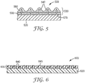
- Magnetizable abrasive particles according to the present disclosure may have various different basic configurations shown in FIGS. 1-3 , for example.
- magnetizable abrasive particle 100 comprises precisely-shaped ceramic body 110 and magnetizable layer 120.
- Magnetizable layer 120 preferably comprises magnetizable particles 125 retained in a binder matrix 130 (also referred to simply as "binder").
- Ceramic body 110 has two opposed major surfaces 160, 162 connected to each other by three side surfaces 140a, 140b, 140c.
- Magnetizable layer 120 is disposed on side surface 140a of ceramic body 110.
- the magnetizable layer may optionally extend somewhat onto other surfaces of the shaped ceramic abrasive body, but does not extend to cover a majority of any other surface of the shaped ceramic body.
- magnetizable layer 120 is coextensive with side surface 140a.
- magnetizable abrasive particles of this type can be preferentially aligned with the magnetizable layer-coated surface parallel to magnetic field lines of force.
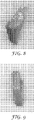
- magnetizable abrasive particle 200 comprises precisely-shaped ceramic body 110 and magnetizable layer 220.
- Magnetizable layer 220 preferably comprises magnetizable particles 125 (see FIG. 1A ) retained in binder matrix 130 (see FIG. 1A ).
- Ceramic body 110 has two opposed major surfaces 160, 162 connected to each other by three side surfaces 140a, 140b, 140c.
- Magnetizable layer 220 is disposed on major surface 160 of ceramic body 110.
- the magnetizable layer may optionally extend somewhat onto other surfaces of the shaped ceramic abrasive body, but does not extend to cover a majority of any other surface of the shaped ceramic body.
- magnetizable layer 220 is coextensive with major surface 160.
- magnetizable abrasive particles of this type preferentially align with the magnetic field lines of force resulting in an upright orientation of the magnetizable abrasive particles, when disposed centrally near the magnet (i.e., away to from field curvature at the magnet edges).
- magnetizable abrasive particle 300 comprises shaped ceramic abrasive body 310 and magnetizable layer 320.
- Magnetizable layer 320 preferably comprises magnetizable particles 125 (see FIG. 1A ) retained in binder matrix 130 (see FIG. 1A ).
- Ceramic body 310 is rod-shaped.
- Magnetizable layer 320 is disposed on end surface 350 of ceramic body 310.
- the magnetizable layer may optionally extend somewhat onto side surface 340 of shaped ceramic body 310, but does not extend to cover a majority of any other surface of the shaped ceramic body.
- magnetizable layer 320 is coextensive with end surface 350.
- magnetizable abrasive particles of this type preferentially align their longitudinal axes along the magnetic field lines of force resulting in the longitudinal axes of respective magnetizable abrasive particles being oriented.
- orientation of the magnetic field lines tends to be different at the center and edge of a magnet it is also possible to create various desired orientations of the magnetizable abrasive particles during their inclusion into an abrasive article.
- the magnetizable layer may be a unitary magnetizable material, or it may comprise magnetizable particles in a binder matrix.
- Suitable binders may be vitreous or organic, for example, as described for the binder matrix 130 hereinbelow.
- the binder matrix may be, for example selected from those vitreous and organic binders listed hereinabove, for example.
- the ceramic body may comprise any ceramic material (preferably a ceramic abrasive material), for example, selected from among the ceramic (i.e., not including diamond) abrasive materials listed hereinbelow.
- the magnetizable layer may be disposed on the ceramic body by any suitable method such as, for example, dip coating, spraying, painting, physical vapor deposition, and powder coating.
- the magnetizable layer is preferably essentially free of (i.e., containing less than 5 weight percent of, preferably containing less than 1 weight percent of) ceramic abrasive materials used in the ceramic body.
- the magnetizable layer may consist essentially of magnetizable materials (e.g., >99 to 100 percent by weight of vapor coated metals and alloys thereof), or it may contain magnetic particles retained in a binder matrix.
- the binder matrix of the magnetizable layer if present, can be inorganic (e.g., vitreous) or organic resin-based, and is typically formed from a respective binder precursor.
- Magnetizable abrasive particles according to the present disclosure can be prepared, for example, by applying a magnetizable layer or precursor thereof to the ceramic body.
- Magnetizable layers may be provided by physical vapor deposition as discussed hereinbelow.
- Magnetizable layer precursors may be provided as a dispersion or slurry in a liquid vehicle.
- the dispersion or slurry vehicle and can be made by simple mixing of its components (e.g., magnetizable particles, optional binder precursor, and liquid vehicle), for example.
- Exemplary liquid vehicles include water, alcohols (e.g., methanol, ethanol, propanol, butanol, ethylene glycol monomethyl ether), ethers (e.g., glyme, diglyme), and combinations thereof.
- the dispersion or slurry may contain additional components such as, for example, dispersant, surfactant, mold release agent, colorant, defoamer, and rheology modifier.
- additional components such as, for example, dispersant, surfactant, mold release agent, colorant, defoamer, and rheology modifier.
- the magnetizable layer precursor is dried to remove most or all of the liquid vehicle, although this is not a requirement. If a curable binder precursor is used, then a curing step (e.g., heating and/or exposure to actinic radiation) generally follows to provide the magnetizable layer.
- Vitreous binder may be produced from a precursor composition comprising a mixture or combination of one or more raw materials that when heated to a high temperature melt and/or fuse to form an integral vitreous binder matrix.
- the vitreous binder may be formed, for example, from frit.
- a frit is a composition that has been pre-fired before its use as a vitreous binder precursor composition for forming the vitreous binder of the magnetizable abrasive particle.
- frit is a generic term for a material that is formed by thoroughly blending a mixture comprising one or more frit forming components, followed by heating (also referred to as pre-firing) the mixture to a temperature at least high enough to melt it; cooling the resulting glass, and crushing it. The crushed material can then be screened to a very fine powder.
- suitable glasses for the vitreous binder and the frit for making it include silica glass, silicate glass, borosilicate glass, and combinations thereof.
- a silica glass is typically composed of 100 percent by weight of silica.
- the vitreous binder is a glass that include metal oxides or oxides of metalloids, for example, aluminum oxide, silicon oxide, boron oxide, magnesium oxide, sodium oxide, manganese oxide, zinc oxide, calcium oxide, barium oxide, lithium oxide, potassium oxide, titanium oxide, metal oxides that can be characterized as pigments (e.g., cobalt oxide, chromium oxide, and iron oxide), and mixtures thereof.
- suitable ranges for the vitreous binder and/or vitreous binder precursor include, based on the total weight of the vitreous binder and/or vitreous binder precursor: 25 to 90% by weight, preferably 35 to 85% by weight of SiO 2 ; 0 to 40% by weight, preferably 0 to 30% by weight, of B 2 O 3 ; 0 to 40% by weight, preferably 5 to 30% by weight, of Al 2 O 3 ; 0 to 5% by weight, preferably 0 to 3% by weight, of Fe 2 O 3 ; 0 to 5% by weight, preferably 0 to 3% by weight, of TiO 2 ; 0 to 20% by weight, preferably 0 to 10% by weight, of CaO; 0 to 20% by weight, preferably 1 to 10% by weight, of MgO; 0 to 20% by weight, preferably 0 to 10% by weight, of K 2 O; 0 to 25% by weight, preferably 0 to 15% by weight, of Na 2 O; 0 to 20% by weight, preferably 0 to 0
- An example of a suitable silicate glass composition comprises about 70 to about 80 percent by weight of silica, about 10 to about 20 percent sodium oxide, about 5 to about 10 percent calcium oxide, about 0.5 to about 1 percent aluminum oxide, about 2 to about 5 percent magnesium oxide, and about 0.5 to about 1 percent potassium oxide, based on the total weight of the glass frit
- Another example of a suitable silicate glass composition includes about 73 percent by weight of silica, about 16 percent by weight of sodium oxide, about 5 percent by weight of calcium oxide, about 1 percent by weight of aluminum oxide, about 4 percent by weight of magnesium oxide, and about 1 percent by weight of potassium oxide, based on the total weight of the glass frit.
- the glass matrix comprises an alumina-borosilicate glass comprising SiO 2 , B 2 O 3 , and Al 2 O 3 .
- An example of a suitable borosilicate glass composition comprises about 50 to about 80 percent by weight of silica, about 10 to about 30 percent by weight of boron oxide, about 1 to about 2 percent by weight of aluminum oxide, about 0 to about 10 percent by weight of magnesium oxide, about 0 to about 3 percent by weight of zinc oxide, about 0 to about 2 percent by weight of calcium oxide, about 1 to about 5 percent by weight of sodium oxide, about 0 to about 2 percent by weight of potassium oxide, and about 0 to about 2 percent by weight of lithium oxide, based on the total weight of the glass frit.
- borosilicate glass composition includes about 52 percent by weight of silica, about 27 percent by weight of boron oxide, about 9 percent by weight of aluminum oxide, about 8 percent by weight of magnesium oxide, about 2 percent by weight of zinc oxide, about 1 percent by weight of calcium oxide, about 1 percent by weight of sodium oxide, about 1 percent by weight of potassium oxide, and about 1 percent by weight of lithium oxide, based on the total weight of the glass frit.
- suitable borosilicate glass composition include, based upon weight, 47.61% SiO 2 , 16.65% Al 2 O 3 , 0.38% Fe 2 O 3 , 0.35% TiO 2 , 1.58% CaO, 0.10% MgO, 9.63% Na 2 O, 2.86% K 2 O, 1.77% Li 2 O, 19.03% B 2 O 3 , 0.02% MnO 2 , and 0.22% P 2 O 5 ; and 63% SiO 2 , 12% Al 2 O 3 , 1.2%CaO, 6.3% Na 2 O, 7.5%K 2 O, and 10% B 2 O 3 .
- a useful alumina-borosilicate glass composition comprises, by weight, about 18% B 2 O 3 , 8.5% Al 2 O 3 , 2.8%BaO, 1.1% CaO, 2.1%Na 2 O, 1.0% Li 2 O, with the balance being SiO 2 .
- Such an alumina-borosilicate glass, having a particle size of less than about 45 mm, is commercially available from Specialty Glass Incorporated, Oldsmar, Florida.
- Glass frit for making glass-ceramics may be selected from the group consisting of magnesium aluminosilicate, lithium aluminosilicate, zinc aluminosilicate, calcium aluminosilicate, and combinations thereof.
- Known crystalline ceramic phases that can form glasses within the above listed systems include: cordierite (2MgO.2Al 2 O 3 .5SiO 2 ), gehlenite (2CaO.Al 2 O 3. SiO 2 ), anorthite (2CaO.Al 2 O 3.
- Glass frit for making glass-ceramic may comprise nucleating agents. Nucleating agents are known to facilitate the formation of crystalline ceramic phases in glass-ceramics. As a result of specific processing techniques, glassy materials do not have the long range order that crystalline ceramics have. Glass-ceramics are the result of controlled heat-treatment to produce, in some cases, over 90% crystalline phase or phases with the remaining non-crystalline phase filling the grain boundaries. Glass ceramics combine the advantage of both ceramics and glasses and offer durable mechanical and physical properties.
- Frit useful for forming vitreous binder may also contain frit binders (e.g., feldspar, borax, quartz, soda ash, zinc oxide, whiting, antimony trioxide, titanium dioxide, sodium silicofluoride, flint, cryolite, boric acid, and combinations thereof) and other minerals (e.g., clay, kaolin, wollastonite, limestone, dolomite, chalk, and combinations thereof).
- frit binders e.g., feldspar, borax, quartz, soda ash, zinc oxide, whiting, antimony trioxide, titanium dioxide, sodium silicofluoride, flint, cryolite, boric acid, and combinations thereof
- other minerals e.g., clay, kaolin, wollastonite, limestone, dolomite, chalk, and combinations thereof.
- Vitreous binder in the magnetizable abrasive particles may be selected, for example, based on a desired coefficient of thermal expansion (CTE). Generally, it is useful for the vitreous binder and abrasive particles to have similar CTEs, for example, ⁇ 100%, 50% 40%, 25%, or 20% of each other.
- the CTE of fused alumina is typically about 8 x 10 -6 /Kelvin (K).
- K Kelvin
- a vitreous binder may be selected to have a CTE in a range from 4 x 10 -6 /K to 16 x 10 -6 /K.
- An example of a glass frit for making a suitable vitreous binder is commercially available, for example, as F245 from Fusion Ceramics, Carrollton, Ohio.
- the vitreous binder precursor in a powder form, may be mixed with a temporary binder, typically an organic binder (e.g., starch, sucrose, mannitol), which burns out during firing of the vitreous binder precursor.
- a temporary binder typically an organic binder (e.g., starch, sucrose, mannitol), which burns out during firing of the vitreous binder precursor. Firing/sintering of vitreous binders can be done, for example, in a kiln or tube furnace using techniques known in the art.
- Organic binders are generally prepared by curing (i.e., crosslinking) a resinous organic binder precursor.
- suitable organic binder precursors include thermally-curable resins and radiation-curable resins, which may be cured, for example, thermally and/or by exposure to radiation.
- Exemplary organic binder precursors include glues, phenolic resins, aminoplast resins, urea-formaldehyde resins, melamine-formaldehyde resins, urethane resins, acrylic resins (e.g., aminoplast resins having pendant ⁇ , ⁇ -unsaturated groups, acrylated urethanes, acrylated epoxy resins, acrylated isocyanurates), acrylic monomer/oligomer resins, epoxy resins (including bismaleimide and fluorene-modified epoxy resins), isocyanurate resins, an combinations thereof.
- Curatives such as thermal initiators, catalysts, photoinitiators, hardeners, and the like may be added to the organic binder precursor, typically selected and in an effective amount according to the resin system chosen.
- Conditions for curing organic binder precursors may include heating in an oven or with infrared radiation and/or actinic radiation (e.g., in the case of photoinitiated cure) using techniques known in the art.
- the magnetizable layer may be deposited using a vapor deposition technique such as, for example, physical vapor deposition (PVD) including magnetron sputtering.
- PVD physical vapor deposition
- PVD metallization of various metals, metal oxides and metallic alloys is disclosed in, for example, U. S. Pat Nos. 4,612,242 (Vesley ) and 7,727,931 (Brey et al. ).
- Magnetizable layers can typically be prepared in this general manner, but care should be generally taken to prevent the vapor coating from covering the entire surface of the shaped ceramic body. The may be accomplished by masking a portion of the ceramic body to prevent vapor deposition.
- metallic materials that may be vapor coated include stainless steels, nickel, cobalt.
- Exemplary useful magnetizable particles/materials may comprise: iron; cobalt; nickel; various alloys of nickel and iron marketed as Permalloy in various grades; various alloys of iron, nickel and cobalt marketed as Fernico, Kovar, FerNiCo I, or FerNiCo II; various alloys of iron, aluminum, nickel, cobalt, and sometimes also copper and/or titanium marketed as Alnico in various grades; alloys of iron, silicon, and aluminum (typically about 85:9:6 by weight) marketed as Sendust alloy; Heusler alloys (e.g., Cu 2 MnSn); manganese bismuthide (also known as Bismanol); rare earth magnetizable materials such as gadolinium, dysprosium, holmium, europium oxide, and alloys of samarium and cobalt (e.g., SmCo 5 ); MnSb; ferrites such as
- the magnetizable material comprises at least one metal selected from iron, nickel, and cobalt, an alloy of two or more such metals, or an alloy of at one such metal with at least one element selected from phosphorus and manganese.
- the magnetizable material is an alloy containing 8 to 12 weight percent (wt %) aluminum, 15 to 26 wt. % nickel, 5 to 24 wt. % cobalt, up to 6 wt. % copper, up to 1 wt.% titanium, wherein the balance of material to add up to 100 wt % is iron. Alloys of this type are available under the trade designation "ALNICO".
- Useful abrasive materials that can be used as ceramic bodies include, for example, fused aluminum oxide, heat treated aluminum oxide, white fused aluminum oxide, ceramic aluminum oxide materials such as those commercially available as 3M CERAMIC ABRASIVE GRAIN from 3M Company of St Paul, Minnesota, black silicon carbide, green silicon carbide, titanium diboride, boron carbide, tungsten carbide, titanium carbide, cubic boron nitride, garnet, fused alumina zirconia, sol-gel derived ceramics (e.g., alumina ceramics doped with chromia, ceria, zirconia, titania, silica, and/or tin oxide), silica (e.g., quartz, glass beads, glass bubbles and glass fibers), feldspar, or flint.
- fused aluminum oxide heat treated aluminum oxide
- white fused aluminum oxide ceramic aluminum oxide materials
- ceramic aluminum oxide materials such as those commercially available as 3M CERAMIC ABRASIVE GRAIN from
- sol-gel derived crushed ceramic particles can be found in U. S. Pat Nos. 4,314,827 (Leitheiser et al. ), 4,623,364 (Cottringer et al. ); 4,744,802 (Schwabel ), 4,770,671 (Monroe et al. ); and 4,881,951 (Monroe et al. ).
- the ceramic bodies have a Mohs hardness of at least 6, preferably at least 7, or even at least 8.
- the ceramic body may be shaped (e.g., precisely-shaped) or random (e.g., crushed). Shaped abrasive particles and precisely-shaped ceramic bodies may be prepared by a molding process using sol-gel technology as described in U. S. Pat. Nos. 5,201,916 (Berg ); 5,366,523 (Rowenhorst ( Re 35,570 )); and 5,984,988 (Berg ).
- U. S. Pat No. 8,034,137 (Erickson et al. ) describes alumina particles that have been formed in a specific shape, then crushed to form shards that retain a portion of their original shape features.
- the ceramic bodies are precisely-shaped (i.e., the ceramic bodies have shapes that are at least partially determined by the shapes of cavities in a production tool used to make them).
- Exemplary shapes of ceramic bodies include crushed, pyramids (e.g., 3-, 4-, 5-, or 6-sided pyramids), truncated pyramids (e.g., 3-, 4-, 5-, or 6-sided truncated pyramids), cones, truncated cones, rods (e.g., cylindrical, vermiform), and prisms (e.g., 3-, 4-, 5-, or 6-sided prisms).
- pyramids e.g., 3-, 4-, 5-, or 6-sided pyramids
- truncated pyramids e.g., 3-, 4-, 5-, or 6-sided truncated pyramids
- cones e.g., truncated cones
- rods e.g., cylindrical, vermiform
- prisms e.g., 3-, 4-, 5-, or 6-sided prisms
- Exemplary magnetizable materials that may be suitable for use in magnetizable particles may comprise: iron; cobalt; nickel; various alloys of nickel and iron marketed as Permalloy in various grades; various alloys of iron, nickel and cobalt marketed as Fernico, Kovar, FerNiCo I, or FerNiCo II; various alloys of iron, aluminum, nickel, cobalt, and sometimes also copper and/or titanium marketed as Alnico in various grades; alloys of iron, silicon, and aluminum (typically about 85:9:6 by weight) marketed as Sendust alloy; Heusler alloys (e.g., Cu 2 MnSn); manganese bismuthide (also known as Bismanol); rare earth magnetizable materials such as gadolinium, dysprosium, holmium, europium oxide, alloys of neodymium, iron and boron (e.g., Nd 2 Fe 14 B), and alloys of samarium and cobalt (e.g., S
- the magnetizable material comprises at least one metal selected from iron, nickel, and cobalt, an alloy of two or more such metals, or an alloy of at one such metal with at least one element selected from phosphorus and manganese.
- the magnetizable material is an alloy (e.g., Alnico alloy) containing 8 to 12 weight percent (wt %) aluminum, 15 to 26 wt % nickel, 5 to 24 wt. % cobalt, up to 6 wt % copper, up to 1 wt. % titanium, wherein the balance of material to add up to 100 wt % is iron.
- the magnetizable particles may have any size, but are preferably much smaller than the ceramic bodies as judged by average particle diameter, preferably 4 to 2000 times smaller, more preferably 100 to 2000 times smaller, and even more preferably 500 to 2000 times smaller, although other sizes may also be used.
- the magnetizable particles may have a Mohs hardness of 6 or less (e.g., 5 or less, or 4 or less), although this is not a requirement.
- Magnetizable abrasive particles according to the present disclosure may be independently sized according to an abrasives industry recognized specified nominal grade.
- Exemplary abrasive industry recognized grading standards include those promulgated by ANSI (American National Standards Institute), FEPA (Federation of European Producers of Abrasives), and JIS (Japanese Industrial Standard).
- ANSI grade designations include, for example: ANSI 4, ANSI 6, ANSI 8, ANSI 16, ANSI 24, ANSI 36, ANSI 46, ANSI 54, ANSI 60, ANSI 70, ANSI 80, ANSI 90, ANSI 100, ANSI 120, ANSI 150, ANSI 180, ANSI 220, ANSI 240, ANSI 280, ANSI 320, ANSI 360, ANSI 400, and ANSI 600.
- FEPA grade designations include F4, F5, F6, F7, F8, F10, F12, F14, F16, F18, F20, F22, F24, F30, F36, F40, F46, F54, F60, F70, F80, F90, F100, F120, F150, F180, F220, F230, F240, F280, F320, F360, F400, F500, F600, F800, F1000, F1200, F1500, and F2000.
- JIS grade designations include JIS8, JIS12, JIS16, JIS24, JIS36, JIS46, JIS54, JIS60, JIS80, JIS100, JIS150, JIS180, JIS220, JIS240, JIS280, JIS320, JIS360, JIS400, JIS600, JIS800, JIS1000, JIS1500, JIS2500, JIS4000, JIS6000, JIS8000, and JIS10,000.
- the magnetizable abrasive particles can be graded to a nominal screened grade using U. S. A. Standard Test Sieves conforming to ASTM E-11 "Standard Specification for Wire Cloth and Sieves for Testing Purposes".
- ASTM E-11 prescribes the requirements for the design and construction of testing sieves using a medium of woven wire cloth mounted in a frame for the classification of materials according to a designated particle size.
- a typical designation may be represented as -18+20 meaning that the magnetizable abrasive particles pass through a test sieve meeting ASTM E-11 specifications for the number 18 sieve and are retained on a test sieve meeting ASTM E-11 specifications for the number 20 sieve.
- the magnetizable abrasive particles have a particle size such that most of the particles pass through an 18 mesh test sieve and can be retained on a 20, 25, 30, 35, 40, 45, or 50 mesh test sieve.
- the magnetizable abrasive particles can have a nominal screened grade of: -18+20, -20/+25, -25+30, -30+35, -35+40, -40+45, -45+50, -50+60, -60+70, -70/+80, -80+100, -100+120, -120+140, -140+170, -170+200, -200+230, -230+270, -270+325, -325+400, -400+450, -450+500, or -500+635.
- a custom mesh size can be used such as -90+100.
- one or more magnets and/or electromagnets generating a magnetic field can optionally be used to place and/or orient the magnetizable abrasive particles prior to curing the binder (e.g., vitreous or organic) precursor to produce the abrasive article.
- the magnetic field may be substantially uniform over the magnetizable abrasive particles before they are fixed in position in the binder or continuous over the entire, or it may be uneven, or even effectively separated into discrete sections.
- the orientation of the magnetic field is configured to achieve alignment of the magnetizable abrasive particles according to a predetermined orientation.
- magnetic field may be used to urge the magnetizable abrasive particles onto the make layer precursor (i.e., the binder precursor for the make layer) of a coated abrasive article while maintaining a vertical or inclined orientation relative to a horizontal backing.
- the magnetizable abrasive particles are fixed in their placement and orientation.
- the presence or absence of strong magnetic field can be used to selectively placed the magnetizable abrasive particles onto the make layer precursor.
- An analogous process may be used for manufacture of slurry coated abrasive articles, except that the magnetic field acts on the magnetizable particles within the slurry. The above processes may also be carried out on nonwoven backings to make nonwoven abrasive articles.
- the magnetizable abrasive particles can be positioned and/or oriented within the corresponding binder precursor, which is then pressed and cured.
- Magnetizable abrasive particles can be used in loose form (e.g., free-flowing or in a slurry) or they may be incorporated into various abrasive articles (e.g., coated abrasive articles, bonded abrasive articles, nonwoven abrasive articles, and/or abrasive brushes).
- abrasive articles e.g., coated abrasive articles, bonded abrasive articles, nonwoven abrasive articles, and/or abrasive brushes.
- Magnetizable abrasive particles are useful, for example, in the construction of abrasive articles, including for example, coated abrasive articles (for example, conventional make and size coated abrasive articles, slurry coated abrasive articles, and structured abrasive articles), abrasive brushes, nonwoven abrasive articles, and bonded abrasive articles such as grinding wheels, hones and whetstones.
- coated abrasive articles for example, conventional make and size coated abrasive articles, slurry coated abrasive articles, and structured abrasive articles
- abrasive brushes for example, nonwoven abrasive articles, and bonded abrasive articles such as grinding wheels, hones and whetstones.
- FIG. 4 shows an exemplary embodiment of a Type 27 depressed-center grinding wheel 400 (i.e., an embodiment of a bonded abrasive article) according to one embodiment of the present disclosure.
- Center hole 412 is used for attaching bonded abrasive wheel 400 to, for example, a power driven tool (not shown).
- Bonded abrasive wheel 400 comprises shaped ceramic abrasive particles 420 according to the present disclosure retained in binder 425.
- suitable binders 425 include: organic binders such as epoxy binders, phenolic binders, aminoplast binders, and acrylic binders; and inorganic binders such as vitreous binders. Further details concerning suitable organic and inorganic binders can be found hereinabove in the discussion of binder matrixes in the magnetizable layer.
- the abrasive coat may comprise a make coat, a size coat, and magnetizable abrasive particles.
- exemplary coated abrasive article 500 has backing 520 and abrasive layer 530.
- Abrasive layer 530 includes magnetizable abrasive particles 540 according to the present disclosure secured to backing 520 by make layer 550 and size layer 560, each comprising a respective binder (e.g., epoxy resin, urethane resin, phenolic resin, aminoplast resin, or acrylic resin) that may be the same or different.
- a respective binder e.g., epoxy resin, urethane resin, phenolic resin, aminoplast resin, or acrylic resin
- the abrasive coat may comprise a cured slurry comprising a curable binder precursor and magnetizable abrasive particles according to the present disclosure.
- exemplary coated abrasive article 600 has backing 620 and abrasive layer 630.
- Abrasive layer 630 includes magnetizable abrasive particles 640 and a binder 645 (e.g., epoxy resin, urethane resin, phenolic resin, aminoplast resin, acrylic resin).
- Nonwoven abrasive articles typically include a porous (e.g., a lofty open porous) polymer filament structure having magnetizable abrasive particles bonded thereto by a binder.
- a porous (e.g., a lofty open porous) polymer filament structure having magnetizable abrasive particles bonded thereto by a binder An exemplary embodiment of a nonwoven abrasive article according to the present invention is shown in FIGS. 7A and 7B .
- Nonwoven abrasive article 700 includes a lofty open low-density fibrous web formed of entangled filaments 710 impregnated with binder 720 (e.g., epoxy resin, urethane resin, phenolic resin, aminoplast resin, acrylic resin).
- binder 720 e.g., epoxy resin, urethane resin, phenolic resin, aminoplast resin, acrylic resin.
- Binder 720 coats portions of filaments 710 and forms globules 750, which may encircle individual filaments or bundles of filaments that adhere to the surface of the filament and/or collect at the intersection of contacting filaments, providing abrasive sites throughout the nonwoven abrasive article.
- Abrasive articles according to the present disclosure are useful for abrading a workpiece.
- Methods of abrading range from snagging (i.e., high pressure high stock removal) to polishing (e.g., polishing medical implants with coated abrasive belts), wherein the latter is typically done with finer grades of abrasive particles.
- One such method includes the step of frictionally contacting an abrasive article (e.g., a coated abrasive article, a nonwoven abrasive article, or a bonded abrasive article) with a surface of the workpiece, and moving at least one of the abrasive article or the workpiece relative to the other to abrade at least a portion of the surface.
- an abrasive article e.g., a coated abrasive article, a nonwoven abrasive article, or a bonded abrasive article
- workpiece materials include metal, metal alloys, exotic metal alloys, ceramics, glass, wood, wood-like materials, composites, painted surfaces, plastics, reinforced plastics, stone, and/or combinations thereof.
- the workpiece may be flat or have a shape or contour associated with it.
- Exemplary workpieces include metal components, plastic components, particleboard, camshafts, crankshafts, furniture, and turbine blades.
- the applied force during abrading typically ranges from about 1 kilogram to about 100 kilograms.
- Abrasive articles according to the present disclosure may be used by hand and/or used in combination with a machine. At least one of the abrasive article and the workpiece is moved relative to the other when abrading. Abrading may be conducted under wet or dry conditions. Exemplary liquids for wet abrading include water, water containing conventional rust inhibiting compounds, lubricant, oil, soap, and cutting fluid. The liquid may also contain defoamers, degreasers, for example.
- the present disclosure provides a magnetizable abrasive particle comprising a ceramic body having an outer surface, and a magnetizable layer disposed on a portion, but not the entirety, of the outer surface.
- the present disclosure provides a magnetizable abrasive particle according to the first embodiment, wherein the ceramic body comprises a shaped ceramic body.
- the present disclosure provides a magnetizable abrasive particle according to the second embodiment, wherein the shaped ceramic body comprises a precisely-shaped ceramic body.
- the present disclosure provides a magnetizable abrasive particle according to any one of the first to third embodiments, wherein the outer surface of the ceramic body comprises a plurality of facets.
- the present disclosure provides a magnetizable abrasive particle according to the fourth embodiment, wherein the magnetizable layer completely covers a single facet.
- the present disclosure provides a magnetizable abrasive particle according to the fourth embodiment, wherein none of the facets is completely covered by the magnetizable layer.
- the present disclosure provides a magnetizable abrasive particle according to any one of the first to sixth embodiment, wherein the ceramic body comprises a platelet having two opposed major facets connected to each other by a plurality of side facets.
- the present disclosure provides a magnetizable abrasive particle according to the seventh embodiment, wherein the platelet is triangular.
- the present disclosure provides a magnetizable abrasive particle according to the seventh or eighth embodiment, wherein the magnetizable layer completely covers one of the two opposed major facets.
- the present disclosure provides a magnetizable abrasive particle according to the seventh or eighth embodiment, wherein the magnetizable layer completely covers one of the side facets.
- the present disclosure provides a magnetizable abrasive particle according to the ninth embodiment, wherein the magnetizable layer has a magnetizable dipole oriented perpendicular to the facet which it completely covers.
- the present disclosure provides a magnetizable abrasive particle according to the ninth embodiment, wherein the magnetizable layer has a magnetic dipole oriented parallel to the facet which it completely covers.
- the present disclosure provides a magnetizable abrasive particle according to any one of the first to sixth embodiments, wherein the ceramic body comprises a rod.
- the present disclosure provides a magnetizable abrasive particle according to any one of the first to thirteenth embodiments, wherein the magnetizable layer comprises magnetizable particles disposed in a binder matrix.
- the present disclosure provides a magnetizable abrasive particle according to the thirteenth or fourteenth embodiment, wherein the binder matrix comprises an organic binder matrix.
- the present disclosure provides an abrasive article comprising a plurality of magnetizable abrasive particles according to any one of the first to fifteenth embodiments.
- the present disclosure provides an abrasive article comprising a plurality of magnetizable abrasive particles according to the sixteenth embodiment retained in a binder material.
- the present disclosure provides an abrasive article according to the seventeenth embodiment, wherein the abrasive article comprises a bonded abrasive wheel.
- the present disclosure provides an abrasive article according to the seventeenth embodiment, wherein the coated abrasive article comprises an abrasive layer disposed on a backing, and wherein the abrasive layer comprises the binder material and the plurality of magnetizable abrasive particles.
- the present disclosure provides an abrasive article according to the seventeenth embodiment, wherein the abrasive article comprises a nonwoven abrasive, wherein the nonwoven abrasive comprises a lofty open nonwoven fiber web having an abrasive layer disposed on at least a portion thereof, and wherein the abrasive layer comprises the binder material and the plurality of magnetizable abrasive particles.
- the present disclosure provides an abrasive article according to the nineteenth embodiment, wherein a majority of the magnetizable abrasive particles are aligned parallel to each other.
- CM Silane Treated Calcium Metasilicate obtained as 400 WOLLASTOCOAT from NYCO Minerals Inc., Willsboro, New York.
- CRY Cryolite obtained as CRYOLITE TYPE RTN-C from Koppers Trading, Pittsburgh, Pennsylvania.
- IO Red iron oxide pigment MP Magnetic primer obtained as MAGNETIC PRIMER MAGNETIC GRAY from Krylon, Cleveland, Ohio.
- SAP Shaped abrasive particles were prepared according to the disclosure of U. S. Pat No. 8,142,531 (Adefris et al ).
- the shaped abrasive particles were prepared by molding alumina sol gel in equilateral triangle-shaped polypropylene mold cavities. After drying and firing, the resulting shaped abrasive particles, which were shaped as truncated triangular pyramids, were about 1.4 mm (side length) ⁇ 0.35 mm (thickness), with a draft angle approximately 98 degrees.
- the shaped abrasive particles were then coated with inorganic material according to the method described in U. S. Pat. No. 5,213,591 (Celikkaya et al ).
- SAP was placed in a polypropylene tool as described in Example 1 of PCT Pat. Publ. No. WO 2015/100018 A1 (Culler et al. ), so that each of the abrasive particles resided in a respective triangular cavity of the tool with a tip pointing down and with the opposite sidewall exposed outside the cavity.
- the MP spray can was shaken for several minutes prior to use. While the abrasive mineral housed in the tool, the MP spray can was pointed down onto the tool and sprayed for about 4 seconds. After the spraying was done, the coated mineral was allowed to sit for 30 minutes to dry off any solvent After drying, the coated abrasive particles were dislodged from the tool.
- Each of the resultant magnetized abrasive particles had a magnetic layer on the surface of an edge (sidewall) of the shaped abrasive particle, with a small amount continuing onto adjacent surfaces as shown in FIG. 8 .
- a sheet of paper was placed over the upper surface of the magnet
- the individual magnetic shaped abrasive particles were oriented upright with the coated edge facing upwards (as shown as FIG. 8 ) but inclined due to the weight of the abrasive particle, which was supported along a substantially uncoated side wall.
- SAP was placed in a polypropylene tool as described in EXAMPLE 1, while the abrasive mineral was housed in the tool.
- the tool was placed on the 6 inch (15.2 cm) ⁇ 0.5 inch (1.27 cm) end surface of the rare earth magnet used in Example 1.
- the tool was oriented such that the opposed major surface faces of the minerals were aligned parallel to the magnetic field lines where the tool was placed (i.e., the length of the exposed sidewall of the SAP particle was parallel to the thickness of the magnet).
- the MP spray can was shaken for several minutes prior to use. While the abrasive mineral housed in the tool, the MP spray can was pointed down onto the tool and sprayed for about 4 seconds.
- each of the resultant magnetizable abrasive particles had a magnetizable coating on the surface of an edge (sidewall) of the shaped abrasive particle (shown in FIG. 10 ).
- Example 2 was repeated except that the tool was rotated 90° so that the magnetic field was oriented such that the opposed major surface faces of the minerals were aligned perpendicular to the magnetic field lines where the tool was placed (i.e., the thickness of the exposed sidewall of the SAP particle was parallel to the thickness of the magnet).
- Each of the resultant magnetizable abrasive particles had a magnetizable coating on the surface of an edge (sidewall) of the shaped abrasive particle (shown in FIG. 11 ).
- Example 2 The response of resultant magnetizable shaped abrasive particles from Examples 2 and 3 to an applied magnetic field was tested by placing the individual abrasive minerals on a horizontal piece of paper which was placed onto the 6 inches (15.24 cm) ⁇ 3 inches (7.62 cm) surface of the rare earth magnet used in Example 1.
- magnetizable shaped abrasive particles from Examples 2 and 3 were placed at the edge of the magnet surface.
- the piece of paper holding the magnetic shaped abrasive particles was agitated slightly.
- the magnetic shaped abrasive particles were oriented upright (shown as FIG. 12 ) with the magnetic layer contacting the paper.
- FIG. 12 the left magnetizable shaped abrasive particle was from Example 3 and the right magnetizable shaped abrasive particle was from Example 2.
- No magnetic field was applied.
- MP spray can was shaken for several minutes prior to use. While the abrasive mineral was housed in the tool, the MP spray can was pointed down onto the tool and sprayed for about 4 seconds. After the spraying was done, the coated magnetic shaped abrasive mineral was allowed to sit for 30 minutes to dry off any solvent After drying, the coated abrasive particles were dislodged from the tool.
- Each of the resultant magnetic shaped abrasive particles had a magnetic coating on the largest triangular major surface of the shaped abrasive particle as shown in FIGS. 13A and 13B .
- resultant abrasive particles to magnetic field was tested by placing the individual abrasive minerals on a piece of paper which was placed on a horizontal 6 inch (15.24 cm) ⁇ 3 inch (7.62 cm) surface of the rare earth magnet used in Example 1. Two locations on the magnet were selected. When resultant magnetic shaped abrasive particles were placed on the center of the magnet where the magnetic field goes directly upwards from the magnet, the individual abrasive minerals were oriented upright with an edge facing down on the paper (as shown as FIG. 13A ).
- SAP was placed in a polypropylene tool as described in EXAMPLE 4. While the abrasive mineral housed in the tool, the tool was placed on the top of the 6 inch (15.24 cm) ⁇ 3 inch (7.62 cm) surface of the rare earth magnet used in Example 1, such that the magnetic field lines were perpendicular to the tool.
- the MP spray can was shaken for several minutes prior to use. While the abrasive mineral housed in the tool, the MP spray can was pointed down onto the tool and sprayed for about 4 seconds. After the spraying was done, the coated mineral was allowed to sit for 30 minutes to dry off any solvent. After drying, the coated abrasive particles were dislodged from the tool.
- Each of the resultant magnetic shaped abrasive particles had a magnetic coating on one major surface of the shaped abrasive particle as shown in FIGS. 14A and 14B .
- resultant abrasive particles to magnetic field was tested by placing the individual abrasive minerals on a piece of paper which was placed on a horizontal 6 inches (15.24 cm) ⁇ 3 inches (7.62 cm) surface of the rare earth magnetic used in Example 1. Two locations on the magnet were selected. When resultant magnetic shaped abrasive particles were placed on the edge of the magnet where the magnetic field approached a parallel path from the magnet, the individual abrasive minerals were oriented upright with an edge facing down on the paper (as shown in FIG. 14A ). When resultant abrasive particles were placed on the center of the magnet where the magnetic field went directly upwards from the magnet, individual abrasive minerals were laid flat with the coated surface facing upward on the paper (as shown in FIG. 14B ).
- the coated 3-inch disc was then placed directly in the center of an 8-inch (20.3 cm) diameter x 2 inches (5.1 cm) thick rare earth neodymium disc magnet (grade N50, obtained from Supermagnetman, Pelham, Alabama) with an 8-inch diameter which was magnetized through its thickness (i.e., north and south poles on opposite surfaces separated by the thickness).
- Face-coated magnetic shaped abrasive particles according to EXAMPLE 4 were then dropped from a distance of 1 inch (2.54 cm) to uniformly cover the surface of the disc.
- the abrasive particles were added to a weight of 1.55 ⁇ 0.07 grams.
- the disc was given a make pre-cure at 90°C for 12 hours followed by 103°C for 1 hour.
- the pre-cured disc was then coated by brush with size resin consisting of 37.4 parts of PR, 58.8 parts of CRY, 1.8 parts of IO, and 2.0 parts of deionized water. Excess size resin was removed with a dry brush until the flooded glossy appearance was reduced to a matte appearance. The amount of size resin applied was 3.15 g ⁇ 0.06 grams. The disc was cured for 90 minutes at 90°C, followed by 16 hours at 103°C.
- Discs (3-inch (7.6-cm) diameter) made from EXAMPLES 6, 7, and COMPARATIVE EXAMPLE A were allowed to equilibrate with ambient humidity for 2 days before testing.
- a quick change attachment of the type described in U. S. Pat. No. 6,817,935 (Bates et al. ) was affixed to the center back of each disc using adhesive.
- the disc to be tested was attached to a back pad, obtained as ROLOC DISC PAD TR 45091 from 3M Company, which was mounted on an electric rotary tool.
- the rotary tool was disposed over an X-Y table having a 1018 carbon steel workpiece measuring 14 inches (35.56 cm) ⁇ 6 inches (15.24 cm) secured to the X-Y table.
- the rotary tool was then activated to rotate at 9000 rounds per minute.
- the abrasive article was then urged at an angle of 5 degrees against the bar at a load of 5 pounds (2.27 kilograms).
- the disc traversed across the 14 inches (35.56 cm) ⁇ 6 inches (15.24 cm) face of the workpiece for 20 passes at a rate of 4.7 inches/second (11.9 cm/second) as to not go over the same abraded area twice.
- the mass of the workpiece was measured before and after each cycle to determine the total mass loss in grams after each cycle. A cumulative mass loss was determined at the end of 4 cycles.
- Table 2 The test result for each example is shown in Table 2, below.
Landscapes
- Chemical & Material Sciences (AREA)
- Engineering & Computer Science (AREA)
- Ceramic Engineering (AREA)
- Organic Chemistry (AREA)
- Manufacturing & Machinery (AREA)
- Materials Engineering (AREA)
- Structural Engineering (AREA)
- Chemical Kinetics & Catalysis (AREA)
- Inorganic Chemistry (AREA)
- Medicinal Chemistry (AREA)
- Health & Medical Sciences (AREA)
- Polymers & Plastics (AREA)
- Composite Materials (AREA)
- Mechanical Engineering (AREA)
- General Chemical & Material Sciences (AREA)
- Dispersion Chemistry (AREA)
- Polishing Bodies And Polishing Tools (AREA)
Description
- The present disclosure broadly relates to abrasive particles, abrasive articles, and methods of making them.
- Various types of abrasive articles are known in the art. For example, coated abrasive articles generally have abrasive particles adhered to a backing by a resinous binder material. Examples include sandpaper and structured abrasives having precisely shaped abrasive composites adhered to a backing. The abrasive composites generally include abrasive particles and a resinous binder.
- Bonded abrasive particles include abrasive particles retained in a binder matrix that can be resinous or vitreous. Examples include, grindstones, cutoff wheels, hones, and whetstones.
- Precise placement and orientation of abrasive particles in abrasive articles such as, for example, coated abrasive articles and bonded abrasive articles has been a source of continuous interest for many years.
- For example, coated abrasive articles have been made using techniques such as electrostatic coating of abrasive particles have been used to align crushed abrasive particles with the longitudinal axes perpendicular to the backing. Likewise, shaped abrasive particles have been aligned by mechanical methods as disclosed in U. S. Pat. Appl. Publ. No.
2013/0344786 A1 (Keipert ). - Precise placement and orientation of abrasive particles in bonded abrasive articles has been described in the patent literature. For example,
U. S. Pat No. 1,930,788 (Buckner ) describes the use of magnetic flux to orient abrasive grain having a thin coating of iron dust in bonded abrasive articles. Likewise, British (GB) Pat No.396,231 (Buckner - U. S. Pat. Appl. Publ. No.
2008/0289262 A1 (Gao ) discloses equipment for making abrasive particles in even distribution, array pattern, and preferred orientation. Using electric current to form a magnetic field causing acicular soft magnetic metallic sticks to absorb or release abrasive particles plated with soft magnetic materials -
US 2016/144480 A1 ,US 2015/259587 A1 andEP 2,692,818 A1 all disclose abrasive particles that are at least partially coated with a magnetic material. - The present inventors have discovered that magnetizable abrasive particles with incomplete magnetizable layers according to the present disclosure can be manipulated using magnetic fields in ways that differ from abrasive particles having layers over their entire surface to provide various abrasive articles.
- In one aspect, the present disclosure provides a magnetizable abrasive particle comprising a ceramic body having an outer surface, and a magnetizable layer disposed on a portion, but not the entirety, of the outer surface.
- In another aspect, the present disclosure provides a plurality of magnetizable abrasive particles according to the present disclosure.
- In yet another aspect, the present disclosure provides a plurality of magnetizable abrasive particles according to the present disclosure retained in a binder material.
- As used herein:
The term "ceramic" refers to any of various hard, brittle, heat- and corrosion-resistant materials made of at least one metallic element (which may include silicon) combined with oxygen, carbon, nitrogen, or sulfur. Ceramics may be crystalline or polycrystalline, for example. - The term "ferrimagnetic" refers to materials (in bulk) that exhibit ferrimagnetism. Ferrimagnetism is a type of permanent magnetism that occurs in solids in which the magnetic fields associated with individual atoms spontaneously align themselves, some parallel, or in the same direction (as in ferromagnetism), and others generally antiparallel, or paired off in opposite directions (as in antifermmagnetism). The magnetic behavior of single crystals of ferrimagnetic materials may be attributed to the parallel alignment; the diluting effect of those atoms in the antiparallel arrangement keeps the magnetic strength of these materials generally less than that of purely ferromagnetic solids such as metallic iron. Ferrimagnetism occurs chiefly in magnetic oxides known as ferrites. The spontaneous alignment that produces ferrimagnetism is entirely disrupted above a temperature called the Curie point, characteristic of each ferrimagnetic material. When the temperature of the material is brought below the Curie point, ferrimagnetism revives.
- The term "ferromagnetic" refers to materials (in bulk) that exhibit ferromagnetism. Ferromagnetism is a physical phenomenon in which certain electrically uncharged materials strongly attract others. In contrast to other substances, ferromagnetic materials are magnetized easily, and in strong magnetic fields (e.g., greater than 1000 gauss (1 kG), preferably greater than 3 kG, more preferably greater than 5 kG), and more preferably greater than 7 kG) the magnetization approaches a definite limit called saturation. When a field is applied and then removed, the magnetization does not return to its original value. This phenomenon is referred to as hysteresis. When heated to a certain temperature called the Curie point, which is generally different for each substance, ferromagnetic materials lose their characteristic properties and cease to be magnetic; however, they become ferromagnetic again on cooling.
- The terms "magnetic" means being ferromagnetic or ferrimagnetic at 20°C, or capable of being made so, unless otherwise specified.
- The term "magnetizable" means that the item being referred to is magnetic or can be made magnetic using an applied magnetic field, and preferably has a magnetic moment of at least 0.001 electromagnetic units (emu), more preferably at least 0.005 emu, more preferably 0.01 emu, up to an including 0.1 emu, although this is not a requirement.
- The term "magnetic field" refers to magnetic fields that are not generated by any astronomical body or bodies (e.g., Earth or the sun). In general, magnetic fields used in practice of the present disclosure have a field strength in the region of the magnetizable abrasive particles being oriented of at least about 10 gauss (1 mT), preferably at least about 100 gauss (10 mT), and more preferably at least about 1000 gauss (0.1 T) .
- The term "magnetizable" means capable of being magnetized or already in a magnetized state.
- The term "shaped ceramic body" refers to a ceramic body that has been intentionally shaped (e.g., extruded, die cut, molded, screen-printed) at some point during its preparation such that the resulting ceramic body is non-randomly shaped. The term "shaped ceramic body" as used herein excludes ceramic bodies obtained by a mechanical crushing or milling operation.
- The terms "precisely-shaped ceramic body" refers to a ceramic body wherein at least a portion of the ceramic body has a predetermined shape that is replicated from a mold cavity used to form a precursor precisely-shaped ceramic body that is sintered to form the precisely-shaped ceramic body. A precisely-shaped ceramic body will generally have a predetermined geometric shape that substantially replicates the mold cavity that was used to form the shaped abrasive particle.
- The term "length" refers to the longest dimension of an object.
- The term "width" refers to the longest dimension of an object that is perpendicular to its length.
- The term "thickness" refers to the longest dimension of an object that is perpendicular to both of its length and width.
- The term "aspect ratio" refers to the ratio length/thickness of an object.
- The term "substantially" means within 35 percent (preferably within 30 percent, more preferably within 25 percent, more preferably within 20 percent, more preferably within 10 percent, and more preferably within 5 percent) of the attribute being referred to.
- Features and advantages of the present disclosure will be further understood upon consideration of the detailed description as well as the appended claims.
-
-
FIG. 1 is a schematic perspective view of an exemplary magnetizableabrasive particle 100 according to one embodiment of the present disclosure. -
FIG. 1A is an enlarged view of region 1A inFIG. 1 . -
FIG. 2 is a schematic perspective view of an exemplary magnetizableabrasive particle 200 according to one embodiment of the present disclosure. -
FIG. 3 is a schematic perspective view of an exemplary magnetizableabrasive particle 300 according to one embodiment of the present disclosure. -
FIG. 4 is a perspective view of an exemplary depressedcenter grinding wheel 400 according to the present disclosure. -
FIG. 5 is a side view of an exemplary coatedabrasive article 500 according to the present disclosure. -
FIG. 6 is a side view of an exemplary coatedabrasive article 600 according to the present disclosure. -
FIG. 7A is a perspective view of an exemplary nonwovenabrasive article 700 according to the present disclosure. -
FIG. 7B is an enlarged view ofregion 7B inFIG. 7A . -
FIG. 8 is an optical micrograph of a magnetizable shaped abrasive particle of Example 1 oriented in a magnetic field. -
FIG. 9 is an optical micrograph of a magnetizable shaped abrasive particle of Example 1 oriented in a magnetic field. -
FIG. 10 is an optical micrograph of a magnetizable shaped abrasive particle of Example 2. -
FIG. 11 is an optical micrograph of a magnetizable shaped abrasive particle prepared in Example 3. -
FIG. 12 is an optical micrograph of magnetizable shaped abrasive particles prepared in Example 2 (right) and Example 3 (left). -
FIGS. 13A and 13B are optical micrographs of magnetizable shaped abrasive particles of Example 4 oriented in different regions of a magnetic field. -
FIGS. 14A and 14B are optical micrographs of magnetizable shaped abrasive particles of Example 5 oriented in different regions of a magnetic field. - Repeated use of reference characters in the specification and drawings is intended to represent the same or analogous features or elements of the disclosure. It should be understood that numerous other modifications and embodiments can be devised by those skilled in the art, which fall within the scope and spirit of the principles of the disclosure. The figures may not be drawn to scale.
- Magnetizable abrasive particles according to the present disclosure may have various different basic configurations shown in
FIGS. 1-3 , for example. - Referring now to
FIGS. 1 and 1A , magnetizableabrasive particle 100 comprises precisely-shapedceramic body 110 andmagnetizable layer 120.Magnetizable layer 120 preferably comprisesmagnetizable particles 125 retained in a binder matrix 130 (also referred to simply as "binder").Ceramic body 110 has two opposedmajor surfaces side surfaces Magnetizable layer 120 is disposed onside surface 140a ofceramic body 110. In this configuration, the magnetizable layer may optionally extend somewhat onto other surfaces of the shaped ceramic abrasive body, but does not extend to cover a majority of any other surface of the shaped ceramic body. As shown,magnetizable layer 120 is coextensive withside surface 140a. Advantageously, magnetizable abrasive particles of this type can be preferentially aligned with the magnetizable layer-coated surface parallel to magnetic field lines of force. - In a second configuration, shown in
FIG. 2 , magnetizableabrasive particle 200 comprises precisely-shapedceramic body 110 andmagnetizable layer 220.Magnetizable layer 220 preferably comprises magnetizable particles 125 (seeFIG. 1A ) retained in binder matrix 130 (seeFIG. 1A ).Ceramic body 110 has two opposedmajor surfaces side surfaces Magnetizable layer 220 is disposed onmajor surface 160 ofceramic body 110. In this configuration, the magnetizable layer may optionally extend somewhat onto other surfaces of the shaped ceramic abrasive body, but does not extend to cover a majority of any other surface of the shaped ceramic body. As shown,magnetizable layer 220 is coextensive withmajor surface 160. Advantageously, magnetizable abrasive particles of this type preferentially align with the magnetic field lines of force resulting in an upright orientation of the magnetizable abrasive particles, when disposed centrally near the magnet (i.e., away to from field curvature at the magnet edges). - In a third configuration, shown in
FIG. 3 , magnetizableabrasive particle 300 comprises shaped ceramicabrasive body 310 andmagnetizable layer 320.Magnetizable layer 320 preferably comprises magnetizable particles 125 (seeFIG. 1A ) retained in binder matrix 130 (seeFIG. 1A ).Ceramic body 310 is rod-shaped.Magnetizable layer 320 is disposed onend surface 350 ofceramic body 310. In this configuration, the magnetizable layer may optionally extend somewhat ontoside surface 340 of shapedceramic body 310, but does not extend to cover a majority of any other surface of the shaped ceramic body. As shown,magnetizable layer 320 is coextensive withend surface 350. Advantageously, magnetizable abrasive particles of this type preferentially align their longitudinal axes along the magnetic field lines of force resulting in the longitudinal axes of respective magnetizable abrasive particles being oriented. - In general, since orientation of the magnetic field lines tends to be different at the center and edge of a magnet it is also possible to create various desired orientations of the magnetizable abrasive particles during their inclusion into an abrasive article.
- The magnetizable layer may be a unitary magnetizable material, or it may comprise magnetizable particles in a binder matrix. Suitable binders may be vitreous or organic, for example, as described for the
binder matrix 130 hereinbelow. The binder matrix may be, for example selected from those vitreous and organic binders listed hereinabove, for example. The ceramic body may comprise any ceramic material (preferably a ceramic abrasive material), for example, selected from among the ceramic (i.e., not including diamond) abrasive materials listed hereinbelow. The magnetizable layer may be disposed on the ceramic body by any suitable method such as, for example, dip coating, spraying, painting, physical vapor deposition, and powder coating. Individual magnetizable abrasive particles may have magnetizable layers with different degrees of coverage and/or locations of coverage. The magnetizable layer is preferably essentially free of (i.e., containing less than 5 weight percent of, preferably containing less than 1 weight percent of) ceramic abrasive materials used in the ceramic body. - The magnetizable layer may consist essentially of magnetizable materials (e.g., >99 to 100 percent by weight of vapor coated metals and alloys thereof), or it may contain magnetic particles retained in a binder matrix. The binder matrix of the magnetizable layer, if present, can be inorganic (e.g., vitreous) or organic resin-based, and is typically formed from a respective binder precursor.
- Magnetizable abrasive particles according to the present disclosure can be prepared, for example, by applying a magnetizable layer or precursor thereof to the ceramic body. Magnetizable layers may be provided by physical vapor deposition as discussed hereinbelow. Magnetizable layer precursors may be provided as a dispersion or slurry in a liquid vehicle. The dispersion or slurry vehicle and can be made by simple mixing of its components (e.g., magnetizable particles, optional binder precursor, and liquid vehicle), for example. Exemplary liquid vehicles include water, alcohols (e.g., methanol, ethanol, propanol, butanol, ethylene glycol monomethyl ether), ethers (e.g., glyme, diglyme), and combinations thereof. The dispersion or slurry may contain additional components such as, for example, dispersant, surfactant, mold release agent, colorant, defoamer, and rheology modifier. Typically, after coating onto the ceramic bodies the magnetizable layer precursor is dried to remove most or all of the liquid vehicle, although this is not a requirement. If a curable binder precursor is used, then a curing step (e.g., heating and/or exposure to actinic radiation) generally follows to provide the magnetizable layer.
- Vitreous binder may be produced from a precursor composition comprising a mixture or combination of one or more raw materials that when heated to a high temperature melt and/or fuse to form an integral vitreous binder matrix. The vitreous binder may be formed, for example, from frit. A frit is a composition that has been pre-fired before its use as a vitreous binder precursor composition for forming the vitreous binder of the magnetizable abrasive particle.
- As used herein, the term "frit" is a generic term for a material that is formed by thoroughly blending a mixture comprising one or more frit forming components, followed by heating (also referred to as pre-firing) the mixture to a temperature at least high enough to melt it; cooling the resulting glass, and crushing it. The crushed material can then be screened to a very fine powder.
- Examples of suitable glasses for the vitreous binder and the frit for making it include silica glass, silicate glass, borosilicate glass, and combinations thereof. A silica glass is typically composed of 100 percent by weight of silica. In some embodiments, the vitreous binder is a glass that include metal oxides or oxides of metalloids, for example, aluminum oxide, silicon oxide, boron oxide, magnesium oxide, sodium oxide, manganese oxide, zinc oxide, calcium oxide, barium oxide, lithium oxide, potassium oxide, titanium oxide, metal oxides that can be characterized as pigments (e.g., cobalt oxide, chromium oxide, and iron oxide), and mixtures thereof.
- Examples of suitable ranges for the vitreous binder and/or vitreous binder precursor, include, based on the total weight of the vitreous binder and/or vitreous binder precursor: 25 to 90% by weight, preferably 35 to 85% by weight of SiO2; 0 to 40% by weight, preferably 0 to 30% by weight, of B2O3; 0 to 40% by weight, preferably 5 to 30% by weight, of Al2O3; 0 to 5% by weight, preferably 0 to 3% by weight, of Fe2O3; 0 to 5% by weight, preferably 0 to 3% by weight, of TiO2; 0 to 20% by weight, preferably 0 to 10% by weight, of CaO; 0 to 20% by weight, preferably 1 to 10% by weight, of MgO; 0 to 20% by weight, preferably 0 to 10% by weight, of K2O; 0 to 25% by weight, preferably 0 to 15% by weight, of Na2O; 0 to 20% by weight, preferably 0 to 12% by weight, of Li2O; 0 to 10% by weight, preferably 0 to 3% by weight, of ZnO; 0 to 10% by weight, preferably 0 to 3% by weight, of BaO; and 0 to 5% by weight, preferably 0 to 3% by weight, of metallic oxides (e.g., CoO, Cr2O3 or other pigments).
- An example of a suitable silicate glass composition comprises about 70 to about 80 percent by weight of silica, about 10 to about 20 percent sodium oxide, about 5 to about 10 percent calcium oxide, about 0.5 to about 1 percent aluminum oxide, about 2 to about 5 percent magnesium oxide, and about 0.5 to about 1 percent potassium oxide, based on the total weight of the glass frit Another example of a suitable silicate glass composition includes about 73 percent by weight of silica, about 16 percent by weight of sodium oxide, about 5 percent by weight of calcium oxide, about 1 percent by weight of aluminum oxide, about 4 percent by weight of magnesium oxide, and about 1 percent by weight of potassium oxide, based on the total weight of the glass frit. In some embodiments, the glass matrix comprises an alumina-borosilicate glass comprising SiO2, B2O3, and Al2O3. An example of a suitable borosilicate glass composition comprises about 50 to about 80 percent by weight of silica, about 10 to about 30 percent by weight of boron oxide, about 1 to about 2 percent by weight of aluminum oxide, about 0 to about 10 percent by weight of magnesium oxide, about 0 to about 3 percent by weight of zinc oxide, about 0 to about 2 percent by weight of calcium oxide, about 1 to about 5 percent by weight of sodium oxide, about 0 to about 2 percent by weight of potassium oxide, and about 0 to about 2 percent by weight of lithium oxide, based on the total weight of the glass frit. Another example of a suitable borosilicate glass composition includes about 52 percent by weight of silica, about 27 percent by weight of boron oxide, about 9 percent by weight of aluminum oxide, about 8 percent by weight of magnesium oxide, about 2 percent by weight of zinc oxide, about 1 percent by weight of calcium oxide, about 1 percent by weight of sodium oxide, about 1 percent by weight of potassium oxide, and about 1 percent by weight of lithium oxide, based on the total weight of the glass frit. Other examples suitable borosilicate glass composition include, based upon weight, 47.61% SiO2, 16.65% Al2O3, 0.38% Fe2O3, 0.35% TiO2, 1.58% CaO, 0.10% MgO, 9.63% Na2O, 2.86% K2O, 1.77% Li2O, 19.03% B2O3, 0.02% MnO2, and 0.22% P2O5; and 63% SiO2, 12% Al2O3, 1.2%CaO, 6.3% Na2O, 7.5%K2O, and 10% B2O3. In some embodiments, a useful alumina-borosilicate glass composition comprises, by weight, about 18% B2O3, 8.5% Al2O3, 2.8%BaO, 1.1% CaO, 2.1%Na2O, 1.0% Li2O, with the balance being SiO2. Such an alumina-borosilicate glass, having a particle size of less than about 45 mm, is commercially available from Specialty Glass Incorporated, Oldsmar, Florida.
- Glass frit for making glass-ceramics may be selected from the group consisting of magnesium aluminosilicate, lithium aluminosilicate, zinc aluminosilicate, calcium aluminosilicate, and combinations thereof. Known crystalline ceramic phases that can form glasses within the above listed systems include: cordierite (2MgO.2Al2O3.5SiO2), gehlenite (2CaO.Al2O3.SiO2), anorthite (2CaO.Al2O3.2SiO2), hardystonite (2CaO.ZnO.2SiO2), akeranite (2CaO.MgO.2SiO2), spodumene (2Li2O.Al2O3.4SiO2), willemite (2ZnO.SiO2), and gahnite (ZnO.Al2O3). Glass frit for making glass-ceramic may comprise nucleating agents. Nucleating agents are known to facilitate the formation of crystalline ceramic phases in glass-ceramics. As a result of specific processing techniques, glassy materials do not have the long range order that crystalline ceramics have. Glass-ceramics are the result of controlled heat-treatment to produce, in some cases, over 90% crystalline phase or phases with the remaining non-crystalline phase filling the grain boundaries. Glass ceramics combine the advantage of both ceramics and glasses and offer durable mechanical and physical properties.
- Frit useful for forming vitreous binder may also contain frit binders (e.g., feldspar, borax, quartz, soda ash, zinc oxide, whiting, antimony trioxide, titanium dioxide, sodium silicofluoride, flint, cryolite, boric acid, and combinations thereof) and other minerals (e.g., clay, kaolin, wollastonite, limestone, dolomite, chalk, and combinations thereof).
- Vitreous binder in the magnetizable abrasive particles may be selected, for example, based on a desired coefficient of thermal expansion (CTE). Generally, it is useful for the vitreous binder and abrasive particles to have similar CTEs, for example, ± 100%, 50% 40%, 25%, or 20% of each other. The CTE of fused alumina is typically about 8 x 10⁻⁶/Kelvin (K). A vitreous binder may be selected to have a CTE in a range from 4 x 10⁻⁶/K to 16 x 10-6/K. An example of a glass frit for making a suitable vitreous binder is commercially available, for example, as F245 from Fusion Ceramics, Carrollton, Ohio.
- During manufacture, the vitreous binder precursor, in a powder form, may be mixed with a temporary binder, typically an organic binder (e.g., starch, sucrose, mannitol), which burns out during firing of the vitreous binder precursor. Firing/sintering of vitreous binders can be done, for example, in a kiln or tube furnace using techniques known in the art.
- Organic binders (e.g., crosslinked organic polymers) are generally prepared by curing (i.e., crosslinking) a resinous organic binder precursor. Examples of suitable organic binder precursors include thermally-curable resins and radiation-curable resins, which may be cured, for example, thermally and/or by exposure to radiation. Exemplary organic binder precursors include glues, phenolic resins, aminoplast resins, urea-formaldehyde resins, melamine-formaldehyde resins, urethane resins, acrylic resins (e.g., aminoplast resins having pendant α,β-unsaturated groups, acrylated urethanes, acrylated epoxy resins, acrylated isocyanurates), acrylic monomer/oligomer resins, epoxy resins (including bismaleimide and fluorene-modified epoxy resins), isocyanurate resins, an combinations thereof. Curatives such as thermal initiators, catalysts, photoinitiators, hardeners, and the like may be added to the organic binder precursor, typically selected and in an effective amount according to the resin system chosen.
- Conditions for curing organic binder precursors may include heating in an oven or with infrared radiation and/or actinic radiation (e.g., in the case of photoinitiated cure) using techniques known in the art.
- In some embodiments, the magnetizable layer may be deposited using a vapor deposition technique such as, for example, physical vapor deposition (PVD) including magnetron sputtering. PVD metallization of various metals, metal oxides and metallic alloys is disclosed in, for example, U. S. Pat Nos.
4,612,242 (Vesley ) and7,727,931 (Brey et al. ). Magnetizable layers can typically be prepared in this general manner, but care should be generally taken to prevent the vapor coating from covering the entire surface of the shaped ceramic body. The may be accomplished by masking a portion of the ceramic body to prevent vapor deposition. - Examples of metallic materials that may be vapor coated include stainless steels, nickel, cobalt. Exemplary useful magnetizable particles/materials may comprise: iron; cobalt; nickel; various alloys of nickel and iron marketed as Permalloy in various grades; various alloys of iron, nickel and cobalt marketed as Fernico, Kovar, FerNiCo I, or FerNiCo II; various alloys of iron, aluminum, nickel, cobalt, and sometimes also copper and/or titanium marketed as Alnico in various grades; alloys of iron, silicon, and aluminum (typically about 85:9:6 by weight) marketed as Sendust alloy; Heusler alloys (e.g., Cu2MnSn); manganese bismuthide (also known as Bismanol); rare earth magnetizable materials such as gadolinium, dysprosium, holmium, europium oxide, and alloys of samarium and cobalt (e.g., SmCo5); MnSb; ferrites such as ferrite, magnetite; zinc ferrite; nickel ferrite; cobalt ferrite, magnesium ferrite, barium ferrite, and strontium ferrite; and combinations of the foregoing. In some preferred embodiments, the magnetizable material comprises at least one metal selected from iron, nickel, and cobalt, an alloy of two or more such metals, or an alloy of at one such metal with at least one element selected from phosphorus and manganese. In some preferred embodiments, the magnetizable material is an alloy containing 8 to 12 weight percent (wt %) aluminum, 15 to 26 wt. % nickel, 5 to 24 wt. % cobalt, up to 6 wt. % copper, up to 1 wt.% titanium, wherein the balance of material to add up to 100 wt % is iron. Alloys of this type are available under the trade designation "ALNICO".
- Useful abrasive materials that can be used as ceramic bodies include, for example, fused aluminum oxide, heat treated aluminum oxide, white fused aluminum oxide, ceramic aluminum oxide materials such as those commercially available as 3M CERAMIC ABRASIVE GRAIN from 3M Company of St Paul, Minnesota, black silicon carbide, green silicon carbide, titanium diboride, boron carbide, tungsten carbide, titanium carbide, cubic boron nitride, garnet, fused alumina zirconia, sol-gel derived ceramics (e.g., alumina ceramics doped with chromia, ceria, zirconia, titania, silica, and/or tin oxide), silica (e.g., quartz, glass beads, glass bubbles and glass fibers), feldspar, or flint. Examples of sol-gel derived crushed ceramic particles can be found in
U. S. Pat Nos. 4,314,827 (Leitheiser et al. ),4,623,364 (Cottringer et al. );4,744,802 (Schwabel ),4,770,671 (Monroe et al. ); and4,881,951 (Monroe et al. ). - Preferably, the ceramic bodies have a Mohs hardness of at least 6, preferably at least 7, or even at least 8.
- Further details concerning methods of making sol-gel-derived ceramic particles suitable or use as ceramic bodies can be found in, for example,
U. S. Pat. Nos. 4,314,827 (Leitheiser ),5,152,917 (Pieper et al. ),5,213,591 (Celikkaya et al. ),5,435,816 (Spurgeon et al. ),5,672,097 (Hoopman et al. ),5,946,991 (Hoopman et al. ),5,975,987 (Hoopman et al. ), and6,129,540 (Hoopman et al. ), and in U. S. Publ. Pat. Appln. Nos.2009/0165394 A1 (Culler et al. ) and2009/0169816 A1 (Erickson et al. ). - The ceramic body may be shaped (e.g., precisely-shaped) or random (e.g., crushed). Shaped abrasive particles and precisely-shaped ceramic bodies may be prepared by a molding process using sol-gel technology as described in
U. S. Pat. Nos. 5,201,916 (Berg );5,366,523 (Rowenhorst (Re 35,570 )); and5,984,988 (Berg ).U. S. Pat No. 8,034,137 (Erickson et al. ) describes alumina particles that have been formed in a specific shape, then crushed to form shards that retain a portion of their original shape features. In some embodiments, the ceramic bodies are precisely-shaped (i.e., the ceramic bodies have shapes that are at least partially determined by the shapes of cavities in a production tool used to make them). - Exemplary shapes of ceramic bodies include crushed, pyramids (e.g., 3-, 4-, 5-, or 6-sided pyramids), truncated pyramids (e.g., 3-, 4-, 5-, or 6-sided truncated pyramids), cones, truncated cones, rods (e.g., cylindrical, vermiform), and prisms (e.g., 3-, 4-, 5-, or 6-sided prisms).
- Details concerning such shaped ceramic bodies and methods for their preparation can be found, for example, in
U. S. Pat. Nos. 8,142,531 (Adefris et al. );8,142,891 (Culler et al. ); and8,142,532 (Erickson et al. ); and in U.S. Pat Appl. Publ. Nos.2012/0227333 (Adefris et al. );2013/0040537 (Schwabel et al. ); and2013/0125477 (Adefris ). - Exemplary magnetizable materials that may be suitable for use in magnetizable particles may comprise: iron; cobalt; nickel; various alloys of nickel and iron marketed as Permalloy in various grades; various alloys of iron, nickel and cobalt marketed as Fernico, Kovar, FerNiCo I, or FerNiCo II; various alloys of iron, aluminum, nickel, cobalt, and sometimes also copper and/or titanium marketed as Alnico in various grades; alloys of iron, silicon, and aluminum (typically about 85:9:6 by weight) marketed as Sendust alloy; Heusler alloys (e.g., Cu2MnSn); manganese bismuthide (also known as Bismanol); rare earth magnetizable materials such as gadolinium, dysprosium, holmium, europium oxide, alloys of neodymium, iron and boron (e.g., Nd2Fe14B), and alloys of samarium and cobalt (e.g., SmCo5); MnSb; MnOFe2O3; Y3Fe5O12; CrO2; MnAs; ferrites such as ferrite, magnetite; zinc ferrite; nickel ferrite; cobalt ferrite, magnesium ferrite, barium ferrite, and strontium ferrite; yttrium iron garnet; and combinations of the foregoing. In some preferred embodiments, the magnetizable material comprises at least one metal selected from iron, nickel, and cobalt, an alloy of two or more such metals, or an alloy of at one such metal with at least one element selected from phosphorus and manganese. In some preferred embodiments, the magnetizable material is an alloy (e.g., Alnico alloy) containing 8 to 12 weight percent (wt %) aluminum, 15 to 26 wt % nickel, 5 to 24 wt. % cobalt, up to 6 wt % copper, up to 1 wt. % titanium, wherein the balance of material to add up to 100 wt % is iron.
- The magnetizable particles may have any size, but are preferably much smaller than the ceramic bodies as judged by average particle diameter, preferably 4 to 2000 times smaller, more preferably 100 to 2000 times smaller, and even more preferably 500 to 2000 times smaller, although other sizes may also be used. In this embodiment, the magnetizable particles may have a Mohs hardness of 6 or less (e.g., 5 or less, or 4 or less), although this is not a requirement.
- Magnetizable abrasive particles according to the present disclosure may be independently sized according to an abrasives industry recognized specified nominal grade. Exemplary abrasive industry recognized grading standards include those promulgated by ANSI (American National Standards Institute), FEPA (Federation of European Producers of Abrasives), and JIS (Japanese Industrial Standard). ANSI grade designations (i.e., specified nominal grades) include, for example: ANSI 4, ANSI 6,
ANSI 8, ANSI 16, ANSI 24, ANSI 36, ANSI 46, ANSI 54, ANSI 60, ANSI 70, ANSI 80, ANSI 90,ANSI 100,ANSI 120, ANSI 150, ANSI 180,ANSI 220, ANSI 240, ANSI 280,ANSI 320, ANSI 360,ANSI 400, andANSI 600. FEPA grade designations include F4, F5, F6, F7, F8, F10, F12, F14, F16, F18, F20, F22, F24, F30, F36, F40, F46, F54, F60, F70, F80, F90, F100, F120, F150, F180, F220, F230, F240, F280, F320, F360, F400, F500, F600, F800, F1000, F1200, F1500, and F2000. JIS grade designations include JIS8, JIS12, JIS16, JIS24, JIS36, JIS46, JIS54, JIS60, JIS80, JIS100, JIS150, JIS180, JIS220, JIS240, JIS280, JIS320, JIS360, JIS400, JIS600, JIS800, JIS1000, JIS1500, JIS2500, JIS4000, JIS6000, JIS8000, and JIS10,000. - Alternatively, the magnetizable abrasive particles can be graded to a nominal screened grade using U. S. A. Standard Test Sieves conforming to ASTM E-11 "Standard Specification for Wire Cloth and Sieves for Testing Purposes". ASTM E-11 prescribes the requirements for the design and construction of testing sieves using a medium of woven wire cloth mounted in a frame for the classification of materials according to a designated particle size. A typical designation may be represented as -18+20 meaning that the magnetizable abrasive particles pass through a test sieve meeting ASTM E-11 specifications for the number 18 sieve and are retained on a test sieve meeting ASTM E-11 specifications for the number 20 sieve. In one embodiment, the magnetizable abrasive particles have a particle size such that most of the particles pass through an 18 mesh test sieve and can be retained on a 20, 25, 30, 35, 40, 45, or 50 mesh test sieve. In various embodiments, the magnetizable abrasive particles can have a nominal screened grade
of: -18+20, -20/+25, -25+30, -30+35, -35+40, -40+45, -45+50, -50+60, -60+70, -70/+80, -80+100, -100+120, -120+140, -140+170, -170+200, -200+230, -230+270, -270+325, -325+400, -400+450, -450+500, or -500+635. Alternatively, a custom mesh size can be used such as -90+100. - For production of abrasive articles, one or more magnets and/or electromagnets generating a magnetic field can optionally be used to place and/or orient the magnetizable abrasive particles prior to curing the binder (e.g., vitreous or organic) precursor to produce the abrasive article. The magnetic field may be substantially uniform over the magnetizable abrasive particles before they are fixed in position in the binder or continuous over the entire, or it may be uneven, or even effectively separated into discrete sections. Typically, the orientation of the magnetic field is configured to achieve alignment of the magnetizable abrasive particles according to a predetermined orientation.
- Examples of magnetic field configurations and apparatuses for generating them are described in U. S. Pat Appln. Publ. No.
2008/0289262 A1 (Gao ) andU. S. Pat Nos. 2,370,636 (Carlton ),2,857,879 (Johnson ),3,625,666 (James ),4,008,055 (Phaa1),5,181,939 (Neff ), and British PaL No. (G. B.)1 477 767 - In some embodiments, magnetic field may be used to urge the magnetizable abrasive particles onto the make layer precursor (i.e., the binder precursor for the make layer) of a coated abrasive article while maintaining a vertical or inclined orientation relative to a horizontal backing. After at least partially curing the make layer precursor, the magnetizable abrasive particles are fixed in their placement and orientation. Alternatively or in addition, the presence or absence of strong magnetic field can be used to selectively placed the magnetizable abrasive particles onto the make layer precursor. An analogous process may be used for manufacture of slurry coated abrasive articles, except that the magnetic field acts on the magnetizable particles within the slurry. The above processes may also be carried out on nonwoven backings to make nonwoven abrasive articles.
- Likewise, in the case of bonded abrasive article the magnetizable abrasive particles can be positioned and/or oriented within the corresponding binder precursor, which is then pressed and cured.
- Magnetizable abrasive particles can be used in loose form (e.g., free-flowing or in a slurry) or they may be incorporated into various abrasive articles (e.g., coated abrasive articles, bonded abrasive articles, nonwoven abrasive articles, and/or abrasive brushes).
- Magnetizable abrasive particles are useful, for example, in the construction of abrasive articles, including for example, coated abrasive articles (for example, conventional make and size coated abrasive articles, slurry coated abrasive articles, and structured abrasive articles), abrasive brushes, nonwoven abrasive articles, and bonded abrasive articles such as grinding wheels, hones and whetstones.
- For example,
FIG. 4 shows an exemplary embodiment of a Type 27 depressed-center grinding wheel 400 (i.e., an embodiment of a bonded abrasive article) according to one embodiment of the present disclosure.Center hole 412 is used for attaching bondedabrasive wheel 400 to, for example, a power driven tool (not shown). Bondedabrasive wheel 400 comprises shaped ceramicabrasive particles 420 according to the present disclosure retained inbinder 425. Examples ofsuitable binders 425 include: organic binders such as epoxy binders, phenolic binders, aminoplast binders, and acrylic binders; and inorganic binders such as vitreous binders. Further details concerning suitable organic and inorganic binders can be found hereinabove in the discussion of binder matrixes in the magnetizable layer. - Further details concerning the manufacture of bonded abrasive articles according to the present disclosure can be found in, for example,
U. S. Pat No. 4,800,685 (Haynes et al. );U. S. Pat. No. 4,898,597 (Hay et al. );U. S. Pat. No. 4,933,373 (Moren ); andU. S. Pat. No. 5,282,875 (Wood et al. ). - In one exemplary embodiment of a coated abrasive article, the abrasive coat may comprise a make coat, a size coat, and magnetizable abrasive particles. Referring to
FIG. 5 , exemplary coatedabrasive article 500 has backing 520 andabrasive layer 530.Abrasive layer 530, includes magnetizableabrasive particles 540 according to the present disclosure secured to backing 520 bymake layer 550 andsize layer 560, each comprising a respective binder (e.g., epoxy resin, urethane resin, phenolic resin, aminoplast resin, or acrylic resin) that may be the same or different. - In another exemplary embodiment of a coated abrasive article, the abrasive coat may comprise a cured slurry comprising a curable binder precursor and magnetizable abrasive particles according to the present disclosure. Referring to
FIG. 6 , exemplary coatedabrasive article 600 has backing 620 andabrasive layer 630.Abrasive layer 630 includes magnetizableabrasive particles 640 and a binder 645 (e.g., epoxy resin, urethane resin, phenolic resin, aminoplast resin, acrylic resin). - Further details concerning the manufacture of coated abrasive articles according to the present disclosure can be found in, for example,
U. S. Pat Nos. 4,314,827 (Leitheiser et al. ),4,652,275 (Bloecher et al. ),4,734,104 (Broberg ),4,751,137 (Tumey et al. ),5,137,542 (Buchanan et al. ),5,152,917 (Pieper et al. ),5,417,726 (Stout et al. ),5,573,619 (Benedict et al. ),5,942,015 (Culler et al. ), and6,261,682 (Law ). - Nonwoven abrasive articles typically include a porous (e.g., a lofty open porous) polymer filament structure having magnetizable abrasive particles bonded thereto by a binder. An exemplary embodiment of a nonwoven abrasive article according to the present invention is shown in
FIGS. 7A and 7B . Nonwovenabrasive article 700 includes a lofty open low-density fibrous web formed ofentangled filaments 710 impregnated with binder 720 (e.g., epoxy resin, urethane resin, phenolic resin, aminoplast resin, acrylic resin). Magnetizableabrasive particles 740 according to the present disclosure are dispersed throughoutfibrous web 700 on exposed surfaces offilaments 710.Binder 720 coats portions offilaments 710 andforms globules 750, which may encircle individual filaments or bundles of filaments that adhere to the surface of the filament and/or collect at the intersection of contacting filaments, providing abrasive sites throughout the nonwoven abrasive article. - Further details concerning the manufacture of nonwoven abrasive articles according to the present disclosure can be found in, for example,
U. S. Pat. Nos. 2,958,593 (Hoover et al. ),4,018,575 (Davis et al. ),4,227,350 (Fitzer ),4,331,453 (Dau et al. ),4,609,380 (Barnett et al. ),4,991,362 (Heyer et al. ),5,554,068 (Carr et al. ),5,712,210 (Windisch et al. ),5,591,239 (Edblom et al. ),5,681,361 (Sanders ),5,858,140 (Berger et al. ),5,928,070 (Lux ),6,017,831 (Beardsley et al. ),6,207,246 (Moren et al. ), and6,302,930 (Lux ). - Abrasive articles according to the present disclosure are useful for abrading a workpiece. Methods of abrading range from snagging (i.e., high pressure high stock removal) to polishing (e.g., polishing medical implants with coated abrasive belts), wherein the latter is typically done with finer grades of abrasive particles. One such method includes the step of frictionally contacting an abrasive article (e.g., a coated abrasive article, a nonwoven abrasive article, or a bonded abrasive article) with a surface of the workpiece, and moving at least one of the abrasive article or the workpiece relative to the other to abrade at least a portion of the surface.
- Examples of workpiece materials include metal, metal alloys, exotic metal alloys, ceramics, glass, wood, wood-like materials, composites, painted surfaces, plastics, reinforced plastics, stone, and/or combinations thereof. The workpiece may be flat or have a shape or contour associated with it. Exemplary workpieces include metal components, plastic components, particleboard, camshafts, crankshafts, furniture, and turbine blades. The applied force during abrading typically ranges from about 1 kilogram to about 100 kilograms.
- Abrasive articles according to the present disclosure may be used by hand and/or used in combination with a machine. At least one of the abrasive article and the workpiece is moved relative to the other when abrading. Abrading may be conducted under wet or dry conditions. Exemplary liquids for wet abrading include water, water containing conventional rust inhibiting compounds, lubricant, oil, soap, and cutting fluid. The liquid may also contain defoamers, degreasers, for example.
- In a first embodiment, the present disclosure provides a magnetizable abrasive particle comprising a ceramic body having an outer surface, and a magnetizable layer disposed on a portion, but not the entirety, of the outer surface.
- In a second embodiment, the present disclosure provides a magnetizable abrasive particle according to the first embodiment, wherein the ceramic body comprises a shaped ceramic body.
- In a third embodiment, the present disclosure provides a magnetizable abrasive particle according to the second embodiment, wherein the shaped ceramic body comprises a precisely-shaped ceramic body.
- In a fourth embodiment, the present disclosure provides a magnetizable abrasive particle according to any one of the first to third embodiments, wherein the outer surface of the ceramic body comprises a plurality of facets.
- In a fifth embodiment, the present disclosure provides a magnetizable abrasive particle according to the fourth embodiment, wherein the magnetizable layer completely covers a single facet.
- In a sixth embodiment, the present disclosure provides a magnetizable abrasive particle according to the fourth embodiment, wherein none of the facets is completely covered by the magnetizable layer.
- In a seventh embodiment, the present disclosure provides a magnetizable abrasive particle according to any one of the first to sixth embodiment, wherein the ceramic body comprises a platelet having two opposed major facets connected to each other by a plurality of side facets.
- In an eighth embodiment, the present disclosure provides a magnetizable abrasive particle according to the seventh embodiment, wherein the platelet is triangular.
- In a ninth embodiment, the present disclosure provides a magnetizable abrasive particle according to the seventh or eighth embodiment, wherein the magnetizable layer completely covers one of the two opposed major facets.
- In a tenth embodiment, the present disclosure provides a magnetizable abrasive particle according to the seventh or eighth embodiment, wherein the magnetizable layer completely covers one of the side facets.
- In an eleventh embodiment, the present disclosure provides a magnetizable abrasive particle according to the ninth embodiment, wherein the magnetizable layer has a magnetizable dipole oriented perpendicular to the facet which it completely covers.
- In a twelfth embodiment, the present disclosure provides a magnetizable abrasive particle according to the ninth embodiment, wherein the magnetizable layer has a magnetic dipole oriented parallel to the facet which it completely covers.
- In a thirteenth embodiment, the present disclosure provides a magnetizable abrasive particle according to any one of the first to sixth embodiments, wherein the ceramic body comprises a rod.
- In a fourteenth embodiment, the present disclosure provides a magnetizable abrasive particle according to any one of the first to thirteenth embodiments, wherein the magnetizable layer comprises magnetizable particles disposed in a binder matrix.
- In a fifteenth embodiment, the present disclosure provides a magnetizable abrasive particle according to the thirteenth or fourteenth embodiment, wherein the binder matrix comprises an organic binder matrix.
- In a sixteenth embodiment, the present disclosure provides an abrasive article comprising a plurality of magnetizable abrasive particles according to any one of the first to fifteenth embodiments.
- In a seventeenth embodiment, the present disclosure provides an abrasive article comprising a plurality of magnetizable abrasive particles according to the sixteenth embodiment retained in a binder material.
- In an eighteenth embodiment, the present disclosure provides an abrasive article according to the seventeenth embodiment, wherein the abrasive article comprises a bonded abrasive wheel.
- In a nineteenth embodiment, the present disclosure provides an abrasive article according to the seventeenth embodiment, wherein the coated abrasive article comprises an abrasive layer disposed on a backing, and wherein the abrasive layer comprises the binder material and the plurality of magnetizable abrasive particles.
- In a twentieth embodiment, the present disclosure provides an abrasive article according to the seventeenth embodiment, wherein the abrasive article comprises a nonwoven abrasive, wherein the nonwoven abrasive comprises a lofty open nonwoven fiber web having an abrasive layer disposed on at least a portion thereof, and wherein the abrasive layer comprises the binder material and the plurality of magnetizable abrasive particles.
- In a twenty-first embodiment the present disclosure provides an abrasive article according to the nineteenth embodiment, wherein a majority of the magnetizable abrasive particles are aligned parallel to each other.
- Objects and advantages of this disclosure are further illustrated by the following non-limiting examples, but the particular materials and amounts thereof recited in these examples, as well as other conditions and details, should not be construed to unduly limit this disclosure.
- Unless otherwise noted, all parts, percentages, ratios, etc. in the Examples and the rest of the specification are by weight Unless stated otherwise, all other reagents were obtained, or are available from fine chemical vendors such as Sigma-Aldrich Company, St Louis, Missouri, or may be synthesized by known methods.
- Material abbreviations used in the Examples are described in Table 1, below.
TABLE 1 ABBREVIATION DESCRIPTION CM Silane Treated Calcium Metasilicate, obtained as 400 WOLLASTOCOAT from NYCO Minerals Inc., Willsboro, New York. CRY Cryolite, obtained as CRYOLITE TYPE RTN-C from Koppers Trading, Pittsburgh, Pennsylvania. IO Red iron oxide pigment MP Magnetic primer, obtained as MAGNETIC PRIMER MAGNETIC GRAY from Krylon, Cleveland, Ohio. PR Resole phenolic resin, a 1.5:1 to 2.1:1 (phenol:formaldehyde) condensate catalyzed by 2.5% potassium hydroxide, 75% in water SAP Shaped abrasive particles were prepared according to the disclosure of U. S. Pat No. 8,142,531 (Adefris et al ). The shaped abrasive particles were prepared by molding alumina sol gel in equilateral triangle-shaped polypropylene mold cavities. After drying and firing, the resulting shaped abrasive particles, which were shaped as truncated triangular pyramids, were about 1.4 mm (side length) × 0.35 mm (thickness), with a draft angle approximately 98 degrees. The shaped abrasive particles were then coated with inorganic material according to the method described inU. S. Pat. No. 5,213,591 (Celikkaya et al ). - SAP was placed in a polypropylene tool as described in Example 1 of PCT Pat. Publ. No.
WO 2015/100018 A1 (Culler et al. - Each of the resultant magnetized abrasive particles had a magnetic layer on the surface of an edge (sidewall) of the shaped abrasive particle, with a small amount continuing onto adjacent surfaces as shown in
FIG. 8 . - The response of the resultant magnetic shaped abrasive particles to the magnetic field was tested by placing the individual magnetic shaped abrasive particles on a piece of paper which was placed on a 6 inches (15.2 cm) × 3 inches (7.62 cm) × 0.5 inch (1.27 cm) Strong Neodymium Magnet N42 (Br Max = 13200 gauss, NdFeB) magnet with north and south poles on opposite sides of the magnet separated by its thickness. The magnet was positioned horizontally with one of the magnetic poles oriented at the top surface of the magnet Two locations on the magnet were selected.
- A sheet of paper was placed over the upper surface of the magnet When the magnetic shaped abrasive particles were placed on the paper over the center of the upper surface of the magnet where the magnetic field goes is aligned perpendicularly from the magnet, the individual magnetic shaped abrasive particles were oriented upright with the coated edge facing upwards (as shown as
FIG. 8 ) but inclined due to the weight of the abrasive particle, which was supported along a substantially uncoated side wall. When the magnetic shaped abrasive particles were placed on the paper over an end of the upper surface of the magnet, where the magnetic field approaches a parallel configuration with the longitudinal axis of the magnet, and the paper and abrasive particles were agitated slightly, the individual abrasive minerals were oriented upright with the coated side wall of the shaped abrasive particle facing down on the paper as shown asFIG. 9 . - SAP was placed in a polypropylene tool as described in EXAMPLE 1, while the abrasive mineral was housed in the tool. The tool was placed on the 6 inch (15.2 cm) × 0.5 inch (1.27 cm) end surface of the rare earth magnet used in Example 1. The tool was oriented such that the opposed major surface faces of the minerals were aligned parallel to the magnetic field lines where the tool was placed (i.e., the length of the exposed sidewall of the SAP particle was parallel to the thickness of the magnet). The MP spray can was shaken for several minutes prior to use. While the abrasive mineral housed in the tool, the MP spray can was pointed down onto the tool and sprayed for about 4 seconds. After the spraying was done, the coated mineral was allowed to sit for 30 minutes to dry off any solvent After drying, the coated abrasive particles were dislodged from the tool. Each of the resultant magnetizable abrasive particles had a magnetizable coating on the surface of an edge (sidewall) of the shaped abrasive particle (shown in
FIG. 10 ). - Example 2 was repeated except that the tool was rotated 90° so that the magnetic field was oriented such that the opposed major surface faces of the minerals were aligned perpendicular to the magnetic field lines where the tool was placed (i.e., the thickness of the exposed sidewall of the SAP particle was parallel to the thickness of the magnet).
- Each of the resultant magnetizable abrasive particles had a magnetizable coating on the surface of an edge (sidewall) of the shaped abrasive particle (shown in
FIG. 11 ). - The response of resultant magnetizable shaped abrasive particles from Examples 2 and 3 to an applied magnetic field was tested by placing the individual abrasive minerals on a horizontal piece of paper which was placed onto the 6 inches (15.24 cm) × 3 inches (7.62 cm) surface of the rare earth magnet used in Example 1. As in Example 1, magnetizable shaped abrasive particles from Examples 2 and 3 were placed at the edge of the magnet surface. The piece of paper holding the magnetic shaped abrasive particles was agitated slightly. The magnetic shaped abrasive particles were oriented upright (shown as
FIG. 12 ) with the magnetic layer contacting the paper. InFIG. 12 , the left magnetizable shaped abrasive particle was from Example 3 and the right magnetizable shaped abrasive particle was from Example 2. - SAP was placed into equilateral triangle-shaped mold cavities (each cavity having a nominal opening with side length = 2.235 mm, depth = 0.559 mm, taper angle = 8 degrees) at the surface of a polypropylene mold, so that each of the abrasive particles was oriented in a respective cavity of the tool with the largest triangular major surface of the abrasive particle exposed outside the tool. No magnetic field was applied. MP spray can was shaken for several minutes prior to use. While the abrasive mineral was housed in the tool, the MP spray can was pointed down onto the tool and sprayed for about 4 seconds. After the spraying was done, the coated magnetic shaped abrasive mineral was allowed to sit for 30 minutes to dry off any solvent After drying, the coated abrasive particles were dislodged from the tool.
- Each of the resultant magnetic shaped abrasive particles had a magnetic coating on the largest triangular major surface of the shaped abrasive particle as shown in
FIGS. 13A and 13B . - The response of resultant abrasive particles to magnetic field was tested by placing the individual abrasive minerals on a piece of paper which was placed on a horizontal 6 inch (15.24 cm) × 3 inch (7.62 cm) surface of the rare earth magnet used in Example 1. Two locations on the magnet were selected. When resultant magnetic shaped abrasive particles were placed on the center of the magnet where the magnetic field goes directly upwards from the magnet, the individual abrasive minerals were oriented upright with an edge facing down on the paper (as shown as
FIG. 13A ). When resultant abrasive particles were placed on the edge of the magnet where the magnetic field approaches a parallel path from the magnet, and the piece of paper holding the abrasive particles was agitated slightly, the individual abrasive minerals were laid flat with the coated surface facing upward (as shown inFIG. 13B ). - SAP was placed in a polypropylene tool as described in EXAMPLE 4. While the abrasive mineral housed in the tool, the tool was placed on the top of the 6 inch (15.24 cm) × 3 inch (7.62 cm) surface of the rare earth magnet used in Example 1, such that the magnetic field lines were perpendicular to the tool. The MP spray can was shaken for several minutes prior to use. While the abrasive mineral housed in the tool, the MP spray can was pointed down onto the tool and sprayed for about 4 seconds. After the spraying was done, the coated mineral was allowed to sit for 30 minutes to dry off any solvent. After drying, the coated abrasive particles were dislodged from the tool.
- Each of the resultant magnetic shaped abrasive particles had a magnetic coating on one major surface of the shaped abrasive particle as shown in
FIGS. 14A and 14B . - The response of resultant abrasive particles to magnetic field was tested by placing the individual abrasive minerals on a piece of paper which was placed on a horizontal 6 inches (15.24 cm) × 3 inches (7.62 cm) surface of the rare earth magnetic used in Example 1. Two locations on the magnet were selected. When resultant magnetic shaped abrasive particles were placed on the edge of the magnet where the magnetic field approached a parallel path from the magnet, the individual abrasive minerals were oriented upright with an edge facing down on the paper (as shown in
FIG. 14A ). When resultant abrasive particles were placed on the center of the magnet where the magnetic field went directly upwards from the magnet, individual abrasive minerals were laid flat with the coated surface facing upward on the paper (as shown inFIG. 14B ). - A precut vulcanized fiber disc blank with a diameter of 7 inches (17.8 cm), having a center hole of 7/8 inch (2.2 cm) diameter and a thickness of 0.83 mm (33 mils) obtained as DYNOS VULCANIZED FIBRE from DYNOS GmbH, Troisdorf, Germany was used as the abrasive backing. From this 7-inch diameter disc, 3-inch (7.62-cm) diameter discs were punched out and used. The 3-inch fiber substrate was coated by brush with make resin, consisting of 49.2 parts of PR; 40.6 parts of CM, and 10.2 parts of deionized water, to a wet weight of 0.89 ± 0.06 grams. The coated 3-inch disc was then placed directly in the center of an 8-inch (20.3 cm) diameter x 2 inches (5.1 cm) thick rare earth neodymium disc magnet (grade N50, obtained from Supermagnetman, Pelham, Alabama) with an 8-inch diameter which was magnetized through its thickness (i.e., north and south poles on opposite surfaces separated by the thickness). Face-coated magnetic shaped abrasive particles according to EXAMPLE 4, were then dropped from a distance of 1 inch (2.54 cm) to uniformly cover the surface of the disc. The abrasive particles were added to a weight of 1.55 ± 0.07 grams. The disc was given a make pre-cure at 90°C for 12 hours followed by 103°C for 1 hour. The pre-cured disc was then coated by brush with size resin consisting of 37.4 parts of PR, 58.8 parts of CRY, 1.8 parts of IO, and 2.0 parts of deionized water. Excess size resin was removed with a dry brush until the flooded glossy appearance was reduced to a matte appearance. The amount of size resin applied was 3.15 g ± 0.06 grams. The disc was cured for 90 minutes at 90°C, followed by 16 hours at 103°C.
- The procedure described in EXAMPLE 6 was repeated, with the exception that the 3-inch disc was never subjected to the circular magnet.
- The procedure generally described in EXAMPLE 6 was repeated, with the exception that the uncoated SAP, instead of coated abrasive particles, was drop coated.
- Discs (3-inch (7.6-cm) diameter) made from EXAMPLES 6, 7, and COMPARATIVE EXAMPLE A were allowed to equilibrate with ambient humidity for 2 days before testing. A quick change attachment of the type described in
U. S. Pat. No. 6,817,935 (Bates et al. ) was affixed to the center back of each disc using adhesive. The disc to be tested was attached to a back pad, obtained as ROLOC DISC PAD TR 45091 from 3M Company, which was mounted on an electric rotary tool. The rotary tool was disposed over an X-Y table having a 1018 carbon steel workpiece measuring 14 inches (35.56 cm) × 6 inches (15.24 cm) secured to the X-Y table. The rotary tool was then activated to rotate at 9000 rounds per minute. The abrasive article was then urged at an angle of 5 degrees against the bar at a load of 5 pounds (2.27 kilograms). For each cycle, the disc traversed across the 14 inches (35.56 cm) × 6 inches (15.24 cm) face of the workpiece for 20 passes at a rate of 4.7 inches/second (11.9 cm/second) as to not go over the same abraded area twice. The mass of the workpiece was measured before and after each cycle to determine the total mass loss in grams after each cycle. A cumulative mass loss was determined at the end of 4 cycles. The test result for each example is shown in Table 2, below.TABLE 2 MASS LOSS IN GRAMS EXAMPLE 6 EXAMPLE 7 COMPARATIVE EXAMPLE A Cycle 1 45.48 32.85 34.36 Cycle 2 37.27 28.73 28.73 Cycle 3 35.09 25.19 21.11 Cycle 4 34.65 20.33 20.27 Cumulative (total) 152.49 107.10 102.99
Claims (15)
- A magnetizable abrasive particle comprising a ceramic body having an outer surface and a magnetizable layer disposed on a portion, but not the entirety, of the outer surface, wherein the ceramic body comprises a platelet having two opposed major facets connected to each other by a plurality of side facets, wherein the magnetizable layer completely covers one of the two opposed major facets, and wherein the magnetizable layer has a magnetic dipole oriented perpendicular or parallel to the facet which it completely covers.
- The magnetizable abrasive particle of claim 1, wherein the ceramic body comprises a shaped ceramic body.
- The magnetizable abrasive particle of claim 2, wherein the shaped ceramic body comprises a precisely-shaped ceramic body.
- The magnetizable abrasive particle of claim 1, wherein the magnetizable layer completely covers a single facet.
- The magnetizable abrasive particle of claim 1, wherein the platelet is triangular.
- The magnetizable abrasive particle of claim 1, wherein the magnetizable layer has a magnetic dipole oriented perpendicular to the facet which it completely covers.
- The magnetizable abrasive particle of claim 1, wherein the magnetizable layer has a magnetic dipole oriented parallel to the facet which it completely covers.
- The magnetizable abrasive particle of claim 1, wherein the magnetizable layer comprises magnetizable particles disposed in a binder matrix.
- The magnetizable abrasive particle of claim 8, wherein the binder matrix comprises an organic binder matrix.
- A plurality of magnetizable abrasive particles according to claim 1.
- An abrasive article comprising a plurality of magnetizable abrasive particles according to claim 1 retained in a binder material.
- An abrasive article according to claim 11, wherein the abrasive article comprises a bonded abrasive wheel.
- An abrasive article according to claim 11, wherein the abrasive article comprises a coated abrasive article, wherein the coated abrasive article comprises an abrasive layer disposed on a backing, and wherein the abrasive layer comprises the binder material and the plurality of magnetizable abrasive particles.
- An abrasive article according to claim 11, wherein the abrasive article comprises a nonwoven abrasive, wherein the nonwoven abrasive comprises a lofty open nonwoven fiber web having an abrasive layer disposed on at least a portion thereof, and wherein the abrasive layer comprises the binder material and the plurality of magnetizable abrasive particles.
- An abrasive article according to claim 11, wherein a majority of the magnetizable abrasive particles are aligned parallel to each other.
Applications Claiming Priority (2)
| Application Number | Priority Date | Filing Date | Title |
|---|---|---|---|
| US201662412402P | 2016-10-25 | 2016-10-25 | |
| PCT/US2017/053684 WO2018080703A1 (en) | 2016-10-25 | 2017-09-27 | Magnetizable abrasive particles and abrasive articles including them |
Publications (3)
| Publication Number | Publication Date |
|---|---|
| EP3532561A1 EP3532561A1 (en) | 2019-09-04 |
| EP3532561A4 EP3532561A4 (en) | 2020-07-01 |
| EP3532561B1 true EP3532561B1 (en) | 2021-04-28 |
Family
ID=62025369
Family Applications (1)
| Application Number | Title | Priority Date | Filing Date |
|---|---|---|---|
| EP17864554.5A Active EP3532561B1 (en) | 2016-10-25 | 2017-09-27 | Magnetizable abrasive particles and abrasive articles including them |
Country Status (4)
| Country | Link |
|---|---|
| US (1) | US11072732B2 (en) |
| EP (1) | EP3532561B1 (en) |
| CN (1) | CN109890931B (en) |
| WO (1) | WO2018080703A1 (en) |
Families Citing this family (46)
| Publication number | Priority date | Publication date | Assignee | Title |
|---|---|---|---|---|
| EP2797715A4 (en) | 2011-12-30 | 2016-04-20 | Saint Gobain Ceramics | Shaped abrasive particle and method of forming same |
| WO2013102170A1 (en) | 2011-12-30 | 2013-07-04 | Saint-Gobain Ceramics & Plastics, Inc. | Composite shaped abrasive particles and method of forming same |
| WO2013106597A1 (en) | 2012-01-10 | 2013-07-18 | Saint-Gobain Ceramics & Plastics, Inc. | Abrasive particles having complex shapes and methods of forming same |
| WO2013177446A1 (en) | 2012-05-23 | 2013-11-28 | Saint-Gobain Ceramics & Plastics, Inc. | Shaped abrasive particles and methods of forming same |
| EP2866977B8 (en) | 2012-06-29 | 2023-01-18 | Saint-Gobain Ceramics & Plastics, Inc. | Abrasive particles having particular shapes and methods of forming such particles |
| EP2906392A4 (en) | 2012-10-15 | 2016-07-13 | Saint Gobain Abrasives Inc | Abrasive particles having particular shapes and methods of forming such particles |
| PL2978566T3 (en) | 2013-03-29 | 2024-07-15 | Saint-Gobain Abrasives, Inc. | Abrasive particles having particular shapes and methods of forming such particles |
| RU2643004C2 (en) | 2013-09-30 | 2018-01-29 | Сен-Гобен Серэмикс Энд Пластикс, Инк. | Formed abrasive particles and methods of their production |
| US9566689B2 (en) | 2013-12-31 | 2017-02-14 | Saint-Gobain Abrasives, Inc. | Abrasive article including shaped abrasive particles |
| US9771507B2 (en) | 2014-01-31 | 2017-09-26 | Saint-Gobain Ceramics & Plastics, Inc. | Shaped abrasive particle including dopant material and method of forming same |
| WO2015160854A1 (en) | 2014-04-14 | 2015-10-22 | Saint-Gobain Ceramics & Plastics, Inc. | Abrasive article including shaped abrasive particles |
| US9914864B2 (en) | 2014-12-23 | 2018-03-13 | Saint-Gobain Ceramics & Plastics, Inc. | Shaped abrasive particles and method of forming same |
| US10196551B2 (en) | 2015-03-31 | 2019-02-05 | Saint-Gobain Abrasives, Inc. | Fixed abrasive articles and methods of forming same |
| TWI634200B (en) | 2015-03-31 | 2018-09-01 | 聖高拜磨料有限公司 | Fixed abrasive articles and methods of forming same |
| CA2988012C (en) | 2015-06-11 | 2021-06-29 | Saint-Gobain Ceramics & Plastics, Inc. | Abrasive article including shaped abrasive particles |
| EP3455320A4 (en) | 2016-05-10 | 2019-11-20 | Saint-Gobain Ceramics&Plastics, Inc. | Abrasive particles and methods of forming same |
| EP4071224A3 (en) | 2016-05-10 | 2023-01-04 | Saint-Gobain Ceramics and Plastics, Inc. | Methods of forming abrasive articles |
| US11230653B2 (en) | 2016-09-29 | 2022-01-25 | Saint-Gobain Abrasives, Inc. | Fixed abrasive articles and methods of forming same |
| EP3533075A4 (en) | 2016-10-25 | 2020-07-01 | 3M Innovative Properties Company | Method of making magnetizable abrasive particles |
| WO2018080756A1 (en) | 2016-10-25 | 2018-05-03 | 3M Innovative Properties Company | Functional abrasive particles, abrasive articles, and methods of making the same |
| CN109862999B (en) | 2016-10-25 | 2022-05-10 | 3M创新有限公司 | Bonded grinding wheel and preparation method thereof |
| EP3532562B1 (en) | 2016-10-25 | 2021-05-19 | 3M Innovative Properties Company | Magnetizable abrasive particle and method of making the same |
| CN109890565B (en) | 2016-10-25 | 2021-05-18 | 3M创新有限公司 | Magnetizable abrasive particles and method of making same |
| US11253972B2 (en) | 2016-10-25 | 2022-02-22 | 3M Innovative Properties Company | Structured abrasive articles and methods of making the same |
| EP3571012A4 (en) | 2017-01-19 | 2020-11-04 | 3M Innovative Properties Company | Manipulation of magnetizable abrasive particles with modulation of magnetic field angle or strength |
| US10563105B2 (en) | 2017-01-31 | 2020-02-18 | Saint-Gobain Ceramics & Plastics, Inc. | Abrasive article including shaped abrasive particles |
| US10759024B2 (en) | 2017-01-31 | 2020-09-01 | Saint-Gobain Ceramics & Plastics, Inc. | Abrasive article including shaped abrasive particles |
| US10865148B2 (en) | 2017-06-21 | 2020-12-15 | Saint-Gobain Ceramics & Plastics, Inc. | Particulate materials and methods of forming same |
| CN112041119A (en) | 2018-04-24 | 2020-12-04 | 3M创新有限公司 | Method of making a coated abrasive article |
| WO2019207416A1 (en) | 2018-04-24 | 2019-10-31 | 3M Innovative Properties Company | Coated abrasive article and method of making the same |
| CN112639585A (en) | 2018-07-18 | 2021-04-09 | 3M创新有限公司 | Magnetizable particles forming light controlling structures and methods of making such structures |
| KR20210124337A (en) | 2019-02-11 | 2021-10-14 | 쓰리엠 이노베이티브 프로퍼티즈 컴파니 | abrasive articles |
| CN114556497A (en) * | 2019-10-14 | 2022-05-27 | 3M创新有限公司 | Magnetizable abrasive particles and method for the production thereof |
| CN114630725A (en) * | 2019-10-23 | 2022-06-14 | 3M创新有限公司 | Shaped abrasive particles having concave voids in one of a plurality of sides |
| WO2021116883A1 (en) | 2019-12-09 | 2021-06-17 | 3M Innovative Properties Company | Coated abrasive articles and methods of making coated abrasive articles |
| US11918331B2 (en) | 2019-12-10 | 2024-03-05 | Hill-Rom Services, Inc. | Micro-movement and gesture detection using radar |
| EP4081369A4 (en) | 2019-12-27 | 2024-04-10 | Saint-Gobain Ceramics & Plastics Inc. | Abrasive articles and methods of forming same |
| EP4096867A1 (en) | 2020-01-31 | 2022-12-07 | 3M Innovative Properties Company | Coated abrasive articles |
| EP4139088A1 (en) | 2020-04-23 | 2023-03-01 | 3M Innovative Properties Company | Shaped abrasive particles |
| US20230294247A1 (en) | 2020-06-04 | 2023-09-21 | 3M Innovative Properties Company | Shaped abrasive particles and methods of manufacture the same |
| CN115697634A (en) | 2020-06-04 | 2023-02-03 | 3M创新有限公司 | Incomplete polygonal shaped abrasive particles, methods of manufacture, and articles comprising the incomplete polygonal shaped abrasive particles |
| EP4188645A1 (en) | 2020-07-30 | 2023-06-07 | 3M Innovative Properties Company | Abrasive article and method of making the same |
| EP4192649A1 (en) | 2020-08-10 | 2023-06-14 | 3M Innovative Properties Company | Abrasive articles and method of making the same |
| WO2023209518A1 (en) | 2022-04-26 | 2023-11-02 | 3M Innovative Properties Company | Abrasive articles, methods of manufacture and use thereof |
| WO2024003839A1 (en) | 2022-07-01 | 2024-01-04 | 3M Innovative Properties Company | Surface conditioning article |
| WO2024127255A1 (en) | 2022-12-15 | 2024-06-20 | 3M Innovative Properties Company | Abrasive articles and methods of manufacture thereof |
Family Cites Families (184)
| Publication number | Priority date | Publication date | Assignee | Title |
|---|---|---|---|---|
| US1930788A (en) | 1927-05-31 | 1933-10-17 | Orello S Buckner | Apparatus and process of making abrasive tools |
| US2318570A (en) | 1930-01-20 | 1943-05-04 | Minnesota Mining & Mfg | Manufacture of abrasives |
| GB396231A (en) | 1931-07-16 | 1933-08-03 | Orello Simmons Buckner | Improvements in abrasive tools, and in methods and apparatus employed in their manufacture |
| US2370636A (en) | 1933-03-23 | 1945-03-06 | Minnesota Mining & Mfg | Manufacture of abrasives |
| US2216728A (en) | 1935-12-31 | 1940-10-08 | Carborundum Co | Abrasive article and method of making the same |
| US2527044A (en) | 1945-06-14 | 1950-10-24 | Exolon Company | Surface-coated abrasive grain |
| US2857879A (en) | 1955-09-01 | 1958-10-28 | Abrasive Company Of America | Apparatus for preparing abrasive articles |
| DE1694594C3 (en) | 1960-01-11 | 1975-05-28 | Minnesota Mining And Manufacturing Co., Saint Paul, Minn. (V.St.A.) | Cleaning and polishing media |
| US2947616A (en) | 1957-11-12 | 1960-08-02 | Norton Co | Grinding wheel structure |
| FR1279407A (en) | 1960-11-08 | 1961-12-22 | Process for the manufacture of rough surfaces and abrasive surfaces using magnetic holding and orientation means, and industrial products resulting therefrom | |
| CH455556A (en) | 1965-02-09 | 1968-07-15 | Schladitz Whiskers Ag | Fine grinding or polishing media and process for its manufacture |
| GB1209139A (en) | 1968-06-19 | 1970-10-21 | Ind Distributors 1946 Ltd | Abrasive article manufacture |
| US3918217A (en) | 1972-07-24 | 1975-11-11 | Lloyd R Oliver & Company | Abrading device with protrusions on metal bonded abrasive grits |
| ZA741474B (en) | 1974-03-07 | 1975-10-29 | Edenvale Eng Works | Abrasive tools |
| US4018575A (en) | 1974-03-18 | 1977-04-19 | Minnesota Mining And Manufacturing Company | Low density abrasive article |
| IE42010B1 (en) | 1974-08-15 | 1980-05-21 | Edenvale Eng Works | Abrasive products |
| ZA746013B (en) | 1974-09-23 | 1976-05-26 | Edenvale Eng Works | Abrasive tools |
| US4227350A (en) | 1977-11-02 | 1980-10-14 | Minnesota Mining And Manufacturing Company | Low-density abrasive product and method of making the same |
| US4314827A (en) | 1979-06-29 | 1982-02-09 | Minnesota Mining And Manufacturing Company | Non-fused aluminum oxide-based abrasive mineral |
| US4331453A (en) | 1979-11-01 | 1982-05-25 | Minnesota Mining And Manufacturing Company | Abrasive article |
| AT363797B (en) | 1979-12-24 | 1981-08-25 | Swarovski Tyrolit Schleif | ABRASIVE BODY AND METHOD FOR PRODUCING THE SAME |
| US4800685A (en) | 1984-05-31 | 1989-01-31 | Minnesota Mining And Manufacturing Company | Alumina bonded abrasive for cast iron |
| US5191101A (en) | 1982-11-22 | 1993-03-02 | Minnesota Mining And Manufacturing Company | Energy polymerizable compositions containing organometallic initiators |
| US4623364A (en) | 1984-03-23 | 1986-11-18 | Norton Company | Abrasive material and method for preparing the same |
| CA1266569A (en) | 1984-05-09 | 1990-03-13 | Minnesota Mining And Manufacturing Company | Coated abrasive product incorporating selective mineral substitution |
| US4609380A (en) | 1985-02-11 | 1986-09-02 | Minnesota Mining And Manufacturing Company | Abrasive wheels |
| CA1254238A (en) | 1985-04-30 | 1989-05-16 | Alvin P. Gerk | Process for durable sol-gel produced alumina-based ceramics, abrasive grain and abrasive products |
| US4612242A (en) | 1985-06-03 | 1986-09-16 | Minnesota Mining And Manufacturing Company | Pressure-sensitive adhesive tape containing coated glass microbubbles |
| US4652274A (en) | 1985-08-07 | 1987-03-24 | Minnesota Mining And Manufacturing Company | Coated abrasive product having radiation curable binder |
| US4652275A (en) | 1985-08-07 | 1987-03-24 | Minnesota Mining And Manufacturing Company | Erodable agglomerates and abrasive products containing the same |
| US4770671A (en) | 1985-12-30 | 1988-09-13 | Minnesota Mining And Manufacturing Company | Abrasive grits formed of ceramic containing oxides of aluminum and yttrium, method of making and using the same and products made therewith |
| ZA8763B (en) | 1986-01-21 | 1987-09-30 | Alusuisse | Composite panel that is difficult to combust and produces little smoke,and process for manufacturing same |
| US4751138A (en) | 1986-08-11 | 1988-06-14 | Minnesota Mining And Manufacturing Company | Coated abrasive having radiation curable binder |
| US4799939A (en) | 1987-02-26 | 1989-01-24 | Minnesota Mining And Manufacturing Company | Erodable agglomerates and abrasive products containing the same |
| JPH0818238B2 (en) | 1987-03-19 | 1996-02-28 | キヤノン株式会社 | Polishing tool manufacturing method |
| US4881951A (en) | 1987-05-27 | 1989-11-21 | Minnesota Mining And Manufacturing Co. | Abrasive grits formed of ceramic containing oxides of aluminum and rare earth metal, method of making and products made therewith |
| SU1495100A1 (en) | 1987-07-13 | 1989-07-23 | Одесский Политехнический Институт | Method of producing abrasive tool |
| US5086086A (en) | 1987-08-28 | 1992-02-04 | Minnesota Mining And Manufacturing Company | Energy-induced curable compositions |
| US4950696A (en) | 1987-08-28 | 1990-08-21 | Minnesota Mining And Manufacturing Company | Energy-induced dual curable compositions |
| US5254194A (en) | 1988-05-13 | 1993-10-19 | Minnesota Mining And Manufacturing Company | Coated abrasive sheet material with loop material for attachment incorporated therein |
| US4985340A (en) | 1988-06-01 | 1991-01-15 | Minnesota Mining And Manufacturing Company | Energy curable compositions: two component curing agents |
| CH675250A5 (en) | 1988-06-17 | 1990-09-14 | Lonza Ag | |
| US4916869A (en) | 1988-08-01 | 1990-04-17 | L. R. Oliver & Company, Inc. | Bonded abrasive grit structure |
| US4898597A (en) | 1988-08-25 | 1990-02-06 | Norton Company | Frit bonded abrasive wheel |
| US4991362A (en) | 1988-09-13 | 1991-02-12 | Minnesota Mining And Manufacturing Company | Hand scouring pad |
| US4903440A (en) | 1988-11-23 | 1990-02-27 | Minnesota Mining And Manufacturing Company | Abrasive product having binder comprising an aminoplast resin |
| US4933373A (en) | 1989-04-06 | 1990-06-12 | Minnesota Mining And Manufacturing Company | Abrasive wheels |
| US5213590A (en) * | 1989-12-20 | 1993-05-25 | Neff Charles E | Article and a method for producing an article having a high friction surface |
| US5181939A (en) | 1989-12-20 | 1993-01-26 | Charles Neff | Article and a method for producing an article having a high friction surface |
| US5137542A (en) | 1990-08-08 | 1992-08-11 | Minnesota Mining And Manufacturing Company | Abrasive printed with an electrically conductive ink |
| US5152917B1 (en) | 1991-02-06 | 1998-01-13 | Minnesota Mining & Mfg | Structured abrasive article |
| US5236472A (en) | 1991-02-22 | 1993-08-17 | Minnesota Mining And Manufacturing Company | Abrasive product having a binder comprising an aminoplast binder |
| US5817204A (en) | 1991-06-10 | 1998-10-06 | Ultimate Abrasive Systems, L.L.C. | Method for making patterned abrasive material |
| US5380390B1 (en) | 1991-06-10 | 1996-10-01 | Ultimate Abras Systems Inc | Patterned abrasive material and method |
| US5316812A (en) | 1991-12-20 | 1994-05-31 | Minnesota Mining And Manufacturing Company | Coated abrasive backing |
| RU2116186C1 (en) | 1991-12-20 | 1998-07-27 | Миннесота Майнинг Энд Мэнюфекчуринг Компани | Band with abrasive coating |
| US5282875A (en) | 1992-03-18 | 1994-02-01 | Cincinnati Milacron Inc. | High density sol-gel alumina-based abrasive vitreous bonded grinding wheel |
| RU95105160A (en) | 1992-07-23 | 1997-01-10 | Миннесота Майнинг энд Мануфакчуринг Компани (US) | Method of preparing abrasive particles, abrasive articles and articles with abrasive coating |
| US5366523A (en) | 1992-07-23 | 1994-11-22 | Minnesota Mining And Manufacturing Company | Abrasive article containing shaped abrasive particles |
| US5201916A (en) | 1992-07-23 | 1993-04-13 | Minnesota Mining And Manufacturing Company | Shaped abrasive particles and method of making same |
| US5213591A (en) | 1992-07-28 | 1993-05-25 | Ahmet Celikkaya | Abrasive grain, method of making same and abrasive products |
| US5435816A (en) | 1993-01-14 | 1995-07-25 | Minnesota Mining And Manufacturing Company | Method of making an abrasive article |
| DE69326774T2 (en) | 1993-06-02 | 2000-06-21 | Dai Nippon Printing Co., Ltd. | GRINDING BELT AND METHOD FOR THE PRODUCTION THEREOF |
| US5549962A (en) | 1993-06-30 | 1996-08-27 | Minnesota Mining And Manufacturing Company | Precisely shaped particles and method of making the same |
| JPH0778509A (en) | 1993-09-08 | 1995-03-20 | Ube Ind Ltd | Orientative dielectric porcelain and manufacture thereof |
| SG64333A1 (en) | 1993-09-13 | 1999-04-27 | Minnesota Mining & Mfg | Abrasive article method of manufacture of same method of using same for finishing and a production tool |
| US5454844A (en) | 1993-10-29 | 1995-10-03 | Minnesota Mining And Manufacturing Company | Abrasive article, a process of making same, and a method of using same to finish a workpiece surface |
| US5505747A (en) | 1994-01-13 | 1996-04-09 | Minnesota Mining And Manufacturing Company | Method of making an abrasive article |
| DE69511068T2 (en) | 1994-02-22 | 2000-04-06 | Minnesota Mining And Mfg. Co. | ABRASIVE ARTICLE, METHOD FOR PRODUCING THE SAME, AND METHOD FOR APPLYING THE SAME IN FINISHING |
| JPH07272256A (en) * | 1994-03-31 | 1995-10-20 | Tdk Corp | Magnetic recording medium |
| US5858140A (en) | 1994-07-22 | 1999-01-12 | Minnesota Mining And Manufacturing Company | Nonwoven surface finishing articles reinforced with a polymer backing layer and method of making same |
| US5591239A (en) | 1994-08-30 | 1997-01-07 | Minnesota Mining And Manufacturing Company | Nonwoven abrasive article and method of making same |
| US5554068A (en) | 1994-12-13 | 1996-09-10 | Minnesota Mining And Manufacturing Company | Abrasive flap brush and method and apparatus for making same |
| US5712210A (en) | 1995-08-30 | 1998-01-27 | Minnesota Mining And Manufacturing Company | Nonwoven abrasive material roll |
| US6207246B1 (en) | 1995-08-30 | 2001-03-27 | 3M Innovative Properties Company | Nonwoven abrasive material roll |
| US5975987A (en) | 1995-10-05 | 1999-11-02 | 3M Innovative Properties Company | Method and apparatus for knurling a workpiece, method of molding an article with such workpiece, and such molded article |
| US5681361A (en) | 1996-01-11 | 1997-10-28 | Minnesota Mining And Manufacturing Company | Method of making an abrasive article and abrasive article produced thereby |
| US5700302A (en) | 1996-03-15 | 1997-12-23 | Minnesota Mining And Manufacturing Company | Radiation curable abrasive article with tie coat and method |
| EP0912294B1 (en) | 1996-05-03 | 2003-04-16 | Minnesota Mining And Manufacturing Company | Nonwoven abrasive articles |
| US5833724A (en) | 1997-01-07 | 1998-11-10 | Norton Company | Structured abrasives with adhered functional powders |
| US5863306A (en) | 1997-01-07 | 1999-01-26 | Norton Company | Production of patterned abrasive surfaces |
| US5851247A (en) | 1997-02-24 | 1998-12-22 | Minnesota Mining & Manufacturing Company | Structured abrasive article adapted to abrade a mild steel workpiece |
| US5928070A (en) | 1997-05-30 | 1999-07-27 | Minnesota Mining & Manufacturing Company | Abrasive article comprising mullite |
| US5946991A (en) | 1997-09-03 | 1999-09-07 | 3M Innovative Properties Company | Method for knurling a workpiece |
| US5942015A (en) | 1997-09-16 | 1999-08-24 | 3M Innovative Properties Company | Abrasive slurries and abrasive articles comprising multiple abrasive particle grades |
| JPH11165252A (en) | 1997-12-04 | 1999-06-22 | Nisca Corp | Abrasive material, manufacture of abrasive material and polishing or grinding method |
| AU3295699A (en) | 1998-02-19 | 1999-09-06 | Minnesota Mining And Manufacturing Company | Abrasive article and method for grinding glass |
| US6139594A (en) | 1998-04-13 | 2000-10-31 | 3M Innovative Properties Company | Abrasive article with tie coat and method |
| US6261682B1 (en) | 1998-06-30 | 2001-07-17 | 3M Innovative Properties | Abrasive articles including an antiloading composition |
| US6048375A (en) | 1998-12-16 | 2000-04-11 | Norton Company | Coated abrasive |
| US6302930B1 (en) | 1999-01-15 | 2001-10-16 | 3M Innovative Properties Company | Durable nonwoven abrasive product |
| US6319108B1 (en) | 1999-07-09 | 2001-11-20 | 3M Innovative Properties Company | Metal bond abrasive article comprising porous ceramic abrasive composites and method of using same to abrade a workpiece |
| US6293980B2 (en) | 1999-12-20 | 2001-09-25 | Norton Company | Production of layered engineered abrasive surfaces |
| WO2001053040A1 (en) | 2000-01-19 | 2001-07-26 | Rodel Holdings, Inc. | Printing of polishing pads |
| EP1122718A3 (en) | 2000-02-03 | 2003-10-15 | Mitsubishi Chemical Corporation | Method for forming a magnetic pattern in a magnetic recording medium, method for producing a magnetic recording medium, magnetic pattern forming device, magnetic recording medium and magnetic recording device |
| WO2001085393A1 (en) | 2000-05-09 | 2001-11-15 | 3M Innovative Properties Company | Porous abrasive article having ceramic abrasive composites, methods of making, and methods of use |
| US6609951B1 (en) | 2000-06-30 | 2003-08-26 | 3M Innovative Properties Company | Method of making a surface treating article |
| JP3556886B2 (en) | 2000-08-08 | 2004-08-25 | 独立行政法人日本学術振興会 | Method for producing oriented alumina ceramics and oriented alumina ceramics |
| AU2002213054A1 (en) | 2000-10-06 | 2002-04-15 | 3M Innovative Properties Company | Ceramic aggregate particles |
| ATE462774T1 (en) | 2000-10-16 | 2010-04-15 | 3M Innovative Properties Co | METHOD FOR PRODUCING CERAMIC AGGLOMERA PARTICLES |
| US6521004B1 (en) | 2000-10-16 | 2003-02-18 | 3M Innovative Properties Company | Method of making an abrasive agglomerate particle |
| AU2002211508A1 (en) | 2000-10-16 | 2002-04-29 | 3M Innovative Properties Company | Method of making an agglomerate particles |
| US20030022604A1 (en) | 2001-05-07 | 2003-01-30 | 3M Innovative Properties Company | Abrasive product and method of making and using the same |
| US6551366B1 (en) | 2000-11-10 | 2003-04-22 | 3M Innovative Properties Company | Spray drying methods of making agglomerate abrasive grains and abrasive articles |
| US6645624B2 (en) | 2000-11-10 | 2003-11-11 | 3M Innovative Properties Company | Composite abrasive particles and method of manufacture |
| US6846232B2 (en) | 2001-12-28 | 2005-01-25 | 3M Innovative Properties Company | Backing and abrasive product made with the backing and method of making and using the backing and abrasive product |
| JP2004098265A (en) | 2002-09-12 | 2004-04-02 | Polymatech Co Ltd | Abrasive film and its manufacturing method |
| JP2004098266A (en) | 2002-09-12 | 2004-04-02 | Polymatech Co Ltd | Grinding wheel and its manufacturing method |
| JP2004107096A (en) | 2002-09-13 | 2004-04-08 | National Institute For Materials Science | Oriented silicon carbide sintered body and its manufacturing process |
| US20040098923A1 (en) * | 2002-11-25 | 2004-05-27 | 3M Innovative Properties Company | Nonwoven abrasive articles and methods for making and using the same |
| US6951504B2 (en) | 2003-03-20 | 2005-10-04 | 3M Innovative Properties Company | Abrasive article with agglomerates and method of use |
| PL2316567T3 (en) | 2003-09-26 | 2018-07-31 | 3M Innovative Properties Co. | Nanoscale gold catalysts, activating agents, support media, and related methodologies useful for making such catalyst systems especially when the gold is deposited onto the support media using physical vapor deposition |
| JP2005153106A (en) | 2003-11-27 | 2005-06-16 | Ricoh Co Ltd | Polishing tool, polishing tool manufacturing method, polishing method, and polishing device |
| US7150770B2 (en) | 2004-06-18 | 2006-12-19 | 3M Innovative Properties Company | Coated abrasive article with tie layer, and method of making and using the same |
| JP2006089586A (en) * | 2004-09-24 | 2006-04-06 | Utsunomiya Univ | Magnetic abrasive grain and method for producing the same |
| CN1830626A (en) | 2005-03-10 | 2006-09-13 | 浙江工业大学 | Needle-shape abrasive particle grinding wheel and its preparation method |
| US7491251B2 (en) | 2005-10-05 | 2009-02-17 | 3M Innovative Properties Company | Method of making a structured abrasive article |
| US7399330B2 (en) | 2005-10-18 | 2008-07-15 | 3M Innovative Properties Company | Agglomerate abrasive grains and methods of making the same |
| US7410413B2 (en) | 2006-04-27 | 2008-08-12 | 3M Innovative Properties Company | Structured abrasive article and method of making and using the same |
| US20080131705A1 (en) | 2006-12-01 | 2008-06-05 | International Business Machines Corporation | Method and system for nanostructure placement using imprint lithography |
| CN100563935C (en) | 2007-05-23 | 2009-12-02 | 江苏天一超细金属粉末有限公司 | A kind of method and apparatus that makes material granule uniform distributing/orderly arranging/preferred orientation |
| US8038750B2 (en) | 2007-07-13 | 2011-10-18 | 3M Innovative Properties Company | Structured abrasive with overlayer, and method of making and using the same |
| CN101353566B (en) | 2007-07-25 | 2011-06-15 | 比亚迪股份有限公司 | Magnetic grinding abrasive and preparation thereof |
| JP5414694B2 (en) | 2007-12-27 | 2014-02-12 | スリーエム イノベイティブ プロパティズ カンパニー | Shaped and torn abrasive particles, abrasive articles using the abrasive particles, and methods for producing them |
| US8123828B2 (en) | 2007-12-27 | 2012-02-28 | 3M Innovative Properties Company | Method of making abrasive shards, shaped abrasive particles with an opening, or dish-shaped abrasive particles |
| JP2010090021A (en) | 2008-10-10 | 2010-04-22 | Murata Mfg Co Ltd | Method for producing sintered compact of compound with perovskite structure |
| US8142531B2 (en) * | 2008-12-17 | 2012-03-27 | 3M Innovative Properties Company | Shaped abrasive particles with a sloping sidewall |
| US8142532B2 (en) | 2008-12-17 | 2012-03-27 | 3M Innovative Properties Company | Shaped abrasive particles with an opening |
| US8142891B2 (en) | 2008-12-17 | 2012-03-27 | 3M Innovative Properties Company | Dish-shaped abrasive particles with a recessed surface |
| CN102317038B (en) | 2008-12-17 | 2014-02-05 | 3M创新有限公司 | Shaped abrasive particles with grooves |
| CN101481597B (en) | 2009-01-17 | 2012-04-25 | 山东理工大学 | Normal atmosphere sintering method for magnetic grinding medium |
| KR101091565B1 (en) | 2009-06-19 | 2011-12-13 | 한양대학교 산학협력단 | Magnetic abrasive powder and method manufacturing the same |
| US8425278B2 (en) | 2009-08-26 | 2013-04-23 | 3M Innovative Properties Company | Structured abrasive article and method of using the same |
| US20110088330A1 (en) | 2009-10-20 | 2011-04-21 | Beekman William A | Abrasive Tool |
| JP5651190B2 (en) | 2009-12-02 | 2015-01-07 | スリーエム イノベイティブ プロパティズ カンパニー | Dual taper shaped abrasive particles |
| KR20130018276A (en) | 2010-03-31 | 2013-02-20 | 쓰리엠 이노베이티브 프로퍼티즈 컴파니 | Electronic articles for displays and methods of making same |
| RU2539246C2 (en) | 2010-04-27 | 2015-01-20 | 3М Инновейтив Пропертиз Компани | Shaped ceramic abrasive particles, methods for their obtaining and abrasive items containing them |
| US8551577B2 (en) | 2010-05-25 | 2013-10-08 | 3M Innovative Properties Company | Layered particle electrostatic deposition process for making a coated abrasive article |
| CN103025490B (en) | 2010-08-04 | 2016-05-11 | 3M创新有限公司 | Intersect plate forming abrasive particle |
| MY163735A (en) | 2010-11-29 | 2017-10-31 | Shinetsu Chemical Co | Cemented carbide base outer blade cutting wheel and making method |
| JP5776515B2 (en) | 2010-11-29 | 2015-09-09 | 信越化学工業株式会社 | Cemented carbide base plate outer cutting blade manufacturing method |
| US20130252521A1 (en) | 2010-11-29 | 2013-09-26 | Shin-Etsu Chemical Co., Ltd. | Super hard alloy baseplate outer circumference cutting blade and manufacturing method thereof |
| JP5776514B2 (en) | 2010-11-29 | 2015-09-09 | 信越化学工業株式会社 | Cemented carbide base plate cutting blade |
| JP2012131018A (en) | 2010-11-29 | 2012-07-12 | Shin-Etsu Chemical Co Ltd | Method of manufacturing super hard alloy baseplate outer circumference cutting blade |
| BR112013019401B1 (en) | 2011-02-16 | 2021-09-28 | 3M Innovative Properties Company | COATED ABRASIVE ARTICLES |
| US8771801B2 (en) | 2011-02-16 | 2014-07-08 | 3M Innovative Properties Company | Electrostatic abrasive particle coating apparatus and method |
| JP6000333B2 (en) | 2011-04-14 | 2016-09-28 | スリーエム イノベイティブ プロパティズ カンパニー | Nonwoven abrasive articles containing elastomer-bonded agglomerates of molded abrasive grains |
| TW201300199A (en) * | 2011-06-30 | 2013-01-01 | Saint Gobain Abrasives Inc | Abrasive article and method of making |
| US9242342B2 (en) | 2012-03-14 | 2016-01-26 | Taiwan Semiconductor Manufacturing Company, Ltd. | Manufacture and method of making the same |
| BR112014024937B1 (en) * | 2012-04-04 | 2021-01-12 | 3M Innovative Properties Company | ceramic shaped abrasive particle, plurality of abrasive particles, abrasive article and method for producing ceramic shaped abrasive particles |
| US9771505B2 (en) | 2012-08-02 | 2017-09-26 | Robert Bosch Gmbh | Abrasive grain containing a first face without vertices and a second face with vertices |
| EP2692818A1 (en) | 2012-08-02 | 2014-02-05 | Robert Bosch Gmbh | Abrasive grit with main surfaces and secondary surfaces |
| CN104520401A (en) * | 2012-08-02 | 2015-04-15 | 罗伯特·博世有限公司 | Abrasive particle with at most three surfaces and one corner |
| EP2906392A4 (en) | 2012-10-15 | 2016-07-13 | Saint Gobain Abrasives Inc | Abrasive particles having particular shapes and methods of forming such particles |
| CA2888733A1 (en) | 2012-10-31 | 2014-05-08 | 3M Innovative Properties Company | Shaped abrasive particles, methods of making, and abrasive articles including the same |
| KR101473367B1 (en) | 2012-11-07 | 2014-12-17 | (주)석경에이티 | Preparation Method of Magnetic Particle Coated with Abrasive Anf The Abrasive Filler for Magnetic Abrasion |
| DE102012221316A1 (en) | 2012-11-22 | 2014-05-22 | Robert Bosch Gmbh | Device for manufacturing coated abrasive article, has transport device that is arranged relative to lower end of sliding surface, such that distance between lower end and transport device transporting abrasive pad is of preset value |
| PL2978566T3 (en) | 2013-03-29 | 2024-07-15 | Saint-Gobain Abrasives, Inc. | Abrasive particles having particular shapes and methods of forming such particles |
| US20140291895A1 (en) | 2013-04-01 | 2014-10-02 | I2Ic Corporation | Method of Manufacturing a Body with Oriented Aspherical Particles |
| DE102013212639A1 (en) | 2013-06-28 | 2014-12-31 | Robert Bosch Gmbh | grinding tool |
| DE102013212684A1 (en) | 2013-06-28 | 2014-12-31 | Robert Bosch Gmbh | Method of applying abrasive grains to an abrasive backing |
| WO2014206967A1 (en) * | 2013-06-28 | 2014-12-31 | Robert Bosch Gmbh | Abrasive means |
| DE102013212617A1 (en) | 2013-06-28 | 2014-12-31 | Robert Bosch Gmbh | Device for applying abrasive grains |
| DE102013212666A1 (en) | 2013-06-28 | 2014-12-31 | Robert Bosch Gmbh | Process for producing an abrasive |
| DE102013212609A1 (en) | 2013-06-28 | 2014-12-31 | Robert Bosch Gmbh | Process for producing an abrasive |
| WO2015048769A1 (en) | 2013-09-30 | 2015-04-02 | Board Of Regents, The University Of Texas System | Method and apparatus for scanning detection |
| RU2643004C2 (en) * | 2013-09-30 | 2018-01-29 | Сен-Гобен Серэмикс Энд Пластикс, Инк. | Formed abrasive particles and methods of their production |
| CN103590090B (en) | 2013-11-05 | 2016-06-22 | 陈谦 | A kind of longitudinal electro-plating method for making electroplating abrasion wheel and device |
| WO2015088953A1 (en) | 2013-12-09 | 2015-06-18 | 3M Innovative Properties Company | Conglomerate abrasive particles, abrasive articles including the same, and methods of making the same |
| EP3086904B1 (en) | 2013-12-23 | 2021-10-27 | 3M Innovative Properties Company | Method of making a coated abrasive article |
| WO2015100220A1 (en) | 2013-12-23 | 2015-07-02 | 3M Innovative Properties Company | A coated abrasive article maker apparatus |
| WO2015100018A1 (en) | 2013-12-23 | 2015-07-02 | 3M Innovative Properties Company | Abrasive particle positioning systems and production tools therefor |
| WO2015112379A1 (en) * | 2014-01-22 | 2015-07-30 | United Technologies Corporation | Apparatuses, systems and methods for aligned abrasive grains |
| DE202014101741U1 (en) | 2014-04-11 | 2014-05-09 | Robert Bosch Gmbh | Partially coated abrasive grain |
| EP3131705A4 (en) * | 2014-04-14 | 2017-12-06 | Saint-Gobain Ceramics and Plastics, Inc. | Abrasive article including shaped abrasive particles |
| CN104191385B (en) * | 2014-09-05 | 2016-05-18 | 南京航空航天大学 | Ferromagnetism diamond abrasive prepared by a kind of wet method |
| CN104999385B (en) | 2015-06-30 | 2018-05-04 | 郑州磨料磨具磨削研究所有限公司 | A kind of vitrified bonded grinding tool of abrasive material oriented alignment and preparation method thereof |
| WO2017136188A1 (en) | 2016-02-01 | 2017-08-10 | 3M Innovative Properties Company | Adhesive compositions |
| EP3532562B1 (en) | 2016-10-25 | 2021-05-19 | 3M Innovative Properties Company | Magnetizable abrasive particle and method of making the same |
| WO2018080705A1 (en) | 2016-10-25 | 2018-05-03 | 3M Innovative Properties Company | Magnetizable agglomerate abrasive particles, abrasive articles, and methods of making the same |
| CN109862999B (en) | 2016-10-25 | 2022-05-10 | 3M创新有限公司 | Bonded grinding wheel and preparation method thereof |
| EP3533075A4 (en) | 2016-10-25 | 2020-07-01 | 3M Innovative Properties Company | Method of making magnetizable abrasive particles |
| WO2018080756A1 (en) | 2016-10-25 | 2018-05-03 | 3M Innovative Properties Company | Functional abrasive particles, abrasive articles, and methods of making the same |
| CN109890566B (en) | 2016-10-25 | 2021-11-19 | 3M创新有限公司 | Bonded grinding wheel and preparation method thereof |
-
2017
- 2017-09-27 CN CN201780066458.9A patent/CN109890931B/en active Active
- 2017-09-27 EP EP17864554.5A patent/EP3532561B1/en active Active
- 2017-09-27 WO PCT/US2017/053684 patent/WO2018080703A1/en unknown
- 2017-09-27 US US16/344,256 patent/US11072732B2/en active Active
Also Published As
| Publication number | Publication date |
|---|---|
| CN109890931B (en) | 2021-03-16 |
| EP3532561A1 (en) | 2019-09-04 |
| US11072732B2 (en) | 2021-07-27 |
| US20190249053A1 (en) | 2019-08-15 |
| EP3532561A4 (en) | 2020-07-01 |
| CN109890931A (en) | 2019-06-14 |
| WO2018080703A1 (en) | 2018-05-03 |
Similar Documents
| Publication | Publication Date | Title |
|---|---|---|
| EP3532561B1 (en) | Magnetizable abrasive particles and abrasive articles including them | |
| CN109844054B (en) | Magnetizable agglomerate abrasive particles, abrasive articles, and methods of making the same | |
| US10774251B2 (en) | Functional abrasive particles, abrasive articles, and methods of making the same | |
| EP3784434B1 (en) | Coated abrasive article and method of making the same | |
| US11253972B2 (en) | Structured abrasive articles and methods of making the same | |
| US11724363B2 (en) | Method of making a coated abrasive article | |
| EP3532250B1 (en) | Bonded abrasive wheel and method of making the same | |
| US10655038B2 (en) | Method of making magnetizable abrasive particles | |
| EP3532248B1 (en) | Bonded abrasive wheel and method of making the same | |
| US11926782B2 (en) | Magnetizable abrasive particle and method of making the same | |
| US20210155836A1 (en) | Magnetizable abrasive particle and method of making the same | |
| US20230061952A1 (en) | Coated abrasive articles | |
| US20220306923A1 (en) | Magnetizable abrasive particles and method of making the same |
Legal Events
| Date | Code | Title | Description |
|---|---|---|---|
| STAA | Information on the status of an ep patent application or granted ep patent |
Free format text: STATUS: THE INTERNATIONAL PUBLICATION HAS BEEN MADE |
|
| PUAI | Public reference made under article 153(3) epc to a published international application that has entered the european phase |
Free format text: ORIGINAL CODE: 0009012 |
|
| STAA | Information on the status of an ep patent application or granted ep patent |
Free format text: STATUS: REQUEST FOR EXAMINATION WAS MADE |
|
| 17P | Request for examination filed |
Effective date: 20190429 |
|
| AK | Designated contracting states |
Kind code of ref document: A1 Designated state(s): AL AT BE BG CH CY CZ DE DK EE ES FI FR GB GR HR HU IE IS IT LI LT LU LV MC MK MT NL NO PL PT RO RS SE SI SK SM TR |
|
| AX | Request for extension of the european patent |
Extension state: BA ME |
|
| DAV | Request for validation of the european patent (deleted) | ||
| DAX | Request for extension of the european patent (deleted) | ||
| A4 | Supplementary search report drawn up and despatched |
Effective date: 20200603 |
|
| RIC1 | Information provided on ipc code assigned before grant |
Ipc: C04B 35/111 20060101ALI20200527BHEP Ipc: C04B 35/628 20060101ALI20200527BHEP Ipc: C09K 3/14 20060101AFI20200527BHEP Ipc: C04B 35/624 20060101ALI20200527BHEP Ipc: B24D 11/00 20060101ALI20200527BHEP |
|
| GRAP | Despatch of communication of intention to grant a patent |
Free format text: ORIGINAL CODE: EPIDOSNIGR1 |
|
| STAA | Information on the status of an ep patent application or granted ep patent |
Free format text: STATUS: GRANT OF PATENT IS INTENDED |
|
| INTG | Intention to grant announced |
Effective date: 20210114 |
|
| GRAS | Grant fee paid |
Free format text: ORIGINAL CODE: EPIDOSNIGR3 |
|
| GRAA | (expected) grant |
Free format text: ORIGINAL CODE: 0009210 |
|
| STAA | Information on the status of an ep patent application or granted ep patent |
Free format text: STATUS: THE PATENT HAS BEEN GRANTED |
|
| AK | Designated contracting states |
Kind code of ref document: B1 Designated state(s): AL AT BE BG CH CY CZ DE DK EE ES FI FR GB GR HR HU IE IS IT LI LT LU LV MC MK MT NL NO PL PT RO RS SE SI SK SM TR |
|
| REG | Reference to a national code |
Ref country code: GB Ref legal event code: FG4D |
|
| REG | Reference to a national code |
Ref country code: CH Ref legal event code: EP |
|
| REG | Reference to a national code |
Ref country code: AT Ref legal event code: REF Ref document number: 1387031 Country of ref document: AT Kind code of ref document: T Effective date: 20210515 |
|
| REG | Reference to a national code |
Ref country code: DE Ref legal event code: R096 Ref document number: 602017037822 Country of ref document: DE |
|
| REG | Reference to a national code |
Ref country code: IE Ref legal event code: FG4D |
|
| REG | Reference to a national code |
Ref country code: FI Ref legal event code: FGE |
|
| REG | Reference to a national code |
Ref country code: LT Ref legal event code: MG9D |
|
| PG25 | Lapsed in a contracting state [announced via postgrant information from national office to epo] |
Ref country code: NL Free format text: LAPSE BECAUSE OF FAILURE TO SUBMIT A TRANSLATION OF THE DESCRIPTION OR TO PAY THE FEE WITHIN THE PRESCRIBED TIME-LIMIT Effective date: 20210428 Ref country code: LT Free format text: LAPSE BECAUSE OF FAILURE TO SUBMIT A TRANSLATION OF THE DESCRIPTION OR TO PAY THE FEE WITHIN THE PRESCRIBED TIME-LIMIT Effective date: 20210428 Ref country code: HR Free format text: LAPSE BECAUSE OF FAILURE TO SUBMIT A TRANSLATION OF THE DESCRIPTION OR TO PAY THE FEE WITHIN THE PRESCRIBED TIME-LIMIT Effective date: 20210428 Ref country code: BG Free format text: LAPSE BECAUSE OF FAILURE TO SUBMIT A TRANSLATION OF THE DESCRIPTION OR TO PAY THE FEE WITHIN THE PRESCRIBED TIME-LIMIT Effective date: 20210728 |
|
| PG25 | Lapsed in a contracting state [announced via postgrant information from national office to epo] |
Ref country code: RS Free format text: LAPSE BECAUSE OF FAILURE TO SUBMIT A TRANSLATION OF THE DESCRIPTION OR TO PAY THE FEE WITHIN THE PRESCRIBED TIME-LIMIT Effective date: 20210428 Ref country code: SE Free format text: LAPSE BECAUSE OF FAILURE TO SUBMIT A TRANSLATION OF THE DESCRIPTION OR TO PAY THE FEE WITHIN THE PRESCRIBED TIME-LIMIT Effective date: 20210428 Ref country code: LV Free format text: LAPSE BECAUSE OF FAILURE TO SUBMIT A TRANSLATION OF THE DESCRIPTION OR TO PAY THE FEE WITHIN THE PRESCRIBED TIME-LIMIT Effective date: 20210428 Ref country code: PL Free format text: LAPSE BECAUSE OF FAILURE TO SUBMIT A TRANSLATION OF THE DESCRIPTION OR TO PAY THE FEE WITHIN THE PRESCRIBED TIME-LIMIT Effective date: 20210428 Ref country code: PT Free format text: LAPSE BECAUSE OF FAILURE TO SUBMIT A TRANSLATION OF THE DESCRIPTION OR TO PAY THE FEE WITHIN THE PRESCRIBED TIME-LIMIT Effective date: 20210830 Ref country code: NO Free format text: LAPSE BECAUSE OF FAILURE TO SUBMIT A TRANSLATION OF THE DESCRIPTION OR TO PAY THE FEE WITHIN THE PRESCRIBED TIME-LIMIT Effective date: 20210728 Ref country code: GR Free format text: LAPSE BECAUSE OF FAILURE TO SUBMIT A TRANSLATION OF THE DESCRIPTION OR TO PAY THE FEE WITHIN THE PRESCRIBED TIME-LIMIT Effective date: 20210729 Ref country code: IS Free format text: LAPSE BECAUSE OF FAILURE TO SUBMIT A TRANSLATION OF THE DESCRIPTION OR TO PAY THE FEE WITHIN THE PRESCRIBED TIME-LIMIT Effective date: 20210828 |
|
| REG | Reference to a national code |
Ref country code: NL Ref legal event code: MP Effective date: 20210428 |
|
| PG25 | Lapsed in a contracting state [announced via postgrant information from national office to epo] |
Ref country code: RO Free format text: LAPSE BECAUSE OF FAILURE TO SUBMIT A TRANSLATION OF THE DESCRIPTION OR TO PAY THE FEE WITHIN THE PRESCRIBED TIME-LIMIT Effective date: 20210428 Ref country code: CZ Free format text: LAPSE BECAUSE OF FAILURE TO SUBMIT A TRANSLATION OF THE DESCRIPTION OR TO PAY THE FEE WITHIN THE PRESCRIBED TIME-LIMIT Effective date: 20210428 Ref country code: DK Free format text: LAPSE BECAUSE OF FAILURE TO SUBMIT A TRANSLATION OF THE DESCRIPTION OR TO PAY THE FEE WITHIN THE PRESCRIBED TIME-LIMIT Effective date: 20210428 Ref country code: SM Free format text: LAPSE BECAUSE OF FAILURE TO SUBMIT A TRANSLATION OF THE DESCRIPTION OR TO PAY THE FEE WITHIN THE PRESCRIBED TIME-LIMIT Effective date: 20210428 Ref country code: SK Free format text: LAPSE BECAUSE OF FAILURE TO SUBMIT A TRANSLATION OF THE DESCRIPTION OR TO PAY THE FEE WITHIN THE PRESCRIBED TIME-LIMIT Effective date: 20210428 Ref country code: EE Free format text: LAPSE BECAUSE OF FAILURE TO SUBMIT A TRANSLATION OF THE DESCRIPTION OR TO PAY THE FEE WITHIN THE PRESCRIBED TIME-LIMIT Effective date: 20210428 Ref country code: ES Free format text: LAPSE BECAUSE OF FAILURE TO SUBMIT A TRANSLATION OF THE DESCRIPTION OR TO PAY THE FEE WITHIN THE PRESCRIBED TIME-LIMIT Effective date: 20210428 |
|
| REG | Reference to a national code |
Ref country code: DE Ref legal event code: R097 Ref document number: 602017037822 Country of ref document: DE |
|
| PLBE | No opposition filed within time limit |
Free format text: ORIGINAL CODE: 0009261 |
|
| STAA | Information on the status of an ep patent application or granted ep patent |
Free format text: STATUS: NO OPPOSITION FILED WITHIN TIME LIMIT |
|
| 26N | No opposition filed |
Effective date: 20220131 |
|
| REG | Reference to a national code |
Ref country code: BE Ref legal event code: MM Effective date: 20210930 |
|
| GBPC | Gb: european patent ceased through non-payment of renewal fee |
Effective date: 20210927 |
|
| PG25 | Lapsed in a contracting state [announced via postgrant information from national office to epo] |
Ref country code: IS Free format text: LAPSE BECAUSE OF FAILURE TO SUBMIT A TRANSLATION OF THE DESCRIPTION OR TO PAY THE FEE WITHIN THE PRESCRIBED TIME-LIMIT Effective date: 20210828 Ref country code: MC Free format text: LAPSE BECAUSE OF FAILURE TO SUBMIT A TRANSLATION OF THE DESCRIPTION OR TO PAY THE FEE WITHIN THE PRESCRIBED TIME-LIMIT Effective date: 20210428 Ref country code: AL Free format text: LAPSE BECAUSE OF FAILURE TO SUBMIT A TRANSLATION OF THE DESCRIPTION OR TO PAY THE FEE WITHIN THE PRESCRIBED TIME-LIMIT Effective date: 20210428 |
|
| PG25 | Lapsed in a contracting state [announced via postgrant information from national office to epo] |
Ref country code: LU Free format text: LAPSE BECAUSE OF NON-PAYMENT OF DUE FEES Effective date: 20210927 Ref country code: IT Free format text: LAPSE BECAUSE OF FAILURE TO SUBMIT A TRANSLATION OF THE DESCRIPTION OR TO PAY THE FEE WITHIN THE PRESCRIBED TIME-LIMIT Effective date: 20210428 Ref country code: IE Free format text: LAPSE BECAUSE OF NON-PAYMENT OF DUE FEES Effective date: 20210927 Ref country code: GB Free format text: LAPSE BECAUSE OF NON-PAYMENT OF DUE FEES Effective date: 20210927 Ref country code: FR Free format text: LAPSE BECAUSE OF NON-PAYMENT OF DUE FEES Effective date: 20210930 Ref country code: BE Free format text: LAPSE BECAUSE OF NON-PAYMENT OF DUE FEES Effective date: 20210930 |
|
| PG25 | Lapsed in a contracting state [announced via postgrant information from national office to epo] |
Ref country code: CY Free format text: LAPSE BECAUSE OF FAILURE TO SUBMIT A TRANSLATION OF THE DESCRIPTION OR TO PAY THE FEE WITHIN THE PRESCRIBED TIME-LIMIT Effective date: 20210428 |
|
| P01 | Opt-out of the competence of the unified patent court (upc) registered |
Effective date: 20230530 |
|
| PG25 | Lapsed in a contracting state [announced via postgrant information from national office to epo] |
Ref country code: HU Free format text: LAPSE BECAUSE OF FAILURE TO SUBMIT A TRANSLATION OF THE DESCRIPTION OR TO PAY THE FEE WITHIN THE PRESCRIBED TIME-LIMIT; INVALID AB INITIO Effective date: 20170927 |
|
| PGFP | Annual fee paid to national office [announced via postgrant information from national office to epo] |
Ref country code: AT Payment date: 20230823 Year of fee payment: 7 |
|
| PGFP | Annual fee paid to national office [announced via postgrant information from national office to epo] |
Ref country code: CH Payment date: 20231001 Year of fee payment: 7 |
|
| PG25 | Lapsed in a contracting state [announced via postgrant information from national office to epo] |
Ref country code: MK Free format text: LAPSE BECAUSE OF FAILURE TO SUBMIT A TRANSLATION OF THE DESCRIPTION OR TO PAY THE FEE WITHIN THE PRESCRIBED TIME-LIMIT Effective date: 20210428 |
|
| PG25 | Lapsed in a contracting state [announced via postgrant information from national office to epo] |
Ref country code: MT Free format text: LAPSE BECAUSE OF FAILURE TO SUBMIT A TRANSLATION OF THE DESCRIPTION OR TO PAY THE FEE WITHIN THE PRESCRIBED TIME-LIMIT Effective date: 20210428 |
|
| PGFP | Annual fee paid to national office [announced via postgrant information from national office to epo] |
Ref country code: DE Payment date: 20240820 Year of fee payment: 8 Ref country code: FI Payment date: 20240820 Year of fee payment: 8 |