JP5497669B2 - Mold, and method for producing molded body using the mold - Google Patents
Mold, and method for producing molded body using the mold Download PDFInfo
- Publication number
- JP5497669B2 JP5497669B2 JP2010545738A JP2010545738A JP5497669B2 JP 5497669 B2 JP5497669 B2 JP 5497669B2 JP 2010545738 A JP2010545738 A JP 2010545738A JP 2010545738 A JP2010545738 A JP 2010545738A JP 5497669 B2 JP5497669 B2 JP 5497669B2
- Authority
- JP
- Japan
- Prior art keywords
- mold
- slurry
- posture
- hole
- molded body
- Prior art date
- Legal status (The legal status is an assumption and is not a legal conclusion. Google has not performed a legal analysis and makes no representation as to the accuracy of the status listed.)
- Active
Links
Images


Classifications
-
- B—PERFORMING OPERATIONS; TRANSPORTING
- B28—WORKING CEMENT, CLAY, OR STONE
- B28B—SHAPING CLAY OR OTHER CERAMIC COMPOSITIONS; SHAPING SLAG; SHAPING MIXTURES CONTAINING CEMENTITIOUS MATERIAL, e.g. PLASTER
- B28B13/00—Feeding the unshaped material to moulds or apparatus for producing shaped articles; Discharging shaped articles from such moulds or apparatus
- B28B13/02—Feeding the unshaped material to moulds or apparatus for producing shaped articles
- B28B13/021—Feeding the unshaped material to moulds or apparatus for producing shaped articles by fluid pressure acting directly on the material, e.g. using vacuum, air pressure
-
- B—PERFORMING OPERATIONS; TRANSPORTING
- B28—WORKING CEMENT, CLAY, OR STONE
- B28B—SHAPING CLAY OR OTHER CERAMIC COMPOSITIONS; SHAPING SLAG; SHAPING MIXTURES CONTAINING CEMENTITIOUS MATERIAL, e.g. PLASTER
- B28B7/00—Moulds; Cores; Mandrels
- B28B7/16—Moulds for making shaped articles with cavities or holes open to the surface, e.g. with blind holes
-
- C—CHEMISTRY; METALLURGY
- C04—CEMENTS; CONCRETE; ARTIFICIAL STONE; CERAMICS; REFRACTORIES
- C04B—LIME, MAGNESIA; SLAG; CEMENTS; COMPOSITIONS THEREOF, e.g. MORTARS, CONCRETE OR LIKE BUILDING MATERIALS; ARTIFICIAL STONE; CERAMICS; REFRACTORIES; TREATMENT OF NATURAL STONE
- C04B35/00—Shaped ceramic products characterised by their composition; Ceramics compositions; Processing powders of inorganic compounds preparatory to the manufacturing of ceramic products
- C04B35/01—Shaped ceramic products characterised by their composition; Ceramics compositions; Processing powders of inorganic compounds preparatory to the manufacturing of ceramic products based on oxide ceramics
- C04B35/10—Shaped ceramic products characterised by their composition; Ceramics compositions; Processing powders of inorganic compounds preparatory to the manufacturing of ceramic products based on oxide ceramics based on aluminium oxide
- C04B35/111—Fine ceramics
-
- C—CHEMISTRY; METALLURGY
- C04—CEMENTS; CONCRETE; ARTIFICIAL STONE; CERAMICS; REFRACTORIES
- C04B—LIME, MAGNESIA; SLAG; CEMENTS; COMPOSITIONS THEREOF, e.g. MORTARS, CONCRETE OR LIKE BUILDING MATERIALS; ARTIFICIAL STONE; CERAMICS; REFRACTORIES; TREATMENT OF NATURAL STONE
- C04B35/00—Shaped ceramic products characterised by their composition; Ceramics compositions; Processing powders of inorganic compounds preparatory to the manufacturing of ceramic products
- C04B35/01—Shaped ceramic products characterised by their composition; Ceramics compositions; Processing powders of inorganic compounds preparatory to the manufacturing of ceramic products based on oxide ceramics
- C04B35/14—Shaped ceramic products characterised by their composition; Ceramics compositions; Processing powders of inorganic compounds preparatory to the manufacturing of ceramic products based on oxide ceramics based on silica
-
- C—CHEMISTRY; METALLURGY
- C04—CEMENTS; CONCRETE; ARTIFICIAL STONE; CERAMICS; REFRACTORIES
- C04B—LIME, MAGNESIA; SLAG; CEMENTS; COMPOSITIONS THEREOF, e.g. MORTARS, CONCRETE OR LIKE BUILDING MATERIALS; ARTIFICIAL STONE; CERAMICS; REFRACTORIES; TREATMENT OF NATURAL STONE
- C04B35/00—Shaped ceramic products characterised by their composition; Ceramics compositions; Processing powders of inorganic compounds preparatory to the manufacturing of ceramic products
- C04B35/01—Shaped ceramic products characterised by their composition; Ceramics compositions; Processing powders of inorganic compounds preparatory to the manufacturing of ceramic products based on oxide ceramics
- C04B35/26—Shaped ceramic products characterised by their composition; Ceramics compositions; Processing powders of inorganic compounds preparatory to the manufacturing of ceramic products based on oxide ceramics based on ferrites
-
- C—CHEMISTRY; METALLURGY
- C04—CEMENTS; CONCRETE; ARTIFICIAL STONE; CERAMICS; REFRACTORIES
- C04B—LIME, MAGNESIA; SLAG; CEMENTS; COMPOSITIONS THEREOF, e.g. MORTARS, CONCRETE OR LIKE BUILDING MATERIALS; ARTIFICIAL STONE; CERAMICS; REFRACTORIES; TREATMENT OF NATURAL STONE
- C04B35/00—Shaped ceramic products characterised by their composition; Ceramics compositions; Processing powders of inorganic compounds preparatory to the manufacturing of ceramic products
- C04B35/01—Shaped ceramic products characterised by their composition; Ceramics compositions; Processing powders of inorganic compounds preparatory to the manufacturing of ceramic products based on oxide ceramics
- C04B35/48—Shaped ceramic products characterised by their composition; Ceramics compositions; Processing powders of inorganic compounds preparatory to the manufacturing of ceramic products based on oxide ceramics based on zirconium or hafnium oxides, zirconates, zircon or hafnates
- C04B35/486—Fine ceramics
-
- C—CHEMISTRY; METALLURGY
- C04—CEMENTS; CONCRETE; ARTIFICIAL STONE; CERAMICS; REFRACTORIES
- C04B—LIME, MAGNESIA; SLAG; CEMENTS; COMPOSITIONS THEREOF, e.g. MORTARS, CONCRETE OR LIKE BUILDING MATERIALS; ARTIFICIAL STONE; CERAMICS; REFRACTORIES; TREATMENT OF NATURAL STONE
- C04B35/00—Shaped ceramic products characterised by their composition; Ceramics compositions; Processing powders of inorganic compounds preparatory to the manufacturing of ceramic products
- C04B35/515—Shaped ceramic products characterised by their composition; Ceramics compositions; Processing powders of inorganic compounds preparatory to the manufacturing of ceramic products based on non-oxide ceramics
- C04B35/56—Shaped ceramic products characterised by their composition; Ceramics compositions; Processing powders of inorganic compounds preparatory to the manufacturing of ceramic products based on non-oxide ceramics based on carbides or oxycarbides
- C04B35/565—Shaped ceramic products characterised by their composition; Ceramics compositions; Processing powders of inorganic compounds preparatory to the manufacturing of ceramic products based on non-oxide ceramics based on carbides or oxycarbides based on silicon carbide
-
- C—CHEMISTRY; METALLURGY
- C04—CEMENTS; CONCRETE; ARTIFICIAL STONE; CERAMICS; REFRACTORIES
- C04B—LIME, MAGNESIA; SLAG; CEMENTS; COMPOSITIONS THEREOF, e.g. MORTARS, CONCRETE OR LIKE BUILDING MATERIALS; ARTIFICIAL STONE; CERAMICS; REFRACTORIES; TREATMENT OF NATURAL STONE
- C04B35/00—Shaped ceramic products characterised by their composition; Ceramics compositions; Processing powders of inorganic compounds preparatory to the manufacturing of ceramic products
- C04B35/515—Shaped ceramic products characterised by their composition; Ceramics compositions; Processing powders of inorganic compounds preparatory to the manufacturing of ceramic products based on non-oxide ceramics
- C04B35/58—Shaped ceramic products characterised by their composition; Ceramics compositions; Processing powders of inorganic compounds preparatory to the manufacturing of ceramic products based on non-oxide ceramics based on borides, nitrides, i.e. nitrides, oxynitrides, carbonitrides or oxycarbonitrides or silicides
- C04B35/584—Shaped ceramic products characterised by their composition; Ceramics compositions; Processing powders of inorganic compounds preparatory to the manufacturing of ceramic products based on non-oxide ceramics based on borides, nitrides, i.e. nitrides, oxynitrides, carbonitrides or oxycarbonitrides or silicides based on silicon nitride
-
- C—CHEMISTRY; METALLURGY
- C04—CEMENTS; CONCRETE; ARTIFICIAL STONE; CERAMICS; REFRACTORIES
- C04B—LIME, MAGNESIA; SLAG; CEMENTS; COMPOSITIONS THEREOF, e.g. MORTARS, CONCRETE OR LIKE BUILDING MATERIALS; ARTIFICIAL STONE; CERAMICS; REFRACTORIES; TREATMENT OF NATURAL STONE
- C04B35/00—Shaped ceramic products characterised by their composition; Ceramics compositions; Processing powders of inorganic compounds preparatory to the manufacturing of ceramic products
- C04B35/622—Forming processes; Processing powders of inorganic compounds preparatory to the manufacturing of ceramic products
- C04B35/626—Preparing or treating the powders individually or as batches ; preparing or treating macroscopic reinforcing agents for ceramic products, e.g. fibres; mechanical aspects section B
- C04B35/62605—Treating the starting powders individually or as mixtures
- C04B35/6269—Curing of mixtures
-
- C—CHEMISTRY; METALLURGY
- C04—CEMENTS; CONCRETE; ARTIFICIAL STONE; CERAMICS; REFRACTORIES
- C04B—LIME, MAGNESIA; SLAG; CEMENTS; COMPOSITIONS THEREOF, e.g. MORTARS, CONCRETE OR LIKE BUILDING MATERIALS; ARTIFICIAL STONE; CERAMICS; REFRACTORIES; TREATMENT OF NATURAL STONE
- C04B35/00—Shaped ceramic products characterised by their composition; Ceramics compositions; Processing powders of inorganic compounds preparatory to the manufacturing of ceramic products
- C04B35/622—Forming processes; Processing powders of inorganic compounds preparatory to the manufacturing of ceramic products
- C04B35/626—Preparing or treating the powders individually or as batches ; preparing or treating macroscopic reinforcing agents for ceramic products, e.g. fibres; mechanical aspects section B
- C04B35/63—Preparing or treating the powders individually or as batches ; preparing or treating macroscopic reinforcing agents for ceramic products, e.g. fibres; mechanical aspects section B using additives specially adapted for forming the products, e.g.. binder binders
- C04B35/632—Organic additives
-
- C—CHEMISTRY; METALLURGY
- C04—CEMENTS; CONCRETE; ARTIFICIAL STONE; CERAMICS; REFRACTORIES
- C04B—LIME, MAGNESIA; SLAG; CEMENTS; COMPOSITIONS THEREOF, e.g. MORTARS, CONCRETE OR LIKE BUILDING MATERIALS; ARTIFICIAL STONE; CERAMICS; REFRACTORIES; TREATMENT OF NATURAL STONE
- C04B2235/00—Aspects relating to ceramic starting mixtures or sintered ceramic products
- C04B2235/60—Aspects relating to the preparation, properties or mechanical treatment of green bodies or pre-forms
- C04B2235/602—Making the green bodies or pre-forms by moulding
-
- C—CHEMISTRY; METALLURGY
- C04—CEMENTS; CONCRETE; ARTIFICIAL STONE; CERAMICS; REFRACTORIES
- C04B—LIME, MAGNESIA; SLAG; CEMENTS; COMPOSITIONS THEREOF, e.g. MORTARS, CONCRETE OR LIKE BUILDING MATERIALS; ARTIFICIAL STONE; CERAMICS; REFRACTORIES; TREATMENT OF NATURAL STONE
- C04B2235/00—Aspects relating to ceramic starting mixtures or sintered ceramic products
- C04B2235/60—Aspects relating to the preparation, properties or mechanical treatment of green bodies or pre-forms
- C04B2235/604—Pressing at temperatures other than sintering temperatures
Landscapes
- Engineering & Computer Science (AREA)
- Chemical & Material Sciences (AREA)
- Ceramic Engineering (AREA)
- Manufacturing & Machinery (AREA)
- Structural Engineering (AREA)
- Materials Engineering (AREA)
- Organic Chemistry (AREA)
- Mechanical Engineering (AREA)
- Inorganic Chemistry (AREA)
- Composite Materials (AREA)
- Physics & Mathematics (AREA)
- Fluid Mechanics (AREA)
- Moulds, Cores, Or Mandrels (AREA)
- Manufacturing Of Tubular Articles Or Embedded Moulded Articles (AREA)
Description
本発明は、成形体を成形するための成形型、及び、その成形型を用いた成形体の製造方法に関する。 The present invention relates to a mold for molding a molded body, and a method for manufacturing a molded body using the mold.
従来から、セラミック成形体の製造方法の1つとして、セラミック粉体、分散媒、及びゲル化剤を含むセラミックスラリーを成形型内の成形空間に充填して成形し、成形空間と同形のセラミック成形体を得る方法がある(例えば、WO2004/035281号公報を参照)。この方法は、所謂、ゲルキャスト法と呼ばれている。 Conventionally, as one method for producing a ceramic molded body, a ceramic slurry containing ceramic powder, a dispersion medium, and a gelling agent is filled into a molding space in a molding die and molded, and the ceramic molding having the same shape as the molding space is performed. There are methods for obtaining a body (see, for example, WO 2004/035281). This method is called a so-called gel casting method.
一般に、ゲルキャスト法においては、成形空間内にスラリーを充填するにあたり、成形空間に形成された導入口(ゲートとも呼ばれる。)からスラリーが成形空間内に注入される。このスラリーの注入は、成形空間に形成された導出口(ベントとも呼ばれる。)からスラリーが溢れ出たことが確認されるまで継続される。これにより、スラリーが、成形空間内にて導入口側から導出口側に向けて順に充填されていく。
本発明は、上記と異なる手法を用いて成形空間内にセラミックスラリーが充填される成形型、及び、その成形型を用いたセラミック成形体の製造方法を提供することを目的とする。
本発明による成形型は、無機粉末、分散媒、及びゲル化剤を含むスラリーを成形して中空部を有する成形体を得るための成形型である。その成形型は、外型と、上型と、内型とを備える。ここで、「無機粉末」とは、セラミック粉末、金属粉末、又は、セラミック粉末と金属粉末との混合物、を指す。以下、無機粉末としてセラミック粉末が使用される場合を例にとって、「スラリー」を「セラミックスラリー」、「成形体」を「セラミック成形体」と称呼しながら説明を進める。
外型には、外型の上面にて開口するとともにその開口から下方向に延びる第1孔が形成されている。上型は、外型の上面に積層される。上型には、上下方向に貫通する第2孔が形成されている。外型の上面に上型が積層された状態において、第2孔の下側の開口(開口面の全体)が第1孔の開口(面)に含まれるように第2孔の下側の開口と第1孔の開口とが接続される。また、上型には、第2孔の上側の開口に通じるとともにセラミックスラリーを貯留するスラリー貯留部が形成されている。例えば、上型の上面に形成された凹部がスラリー貯留部として使用され得る。
ここで、第1、第2孔は、例えば、上下方向に軸心を有する円筒状(円柱状)を呈していて、外型の上面に上型が積層された状態において、第1、第2孔が上下方向において同軸的に接続されるように構成され得る。この場合、第1孔の円形断面の直径は、第2孔の円形断面の直径よりも大きい。
内型は、第1、第2孔に上方から挿入される棒状の挿入部を有する。この挿入部は、例えば、上下方向に軸心を有する円柱状を呈していて、外型の上面に上型が積層され且つ挿入部が第1、第2孔に挿入された状態(以下、「組立完了状態」と称呼する。)において、第1、第2孔と同軸的に配置されるように構成され得る。
組立完了状態において、第1孔の内壁と挿入部の表面との間に空間が形成される。この空間がセラミックスラリーを成形するための成形空間として使用される。また、組立完了状態において、第2孔の内壁と挿入部の表面との間に空間(隙間)が形成される。この空間(隙間)を、以下、「スラリー流通隙間」と称呼する。例えば、上述のように、第1、第2孔が上下方向に軸心を有する円筒状(円柱状)を呈していて、挿入部が上下方向に軸心を有する円柱状を呈していて、組立完了状態において第1、第2孔、及び挿入部が同軸的に配置される場合、成形空間は、前記軸心周りの回転対称形を呈し、スラリー流通隙間は、環状の隙間となる(水平方向の断面が円形の筒状を呈する)。また、第1、第2孔が上下方向に軸心を有する水平方向の断面が正方形、長方形、楕円形の柱状を呈していて、挿入部が上下方向に軸心を有する水平方向の断面が正方形、長方形、楕円形の柱状を呈していて、組立完了状態において第1、第2孔、及び挿入部が同軸的に配置される場合、成形空間は、それぞれ、水平方向の断面が正方形、長方形、楕円形の筒状を呈する。成形空間は、スラリー流通隙間に対応する(接続する)部分を除いて気密的に画定されていてもされていなくてもよい。
本発明による成形型によれば、組立完了状態において、セラミックスラリーがスラリー貯留部に注入される。注入されたセラミックスラリーは、重力の作用等により、スラリー流通隙間を介して成形空間に向けて落下・流入していく。これにより、セラミックスラリーが成形空間内に充填される。
このように成形空間内に充填されたスラリーが硬化され、その後、硬化後の成形体から外型、上型、及び内型を取り除くことで、成形空間と同形の「中空部を有するセラミック成形体」が得られる。得られたセラミック成形体において、内型の挿入部に対応する部分に中空部が形成される。
また、硬化後の成形体から外型、上型、及び内型が取り除かれる際、上型及び外型に先立って内型が取り除かれる。これは以下の理由に基づく。即ち、組立完了状態にてスラリーが硬化された状態では、より正確には、成形体は、成形空間の形状と、スラリー流通隙間に対応する形状とが連続する一体形状となる。この一体形状の成形体から内型が上方に向けて取り除かれる際、この成形体は、上向きの力を受ける。この上向きの力は、この成形体を上方に向けて外型から抜く力としても機能し得る。
ここで、上述のように、この状態(即ち、外型の上面に上型が積層された状態)では、上型の第2孔の下側の開口面の全体が外型の第1孔の開口面に含まれている(例えば、同軸的に配置された円形断面を有する第1、第2孔について、第1孔の円形断面の直径が第2孔の円形断面の直径よりも大きい)。従って、上記一体形状における成形空間の形状とスラリー流通隙間に対応する形状との接続部分において段差部が形成される。成形体に対して成形体を上方に向けて外型から抜く力が作用しても、この段差部が上型の下面(第2孔の下側の開口の外側近傍部分)に係止されて、一体形状の成形体が外型から抜けることが防止される。換言すれば、成形体から内型が上方に向けて取り除かれる際、成形体を外型側に確実に残すことができる。この点において、スラリー流通隙間は、所謂ストリッパとして機能するということもできる。
上記本発明による成形型においては、前記第2孔の内壁には、前記第2孔の上側及び下側の開口に通じる上下方向に延びる溝が形成されることが好適である。これによれば、スラリー流通隙間(例えば、上述のように、環状の隙間)において、前記溝に対応する隙間間隔の広い部分と前記溝に対応しない隙間間隔の狭い部分とが形成され得る。この結果、前記溝に対応しない隙間間隔の狭い部分の存在により上記ストリッパとしての機能が確実に保持されたまま、前記溝に対応する隙間間隔の広い部分の存在によりスラリーのスラリー貯留部から成形空間への移動(落下)を容易とすることができる。スラリーのスラリー貯留部から成形空間への移動(落下)が容易になると、スラリーの成形空間への充填に要する時間を短くすることができ、更には、成形空間内においてスラリーが充填され得ない部分が発生することを抑制することができる。
上記本発明による成形型においては、前記外型、前記上型、及び前記内型のうちの少なくとも1つが樹脂からなることが好適である。特に、前記外型がフッ素樹脂からなることがより好ましい。以下、成形体から型を取り除くことを「離型」とも称呼する。
型の成形面(成形空間と接する面)が金属からなる場合、離型の際に成形体の表面の一部が破損しないように(具体的には、成形体の残渣が成形面に付着・残存しないように)、予め成形面に離型剤が塗布される場合が多い。これに対し、型の成形面が樹脂(特に、フッ素樹脂)からなる場合、金属からなる場合(離型剤なし)に比して、成形面に対するスラリーの接触角が大きくなることで、離型の際、成形体の残渣が成形面に付着・残存し難くなる。従って、離型剤を用いることなく、離型の際の成形体の表面の破損を抑制することができる。加えて、成形面に成形体の残渣が付着・残存していても、これを容易に除去できる。
また、上記本発明による成形型においては、少なくとも前記上型及び前記内型を、(前記外型に対して)別個独立に且つ上下方向にのみ平行移動させる機構を備えることが好適である。この機構は、所謂スライダーを用いて容易に構成することができる。上記本発明による成形型では、型の組立や離型の際、外型に対して上型及び内型を上下方向に平行移動させる必要がある。従って、上記構成によれば、型の組立や離型を確実且つ容易とすることができる。
また、上記本発明による成形型を用いた本発明によるセラミック成形型の製造方法は、前記組立完了状態にある前記成形型の姿勢を第1の姿勢(例えば、水平)に維持した状態で、前記スラリーにより前記第2孔の上側の開口が塞がれるように前記スラリー貯留部に前記スラリーを注入する注入工程と、前記注入工程後、前記組立完了状態にある前記成形型の姿勢を前記第1の姿勢に維持して前記注入されたスラリーにより前記第2孔の上側の開口が塞がれた状態で、前記注入されたスラリーを前記第2孔の内壁と前記挿入部の表面との間に形成される空間(即ち、上記スラリー流通隙間)を介して前記成形空間に(落下させ)充填する充填工程と、前記充填工程後、前記成形空間に充填されたスラリーを硬化するとともに、前記硬化後の成形体から前記内型を取り除いた後に前記上型及び前記外型を取り除いて前記成形体を得る硬化・除去工程と、を含む。
前記成形空間が、スラリー流通隙間に対応する(接続する)部分を除いて気密的に画定されている場合、前記充填工程は、前記組立完了状態にある前記成形型の姿勢を前記第1の姿勢に維持して前記注入されたスラリーにより前記第2孔の上側の開口が塞がれた状態で、前記成形型の雰囲気の圧力を大気圧から大気圧よりも低い負圧に調整する負圧調整工程と、前記負圧調整工程後、前記組立完了状態にある前記成形型の姿勢を前記第1の姿勢に維持して前記注入されたスラリーにより前記第2孔の上側の開口が塞がれた状態で、前記成形型の雰囲気の圧力を前記負圧から大気圧に戻す大気圧復帰工程とを含むことが好適である。即ち、注入工程及び充填工程に亘って成形型の姿勢が前記第1の姿勢(例えば、水平)に維持される。
これによれば、注入工程の実行によりスラリー貯留部にスラリーが注入された後、負圧調整工程の実行により、スラリー貯留部の雰囲気の圧力が前記負圧に調整される。この結果、未だ大気圧に維持されている成形空間内の空気が、スラリー流通隙間、並びに、第2孔の上側の開口を塞いでいるスラリーの内部を介して成形型の雰囲気に向けて吸引されることで、成形空間内の圧力も前記負圧に調整される。その後、大気圧復帰工程の実行により、スラリー貯留部の雰囲気の圧力が大気圧に戻される。このとき、成形空間内は未だ前記負圧に維持されている。この結果、スラリー貯留部の雰囲気と成形空間内とで差圧が生じ、この差圧は、(スラリー貯留部に貯留されている)第2孔の上側の開口を塞いでいるスラリーをスラリー流通隙間を介して成形空間に積極的に落下・流入させる駆動力として機能する。
換言すれば、スラリー貯留部に貯留されているスラリーは、重力の作用のみならず、前記差圧の作用によっても、スラリー流通隙間を介して成形空間に向けて落下・流入していく。これにより、成形空間内においてスラリーが充填され得ない部分が発生することをより確実に抑制することができる。
スラリーの粘度が小さい場合、前記差圧の作用を利用することなく重力の作用のみを利用してスラリーを成形空間に向けて落下・流入させることが可能である。一方、スラリーの粘度が大きい場合、重力の作用のみを利用してスラリーを成形空間に向けて落下・流入させることが困難である。これに対し、上記のように、前記差圧の作用をも利用する場合、スラリーの粘度が大きい場合であっても、成形空間全体にスラリーを確実に充填することができる。
ところで、上記本発明によるセラミック成形型の製造方法では、スラリー貯留部に貯留されているスラリーにより第2孔の上側の開口が塞がれた状態で負圧調整工程(大気圧→負圧)が実行される。従って、上述のように、成形空間内の空気が第2孔の上側の開口を塞いでいるスラリーの内部を介して外部へ排出される。このことに起因して、スラリー内に気泡が混入する可能性がある。混入した気泡は、スラリー中に溶解し得る。スラリーの粘度が大きい場合、溶解した気泡はスラリー外部へ排出され難い。係る気泡の混入を防止するため、以下の手法が考えられる。
即ち、本発明によるセラミック成形型の他の製造方法は、前記組立完了状態にある前記成形型の姿勢を第1の姿勢に維持した状態で、前記スラリーにより前記第2孔の上側の開口が塞がれないように前記スラリー貯留部に前記スラリーを注入する注入工程と、前記注入工程後、前記組立完了状態にある前記成形型の姿勢を前記第1の姿勢から第2の姿勢に変更して前記注入されたスラリーにより前記第2孔の上側の開口が塞がれた状態で、前記注入されたスラリーを前記第2孔の内壁と前記挿入部の表面との間に形成される空間を介して前記成形空間に充填する充填工程と、前記充填工程後、前記成形空間に充填されたスラリーを硬化するとともに、前記硬化後の成形体から前記内型を取り除いた後に前記上型及び前記外型を取り除いて前記成形体を得る硬化・除去工程と、を含む。
より具体的には、前記成形空間が、スラリー流通隙間に対応する(接続する)部分を除いて気密的に画定されている場合、前記充填工程は、前記組立完了状態にある前記成形型の姿勢を前記第1の姿勢に維持して前記注入されたスラリーにより前記第2孔の上側の開口が塞がれていない状態で、前記成形型の雰囲気の圧力を大気圧から大気圧よりも低い負圧に調整する負圧調整工程と、前記負圧調整工程後、前記成形型の雰囲気の圧力を前記負圧に維持した状態で、前記組立完了状態にある前記成形型の姿勢を前記第1の姿勢から前記第2の姿勢に変更して前記注入されたスラリーにより前記第2孔の上側の開口を塞ぐ姿勢変更工程と、前記姿勢変更工程後、前記組立完了状態にある前記成形型の姿勢を前記第2の姿勢に維持して前記注入されたスラリーにより前記第2孔の上側の開口が塞がれた状態で、前記成形型の雰囲気の圧力を前記負圧から大気圧に戻す大気圧復帰工程とを含むことが好適である。即ち、充填工程の途中で成形型の姿勢が第1の姿勢から第2の姿勢に変更される。
なお、前記第1の姿勢が水平から傾いた姿勢であり且つ前記第2の姿勢が水平であってもよいし、前記第1の姿勢が水平であり且つ前記第2の姿勢が水平から傾いた姿勢であってもよい。
この手法では、スラリー貯留部に貯留されているスラリーにより第2孔の上側の開口が塞がれていない状態で負圧調整工程(大気圧→負圧)が実行される。従って、成形空間内の空気がスラリー貯留部に貯留されているスラリーの内部を介して外部へ排出される事態が発生しない。この結果、スラリー内への気泡の混入が防止され得る。
以上、注入工程(スラリー貯留部にスラリー注入)が実行された後においてスラリーにより第2孔の上側の開口が塞がれていない状態で負圧調整工程(大気圧→負圧)が実行される場合について説明した。これに対し、以下に述べる手法によれば、(スラリーにより第2孔の上側の開口が塞がれていない状態で)負圧調整工程(大気圧→負圧)が実行された後に注入工程(スラリー貯留部にスラリー注入)が実行されても、成形空間内の空気がスラリー貯留部に貯留されているスラリーの内部を介して外部へ排出される事態が回避され得る。この結果、上記と同様、スラリー内への気泡の混入が防止され得る。
即ち、本発明によるセラミック成形型の他の製造方法は、前記組立完了状態にある前記成形型の雰囲気の圧力を大気圧から大気圧よりも低い負圧に調整する負圧調整工程と、前記負圧調整工程後、前記成形型の雰囲気の圧力を前記負圧に維持した状態で前記スラリー貯留部に前記スラリーを注入する注入工程と、前記注入工程後、前記注入されたスラリーにより前記第2孔の上側の開口が塞がれた状態で、前記成形型の雰囲気の圧力を前記負圧から大気圧に戻す大気圧復帰工程と、前記大気圧復帰工程後、前記成形空間に充填されたスラリーを硬化するとともに、前記硬化後の成形体から前記内型を取り除いた後に前記上型及び前記外型を取り除いて前記成形体を得る硬化・除去工程と、を含む。
より具体的には、前記負圧調整工程では、前記組立完了状態にある前記成形型の姿勢を第1の姿勢に維持した状態で、前記成形型の雰囲気の圧力が前記負圧に調整され、前記注入工程では、前記組立完了状態にある前記成形型の姿勢を前記第1の姿勢に維持して前記成形型の雰囲気の圧力を前記負圧に維持した状態で、前記スラリーにより前記第2孔の上側の開口が塞がれるように前記スラリー貯留部に前記スラリーが注入され、前記大気圧復帰工程では、前記組立完了状態にある前記成形型の姿勢を前記第1の姿勢に維持して前記注入されたスラリーにより前記第2孔の上側の開口が塞がれた状態で、前記成形型の雰囲気の圧力が前記負圧から大気圧に戻される。この場合、負圧調整工程、注入工程、及び大気圧復帰工程に亘って成形型の姿勢が前記第1の姿勢に維持される。ここにおいて、前記第1の姿勢は水平であることが好適である。
或いは、前記負圧調整工程では、前記組立完了状態にある前記成形型の姿勢を第1の姿勢に維持した状態で、前記成形型の雰囲気の圧力が前記負圧に調整され、前記注入工程では、前記組立完了状態にある前記成形型の姿勢を前記第1の姿勢に維持して前記成形型の雰囲気の圧力を前記負圧に維持した状態で、前記スラリーにより前記第2孔の上側の開口が塞がれないように前記スラリー貯留部に前記スラリーが注入され、その後、前記組立完了状態にある前記成形型の姿勢を前記第1の姿勢から第2の姿勢に変更して前記注入されたスラリーにより前記第2孔の上側の開口が塞がれ、前記大気圧復帰工程では、前記組立完了状態にある前記成形型の姿勢を前記第2の姿勢に維持して前記注入されたスラリーにより前記第2孔の上側の開口が塞がれた状態で、前記成形型の雰囲気の圧力が前記負圧から大気圧に戻される。この場合、注入工程の途中で成形型の姿勢が前記第1の姿勢から前記第2の姿勢に変更される。ここにおいて、前記第1の姿勢が水平から傾いた姿勢であり、前記第2の姿勢が水平であってもよいし、前記第1の姿勢が水平であり、前記第2の姿勢が水平から傾いた姿勢であってもよい。
上記本発明による製造方法においては、前記第1孔の内壁に対する前記セラミックスラリーの接触角が60°以上であることが好適である。これによれば、上述のように、外型の離型の際、成形体の残渣が外型の成形面に付着・残存し難くなる。従って、外型の離型の際の成形体の表面の破損を抑制することができる。加えて、外型の成形面に成形体の残渣が付着・残存していても、これを容易に除去できる。
ここで、上述のように、外型そのもの(或いは、少なくとも外型の成形面)をフッ素樹脂から構成すればよい。これにより、離型剤を使用することなく、第1孔の内壁に対するセラミックスラリーの接触角を60°以上とすることができる。また、離型剤が成形面に塗布される場合、離型剤として、フッ素系離型剤、或いは、ワックスが使用され得る。フッ素系離型剤の場合、外型そのもの(或いは、少なくとも外型の成形面)がフッ素樹脂から構成される場合と同様、非常に良好な離型性を得ることができる。また、ワックスの場合、加熱・溶融により外型と成形体とを分離させて離型することができる。なお、離型剤の塗布方法としては、ディップ法、スプレー法、刷毛塗り等が挙げられる。ここで、ディップ法は、塗布された離型剤の膜厚を均一にし易いから好適である。
また、離型剤の塗布に代えて、成形面に表面処理が施される場合、その表面処理として、フッ素樹脂コーティングが使用され得る。フッ素樹脂コーティングは、型の成形面に直接行われてもよいし、同成形面に所定の下塗り、メッキ、アルマイト処理等を施した状態で行われてもよい。
また、上記本発明による製造方法においては、前記硬化・除去工程は、前記成形空間に充填されたセラミックスラリーを重合反応により硬化させる1次硬化工程と、前記1次硬化工程後の成形体から前記内型を取り除く内型除去工程と、前記内型除去工程後の成形体を同成形体内に含まれる前記分散媒の揮発により硬化させる2次硬化工程と、前記内型除去工程後であって前記2次硬化工程の前又は後の成形体から前記上型を取り除く上型除去工程と、前記2次硬化工程後の成形体から前記外型を取り除く外型除去工程とを含むことが好適である。
これによれば、1次硬化工程において、成形空間に充填されたセラミックスラリーが(主として)重合反応により硬化させられる。ここで、前記重合反応は、ウレタン反応であることが好適である。ウレタン反応等の重合反応そのものでは、収縮は殆ど発生しない。加えて、この1次硬化工程は、外型と内型とで囲まれる成形空間内(即ち、閉空間内)で行われるから、1次硬化工程中において分散媒の揮発は殆ど発生しない。従って、分散媒の揮発(即ち、分子数の減少)による収縮も殆ど発生しない。
以上より、1次硬化工程が終了した段階では成形体の収縮が殆ど発生しない。換言すれば、1次硬化工程は、成形体の収縮を抑えつつセラミックスラリーを固体(即ち、分散媒により湿潤しているもののそれ自身で一定の形を保持できる程度に固化した状態)に変化させる工程である。
これにより、1次硬化工程において、内型の外表面を囲んでいる成形体の収縮に起因して同成形体に作用する引っ張り応力により同成形体に亀裂等の損傷が発生するという問題の発生が抑制され得る。従って、1次硬化工程後に実行される内型除去工程において、成形体に損傷を与えることなく内型を成形体から取り除くことが容易となる。
内型除去工程の後に実行される2次硬化工程では、成形体が(主として)同成形体内に含まれる分散媒の揮発により硬化させられる。この2次硬化工程は、成形体から内型が取り除かれた状態、即ち、成形体表面の一部が開放された(外部に露呈した)状態で行われる。従って、上述した1次硬化工程とは異なり、2次硬化工程中では分散媒の揮発が顕著となる。従って、分散媒の揮発(即ち、分子数の減少)による収縮が顕著に発生する。なお、2次硬化工程においても、重合反応は継続して進行していく。
以上より、2次硬化工程が終了した段階では成形体の収縮が顕著に発生する。換言すれば、2次硬化工程は、成形体を積極的に収縮させるとともに成形体をより一層硬化させる工程である。なお、2次硬化工程終了後においても、ゲルキャスト法による(焼成前の)成形体は脆く(可塑性が殆どなく)、その強度はプラスチック等に比して著しく小さい。
これにより、2次硬化工程後では、成形体は自身の収縮により外型から剥離する(或いは、剥離し易い状態になる)。従って、2次硬化工程後に実行される外型除去工程において、外型を成形体から容易に取り除くことができる。なお、上型除去工程は、内型除去工程の後であれば、外型除去工程の前であっても後であってもよい。
前記1次硬化工程後、前記内型除去工程前に、前記1次硬化工程後の成形体を加熱する加熱工程を含むことが好ましい。これによれば、内型除去工程前に成形体をより一層固化することができ、この結果、内型除去工程において、内型を成形体からより一層容易に取り除くことができる。
また、上記本発明による成形型を用いた本発明によるセラミック成形型の製造方法では、成形型として同型の成形空間が複数形成されたものが使用されることが好適である。これにより、上述の製造方法の1回の実行により、同形のセラミック成形体が複数得られる。In general, in the gel casting method, when the slurry is filled into the molding space, the slurry is injected into the molding space from an introduction port (also referred to as a gate) formed in the molding space. This slurry injection is continued until it is confirmed that the slurry has overflowed from the outlet (also referred to as a vent) formed in the molding space. Thereby, the slurry is sequentially filled from the inlet side to the outlet side in the molding space.
An object of the present invention is to provide a molding die in which a ceramic slurry is filled in a molding space using a method different from the above, and a method for producing a ceramic molded body using the molding die.
The mold according to the present invention is a mold for obtaining a molded body having a hollow portion by molding a slurry containing an inorganic powder, a dispersion medium, and a gelling agent. The mold includes an outer mold, an upper mold, and an inner mold. Here, “inorganic powder” refers to ceramic powder, metal powder, or a mixture of ceramic powder and metal powder. Hereinafter, taking ceramic powder as the inorganic powder as an example, “slurry” is referred to as “ceramic slurry”, and “molded body” is referred to as “ceramic molded body”.
The outer mold is formed with a first hole that opens at the upper surface of the outer mold and extends downward from the opening. The upper mold is laminated on the upper surface of the outer mold. A second hole penetrating in the vertical direction is formed in the upper mold. In the state where the upper mold is laminated on the upper surface of the outer mold, the lower opening of the second hole (the entire opening surface) is included in the opening (surface) of the first hole so as to be included in the opening (surface) of the first hole. And the opening of the first hole are connected. In addition, the upper mold is formed with a slurry storage portion that communicates with the opening above the second hole and stores the ceramic slurry. For example, a recess formed on the upper surface of the upper mold can be used as the slurry reservoir.
Here, the first and second holes, for example, have a cylindrical shape (columnar shape) having an axial center in the vertical direction, and in a state where the upper mold is stacked on the upper surface of the outer mold, the first and second holes are formed. The holes may be configured to be coaxially connected in the vertical direction. In this case, the diameter of the circular cross section of the first hole is larger than the diameter of the circular cross section of the second hole.
The inner mold has rod-shaped insertion portions that are inserted into the first and second holes from above. The insertion portion has, for example, a cylindrical shape having an axial center in the vertical direction, the upper mold is laminated on the upper surface of the outer mold, and the insertion portion is inserted into the first and second holes (hereinafter, “ In the “completed assembly state”), the first and second holes may be arranged coaxially.
In the assembled state, a space is formed between the inner wall of the first hole and the surface of the insertion portion. This space is used as a forming space for forming the ceramic slurry. In the assembled state, a space (gap) is formed between the inner wall of the second hole and the surface of the insertion portion. This space (gap) is hereinafter referred to as “slurry circulation gap”. For example, as described above, the first and second holes have a cylindrical shape (columnar shape) having an axial center in the vertical direction, and the insertion portion has a cylindrical shape having an axial center in the vertical direction. When the first and second holes and the insertion portion are coaxially arranged in the completed state, the molding space has a rotationally symmetric shape around the axis, and the slurry flow gap is an annular gap (horizontal direction). The cross-section of the tube exhibits a circular cylindrical shape). In addition, the first and second holes have a horizontal cross section having an axial center in the vertical direction, square, rectangular, and elliptical columnar shapes, and the horizontal section in which the insertion portion has an axial center in the vertical direction is a square. When the first and second holes and the insertion portion are arranged coaxially in the assembled state, the molding space has a horizontal cross section of a square, a rectangle, Presents an elliptical cylindrical shape. The forming space may or may not be hermetically defined except for a portion corresponding to (connecting to) the slurry flow gap.
According to the mold according to the present invention, the ceramic slurry is injected into the slurry reservoir in the assembled state. The injected ceramic slurry falls and flows into the molding space through the slurry circulation gap due to the action of gravity and the like. Thereby, the ceramic slurry is filled in the molding space.
In this way, the slurry filled in the molding space is cured, and then the outer mold, the upper mold, and the inner mold are removed from the cured molded body, so that the “ceramic molded body having a hollow portion having the same shape as the molding space” is obtained. Is obtained. In the obtained ceramic molded body, a hollow portion is formed in a portion corresponding to the insertion portion of the inner mold.
Further, when the outer mold, the upper mold, and the inner mold are removed from the cured molded body, the inner mold is removed prior to the upper mold and the outer mold. This is based on the following reason. That is, in a state where the slurry is cured in the assembled state, more accurately, the molded body has an integrated shape in which the shape of the molding space and the shape corresponding to the slurry flow gap are continuous. When the inner mold is removed upward from the integrally formed molded body, the molded body receives an upward force. This upward force can also function as a force for pulling the molded body upward and removing it from the outer mold.
Here, as described above, in this state (that is, a state in which the upper die is stacked on the upper surface of the outer die), the entire lower opening surface of the second upper hole of the upper die is the first hole of the outer die. It is included in the opening surface (for example, for the first and second holes having a circular cross section arranged coaxially, the diameter of the circular cross section of the first hole is larger than the diameter of the circular cross section of the second hole). Accordingly, a step portion is formed at the connection portion between the shape of the molding space in the integrated shape and the shape corresponding to the slurry flow gap. Even if a force to pull the molded body upward from the outer mold acts on the molded body, this stepped portion is locked to the lower surface of the upper mold (the outer vicinity of the opening below the second hole). The integral-shaped molded body is prevented from falling out of the outer mold. In other words, when the inner mold is removed upward from the molded body, the molded body can be reliably left on the outer mold side. In this respect, it can also be said that the slurry flow gap functions as a so-called stripper.
In the molding die according to the present invention, it is preferable that grooves on the inner wall of the second hole are formed so as to extend in the vertical direction leading to the upper and lower openings of the second hole. According to this, in the slurry flow gap (for example, as described above, an annular gap), a wide gap portion corresponding to the groove and a narrow gap portion not corresponding to the groove can be formed. As a result, while the function of the stripper is reliably maintained due to the presence of the narrow gap portion that does not correspond to the groove, the molding space from the slurry reservoir to the slurry due to the presence of the wide gap gap that corresponds to the groove. Movement (falling) to can be facilitated. When the slurry can easily move (drop) from the slurry reservoir to the molding space, the time required for filling the slurry into the molding space can be shortened, and furthermore, the portion where the slurry cannot be filled in the molding space. Can be prevented from occurring.
In the mold according to the present invention, it is preferable that at least one of the outer mold, the upper mold, and the inner mold is made of a resin. In particular, the outer mold is more preferably made of a fluororesin. Hereinafter, removing the mold from the molded body is also referred to as “release”.
If the molding surface of the mold (the surface in contact with the molding space) is made of metal, part of the surface of the molded body will not be damaged during mold release (specifically, the residue of the molded body will adhere to the molding surface. In many cases, a release agent is applied to the molding surface in advance so that it does not remain. In contrast, when the molding surface of the mold is made of resin (particularly fluororesin), the contact angle of the slurry with respect to the molding surface is larger than when the molding surface is made of metal (without a release agent). At this time, the residue of the molded body is less likely to adhere to or remain on the molding surface. Therefore, it is possible to suppress damage to the surface of the molded body at the time of mold release without using a mold release agent. In addition, even if a molded product residue adheres or remains on the molding surface, it can be easily removed.
The molding die according to the present invention preferably includes a mechanism for translating at least the upper die and the inner die independently (relative to the outer die) and only in the vertical direction. This mechanism can be easily configured using a so-called slider. In the above-described mold according to the present invention, when the mold is assembled or released, it is necessary to translate the upper mold and the inner mold in the vertical direction with respect to the outer mold. Therefore, according to the said structure, assembly | attachment and mold release of a type | mold can be made reliable and easy.
Further, in the method for manufacturing a ceramic mold according to the present invention using the mold according to the present invention, the attitude of the mold in the assembled state is maintained in a first attitude (for example, horizontal), An injection step of injecting the slurry into the slurry reservoir so that the opening above the second hole is closed by the slurry, and a posture of the mold in the assembled state after the injection step In the state in which the upper opening of the second hole is blocked by the injected slurry while maintaining the posture, the injected slurry is placed between the inner wall of the second hole and the surface of the insertion portion. A filling step of filling (dropping) the molding space through the space to be formed (that is, the slurry flow gap), and after the filling step, the slurry filled in the molding space is cured, and after the curing The success of Including, a curing-removing step of obtaining the molded body by removing the upper mold and the outer mold after removing said mold from the body.
When the molding space is airtightly defined except for a portion corresponding to (connecting to) the slurry flow gap, the filling step determines the posture of the molding die in the assembled state as the first posture. The negative pressure adjustment is performed so that the pressure of the atmosphere of the mold is adjusted from the atmospheric pressure to a negative pressure lower than the atmospheric pressure in a state where the upper opening of the second hole is closed by the injected slurry. After the step and the negative pressure adjusting step, the upper side of the second hole is blocked by the injected slurry while maintaining the posture of the mold in the assembly completed state in the first posture. In the state, it is preferable to include an atmospheric pressure return step for returning the pressure of the atmosphere of the mold from the negative pressure to the atmospheric pressure. That is, the posture of the mold is maintained in the first posture (for example, horizontal) throughout the injection step and the filling step.
According to this, after slurry is inject | poured into a slurry storage part by execution of an injection | pouring process, the pressure of the atmosphere of a slurry storage part is adjusted to the said negative pressure by execution of a negative pressure adjustment process. As a result, the air in the molding space that is still maintained at the atmospheric pressure is sucked toward the atmosphere of the mold through the slurry flow gap and the inside of the slurry closing the upper opening of the second hole. Thus, the pressure in the molding space is also adjusted to the negative pressure. Thereafter, the pressure of the atmosphere in the slurry reservoir is returned to the atmospheric pressure by executing the atmospheric pressure returning step. At this time, the inside of the molding space is still maintained at the negative pressure. As a result, a differential pressure is generated between the atmosphere of the slurry reservoir and the molding space, and this differential pressure causes the slurry closing the opening above the second hole (stored in the slurry reservoir) to pass through the slurry flow gap. It functions as a driving force that actively drops and flows into the molding space via
In other words, the slurry stored in the slurry storage portion falls and flows into the molding space through the slurry circulation gap not only by the action of gravity but also by the action of the differential pressure. Thereby, it can suppress more reliably that the part which cannot be filled with a slurry generate | occur | produces in molding space.
When the viscosity of the slurry is small, it is possible to drop and flow the slurry toward the molding space using only the action of gravity without using the action of the differential pressure. On the other hand, when the viscosity of the slurry is high, it is difficult to drop and flow the slurry toward the molding space using only the action of gravity. On the other hand, as described above, when the action of the differential pressure is also used, the slurry can be reliably filled in the entire molding space even when the viscosity of the slurry is large.
By the way, in the method for manufacturing a ceramic mold according to the present invention, the negative pressure adjusting step (atmospheric pressure → negative pressure) is performed in a state where the upper opening of the second hole is blocked by the slurry stored in the slurry storage portion. Executed. Therefore, as described above, the air in the molding space is discharged to the outside through the inside of the slurry closing the upper opening of the second hole. Due to this, bubbles may be mixed in the slurry. The mixed bubbles can be dissolved in the slurry. When the viscosity of the slurry is high, the dissolved bubbles are difficult to be discharged outside the slurry. In order to prevent such bubbles from being mixed, the following methods can be considered.
That is, in another method for manufacturing a ceramic mold according to the present invention, the upper side of the second hole is blocked by the slurry while the attitude of the mold in the assembled state is maintained in the first attitude. An injection step of injecting the slurry into the slurry reservoir so that it does not come off, and after the injection step, the posture of the mold in the assembled state is changed from the first posture to the second posture. In a state where the upper opening of the second hole is blocked by the injected slurry, the injected slurry is passed through a space formed between the inner wall of the second hole and the surface of the insertion portion. A filling step for filling the molding space, and after the filling step, the slurry filled in the molding space is cured, and the upper die and the outer die are removed after the inner die is removed from the cured molded body. Remove the above Comprising a curing and removal steps to obtain the form, a.
More specifically, when the molding space is airtightly defined except for a portion corresponding to (connecting to) the slurry flow gap, the filling step is performed when the mold is in the assembled state. Is maintained in the first posture, and the pressure on the atmosphere of the mold is reduced from atmospheric pressure to lower than atmospheric pressure in a state where the upper opening of the second hole is not blocked by the injected slurry. A negative pressure adjusting step for adjusting the pressure, and after the negative pressure adjusting step, the posture of the molding die in the assembly completed state is maintained in the state where the pressure of the atmosphere of the molding die is maintained at the negative pressure. A posture changing step of changing the posture to the second posture and closing the upper opening of the second hole with the injected slurry, and a posture of the mold in the assembled state after the posture changing step. Maintaining the second position and injecting the In that an open upper of said second hole is blocked by the slurry, it is preferable to include a return to atmospheric pressure step of returning the pressure of the atmosphere in the mold to atmospheric pressure from the negative pressure. That is, the posture of the mold is changed from the first posture to the second posture during the filling process.
The first posture may be a posture inclined from the horizontal and the second posture may be horizontal, or the first posture is horizontal and the second posture is inclined from the horizontal. It may be a posture.
In this method, the negative pressure adjustment step (atmospheric pressure → negative pressure) is performed in a state where the upper opening of the second hole is not blocked by the slurry stored in the slurry storage section. Therefore, a situation in which the air in the molding space is discharged to the outside through the inside of the slurry stored in the slurry storage portion does not occur. As a result, mixing of bubbles into the slurry can be prevented.
As described above, after the injection step (slurry injection into the slurry reservoir) is executed, the negative pressure adjustment step (atmospheric pressure → negative pressure) is executed in a state where the upper opening of the second hole is not blocked by the slurry. Explained the case. On the other hand, according to the method described below, after the negative pressure adjusting step (atmospheric pressure → negative pressure) is performed (in a state where the upper opening of the second hole is not blocked by the slurry), the injection step ( Even if slurry injection is performed in the slurry reservoir, it is possible to avoid a situation in which the air in the molding space is discharged to the outside through the inside of the slurry stored in the slurry reservoir. As a result, similar to the above, bubbles can be prevented from being mixed into the slurry.
That is, another manufacturing method of the ceramic mold according to the present invention includes a negative pressure adjusting step of adjusting the pressure of the atmosphere of the mold in the assembled state from an atmospheric pressure to a negative pressure lower than the atmospheric pressure, and the negative pressure After the pressure adjusting step, an injection step of injecting the slurry into the slurry reservoir in a state where the pressure of the molding atmosphere is maintained at the negative pressure, and after the injection step, the second hole is injected by the injected slurry. In a state where the upper opening of the mold is closed, an atmospheric pressure return step for returning the pressure of the atmosphere of the mold from the negative pressure to the atmospheric pressure, and after the atmospheric pressure return step, the slurry filled in the molding space And a curing / removing step of removing the inner mold from the cured molded body and then removing the upper mold and the outer mold to obtain the molded body.
More specifically, in the negative pressure adjusting step, the pressure of the mold atmosphere is adjusted to the negative pressure while maintaining the posture of the mold in the assembly completed state in the first posture, In the pouring step, the second hole is formed by the slurry in a state where the posture of the mold in the assembled state is maintained in the first posture and the pressure of the atmosphere of the mold is maintained at the negative pressure. The slurry is injected into the slurry reservoir so that the upper opening of the mold is closed, and in the atmospheric pressure return step, the mold in the assembled state is maintained in the first position while maintaining the posture in the first position. In a state where the upper opening of the second hole is closed by the injected slurry, the pressure of the molding atmosphere is returned from the negative pressure to the atmospheric pressure. In this case, the posture of the mold is maintained in the first posture over the negative pressure adjustment step, the injection step, and the atmospheric pressure return step. Here, it is preferable that the first posture is horizontal.
Alternatively, in the negative pressure adjustment step, the pressure of the mold atmosphere is adjusted to the negative pressure while maintaining the posture of the mold in the assembly completed state in the first posture, and in the injection step, The upper side of the second hole is opened by the slurry in a state where the posture of the mold in the assembled state is maintained in the first posture and the pressure of the atmosphere of the mold is maintained at the negative pressure. The slurry is injected into the slurry reservoir so as not to be blocked, and then the injection is performed by changing the posture of the mold in the assembly completed state from the first posture to the second posture. The upper opening of the second hole is closed by the slurry, and in the atmospheric pressure return step, the posture of the mold in the assembly completed state is maintained in the second posture and the injected slurry is used to The opening above the second hole is State but the pressure of the atmosphere of the mold is returned to the atmospheric pressure from the negative pressure. In this case, the posture of the mold is changed from the first posture to the second posture during the injection process. Here, the first posture may be a posture inclined from the horizontal, the second posture may be horizontal, the first posture is horizontal, and the second posture is inclined from the horizontal. The posture may be different.
In the manufacturing method according to the present invention, it is preferable that a contact angle of the ceramic slurry with respect to the inner wall of the first hole is 60 ° or more. According to this, as described above, when the outer mold is released, the residue of the molded body is less likely to adhere to or remain on the molding surface of the outer mold. Therefore, damage to the surface of the molded body at the time of releasing the outer mold can be suppressed. In addition, even if a molded product residue adheres or remains on the molding surface of the outer mold, it can be easily removed.
Here, as described above, the outer mold itself (or at least the molding surface of the outer mold) may be made of a fluororesin. Thereby, the contact angle of the ceramic slurry with respect to the inner wall of a 1st hole can be 60 degrees or more, without using a mold release agent. Further, when the release agent is applied to the molding surface, a fluorine-based release agent or wax may be used as the release agent. In the case of a fluorine-based mold release agent, very good mold release properties can be obtained as in the case where the outer mold itself (or at least the molding surface of the outer mold) is made of a fluororesin. Further, in the case of wax, the outer mold and the molded body can be separated from each other by heating and melting and released. Examples of the method for applying the release agent include dipping, spraying, and brushing. Here, the dip method is preferable because the film thickness of the applied release agent is easily made uniform.
Moreover, when it replaces with application | coating of a mold release agent and a surface treatment is given to a shaping | molding surface, a fluororesin coating may be used as the surface treatment. The fluororesin coating may be performed directly on the molding surface of the mold, or may be performed in a state where a predetermined undercoating, plating, anodizing treatment, or the like is applied to the molding surface.
In the manufacturing method according to the present invention, the curing / removing step includes a primary curing step of curing the ceramic slurry filled in the molding space by a polymerization reaction, and the molded body after the primary curing step. An inner mold removing step for removing the inner mold, a secondary curing step for curing the molded body after the inner mold removing step by volatilization of the dispersion medium contained in the molded body, and after the inner mold removing step, It is preferable to include an upper mold removing step for removing the upper mold from the molded body before or after the secondary curing step, and an outer mold removing step for removing the outer mold from the molded body after the secondary curing step. .
According to this, in the primary curing step, the ceramic slurry filled in the molding space is cured (mainly) by the polymerization reaction. Here, the polymerization reaction is preferably a urethane reaction. In the polymerization reaction itself such as urethane reaction, shrinkage hardly occurs. In addition, since the primary curing process is performed in a molding space surrounded by the outer mold and the inner mold (that is, in a closed space), the volatilization of the dispersion medium hardly occurs during the primary curing process. Therefore, the shrinkage due to volatilization of the dispersion medium (that is, reduction in the number of molecules) hardly occurs.
From the above, the shrinkage of the molded body hardly occurs at the stage where the primary curing process is completed. In other words, in the primary curing step, the ceramic slurry is changed to a solid (ie, a state solidified to such an extent that it is wet by the dispersion medium but can maintain a certain shape by itself) while suppressing shrinkage of the molded body. It is a process.
As a result, in the primary curing step, there is a problem that damage such as cracks occurs in the molded body due to tensile stress acting on the molded body due to shrinkage of the molded body surrounding the outer surface of the inner mold. Can be suppressed. Therefore, in the inner mold removing process executed after the primary curing process, it becomes easy to remove the inner mold from the molded body without damaging the molded body.
In the secondary curing step executed after the inner mold removing step, the molded body is (mainly) cured by volatilization of the dispersion medium contained in the molded body. This secondary curing step is performed in a state where the inner mold is removed from the molded body, that is, in a state where a part of the surface of the molded body is opened (exposed to the outside). Therefore, unlike the above-described primary curing process, the volatilization of the dispersion medium becomes significant during the secondary curing process. Therefore, the shrinkage due to the volatilization of the dispersion medium (that is, the decrease in the number of molecules) occurs significantly. In the secondary curing process, the polymerization reaction proceeds continuously.
From the above, the shrinkage of the molded product occurs remarkably at the stage where the secondary curing step is completed. In other words, the secondary curing step is a step of actively shrinking the molded body and further curing the molded body. Even after the completion of the secondary curing step, the molded body (before firing) by the gel casting method is fragile (has almost no plasticity), and its strength is significantly smaller than that of plastic or the like.
Thereby, after a secondary hardening process, a molded object peels from an outer type | mold by self contraction (or it will be in the state which is easy to peel). Therefore, the outer mold can be easily removed from the molded body in the outer mold removing process executed after the secondary curing process. The upper mold removing step may be before or after the outer mold removing step as long as it is after the inner mold removing step.
It is preferable to include a heating step of heating the molded body after the primary curing step after the primary curing step and before the inner mold removing step. According to this, the molded body can be further solidified before the inner mold removing step, and as a result, the inner mold can be more easily removed from the molded body in the inner mold removing step.
In the method for producing a ceramic mold according to the present invention using the mold according to the present invention, it is preferable to use a mold in which a plurality of molding spaces of the same mold are formed. Thereby, a plurality of ceramic shaped bodies having the same shape can be obtained by one execution of the above manufacturing method.
図1は、本発明の実施形態に係るゲルキャスト法を利用したセラミック成形体の製造方法により製造されたセラミック成形体の斜視図である。
図2は、本発明の実施形態に係るゲルキャスト法を利用したセラミック成形体の製造方法により製造されたセラミック成形体の主要断面図である。
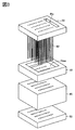
図3は、セラミック成形体の製造に使用される成形型の分解斜視図である。
図4は、セラミック成形体の製造に使用される成形型の平面図である。
図5は、図4の5−5線に沿って成形型を切断した成形型の縦断面図である。
図6は、成形空間部分の周りを示した図5の一部拡大図である。
図7は、第2孔の周りを示した図6の一部拡大図である。
図8は、下型の上に外型を載せる(積層する)工程を示した図である。
図9は、外型の上に上型を載せる(積層する)工程を示した図である。
図10は、上型の上にピンが一体固定されたピンホルダを載せる(積層する)工程を示した図である。
図11は、スラリー貯留部にセラミックスラリーが貯留された状態を示した図である。
図12は、成形空間内にセラミックスラリーが充填された状態を示した図である。
図13は、ピンが一体固定されたピンホルダを上型から上方へ引き抜く工程を示した図である。
図14は、上型を外型から上方へ引き抜く工程を示した図である。
図15は、下型を外型から下方へ引き抜く工程を示した図である。
図16は、2次硬化工程において外型に付着している成形体が収縮する様子を示した図である。
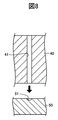
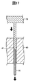
図17は、成形体を外型から押し出す工程を示した図である。
図18は、本発明の実施形態に係るセラミック成形体の製造方法の手順を示したフローチャートである。
図19は、本発明の実施形態の変形例に係る第2孔の周りを示した図7に対応する図である。
図20は、本発明の実施形態の他の変形例に係る第2孔の周りを示した図7に対応する図である。
図21は、本発明の実施形態の他の変形例に係る成型空間部分の周りを示した図6に対応する図である。
図22は、図21に示した成形型を用いて製造されたセラミック成形体の斜視図である。
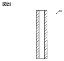
図23は、図21に示した成形型を用いて製造されたセラミック成形体の主要断面図である。
図24は、本発明の実施形態の他の変形例に係る成形型の図3に対応する分解斜視図である。
図25は、本発明の実施形態における、注入工程、及び充填工程(負圧調整工程)を説明するための図5に対応する図である。
図26は、本発明の実施形態における、充填工程(大気圧復帰工程)を説明するための図5に対応する図である。
図27は、本発明の実施形態の変形例Aに使用される成形型の分解斜視図である。
図28は、本発明の実施形態の変形例Aにおける、注入工程、及び充填工程(負圧調整工程)を説明するための図5に対応する図である。
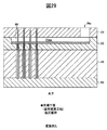
図29は、本発明の実施形態の変形例Aにおける、充填工程(姿勢変更工程)を説明するための図5に対応する図である。
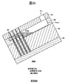
図30は、本発明の実施形態の変形例Aにおける、充填工程(大気圧復帰工程)を説明するための図5に対応する図である。
図31は、本発明の実施形態の変形例Bに使用される成形型の分解斜視図である。
図32は、本発明の実施形態の変形例Bにおける、注入工程、及び充填工程(負圧調整工程)を説明するための図5に対応する図である。
図33は、本発明の実施形態の変形例Bにおける、充填工程(姿勢変更工程)を説明するための図5に対応する図である。
図34は、本発明の実施形態の変形例Bにおける、充填工程(大気圧復帰工程)を説明するための図5に対応する図である。
図35は、本発明の実施形態の変形例Cにおける、負圧調整工程を説明するための図5に対応する図である。
図36は、本発明の実施形態の変形例Cにおける、注入工程を説明するための図5に対応する図である。
図37は、本発明の実施形態の変形例Cにおける、大気圧復帰工程を説明するための図5に対応する図である。
図38は、本発明の実施形態の変形例Dにおける、負圧調整工程を説明するための図5に対応する図である。
図39は、本発明の実施形態の変形例Dにおける、注入工程(姿勢変更前)を説明するための図5に対応する図である。
図40は、本発明の実施形態の変形例Dにおける、注入工程(姿勢変更後)を説明するための図5に対応する図である。
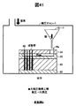
図41は、本発明の実施形態の変形例Dにおける、大気圧復帰工程を説明するための図5に対応する図である。
図42は、本発明の実施形態の変形例Eにおける、負圧調整工程を説明するための図5に対応する図である。
図43は、本発明の実施形態の変形例Eにおける、注入工程(姿勢変更前)を説明するための図5に対応する図である。
図44は、本発明の実施形態の変形例Eにおける、注入工程(姿勢変更後)を説明するための図5に対応する図である。
図45は、本発明の実施形態の変形例Eにおける、大気圧復帰工程を説明するための図5に対応する図である。
図46は、スラリーを貯留する容器が減圧チャンバ外に配置された場合を示した図35に対応する図である。
図47は、容器からのスラリーの流出を止める手段としてコックが使用された場合を示した図46に対応する図である。
図48は、スラリーを貯留する容器として管状容器が採用された場合を示した図35に対応する図である。
図49は、管状容器の姿勢を変更してスラリーを注入した状態を示した図48に対応する図である。FIG. 1 is a perspective view of a ceramic molded body manufactured by a method of manufacturing a ceramic molded body using a gel cast method according to an embodiment of the present invention.
FIG. 2 is a main cross-sectional view of a ceramic molded body manufactured by a method of manufacturing a ceramic molded body using a gel cast method according to an embodiment of the present invention.
FIG. 3 is an exploded perspective view of a mold used for manufacturing a ceramic molded body.
FIG. 4 is a plan view of a mold used for manufacturing a ceramic molded body.
FIG. 5 is a longitudinal cross-sectional view of a mold obtained by cutting the mold along line 5-5 in FIG.
6 is a partially enlarged view of FIG. 5 showing the periphery of the molding space portion.
FIG. 7 is a partially enlarged view of FIG. 6 showing the periphery of the second hole.
FIG. 8 is a diagram showing a process of placing (stacking) the outer mold on the lower mold.
FIG. 9 is a diagram showing a process of placing (stacking) the upper mold on the outer mold.
FIG. 10 is a diagram showing a process of placing (stacking) a pin holder in which pins are integrally fixed on an upper mold.
FIG. 11 is a diagram illustrating a state in which the ceramic slurry is stored in the slurry storage unit.
FIG. 12 is a view showing a state in which ceramic slurry is filled in the forming space.
FIG. 13 is a view showing a process of pulling out the pin holder, to which the pin is integrally fixed, upward from the upper mold.
FIG. 14 is a diagram illustrating a process of pulling the upper mold upward from the outer mold.
FIG. 15 is a diagram illustrating a process of pulling the lower mold downward from the outer mold.
FIG. 16 is a view showing a state in which the molded body attached to the outer mold contracts in the secondary curing step.
FIG. 17 is a view showing a process of extruding the molded body from the outer mold.
FIG. 18 is a flowchart showing the procedure of the method for manufacturing a ceramic molded body according to the embodiment of the present invention.
FIG. 19 is a view corresponding to FIG. 7 showing the periphery of the second hole according to a modification of the embodiment of the present invention.
FIG. 20 is a view corresponding to FIG. 7 showing the periphery of the second hole according to another modification of the embodiment of the present invention.
FIG. 21 is a view corresponding to FIG. 6 showing the periphery of a molding space portion according to another modification of the embodiment of the present invention.
22 is a perspective view of a ceramic molded body manufactured using the mold shown in FIG.
FIG. 23 is a main cross-sectional view of a ceramic molded body produced using the mold shown in FIG.
24 is an exploded perspective view corresponding to FIG. 3 of a mold according to another modification of the embodiment of the present invention.
FIG. 25 is a view corresponding to FIG. 5 for explaining the injection step and the filling step (negative pressure adjusting step) in the embodiment of the present invention.
FIG. 26 is a view corresponding to FIG. 5 for explaining the filling step (atmospheric pressure return step) in the embodiment of the present invention.
FIG. 27 is an exploded perspective view of a mold used in Modification A of the embodiment of the present invention.
FIG. 28 is a view corresponding to FIG. 5 for explaining the injection step and the filling step (negative pressure adjusting step) in Modification A of the embodiment of the present invention.
FIG. 29 is a diagram corresponding to FIG. 5 for describing the filling step (posture changing step) in Modification A of the embodiment of the present invention.
FIG. 30 is a diagram corresponding to FIG. 5 for illustrating the filling step (atmospheric pressure return step) in Modification A of the embodiment of the present invention.
FIG. 31 is an exploded perspective view of a mold used in Modification B of the embodiment of the present invention.
FIG. 32 is a view corresponding to FIG. 5 for explaining the injection step and the filling step (negative pressure adjusting step) in Modification B of the embodiment of the present invention.
FIG. 33 is a diagram corresponding to FIG. 5 for describing the filling step (posture changing step) in Modification B of the embodiment of the present invention.
FIG. 34 is a diagram corresponding to FIG. 5 for illustrating the filling step (atmospheric pressure return step) in Modification B of the embodiment of the present invention.
FIG. 35 is a diagram corresponding to FIG. 5 for describing the negative pressure adjusting step in Modification C of the embodiment of the present invention.
FIG. 36 is a diagram corresponding to FIG. 5 for describing the injection step in Modification C of the embodiment of the present invention.
FIG. 37 is a diagram corresponding to FIG. 5 for describing the atmospheric pressure return step in Modification C of the embodiment of the present invention.
FIG. 38 is a diagram corresponding to FIG. 5 for describing the negative pressure adjusting step in Modification D of the embodiment of the present invention.
FIG. 39 is a diagram corresponding to FIG. 5 for illustrating the injection step (before the posture change) in Modification D of the embodiment of the present invention.
FIG. 40 is a diagram corresponding to FIG. 5 for illustrating the injection step (after the posture change) in Modification D of the embodiment of the present invention.
FIG. 41 is a diagram corresponding to FIG. 5 for describing the atmospheric pressure return step in Modification D of the embodiment of the present invention.
FIG. 42 is a diagram corresponding to FIG. 5 for describing the negative pressure adjusting step in Modification E of the embodiment of the present invention.
FIG. 43 is a diagram corresponding to FIG. 5 for describing the injection step (before the posture change) in Modification E of the embodiment of the present invention.
FIG. 44 is a diagram corresponding to FIG. 5 for illustrating the injection step (after the posture change) in Modification E of the embodiment of the present invention.
FIG. 45 is a diagram corresponding to FIG. 5 for describing the atmospheric pressure return step in Modification E of the embodiment of the present invention.
FIG. 46 is a view corresponding to FIG. 35 illustrating a case where the container for storing the slurry is disposed outside the decompression chamber.
FIG. 47 is a view corresponding to FIG. 46 showing a case where a cock is used as means for stopping the outflow of slurry from the container.
FIG. 48 is a view corresponding to FIG. 35 showing a case where a tubular container is employed as a container for storing slurry.
FIG. 49 is a view corresponding to FIG. 48 showing a state in which slurry is injected by changing the posture of the tubular container.
以下、図面を参照しつつ本発明の実施形態に係る成形型、及びこの成形型を用いたセラミック成形体の製造方法について説明する。
図1及び図2は、本発明の実施形態に係るゲルキャスト法を利用したセラミック成形体の製造方法により製造されたセラミック成形体10の斜視図、及び主要断面図である。このセラミック成形体10は、一端に底を有する超細長の円筒状を呈していて、中空部(凹部)を有する円筒状部11と、円筒状部11の一端に設けられた底部12とから構成されている。この成形体10を焼成して得られる焼結体は、例えば、プラズマ発生用の電極等として利用され得る。
以下、本発明によるセラミック成形体10の製造方法の実施形態について、図3〜図18を参照しながら説明する。先ず、この製造方法に使用される成形型について説明する。図3、図4、及び図5はそれぞれ、セラミック成形体10の製造に使用される成形型の分解斜視図、平面図、及び図4の5−5線に沿って組立完了状態にある成形型を切断した組立完了状態にある成形型の縦断面図である。図3〜図5に示すように、この成形型を利用すれば、40個のセラミック成形体10を同時に製造することができる。
この成形型は、直方体状のピンホルダ20、上型30、外型40、及び下型50、並びに、超細長の円柱状の(40本の)ピン60から構成される。(40本の)ピン60はそれぞれ、上下(鉛直)方向において互いに平行に且つ水平方向においてマトリクス状(10×4)に整列するようにピンホルダ20に対して周知の手法(嵌合固定、螺合固定等)により予め一体固定されている。このピンホルダ20及び(40本の)ピン60からなる一体物が前記「内型」に対応し、(40本の)ピン60が「内型」の「挿入部」に対応している。また、上型30が前記「上型」に、外型40が前記「外型」に対応している。
本例では、外型40のみがフッ素樹脂から構成され、その他のピンホルダ20、上型30、下型50、及び(40本の)ピン60がアルミニウム合金(例えば、ジュラルミン等)から構成される。なお、ピンホルダ20、上型30、及び下型50も、フッ素樹脂から構成されてよい。ただし、超細長で剛性が極めて低いピン60は、フッ素樹脂から構成されてよいが、アルミニウム合金から構成されることが好ましい。
後述のように作成されるセラミックスラリーは、ピンホルダ20に形成された注型口Pinから、上型30の上面に形成された直方体状の凹部であるスラリー貯留部Presに注入され、その後、スラリー貯留部Presよりも下方の図5において白抜きの箇所に充填されるようになっている。以下、説明の便宜上、40個のセラミック成形体10のうちの1つに着目して説明を続けるが、その他のものについても同様である。
図5の一部断面図である図6に示すように、組立完了状態において、下型50、外型40、上型30、及び「内型」(ピンホルダ20)は、この順で下から積層・固定されている。組立完了状態において、(40本の)ピン60のそれぞれが対応する第1孔41及び第2孔31に同軸的に貫通するように、外型40に上下方向に貫通する円筒状(円柱状)の(40個の)第1孔41が、並びに、上型30に上下方向に貫通する円筒状の(40個の)第2孔31が、水平方向においてマトリクス状(10×4)に整列するようにそれぞれ形成されている。更には、組立完了状態において、(40本の)ピン60のそれぞれが対応する凹部51と同軸的に位置するように、下型50の上面に球状の(40個の)凹部51が、水平方向においてマトリクス状(10×4)に整列するようにそれぞれ形成されている。
この組立完了状態において、ピン60の側部表面と第1孔41の内壁とで挟まれた空間S1に充填されたセラミックスラリーが後に上記セラミック成形体10の円筒状部11になり、ピン60の先端部表面と凹部51の内壁とで挟まれた空間S2に充填されたセラミックスラリーが後に上記セラミック成形体10の底部12になる。即ち、空間S1と空間S2とを合わせた空間(S1+S2)がセラミック成形体10を成形するための前記成形空間に対応する。
図6における第2孔31の近傍の拡大図である図7に示すように、第1孔41の内径D1は第2孔31の内径D2よりも大きい。この結果、組立完了状態において、第2孔31の下側の開口全体が第1孔41の上側の開口に含まれるように第2孔31の下側の開口と第1孔41の上側の開口とが接続される。
ピン60の直径Dpは、D2に対して若干小さい。従って、組立完了状態において、第2孔31の内壁とピン60の側部表面とで挟まれた環状の狭空間(微小隙間)が形成される。以下、この環状の空間を「スラリー流通隙間S3」と称呼する。
スラリー流通隙間S3の上端は第2孔31の上側の開口と繋がっていて、スラリー流通隙間S3の下端は空間S1と繋がっている。即ち、スラリー貯留部Presは、スラリー流通隙間S3を介して成形空間(S1+S2)と繋がっている。従って、スラリー貯留部Presに注入されたセラミックスラリーは、図6に太い黒矢印で示したように、重力の作用等により、スラリー流通隙間S3を介して成形空間(S1+S2)に向けて落下・流入し得るようになっている。なお、成形空間(S1+S2)は、スラリー流通隙間S3に対応する(接続する)部分を除いて、上型30、外型40、及び下型50により気密的に画定されている。
次に、セラミック成形体10の具体的な製造方法について説明する。図18は、この製造方法の手順を示したフローチャートである。
(離型剤塗布)
先ず、上型30、下型50、及びピン60の成形面(セラミックスラリーが接触する面)に、離型剤として、フッ素系離型剤を有機溶剤で分散させたものを塗布する。塗布方法は周知の手法の中から適宜選択され得る。本例では、上型30及び下型50への塗布は、スプレーガンを用いて行うことが望ましい。一方、ピン60への塗布は、ディッピングにより行うことが望ましい。
塗布後、有機溶剤は直ちに揮発し、この結果、成形面にはフッ素系離型剤が固着される。これにより、フッ素系離型剤が固着された成形面に対するセラミックスラリーの接触角が60°以上となる。なお、上述のごとく、外型40はフッ素樹脂から構成されている。従って、離型剤の塗布なしで、外型40の成形面に対するセラミックスラリーの接触角は60°以上となっている。
以上より、後述するように成形体から型を取り除く際(離型の際)、成形体の残渣が型の成形面に付着・残存し難くなる。従って、型の離型の際の成形体の表面の破損を抑制することができる。加えて、型の成形面に成形体の残渣が付着・残存していても、これを容易に除去できる。
(成形型組み立て)
次に、成形型を組み立てる。図8〜図10は、その手順を示す。先ず、図8に示すように、下型50の上に外型40を載せる(積層する)。次いで、図9に示すように、外型40の上に上型30を載せる(積層する)。最後に、図10に示すように、ピンホルダ20に既に一体固定されている(40本の)ピン60をそれぞれ、対応する第1孔41及び第2孔31に上方から挿入しながら、上型30の上にピンホルダ20を載せる(積層する)。これにより、成形型の組み立てが完了し、成形型が組立完了状態となる(図4、及び図5に示した状態を参照)。以上、係る成形型の組立に際し、下型50、外型40、上型30、及びピンホルダ20のそれぞれの移動は、周知のスライダ(図示せず)を用いて、別個独立に且つ上下方向にのみ行われる。
(セラミックスラリー調製)
次に、セラミック粉体、分散媒、ゲル化剤、及び触媒を含むセラミックスラリーの調製を行う。セラミックスラリーには、セラミック粉体、分散媒、ゲル化剤が含まれる。また、必要に応じて分散助剤、触媒が含まれる。
本例では、セラミックスラリーとしては、セラミック粉体として、ジルコニア粉末100重量部、分散媒として、脂肪族多価エステルと多塩基酸エステルの混合物27重量部、及び、エチレングリコール0.3重量部、ゲル化剤として、4,4’−ジフェニルメタンジイソシアネート5.3重量部、分散助剤として、ポリカルボン酸系共重合体3重量部、触媒として、6−ジメチルアミノ−1−ヘキサノール0.05重量部、を混合したものを使用した。
なお、セラミック粉体として、ジルコニア、アルミナ、シリカ、フェライト、チタン酸バリウム、チッ化ケイ素、炭化ケイ素等が使用されてもよい。分散媒として、脂肪族多価エステル、多塩基酸エステル、トルエン、キシレン、メチルエチルケトンなどの有機溶剤が使用されてもよい。ゲル化剤として、フェノール樹脂、ウレタン樹脂、アクリル樹脂、又はこれらの前駆体が使用されてもよい。分散助剤として、ポリカルボン酸系共重合体、ソルビタン系エステルなどの有機化合物が使用されてもよい。触媒として、6−ジメチルアミノ−1−ヘキサノールなどのアミン化合物が使用されてもよい。
(セラミックスラリー注入)
次に、組立完了状態にある成形型を大気圧の雰囲気に曝した状態において、且つ、成形型の姿勢が水平に維持された状態で、セラミックスラリーをスラリー貯留部Presへ注入する。このセラミックスラリー注入は、上記セラミックスラリーの調製後、直ちに開始される。上述したように、セラミックスラリーは、注型口Pinから注入される。注入されたセラミックスラリーは、図11に示すように、スラリー貯留部Presに貯留される。このセラミックスラリーの注入は、スラリー貯留部Presに目標とする量のスラリーが貯留されるまで継続される。これにより、第2孔31の上側の開口(スラリー流通隙間S3の上端、40か所)は、スラリー貯留部Presに貯留されているセラミックスラリーにより塞がれる。
(セラミックスラリー充填)
次に、成形型の姿勢が水平に維持された状態、即ち、第2孔31の上側の開口がスラリー貯留部Presに貯留されているセラミックスラリーにより塞がれた状態で、スラリー貯留部Presに貯留されているセラミックスラリーを(40個の同形の)成形空間(S1+S2)に充填する。スラリー貯留部Presに貯留されているセラミックスラリーは、重力の作用によって、スラリー流通隙間S3(図7を参照)を介して成形空間(S1+S2)に向けて自然に落下・流入し得る。しかしながら、上述のごとく、スラリー流通隙間S3は微小隙間である。従って、重力の作用のみでは、セラミックスラリーがスラリー流通隙間S3を通過し難く、従って、成形空間に向けて落下し難い。
そこで、本例では、図11に示すように、スラリー貯留部Presに貯留されたセラミックスラリーが成形空間(S1+S2)に向けて(全く、或いは殆ど)落下・流入していない状態において、周知の負圧発生装置を利用する(減圧チャンバ内に成形型を収容する)などして、成形型の雰囲気の圧力を大気圧よりも低い所定の負圧に調整・維持する。
成形型の雰囲気の圧力が所定の負圧に調整された直後では、成形空間(S1+S2)内の圧力は未だ大気圧に維持されている。その後、成形空間(S1+S2)内の空気が、スラリー流通隙間S3、並びに、第2孔31の上側の開口を塞いでいるセラミックスラリーの内部を介して成形型の雰囲気に向けて徐々に吸引されていくことで、成形空間(S1+S2)内の圧力も所定の負圧にまで徐々に低下していく。このように成形型の雰囲気の圧力を所定の負圧に維持する作業は、成形空間(S1+S2)内の圧力が所定の負圧にまで確実に低下したと考えられるまでの十分長い期間に亘って行われる。
なお、前記「負圧」が大き過ぎる(真空に近過ぎる)と、スラリー中の分散媒(液体)の気化が発生して成形空間内(スラリー内)に気化した分散媒による空隙が発生する。一方、前記「負圧」が小さ過ぎる(大気圧に近過ぎる)と、成形空間内にスラリーが充填され得ない部分が発生して成形空間内に空気による空隙が発生する。即ち、前記「負圧」には、分散媒による空隙発生の抑制、及び空気による空隙発生の抑制が考慮された適正値が存在する。
次いで、成形型の雰囲気の圧力を大気圧に再び戻す。成形型の雰囲気の圧力が大気圧に戻された直後では、成形空間(S1+S2)内の圧力は未だ所定の負圧に維持されている。この結果、スラリー貯留部Presの雰囲気と成形空間(S1+S2)内とで差圧が生じる。この差圧は、(スラリー貯留部Presに貯留されている)第2孔の上側の開口を塞いでいるスラリーをスラリー流通隙間S3を介して成形空間(S1+S2)に積極的に落下・流入させる駆動力として機能する。
このように、注入工程及び充填工程に亘って成形型の姿勢が水平に維持しながら、セラミックスラリー注入後の成形型の雰囲気を大気圧→負圧→大気圧と推移させることで、スラリー貯留部Presに貯留されているスラリーは、重力の作用のみならず、前記差圧の作用によっても、スラリー流通隙間S3を介して成形空間(S1+S2)に向けて落下・流入していく。これにより、図12に示すように、成形空間(S1+S2)内の全てにおいてスラリーが確実に充填され得る。換言すれば、成形空間(S1+S2)内においてスラリーが充填されない部分が発生することをより確実に抑制することができる。
また、本例のように、前記差圧の作用をも利用する場合、セラミックスラリーの粘度が大きい場合であっても、成形空間(S1+S2)全体にスラリーを確実に充填することができる。本例では、完成したセラミック成形体10を焼成して得られる焼結体(セラミック化されたもの)を検査したところ、内部に空隙は検出されなかった。
これに対し、前記差圧の作用を利用せずに重力の作用のみを利用してスラリーを成形空間(S1+S2)に向けて落下・流入させる場合、成形空間(S1+S2)内においてスラリーが充填されない部分が発生し得、このことが原因で、完成したセラミック成形体10を焼成して得られる焼結体に欠陥が発生し得る。
(1次硬化)
次に、1次硬化工程を行う。1次硬化工程では、セラミックスラリーの成形空間(S1+S2)内への充填完了から所定時間が経過するまでの間、セラミックスラリーが充填された成形型を室温雰囲気で放置する。この間、セラミックスラリーは、主としてウレタン反応により、ゾル、ゲル、脆い固体(分散媒により湿潤しているがそれ自身で一定の形を保持できる程度に固化した成形体)へと次第に硬化していく。
図12に示すように、スラリー貯留部Pres内にセラミックスラリーの余剰分が残存する状態で1次硬化工程を実行すると、成形体は、成形空間(S1+S2)の形状に対応する部分(以下、「成形空間部成形体」と称呼する。)と、スラリー流通隙間S3及びスラリー貯留部Pres内のセラミックスラリー余剰分の形状に対応する部分(以下、「余剰部成形体」と称呼する。)と、が連続した一体形状を有する成形体(以下、「一体成形体」と称呼する。)となる。
ここで、ウレタン反応そのものでは成形体の収縮は殆ど発生しない。加えて、成形空間部成形体は、上型30、外型40、及び下型50で囲まれているから(即ち、閉空間内にあるから)、成形空間部成形体から分散媒の揮発は殆ど発生しない。従って、成形空間部成形体における分散媒の揮発(即ち、分子数の減少)による収縮も殆ど発生しない。
以上より、1次硬化工程が終了した段階では、成形空間部成形体の収縮が殆ど発生しない。換言すれば、1次硬化工程は、成形空間部成形体の収縮を抑えつつセラミックスラリーをウレタン反応により脆い固体に変化させる工程である。従って、1次硬化工程において、ピン60の表面を囲んでいる成形空間部成形体の収縮に起因して同成形空間部成形体に作用する引っ張り応力により成形空間部成形体に亀裂等の損傷が発生するという問題が発生し難い。なお、1次硬化工程終了時点では、余剰部成形体は、分散媒により湿潤した紙粘土状の固体となっていた。
なお、1次硬化工程が終了後、離型剤の溶融温度以下の範囲内において加熱を行ってもよい。これにより、ウレタン反応が更に進み、成形体は、上記脆い固体から、後述する内型除去工程時、上型除去工程時、及び下型除去工程時に受ける外力に耐え得る強度を備えた固体へと硬化し易くなる。
(内型除去)
加熱工程終了後、直ちに、図13に示すように、「内型」(即ち、ピンホルダ20とピン60(40本)との一体物)を上型30から上方へ引き抜く。即ち、ピン60を一体成型体(=成形空間部成形体+余剰部成形体)から上方へ引き抜く。
ここで、一体成形体からピン60が上方に向けて引き抜かれる際、一体成形体は、上向きの力を受ける。この上向きの力は、一体成形体を上方に向けて外型40及び上型30から引き抜く力としても機能し得る。他方、上述のように、外型40の第1孔41の内径D1が上型30の第2孔31の内径D2よりも大きい(図7を参照)。従って、この状態(即ち、外型40の上面に上型30が積層された状態)では、第2孔31の下側の開口面の全体が第1孔41の上側の開口面に含まれる。従って、一体成形体における成形空間部成形体と余剰部成形体との接続部分において段差部が形成される。これにより、一体成形体に対して一体成形体を上方に向けて外型40から引き抜く力が作用しても、この段差部が上型40の下面(第2孔41の下側の開口の外側近傍部分)に係止される。
この結果、一体成形体(特に、成形空間部成形体)が外型40から抜けることが防止される。換言すれば、一体成形体からピン60が上方に向けて引き抜かれる際、一体成形体(特に、成形空間部成形体)を外型40側に確実に残すことができる。この点において、スラリー流通隙間S3(即ち、微小隙間)は、所謂ストリッパとして機能するということもできる。
(上型除去)
次に、図14に示すように、上型30を外型40から上方へ引き抜く。このとき、一体成形体における成形空間部成形体と余剰部成形体との接続部分(即ち、上記段差部)にて分断が生じ、上型30が成形空間部成形体から剥離・除去されるとともに、成形空間部成形体が外型40側に付着・残存する。
(下型除去)
次に、図15に示すように、下型50を外型40から下方へ引き抜く。これにより、下型50が成形空間部成形体から剥離・除去されるとともに、成形空間部成形体全体が外型40側に付着・残存する。なお、上述した上型除去工程、及び下型除去工程は、後述する2次硬化工程後に行われてもよい。なお、「内型」、上型30、下型50の除去は、上述した離型剤の作用により容易となっている。
(2次硬化)
次に、2次硬化工程を行う。2次硬化工程では、成形空間部成形体が付着・残存している外型40を室温雰囲気で放置する。なお、離型剤の溶融温度以下の範囲内において加熱を行ってもよい。また、離型剤としてワックスが使用されている場合、ワックスを溶融させて外型40を離型するため、積極的に加熱を行う。この状態では、成形空間部成形体の上方が外部に露呈しているから、分散媒の揮発が非常に行われ易い。従って、この間、成形空間部成形体は、主として、同成形空間部成形体内に含まれる分散媒の揮発により次第に硬化していく。なお、2次硬化工程においても、ウレタン反応は継続して進行していく。
この結果、図16に示すように、分散媒の揮発(即ち、分子数の減少)により成形空間部成形体が収縮していく。即ち、2次硬化工程が終了した段階では成形空間部成形体の収縮が顕著に発生する。換言すれば、2次硬化工程は、成形空間部成形体を積極的に収縮させるとともに成形空間部成形体をより一層硬化させる工程である。なお、2次硬化工程終了後においても、(焼成前の)成形空間部成形体は脆く(可塑性が殆どなく)、その強度はプラスチック等に比して著しく小さい。
これにより、2次硬化工程後では、成形空間部成形体は自身の収縮により外型40から剥離し易い状態になる(或いは、剥離する)。実際、2次硬化工程後において、40個のうち一部の成形空間部成形体が外型40から剥離していることが確認できた。
(外型除去)
次に、図17に示すように、未だ外型40から剥離していない成形空間部成形体を、押し出し治具70を用いて外型40から押し出す。これにより、40個の成形空間部成形体が取り出された。なお、外型40の除去は、外型40の材質がフッ素樹脂であることに起因して容易となっている。
以上、「内型」、上型30、下型50、及び外型40の除去に際し、ピンホルダ20、上型30、下型50、押し出し治具70のそれぞれの移動は、周知のスライダ(図示せず)を用いて、別個独立に且つ上下方向にのみ行われる。
(最終乾燥)
最後に、40個の成形空間部成形体を100℃に設定されたオーブンに載せて、180分間加熱して40個のセラミック成形体10(図1、及び図2を参照)を得る。この最終乾燥工程により、分散媒の揮発、及びウレタン反応が更に進み、セラミック成形体10の強度がより一層大きくなる。これにより、セラミック成形体10の取り扱いが容易となる。なお、この最終乾燥は省略可能である。
以上、説明したように、中空部を有するセラミック成形体10を成形するための本発明に係る成形型の実施形態では、下型50、外型40、上型30、及び「内型(ピンホルダ20とピン60の一体物)」が、この順で下から積層・固定されている。組立完了状態にて、ピン60が外型40の第1孔41及び上型30の第2孔31に同軸的に挿入されている。第2孔31の内径は、第1孔41の内径よりも小さくピン60の外径よりも若干大きい。組立完了状態にて、ピン60の側部表面と第1孔41との間にセラミック成形体10を成形するための成形空間(S1+S2)が形成され、ピン60の側部表面と第2孔31との間にセラミック流通隙間S3(環状の微小隙間)が形成される。成形型の姿勢が水平に維持された状態で上型30の上面に形成されているスラリー貯留部Presに注入されたセラミックスラリーは、第2孔31の上側の開口(スラリー流通隙間S3の上端、40か所)を塞ぎ、その後、セラミック流通隙間S3を介して成形空間(S1+S2)へ落下・流入することで、成形空間(S1+S2)内に充填される。
ここで、成形型の姿勢が水平に維持され且つ第2孔31の上側の開口がスラリー貯留部Presに貯留されているセラミックスラリーにより塞がれた状態で、セラミックスラリー注入後の成形型の雰囲気を大気圧→負圧→大気圧と推移させることで、スラリー貯留部Presに貯留されたスラリーは、重力の作用のみならず、前記「差圧」の作用によっても、スラリー流通隙間S3を介して成形空間(S1+S2)に向けて落下・流入していく。これにより、成形空間(S1+S2)内の全てにおいてスラリーが確実に充填され得る。
また、成形空間内に充填されたセラミックスラリーが硬化された後にて「内型」(即ち、ピンホルダ20とピン60との一体物)が上型30から上方へ引き抜かれる際、成形空間内の成形体(即ち、上記成形空間部成形体)は、上向きの力を受ける。このとき、第2孔31の内径が第1孔41の内径よりも小さいことから、成形空間部成形体の上面が上型40の下面(第2孔41の下側の開口の外側近傍部分)に係止される。この結果、成形空間部成形体が外型40から抜けることが防止される。即ち、成形空間部成形体を外型40側に確実に残すことができる。
このように、スラリー流通隙間S3を微小隙間とすることで、スラリー貯留部Presに貯留されたスラリーが重力の作用のみでは成形空間へ落下し難くなる一方で、「内型」除去時における所謂ストリッパの機能が達成される。スラリー貯留部Presに貯留されたスラリーが成形空間へ落下し難くなる点は、上述した前記「差圧」の作用を利用することで補償され得る。
なお、本発明は上記実施形態に限定されることはなく、本発明の範囲内において種々の変形例を採用することができる。例えば、上記実施形態においては、図7に示すように、上型30の第2孔31は、円筒状(円柱状)の貫通孔であったが、図19、図20に示すように、この貫通孔の内壁に、貫通孔の上下の開口に通じる上下方向に延びる溝31aが形成されてもよい(図19では、180°等配で2本、図20では、90°等配で4本)。
これにより、スラリー流通隙間S3において、溝に31a対応する隙間間隔の広い部分と溝31aに対応しない隙間間隔の狭い部分とが形成され得る。この結果、溝31aに対応しない隙間間隔の狭い部分の存在により上記ストリッパとしての機能が確実に保持されたまま、溝31aに対応する隙間間隔の広い部分の存在によりセラミックスラリーのスラリー貯留部Presから成形空間(S1+S2)への移動(落下)を容易とすることができる。このように、セラミックスラリーのスラリー貯留部Presから成形空間(S1+S2)への移動(落下)が容易になると、セラミックスラリーの成形空間(S1+S2)への充填に要する時間を短くすることができる。更には、成形空間(S1+S2)内においてセラミックスラリーが充填され得ない部分が発生することを抑制することができる。
また、上記実施形態において、図21に示すように、下型50’の上面に(40個の)ピン60’の先端の形状に対応する形状を有する凹部を形成し、組立完了状態においてピン60の先端が前記凹部内に進入・密着するようにピン60’の長さを調整してもよい。この成形型を使用して上記と同様の手法によりセラミック成形体を製造すると、図22、図23に示すように、両端が開口する円筒状のセラミック成形体10’が得られる。この成形体10’を焼成して得られる焼結体は、例えば、プラズマ発生用の電極等として利用され得る。
また、上記実施形態において、図24に示すように、外型40’が、互いに平行な複数(本例では、4つ)の各列に整列する複数(本例では、10個)の第1孔のそれぞれの軸線を含む平面で分離可能に構成されていてもよい。これにより、セラミック成形体の成形後において、外型40’を複数(本例では、5つ)の部分に分割することで、全ての第1孔の内壁を露出させることができる。従って、第1孔の内壁(成形面)にセラミック成形体の残渣が付着・残存していても、これを容易に除去できる。
また、上記実施形態においては、成形型が組まれる前に成形型の成形面(上型30、下型50、及びピン60の成形面)に、離型剤として、フッ素系離型剤を有機溶剤で分散させたものが塗布されているが、離型剤として、ワックスを有機溶剤で分散させたものが使用されてもよい。この場合、塗布方法は周知の手法の中から適宜選択され得るが、上型30及び下型50へのワックスの塗布は、スプレーガンを用いて行うことが望ましい。一方、ピン60へのワックスの塗布は、ディッピングにより行うことが望ましい。
また、上記実施形態においては、前記離型剤の塗布に代えて、フッ素樹脂コーティング等の表面処理を行っても良い。この場合、フッ素樹脂コーティングは、成形型の成形面に直接行われてもよいし、同成形面に所定の下塗り、メッキ、アルマイト処理等を施した状態で行われてもよい。
また、上記実施形態においては、1次硬化工程中では加熱が行われていないが、離型剤(特に、フッ素系離型剤)の溶融温度以下の範囲内において加熱が行われてもよい。同様に、2次硬化工程中では加熱が行われていないが、離型剤(特に、フッ素系離型剤)の溶融温度以下の範囲内において加熱が行われてもよい。
加えて、上記実施形態においては、注入工程及び充填工程に亘って成形型の姿勢が水平(=前記「第1の姿勢」)に維持されているが、注入工程及び充填工程において第2孔31の上側の開口(スラリー流通隙間S3の上端、40か所)がセラミックスラリーにより塞がれる状態が確保できる限りにおいて、注入工程及び充填工程に亘って成形型の姿勢が「水平から傾いた姿勢」(傾斜姿勢)で一定に維持されてもよい。
ところで、上記実施形態では、図25に示すように、成形型の姿勢が水平に維持された状態で「注入工程」が実行されて、第2孔31の上側の開口(スラリー流通隙間S3の上端、40か所)がセラミックスラリーにより塞がれるようにセラミックスラリーがスラリー貯留部Presに貯留される。次いで、成形型の姿勢が水平に維持され、且つ、スラリー貯留部Presに貯留されているセラミックスラリーにより第2孔31の上側の開口が塞がれた状態で、「充填工程」における「負圧調整工程」(大気圧→負圧)が実行される。そして、図26に示すように、成形型の姿勢が水平に維持され、且つ、セラミックスラリーにより第2孔31の上側の開口が塞がれた状態で、「充填工程」における「大気圧復帰工程」(負圧→大気圧)が実行される。即ち、上記実施形態では、注入工程及び充填工程に亘って成形型の姿勢が水平に維持される。
この結果、上記実施形態では、「負圧調整工程」の過程において、成形空間(S1+S2)内の空気が、第2孔31の上側の開口を塞いでいるセラミックスラリーの内部を介して外部へ排出される。このことに起因して、セラミックスラリー内に気泡が混入する可能性がある。混入した気泡は、スラリー中に溶解し得る。スラリーの粘度が大きい場合、溶解した気泡はスラリー外部へ排出され難い。係る気泡の混入を防止するため、以下に述べる変形例A、Bが考えられる。
変形例Aでは、図27に示すように、成形空間の個数が40(4×10)から16(4×4)に減少している点を除いて図3に示す上記実施形態の成形型と同じ成形型が使用される。先ず、図28に示すように、成形型の姿勢が「水平から傾いた姿勢」(傾斜姿勢)に維持された状態で「注入工程」が実行されて、第2孔31の上側の開口(スラリー流通隙間S3の上端、16か所)がセラミックスラリーにより塞がれないように(即ち、セラミックスラリーが第2孔31の上側の開口(16か所)の上部に存在しないように)、セラミックスラリーがスラリー貯留部Presに貯留される。次いで、成形型の姿勢が傾斜姿勢に維持され、且つ、スラリー貯留部Presに貯留されているセラミックスラリーにより第2孔31の上側の開口が塞がれていない状態で、「充填工程」における「負圧調整工程」(大気圧→負圧)が実行される。
次いで、図29に示すように、成形型の雰囲気の圧力が負圧に維持された状態で、「充填工程」における「姿勢変更工程」が実行される。「姿勢変更工程」では、成形型の姿勢が傾斜姿勢から水平に変更される。この結果、スラリー貯留部Presに貯留されているセラミックスラリーが第2孔31の上側の開口(16か所)の上部に移動し、第2孔31の上側の開口(16か所)がセラミックスラリーにより塞がれる。そして、図30に示すように、成形型の姿勢が水平に維持され、且つ、セラミックスラリーにより第2孔31の上側の開口が塞がれた状態で、「充填工程」における「大気圧復帰工程」(負圧→大気圧)が実行される。即ち、変形例Aでは、充填工程の途中で成形型の姿勢が傾斜姿勢から水平に変更される。
この変形例Aでは、スラリー貯留部Presに貯留されているセラミックスラリーにより第2孔31の上側の開口が塞がれていない状態で「負圧調整工程」(大気圧→負圧)が実行される。従って、成形空間(S1+S2)内の空気がスラリー貯留部Presに貯留されているセラミックスラリーの内部を介して外部へ排出される事態が発生しない。この結果、セラミックスラリー内への気泡の混入が防止され得る。
変形例Bでは、図31に示すように、スラリー貯留部Presの一部分において他の部分よりも深さが大きいスラリー準備部Pres1が形成された点を除いて図27に示す上記変形例Aの成形型と同じ成形型が使用される。先ず、図32に示すように、成形型の姿勢が水平に維持された状態で「注入工程」が実行されて、スラリー貯留部Presの一部であるスラリー準備部Pres1にセラミックスラリーの全てが注入される。これにより、第2孔31の上側の開口(スラリー流通隙間S3の上端、16か所)は、スラリー貯留部Pres(具体的には、スラリー準備部Pres1)に貯留されているセラミックスラリーにより塞がれない。次いで、成形型の姿勢が水平に維持され、且つ、スラリー貯留部Pres(具体的には、スラリー準備部Pres1)に貯留されているセラミックスラリーにより第2孔31の上側の開口が塞がれていない状態で、「充填工程」における「負圧調整工程」(大気圧→負圧)が実行される。
次いで、図33に示すように、成形型の雰囲気の圧力が負圧に維持された状態で、「充填工程」における「姿勢変更工程」が実行される。「姿勢変更工程」では、成形型の姿勢が水平から「水平から傾いた姿勢」(傾斜姿勢)に変更される。この結果、スラリー貯留部Pres(具体的には、スラリー準備部Pres1)に貯留されているセラミックスラリーが第2孔31の上側の開口(16か所)の上部に移動し、第2孔31の上側の開口(16か所)がセラミックスラリーにより塞がれる。そして、図34に示すように、成形型の姿勢が傾斜姿勢に維持され、且つ、セラミックスラリーにより第2孔31の上側の開口が塞がれた状態で、「充填工程」における「大気圧復帰工程」(負圧→大気圧)が実行される。即ち、変形例Bでは、充填工程の途中で成形型の姿勢が水平から傾斜姿勢に変更される。
この変形例Bでも、上記変形例Aと同様、スラリー貯留部Presに貯留されているセラミックスラリーにより第2孔31の上側の開口が塞がれていない状態で「負圧調整工程」(大気圧→負圧)が実行される。従って、成形空間(S1+S2)内の空気がスラリー貯留部Presに貯留されているセラミックスラリーの内部を介して外部へ排出される事態が発生しない。この結果、セラミックスラリー内への気泡の混入が防止され得る。
なお、上記変形例A(B)では、充填工程の途中(姿勢変更工程)で成形型の姿勢が傾斜姿勢(水平)から水平(傾斜姿勢)に変更されることで、セラミックスラリーにより第2孔31の上側の開口(16か所)が塞がれていない状態から塞がれている状態に変更されているが、充填工程の途中(姿勢変更工程)で成形型の姿勢が(水平から傾いた)第1の傾斜姿勢から(水平から傾いた)第2の傾斜姿勢に変更されることで、セラミックスラリーにより第2孔31の上側の開口(16か所)が塞がれていない状態から塞がれている状態に変更されてもよい。
以上、変形例A、Bでは、注入工程(スラリー貯留部にスラリー注入)が実行された後にスラリーにより第2孔の上側の開口が塞がれていない状態で負圧調整工程(大気圧→負圧)が実行されて、スラリー内への気泡の混入が防止され得る。これに対し、以下の変形例C、D、Eでは、(スラリーにより第2孔の上側の開口が塞がれていない状態で)負圧調整工程(大気圧→負圧)が実行された後に注入工程(スラリー貯留部にスラリー注入)が実行されて、スラリー内への気泡の混入が防止され得る。
変形例Cでは、図35に示すように、図3に示す上記実施形態の成形型と同じ成形型が使用される。スラリーを貯留する容器(ロート)が、減圧チャンバ内に配置された成形型とは別個独立して減圧チャンバ内に配置されている。スラリーは、成形型のスラリー貯留部Presには貯留されておらず、ロート内に貯留されている。ロートからのスラリーの流出は、栓部材により止められている。
先ず、図35に示すように、減圧チャンバ(従って、成形型)の姿勢が水平に維持された状態で「負圧調整工程」(大気圧→負圧)が実行される。これにより、セラミックスラリーにより未だ塞がれていない第2孔31の上側の開口(スラリー流通隙間S3の上端、40か所)を介して成形型の成形空間(40か所)内も負圧に調整される。次いで、図36に示すように、減圧チャンバ(従って、成形型)の姿勢が水平に維持され、且つ、減圧チャンバ内(従って、成形空間内)の圧力が負圧に維持された状態で、「注入工程」が実行される。「注入工程」では、栓部材が解放されることで、セラミックスラリーがロートから流出する。この結果、第2孔31の上側の開口(40か所)がセラミックスラリーにより塞がれるようにセラミックスラリーがスラリー貯留部Presに貯留される。そして、図37に示すように、減圧チャンバ(従って、成形型)の姿勢が水平に維持され、且つ、第2孔31の上側の開口(40か所)がセラミックスラリーにより塞がれた状態で、「大気圧復帰工程」(負圧→大気圧)が実行される。即ち、変形例Cでは、負圧調整工程、注入工程、及び大気圧復帰工程に亘って成形型の姿勢が水平に維持される。
このように、変形例Cでも、変形例A、Bと同様、セラミックスラリーにより第2孔31の上側の開口が塞がれていない状態で「負圧調整工程」(大気圧→負圧)が実行される。従って、成形空間(S1+S2)内の空気がセラミックスラリーの内部を介して外部へ排出される事態が発生しない。この結果、セラミックスラリー内への気泡の混入が防止され得る。
変形例Dでは、図38に示すように、変形例Aと同様、図27に示す成形型と同じ成形型が使用される。変形例Cと同様、スラリーは、成形型のスラリー貯留部Presではなく、成形型とは別個独立して減圧チャンバ内に配置されたロート内に貯留されている。ロートからのスラリーの流出は、栓部材により止められている。
先ず、図38に示すように、減圧チャンバ(従って、成形型)の姿勢が「水平から傾いた姿勢」(傾斜姿勢)に維持された状態で「負圧調整工程」(大気圧→負圧)が実行される。これにより、変形例Cと同様、成形型の成形空間(16か所)内も負圧に調整される。次いで、図39に示すように、減圧チャンバ(従って、成形型)の姿勢が傾斜姿勢に維持され、且つ、減圧チャンバ内(従って、成形空間内)の圧力が負圧に維持された状態で、「注入工程」(姿勢変更前)が実行される。「注入工程」(姿勢変更前)では、栓部材が解放されることで、セラミックスラリーがロートから流出する。この結果、第2孔31の上側の開口(16か所)がセラミックスラリーにより塞がれないように(即ち、セラミックスラリーが第2孔31の上側の開口(16か所)の上部に存在しないように)、セラミックスラリーがスラリー貯留部Presに貯留される。次いで、図40に示すように、減圧チャンバ内(従って、成形空間内)の圧力が負圧に維持された状態で、成形型の姿勢が傾斜姿勢から水平に変更される(「注入工程」(姿勢変更後))。この結果、スラリー貯留部Presに貯留されているセラミックスラリーが第2孔31の上側の開口(16か所)の上部に移動し、第2孔31の上側の開口(16か所)がセラミックスラリーにより塞がれる。そして、図41に示すように、減圧チャンバ(従って、成形型)の姿勢が水平に維持され、且つ、セラミックスラリーにより第2孔31の上側の開口が塞がれた状態で、「大気圧復帰工程」(負圧→大気圧)が実行される。即ち、変形例Dでは、注入工程の途中で成形型の姿勢が傾斜姿勢から水平に変更される。
このように、変形例Dでも、変形例Cと同様、セラミックスラリーにより第2孔31の上側の開口が塞がれていない状態で「負圧調整工程」(大気圧→負圧)が実行される。従って、成形空間(S1+S2)内の空気がセラミックスラリーの内部を介して外部へ排出される事態が発生しない。この結果、セラミックスラリー内への気泡の混入が防止され得る。
変形例Eでは、図42に示すように、変形例Bと同様、図31に示す成形型と同じ成形型が使用される。変形例Cと同様、スラリーは、成形型のスラリー貯留部Presではなく、成形型とは別個独立して減圧チャンバ内に配置されたロート内に貯留されている。ロートからのスラリーの流出は、栓部材により止められている。
先ず、図42に示すように、減圧チャンバ(従って、成形型)の姿勢が水平に維持された状態で「負圧調整工程」(大気圧→負圧)が実行される。これにより、変形例Cと同様、成形型の成形空間(16か所)内も負圧に調整される。次いで、図43に示すように、減圧チャンバ(従って、成形型)の姿勢が水平に維持され、且つ、減圧チャンバ内(従って、成形空間内)の圧力が負圧に維持された状態で、「注入工程」(姿勢変更前)が実行される。「注入工程」(姿勢変更前)では、栓部材が解放されることで、セラミックスラリーがロートから流出する。この結果、スラリー貯留部Presの一部であるスラリー準備部Pres1にセラミックスラリーが貯留される。これにより、第2孔31の上側の開口(16か所)は、セラミックスラリーにより塞がれない。次いで、図44に示すように、減圧チャンバ内(従って、成形空間内)の圧力が負圧に維持された状態で、成形型の姿勢が水平から「水平から傾いた姿勢」(傾斜姿勢)に変更される(「注入工程」(姿勢変更後))。この結果、スラリー貯留部Pres(具体的にはスラリー準備部Pres1)に貯留されているセラミックスラリーが第2孔31の上側の開口(16か所)の上部に移動し、第2孔31の上側の開口(16か所)がセラミックスラリーにより塞がれる。そして、図45に示すように、減圧チャンバ(従って、成形型)の姿勢が傾斜姿勢に維持され、且つ、セラミックスラリーにより第2孔31の上側の開口が塞がれた状態で、「大気圧復帰工程」(負圧→大気圧)が実行される。即ち、変形例Eでは、注入工程の途中で成形型の姿勢が水平から傾斜姿勢に変更される。
このように、変形例Eでも、変形例Cと同様、セラミックスラリーにより第2孔31の上側の開口が塞がれていない状態で「負圧調整工程」(大気圧→負圧)が実行される。従って、成形空間(S1+S2)内の空気がセラミックスラリーの内部を介して外部へ排出される事態が発生しない。この結果、セラミックスラリー内への気泡の混入が防止され得る。
加えて、変形例D、Eでは、注入工程において成形型の姿勢を徐々に(ゆっくりと)変更していくことにより、スラリーも各成形空間内に徐々に(ゆっくりと)進入していく。従って、仮に成形空間内に空気が残留している場合であっても、この残留空気が成形空間外へ排出される時間を十分に確保することができる。この結果、変形例Cと比べて、成形空間内の残留空気をより一層確実に排出することができる。
なお、上記変形例D(E)では、注入工程の途中で成形型の姿勢が傾斜姿勢(水平)から水平(傾斜姿勢)に変更されることで、セラミックスラリーにより第2孔31の上側の開口(16か所)が塞がれていない状態から塞がれている状態に変更されているが、注入工程の途中で成形型の姿勢が(水平から傾いた)第1の傾斜姿勢から(水平から傾いた)第2の傾斜姿勢に変更されることで、セラミックスラリーにより第2孔31の上側の開口(16か所)が塞がれていない状態から塞がれている状態に変更されてもよい。
以上、変形例C、D、及びEでは、スラリーを貯留する容器(ロート)が、成形型とは別個独立して減圧チャンバ内に配置され、スラリーが減圧チャンバ内に貯留されている。これに対し、図46に示すように、スラリーを貯留する容器(ロート)が、成形型とは別個独立して減圧チャンバ外に配置され、スラリーが減圧チャンバ外に貯留されてもよい。
また、変形例C、D、及びEでは、スラリーを貯留する容器(ロート)からのスラリーの流出を止める手段として栓部材が使用されているが、図47に示すように、栓部材に代えてコックが使用されてもよい。
図46、図47に示すように、スラリーを貯留する容器(ロート)が、成形型とは別個独立して減圧チャンバ外に配置される場合の作用・効果について付言する。ロートが減圧チャンバ外に配置される場合、栓部材(コック)が解放されるまでは貯留されたスラリーが負圧に曝されない。このため、分散媒の沸騰を回避することが可能であり、気泡の混入を抑制する作用を一層発揮することができる。また、ロートを減圧チャンバ内に配置する場合と比べて、減圧チャンバの容積を小さくできる。このため、減圧時間を短縮できる。更には、減圧チャンバ内を予め減圧しておくことにより、スラリー調整後においてロートにスラリーを注入してから減圧チャンバの減圧が完了するまでの時間が省ける。従って、成形体の原料として硬化速度が速いスラリーを使用することが可能となる。
また、変形例C、D、及びEでは、スラリーを貯留する容器として、ロートが使用されているが、図48に示すように、ロートに代えて管状容器が使用されてもよい。この場合、管状容器に貯留されているスラリーの成形型への注入は、図49に示すように、管状容器の姿勢を変更する機構(図示せず)を用いて管状容器の上下を逆にすることで達成される。Hereinafter, a mold according to an embodiment of the present invention and a method for producing a ceramic molded body using the mold will be described with reference to the drawings.
1 and 2 are a perspective view and a main cross-sectional view of a ceramic molded
Hereinafter, an embodiment of a method for producing a ceramic molded
This mold is composed of a rectangular
In this example, only the
The ceramic slurry prepared as described below is injected from the casting port Pin formed in the
As shown in FIG. 6 which is a partial cross-sectional view of FIG. 5, the
In this assembled state, the ceramic slurry filled in the space S1 sandwiched between the side surface of the
As shown in FIG. 7, which is an enlarged view of the vicinity of the
The diameter Dp of the
The upper end of the slurry circulation gap S3 is connected to the upper opening of the
Next, a specific method for manufacturing the ceramic molded
(Applying release agent)
First, what disperse | distributed the fluorine-type mold release agent with the organic solvent is apply | coated to the molding surface (surface which a ceramic slurry contacts) of the upper mold |
After application, the organic solvent immediately evaporates, and as a result, the fluoric mold release agent is fixed to the molding surface. Thereby, the contact angle of the ceramic slurry with respect to the molding surface to which the fluorine-based release agent is fixed is 60 ° or more. As described above, the
As described above, when the mold is removed from the molded body (when released) as described later, the residue of the molded body is less likely to adhere to or remain on the molding surface of the mold. Therefore, damage to the surface of the molded body during mold release can be suppressed. In addition, even if a molded product residue adheres or remains on the molding surface of the mold, it can be easily removed.
(Molding mold assembly)
Next, the mold is assembled. 8 to 10 show the procedure. First, as shown in FIG. 8, the
(Ceramic slurry preparation)
Next, a ceramic slurry containing ceramic powder, a dispersion medium, a gelling agent, and a catalyst is prepared. The ceramic slurry contains a ceramic powder, a dispersion medium, and a gelling agent. Further, a dispersion aid and a catalyst are included as necessary.
In this example, as the ceramic slurry, 100 parts by weight of zirconia powder as the ceramic powder, 27 parts by weight of a mixture of aliphatic polyvalent ester and polybasic acid ester as the dispersion medium, and 0.3 part by weight of ethylene glycol, As gelling agent, 5.3 parts by weight of 4,4′-diphenylmethane diisocyanate, as dispersing aid, 3 parts by weight of polycarboxylic acid copolymer, and as catalyst, 0.05 part by weight of 6-dimethylamino-1-hexanol , Was used.
Note that zirconia, alumina, silica, ferrite, barium titanate, silicon nitride, silicon carbide, or the like may be used as the ceramic powder. As the dispersion medium, organic solvents such as aliphatic polyvalent esters, polybasic acid esters, toluene, xylene, and methyl ethyl ketone may be used. As the gelling agent, a phenol resin, a urethane resin, an acrylic resin, or a precursor thereof may be used. As the dispersion aid, organic compounds such as polycarboxylic acid copolymers and sorbitan esters may be used. An amine compound such as 6-dimethylamino-1-hexanol may be used as a catalyst.
(Ceramic slurry injection)
Next, the ceramic slurry is injected into the slurry storage portion Pres in a state where the forming die in the assembled state is exposed to an atmosphere of atmospheric pressure and the posture of the forming die is maintained horizontally. The ceramic slurry injection is started immediately after the ceramic slurry is prepared. As described above, the ceramic slurry is injected from the casting port Pin. The injected ceramic slurry is stored in the slurry storage part Pres as shown in FIG. The injection of the ceramic slurry is continued until a target amount of slurry is stored in the slurry storage unit Pres. Thereby, the upper opening (the upper end of the slurry circulation gap S3, 40 locations) of the
(Ceramic slurry filling)
Next, in a state in which the posture of the mold is maintained horizontally, that is, in a state where the upper opening of the
Therefore, in this example, as shown in FIG. 11, in a state in which the ceramic slurry stored in the slurry storage portion Pres has not fallen / inflowed toward the forming space (S1 + S2) (at all or almost), The pressure of the atmosphere of the mold is adjusted and maintained at a predetermined negative pressure lower than the atmospheric pressure by using a pressure generating device (accommodating the mold in the decompression chamber).
Immediately after the pressure of the mold atmosphere is adjusted to a predetermined negative pressure, the pressure in the molding space (S1 + S2) is still maintained at atmospheric pressure. Thereafter, the air in the molding space (S1 + S2) is gradually sucked toward the atmosphere of the molding die through the slurry circulation gap S3 and the inside of the ceramic slurry closing the upper opening of the
If the “negative pressure” is too large (too close to a vacuum), the dispersion medium (liquid) in the slurry is vaporized, and voids are formed in the molding space (in the slurry) due to the vaporized dispersion medium. On the other hand, if the “negative pressure” is too small (too close to atmospheric pressure), a portion where the slurry cannot be filled is generated in the molding space, and air gaps are generated in the molding space. That is, the “negative pressure” has an appropriate value in consideration of suppression of void generation by the dispersion medium and suppression of void generation by air.
Next, the pressure of the mold atmosphere is returned to atmospheric pressure. Immediately after the pressure of the mold atmosphere is returned to atmospheric pressure, the pressure in the molding space (S1 + S2) is still maintained at a predetermined negative pressure. As a result, a differential pressure is generated between the atmosphere of the slurry reservoir Pres and the molding space (S1 + S2). This differential pressure is a drive that actively drops and flows the slurry closing the upper opening of the second hole (stored in the slurry storage portion Pres) into the molding space (S1 + S2) via the slurry flow gap S3. Acts as a force.
As described above, the slurry storage portion is maintained by changing the atmosphere of the mold after pouring the ceramic slurry from atmospheric pressure → negative pressure → atmospheric pressure while maintaining the attitude of the mold horizontally throughout the injection process and the filling process. The slurry stored in Pres falls and flows into the molding space (S1 + S2) through the slurry circulation gap S3 not only by the action of gravity but also by the action of the differential pressure. Thereby, as shown in FIG. 12, the slurry can be reliably filled in the entire molding space (S1 + S2). In other words, it is possible to more reliably suppress the occurrence of a portion not filled with slurry in the molding space (S1 + S2).
Further, when the action of the differential pressure is also used as in this example, the slurry can be reliably filled in the entire forming space (S1 + S2) even when the viscosity of the ceramic slurry is large. In this example, when the sintered body (ceramic material) obtained by firing the finished ceramic molded
On the other hand, when the slurry is dropped and introduced into the molding space (S1 + S2) using only the action of gravity without using the action of the differential pressure, the portion in the molding space (S1 + S2) is not filled with the slurry. This may cause defects in the sintered body obtained by firing the finished ceramic molded
(Primary curing)
Next, a primary curing process is performed. In the primary curing step, the mold filled with the ceramic slurry is allowed to stand in a room temperature atmosphere until a predetermined time elapses after the ceramic slurry is filled into the molding space (S1 + S2). During this time, the ceramic slurry gradually hardens to a sol, gel, or a fragile solid (a molded body that has been wetted by the dispersion medium but solidified to a certain extent by itself) mainly due to urethane reaction.
As shown in FIG. 12, when the primary curing process is performed in a state where the surplus of the ceramic slurry remains in the slurry reservoir Pres, the molded body has a portion corresponding to the shape of the molding space (S1 + S2) (hereinafter, “ And a portion corresponding to the shape of the excess slurry of the ceramic slurry in the slurry flow gap S3 and the slurry reservoir Pres (hereinafter referred to as “excess portion formed body”). Becomes a molded body having a continuous integral shape (hereinafter referred to as “integrated molded body”).
Here, the shrinkage of the molded body hardly occurs in the urethane reaction itself. In addition, since the molding space portion molded body is surrounded by the
From the above, at the stage where the primary curing step is completed, the molding space portion molded body hardly shrinks. In other words, the primary curing step is a step of changing the ceramic slurry to a brittle solid by urethane reaction while suppressing the shrinkage of the forming space portion molded body. Therefore, in the primary curing step, the molded space portion molded body is damaged due to the tensile stress acting on the molded space portion molded body due to the shrinkage of the molded space portion molded body surrounding the surface of the
In addition, you may heat within the range below the melting temperature of a mold release agent after a primary hardening process is complete | finished. Thereby, the urethane reaction further proceeds, and the molded body is changed from the fragile solid to a solid having a strength capable of withstanding the external force received during the inner mold removing process, the upper mold removing process, and the lower mold removing process described later. It becomes easy to cure.
(Inner mold removal)
Immediately after the heating step is finished, as shown in FIG. 13, the “inner mold” (that is, the integrated body of the
Here, when the
As a result, it is possible to prevent the integrally molded body (particularly, the molding space section molded body) from coming out of the
(Upper mold removal)
Next, as shown in FIG. 14, the
(Lower mold removal)
Next, as shown in FIG. 15, the
(Secondary curing)
Next, a secondary curing process is performed. In the secondary curing step, the
As a result, as shown in FIG. 16, the molded space portion compact shrinks due to volatilization of the dispersion medium (that is, a decrease in the number of molecules). That is, at the stage where the secondary curing process is completed, the molded space portion compact is significantly contracted. In other words, the secondary curing step is a step of actively shrinking the molded space portion molded body and further curing the molded space portion molded body. Even after the completion of the secondary curing step, the molded space portion molded body (before firing) is brittle (has almost no plasticity), and its strength is significantly smaller than that of plastic or the like.
Thereby, after a secondary hardening process, a shaping | molding space part molded object will be in the state which is easy to peel from the outer mold |
(External mold removal)
Next, as shown in FIG. 17, the molded space portion molded body that has not yet been peeled off from the
As described above, when the “inner mold”, the
(Final drying)
Finally, 40 compacted space compacts are placed in an oven set at 100 ° C. and heated for 180 minutes to obtain 40 ceramic compacts 10 (see FIGS. 1 and 2). Through this final drying step, the volatilization of the dispersion medium and the urethane reaction further progress, and the strength of the ceramic molded
As described above, in the embodiment of the molding die according to the present invention for molding the ceramic molded
Here, the atmosphere of the mold after injecting the ceramic slurry in a state where the attitude of the mold is maintained horizontally and the upper opening of the
Further, when the “inner mold” (that is, the integrated body of the
Thus, by making the slurry circulation gap S3 a minute gap, the slurry stored in the slurry storage portion Pres is difficult to drop into the molding space only by the action of gravity, while the so-called stripper at the time of removing the “inner mold” The function is achieved. The point that the slurry stored in the slurry storage part Pres becomes difficult to fall into the molding space can be compensated by using the above-described “differential pressure” action.
In addition, this invention is not limited to the said embodiment, A various modification can be employ | adopted within the scope of the present invention. For example, in the above embodiment, as shown in FIG. 7, the
As a result, in the slurry flow gap S3, a portion having a wide gap interval corresponding to the
Further, in the above embodiment, as shown in FIG. 21, a recess having a shape corresponding to the shape of the tip of (40) pins 60 ′ is formed on the upper surface of the
In the above embodiment, as shown in FIG. 24, the
Further, in the above embodiment, before the mold is assembled, the fluorine mold release agent is organically used as the mold release agent on the mold molding surface (molding surface of the
Moreover, in the said embodiment, it may replace with application | coating of the said mold release agent, and may perform surface treatments, such as a fluororesin coating. In this case, the fluororesin coating may be performed directly on the molding surface of the molding die, or may be performed in a state where a predetermined undercoating, plating, alumite treatment, or the like is applied to the molding surface.
Moreover, in the said embodiment, although heating is not performed in a primary hardening process, heating may be performed within the range below the melting temperature of a mold release agent (especially fluorine-type mold release agent). Similarly, heating is not performed during the secondary curing step, but heating may be performed within a range below the melting temperature of the release agent (particularly, a fluorine-based release agent).
In addition, in the above embodiment, the posture of the mold is maintained horizontal (= the “first posture”) throughout the injection step and the filling step, but the
By the way, in the said embodiment, as shown in FIG. 25, the "injection process" is performed in a state where the posture of the mold is kept horizontal, and the upper opening of the second hole 31 (the upper end of the slurry circulation gap S3). The ceramic slurry is stored in the slurry storage part Pres so that 40 places are covered with the ceramic slurry. Next, the “negative pressure” in the “filling step” is performed in a state where the posture of the mold is maintained horizontally and the upper opening of the
As a result, in the above embodiment, in the “negative pressure adjusting step”, the air in the molding space (S1 + S2) is discharged to the outside through the inside of the ceramic slurry closing the upper opening of the
In the modified example A, as shown in FIG. 27, the molding die of the above embodiment shown in FIG. 3 except that the number of molding spaces is reduced from 40 (4 × 10) to 16 (4 × 4). The same mold is used. First, as shown in FIG. 28, the “injection step” is executed in a state where the posture of the mold is maintained in the “inclined posture from the horizontal” (inclined posture), and the upper opening (slurry) The ceramic slurry so that the upper end (16 locations) of the flow gap S3 is not blocked by the ceramic slurry (that is, the ceramic slurry does not exist above the openings (16 locations) above the second hole 31). Is stored in the slurry storage part Pres. Next, in the “filling step” in a state in which the posture of the mold is maintained in the inclined posture and the upper opening of the
Next, as shown in FIG. 29, the “posture changing step” in the “filling step” is performed in a state where the pressure of the molding atmosphere is maintained at a negative pressure. In the “posture changing step”, the posture of the mold is changed from the inclined posture to the horizontal. As a result, the ceramic slurry stored in the slurry storage part Pres moves to the upper part of the upper opening (16 places) of the
In the modified example A, the “negative pressure adjusting step” (atmospheric pressure → negative pressure) is performed in a state where the upper opening of the
In the modified example B, as shown in FIG. 31, the molding of the modified example A shown in FIG. 27 except that the slurry preparing part Pres1 having a larger depth than the other part is formed in a part of the slurry storing part Pres. The same mold as the mold is used. First, as shown in FIG. 32, the “injection step” is executed in a state where the posture of the mold is maintained horizontally, and all of the ceramic slurry is injected into the slurry preparation unit Pres1 which is a part of the slurry storage unit Pres. Is done. As a result, the upper opening (the upper end of the slurry circulation gap S3, 16 locations) of the
Next, as shown in FIG. 33, the “posture changing step” in the “filling step” is performed in a state where the pressure of the molding atmosphere is maintained at a negative pressure. In the “posture changing step”, the posture of the mold is changed from horizontal to “posture inclined from horizontal” (inclined posture). As a result, the ceramic slurry stored in the slurry storage part Pres (specifically, the slurry preparation part Pres1) moves to the upper part of the upper opening (16 places) of the
Also in this modified example B, similarly to the modified example A, the “negative pressure adjusting step” (atmospheric pressure) is performed in a state where the upper opening of the
In the modification A (B), the second hole is formed by the ceramic slurry by changing the posture of the mold from the inclined posture (horizontal) to the horizontal (tilted posture) during the filling process (posture changing step). Although the upper opening (16 places) of 31 is changed from a state where it is not closed to a state where it is closed, the posture of the mold is tilted from the horizontal during the filling process (posture changing step). From the state in which the upper openings (16 locations) of the
As described above, in the modified examples A and B, after the injection step (slurry injection into the slurry reservoir) is performed, the negative pressure adjustment step (atmospheric pressure → negative) in a state where the upper opening of the second hole is not blocked by the slurry. Pressure) can be performed to prevent air bubbles from entering the slurry. On the other hand, in the following modifications C, D, and E, after the negative pressure adjustment step (atmospheric pressure → negative pressure) is executed (in a state where the upper opening of the second hole is not blocked by the slurry) An injection process (slurry injection into the slurry reservoir) may be performed to prevent bubbles from entering the slurry.
In Modification C, as shown in FIG. 35, the same mold as that of the above-described embodiment shown in FIG. 3 is used. A container (a funnel) for storing the slurry is disposed in the decompression chamber independently of the mold disposed in the decompression chamber. The slurry is not stored in the slurry storage part Pres of the mold, but is stored in the funnel. Slurry outflow from the funnel is stopped by a stopper member.
First, as shown in FIG. 35, the “negative pressure adjusting step” (atmospheric pressure → negative pressure) is executed in a state where the posture of the decompression chamber (and hence the mold) is maintained horizontally. As a result, the pressure in the molding space (40 locations) of the molding die is also reduced to a negative pressure through the upper opening (the upper end of the slurry flow gap S3, 40 locations) of the
As described above, in the modified example C, as in the modified examples A and B, the “negative pressure adjusting step” (atmospheric pressure → negative pressure) is performed in a state where the upper opening of the
In Modification D, as shown in FIG. 38, the same mold as the mold shown in FIG. 27 is used as in Modification A. Similar to the modified example C, the slurry is not stored in the slurry storage portion Pres of the mold, but is stored in a funnel disposed in the decompression chamber independently of the mold. Slurry outflow from the funnel is stopped by a stopper member.
First, as shown in FIG. 38, the “negative pressure adjusting step” (atmospheric pressure → negative pressure) in a state where the posture of the decompression chamber (and therefore the mold) is maintained in the “position inclined from the horizontal” (inclined attitude). Is executed. Thereby, similarly to the modification C, the inside of the molding space (16 places) of the mold is adjusted to a negative pressure. Next, as shown in FIG. 39, with the posture of the decompression chamber (and hence the mold) maintained in an inclined posture and the pressure in the decompression chamber (and hence within the molding space) maintained at a negative pressure, The “injection process” (before posture change) is executed. In the “injection step” (before the posture change), the ceramic member flows out of the funnel by releasing the plug member. As a result, the upper opening (16 places) of the
As described above, in the modified example D as well, in the modified example C, the “negative pressure adjusting step” (atmospheric pressure → negative pressure) is performed in a state where the upper opening of the
In Modification E, as shown in FIG. 42, the same mold as that shown in FIG. 31 is used, as in Modification B. Similar to the modified example C, the slurry is not stored in the slurry storage portion Pres of the mold, but is stored in a funnel disposed in the decompression chamber independently of the mold. Slurry outflow from the funnel is stopped by a stopper member.
First, as shown in FIG. 42, the “negative pressure adjusting step” (atmospheric pressure → negative pressure) is executed in a state where the posture of the decompression chamber (and hence the mold) is maintained horizontal. Thereby, similarly to the modification C, the inside of the molding space (16 places) of the mold is adjusted to a negative pressure. Next, as shown in FIG. 43, in a state where the pressure reducing chamber (and hence the mold) is maintained in the horizontal position and the pressure in the pressure reducing chamber (and hence in the forming space) is maintained at a negative pressure, The “injection step” (before posture change) is executed. In the “injection step” (before the posture change), the ceramic member flows out of the funnel by releasing the plug member. As a result, the ceramic slurry is stored in the slurry preparation unit Pres1, which is a part of the slurry storage unit Pres. Thereby, the opening (16 places) above the
As described above, in the modified example E as well, in the modified example C, the “negative pressure adjusting step” (atmospheric pressure → negative pressure) is performed in a state where the upper opening of the
In addition, in the modified examples D and E, the slurry gradually enters the molding spaces gradually (slowly) by gradually (slowly) changing the posture of the mold in the injection step. Therefore, even if air remains in the molding space, it is possible to ensure a sufficient time for the residual air to be discharged out of the molding space. As a result, compared with the modified example C, the residual air in the molding space can be discharged more reliably.
In the modified example D (E), the shape of the mold is changed from the inclined posture (horizontal) to the horizontal (inclined posture) in the middle of the pouring step, so that the opening above the
As described above, in Modifications C, D, and E, the container (funnel) for storing the slurry is disposed in the decompression chamber independently of the mold, and the slurry is stored in the decompression chamber. On the other hand, as shown in FIG. 46, a container (funnel) for storing the slurry may be disposed outside the decompression chamber independently of the mold, and the slurry may be stored outside the decompression chamber.
Moreover, in the modified examples C, D, and E, the plug member is used as a means for stopping the slurry from flowing out from the container (funnel) for storing the slurry. However, as shown in FIG. 47, the plug member is used instead. A cock may be used.
As shown in FIGS. 46 and 47, the operation and effect in the case where the container (funnel) for storing the slurry is arranged outside the decompression chamber independently of the mold will be described. When the funnel is disposed outside the decompression chamber, the stored slurry is not exposed to negative pressure until the plug member (cock) is released. For this reason, it is possible to avoid boiling of the dispersion medium, and it is possible to further exert the effect of suppressing the mixing of bubbles. Further, the volume of the decompression chamber can be reduced as compared with the case where the funnel is disposed in the decompression chamber. For this reason, the decompression time can be shortened. Furthermore, by reducing the pressure in the decompression chamber in advance, it is possible to save time from when the slurry is injected into the funnel after slurry adjustment until the decompression of the decompression chamber is completed. Therefore, it is possible to use a slurry having a high curing rate as a raw material of the molded body.
Further, in Modifications C, D, and E, a funnel is used as a container for storing slurry, but a tubular container may be used instead of the funnel as shown in FIG. In this case, as shown in FIG. 49, the slurry stored in the tubular container is turned upside down using a mechanism (not shown) for changing the attitude of the tubular container. Is achieved.
Claims (20)
上面にて開口し前記開口から下方向に延びる第1孔が形成された外型と、
前記外型の上面に積層されるとともに上下方向に貫通する第2孔が形成された上型であって、前記外型の上面に上型が積層された状態において、前記第2孔の下側の開口が前記第1孔の開口に含まれるように前記第2孔の下側の開口と前記第1孔の開口とが接続される上型と、
前記第1孔及び前記第2孔に上方から挿入される棒状の挿入部を有する内型と、
を備え、
前記上型には、前記第2孔の上側の開口に通じるとともに前記スラリーを貯留するスラリー貯留部が形成され、
前記外型の上面に前記上型が積層され且つ前記挿入部が前記第1孔及び前記第2孔に挿入された組立完了状態において、前記第1孔の内壁と前記挿入部の表面との間に形成される空間が前記スラリーを成形するための成形空間として使用され、前記スラリー貯留部に注入された前記スラリーが前記第2孔の内壁と前記挿入部の表面との間に形成される空間を介して前記成形空間に充填されるように構成された成形型。A molding die for molding a slurry containing an inorganic powder, a dispersion medium, and a gelling agent to obtain a molded body having a hollow portion,
An outer mold formed with a first hole opened at the upper surface and extending downward from the opening;
An upper mold that is laminated on the upper surface of the outer mold and has a second hole penetrating in the vertical direction, and the upper mold is laminated on the upper surface of the outer mold, and the lower side of the second hole An upper mold to which the opening below the second hole and the opening of the first hole are connected such that the opening of the first hole is included in the opening of the first hole;
An inner mold having a rod-like insertion portion that is inserted into the first hole and the second hole from above;
With
The upper mold is formed with a slurry storage portion that communicates with the upper opening of the second hole and stores the slurry.
When the upper die is stacked on the upper surface of the outer die and the insertion portion is inserted into the first hole and the second hole, the space between the inner wall of the first hole and the surface of the insertion portion is obtained. A space formed in the slurry is used as a molding space for molding the slurry, and the slurry injected into the slurry reservoir is formed between the inner wall of the second hole and the surface of the insertion portion. A molding die configured to fill the molding space via
前記第2孔の内壁には、前記第2孔の上側及び下側の開口に通じる上下方向に延びる溝が形成された成形型。In the mold according to claim 1,
A molding die in which an inner wall of the second hole is formed with a groove extending in the vertical direction leading to the upper and lower openings of the second hole.
前記外型、前記上型、及び前記内型のうちの少なくとも1つが樹脂からなる成形型。In the mold according to claim 1 or claim 2,
A mold in which at least one of the outer mold, the upper mold, and the inner mold is made of resin.
前記外型がフッ素樹脂からなる成形型。In the mold according to claim 3,
A mold in which the outer mold is made of a fluororesin.
少なくとも前記上型及び前記内型を、別個独立に且つ上下方向にのみ平行移動させる機構を備えた成形型。A molding die according to any one of claims 1 to 4,
A molding die provided with a mechanism for translating at least the upper die and the inner die independently and only in the vertical direction.
前記組立完了状態にある前記成形型の姿勢を第1の姿勢に維持した状態で、前記スラリーにより前記第2孔の上側の開口が塞がれるように前記スラリー貯留部に前記スラリーを注入する注入工程と、
前記注入工程後、前記組立完了状態にある前記成形型の姿勢を前記第1の姿勢に維持して前記注入されたスラリーにより前記第2孔の上側の開口が塞がれた状態で、前記注入されたスラリーを前記第2孔の内壁と前記挿入部の表面との間に形成される空間を介して前記成形空間に充填する充填工程と、
前記充填工程後、前記成形空間に充填されたスラリーを硬化するとともに、前記硬化後の成形体から前記内型を取り除いた後に前記上型及び前記外型を取り除いて前記成形体を得る硬化・除去工程と、
を含む成形体の製造方法。A method for producing a molded body, wherein the molded body is obtained using the molding die according to any one of claims 1 to 5.
Injection that injects the slurry into the slurry reservoir so that the upper side of the second hole is closed by the slurry while maintaining the posture of the mold in the assembled state in the first posture Process,
After the pouring step, the pouring is performed in a state where the opening of the second hole is closed by the injected slurry while maintaining the posture of the mold in the assembly completed state in the first posture. A filling step of filling the molding space through the space formed between the inner wall of the second hole and the surface of the insertion portion;
After the filling step, the slurry filled in the molding space is cured, and after removing the inner mold from the cured molded body, the upper mold and the outer mold are removed to obtain the molded body. Process,
The manufacturing method of the molded object containing this.
前記成形空間は、前記第2孔の内壁と前記挿入部の表面との間に形成される空間に接続する部分を除いて気密的に画定されていて、
前記充填工程は、
前記組立完了状態にある前記成形型の姿勢を前記第1の姿勢に維持して前記注入されたスラリーにより前記第2孔の上側の開口が塞がれた状態で、前記成形型の雰囲気の圧力を大気圧から大気圧よりも低い負圧に調整する負圧調整工程と、
前記負圧調整工程後、前記組立完了状態にある前記成形型の姿勢を前記第1の姿勢に維持して前記注入されたスラリーにより前記第2孔の上側の開口が塞がれた状態で、前記成形型の雰囲気の圧力を前記負圧から大気圧に戻す大気圧復帰工程と、
を含む成形体の製造方法。In the manufacturing method of the molded object according to claim 6,
The molding space is hermetically defined except for a portion connected to a space formed between the inner wall of the second hole and the surface of the insertion portion,
The filling step includes
The pressure of the mold atmosphere is maintained in a state in which the opening of the second hole is closed by the injected slurry while maintaining the posture of the mold in the assembled state in the first posture. A negative pressure adjustment process for adjusting the pressure from atmospheric pressure to a negative pressure lower than atmospheric pressure,
After the negative pressure adjustment step, the upper side of the second hole is closed by the injected slurry while maintaining the posture of the mold in the assembly completed state in the first posture, An atmospheric pressure return step for returning the pressure of the atmosphere of the mold from the negative pressure to the atmospheric pressure;
The manufacturing method of the molded object containing this.
前記第1の姿勢が水平である、成形体の製造方法。In the method for producing a molded article according to claim 6 or claim 7,
The manufacturing method of a molded object whose said 1st attitude | position is horizontal.
前記組立完了状態にある前記成形型の姿勢を第1の姿勢に維持した状態で、前記スラリーにより前記第2孔の上側の開口が塞がれないように前記スラリー貯留部に前記スラリーを注入する注入工程と、
前記注入工程後、前記組立完了状態にある前記成形型の姿勢を前記第1の姿勢から第2の姿勢に変更して前記注入されたスラリーにより前記第2孔の上側の開口が塞がれた状態で、前記注入されたスラリーを前記第2孔の内壁と前記挿入部の表面との間に形成される空間を介して前記成形空間に充填する充填工程と、
前記充填工程後、前記成形空間に充填されたスラリーを硬化するとともに、前記硬化後の成形体から前記内型を取り除いた後に前記上型及び前記外型を取り除いて前記成形体を得る硬化・除去工程と、
を含む成形体の製造方法。A method for producing a molded body, wherein the molded body is obtained using the molding die according to any one of claims 1 to 5.
Injecting the slurry into the slurry reservoir so that the upper opening of the second hole is not blocked by the slurry in a state where the mold in the assembled state is maintained in the first position. An injection process;
After the pouring step, the posture of the mold in the assembled state is changed from the first posture to the second posture, and the upper opening of the second hole is blocked by the injected slurry. A filling step of filling the molding space with the injected slurry through a space formed between the inner wall of the second hole and the surface of the insertion portion;
After the filling step, the slurry filled in the molding space is cured, and after removing the inner mold from the cured molded body, the upper mold and the outer mold are removed to obtain the molded body. Process,
The manufacturing method of the molded object containing this.
前記成形空間は、前記第2孔の内壁と前記挿入部の表面との間に形成される空間に接続する部分を除いて気密的に画定されていて、
前記充填工程は、
前記組立完了状態にある前記成形型の姿勢を前記第1の姿勢に維持して前記注入されたスラリーにより前記第2孔の上側の開口が塞がれていない状態で、前記成形型の雰囲気の圧力を大気圧から大気圧よりも低い負圧に調整する負圧調整工程と、
前記負圧調整工程後、前記成形型の雰囲気の圧力を前記負圧に維持した状態で、前記組立完了状態にある前記成形型の姿勢を前記第1の姿勢から前記第2の姿勢に変更して前記注入されたスラリーにより前記第2孔の上側の開口を塞ぐ姿勢変更工程と、
前記姿勢変更工程後、前記組立完了状態にある前記成形型の姿勢を前記第2の姿勢に維持して前記注入されたスラリーにより前記第2孔の上側の開口が塞がれた状態で、前記成形型の雰囲気の圧力を前記負圧から大気圧に戻す大気圧復帰工程と、
を含む成形体の製造方法。In the manufacturing method of the molded object according to claim 9,
The molding space is hermetically defined except for a portion connected to a space formed between the inner wall of the second hole and the surface of the insertion portion,
The filling step includes
While maintaining the posture of the mold in the assembly completed state in the first posture and the upper opening of the second hole is not blocked by the injected slurry, the atmosphere of the mold is A negative pressure adjustment process for adjusting the pressure from atmospheric pressure to a negative pressure lower than atmospheric pressure;
After the negative pressure adjusting step, the posture of the molding die in the assembly completed state is changed from the first posture to the second posture with the pressure of the atmosphere of the molding die maintained at the negative pressure. A posture changing step of closing the upper opening of the second hole with the injected slurry;
After the posture changing step, maintaining the posture of the mold in the assembly completed state in the second posture, and in the state where the upper opening of the second hole is closed by the injected slurry, An atmospheric pressure return step for returning the pressure of the mold atmosphere from the negative pressure to the atmospheric pressure;
The manufacturing method of the molded object containing this.
前記第1の姿勢が水平から傾いた姿勢であり、前記第2の姿勢が水平である、成形体の製造方法。In the method for producing a molded article according to claim 9 or claim 10,
The method for manufacturing a molded body, wherein the first posture is a posture inclined from the horizontal, and the second posture is horizontal.
前記第1の姿勢が水平であり、前記第2の姿勢が水平から傾いた姿勢である、成形体の製造方法。In the method for producing a molded article according to claim 9 or claim 10,
The method for manufacturing a molded body, wherein the first posture is horizontal and the second posture is a posture inclined from the horizontal.
前記組立完了状態にある前記成形型の雰囲気の圧力を大気圧から大気圧よりも低い負圧に調整する負圧調整工程と、
前記負圧調整工程後、前記成形型の雰囲気の圧力を前記負圧に維持した状態で前記スラリー貯留部に前記スラリーを注入する注入工程と、
前記注入工程後、前記注入されたスラリーにより前記第2孔の上側の開口が塞がれた状態で、前記成形型の雰囲気の圧力を前記負圧から大気圧に戻す大気圧復帰工程と、
前記大気圧復帰工程後、前記成形空間に充填されたスラリーを硬化するとともに、前記硬化後の成形体から前記内型を取り除いた後に前記上型及び前記外型を取り除いて前記成形体を得る硬化・除去工程と、
を含む成形体の製造方法。The molding die according to any one of claims 1 to 5, wherein the molding space is formed between an inner wall of the second hole and a surface of the insertion portion in the assembled state. A method for producing a molded body, wherein the molded body is obtained using the mold that is hermetically defined except for a portion that is connected to a space,
A negative pressure adjustment step of adjusting the pressure of the atmosphere of the mold in the assembly completed state from atmospheric pressure to a negative pressure lower than atmospheric pressure;
After the negative pressure adjustment step, an injection step of injecting the slurry into the slurry reservoir with the pressure of the molding atmosphere maintained at the negative pressure;
After the pouring step, in the state where the upper opening of the second hole is closed by the injected slurry, the atmospheric pressure return step of returning the pressure of the molding die atmosphere from the negative pressure to the atmospheric pressure;
After the return to atmospheric pressure, the slurry filled in the molding space is cured, and after the inner mold is removed from the cured molded body, the upper mold and the outer mold are removed to obtain the molded body. A removal process;
The manufacturing method of the molded object containing this.
前記負圧調整工程では、
前記組立完了状態にある前記成形型の姿勢を第1の姿勢に維持した状態で、前記成形型の雰囲気の圧力が前記負圧に調整され、
前記注入工程では、
前記組立完了状態にある前記成形型の姿勢を前記第1の姿勢に維持して前記成形型の雰囲気の圧力を前記負圧に維持した状態で、前記スラリーにより前記第2孔の上側の開口が塞がれるように前記スラリー貯留部に前記スラリーが注入され、
前記大気圧復帰工程では、
前記組立完了状態にある前記成形型の姿勢を前記第1の姿勢に維持して前記注入されたスラリーにより前記第2孔の上側の開口が塞がれた状態で、前記成形型の雰囲気の圧力が前記負圧から大気圧に戻される、成形体の製造方法。In the manufacturing method of the molded object according to claim 13,
In the negative pressure adjustment step,
In the state where the posture of the mold in the assembly completed state is maintained in the first posture, the pressure of the atmosphere of the mold is adjusted to the negative pressure,
In the injection step,
In the state where the posture of the mold in the assembly completed state is maintained in the first posture and the pressure of the atmosphere of the mold is maintained at the negative pressure, the opening above the second hole is opened by the slurry. The slurry is injected into the slurry reservoir so as to be blocked,
In the atmospheric pressure recovery step,
The pressure of the mold atmosphere is maintained in a state in which the opening of the second hole is closed by the injected slurry while maintaining the posture of the mold in the assembled state in the first posture. Is returned from the negative pressure to the atmospheric pressure.
前記第1の姿勢が水平である、成形体の製造方法。In the manufacturing method of the molded object according to claim 14,
The manufacturing method of a molded object whose said 1st attitude | position is horizontal.
前記負圧調整工程では、
前記組立完了状態にある前記成形型の姿勢を第1の姿勢に維持した状態で、前記成形型の雰囲気の圧力が前記負圧に調整され、
前記注入工程では、
前記組立完了状態にある前記成形型の姿勢を前記第1の姿勢に維持して前記成形型の雰囲気の圧力を前記負圧に維持した状態で、前記スラリーにより前記第2孔の上側の開口が塞がれないように前記スラリー貯留部に前記スラリーが注入され、その後、前記組立完了状態にある前記成形型の姿勢を前記第1の姿勢から第2の姿勢に変更して前記注入されたスラリーにより前記第2孔の上側の開口が塞がれ、
前記大気圧復帰工程では、
前記組立完了状態にある前記成形型の姿勢を前記第2の姿勢に維持して前記注入されたスラリーにより前記第2孔の上側の開口が塞がれた状態で、前記成形型の雰囲気の圧力が前記負圧から大気圧に戻される、成形体の製造方法。In the manufacturing method of the molded object according to claim 13,
In the negative pressure adjustment step,
In the state where the posture of the mold in the assembly completed state is maintained in the first posture, the pressure of the atmosphere of the mold is adjusted to the negative pressure,
In the injection step,
In the state where the posture of the mold in the assembly completed state is maintained in the first posture and the pressure of the atmosphere of the mold is maintained at the negative pressure, the opening above the second hole is opened by the slurry. The slurry is injected into the slurry reservoir so as not to be blocked, and then the injected slurry is changed from the first posture to the second posture in the assembly completed state. The upper opening of the second hole is blocked by
In the atmospheric pressure recovery step,
The pressure of the mold atmosphere is maintained in a state in which the opening of the second hole is blocked by the injected slurry while maintaining the posture of the mold in the assembled state in the second posture. Is returned from the negative pressure to the atmospheric pressure.
前記第1の姿勢が水平から傾いた姿勢であり、前記第2の姿勢が水平である、成形体の製造方法。In the manufacturing method of the molded object according to claim 16,
The method for manufacturing a molded body, wherein the first posture is a posture inclined from the horizontal, and the second posture is horizontal.
前記第1の姿勢が水平であり、前記第2の姿勢が水平から傾いた姿勢である、成形体の製造方法。In the manufacturing method of the molded object according to claim 16,
The method for manufacturing a molded body, wherein the first posture is horizontal and the second posture is a posture inclined from the horizontal.
前記第1孔の内壁に対する前記スラリーの接触角が60°以上である成形体の製造方法。In the method for producing a molded body according to any one of claims 6 to 18,
The manufacturing method of the molded object whose contact angle of the said slurry with respect to the inner wall of a said 1st hole is 60 degrees or more.
前記硬化・除去工程は、
前記成形空間に充填されたスラリーを重合反応により硬化させる1次硬化工程と、
前記1次硬化工程後の成形体から前記内型を取り除く内型除去工程と、
前記内型除去工程後の成形体を同成形体内に含まれる前記分散媒の揮発により硬化させる2次硬化工程と、
前記内型除去工程後であって前記2次硬化工程の前又は後の成形体から前記上型を取り除く上型除去工程と、
前記2次硬化工程後の成形体から前記外型を取り除く外型除去工程と、
を含んだ成形体の製造方法。In the method for producing a molded body according to any one of claims 6 to 19,
The curing / removal step includes
A primary curing step of curing the slurry filled in the molding space by a polymerization reaction;
An inner mold removing step of removing the inner mold from the molded body after the primary curing step;
A secondary curing step of curing the molded body after the inner mold removing step by volatilization of the dispersion medium contained in the molded body;
An upper mold removing process for removing the upper mold from the molded body after the inner mold removing process and before or after the secondary curing process;
An outer mold removing step of removing the outer mold from the molded body after the secondary curing step;
A method for producing a molded body containing
Priority Applications (1)
| Application Number | Priority Date | Filing Date | Title |
|---|---|---|---|
| JP2010545738A JP5497669B2 (en) | 2009-01-06 | 2009-12-25 | Mold, and method for producing molded body using the mold |
Applications Claiming Priority (6)
| Application Number | Priority Date | Filing Date | Title |
|---|---|---|---|
| JP2009000799 | 2009-01-06 | ||
| JP2009000799 | 2009-01-06 | ||
| JP2009244033 | 2009-10-23 | ||
| JP2009244033 | 2009-10-23 | ||
| JP2010545738A JP5497669B2 (en) | 2009-01-06 | 2009-12-25 | Mold, and method for producing molded body using the mold |
| PCT/JP2009/071887 WO2010079729A1 (en) | 2009-01-06 | 2009-12-25 | Moulding die and method for producing a moulding using said moulding die |
Publications (2)
| Publication Number | Publication Date |
|---|---|
| JPWO2010079729A1 JPWO2010079729A1 (en) | 2012-06-21 |
| JP5497669B2 true JP5497669B2 (en) | 2014-05-21 |
Family
ID=42316495
Family Applications (1)
| Application Number | Title | Priority Date | Filing Date |
|---|---|---|---|
| JP2010545738A Active JP5497669B2 (en) | 2009-01-06 | 2009-12-25 | Mold, and method for producing molded body using the mold |
Country Status (4)
| Country | Link |
|---|---|
| US (1) | US7955546B2 (en) |
| EP (1) | EP2374589B1 (en) |
| JP (1) | JP5497669B2 (en) |
| WO (1) | WO2010079729A1 (en) |
Families Citing this family (41)
| Publication number | Priority date | Publication date | Assignee | Title |
|---|---|---|---|---|
| US7832459B2 (en) * | 2007-08-30 | 2010-11-16 | Phillips Plastics Corporation | Methods, tools, and products for molded ordered porous structures |
| EP2617548B1 (en) * | 2010-09-16 | 2016-08-31 | NGK Insulators, Ltd. | Use of a forming mold for yielding a molded product made from a slurry |
| EP2658680B1 (en) | 2010-12-31 | 2020-12-09 | Saint-Gobain Ceramics & Plastics, Inc. | Abrasive articles comprising abrasive particles having particular shapes and methods of forming such articles |
| CN103764349B (en) | 2011-06-30 | 2017-06-09 | 圣戈本陶瓷及塑料股份有限公司 | Liquid phase sintering silicon carbide abrasive grains |
| WO2013003830A2 (en) | 2011-06-30 | 2013-01-03 | Saint-Gobain Ceramics & Plastics, Inc. | Abrasive articles including abrasive particles of silicon nitride |
| EP2760639B1 (en) | 2011-09-26 | 2021-01-13 | Saint-Gobain Ceramics & Plastics, Inc. | Abrasive articles including abrasive particulate materials, coated abrasives using the abrasive particulate materials and methods of forming |
| BR112014016159A8 (en) | 2011-12-30 | 2017-07-04 | Saint Gobain Ceramics | formation of molded abrasive particles |
| KR20140106713A (en) | 2011-12-30 | 2014-09-03 | 생-고뱅 세라믹스 앤드 플라스틱스, 인코포레이티드 | Shaped abrasive particle and method of forming same |
| CN104114327B (en) | 2011-12-30 | 2018-06-05 | 圣戈本陶瓷及塑料股份有限公司 | Composite molding abrasive grains and forming method thereof |
| WO2013106602A1 (en) | 2012-01-10 | 2013-07-18 | Saint-Gobain Ceramics & Plastics, Inc. | Abrasive particles having particular shapes and methods of forming such particles |
| CA3170246A1 (en) | 2012-01-10 | 2013-07-18 | Saint-Gobain Ceramics & Plastics, Inc. | Abrasive particles having complex shapes and methods of forming same |
| EP2830829B1 (en) | 2012-03-30 | 2018-01-10 | Saint-Gobain Abrasives, Inc. | Abrasive products having fibrillated fibers |
| IN2014DN10170A (en) | 2012-05-23 | 2015-08-21 | Saint Gobain Ceramics | |
| US10106714B2 (en) | 2012-06-29 | 2018-10-23 | Saint-Gobain Ceramics & Plastics, Inc. | Abrasive particles having particular shapes and methods of forming such particles |
| RU2614488C2 (en) | 2012-10-15 | 2017-03-28 | Сен-Гобен Абразивс, Инк. | Abrasive particles, having certain shapes, and methods of such particles forming |
| US9227353B2 (en) * | 2012-11-08 | 2016-01-05 | Solar Hydronics Corporation | Molding apparatus and method for operating same |
| US9074119B2 (en) | 2012-12-31 | 2015-07-07 | Saint-Gobain Ceramics & Plastics, Inc. | Particulate materials and methods of forming same |
| CN105073343B (en) | 2013-03-29 | 2017-11-03 | 圣戈班磨料磨具有限公司 | Abrasive particle with given shape, the method for forming this particle and application thereof |
| TW201502263A (en) | 2013-06-28 | 2015-01-16 | Saint Gobain Ceramics | Abrasive article including shaped abrasive particles |
| MX2016004000A (en) | 2013-09-30 | 2016-06-02 | Saint Gobain Ceramics | Shaped abrasive particles and methods of forming same. |
| EP3089851B1 (en) | 2013-12-31 | 2019-02-06 | Saint-Gobain Abrasives, Inc. | Abrasive article including shaped abrasive particles |
| US9771507B2 (en) | 2014-01-31 | 2017-09-26 | Saint-Gobain Ceramics & Plastics, Inc. | Shaped abrasive particle including dopant material and method of forming same |
| CN106457521A (en) | 2014-04-14 | 2017-02-22 | 圣戈本陶瓷及塑料股份有限公司 | Abrasive article including shaped abrasive particles |
| CA3123554A1 (en) | 2014-04-14 | 2015-10-22 | Saint-Gobain Ceramics & Plastics, Inc. | Abrasive article including shaped abrasive particles |
| US9902045B2 (en) | 2014-05-30 | 2018-02-27 | Saint-Gobain Abrasives, Inc. | Method of using an abrasive article including shaped abrasive particles |
| US9707529B2 (en) | 2014-12-23 | 2017-07-18 | Saint-Gobain Ceramics & Plastics, Inc. | Composite shaped abrasive particles and method of forming same |
| US9914864B2 (en) | 2014-12-23 | 2018-03-13 | Saint-Gobain Ceramics & Plastics, Inc. | Shaped abrasive particles and method of forming same |
| US9676981B2 (en) | 2014-12-24 | 2017-06-13 | Saint-Gobain Ceramics & Plastics, Inc. | Shaped abrasive particle fractions and method of forming same |
| TWI634200B (en) | 2015-03-31 | 2018-09-01 | 聖高拜磨料有限公司 | Fixed abrasive articles and methods of forming same |
| CN107636109A (en) | 2015-03-31 | 2018-01-26 | 圣戈班磨料磨具有限公司 | Fixed abrasive articles and its forming method |
| KR102006615B1 (en) | 2015-06-11 | 2019-08-02 | 생-고뱅 세라믹스 앤드 플라스틱스, 인코포레이티드 | An abrasive article comprising shaped abrasive particles |
| ES2922927T3 (en) | 2016-05-10 | 2022-09-21 | Saint Gobain Ceramics & Plastics Inc | Abrasive Particle Formation Procedures |
| US20170335155A1 (en) | 2016-05-10 | 2017-11-23 | Saint-Gobain Ceramics & Plastics, Inc. | Abrasive particles and methods of forming same |
| EP4349896A2 (en) | 2016-09-29 | 2024-04-10 | Saint-Gobain Abrasives, Inc. | Fixed abrasive articles and methods of forming same |
| US10563105B2 (en) | 2017-01-31 | 2020-02-18 | Saint-Gobain Ceramics & Plastics, Inc. | Abrasive article including shaped abrasive particles |
| US10759024B2 (en) | 2017-01-31 | 2020-09-01 | Saint-Gobain Ceramics & Plastics, Inc. | Abrasive article including shaped abrasive particles |
| WO2018236989A1 (en) | 2017-06-21 | 2018-12-27 | Saint-Gobain Ceramics & Plastics, Inc. | Particulate materials and methods of forming same |
| CN111466018B (en) * | 2018-09-27 | 2023-08-25 | 日本碍子株式会社 | Method for manufacturing wafer carrying table |
| CN110015890A (en) * | 2019-04-04 | 2019-07-16 | 河北躬责科技有限公司 | A kind of high density ceramic feedthrough production method |
| US11926019B2 (en) | 2019-12-27 | 2024-03-12 | Saint-Gobain Ceramics & Plastics, Inc. | Abrasive articles and methods of forming same |
| CN111761717B (en) * | 2020-07-14 | 2021-09-21 | 南京六合科技创业投资发展有限公司 | PC tubular pile forming die |
Citations (3)
| Publication number | Priority date | Publication date | Assignee | Title |
|---|---|---|---|---|
| JPH05121148A (en) * | 1991-06-27 | 1993-05-18 | Aichi Steel Works Ltd | Manufacture of ceramic heater device |
| JPH0862106A (en) * | 1994-08-25 | 1996-03-08 | Seiki Iwayama | Form for test piece, manufacture thereof, and test piece formed by using the form |
| JPH1142619A (en) * | 1997-07-29 | 1999-02-16 | Kohoku Kogyo Kk | Manufacture of ceramic green |
Family Cites Families (34)
| Publication number | Priority date | Publication date | Assignee | Title |
|---|---|---|---|---|
| US30054A (en) * | 1860-09-18 | Improvement sn molds for rifle-balls | ||
| US2251454A (en) * | 1932-04-16 | 1941-08-05 | Champion Spark Plug Co | Preparing and molding material |
| US2152738A (en) * | 1936-04-17 | 1939-04-04 | Champion Spark Plug Co | Method of and apparatus for molding materials |
| US2201777A (en) * | 1938-01-06 | 1940-05-21 | Internat Engineering Corp | Manufacture of burner elements |
| US2341499A (en) * | 1942-04-18 | 1944-02-08 | Mishawaka Rubber & Woolen Mfg | Molding apparatus and method of molding |
| US2483094A (en) * | 1946-11-23 | 1949-09-27 | Wilfred G Harvey | Stripping and knockout mechanism for molding dies |
| US2829400A (en) * | 1954-09-15 | 1958-04-08 | Coats & Clark | Method for producing foamed plastic spools |
| US2988765A (en) * | 1957-04-15 | 1961-06-20 | Nathan L Solomon | Flared bristle molded plastic brushes |
| US3293694A (en) * | 1962-03-05 | 1966-12-27 | Dayton Prec Corp | Mold apparatus for making subflush commutators |
| US3317407A (en) * | 1964-01-14 | 1967-05-02 | Teletype Corp | Method of making a punch block assemblage |
| US3511845A (en) * | 1966-06-22 | 1970-05-12 | Owens Illinois Inc | Method of molding plastic articles |
| US3379120A (en) * | 1966-12-07 | 1968-04-23 | Harry C. Fogle | Bun molding apparatus |
| US4017582A (en) * | 1973-01-12 | 1977-04-12 | Naumann John R | Process for making a probe sheet |
| JPS5514153A (en) * | 1978-07-15 | 1980-01-31 | Sumitomo Metal Ind Ltd | Production of composite steel ingot |
| IL57898A (en) * | 1979-07-26 | 1983-05-15 | Helioset Advanced Tech | Method for injection-molding of elements onto extruded units |
| JPS6050123B2 (en) * | 1980-03-26 | 1985-11-07 | 東海ゴム工業株式会社 | Unvulcanized rubber injection plate into vulcanized mold |
| US4422995A (en) * | 1981-12-07 | 1983-12-27 | Husky Injection Molding Systems Ltd. | Method and apparatus for molding hollow, slender workpieces |
| US4552716A (en) * | 1983-12-19 | 1985-11-12 | International Business Machines Corporation | Method for manufacturing a wire matrix print wire guiding device |
| US5243874A (en) * | 1992-02-24 | 1993-09-14 | Pittsburgh Tubular Shafting, Inc. | Method and apparatus for telescopically assembling a pair of elongated members |
| KR0156970B1 (en) * | 1995-08-01 | 1998-12-15 | 유기범 | Apparatus to make multifiber connector for connecting optical cable |
| US6953503B2 (en) * | 2001-04-17 | 2005-10-11 | Ngk Insulators, Ltd. | Method of manufacturing molded body, slurry for molding, core for molding, method of manufacturing core for molding, hollow ceramic molded body, and light emitting container |
| US6887417B1 (en) * | 2001-11-05 | 2005-05-03 | Bectondickinson And Company | Catheter sleeve assembly and one step injection molding process for making the same |
| DE10201635A1 (en) * | 2002-01-17 | 2003-07-31 | Coronet Werke Gmbh | Method and device for producing bristles |
| DE10201796A1 (en) * | 2002-01-17 | 2003-07-31 | Zf Lemfoerder Metallwaren Ag | Method and device for controlling the shrinkage behavior during the primary shaping of plastics |
| US20030160362A1 (en) * | 2002-02-22 | 2003-08-28 | Lighthouse Industries, Inc. | Method of injection molding an article having an array of openings |
| DE10221869A1 (en) * | 2002-05-15 | 2003-11-27 | Coronet Werke Gmbh | Brush bristle molding method involves forcing bristle material under pressure through a bristle carrier material into individual cavities |
| US20030221273A1 (en) * | 2002-05-28 | 2003-12-04 | Phillip Mark | Method and apparatus for injection molding a plastic monolith |
| JP4614767B2 (en) | 2002-10-16 | 2011-01-19 | 日本碍子株式会社 | Manufacturing method of ceramic molded body |
| US6991755B2 (en) * | 2003-04-17 | 2006-01-31 | Northrop Grumman Corporation | Syntactic tunnel core |
| DE10322228A1 (en) * | 2003-05-18 | 2004-12-09 | Dieffenbacher Gmbh + Co. Kg | Process for the production of compacts |
| US7727429B2 (en) * | 2005-03-25 | 2010-06-01 | Osram Sylvania Inc. | Core for molding a ceramic discharge vessel |
| US20070126138A1 (en) * | 2005-12-07 | 2007-06-07 | Lear Corporation | Method and apparatus for making a part |
| WO2007111380A1 (en) | 2006-03-24 | 2007-10-04 | Ngk Insulators, Ltd. | Method for producing sintered body, and sintered body |
| JP2008049649A (en) * | 2006-08-28 | 2008-03-06 | Daicel Chem Ind Ltd | Molding die |
-
2009
- 2009-12-25 WO PCT/JP2009/071887 patent/WO2010079729A1/en active Application Filing
- 2009-12-25 JP JP2010545738A patent/JP5497669B2/en active Active
- 2009-12-25 EP EP09837613.0A patent/EP2374589B1/en active Active
- 2009-12-29 US US12/648,535 patent/US7955546B2/en not_active Expired - Fee Related
Patent Citations (3)
| Publication number | Priority date | Publication date | Assignee | Title |
|---|---|---|---|---|
| JPH05121148A (en) * | 1991-06-27 | 1993-05-18 | Aichi Steel Works Ltd | Manufacture of ceramic heater device |
| JPH0862106A (en) * | 1994-08-25 | 1996-03-08 | Seiki Iwayama | Form for test piece, manufacture thereof, and test piece formed by using the form |
| JPH1142619A (en) * | 1997-07-29 | 1999-02-16 | Kohoku Kogyo Kk | Manufacture of ceramic green |
Also Published As
| Publication number | Publication date |
|---|---|
| EP2374589B1 (en) | 2014-02-12 |
| US7955546B2 (en) | 2011-06-07 |
| WO2010079729A1 (en) | 2010-07-15 |
| EP2374589A1 (en) | 2011-10-12 |
| JPWO2010079729A1 (en) | 2012-06-21 |
| US20100201018A1 (en) | 2010-08-12 |
| EP2374589A4 (en) | 2012-08-29 |
Similar Documents
| Publication | Publication Date | Title |
|---|---|---|
| JP5497669B2 (en) | Mold, and method for producing molded body using the mold | |
| ES2351282T3 (en) | PROCEDURE FOR COMPLETION OF COMPOSITE MATERIALS STRUCTURES. | |
| US11452853B2 (en) | Microneedle chip and manufacturing method thereof | |
| US20210339432A1 (en) | Techniques for casting from additively fabricated molds and related systems and methods | |
| JPWO2009044730A1 (en) | Mold and molding method | |
| JPH11274592A (en) | Manufacture of piezoelectric ceramics structure and composite piezoelectric vibrator | |
| US7790087B2 (en) | Apparatus for the fabrication of a lipstick lead with two components | |
| CN109311093A (en) | For manufacturing method, shell and the equipment of component | |
| ES2676344T3 (en) | Formation of a composite component | |
| US20230271353A1 (en) | Method for producing moulded parts, in particular dental moulded parts | |
| US20050224206A1 (en) | Frangible mold core for metal casting, production and use | |
| CN104493968B (en) | A kind of method preparing tubular ceramic base substrate | |
| WO2020217406A1 (en) | Method for manufacturing three-dimensional fired body | |
| JP2008110494A (en) | Method for producing member having uneven surface | |
| JP2010241129A (en) | Method of producing powder compact | |
| WO2023068189A1 (en) | Ceramic article production method | |
| JP6858908B2 (en) | Manufacturing method of molded product | |
| TW201634234A (en) | Method of manufacturing three dimensional object | |
| GB2322327A (en) | Manufacture of hollow ceramic bodies; optical ferrule sleeves | |
| KR101732269B1 (en) | Apparatus of vacuum casting using overflow container | |
| JPH1142619A (en) | Manufacture of ceramic green | |
| JPWO2019169511A5 (en) | ||
| JP2004025677A (en) | Resin mold, film for resin molding, and resin molding method | |
| JP2004160825A (en) | Manufacturing method for resin component | |
| EP4038157A1 (en) | A liquid repellent fibrillar dry adhesive material and a method of producing the same |
Legal Events
| Date | Code | Title | Description |
|---|---|---|---|
| A621 | Written request for application examination |
Free format text: JAPANESE INTERMEDIATE CODE: A621 Effective date: 20120816 |
|
| TRDD | Decision of grant or rejection written | ||
| A01 | Written decision to grant a patent or to grant a registration (utility model) |
Free format text: JAPANESE INTERMEDIATE CODE: A01 Effective date: 20140212 |
|
| A61 | First payment of annual fees (during grant procedure) |
Free format text: JAPANESE INTERMEDIATE CODE: A61 Effective date: 20140306 |
|
| R150 | Certificate of patent or registration of utility model |
Ref document number: 5497669 Country of ref document: JP Free format text: JAPANESE INTERMEDIATE CODE: R150 |