KR101951506B1 - Method of abrading a workpiece - Google Patents
Method of abrading a workpiece Download PDFInfo
- Publication number
- KR101951506B1 KR101951506B1 KR1020147008717A KR20147008717A KR101951506B1 KR 101951506 B1 KR101951506 B1 KR 101951506B1 KR 1020147008717 A KR1020147008717 A KR 1020147008717A KR 20147008717 A KR20147008717 A KR 20147008717A KR 101951506 B1 KR101951506 B1 KR 101951506B1
- Authority
- KR
- South Korea
- Prior art keywords
- wheel
- abrasive
- delete delete
- abrasive particles
- workpiece
- Prior art date
Links
Images


Classifications
-
- B—PERFORMING OPERATIONS; TRANSPORTING
- B24—GRINDING; POLISHING
- B24D—TOOLS FOR GRINDING, BUFFING OR SHARPENING
- B24D5/00—Bonded abrasive wheels, or wheels with inserted abrasive blocks, designed for acting only by their periphery; Bushings or mountings therefor
- B24D5/12—Cut-off wheels
-
- B—PERFORMING OPERATIONS; TRANSPORTING
- B24—GRINDING; POLISHING
- B24B—MACHINES, DEVICES, OR PROCESSES FOR GRINDING OR POLISHING; DRESSING OR CONDITIONING OF ABRADING SURFACES; FEEDING OF GRINDING, POLISHING, OR LAPPING AGENTS
- B24B27/00—Other grinding machines or devices
- B24B27/06—Grinders for cutting-off
- B24B27/0675—Grinders for cutting-off methods therefor
-
- B—PERFORMING OPERATIONS; TRANSPORTING
- B24—GRINDING; POLISHING
- B24D—TOOLS FOR GRINDING, BUFFING OR SHARPENING
- B24D3/00—Physical features of abrasive bodies, or sheets, e.g. abrasive surfaces of special nature; Abrasive bodies or sheets characterised by their constituents
- B24D3/02—Physical features of abrasive bodies, or sheets, e.g. abrasive surfaces of special nature; Abrasive bodies or sheets characterised by their constituents the constituent being used as bonding agent
- B24D3/20—Physical features of abrasive bodies, or sheets, e.g. abrasive surfaces of special nature; Abrasive bodies or sheets characterised by their constituents the constituent being used as bonding agent and being essentially organic
-
- B—PERFORMING OPERATIONS; TRANSPORTING
- B24—GRINDING; POLISHING
- B24D—TOOLS FOR GRINDING, BUFFING OR SHARPENING
- B24D3/00—Physical features of abrasive bodies, or sheets, e.g. abrasive surfaces of special nature; Abrasive bodies or sheets characterised by their constituents
- B24D3/34—Physical features of abrasive bodies, or sheets, e.g. abrasive surfaces of special nature; Abrasive bodies or sheets characterised by their constituents characterised by additives enhancing special physical properties, e.g. wear resistance, electric conductivity, self-cleaning properties
- B24D3/342—Physical features of abrasive bodies, or sheets, e.g. abrasive surfaces of special nature; Abrasive bodies or sheets characterised by their constituents characterised by additives enhancing special physical properties, e.g. wear resistance, electric conductivity, self-cleaning properties incorporated in the bonding agent
- B24D3/344—Physical features of abrasive bodies, or sheets, e.g. abrasive surfaces of special nature; Abrasive bodies or sheets characterised by their constituents characterised by additives enhancing special physical properties, e.g. wear resistance, electric conductivity, self-cleaning properties incorporated in the bonding agent the bonding agent being organic
Abstract
A method of polishing a workpiece comprises: bonding a fixed rotatable abrasive wheel having a diameter of at least 150 millimeters to a metallic workpiece having a bulk temperature of less than 500 degrees Celsius, wherein the bonded abrasive wheel At least 20% by weight of the metallic swarf is a filament metallic swarf having a length of at least 3 mm.
Description
The present invention relates to a method of polishing a workpiece using a bonded abrasive wheel.
The bonded abrasive article has abrasive grains bonded to each other by a bonding medium. The bonded abrasive includes, for example, stone, a grinding wheel, a grinding wheel and a cutting wheel. The bonding medium is typically an organic resin, but may also be an inorganic material such as, for example, ceramic or glass (i.e., glassy bonding).
The cutting wheel is typically a thin wheel used for typical cutting operations. The wheel typically has a diameter of about 20 millimeters to about 2500 millimeters and a thickness of less than 1 millimeter (mm) to about 16 millimeters. Typically, the thickness is about 1% of the diameter. They are typically operated at a speed of from about 35 m / sec to about 100 m / sec, and are used, for example, for cutting metal or stone at nominal length. The cutting wheel is also known as a " abrasive cutting saw blade " and is known as a " chop saw " in some circumstances, such as foundry. As their name implies, the cutting wheel is typically used to cut a stock (i. E., A workpiece) such as a metal rod, for example, by polishing through a stock.
Cutting wheels can be used in dry cutting, wet cutting, cold cutting, and hot cutting applications. Heat generated by friction during cutting may cause physical changes in the material being cut, and may occur, for example, in the case of a blue light color that may be undesirable due to mechanical (e.g., brittle brittleness) and / May occur.
When evaluating the cutting performance of a grinding wheel (e.g., a grinding wheel and a cutting wheel), a ratio known as a G-ratio is commonly used. The G-ratio is defined in various ways as follows: the grams of the removed stock divided by the grams of the lost wheel, the volume of the removed stock divided by the volume of the lost wheel, and the cross- Divided into areas on the rounded side of the wheel. As used herein, the term " G-ratio " is only referred to by the latter definition (i. E., Dividing the cross-sectional area of the cut formed in the stock by the area on the rounded side of the lost cutting wheel).
Unexpectedly, the inventors of the present invention have found that a bonded abrasive containing molded ceramic abrasive grains retained in a binder is formed in a wheel having a polishing (e. G., Cut) mode, unlike that of a conventionally ground grain bonded abrasive wheel I can find out. When using such a cutting wheel under suitable conditions, the filamentary swarf may be a substantially bright spark that is substantially larger than what is seen with conventional grinding abrasive grain cutting wheels having the same abrasive composition (e.g., alpha alumina) And a large shower of spark trail. In addition, under cold cutting conditions, no bluing of steel is observed.
In one aspect, the present invention provides a method of polishing a workpiece,
Providing a fixed rotatively bonded abrasive wheel having a diameter of at least 150 millimeters; the bonded abrasive wheel comprising molded ceramic abrasive grains retained in the binder; And
Contacting the metallic workpiece with a rotatably coupled abrasive wheel so that the workpiece is abraded while simultaneously forming a metallic swarf; the metallic workpiece has a bulk temperature of less than 500 캜 and wherein at least 20% by weight of the metallic swarf is at least 3 millimeters (mm) ) ≪ / RTI >
In the process according to the invention, the metallic workpiece has a bulk temperature of less than 500 ° C, in some embodiments less than 300 ° C, less than 100 ° C, or even less than 50 ° C. As used herein, the term " bulk temperature " refers to the temperature of the workpiece at a location sufficiently away from the site of polishing / cutting that is substantially unaffected by heating caused by polishing / cutting.
In some embodiments, by weight, at least 20 wt%, 30 wt%, 40 wt%, 50 wt%, or even at least 60 wt% of the metallic swarf are filaments. The filament metallic swab may have a length of at least 3 millimeters (mm), at least 10 mm, at least 15 mm, at least 20 mm, or even at least 25 mm. In some embodiments, at least a portion of the filament swab may have an aspect ratio (length divided by width) of at least 5, 10, 20, 50, or even 100. Preferably, the method according to the invention may implement at least one of the following advantages for a conventional bonded abrasive wheel: a) a higher polishing rate at a given temperature, and b) a lower temperature at a given polishing rate Thereby increasing the service life of the tool).
The features and advantages of the invention will be further understood in consideration of the detailed description as well as the appended claims.
≪ 1 >
1 is a perspective view of an exemplary bonded abrasive cutting wheel useful in the practice of the present invention;
2,
Figure 2 is a cross-sectional side view of the exemplary bonded abrasive cutting wheel shown in Figure 1 taken along line 2-2;
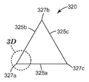
3A,
FIG. 3A is a schematic top view of an exemplary molded ceramic
3b,
FIG. 3B is a schematic side view of an exemplary molded ceramic
3C,
FIG. 3C is a sectional top view of plane 3-3 in FIG. 3B; FIG.
≪
Figure 3d is an enlarged view of the
<Fig. 4>
4 is an optical microscope photograph of the metal swab of Example 1 cutting ST52 steel under wet conditions.
While the drawings illustrate some embodiments of the invention, other embodiments are also contemplated, as will be seen in the discussion. The drawings may not be drawn at a constant rate. Throughout the drawings, like reference numerals may be used to denote like parts.
The polishing method according to the present invention uses a bonded abrasive cutting wheel comprising molded ceramic abrasive grains.
Referring now to FIG. 1, an exemplary bonded
Fig. 2 shows a cross-sectional view of the
Bonded abrasive cutting wheels are generally manufactured by a molding process. During molding, a binder precursor of a liquid organic material, a powdered inorganic material, a powdered organic material, or a combination thereof is mixed with the abrasive particles. In some cases, the liquid medium (resin or solvent) is first applied to the abrasive particles to wet the outer surface of the abrasive particles, after which the wetted particles are mixed with the powdered media. The bonded abrasive wheel according to the present invention can be produced by compression molding, injection molding or transfer molding. Molding may be carried out by hot or cold pressing or any suitable method known to those skilled in the art.
The binder typically comprises a glassy inorganic material (e.g., as in the case of a vitrified abrasive wheel), a metal, or an organic resin (such as in the case of a resin-bonded abrasive wheel) .
The glassy inorganic binder may be prepared from a mixture of different metal oxides. Examples of these metal oxide glassy binders include silica, alumina, calcia, iron oxide, titania, magnesia, sodium oxide, potassium oxide, lithium oxide, manganese oxide, boron oxide, phosphorus oxide and the like. Specific examples of vitreous binders include, by weight, for example, 47.61 wt% SiO 2 , 16.65 wt% Al 2 O 3 , 0.38 wt% Fe 2 O 3 , 0.35 wt% TiO 2 , 1.58 wt% CaO, 0.10 wt% MgO, 9.63 wt% Na 2 O, 2.86 wt% K 2 O, 1.77 wt% Li 2 O, 19.03 wt% B 2 O 3 , 0.02 wt% MnO 2 , and 0.22 % By weight of P 2 O 5 ; And 63 wt% SiO 2 , 12 wt% Al 2 O 3 , 1.2 wt% CaO, 6.3 wt% Na 2 O, 7.5 wt% K 2 O, and 10 wt% B 2 O 3 do. During the manufacture of the glassy bonded abrasive wheel, the glassy binder in powder form may be mixed with a temporary binder, typically an organic binder. The tritiated binder may also be formed, for example, from about 1% to 100% of the frit, but generally from about 20% to about 100% of the frit. Some examples of common materials used in frit binders include feldspar, borax, quartz, soda ash, zinc oxide, whiting, antimony trioxide, titanium dioxide, sodium silicon fluoride, flint, cryolite, boric acid, and combinations thereof. These materials are typically mixed together as powders, fired to fuse the mixture, and the fused mixture cooled. The cooled mixture is pulverized and selected as very fine powders, which are then used as frit binders. The temperature at which these frit junctions are completed depends on the chemical nature thereof, but may range from about 600 ° C to about 1800 ° C.
The binder holding the wheels together typically comprises from 5% to 50% by weight, more typically from 10% to 25% by weight, and even more typically from 12% to 24% by weight, based on the total weight of the bonded abrasive wheel, .
Examples of metal binders include tin, copper, aluminum, nickel, and combinations thereof.
The binder may comprise a cured organic binder resin, a filler, and a grinding aid. Phenolic resins are the most commonly used organic binder resins and can be used in both powder and liquid form. Although phenolic resins are widely used, the use of other organic binder resins including, for example, epoxy resins, polyimide resins, polyester resins, urea-formaldehyde resins, rubbers, shellac, Are within the scope of the invention. The organic binder may also be modified with other binders to enhance or modify the properties of the binder. The amount of organic binder resin may be, for example, from 15% to 100% by weight of the total weight of the binder.
Useful phenolic resins include novolac and resole phenolic resins. The novolak phenolic resin is acid-catalyzed and is characterized by a ratio of formaldehyde to phenol of less than 1, typically from 0.5: 1 to 0.8: 1. The resol phenol resin is alkali catalyzed and is characterized by a ratio of formaldehyde to phenol of at least 1, typically from 1: 1 to 3: 1. The novolak and resol phenolic resins can be chemically modified (e.g., by reaction with an epoxy compound), or they can be unmodified. Exemplary acidic catalysts suitable for curing phenolic resins include sulfuric acid, hydrochloric acid, phosphoric acid, oxalic acid, and p-toluenesulfonic acid. Suitable alkali catalysts for curing the phenolic resin include sodium hydroxide, barium hydroxide, potassium hydroxide, calcium hydroxide, organic amines, or sodium carbonate.
Phenolic resins are well known and readily available from commercial sources. Examples of commercially available novolac resins include DUREZ 1364, a two-step, powdered phenolic resin sold by Durez Corporation of Addison, Texas under the trade designation VARCUM 29302) or HEXION AD5534 RESIN sold by Hexion Specialty Chemicals, Inc. of Louisville, KY. Examples of commercially available resolephenol resins useful in the practice of the present invention include those sold under the trademark VARCUM by Durez Corporation (e.g., 29217, 29306, 29318, 29338, 29353); Those sold under the trademark AEROFENE by Ashland Chemical Co. of Bartow, Fla. (E.g., AEROPEN 295); And those sold under the trademark " PHENOLITE " by Kangnam Chemical Company Ltd. of Seoul, Korea (e.g., phenolite TD-2207).
The curing temperature of the organic binder precursor will vary depending on the material chosen and the wheel design. The choice of suitable conditions is within the ability of one skilled in the art. Exemplary conditions for the phenolic binder include an applied pressure of about 224 kg / cm < 2 > (20 ton / 4 inch diameter) at room temperature accompanied by heating the temperature to a maximum of about 190 DEG C for a period of time sufficient to cure the organic binder precursor can do.
In some embodiments, the bonded abrasive wheel comprises from about 10% to about 80% by weight of the ceramic abrasive particles formed, based on the total weight of the binder and abrasive particles; Typically from 30% to 60% by weight, and more typically from 40% to 60% by weight.
Molded ceramic abrasive particles composed of crystals of alpha alumina, magnesium alumina spinel, and rare earth hexagonal aluminate are described, for example, in U.S. Patent No. 5,213,591 (Celikkaya et al.), Can be prepared using sol-gel precursor alpha alumina particles according to the methods described in Application No. 2009/0165394 A1 (Culler et al.) And 2009/0169816 Al (Erickson et al.).
Alpha alumina-based shaped ceramic abrasive particles can be prepared according to a multistage process. In summary, the process comprises preparing a seeded or non-seeded sol-gel alpha alpha alumina precursor dispersion that can be converted to alpha alumina, and dispersing the one or more Forming a precursor-molded ceramic abrasive grain by removing the precursor-molded ceramic abrasive grains from the mold cavity, calcining the precursor-molded ceramic abrasive grains, calcining the calcined, Forming precursor-molded ceramic abrasive grains, and then sintering the calcined, precursor-molded ceramic abrasive grains to form the shaped ceramic abrasive grains. Now, this process will be described in more detail.
The first process step entails providing a seeded or non-seeded dispersion of an alpha alumina precursor that can be converted to alpha alumina. Alpha alumina precursor dispersions often include liquids that are volatile components. In one embodiment, the volatile component is water. The dispersion should contain a sufficient amount of liquid to sufficiently fill the mold cavity and to make the viscosity of the dispersion sufficiently low so as to be able to replicate the mold surface but not so much that it would be prohibitively expensive to later remove the liquid from the mold cavity . In one embodiment, the alpha alumina precursor dispersion comprises from 2 wt% to 90 wt% of particles that can be converted to alpha alumina, such as particles of aluminum oxide monohydrate (boehmite), at least 10 wt%, or 50 To 70% by weight, or 50 to 60% by weight of water. Conversely, the alpha alumina precursor dispersion, in some embodiments, contains from 30 to 50 wt%, or from 40 to 50 wt% solids.
Aluminum oxide hydrates other than boehmite may also be used. The boehmite can be manufactured or purchased by known techniques. Examples of commercially available boehmite include the trademarks " DISPERAL ", and " DISPAL ", all available from Sasol North America, Inc., Houston, Tex. , Or " HiQ-40 " available from BASF Corporation of Flumam Park, New Jersey. These aluminum oxide monohydrates are relatively pure; That is, they contain relatively small hydrate phases, if at all other than monohydrates, and have a large surface area.
The physical properties of the resulting shaped ceramic abrasive particles will generally depend on the type of material used in the alpha alumina precursor dispersion. In one embodiment, the alpha alumina precursor dispersion is in a gel state. As used herein, a " gel " is a solid three-dimensional mesh structure that is dispersed in a liquid.
The alpha alumina precursor dispersion may contain a reforming additive or a precursor of the reforming additive. The modifying additive can serve to improve some desirable properties of the abrasive grain or to enhance the effect of the subsequent sintering step. The precursor of the modifying or modifying additive may be in the form of a particle, a particle suspension, a sol or a soluble salt, typically in the form of a water-soluble salt. These are typically composed of metal containing compounds and may be selected from the group consisting of magnesium, zinc, iron, silicon, cobalt, nickel, zirconium, hafnium, chromium, yttrium, praseodymium, samarium, ytterbium, neodymium, lanthanum, gadolinium, cerium, dysprosium, erbium , Titanium, zirconium, and mixtures thereof. The specific concentration of these additives that may be present in the alpha alumina precursor dispersion may vary according to those skilled in the art.
Typically, introducing a precursor of a modifying or modifying additive will result in a gel of the alpha alumina precursor dispersion. The alpha alumina precursor dispersion can also be guided to the gel by application of heat over a period of time. The alpha alumina precursor dispersion may also contain a nucleating agent (seeding) to enhance the conversion of hydrated or calcined aluminum oxide to alpha alumina. Suitable nucleating agents for this disclosure include fine particles of alpha alumina, alpha iron oxide or its precursor, titanium oxide and titanate, chromium oxide, or other materials that will be the nucleus of the transformation. If used, the amount of nucleating agent should be sufficient to effect conversion of alpha alumina. The nucleation of these alpha-alumina precursor dispersions is described in Schwabel, U.S. Patent No. 4,744,802.
A peptizing agent may be added to the alpha alumina precursor dispersion to prepare a more stable hydrosol or colloidal alpha alumina precursor dispersion. Suitable peptizing agents are monoprotic acid or acid compounds such as acetic acid, hydrochloric acid, formic acid and nitric acid. Multiprotic acid may also be used, but this can make it difficult to rapidly gel the alpha alpha alumina precursor dispersion to handle or introduce additional components into it. Some commercial sources of boehmite contain an acid titer (e. G., Absorbed formic acid or nitric acid) to help form a stable alpha alumina precursor dispersion.
The alpha alumina precursor dispersion can be formed by any suitable means, for example by simply mixing water containing a peptizing agent with aluminum oxide monohydrate, or by forming an aluminum oxide monohydrate slurry to which the peptizing agent is added have.
Defoaming agents or other suitable chemicals may be added to reduce the tendency for bubbles to form or contain air during mixing. If desired, additional chemicals such as wetting agents, alcohols or coupling agents may be added. Alpha alumina abrasive grains may contain silica and iron oxide as disclosed in U. S. Patent No. 5,645, 619 to Erickson et al. Alpha alumina abrasive grains may contain zirconia as disclosed in Larmie, U.S. Patent No. 5,551,963. Alternatively, the alpha alumina abrasive grains may have microstructures or additives as disclosed in U.S. Patent No. 6,277,161 to Castro.
The second process step comprises providing a mold having at least one mold cavity, preferably a plurality of cavities. The mold may have a generally flat bottom surface and a plurality of mold cavities. A plurality of cavities may be formed in the manufacturing tool. The production tool can be a belt, a sheet, a continuous web, a coating roll such as a rotogravure roll, a sleeve mounted on a coating roll, or a die. In one embodiment, the manufacturing tool comprises a polymeric material. Examples of suitable polymeric materials include polymers such as polyesters, polycarbonates, poly (ether sulfone), poly (methyl methacrylate), polyurethane, polyvinyl chloride, polyolefin, polystyrene, polypropylene, polyethylene, A thermoplastic material, or a thermoset material. In one embodiment, the entire tool is made of a polymeric material or a thermoplastic material. In another embodiment, the surface of the tool in contact with the sol-gel during drying, such as the surface of the plurality of cavities, comprises a polymeric or thermoplastic material, and other parts of the tool may be made of other materials. For example, a suitable polymeric coating can be applied to the metal tool to change the surface tension properties.
The polymeric or thermoplastic tool may be replicated from the metal master tool. The master tool will have the reverse phase pattern required for the production tool. The master tool can be manufactured in the same manner as the production tool. In one embodiment, the master tool is made of metal, for example nickel, and diamond-turned. The polymeric sheet material can be heated together with the master tool, and by pressing the two together, the polymeric material is embossed with the master tool pattern. The polymeric or thermoplastic material can also be extruded or cast onto a master tool and then compressed. The thermoplastic material is cooled to solidify to produce the production tool. If thermoplastic manufacturing tools are used, care should be taken not to limit the service life by deforming the thermoplastic tool with excessive heat. More information about the design and fabrication of manufacturing tools or master tools can be found in U.S. Pat. No. 5,152,917 (Pieper et al.); U.S. Patent No. 5,435,816 (Spurgeon et al.); Can be found in U.S. Patent No. 5,672,097 (Hoopman et al), U.S. Patent No. 5,946,991 (Hoffman et al.), U.S. Patent No. 5,975,987 (Hoffman et al.), And U.S. Patent No. 6,129,540 have.
Access to the cavity can be made from the top surface of the mold or from the opening in the bottom surface. In some cases, the cavity may extend over the entire thickness of the mold. Alternatively, the cavity may extend for only a portion of the thickness of the mold. In one embodiment, the top surface is substantially parallel to the bottom surface of the mold where the cavity has a substantially uniform depth. At least one side of the mold, i.e. the side on which the cavity is formed, may remain exposed to the ambient atmosphere during the step of removing the volatile components.
The cavity has a specific three-dimensional shape to produce molded ceramic abrasive particles. The depth dimension is equal to the vertical distance from the top surface to the lowest point on the bottom surface. The depth of a given cavity may be uniform or vary along its length and / or width. The cavities of a given mold may be of the same shape or of different shapes.
The third process step includes filling the cavity of the mold with an alpha alumina precursor dispersion (e.g., by the prior art). In some embodiments, a knife roll coater or vacuum slot die coater may be used. A mold release agent may be used to assist in removing particles from the mold, if desired. Typical mold release agents include oils such as peanut oil or mineral oil, fish oil, silicone, polytetrafluoroethylene, zinc stearate, and graphite. Generally, when a mold release agent is required, about 0.1 mg / in 2 to about 3.0 mg / in 2 , or about 0.02 mg / in 2 per unit area of the mold, 2) to about 0.78 ㎎ / ㎠ (5.0 ㎎ / in 2) so that the mold release agent is present, the sol-is applied to the mold in a liquid such as water or alcohol to the surface of the manufacturing tool in contact with the gel mold release agents, for example peanut oil. In some embodiments, the top surface of the mold is coated with an alpha alumina precursor dispersion. The alpha alumina precursor dispersion can be pumped onto the upper surface.
Next, a scraper or leveler bar can be used to fully push the alpha alumina precursor dispersion into the cavity of the mold. The remainder of the alpha alumina precursor dispersion that has not entered the cavity can be removed from the upper surface of the mold and recycled. In some embodiments, a small portion of the alpha alumina precursor dispersion may remain on the top surface, and in other embodiments, there is substantially no dispersion on the top surface. The pressure exerted by the scraper or leveler bar is typically less than 0.7 MPa (100 psi), less than 0.3 MPa (50 psi), or even less than 69 kPa (10 psi). In some embodiments, the exposed surface of the alpha alumina precursor dispersion does not extend substantially over the top surface to ensure uniformity in thickness of the resulting shaped ceramic abrasive particles.
The fourth process step includes removing volatile components and drying the dispersion. Preferably, the volatile component is removed by a rapid evaporation rate. In some embodiments, removal of volatile components by evaporation occurs at temperatures above the boiling point of the volatile components. The upper limit for the drying temperature often depends on the material of the mold. For polypropylene tools, this temperature should be below the melting point of the plastic. In one embodiment, for aqueous dispersions and polypropylene molds of about 40 to 50% solids, the drying temperature is from about 90 캜 to about 165 캜, or from about 105 캜 to about 150 캜, or from about 105 캜 to about 120 캜 Lt; / RTI > Higher temperatures may lead to improved manufacturing speeds, but may also lead to degradation of the polypropylene tool which limits its service life as a mold.
The fifth process step includes removing the resulting precursor molded ceramic abrasive particles from the mold cavity. Precursor molded ceramic abrasive grains can be removed from the cavities by using alone or in combination the following processes on the mold: gravity, vibration, ultrasonic vibration, vacuum, or compressed air to remove particles from the mold cavity.
The precursor abrasive particles may be further dried outside the mold. If the alpha alumina precursor dispersion is dried to the desired level in the mold, this additional drying step is not necessary. However, in some cases it may be economical to use this additional drying step to minimize the time that the alpha alumina precursor dispersion is in the mold. Typically, the precursor molded ceramic abrasive particles will be dried at a temperature of from 50 ° C to 160 ° C, or from 120 ° C to 150 ° C, for 10 minutes to 480 minutes, or from 120 minutes to 400 minutes.
The sixth process step includes calcining the precursor molded ceramic abrasive particles. During calcination, essentially all volatile materials are removed and various components present in the alpha alumina precursor dispersion are converted to metal oxides. The precursor molded ceramic abrasive particles are generally heated to a temperature of 400 ° C to 800 ° C and remain within this temperature range until free water and any combined volatile material in excess of 90% by weight are removed . In an optional step, it may be desirable to introduce the conditioning additive by an impregnation process. A water soluble salt may be introduced into the pores of the precursor molded ceramic abrasive particles calcined by impregnation. Thereafter, the precursor-molded ceramic abrasive particles are again prebaked. This option is further described in U.S. Patent No. 5,164,348 (Wood).
The seventh process step includes sintering the calcined precursor molded ceramic abrasive particles to form alpha alumina particles. Prior to sintering, the calcined precursor molded ceramic abrasive particles are not fully densified and therefore lack the hardness required for use as molded ceramic abrasive particles. The sintering is performed by heating the calcined precursor shaped ceramic abrasive particles to a temperature of between 1,000 DEG C and 1,650 DEG C until substantially all of the alpha alumina monohydrate (or equivalent) is converted to alpha alumina and the porosity is reduced to less than 15 vol% Is maintained within this temperature range. The length of time that the calcined precursor ceramic abrasive particles must be exposed to the sintering temperature to achieve this level of conversion will vary depending on various factors, but is typically from 5 seconds to 48 hours.
The duration of the sintering step may be in the range of, for example, 1 minute to 90 minutes. After sintering, the shaped ceramic abrasive grains may have a Vickers hardness of 10 gigapascals (GPa), 16 GPa, 18 GPa, 20 GPa, or more.
Other steps may be used to modify the process described above, such as rapidly heating the material from the calcination temperature to the sintering temperature and centrifuging the alpha alumina precursor dispersion to remove sludge and / or waste. In addition, this process can be modified by combining two or more of the process steps as needed. Conventional process steps that can be used to modify the process of the present invention are more fully described in US Patent No. 4,314,827 to Leitheiser.
More information relating to methods for making molded ceramic abrasive particles is disclosed in co-pending U.S. Published Application No. 2009/0165394 A1 (Cooler et al.).
Although there are no specific limitations on the shape of the shaped ceramic abrasive particles, the abrasive particles are preferably formed using a mold, for example, by molding precursor particles comprising a ceramic precursor material (e.g., a boehmite sol-gel) And then sintered to form a predetermined shape. The shaped ceramic abrasive particles may be shaped, for example, as columnar pyramids, truncated pyramids (e.g., truncated triangular pyramids), and / or some other regular or irregular polygons. The abrasive particles may comprise abrasive agglomerates formed by one kind of abrasive particles or two or more kinds of abrasives, or a polishing mixture of two or more kinds of abrasives. In some embodiments, the precisely shaped molded ceramic abrasive particles within the individually shaped ceramic abrasive particles have a shape that is substantially the shape of a portion of the cavity of the mold or fabric tool in which the particle precursor is dried prior to selective calcination and sintering .
Figures 3A and 3B show an exemplary usefully
In some embodiments, the shaped ceramic abrasive particles may have a radius of curvature along the side edges connecting the base and top of the molded ceramic abrasive particles of 50 micrometers or less. The radius of curvature may be measured, for example, using a CLEMEX VISION PE image analysis program (Clemex Technologies, Inc., Longgay, Technologies, Inc.), or from any other polished cross-section taken between the top surface and the bottom surface using any other suitable image analysis software / facility. The radius of curvature for each point of the shaped abrasive particles can be determined by defining three points at the tip of each point when viewed in cross-section (e.g., at 100X magnification). The first point is located at the beginning of the curve of the tip with a transition from the straight edge to the beginning of the curve, the second point is located at the apex of the tip, and the third point is the transition from the curved tip to the straight edge . The image analysis software then calculates an arc defined by the three points (the start point, midpoint and end point of the curve) and the radius of curvature. The radius of curvature for at least 30 vertices is measured and averaged to determine the average tip radius.
The shaped ceramic abrasive grains used in the present invention are typically machined using tools such as diamond tools that provide a higher feature definition than other manufacturing alternatives such as stamping or punching, Mold) cutting. Typically, the cavity in the tool surface has a planar surface that meets along a sharp edge and forms the top and sides of the truncated pyramid. The resulting shaped ceramic abrasive grains have respective nominal average shapes corresponding to the geometry of the cavity (e.g., the truncated pyramid) in the tool surface, but deformations (e. G., Any deformations) from the nominal averaged shape And the shaped ceramic abrasive particles exhibiting such deformation are included in the definition of the shaped ceramic abrasive particles as used herein.
In some embodiments, the base and top of the shaped ceramic abrasive particles are substantially parallel, thus forming a prism or truncated pyramid (as shown in Figures 3A and 3B), although this is not a requirement. As shown, the
As used herein to refer to a shaped ceramic abrasive particle, the term " length " refers to the maximum dimension of the shaped abrasive particles. &Quot; Width " refers to the maximum dimension of the shaped abrasive particles perpendicular to the length. The term " thickness " or " height " refers to the dimensions of a shaped abrasive particle perpendicular to the length and width.
The shaped ceramic abrasive particles are typically selected to have a length of from 0.1 micron to 1600 microns, more typically from 10 microns to about 1000 microns, and even more typically from 150 microns to 800 microns, although other lengths may also be used. In some embodiments, the length can be expressed as part of the thickness of the bonded abrasive wheel in which it is received. For example, the shaped abrasive particles may have a length greater than half the thickness of the bonded abrasive wheel. In some embodiments, the length may be greater than the thickness of the bonded abrasive cutting wheel.
The shaped ceramic abrasive grains may be formed to have a width typically in the range of 0.001 mm to 26 mm, more typically 0.1 mm to 10 mm, and more typically 0.5 mm to 5 mm, although other lengths may also be used Is selected.
The shaped ceramic abrasive particles are typically selected to have a thickness in the range of 0.005 mm to 10 mm, more typically 0.2 mm to 1.2 mm.
In some embodiments, the shaped ceramic abrasive particles may have an aspect ratio (length to thickness) of at least 2, 3, 4, 5, 6, or more.
The surface coating on the shaped ceramic abrasive grains can be used to improve adhesion between the binder in the abrasive article and the shaped ceramic abrasive grains or can be used to assist electrostatic deposition of the shaped ceramic abrasive grains. In one embodiment, a surface coating may be used as described in U.S. Patent No. 5,352,254 (Selicaya) with an amount of surface coating of from 0.1% to 2% based on the weight of the shaped abrasive grains. Such surface coatings are described in U.S. Patent No. 5,213,591 (Sirika et al.); 5,011,508 (Wald et al.); 1,910,444 (Nicholson); 3,041,156 (Rowse et al.); 5,009, 675 (Kunz et al.); 5,085,671 (Martin et al.); 4,997, 461 (Markhoff-Matheny et al.), And 5,042,991 (Kunz et al.). In addition, the surface coating can prevent the formed abrasive particles from being capped. Capping is a term describing the phenomenon that metal particles from a workpiece being worn are fused to the upper part of a molded ceramic abrasive grain. Surface coatings that perform this function are known to those skilled in the art.
The bonded abrasive wheel may further comprise additional abrasive particles that can be ground (i.e., abrasive particles corresponding to the abrasive industry specific nominal class or combination thereof and not formed from the fracture of the shaped ceramic abrasive particles). The ground abrasive grains, although not necessarily required, are typically formed with finer size grades or grades (e.g., where a plurality of size grades are used) than the shaped ceramic abrasive grains.
Useful additional abrasive particles include, for example, fused aluminum oxide such as those available commercially from 3M Company, St. Paul, Minn., USA, under the trade designation CERAMIC ABRASIVE GRAIN, heat treated aluminum oxide, Titanium oxide, aluminum oxide, aluminum oxide, aluminum oxide, aluminum oxide, aluminum oxide, aluminum oxide, aluminum oxide, Zirconia, titania, silicate, tin oxide, silica (e.g., quartz, glass beads, glass bubbles, glass beads, And glass fibers), silicates (e.g., talc, clays (e.g. montmorillonite), feldspar, mica, calcium silicate, Calcium metasilicate, sodium aluminosilicate, sodium silicate), flint, emery, and combinations thereof. Examples of sol-gel derived abrasive particles include U.S. Pat. No. 4,314,827 (Lateau et al.), U.S. Pat. No. 4,623,364 (Cottringer et al.); U.S. Patent No. 4,744,802 (Schwabel); U.S. Patent No. 4,770,671 (Monroe)); And U.S. Patent No. 4,881,951 (Munro et al.). It is also contemplated that abrasive particles may include abrasive agglomerates such as those described in, for example, U.S. Patent No. 4,652,275 (Bloecher et al.) Or U.S. Patent No. 4,799,939 (Brocheer et al.) . In some embodiments, the abrasive particles are surface-treated with a coupling agent (e.g., an organosilane coupling agent) or other physical treatment agent (e. G., Iron oxide or titanium oxide) to improve adhesion of the abrasive particles to the binder. . The abrasive particles may be treated prior to combining them as a binder, or the abrasive particles may be surface treated at their original position by including a coupling agent for the binder.
Typically, conventional comminuted abrasive grains are sized independently according to a particular nominal grade, which is the abrasive industry name. Exemplary abrasive industry certified grade standards include: ANSI (American National Standards Institute); FEPA (Federation of European Producers of Abrasives); and JIS (Japanese Industrial Standard) ≪ / RTI > The ANSI rating designations (i.e., the nominal ratings specified) are, for example: ANSI 4, ANSI 6, ANSI 8, ANSI 16,
More typically, the ground aluminum oxide particles and the non-seeded sol-gel derived alumina-based abrasive particles are independently selected from ANSI 60 and 80, or FEPA F16, F20, F24, F30, F36, F46, F54 and F60 grades Size is standardized. According to an embodiment of the present invention, the average diameter of the abrasive particles may be in the range of 260 microns to 1400 microns according to FEPA grades F60 to F24.
Alternatively, the shaped ceramic abrasive particles may be subjected to a nominal sorting process using an American Standard Test Specimen according to ASTM E-11 " Standard Specification for Wire Cloth and Sieves for Testing Purposes " (Nominal screened grade). ASTM E-11 specifies the requirements for the design and construction of test bodies using a knitted mesh media mounted on the frame for the classification of materials according to the specified particle size. A typical designation can be represented as -18 + 20, which means that the molded ceramic abrasive particles pass through a test body that meets the ASTM E-11 specification for the 18th sieve and meet the ASTM E-11 specification for the 20th sieve It means that it is caught and held by the test body. In one embodiment, the shaped ceramic abrasive particles have a particle size that allows most of the particles to pass through an 18 mesh test body and be held on a 20, 25, 30, 35, 40, 45, or 50 mesh test body . In various embodiments, the shaped ceramic abrasive particles are: -18 + 20, -20 / +25, -25 + 30, -30 +35, -35 + 40,5-40 +45, -45 + 50 + 60, -60 + 70, -70 / + 80, -80 + 100, -100 + 120, -120 + 140, -140 + 170, -170 + 200, -200 + -270 + 325, -325 + 400, -400 + 450, -450 + 500, or -500 + 635. Alternatively, for example, a custom mesh size such as -90 + 100 may be used. The total amount of abrasive particles (bonded ceramic abrasive particles plus any other abrasive particles) in the bonded abrasive wheel is preferably in the amount of 35% to 80% by weight, based on the total weight of the bonded abrasive wheel.
The abrasive particles may be uniformly or non-uniformly distributed, for example, over the bonded abrasive article. For example, abrasive grains can be concentrated towards the outer edge (i.e., the periphery) of the cutting wheel. The central portion may contain a smaller amount of abrasive particles. In another variation, the first abrasive grain may be on the side of the wheel with different abrasive grains at the center. However, typically all of the abrasive particles are homogeneously distributed among one another because the wheels are easier to manufacture and the cutting effect is optimized when the two types of abrasive particles are placed close together.
The bonded abrasive wheel is typically used in an amount of from 1 wt% to 25 wt%, more typically from 10 wt% to 20 wt%, based on the weight range requirements of the other components to be matched, for example, polytetrafluoroethylene Particles, graphite, molybdenum sulfide, cryolite, sodium chloride, potassium chloride, FeS2 (iron disulfide), zinc sulfide or KBF4. A grinding aid is usually added to improve the cutting characteristics of the cutting wheel, which results in a temperature reduction of the cutting interface. The grinding aid may be in the form of a single particle or an agglomerate of grinding aid particles. Examples of finely shaped grinding aid particles are taught in U.S. Patent Publication No. 2002 / 0026752A1 (Cooler et al.).
In some embodiments, the binder contains a plasticizer, such as is available, for example, as SANTICIZER 154 PLASTICIZER from UNIVAR USA, Chicago, Illinois, USA.
The bonded abrasive wheel may contain additional components such as, for example, filler particles, provided that the weight range requirements of the other components are met. The filler particles may be added to occupy space and / or provide porosity. The porosity may allow the bonded abrasive wheel to be used to expose new or unworn abrasive particles or to discharge abraded abrasive particles. Examples of fillers include bubbles and beads (e.g., glass, ceramic (alumina), clay, polymer, metal), calcite, metal carbonate, gypsum, marble, limestone, flint, silica, silicates , Metal sulfates, metal sulfides, metal oxides, metals (such as tin or aluminum), and metal sulfides as well as metal halide compounds. The filler can assist in cutting performance and performance of the cutting wheel to reduce friction, wear and apparent temperature in the grinding zone. The filler may be used alone or in combination within a range of about 1 wt% to 60 wt%, preferably 20 wt% to 40 wt%, based on the total weight of the binder. Particle sizes that can vary depending on the type of filler typically range in size from 1 micron to 150 microns.
The bonded abrasive wheel may have porosity in any range, for example, from less than 1 volume% to 50 volume%, typically from 1 volume% to 40 volume%.
The bonded abrasive wheel may be manufactured according to any suitable method. In one suitable method, the non-seeded sol-gel derived alumina-based abrasive particles are coated with a coupling agent prior to mixing with the curable resol phenolic resin. The amount of coupling agent is generally selected to be present in an amount of 0.1 to 0.3 parts per 50 to 84 parts of abrasive grains, although amounts outside this range may also be used. Liquid resin as well as curable novolak phenolic resin and cryolite were added to the resulting mixture. The mixture was pressurized at room or elevated temperature into a mold (e.g., an applied pressure of 224 kg / cm 2 (20 ton / 4 inch diameter)). The molded wheel is then cured by heating at a temperature of up to about 185 DEG C for a time sufficient to cure the curable phenolic resin.
Coupling agents are well known to those skilled in the art of polishing. Examples of coupling agents include trialkoxy silanes (e.g., gamma-aminopropyl triethoxy silane), titanates, and zirconates.
A useful bonded abrasive wheel is, for example, a cutting wheel and abrasive industry type 27 (such as in the American National Standards Institute standard ANSI B7.1-2000 (2000) 1.4.14 section) Center-recessed grinding and cutting wheels.
The optional center hole may be used to attach the abrasive wheel bonded to a power tool including a stationary tool. In present, the central hole, which may be round or some other shape, is typically 5 mm to 25 mm or larger in cross-sectional diameter, although other sizes may be used. The center hole is typically about one-tenth of the diameter of the abrasive wheel bonded. The optional center hole can be reinforced, for example by a metal flange. In some cases, the abrasive wheel may have a steel core including an outer bonded abrasive ring.
In some embodiments, the bonded abrasive wheel is at least 150 millimeters (mm), 200 mm, 230 mm, 260 mm, 350 mm, 400 mm, 500 mm, 800 mm, 1000 mm, 1200 mm, 1500 mm, It can even have a diameter of at least 2500 mm.
Alternatively, the bonded abrasive wheel used in the method according to the invention, and in particular the cutting wheel, may be arranged on the main surface of one or both of the bonded abrasive wheels, for example, (E. G., Paper, nonwoven, woven or knit material) to reinforce the bonded abrasive wheel. ≪ / RTI > Examples of reinforcing materials include knitted or woven fabrics or scrims. The fibers in the reinforcing material can be made from glass fibers (e.g., fiberglass), carbon fibers, and organic fibers, such as polyamide, polyester, or polyimide. In some cases, it may be desirable to include reinforcing staple fibers in the bonding medium such that the fibers are evenly distributed throughout the cutting wheel.
The reinforcing fibers may be added to the bonded abrasive wheel to improve the stability and / or safety of the bonded abrasive wheel. The reinforcing fibers may comprise a glass fiber impregnated with a resin, preferably a phenolic resin. The position can be on the outside of both sides and / or in the interior part of the wheel. The number of reinforcement parts depends on the application of the bonded abrasive wheel.
A high-power stationary device may be suitable for the practice of the present invention. Examples include Danieli & Cia Officine Meccaniche SPA from Butyria, Italy; Braun Maschinenfabrik of Boclavabru, Austria; And Siemens VAI Metals Technologies S. (Pomini), Mannate, Italy, all of which are incorporated by reference. The motor can generally be driven electrically, hydraulically, or pneumatically at a rate of about 1000 to 50000 revolutions per minute (rpm). In some embodiments, the circumferential work surface of the bonded abrasive wheel rotates at a rate of at least 30 meters per second (m / sec), at least 60 meters per second, or even at least 80 meters per second.
The method of grinding the workpiece according to the invention can be carried out, for example, dry or wet and / or hot or cold, as desired. During the wet process, the bonded abrasive wheel is used with water, an oil-based lubricant, or a water-based lubricant. The bonded abrasive wheel according to the present invention can be used, for example, in a variety of workpiece materials, such as high carbon steel or low carbon steel sheets or bar stock and more heterogeneous metals (e.g., stainless steel or titanium) (E. G., Mild steel, low alloy steels, or cast iron). ≪ / RTI >
Preferably, the method according to the invention can be carried out in excess of the conventional cutting speed. For example, in some embodiments, the workpiece and the rotationally bonded abrasive wheel may be at least 20 centimeters squared per second (cm2 / sec), 45cm2 / sec, 50cm2 / sec, 50cm2 / sec, or even at least 60cm2 / sec Can be pressed against each other to achieve the cutting speed.
The swabs produced from the method according to the present invention include filament swabs and optionally other non-filament components. That is, the filament swab may represent the total amount of swabs produced, or more typically less than that. Within the aggregate, the filament swab may be similar to a steel wool. In some embodiments, at least a portion of the filament swab may have a length of at least 3 millimeters (mm), at least 10 mm, at least 15 mm, at least 20 mm, or even at least 25 mm. In some embodiments, at least some of the filament swabs may have an aspect ratio (length divided by width) of at least 5, 10, 20, 50, or even 100.
Whatever the theory, the cutting performance of the bonded abrasive article useful in the present invention may be due to self-sharpening fracturing of the shaped ceramic abrasive particles during use.
In addition, in the practice of the present invention, the G-ratio is typically used in comparable conventional bonded abrasive wheels having only a ground abrasive grain of the same composition, instead of a molded ceramic abrasive grain, resulting in a longer service life . In some embodiments, the G-ratio is at least 2, 2.5, or even 3.
Optional embodiments of the present disclosure
In a first embodiment, the present invention provides a method of polishing a workpiece,
Providing a fixed rotatively bonded abrasive wheel having a diameter of at least 150 millimeters; the bonded abrasive wheel comprising molded ceramic abrasive grains retained in the binder; And
Contacting the metallic workpiece with a rotatably bonded abrasive wheel so that the workpiece is polished while simultaneously forming a metallic swab; the metallic workpiece has a bulk temperature of less than 500 DEG C and wherein at least 20 weight percent of the metallic swarf has a filament metallicity Swap.
In a second embodiment, the present invention provides a method according to the first embodiment, wherein at least 20% by weight of the metallic swarf is a filament metallic swarf having a length of at least 10 millimeters.
In a third embodiment, the present invention provides a method according to the first or second embodiment, wherein the rotationally bonded abrasive wheel further comprises ground abrasive particles.
In a fourth embodiment, the present invention provides a method according to any one of the first to third embodiments, wherein the binder comprises a cured organic binder resin.
In a fifth embodiment, the present invention provides a method according to any one of the first to fourth embodiments, wherein the rotationally bonded abrasive wheel has a diameter of 350 millimeters or more.
In a sixth embodiment, the present invention provides a method according to any one of the first to fifth embodiments wherein the workpiece and the rotating abrasive wheel are pressed against each other to achieve a cutting speed of at least 20 cm2 / s do.
In a seventh embodiment, the present invention provides a method according to any one of the first to sixth embodiments wherein the workpiece and the rotating abrasive wheel are pressed against each other to achieve a cutting speed of at least 40 cm2 / sec do.
In an eighth embodiment, the present invention provides a method according to any one of the first to seventh embodiments, wherein the molded ceramic abrasive particles are precisely molded.
In a ninth embodiment, the present invention provides a method according to any one of the first to eighth embodiments, wherein the molded ceramic abrasive particles include a truncated triangular pyramid.
In a tenth embodiment, the present invention provides a method according to any one of the first to ninth embodiments, wherein the molded ceramic abrasive particles comprise alpha-alumina.
In an eleventh embodiment, the present invention provides a method according to any one of the first to tenth embodiments, wherein the workpiece includes steel.
In a twelfth embodiment, the present invention provides a method according to any one of the first to eleventh embodiments, wherein the rotationally bonded abrasive wheel has a diameter of 1000 millimeters or more.
In a thirteenth embodiment, the present invention provides a method according to any one of the first to twelfth embodiments, wherein the rotationally bonded abrasive wheel has a peripheral working surface rotating at a speed of at least 20 meters per second.
In a fourteenth embodiment, the present invention provides a method according to any one of the first to thirteenth embodiments, wherein the G-ratio in cold cutting conditions is three or more.
The objects and advantages of the present invention are further illustrated by the following non-limiting examples, but the specific materials and amounts thereof as well as other conditions or details recited in these examples are to be construed as unduly limiting the present invention .
Example
Unless otherwise indicated, all parts, percentages, ratios, etc. in the remainder of the examples and the specification are by weight. The abbreviation " pbw " refers to parts by weight.
Preparation of REO-doped shaped ceramic abrasive grains (SAP1)
A sample of boehmite sol-gel was prepared using the following method: Dispersal available aluminum oxide monohydrate powder (1600 parts) from Sasol North America, Inc. was mixed with water (2400 parts) and 70% Was dispersed by high shear mixing in a solution containing aqueous nitric acid (72 parts) for 11 minutes. The resulting sol-gel was aged for at least 1 hour before coating. The sol-gel was pushed into a manufacturing tool with a triangularly shaped mold cavity of the following dimensions: 2.79 mm x 0.762 mm, 98 [deg.] Inclination.
The sol-gel was pushed into the cavity with a putty knife to fully fill the opening of the manufacturing tool. A mold release agent, about 0.08 mg / in 2 (0.5 mg / cm 2) of peanut oil was applied to the manufacturing tool using 1% peanut oil in methanol as applied to the manufacturing tool. Extra methanol was removed by placing a sheet of the manufacturing tool in an air convection oven at 45 占 폚 for 5 minutes. The sol-gel coated manufacturing tool was placed in an air convection oven at 45 캜 for at least 45 minutes for drying. The manufacturing tool was passed over an ultrasonic horn to remove precursor molded ceramic abrasive particles from the manufacturing tool. The precursor molded ceramic abrasive particles were calcined at approximately 650 캜 and then saturated with mixed nitrate solutions (MgO, Y 2 O 3 , CoO and La 2 O 3) .
The shaped ceramic abrasive grains were treated to improve the electrostatic application of the shaped ceramic abrasive grains in a manner similar to that used to produce ground abrasive grains as disclosed in U.S. Patent No. 5,352,254 (Sirika). The calcined molding ceramic abrasive grain precursor was impregnated with a rare earth oxide (REO) solution of the alternative containing 1.4% of MgO, 1.7% of Y2O 3, the 5.7% La2O 3 and CoO of 0.07%. A solution of 1.4 grams of HYDRAL COAT 5 powder (average particle size of about 0.5 micron), available from Almatis, Pittsburgh, Pa., In 70 grams of REO solution was stirred in an open beaker . Thereafter, approximately 100 grams of calcined precursor molded ceramic abrasive grains were impregnated with 71.4 grams of Hydralcoat 5 powder dispersion in REO solution. After removing the excess nitrate solution and allowing the saturated precursor-molded ceramic abrasive to dry, the particles were again calcined at 650 ° C and sintered at approximately 1400 ° C. Both the calcination and sintering steps were performed using a rotary tube kiln. The resulting composition contained an alumina composition containing 1 wt% MgO, 1.2 wt% Y 2 O 3 , 4 wt% La 2 O 3 , and 0.05 wt% CoO and traces of TiO 2 , SiO 2 , and CaO . The resulting shaped ceramic abrasive particles had the following characteristics: average particle length = 1.384 mm (standard deviation = 0.055 mm), mean particle thickness = 0.229 mm (standard deviation = 0.026 mm), average particle aspect ratio = 6.0, The average curvature radius of the edge is 12.71 microns (standard deviation = 7.44 microns).
Example 1
The following composition was prepared: SAP1 (70.8 pbw) of the shaped ceramic abrasive grains was mixed with PREFERE 825174 liquid phenolic resin (5.05 pbw) from Dynea OY, Helsinki, Finland. The mixture was mixed for 5 minutes and the grain was covered with liquid resin.
The binder mixture was prepared by combining the following: 5.9 pbw of prefere 828528 phenolic powder resin from Daina Ouai; Germany's Neue - Ulm's Jette-West-Chamie GmbH
A glass fiber knit reinforcement having a basis weight of 200 g / cm < 2 > to 400 g / cm < 2 > The mold was then filled with 1157 grams of the above mixture. A second portion of the reinforcing scrim was placed on the upper side of the mixture. The mold was sealed and placed under a pressure of 500 metric tons for several seconds. The compressed wheel was transferred to a metal plate and placed in an oven for curing for up to 180 ° C for up to 28 hours. The resulting wheel had a thickness of 4.4 mm, a diameter of 400 mm and a center hole of 40 mm diameter.
After curing, the resulting wheel was tested for cutting. Hulse metal in Camem, Germany, operating at a peripheral work surface speed of 63 meters / sec under wet conditions
The swab from the test was collected and dried and is shown in FIG. The dry weight of the swab sample was 0.307 grams. A 3 mm longer filament swab was manually separated from the sample using a low power microscope using a vacuum needle. This material was weighed to 26.7% or 0.0821 grams of the weight of the total swab sample.
Comparative Examples A and B
The following three compositions were prepared:
As the reference grain composition, 82.8 pbw of white aluminum oxide in grit size 54 was used.
The second abrasive grain composition consisted of 41.4 pbw of SAP1 molded ceramic abrasive grains (prepared above) and 41.4 pbw of white aluminum oxide ground in grit size FEPA F54.
Three abrasive grain compositions were individually mixed with 3.1 pbw of Prepere 825174 liquid phenolic resin. The mixture was mixed for 5 minutes to cover the grain with the liquid resin.
A mixture of 5.5 pbw of a prepere 828286 phenolic powder resin and 2.76 pbw of a binder mixture of both prefere 828281 phenolic powder resin both from Dinea Owai and Fret 90263 from Ferro Corp. of Cleveland, Was added to each abrasive grain composition. The abrasive mixture with the coated liquid resin and the binder mixture were mixed together for 5 minutes. After mixing, they sieved through a sieve mesh,
A glass fiber knit reinforcement having a basis weight of from 200 g / cm < 2 > to 400 g / cm < 2 > The mold was then individually filled with a mixture of the other of the three mixtures (901 grams). A second portion of the reinforcing scrim was placed on the upper side of the mixture. The mold was sealed and placed under a pressure of 500 metric tons for several seconds. The compressed wheel was transferred to a metal plate and placed in an oven for curing for up to 180 ° C for up to 28 hours. The resulting wheel had a thickness of 3.5 mm and a diameter of 400 mm.
After curing, the resulting wheel (having a dimension of the center hole of 400 mm outer diameter x 3.5 mm thickness x 40 mm diameter) was tested for cutting. Tests were performed using a Torbritz SAH520LAB fixed cutter from Huls Metal, Camemo, Germany, operating at a peripheral work surface speed of 80 meters / second under wet conditions. The coolant was water at room temperature. The cutting time was measured at 6 seconds for complete cutting for all cuts. The G-ratio was calculated as an index during the life of the cutting wheel. The specific cut rate was 2 cm < 2 > / sec.
The test was carried out during the cutting operation for two materials, one for a structural steel ST52 (material number 1.0577) in a moon-shaped L section with dimensions 50 x 50 x 5 mm, the second material for a rectangular cross section This is for a cured carbon tool steel (Material No. 1.2842) having dimensions of 45 x 35 mm.
For structural steel ST52, the results are compared against a standard wheel containing 82.8 pbw white aluminum oxide (Comparative Example A). The wheel containing the first abrasive grain composition (Comparative Example B) showed a 113% service life increase over the wheel containing the reference abrasive grain composition. All cuts showed a clean surface with little or no burr.
A second series of tests was performed on the cured carbon tool steel. The G-ratio of the wheel containing the first abrasive grain composition was increased by 8% with respect to the wheel containing the reference abrasive grain composition. The G-ratio of the wheel containing the first abrasive grain composition was increased by 362% for the wheel containing the reference abrasive grain composition. All cuts again showed a clean surface with little or no burrs.
Comparative test
Formation of filament metallic swarf was not observed according to the procedures in Examples 1-21 or Comparative Examples A through M of PCT International Application No. PCT / US2011 / 025696, filed on February 22, 2011.
All embodiments herein are to be construed as being non- limiting unless otherwise indicated. It will be appreciated that various modifications and variations of the present invention can be made by those skilled in the art without departing from the scope and spirit of the present invention and that the present invention is not unduly limited to the exemplary embodiments described herein.
Claims (14)
Providing a rotating bonded abrasive wheel having a diameter of at least 150 millimeters,
Contacting the metallic workpiece with a rotatably bonded abrasive wheel so that the workpiece is polished to form a metallic swab at the same time,
The bonded abrasive wheel comprises molded ceramic abrasive grains retained in the binder, the shaped ceramic abrasive grains comprise alpha alumina, the shaped ceramic abrasive grains comprise a precision formed truncated triangular pyramid,
Wherein the metallic workpiece has a bulk temperature of less than 500 DEG C and wherein at least 20 weight percent of the metallic swarf is filament metallic swarf having a length of at least 3 millimeters,
How to polish a workpiece.
Applications Claiming Priority (3)
| Application Number | Priority Date | Filing Date | Title |
|---|---|---|---|
| US201161531668P | 2011-09-07 | 2011-09-07 | |
| US61/531,668 | 2011-09-07 | ||
| PCT/US2012/052677 WO2013036402A1 (en) | 2011-09-07 | 2012-08-28 | Method of abrading a workpiece |
Publications (2)
| Publication Number | Publication Date |
|---|---|
| KR20140071403A KR20140071403A (en) | 2014-06-11 |
| KR101951506B1 true KR101951506B1 (en) | 2019-02-22 |
Family
ID=47832503
Family Applications (1)
| Application Number | Title | Priority Date | Filing Date |
|---|---|---|---|
| KR1020147008717A KR101951506B1 (en) | 2011-09-07 | 2012-08-28 | Method of abrading a workpiece |
Country Status (10)
| Country | Link |
|---|---|
| US (1) | US9662766B2 (en) |
| EP (1) | EP2753457B1 (en) |
| JP (1) | JP6049727B2 (en) |
| KR (1) | KR101951506B1 (en) |
| CN (1) | CN103764348B (en) |
| BR (1) | BR112014005244A2 (en) |
| CA (1) | CA2847807C (en) |
| MX (1) | MX350058B (en) |
| RU (1) | RU2586181C2 (en) |
| WO (1) | WO2013036402A1 (en) |
Families Citing this family (55)
| Publication number | Priority date | Publication date | Assignee | Title |
|---|---|---|---|---|
| EP2658680B1 (en) | 2010-12-31 | 2020-12-09 | Saint-Gobain Ceramics & Plastics, Inc. | Abrasive articles comprising abrasive particles having particular shapes and methods of forming such articles |
| CN103764349B (en) | 2011-06-30 | 2017-06-09 | 圣戈本陶瓷及塑料股份有限公司 | Liquid phase sintering silicon carbide abrasive grains |
| WO2013003830A2 (en) | 2011-06-30 | 2013-01-03 | Saint-Gobain Ceramics & Plastics, Inc. | Abrasive articles including abrasive particles of silicon nitride |
| EP2760639B1 (en) | 2011-09-26 | 2021-01-13 | Saint-Gobain Ceramics & Plastics, Inc. | Abrasive articles including abrasive particulate materials, coated abrasives using the abrasive particulate materials and methods of forming |
| CN104114327B (en) | 2011-12-30 | 2018-06-05 | 圣戈本陶瓷及塑料股份有限公司 | Composite molding abrasive grains and forming method thereof |
| KR20140106713A (en) | 2011-12-30 | 2014-09-03 | 생-고뱅 세라믹스 앤드 플라스틱스, 인코포레이티드 | Shaped abrasive particle and method of forming same |
| BR112014016159A8 (en) | 2011-12-30 | 2017-07-04 | Saint Gobain Ceramics | formation of molded abrasive particles |
| CA3170246A1 (en) | 2012-01-10 | 2013-07-18 | Saint-Gobain Ceramics & Plastics, Inc. | Abrasive particles having complex shapes and methods of forming same |
| WO2013106602A1 (en) | 2012-01-10 | 2013-07-18 | Saint-Gobain Ceramics & Plastics, Inc. | Abrasive particles having particular shapes and methods of forming such particles |
| EP2830829B1 (en) | 2012-03-30 | 2018-01-10 | Saint-Gobain Abrasives, Inc. | Abrasive products having fibrillated fibers |
| EP2834040B1 (en) | 2012-04-04 | 2021-04-21 | 3M Innovative Properties Company | Abrasive particles, method of making abrasive particles, and abrasive articles |
| IN2014DN10170A (en) | 2012-05-23 | 2015-08-21 | Saint Gobain Ceramics | |
| US10106714B2 (en) | 2012-06-29 | 2018-10-23 | Saint-Gobain Ceramics & Plastics, Inc. | Abrasive particles having particular shapes and methods of forming such particles |
| RU2614488C2 (en) | 2012-10-15 | 2017-03-28 | Сен-Гобен Абразивс, Инк. | Abrasive particles, having certain shapes, and methods of such particles forming |
| PL2914402T3 (en) | 2012-10-31 | 2021-09-27 | 3M Innovative Properties Company | Shaped abrasive particles, methods of making, and abrasive articles including the same |
| US9074119B2 (en) | 2012-12-31 | 2015-07-07 | Saint-Gobain Ceramics & Plastics, Inc. | Particulate materials and methods of forming same |
| CN105073343B (en) | 2013-03-29 | 2017-11-03 | 圣戈班磨料磨具有限公司 | Abrasive particle with given shape, the method for forming this particle and application thereof |
| WO2014210160A1 (en) * | 2013-06-25 | 2014-12-31 | Saint-Gobain Abrasives, Inc. | Abrasive article and method of making same |
| TW201502263A (en) | 2013-06-28 | 2015-01-16 | Saint Gobain Ceramics | Abrasive article including shaped abrasive particles |
| MX2016004000A (en) | 2013-09-30 | 2016-06-02 | Saint Gobain Ceramics | Shaped abrasive particles and methods of forming same. |
| EP3089851B1 (en) | 2013-12-31 | 2019-02-06 | Saint-Gobain Abrasives, Inc. | Abrasive article including shaped abrasive particles |
| US9771507B2 (en) | 2014-01-31 | 2017-09-26 | Saint-Gobain Ceramics & Plastics, Inc. | Shaped abrasive particle including dopant material and method of forming same |
| CA3123554A1 (en) | 2014-04-14 | 2015-10-22 | Saint-Gobain Ceramics & Plastics, Inc. | Abrasive article including shaped abrasive particles |
| CN106457521A (en) | 2014-04-14 | 2017-02-22 | 圣戈本陶瓷及塑料股份有限公司 | Abrasive article including shaped abrasive particles |
| CN104002252B (en) * | 2014-05-21 | 2016-06-01 | 华侨大学 | Ultra-fine abrasive material biopolymer flexible polishing film and its preparation method |
| US9902045B2 (en) | 2014-05-30 | 2018-02-27 | Saint-Gobain Abrasives, Inc. | Method of using an abrasive article including shaped abrasive particles |
| KR102442945B1 (en) * | 2014-09-15 | 2022-09-14 | 쓰리엠 이노베이티브 프로퍼티즈 컴파니 | Methods of making abrasive articles and bonded abrasive wheel preparable thereby |
| JP6718868B2 (en) * | 2014-10-21 | 2020-07-08 | スリーエム イノベイティブ プロパティズ カンパニー | Abrasive preform, method of making an abrasive article, and bonded abrasive article |
| US9707529B2 (en) | 2014-12-23 | 2017-07-18 | Saint-Gobain Ceramics & Plastics, Inc. | Composite shaped abrasive particles and method of forming same |
| US9914864B2 (en) | 2014-12-23 | 2018-03-13 | Saint-Gobain Ceramics & Plastics, Inc. | Shaped abrasive particles and method of forming same |
| US9676981B2 (en) | 2014-12-24 | 2017-06-13 | Saint-Gobain Ceramics & Plastics, Inc. | Shaped abrasive particle fractions and method of forming same |
| CN107530865A (en) * | 2015-03-21 | 2018-01-02 | 圣戈班磨料磨具有限公司 | Milling tool and forming method thereof |
| TWI634200B (en) | 2015-03-31 | 2018-09-01 | 聖高拜磨料有限公司 | Fixed abrasive articles and methods of forming same |
| CN107636109A (en) | 2015-03-31 | 2018-01-26 | 圣戈班磨料磨具有限公司 | Fixed abrasive articles and its forming method |
| KR102006615B1 (en) | 2015-06-11 | 2019-08-02 | 생-고뱅 세라믹스 앤드 플라스틱스, 인코포레이티드 | An abrasive article comprising shaped abrasive particles |
| CN105234842B (en) * | 2015-10-12 | 2019-01-08 | 长沙岱勒新材料科技股份有限公司 | A kind of diamond resin grinding tool material and diamond-resin grinding wheel |
| EP3374098A4 (en) | 2015-11-13 | 2019-07-17 | 3M Innovative Properties Company | Method of shape sorting crushed abrasive particles |
| US20180326557A1 (en) * | 2015-11-13 | 2018-11-15 | 3M Innovative Properties Company | Bonded abrasive article and method of making the same |
| EP3173187A1 (en) * | 2015-11-25 | 2017-05-31 | HILTI Aktiengesellschaft | Portable, hand held cutting-off machine |
| EP3423235B1 (en) * | 2016-03-03 | 2022-08-24 | 3M Innovative Properties Company | Depressed center grinding wheel |
| EP3238879A1 (en) | 2016-04-25 | 2017-11-01 | 3M Innovative Properties Company | Resin bonded cut-off tool |
| ES2922927T3 (en) | 2016-05-10 | 2022-09-21 | Saint Gobain Ceramics & Plastics Inc | Abrasive Particle Formation Procedures |
| US20170335155A1 (en) | 2016-05-10 | 2017-11-23 | Saint-Gobain Ceramics & Plastics, Inc. | Abrasive particles and methods of forming same |
| WO2018026669A1 (en) * | 2016-08-01 | 2018-02-08 | 3M Innovative Properties Company | Shaped abrasive particles with sharp tips |
| EP4349896A2 (en) | 2016-09-29 | 2024-04-10 | Saint-Gobain Abrasives, Inc. | Fixed abrasive articles and methods of forming same |
| CN108262678B (en) * | 2016-12-30 | 2021-01-01 | 上海新昇半导体科技有限公司 | Silicon wafer grinding device and grinding method thereof |
| US10563105B2 (en) | 2017-01-31 | 2020-02-18 | Saint-Gobain Ceramics & Plastics, Inc. | Abrasive article including shaped abrasive particles |
| US10759024B2 (en) | 2017-01-31 | 2020-09-01 | Saint-Gobain Ceramics & Plastics, Inc. | Abrasive article including shaped abrasive particles |
| WO2018236989A1 (en) | 2017-06-21 | 2018-12-27 | Saint-Gobain Ceramics & Plastics, Inc. | Particulate materials and methods of forming same |
| RU2679264C1 (en) * | 2018-03-21 | 2019-02-06 | Федеральное государственное бюджетное образовательное учреждение высшего образования "Кубанский государственный технологический университет" (ФГБОУ ВО "КубГТУ") | Method of obtaining a ceramic plate for cutting tool |
| US20210122959A1 (en) * | 2018-05-10 | 2021-04-29 | 3M Innovative Properties Company | Abrasive articles including soft shaped abrasive particles |
| JP2021534006A (en) * | 2018-08-13 | 2021-12-09 | スリーエム イノベイティブ プロパティズ カンパニー | Structured polished articles and methods for manufacturing them |
| JP7406322B2 (en) | 2019-07-31 | 2023-12-27 | マニー株式会社 | dental diamond bur |
| US11926019B2 (en) | 2019-12-27 | 2024-03-12 | Saint-Gobain Ceramics & Plastics, Inc. | Abrasive articles and methods of forming same |
| CN113275953B (en) * | 2021-06-11 | 2022-04-19 | 上海径驰精密工具有限公司 | Polishing process of hard alloy cutting tool |
Family Cites Families (66)
| Publication number | Priority date | Publication date | Assignee | Title |
|---|---|---|---|---|
| US1910444A (en) | 1931-02-13 | 1933-05-23 | Carborundum Co | Process of making abrasive materials |
| US3041156A (en) | 1959-07-22 | 1962-06-26 | Norton Co | Phenolic resin bonded grinding wheels |
| US4314827A (en) | 1979-06-29 | 1982-02-09 | Minnesota Mining And Manufacturing Company | Non-fused aluminum oxide-based abrasive mineral |
| US4623364A (en) | 1984-03-23 | 1986-11-18 | Norton Company | Abrasive material and method for preparing the same |
| CA1254238A (en) | 1985-04-30 | 1989-05-16 | Alvin P. Gerk | Process for durable sol-gel produced alumina-based ceramics, abrasive grain and abrasive products |
| US4652275A (en) | 1985-08-07 | 1987-03-24 | Minnesota Mining And Manufacturing Company | Erodable agglomerates and abrasive products containing the same |
| US4770671A (en) | 1985-12-30 | 1988-09-13 | Minnesota Mining And Manufacturing Company | Abrasive grits formed of ceramic containing oxides of aluminum and yttrium, method of making and using the same and products made therewith |
| US4799939A (en) | 1987-02-26 | 1989-01-24 | Minnesota Mining And Manufacturing Company | Erodable agglomerates and abrasive products containing the same |
| US4881951A (en) | 1987-05-27 | 1989-11-21 | Minnesota Mining And Manufacturing Co. | Abrasive grits formed of ceramic containing oxides of aluminum and rare earth metal, method of making and products made therewith |
| AU604899B2 (en) | 1987-05-27 | 1991-01-03 | Minnesota Mining And Manufacturing Company | Abrasive grits formed of ceramic, impregnation method of making the same and products made therewith |
| CH675250A5 (en) | 1988-06-17 | 1990-09-14 | Lonza Ag | |
| US5011508A (en) | 1988-10-14 | 1991-04-30 | Minnesota Mining And Manufacturing Company | Shelling-resistant abrasive grain, a method of making the same, and abrasive products |
| YU32490A (en) | 1989-03-13 | 1991-10-31 | Lonza Ag | Hydrophobic layered grinding particles |
| US4997461A (en) | 1989-09-11 | 1991-03-05 | Norton Company | Nitrified bonded sol gel sintered aluminous abrasive bodies |
| US5085671A (en) | 1990-05-02 | 1992-02-04 | Minnesota Mining And Manufacturing Company | Method of coating alumina particles with refractory material, abrasive particles made by the method and abrasive products containing the same |
| US5152917B1 (en) | 1991-02-06 | 1998-01-13 | Minnesota Mining & Mfg | Structured abrasive article |
| CN1021891C (en) * | 1991-05-14 | 1993-08-25 | 长春光学精密机械学院 | Grinding method for mechnical seal ring |
| US5282875A (en) | 1992-03-18 | 1994-02-01 | Cincinnati Milacron Inc. | High density sol-gel alumina-based abrasive vitreous bonded grinding wheel |
| JPH07509508A (en) | 1992-07-23 | 1995-10-19 | ミネソタ・マイニング・アンド・マニュファクチュアリング・カンパニー | Shaped abrasive particles and their manufacturing method |
| US5213591A (en) * | 1992-07-28 | 1993-05-25 | Ahmet Celikkaya | Abrasive grain, method of making same and abrasive products |
| JP3560341B2 (en) | 1992-09-25 | 2004-09-02 | ミネソタ・マイニング・アンド・マニュファクチュアリング・カンパニー | Abrasives containing alumina and zirconia |
| US5435816A (en) | 1993-01-14 | 1995-07-25 | Minnesota Mining And Manufacturing Company | Method of making an abrasive article |
| US5549962A (en) * | 1993-06-30 | 1996-08-27 | Minnesota Mining And Manufacturing Company | Precisely shaped particles and method of making the same |
| DE69419764T2 (en) | 1993-09-13 | 1999-12-23 | Minnesota Mining & Mfg | ABRASIVE ITEM, METHOD FOR PRODUCING THE SAME, METHOD FOR USE THEREOF FOR FINISHING, AND MANUFACTURING TOOL |
| AU692828B2 (en) | 1994-01-13 | 1998-06-18 | Minnesota Mining And Manufacturing Company | Abrasive article, method of making same, and abrading apparatus |
| FR2718380B3 (en) * | 1994-04-12 | 1996-05-24 | Norton Sa | Abrasive wheels. |
| US5645619A (en) | 1995-06-20 | 1997-07-08 | Minnesota Mining And Manufacturing Company | Method of making alpha alumina-based abrasive grain containing silica and iron oxide |
| US5975987A (en) | 1995-10-05 | 1999-11-02 | 3M Innovative Properties Company | Method and apparatus for knurling a workpiece, method of molding an article with such workpiece, and such molded article |
| US6475253B2 (en) | 1996-09-11 | 2002-11-05 | 3M Innovative Properties Company | Abrasive article and method of making |
| US5876470A (en) * | 1997-08-01 | 1999-03-02 | Minnesota Mining And Manufacturing Company | Abrasive articles comprising a blend of abrasive particles |
| US5946991A (en) | 1997-09-03 | 1999-09-07 | 3M Innovative Properties Company | Method for knurling a workpiece |
| US6458018B1 (en) | 1999-04-23 | 2002-10-01 | 3M Innovative Properties Company | Abrasive article suitable for abrading glass and glass ceramic workpieces |
| US6277161B1 (en) | 1999-09-28 | 2001-08-21 | 3M Innovative Properties Company | Abrasive grain, abrasive articles, and methods of making and using the same |
| JP2001246566A (en) | 1999-12-28 | 2001-09-11 | Fujimi Inc | Cutting grinding wheel, its manufacturing method and grinding method using it |
| CA2423597A1 (en) * | 2000-10-16 | 2002-04-25 | 3M Innovative Properties Company | Method of making ceramic aggregate particles |
| RU2297397C2 (en) | 2001-08-02 | 2007-04-20 | 3М Инновейтив Пропертиз Компани | Glass ceramics |
| US6988937B2 (en) | 2002-04-11 | 2006-01-24 | Saint-Gobain Abrasives Technology Company | Method of roll grinding |
| US7044989B2 (en) * | 2002-07-26 | 2006-05-16 | 3M Innovative Properties Company | Abrasive product, method of making and using the same, and apparatus for making the same |
| US7811496B2 (en) * | 2003-02-05 | 2010-10-12 | 3M Innovative Properties Company | Methods of making ceramic particles |
| US7491251B2 (en) * | 2005-10-05 | 2009-02-17 | 3M Innovative Properties Company | Method of making a structured abrasive article |
| US20080155904A1 (en) * | 2006-12-31 | 2008-07-03 | 3M Innovative Properties Company | Method of abrading a metal workpiece |
| US8123828B2 (en) | 2007-12-27 | 2012-02-28 | 3M Innovative Properties Company | Method of making abrasive shards, shaped abrasive particles with an opening, or dish-shaped abrasive particles |
| EP2242618B1 (en) * | 2007-12-27 | 2020-09-23 | 3M Innovative Properties Company | Shaped, fractured abrasive particle, abrasive article using same and method of making |
| WO2010075091A2 (en) | 2008-12-15 | 2010-07-01 | Saint-Gobain Abrasives, Inc. | Bonded abrasive article and method of use |
| US8142891B2 (en) | 2008-12-17 | 2012-03-27 | 3M Innovative Properties Company | Dish-shaped abrasive particles with a recessed surface |
| US8142531B2 (en) | 2008-12-17 | 2012-03-27 | 3M Innovative Properties Company | Shaped abrasive particles with a sloping sidewall |
| EP2370232B1 (en) | 2008-12-17 | 2015-04-08 | 3M Innovative Properties Company | Shaped abrasive particles with grooves |
| US10137556B2 (en) | 2009-06-22 | 2018-11-27 | 3M Innovative Properties Company | Shaped abrasive particles with low roundness factor |
| US8142532B2 (en) | 2008-12-17 | 2012-03-27 | 3M Innovative Properties Company | Shaped abrasive particles with an opening |
| KR101659078B1 (en) * | 2009-09-02 | 2016-09-22 | 쓰리엠 이노베이티브 프로퍼티즈 캄파니 | Composition for cutting wheel and cutting wheel by using the same |
| EP2507016B1 (en) | 2009-12-02 | 2020-09-23 | 3M Innovative Properties Company | Method of making a coated abrasive article having shaped abrasive particles and resulting product |
| CN102666017B (en) | 2009-12-02 | 2015-12-16 | 3M创新有限公司 | Biconial shaping abrasive particle |
| US8480772B2 (en) | 2009-12-22 | 2013-07-09 | 3M Innovative Properties Company | Transfer assisted screen printing method of making shaped abrasive particles and the resulting shaped abrasive particles |
| EP3536454B1 (en) | 2010-03-03 | 2022-10-26 | 3M Innovative Properties Company | Bonded abrasive wheel |
| CN102858496B (en) | 2010-04-27 | 2016-04-27 | 3M创新有限公司 | Ceramics forming abrasive particle and preparation method thereof and comprise the abrasive article of ceramics forming abrasive particle |
| US8551577B2 (en) | 2010-05-25 | 2013-10-08 | 3M Innovative Properties Company | Layered particle electrostatic deposition process for making a coated abrasive article |
| US8728185B2 (en) | 2010-08-04 | 2014-05-20 | 3M Innovative Properties Company | Intersecting plate shaped abrasive particles |
| CN105713568B (en) | 2010-11-01 | 2018-07-03 | 3M创新有限公司 | It is used to prepare the laser method, shaped ceramic abrasive grain and abrasive product of shaped ceramic abrasive grain |
| JP6021814B2 (en) | 2010-11-01 | 2016-11-09 | スリーエム イノベイティブ プロパティズ カンパニー | Molded abrasive particles and production method |
| CA2827223C (en) | 2011-02-16 | 2020-01-07 | 3M Innovative Properties Company | Coated abrasive article having rotationally aligned formed ceramic abrasive particles and method of making |
| WO2012112322A2 (en) | 2011-02-16 | 2012-08-23 | 3M Innovative Properties Company | Electrostatic abrasive particle coating apparatus and method |
| WO2012141905A2 (en) | 2011-04-14 | 2012-10-18 | 3M Innovative Properties Company | Nonwoven abrasive article containing elastomer bound agglomerates of shaped abrasive grain |
| JP6151689B2 (en) | 2011-07-12 | 2017-06-21 | スリーエム イノベイティブ プロパティズ カンパニー | Ceramic shaped abrasive particles, sol-gel composition, and method of making ceramic shaped abrasive particles |
| EP3590657A1 (en) | 2011-09-07 | 2020-01-08 | 3M Innovative Properties Company | Bonded abrasive article |
| MX349839B (en) | 2011-11-09 | 2017-08-16 | 3M Innovative Properties Co | Composite abrasive wheel. |
| PL2914402T3 (en) | 2012-10-31 | 2021-09-27 | 3M Innovative Properties Company | Shaped abrasive particles, methods of making, and abrasive articles including the same |
-
2012
- 2012-08-28 RU RU2014108739/02A patent/RU2586181C2/en not_active IP Right Cessation
- 2012-08-28 EP EP12830108.2A patent/EP2753457B1/en active Active
- 2012-08-28 KR KR1020147008717A patent/KR101951506B1/en active IP Right Grant
- 2012-08-28 BR BR112014005244A patent/BR112014005244A2/en not_active IP Right Cessation
- 2012-08-28 CN CN201280043010.2A patent/CN103764348B/en active Active
- 2012-08-28 JP JP2014529763A patent/JP6049727B2/en not_active Expired - Fee Related
- 2012-08-28 US US14/343,237 patent/US9662766B2/en active Active
- 2012-08-28 CA CA2847807A patent/CA2847807C/en active Active
- 2012-08-28 MX MX2014002680A patent/MX350058B/en active IP Right Grant
- 2012-08-28 WO PCT/US2012/052677 patent/WO2013036402A1/en active Application Filing
Also Published As
| Publication number | Publication date |
|---|---|
| MX350058B (en) | 2017-08-25 |
| US20140287654A1 (en) | 2014-09-25 |
| CA2847807A1 (en) | 2013-03-14 |
| CN103764348B (en) | 2017-12-29 |
| MX2014002680A (en) | 2014-04-14 |
| RU2014108739A (en) | 2015-10-20 |
| EP2753457A1 (en) | 2014-07-16 |
| CA2847807C (en) | 2019-12-03 |
| JP2014528846A (en) | 2014-10-30 |
| CN103764348A (en) | 2014-04-30 |
| EP2753457B1 (en) | 2016-09-21 |
| US9662766B2 (en) | 2017-05-30 |
| WO2013036402A1 (en) | 2013-03-14 |
| BR112014005244A2 (en) | 2017-04-11 |
| JP6049727B2 (en) | 2016-12-21 |
| KR20140071403A (en) | 2014-06-11 |
| EP2753457A4 (en) | 2015-04-08 |
| RU2586181C2 (en) | 2016-06-10 |
Similar Documents
| Publication | Publication Date | Title |
|---|---|---|
| KR101951506B1 (en) | Method of abrading a workpiece | |
| JP7092435B2 (en) | Concave central grinding wheel | |
| KR101832002B1 (en) | Bonded abrasive wheel | |
| CA2797096C (en) | Ceramic shaped abrasive particles, methods of making the same, and abrasive articles containing the same | |
| KR101951978B1 (en) | Composite abrasive wheel | |
| KR101681341B1 (en) | Shaped abrasive particles with a sloping sidewall |
Legal Events
| Date | Code | Title | Description |
|---|---|---|---|
| A201 | Request for examination | ||
| E902 | Notification of reason for refusal | ||
| E701 | Decision to grant or registration of patent right | ||
| GRNT | Written decision to grant |