JP2010000809A - Pagewidth print head assembly for inkjet printer - Google Patents
Pagewidth print head assembly for inkjet printer Download PDFInfo
- Publication number
- JP2010000809A JP2010000809A JP2009234475A JP2009234475A JP2010000809A JP 2010000809 A JP2010000809 A JP 2010000809A JP 2009234475 A JP2009234475 A JP 2009234475A JP 2009234475 A JP2009234475 A JP 2009234475A JP 2010000809 A JP2010000809 A JP 2010000809A
- Authority
- JP
- Japan
- Prior art keywords
- ink
- assembly
- cartridge
- print head
- printing
- Prior art date
- Legal status (The legal status is an assumption and is not a legal conclusion. Google has not performed a legal analysis and makes no representation as to the accuracy of the status listed.)
- Granted
Links
- 238000009826 distribution Methods 0.000 claims abstract description 260
- 239000000976 ink Substances 0.000 description 3453
- 238000007639 printing Methods 0.000 description 1852
- 239000007788 liquid Substances 0.000 description 860
- 238000003860 storage Methods 0.000 description 853
- 239000012530 fluid Substances 0.000 description 583
- 230000037452 priming Effects 0.000 description 335
- 238000004891 communication Methods 0.000 description 211
- 239000010410 layer Substances 0.000 description 188
- 230000000295 complement effect Effects 0.000 description 175
- 238000000034 method Methods 0.000 description 106
- 230000009471 action Effects 0.000 description 97
- 239000000463 material Substances 0.000 description 64
- 230000002745 absorbent Effects 0.000 description 51
- 239000002250 absorbent Substances 0.000 description 51
- 238000006073 displacement reaction Methods 0.000 description 51
- 230000013011 mating Effects 0.000 description 40
- 238000000465 moulding Methods 0.000 description 34
- 238000007599 discharging Methods 0.000 description 31
- 238000010586 diagram Methods 0.000 description 26
- 238000000275 quality assurance Methods 0.000 description 26
- 230000007246 mechanism Effects 0.000 description 18
- 239000012790 adhesive layer Substances 0.000 description 13
- 230000006870 function Effects 0.000 description 11
- 239000000853 adhesive Substances 0.000 description 10
- 230000001070 adhesive effect Effects 0.000 description 10
- 239000000872 buffer Substances 0.000 description 9
- 230000033001 locomotion Effects 0.000 description 9
- 230000008569 process Effects 0.000 description 9
- 238000012546 transfer Methods 0.000 description 8
- 239000011521 glass Substances 0.000 description 7
- 230000004913 activation Effects 0.000 description 6
- 230000005540 biological transmission Effects 0.000 description 6
- 239000006260 foam Substances 0.000 description 6
- 229910052751 metal Inorganic materials 0.000 description 6
- 239000002184 metal Substances 0.000 description 6
- 238000012545 processing Methods 0.000 description 6
- 229920000106 Liquid crystal polymer Polymers 0.000 description 5
- 239000004977 Liquid-crystal polymers (LCPs) Substances 0.000 description 5
- 239000002313 adhesive film Substances 0.000 description 5
- 230000004888 barrier function Effects 0.000 description 5
- 238000011109 contamination Methods 0.000 description 5
- 229920000089 Cyclic olefin copolymer Polymers 0.000 description 4
- 239000003086 colorant Substances 0.000 description 4
- 239000006261 foam material Substances 0.000 description 4
- 239000011295 pitch Substances 0.000 description 4
- 229920002492 poly(sulfone) Polymers 0.000 description 4
- 229920006254 polymer film Polymers 0.000 description 4
- 230000004044 response Effects 0.000 description 4
- HCWZEPKLWVAEOV-UHFFFAOYSA-N 2,2',5,5'-tetrachlorobiphenyl Chemical compound ClC1=CC=C(Cl)C(C=2C(=CC=C(Cl)C=2)Cl)=C1 HCWZEPKLWVAEOV-UHFFFAOYSA-N 0.000 description 3
- XUIMIQQOPSSXEZ-UHFFFAOYSA-N Silicon Chemical compound [Si] XUIMIQQOPSSXEZ-UHFFFAOYSA-N 0.000 description 3
- 230000008859 change Effects 0.000 description 3
- 239000006112 glass ceramic composition Substances 0.000 description 3
- 239000004417 polycarbonate Substances 0.000 description 3
- 230000000717 retained effect Effects 0.000 description 3
- 229910052710 silicon Inorganic materials 0.000 description 3
- 239000010703 silicon Substances 0.000 description 3
- 229920000178 Acrylic resin Polymers 0.000 description 2
- 239000004925 Acrylic resin Substances 0.000 description 2
- 239000004713 Cyclic olefin copolymer Substances 0.000 description 2
- 239000004793 Polystyrene Substances 0.000 description 2
- 230000000712 assembly Effects 0.000 description 2
- 238000000429 assembly Methods 0.000 description 2
- 239000003795 chemical substances by application Substances 0.000 description 2
- 239000004020 conductor Substances 0.000 description 2
- 230000006837 decompression Effects 0.000 description 2
- 238000013461 design Methods 0.000 description 2
- 238000010304 firing Methods 0.000 description 2
- 229920002313 fluoropolymer Polymers 0.000 description 2
- 239000004811 fluoropolymer Substances 0.000 description 2
- 238000010438 heat treatment Methods 0.000 description 2
- 238000002347 injection Methods 0.000 description 2
- 239000007924 injection Substances 0.000 description 2
- 239000000696 magnetic material Substances 0.000 description 2
- 238000002156 mixing Methods 0.000 description 2
- 230000036961 partial effect Effects 0.000 description 2
- 229920000515 polycarbonate Polymers 0.000 description 2
- 229920002223 polystyrene Polymers 0.000 description 2
- 239000011148 porous material Substances 0.000 description 2
- 238000000926 separation method Methods 0.000 description 2
- 229920001169 thermoplastic Polymers 0.000 description 2
- 229920001187 thermosetting polymer Polymers 0.000 description 2
- 239000004416 thermosoftening plastic Substances 0.000 description 2
- 230000007723 transport mechanism Effects 0.000 description 2
- 229920002799 BoPET Polymers 0.000 description 1
- 241001290722 Odontonema Species 0.000 description 1
- 238000010521 absorption reaction Methods 0.000 description 1
- 238000013459 approach Methods 0.000 description 1
- 230000015572 biosynthetic process Effects 0.000 description 1
- 230000003139 buffering effect Effects 0.000 description 1
- 238000004364 calculation method Methods 0.000 description 1
- 230000001413 cellular effect Effects 0.000 description 1
- 239000011248 coating agent Substances 0.000 description 1
- 238000000576 coating method Methods 0.000 description 1
- 230000006835 compression Effects 0.000 description 1
- 238000007906 compression Methods 0.000 description 1
- 238000002425 crystallisation Methods 0.000 description 1
- 230000008025 crystallization Effects 0.000 description 1
- 238000013500 data storage Methods 0.000 description 1
- 230000009849 deactivation Effects 0.000 description 1
- 230000001419 dependent effect Effects 0.000 description 1
- 238000009792 diffusion process Methods 0.000 description 1
- 230000000694 effects Effects 0.000 description 1
- 229920001971 elastomer Polymers 0.000 description 1
- 239000000806 elastomer Substances 0.000 description 1
- 239000013536 elastomeric material Substances 0.000 description 1
- 238000005516 engineering process Methods 0.000 description 1
- 238000005530 etching Methods 0.000 description 1
- 238000000605 extraction Methods 0.000 description 1
- 238000007689 inspection Methods 0.000 description 1
- 230000010354 integration Effects 0.000 description 1
- 238000003475 lamination Methods 0.000 description 1
- 238000012423 maintenance Methods 0.000 description 1
- 230000007257 malfunction Effects 0.000 description 1
- 238000013507 mapping Methods 0.000 description 1
- 239000003550 marker Substances 0.000 description 1
- 239000011159 matrix material Substances 0.000 description 1
- 239000000203 mixture Substances 0.000 description 1
- 239000002991 molded plastic Substances 0.000 description 1
- 239000002159 nanocrystal Substances 0.000 description 1
- 239000002245 particle Substances 0.000 description 1
- 239000013618 particulate matter Substances 0.000 description 1
- 230000002093 peripheral effect Effects 0.000 description 1
- 238000006552 photochemical reaction Methods 0.000 description 1
- 229920000139 polyethylene terephthalate Polymers 0.000 description 1
- 229920000642 polymer Polymers 0.000 description 1
- 239000002861 polymer material Substances 0.000 description 1
- 238000007781 pre-processing Methods 0.000 description 1
- 230000002829 reductive effect Effects 0.000 description 1
- 238000009877 rendering Methods 0.000 description 1
- 238000007789 sealing Methods 0.000 description 1
- 238000003786 synthesis reaction Methods 0.000 description 1
- 238000012360 testing method Methods 0.000 description 1
- 238000012795 verification Methods 0.000 description 1
- 229910052727 yttrium Inorganic materials 0.000 description 1
Images


Classifications
-
- B—PERFORMING OPERATIONS; TRANSPORTING
- B41—PRINTING; LINING MACHINES; TYPEWRITERS; STAMPS
- B41J—TYPEWRITERS; SELECTIVE PRINTING MECHANISMS, i.e. MECHANISMS PRINTING OTHERWISE THAN FROM A FORME; CORRECTION OF TYPOGRAPHICAL ERRORS
- B41J25/00—Actions or mechanisms not otherwise provided for
- B41J25/34—Bodily-changeable print heads or carriages
-
- B—PERFORMING OPERATIONS; TRANSPORTING
- B41—PRINTING; LINING MACHINES; TYPEWRITERS; STAMPS
- B41J—TYPEWRITERS; SELECTIVE PRINTING MECHANISMS, i.e. MECHANISMS PRINTING OTHERWISE THAN FROM A FORME; CORRECTION OF TYPOGRAPHICAL ERRORS
- B41J2/00—Typewriters or selective printing mechanisms characterised by the printing or marking process for which they are designed
- B41J2/005—Typewriters or selective printing mechanisms characterised by the printing or marking process for which they are designed characterised by bringing liquid or particles selectively into contact with a printing material
- B41J2/01—Ink jet
- B41J2/015—Ink jet characterised by the jet generation process
- B41J2/04—Ink jet characterised by the jet generation process generating single droplets or particles on demand
- B41J2/045—Ink jet characterised by the jet generation process generating single droplets or particles on demand by pressure, e.g. electromechanical transducers
- B41J2/04501—Control methods or devices therefor, e.g. driver circuits, control circuits
- B41J2/04541—Specific driving circuit
-
- B—PERFORMING OPERATIONS; TRANSPORTING
- B41—PRINTING; LINING MACHINES; TYPEWRITERS; STAMPS
- B41J—TYPEWRITERS; SELECTIVE PRINTING MECHANISMS, i.e. MECHANISMS PRINTING OTHERWISE THAN FROM A FORME; CORRECTION OF TYPOGRAPHICAL ERRORS
- B41J2/00—Typewriters or selective printing mechanisms characterised by the printing or marking process for which they are designed
- B41J2/005—Typewriters or selective printing mechanisms characterised by the printing or marking process for which they are designed characterised by bringing liquid or particles selectively into contact with a printing material
- B41J2/01—Ink jet
- B41J2/015—Ink jet characterised by the jet generation process
- B41J2/04—Ink jet characterised by the jet generation process generating single droplets or particles on demand
- B41J2/045—Ink jet characterised by the jet generation process generating single droplets or particles on demand by pressure, e.g. electromechanical transducers
- B41J2/04501—Control methods or devices therefor, e.g. driver circuits, control circuits
- B41J2/04543—Block driving
-
- B—PERFORMING OPERATIONS; TRANSPORTING
- B41—PRINTING; LINING MACHINES; TYPEWRITERS; STAMPS
- B41J—TYPEWRITERS; SELECTIVE PRINTING MECHANISMS, i.e. MECHANISMS PRINTING OTHERWISE THAN FROM A FORME; CORRECTION OF TYPOGRAPHICAL ERRORS
- B41J2/00—Typewriters or selective printing mechanisms characterised by the printing or marking process for which they are designed
- B41J2/005—Typewriters or selective printing mechanisms characterised by the printing or marking process for which they are designed characterised by bringing liquid or particles selectively into contact with a printing material
- B41J2/01—Ink jet
- B41J2/015—Ink jet characterised by the jet generation process
- B41J2/04—Ink jet characterised by the jet generation process generating single droplets or particles on demand
- B41J2/045—Ink jet characterised by the jet generation process generating single droplets or particles on demand by pressure, e.g. electromechanical transducers
- B41J2/04501—Control methods or devices therefor, e.g. driver circuits, control circuits
- B41J2/0458—Control methods or devices therefor, e.g. driver circuits, control circuits controlling heads based on heating elements forming bubbles
-
- B—PERFORMING OPERATIONS; TRANSPORTING
- B41—PRINTING; LINING MACHINES; TYPEWRITERS; STAMPS
- B41J—TYPEWRITERS; SELECTIVE PRINTING MECHANISMS, i.e. MECHANISMS PRINTING OTHERWISE THAN FROM A FORME; CORRECTION OF TYPOGRAPHICAL ERRORS
- B41J2/00—Typewriters or selective printing mechanisms characterised by the printing or marking process for which they are designed
- B41J2/005—Typewriters or selective printing mechanisms characterised by the printing or marking process for which they are designed characterised by bringing liquid or particles selectively into contact with a printing material
- B41J2/01—Ink jet
- B41J2/015—Ink jet characterised by the jet generation process
- B41J2/04—Ink jet characterised by the jet generation process generating single droplets or particles on demand
- B41J2/045—Ink jet characterised by the jet generation process generating single droplets or particles on demand by pressure, e.g. electromechanical transducers
- B41J2/04501—Control methods or devices therefor, e.g. driver circuits, control circuits
- B41J2/04585—Control methods or devices therefor, e.g. driver circuits, control circuits controlling heads based on thermal bent actuators
-
- B—PERFORMING OPERATIONS; TRANSPORTING
- B41—PRINTING; LINING MACHINES; TYPEWRITERS; STAMPS
- B41J—TYPEWRITERS; SELECTIVE PRINTING MECHANISMS, i.e. MECHANISMS PRINTING OTHERWISE THAN FROM A FORME; CORRECTION OF TYPOGRAPHICAL ERRORS
- B41J2/00—Typewriters or selective printing mechanisms characterised by the printing or marking process for which they are designed
- B41J2/005—Typewriters or selective printing mechanisms characterised by the printing or marking process for which they are designed characterised by bringing liquid or particles selectively into contact with a printing material
- B41J2/01—Ink jet
- B41J2/015—Ink jet characterised by the jet generation process
- B41J2/04—Ink jet characterised by the jet generation process generating single droplets or particles on demand
- B41J2/045—Ink jet characterised by the jet generation process generating single droplets or particles on demand by pressure, e.g. electromechanical transducers
- B41J2/04501—Control methods or devices therefor, e.g. driver circuits, control circuits
- B41J2/04591—Width of the driving signal being adjusted
-
- B—PERFORMING OPERATIONS; TRANSPORTING
- B41—PRINTING; LINING MACHINES; TYPEWRITERS; STAMPS
- B41J—TYPEWRITERS; SELECTIVE PRINTING MECHANISMS, i.e. MECHANISMS PRINTING OTHERWISE THAN FROM A FORME; CORRECTION OF TYPOGRAPHICAL ERRORS
- B41J2/00—Typewriters or selective printing mechanisms characterised by the printing or marking process for which they are designed
- B41J2/005—Typewriters or selective printing mechanisms characterised by the printing or marking process for which they are designed characterised by bringing liquid or particles selectively into contact with a printing material
- B41J2/01—Ink jet
- B41J2/135—Nozzles
- B41J2/14—Structure thereof only for on-demand ink jet heads
- B41J2/14016—Structure of bubble jet print heads
-
- B—PERFORMING OPERATIONS; TRANSPORTING
- B41—PRINTING; LINING MACHINES; TYPEWRITERS; STAMPS
- B41J—TYPEWRITERS; SELECTIVE PRINTING MECHANISMS, i.e. MECHANISMS PRINTING OTHERWISE THAN FROM A FORME; CORRECTION OF TYPOGRAPHICAL ERRORS
- B41J2/00—Typewriters or selective printing mechanisms characterised by the printing or marking process for which they are designed
- B41J2/005—Typewriters or selective printing mechanisms characterised by the printing or marking process for which they are designed characterised by bringing liquid or particles selectively into contact with a printing material
- B41J2/01—Ink jet
- B41J2/135—Nozzles
- B41J2/14—Structure thereof only for on-demand ink jet heads
- B41J2/14427—Structure of ink jet print heads with thermal bend detached actuators
-
- B—PERFORMING OPERATIONS; TRANSPORTING
- B41—PRINTING; LINING MACHINES; TYPEWRITERS; STAMPS
- B41J—TYPEWRITERS; SELECTIVE PRINTING MECHANISMS, i.e. MECHANISMS PRINTING OTHERWISE THAN FROM A FORME; CORRECTION OF TYPOGRAPHICAL ERRORS
- B41J2/00—Typewriters or selective printing mechanisms characterised by the printing or marking process for which they are designed
- B41J2/005—Typewriters or selective printing mechanisms characterised by the printing or marking process for which they are designed characterised by bringing liquid or particles selectively into contact with a printing material
- B41J2/01—Ink jet
- B41J2/135—Nozzles
- B41J2/145—Arrangement thereof
- B41J2/155—Arrangement thereof for line printing
-
- B—PERFORMING OPERATIONS; TRANSPORTING
- B41—PRINTING; LINING MACHINES; TYPEWRITERS; STAMPS
- B41J—TYPEWRITERS; SELECTIVE PRINTING MECHANISMS, i.e. MECHANISMS PRINTING OTHERWISE THAN FROM A FORME; CORRECTION OF TYPOGRAPHICAL ERRORS
- B41J2/00—Typewriters or selective printing mechanisms characterised by the printing or marking process for which they are designed
- B41J2/005—Typewriters or selective printing mechanisms characterised by the printing or marking process for which they are designed characterised by bringing liquid or particles selectively into contact with a printing material
- B41J2/01—Ink jet
- B41J2/135—Nozzles
- B41J2/16—Production of nozzles
- B41J2/1621—Manufacturing processes
- B41J2/1623—Manufacturing processes bonding and adhesion
-
- B—PERFORMING OPERATIONS; TRANSPORTING
- B41—PRINTING; LINING MACHINES; TYPEWRITERS; STAMPS
- B41J—TYPEWRITERS; SELECTIVE PRINTING MECHANISMS, i.e. MECHANISMS PRINTING OTHERWISE THAN FROM A FORME; CORRECTION OF TYPOGRAPHICAL ERRORS
- B41J2/00—Typewriters or selective printing mechanisms characterised by the printing or marking process for which they are designed
- B41J2/005—Typewriters or selective printing mechanisms characterised by the printing or marking process for which they are designed characterised by bringing liquid or particles selectively into contact with a printing material
- B41J2/01—Ink jet
- B41J2/135—Nozzles
- B41J2/16—Production of nozzles
- B41J2/1621—Manufacturing processes
- B41J2/1626—Manufacturing processes etching
- B41J2/1628—Manufacturing processes etching dry etching
-
- B—PERFORMING OPERATIONS; TRANSPORTING
- B41—PRINTING; LINING MACHINES; TYPEWRITERS; STAMPS
- B41J—TYPEWRITERS; SELECTIVE PRINTING MECHANISMS, i.e. MECHANISMS PRINTING OTHERWISE THAN FROM A FORME; CORRECTION OF TYPOGRAPHICAL ERRORS
- B41J2/00—Typewriters or selective printing mechanisms characterised by the printing or marking process for which they are designed
- B41J2/005—Typewriters or selective printing mechanisms characterised by the printing or marking process for which they are designed characterised by bringing liquid or particles selectively into contact with a printing material
- B41J2/01—Ink jet
- B41J2/135—Nozzles
- B41J2/16—Production of nozzles
- B41J2/1621—Manufacturing processes
- B41J2/1632—Manufacturing processes machining
- B41J2/1634—Manufacturing processes machining laser machining
-
- B—PERFORMING OPERATIONS; TRANSPORTING
- B41—PRINTING; LINING MACHINES; TYPEWRITERS; STAMPS
- B41J—TYPEWRITERS; SELECTIVE PRINTING MECHANISMS, i.e. MECHANISMS PRINTING OTHERWISE THAN FROM A FORME; CORRECTION OF TYPOGRAPHICAL ERRORS
- B41J2/00—Typewriters or selective printing mechanisms characterised by the printing or marking process for which they are designed
- B41J2/005—Typewriters or selective printing mechanisms characterised by the printing or marking process for which they are designed characterised by bringing liquid or particles selectively into contact with a printing material
- B41J2/01—Ink jet
- B41J2/135—Nozzles
- B41J2/16—Production of nozzles
- B41J2/1621—Manufacturing processes
- B41J2/1637—Manufacturing processes molding
-
- B—PERFORMING OPERATIONS; TRANSPORTING
- B41—PRINTING; LINING MACHINES; TYPEWRITERS; STAMPS
- B41J—TYPEWRITERS; SELECTIVE PRINTING MECHANISMS, i.e. MECHANISMS PRINTING OTHERWISE THAN FROM A FORME; CORRECTION OF TYPOGRAPHICAL ERRORS
- B41J2/00—Typewriters or selective printing mechanisms characterised by the printing or marking process for which they are designed
- B41J2/005—Typewriters or selective printing mechanisms characterised by the printing or marking process for which they are designed characterised by bringing liquid or particles selectively into contact with a printing material
- B41J2/01—Ink jet
- B41J2/135—Nozzles
- B41J2/16—Production of nozzles
- B41J2/1621—Manufacturing processes
- B41J2/164—Manufacturing processes thin film formation
- B41J2/1642—Manufacturing processes thin film formation thin film formation by CVD [chemical vapor deposition]
-
- B—PERFORMING OPERATIONS; TRANSPORTING
- B41—PRINTING; LINING MACHINES; TYPEWRITERS; STAMPS
- B41J—TYPEWRITERS; SELECTIVE PRINTING MECHANISMS, i.e. MECHANISMS PRINTING OTHERWISE THAN FROM A FORME; CORRECTION OF TYPOGRAPHICAL ERRORS
- B41J2/00—Typewriters or selective printing mechanisms characterised by the printing or marking process for which they are designed
- B41J2/005—Typewriters or selective printing mechanisms characterised by the printing or marking process for which they are designed characterised by bringing liquid or particles selectively into contact with a printing material
- B41J2/01—Ink jet
- B41J2/135—Nozzles
- B41J2/16—Production of nozzles
- B41J2/1648—Production of print heads with thermal bend detached actuators
-
- B—PERFORMING OPERATIONS; TRANSPORTING
- B41—PRINTING; LINING MACHINES; TYPEWRITERS; STAMPS
- B41J—TYPEWRITERS; SELECTIVE PRINTING MECHANISMS, i.e. MECHANISMS PRINTING OTHERWISE THAN FROM A FORME; CORRECTION OF TYPOGRAPHICAL ERRORS
- B41J2/00—Typewriters or selective printing mechanisms characterised by the printing or marking process for which they are designed
- B41J2/005—Typewriters or selective printing mechanisms characterised by the printing or marking process for which they are designed characterised by bringing liquid or particles selectively into contact with a printing material
- B41J2/01—Ink jet
- B41J2/135—Nozzles
- B41J2/165—Preventing or detecting of nozzle clogging, e.g. cleaning, capping or moistening for nozzles
- B41J2/16517—Cleaning of print head nozzles
- B41J2/1652—Cleaning of print head nozzles by driving a fluid through the nozzles to the outside thereof, e.g. by applying pressure to the inside or vacuum at the outside of the print head
- B41J2/16526—Cleaning of print head nozzles by driving a fluid through the nozzles to the outside thereof, e.g. by applying pressure to the inside or vacuum at the outside of the print head by applying pressure only
-
- B—PERFORMING OPERATIONS; TRANSPORTING
- B41—PRINTING; LINING MACHINES; TYPEWRITERS; STAMPS
- B41J—TYPEWRITERS; SELECTIVE PRINTING MECHANISMS, i.e. MECHANISMS PRINTING OTHERWISE THAN FROM A FORME; CORRECTION OF TYPOGRAPHICAL ERRORS
- B41J2/00—Typewriters or selective printing mechanisms characterised by the printing or marking process for which they are designed
- B41J2/005—Typewriters or selective printing mechanisms characterised by the printing or marking process for which they are designed characterised by bringing liquid or particles selectively into contact with a printing material
- B41J2/01—Ink jet
- B41J2/135—Nozzles
- B41J2/165—Preventing or detecting of nozzle clogging, e.g. cleaning, capping or moistening for nozzles
- B41J2/16517—Cleaning of print head nozzles
- B41J2/16535—Cleaning of print head nozzles using wiping constructions
-
- B—PERFORMING OPERATIONS; TRANSPORTING
- B41—PRINTING; LINING MACHINES; TYPEWRITERS; STAMPS
- B41J—TYPEWRITERS; SELECTIVE PRINTING MECHANISMS, i.e. MECHANISMS PRINTING OTHERWISE THAN FROM A FORME; CORRECTION OF TYPOGRAPHICAL ERRORS
- B41J2/00—Typewriters or selective printing mechanisms characterised by the printing or marking process for which they are designed
- B41J2/005—Typewriters or selective printing mechanisms characterised by the printing or marking process for which they are designed characterised by bringing liquid or particles selectively into contact with a printing material
- B41J2/01—Ink jet
- B41J2/135—Nozzles
- B41J2/165—Preventing or detecting of nozzle clogging, e.g. cleaning, capping or moistening for nozzles
- B41J2/16585—Preventing or detecting of nozzle clogging, e.g. cleaning, capping or moistening for nozzles for paper-width or non-reciprocating print heads
-
- B—PERFORMING OPERATIONS; TRANSPORTING
- B41—PRINTING; LINING MACHINES; TYPEWRITERS; STAMPS
- B41J—TYPEWRITERS; SELECTIVE PRINTING MECHANISMS, i.e. MECHANISMS PRINTING OTHERWISE THAN FROM A FORME; CORRECTION OF TYPOGRAPHICAL ERRORS
- B41J2/00—Typewriters or selective printing mechanisms characterised by the printing or marking process for which they are designed
- B41J2/005—Typewriters or selective printing mechanisms characterised by the printing or marking process for which they are designed characterised by bringing liquid or particles selectively into contact with a printing material
- B41J2/01—Ink jet
- B41J2/17—Ink jet characterised by ink handling
- B41J2/1707—Conditioning of the inside of ink supply circuits, e.g. flushing during start-up or shut-down
-
- B—PERFORMING OPERATIONS; TRANSPORTING
- B41—PRINTING; LINING MACHINES; TYPEWRITERS; STAMPS
- B41J—TYPEWRITERS; SELECTIVE PRINTING MECHANISMS, i.e. MECHANISMS PRINTING OTHERWISE THAN FROM A FORME; CORRECTION OF TYPOGRAPHICAL ERRORS
- B41J2/00—Typewriters or selective printing mechanisms characterised by the printing or marking process for which they are designed
- B41J2/005—Typewriters or selective printing mechanisms characterised by the printing or marking process for which they are designed characterised by bringing liquid or particles selectively into contact with a printing material
- B41J2/01—Ink jet
- B41J2/17—Ink jet characterised by ink handling
- B41J2/1714—Conditioning of the outside of ink supply systems, e.g. inkjet collector cleaning, ink mist removal
-
- B41J2/1742—
-
- B—PERFORMING OPERATIONS; TRANSPORTING
- B41—PRINTING; LINING MACHINES; TYPEWRITERS; STAMPS
- B41J—TYPEWRITERS; SELECTIVE PRINTING MECHANISMS, i.e. MECHANISMS PRINTING OTHERWISE THAN FROM A FORME; CORRECTION OF TYPOGRAPHICAL ERRORS
- B41J2/00—Typewriters or selective printing mechanisms characterised by the printing or marking process for which they are designed
- B41J2/005—Typewriters or selective printing mechanisms characterised by the printing or marking process for which they are designed characterised by bringing liquid or particles selectively into contact with a printing material
- B41J2/01—Ink jet
- B41J2/17—Ink jet characterised by ink handling
- B41J2/175—Ink supply systems ; Circuit parts therefor
- B41J2/17503—Ink cartridges
- B41J2/17506—Refilling of the cartridge
- B41J2/17509—Whilst mounted in the printer
-
- B—PERFORMING OPERATIONS; TRANSPORTING
- B41—PRINTING; LINING MACHINES; TYPEWRITERS; STAMPS
- B41J—TYPEWRITERS; SELECTIVE PRINTING MECHANISMS, i.e. MECHANISMS PRINTING OTHERWISE THAN FROM A FORME; CORRECTION OF TYPOGRAPHICAL ERRORS
- B41J2/00—Typewriters or selective printing mechanisms characterised by the printing or marking process for which they are designed
- B41J2/005—Typewriters or selective printing mechanisms characterised by the printing or marking process for which they are designed characterised by bringing liquid or particles selectively into contact with a printing material
- B41J2/01—Ink jet
- B41J2/17—Ink jet characterised by ink handling
- B41J2/175—Ink supply systems ; Circuit parts therefor
- B41J2/17503—Ink cartridges
- B41J2/17513—Inner structure
-
- B—PERFORMING OPERATIONS; TRANSPORTING
- B41—PRINTING; LINING MACHINES; TYPEWRITERS; STAMPS
- B41J—TYPEWRITERS; SELECTIVE PRINTING MECHANISMS, i.e. MECHANISMS PRINTING OTHERWISE THAN FROM A FORME; CORRECTION OF TYPOGRAPHICAL ERRORS
- B41J2/00—Typewriters or selective printing mechanisms characterised by the printing or marking process for which they are designed
- B41J2/005—Typewriters or selective printing mechanisms characterised by the printing or marking process for which they are designed characterised by bringing liquid or particles selectively into contact with a printing material
- B41J2/01—Ink jet
- B41J2/17—Ink jet characterised by ink handling
- B41J2/175—Ink supply systems ; Circuit parts therefor
- B41J2/17503—Ink cartridges
- B41J2/1752—Mounting within the printer
-
- B—PERFORMING OPERATIONS; TRANSPORTING
- B41—PRINTING; LINING MACHINES; TYPEWRITERS; STAMPS
- B41J—TYPEWRITERS; SELECTIVE PRINTING MECHANISMS, i.e. MECHANISMS PRINTING OTHERWISE THAN FROM A FORME; CORRECTION OF TYPOGRAPHICAL ERRORS
- B41J2/00—Typewriters or selective printing mechanisms characterised by the printing or marking process for which they are designed
- B41J2/005—Typewriters or selective printing mechanisms characterised by the printing or marking process for which they are designed characterised by bringing liquid or particles selectively into contact with a printing material
- B41J2/01—Ink jet
- B41J2/17—Ink jet characterised by ink handling
- B41J2/175—Ink supply systems ; Circuit parts therefor
- B41J2/17503—Ink cartridges
- B41J2/17536—Protection of cartridges or parts thereof, e.g. tape
-
- B—PERFORMING OPERATIONS; TRANSPORTING
- B41—PRINTING; LINING MACHINES; TYPEWRITERS; STAMPS
- B41J—TYPEWRITERS; SELECTIVE PRINTING MECHANISMS, i.e. MECHANISMS PRINTING OTHERWISE THAN FROM A FORME; CORRECTION OF TYPOGRAPHICAL ERRORS
- B41J2/00—Typewriters or selective printing mechanisms characterised by the printing or marking process for which they are designed
- B41J2/005—Typewriters or selective printing mechanisms characterised by the printing or marking process for which they are designed characterised by bringing liquid or particles selectively into contact with a printing material
- B41J2/01—Ink jet
- B41J2/17—Ink jet characterised by ink handling
- B41J2/175—Ink supply systems ; Circuit parts therefor
- B41J2/17503—Ink cartridges
- B41J2/17553—Outer structure
-
- B—PERFORMING OPERATIONS; TRANSPORTING
- B41—PRINTING; LINING MACHINES; TYPEWRITERS; STAMPS
- B41J—TYPEWRITERS; SELECTIVE PRINTING MECHANISMS, i.e. MECHANISMS PRINTING OTHERWISE THAN FROM A FORME; CORRECTION OF TYPOGRAPHICAL ERRORS
- B41J2/00—Typewriters or selective printing mechanisms characterised by the printing or marking process for which they are designed
- B41J2/005—Typewriters or selective printing mechanisms characterised by the printing or marking process for which they are designed characterised by bringing liquid or particles selectively into contact with a printing material
- B41J2/01—Ink jet
- B41J2/17—Ink jet characterised by ink handling
- B41J2/175—Ink supply systems ; Circuit parts therefor
- B41J2/17503—Ink cartridges
- B41J2/17556—Means for regulating the pressure in the cartridge
-
- B—PERFORMING OPERATIONS; TRANSPORTING
- B41—PRINTING; LINING MACHINES; TYPEWRITERS; STAMPS
- B41J—TYPEWRITERS; SELECTIVE PRINTING MECHANISMS, i.e. MECHANISMS PRINTING OTHERWISE THAN FROM A FORME; CORRECTION OF TYPOGRAPHICAL ERRORS
- B41J2/00—Typewriters or selective printing mechanisms characterised by the printing or marking process for which they are designed
- B41J2/005—Typewriters or selective printing mechanisms characterised by the printing or marking process for which they are designed characterised by bringing liquid or particles selectively into contact with a printing material
- B41J2/01—Ink jet
- B41J2/17—Ink jet characterised by ink handling
- B41J2/175—Ink supply systems ; Circuit parts therefor
- B41J2/17566—Ink level or ink residue control
-
- B—PERFORMING OPERATIONS; TRANSPORTING
- B41—PRINTING; LINING MACHINES; TYPEWRITERS; STAMPS
- B41J—TYPEWRITERS; SELECTIVE PRINTING MECHANISMS, i.e. MECHANISMS PRINTING OTHERWISE THAN FROM A FORME; CORRECTION OF TYPOGRAPHICAL ERRORS
- B41J2/00—Typewriters or selective printing mechanisms characterised by the printing or marking process for which they are designed
- B41J2/005—Typewriters or selective printing mechanisms characterised by the printing or marking process for which they are designed characterised by bringing liquid or particles selectively into contact with a printing material
- B41J2/01—Ink jet
- B41J2/17—Ink jet characterised by ink handling
- B41J2/19—Ink jet characterised by ink handling for removing air bubbles
-
- B—PERFORMING OPERATIONS; TRANSPORTING
- B41—PRINTING; LINING MACHINES; TYPEWRITERS; STAMPS
- B41J—TYPEWRITERS; SELECTIVE PRINTING MECHANISMS, i.e. MECHANISMS PRINTING OTHERWISE THAN FROM A FORME; CORRECTION OF TYPOGRAPHICAL ERRORS
- B41J2/00—Typewriters or selective printing mechanisms characterised by the printing or marking process for which they are designed
- B41J2/485—Typewriters or selective printing mechanisms characterised by the printing or marking process for which they are designed characterised by the process of building-up characters or image elements applicable to two or more kinds of printing or marking processes
- B41J2/505—Typewriters or selective printing mechanisms characterised by the printing or marking process for which they are designed characterised by the process of building-up characters or image elements applicable to two or more kinds of printing or marking processes from an assembly of identical printing elements
- B41J2/515—Typewriters or selective printing mechanisms characterised by the printing or marking process for which they are designed characterised by the process of building-up characters or image elements applicable to two or more kinds of printing or marking processes from an assembly of identical printing elements line printer type
-
- B—PERFORMING OPERATIONS; TRANSPORTING
- B41—PRINTING; LINING MACHINES; TYPEWRITERS; STAMPS
- B41J—TYPEWRITERS; SELECTIVE PRINTING MECHANISMS, i.e. MECHANISMS PRINTING OTHERWISE THAN FROM A FORME; CORRECTION OF TYPOGRAPHICAL ERRORS
- B41J29/00—Details of, or accessories for, typewriters or selective printing mechanisms not otherwise provided for
- B41J29/02—Framework
-
- B—PERFORMING OPERATIONS; TRANSPORTING
- B41—PRINTING; LINING MACHINES; TYPEWRITERS; STAMPS
- B41J—TYPEWRITERS; SELECTIVE PRINTING MECHANISMS, i.e. MECHANISMS PRINTING OTHERWISE THAN FROM A FORME; CORRECTION OF TYPOGRAPHICAL ERRORS
- B41J29/00—Details of, or accessories for, typewriters or selective printing mechanisms not otherwise provided for
- B41J29/12—Guards, shields or dust excluders
- B41J29/13—Cases or covers
-
- B—PERFORMING OPERATIONS; TRANSPORTING
- B41—PRINTING; LINING MACHINES; TYPEWRITERS; STAMPS
- B41J—TYPEWRITERS; SELECTIVE PRINTING MECHANISMS, i.e. MECHANISMS PRINTING OTHERWISE THAN FROM A FORME; CORRECTION OF TYPOGRAPHICAL ERRORS
- B41J29/00—Details of, or accessories for, typewriters or selective printing mechanisms not otherwise provided for
- B41J29/38—Drives, motors, controls or automatic cut-off devices for the entire printing mechanism
-
- B—PERFORMING OPERATIONS; TRANSPORTING
- B29—WORKING OF PLASTICS; WORKING OF SUBSTANCES IN A PLASTIC STATE IN GENERAL
- B29C—SHAPING OR JOINING OF PLASTICS; SHAPING OF MATERIAL IN A PLASTIC STATE, NOT OTHERWISE PROVIDED FOR; AFTER-TREATMENT OF THE SHAPED PRODUCTS, e.g. REPAIRING
- B29C64/00—Additive manufacturing, i.e. manufacturing of three-dimensional [3D] objects by additive deposition, additive agglomeration or additive layering, e.g. by 3D printing, stereolithography or selective laser sintering
- B29C64/20—Apparatus for additive manufacturing; Details thereof or accessories therefor
- B29C64/205—Means for applying layers
- B29C64/209—Heads; Nozzles
-
- B—PERFORMING OPERATIONS; TRANSPORTING
- B41—PRINTING; LINING MACHINES; TYPEWRITERS; STAMPS
- B41J—TYPEWRITERS; SELECTIVE PRINTING MECHANISMS, i.e. MECHANISMS PRINTING OTHERWISE THAN FROM A FORME; CORRECTION OF TYPOGRAPHICAL ERRORS
- B41J2/00—Typewriters or selective printing mechanisms characterised by the printing or marking process for which they are designed
- B41J2/005—Typewriters or selective printing mechanisms characterised by the printing or marking process for which they are designed characterised by bringing liquid or particles selectively into contact with a printing material
- B41J2/01—Ink jet
- B41J2/135—Nozzles
- B41J2/14—Structure thereof only for on-demand ink jet heads
- B41J2002/14362—Assembling elements of heads
-
- B—PERFORMING OPERATIONS; TRANSPORTING
- B41—PRINTING; LINING MACHINES; TYPEWRITERS; STAMPS
- B41J—TYPEWRITERS; SELECTIVE PRINTING MECHANISMS, i.e. MECHANISMS PRINTING OTHERWISE THAN FROM A FORME; CORRECTION OF TYPOGRAPHICAL ERRORS
- B41J2/00—Typewriters or selective printing mechanisms characterised by the printing or marking process for which they are designed
- B41J2/005—Typewriters or selective printing mechanisms characterised by the printing or marking process for which they are designed characterised by bringing liquid or particles selectively into contact with a printing material
- B41J2/01—Ink jet
- B41J2/135—Nozzles
- B41J2/14—Structure thereof only for on-demand ink jet heads
- B41J2002/14403—Structure thereof only for on-demand ink jet heads including a filter
-
- B—PERFORMING OPERATIONS; TRANSPORTING
- B41—PRINTING; LINING MACHINES; TYPEWRITERS; STAMPS
- B41J—TYPEWRITERS; SELECTIVE PRINTING MECHANISMS, i.e. MECHANISMS PRINTING OTHERWISE THAN FROM A FORME; CORRECTION OF TYPOGRAPHICAL ERRORS
- B41J2/00—Typewriters or selective printing mechanisms characterised by the printing or marking process for which they are designed
- B41J2/005—Typewriters or selective printing mechanisms characterised by the printing or marking process for which they are designed characterised by bringing liquid or particles selectively into contact with a printing material
- B41J2/01—Ink jet
- B41J2/135—Nozzles
- B41J2/14—Structure thereof only for on-demand ink jet heads
- B41J2002/14419—Manifold
-
- B—PERFORMING OPERATIONS; TRANSPORTING
- B41—PRINTING; LINING MACHINES; TYPEWRITERS; STAMPS
- B41J—TYPEWRITERS; SELECTIVE PRINTING MECHANISMS, i.e. MECHANISMS PRINTING OTHERWISE THAN FROM A FORME; CORRECTION OF TYPOGRAPHICAL ERRORS
- B41J2/00—Typewriters or selective printing mechanisms characterised by the printing or marking process for which they are designed
- B41J2/005—Typewriters or selective printing mechanisms characterised by the printing or marking process for which they are designed characterised by bringing liquid or particles selectively into contact with a printing material
- B41J2/01—Ink jet
- B41J2/135—Nozzles
- B41J2/14—Structure thereof only for on-demand ink jet heads
- B41J2/14427—Structure of ink jet print heads with thermal bend detached actuators
- B41J2002/14435—Moving nozzle made of thermal bend detached actuator
-
- B—PERFORMING OPERATIONS; TRANSPORTING
- B41—PRINTING; LINING MACHINES; TYPEWRITERS; STAMPS
- B41J—TYPEWRITERS; SELECTIVE PRINTING MECHANISMS, i.e. MECHANISMS PRINTING OTHERWISE THAN FROM A FORME; CORRECTION OF TYPOGRAPHICAL ERRORS
- B41J2/00—Typewriters or selective printing mechanisms characterised by the printing or marking process for which they are designed
- B41J2/005—Typewriters or selective printing mechanisms characterised by the printing or marking process for which they are designed characterised by bringing liquid or particles selectively into contact with a printing material
- B41J2/01—Ink jet
- B41J2/135—Nozzles
- B41J2/14—Structure thereof only for on-demand ink jet heads
- B41J2002/14459—Matrix arrangement of the pressure chambers
-
- B—PERFORMING OPERATIONS; TRANSPORTING
- B41—PRINTING; LINING MACHINES; TYPEWRITERS; STAMPS
- B41J—TYPEWRITERS; SELECTIVE PRINTING MECHANISMS, i.e. MECHANISMS PRINTING OTHERWISE THAN FROM A FORME; CORRECTION OF TYPOGRAPHICAL ERRORS
- B41J2/00—Typewriters or selective printing mechanisms characterised by the printing or marking process for which they are designed
- B41J2/005—Typewriters or selective printing mechanisms characterised by the printing or marking process for which they are designed characterised by bringing liquid or particles selectively into contact with a printing material
- B41J2/01—Ink jet
- B41J2/135—Nozzles
- B41J2/14—Structure thereof only for on-demand ink jet heads
- B41J2002/14475—Structure thereof only for on-demand ink jet heads characterised by nozzle shapes or number of orifices per chamber
-
- B—PERFORMING OPERATIONS; TRANSPORTING
- B41—PRINTING; LINING MACHINES; TYPEWRITERS; STAMPS
- B41J—TYPEWRITERS; SELECTIVE PRINTING MECHANISMS, i.e. MECHANISMS PRINTING OTHERWISE THAN FROM A FORME; CORRECTION OF TYPOGRAPHICAL ERRORS
- B41J2/00—Typewriters or selective printing mechanisms characterised by the printing or marking process for which they are designed
- B41J2/005—Typewriters or selective printing mechanisms characterised by the printing or marking process for which they are designed characterised by bringing liquid or particles selectively into contact with a printing material
- B41J2/01—Ink jet
- B41J2/135—Nozzles
- B41J2/14—Structure thereof only for on-demand ink jet heads
- B41J2002/14491—Electrical connection
-
- B—PERFORMING OPERATIONS; TRANSPORTING
- B41—PRINTING; LINING MACHINES; TYPEWRITERS; STAMPS
- B41J—TYPEWRITERS; SELECTIVE PRINTING MECHANISMS, i.e. MECHANISMS PRINTING OTHERWISE THAN FROM A FORME; CORRECTION OF TYPOGRAPHICAL ERRORS
- B41J2/00—Typewriters or selective printing mechanisms characterised by the printing or marking process for which they are designed
- B41J2/005—Typewriters or selective printing mechanisms characterised by the printing or marking process for which they are designed characterised by bringing liquid or particles selectively into contact with a printing material
- B41J2/01—Ink jet
- B41J2/17—Ink jet characterised by ink handling
- B41J2/175—Ink supply systems ; Circuit parts therefor
- B41J2/17503—Ink cartridges
- B41J2/17513—Inner structure
- B41J2002/17516—Inner structure comprising a collapsible ink holder, e.g. a flexible bag
-
- B—PERFORMING OPERATIONS; TRANSPORTING
- B41—PRINTING; LINING MACHINES; TYPEWRITERS; STAMPS
- B41J—TYPEWRITERS; SELECTIVE PRINTING MECHANISMS, i.e. MECHANISMS PRINTING OTHERWISE THAN FROM A FORME; CORRECTION OF TYPOGRAPHICAL ERRORS
- B41J2202/00—Embodiments of or processes related to ink-jet or thermal heads
- B41J2202/01—Embodiments of or processes related to ink-jet heads
- B41J2202/19—Assembling head units
-
- B—PERFORMING OPERATIONS; TRANSPORTING
- B41—PRINTING; LINING MACHINES; TYPEWRITERS; STAMPS
- B41J—TYPEWRITERS; SELECTIVE PRINTING MECHANISMS, i.e. MECHANISMS PRINTING OTHERWISE THAN FROM A FORME; CORRECTION OF TYPOGRAPHICAL ERRORS
- B41J2202/00—Embodiments of or processes related to ink-jet or thermal heads
- B41J2202/01—Embodiments of or processes related to ink-jet heads
- B41J2202/20—Modules
-
- B—PERFORMING OPERATIONS; TRANSPORTING
- B41—PRINTING; LINING MACHINES; TYPEWRITERS; STAMPS
- B41J—TYPEWRITERS; SELECTIVE PRINTING MECHANISMS, i.e. MECHANISMS PRINTING OTHERWISE THAN FROM A FORME; CORRECTION OF TYPOGRAPHICAL ERRORS
- B41J2202/00—Embodiments of or processes related to ink-jet or thermal heads
- B41J2202/01—Embodiments of or processes related to ink-jet heads
- B41J2202/21—Line printing
Abstract
Description
本発明は、インクジェットプリンタ用のページ幅印字ヘッドアセンブリに関する。 The present invention relates to page width printhead assemblies for ink jet printers.
[同時係属中の出願]
次の特許出願が、本願と同時に本出願人によって出願された。
これらの同時係属出願の開示が、参照によって本明細書に組み込まれている。上記出願は、出願整理番号によって識別されているが、これらは、対応する出願番号が割り当てられた後に、これに置換される。
[関連出願への相互参照]
本発明の出願人または譲受人によって出願された次の特許または特許出願が、相互参照によって本明細書に組み込まれている。
一部の特許出願が、整理番号によってリストされている。これらは、出願番号が既知になった時に置換される。
[Pending application]
The following patent application was filed by the applicant at the same time as the present application.
The disclosures of these copending applications are hereby incorporated by reference. The applications are identified by application serial numbers, which are replaced after the corresponding application numbers are assigned.
[Cross-reference to related applications]
The following patents or patent applications filed by the assignee or assignee of the present invention are hereby incorporated by cross-reference.
Some patent applications are listed by reference number. These are replaced when the application number becomes known.
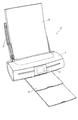
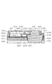
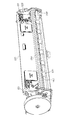
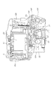
通常、ほとんどの市販インクジェットプリンタは、プリンタの全体的な構造および設計の一部を形成する印刷エンジンを有する。これに関して、プリンタユニットの本体は、通常、印字ヘッドおよび関連する媒体配送機構を収容するように構成され、これらの特徴は、プリンタユニットと一体である。 Typically, most commercial inkjet printers have a print engine that forms part of the overall structure and design of the printer. In this regard, the body of the printer unit is typically configured to accommodate a print head and associated media delivery mechanism, and these features are integral with the printer unit.
これは、媒体がプリンタユニットを通って小さい反復で進められる時に媒体上で前後に移動する印字ヘッドを使用するインクジェットプリンタに関して特にそうである。その場合に、往復する印字ヘッドは、通常、プリンタユニットの本体に取り付けられ、媒体入力ローラと媒体出力ローラの間でプリンタユニットの幅をトラバースできるようされ、媒体入力ローラおよび媒体出力ローラは、プリンタユニットの構造の一部を形成する。そのようなプリンタユニットを用いると、交換のために印字ヘッドを取り外すことを可能にすることができるが、媒体転送ローラ、制御回路網、およびメンテナンスステーションなどの印刷エンジンの他の部品は、通常、プリンタユニットに固定され、これらの部品の交換は、プリンタユニット全体を交換せずには不可能である。 This is especially true for inkjet printers that use print heads that move back and forth on the media as the media is advanced through the printer unit in small iterations. In that case, the reciprocating print head is usually attached to the main body of the printer unit so that the width of the printer unit can be traversed between the medium input roller and the medium output roller. Form part of the structure of the unit. Using such a printer unit can allow the print head to be removed for replacement, but other parts of the print engine such as media transfer rollers, control circuitry, and maintenance stations are usually It is fixed to the printer unit, and these parts cannot be replaced without replacing the entire printer unit.
どちらかといえばその設計構成において固定されているのと同様に、往復タイプの印字ヘッドを使用するプリンタユニットは、特にフルカラーおよび/または写真品質の印刷ジョブを実行する時に、かなり低速である。これは、印字ヘッドが、媒体の表面にインクを置くために静止媒体を継続的にトラバースしなければならず、イメージの1ラインを置くために印字ヘッドの複数の移動(swathe)を要する場合があるからである。 Rather than being fixed in its design configuration, printer units that use reciprocating printheads are considerably slower, especially when performing full color and / or photo quality print jobs. This is because the print head must continuously traverse the stationary media to place ink on the surface of the media and may require multiple swaths of the print head to place one line of the image. Because there is.
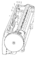
最近、印刷媒体の幅全体に延びる印字ヘッドを提供し、その結果、媒体が印字ヘッドを通って移動される時に印字ヘッドを静止したままにすることができるようにすることが可能になった。そのようなシステムは、印字ヘッドがイメージの1ラインを置くために複数の移動を実行する必要がもはやなく、印字ヘッドが、媒体が高速で通過する際に媒体にインクを置くことができるので、印刷を行える速度を大きく高める。そのような印字ヘッドは、以前に従来のインクジェットプリンタを用いて達成できなかった速度である60ページ毎分付近の速度でフルカラー1600dpi印刷を実行することを可能にする。 Recently, it has become possible to provide a print head that extends the entire width of the print media so that the print head can remain stationary as the media is moved through the print head. Such a system no longer needs to perform multiple movements for the printhead to place a line of the image, and the printhead can place ink on the media as it passes at high speeds. The speed at which printing can be performed is greatly increased. Such a printhead allows full color 1600 dpi printing to be performed at speeds around 60 pages per minute, a speed previously unattainable using conventional inkjet printers.
そのようなページ幅印字ヘッドは、通常、高い精度および高速の紙送りを必要とし、したがって、印刷エンジン全体(印字ヘッド、用紙ハンドリング機構、および制御回路網など)を、高品質出力を保証するためにそれ相応に構成しなければならない。したがって、プリンタユニットの標準的な本体の中でたやすく使用でき、印刷エンジンのすべての必要な部分が一貫した高速印刷を可能にする形で構成されることを保証する方3値で構成された、ページ幅印字ヘッドを有する印刷エンジンを提供する必要がある。 Such page width print heads typically require high accuracy and high speed paper feed, and therefore the entire print engine (print head, paper handling mechanism, and control circuitry, etc.) to ensure high quality output. Must be configured accordingly. Therefore, it is easy to use within the standard body of the printer unit, and is composed of three values that guarantee that all necessary parts of the print engine are configured in a way that allows consistent high speed printing There is a need to provide a print engine having a page width printhead.
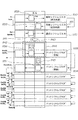
第1の態様で、本発明は、
印刷のために印刷媒体を供給する媒体入力トレイと、
前記印刷媒体にイメージを印刷する印刷エンジンと、
前記印刷された媒体を収集する媒体出力トレイと
を具備するインクジェットプリンタであって、
前記印刷エンジンが、ページ幅印字ヘッドおよびインク供給を有するタイプの取外し可能インクジェットカートリッジと、前記取外し可能インクジェットカートリッジを受け、印刷に関する前記印字ヘッドの動作を制御するように適合された本体を有するクレードルとを備える
インクジェットプリンタを提供する。
In a first aspect, the present invention provides:
A media input tray for supplying print media for printing;
A print engine for printing an image on the print medium;
An ink jet printer comprising a medium output tray for collecting the printed medium,
A removable ink jet cartridge of the type wherein the print engine has a page width print head and an ink supply; and a cradle having a body adapted to receive the removable ink jet cartridge and to control the operation of the print head for printing An inkjet printer is provided.
任意選択で、前記クレードルが、前記媒体入力トレイから印刷媒体を受け取り、印刷された媒体を前記媒体出力トレイに送るために、前記インクジェットプリンタに固定されるように構成される。 Optionally, the cradle is configured to be secured to the ink jet printer for receiving print media from the media input tray and sending printed media to the media output tray.
任意選択で、前記クレードルが、印刷のために前記媒体入力トレイから前記印字ヘッドへ、および前記印刷された媒体を収集するために前記印字ヘッドから前記媒体出力トレイへ、前記印刷媒体を転送する媒体転送機構を含む。 Optionally, the cradle transfers the print media from the media input tray to the print head for printing and from the print head to the media output tray for collecting the printed media. Includes transfer mechanism.
任意選択で、前記媒体搬送機構が、駆動ローラアセンブリおよび出口ローラアセンブリを備える。 Optionally, the media transport mechanism comprises a drive roller assembly and an exit roller assembly.
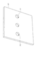
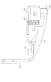
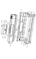
任意選択で、前記本体が、前記取外し可能インクジェットカートリッジを受ける凹窩を画定する。 Optionally, the body defines a recess that receives the removable ink jet cartridge.
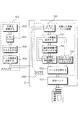
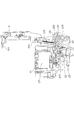
任意選択で、前記クレードルが、印刷を容易にするために前記印字ヘッドの動作を制御するコントローラを備える。 Optionally, the cradle comprises a controller that controls the operation of the print head to facilitate printing.
任意選択で、複数の端子が、前記コントローラと前記カートリッジとの間の電気通信を可能にするために、前記取外し可能インクジェットカートリッジの長さに沿って置かれた対応する端子と接触するように前記本体の長さに沿って置かれる。 Optionally, a plurality of terminals are in contact with corresponding terminals located along the length of the removable ink jet cartridge to allow electrical communication between the controller and the cartridge. Placed along the length of the body.
任意選択で、前記複数の端子が、前記凹窩内に置かれる。 Optionally, the plurality of terminals are placed in the recess.
任意選択で、前記コントローラが、プリント回路基板上に設けられる電気回路網の形であり、前記複数の端子が、前記プリント回路基板の表面に沿って形成される。 Optionally, the controller is in the form of an electrical network provided on a printed circuit board, and the plurality of terminals are formed along the surface of the printed circuit board.
任意選択で、前記コントローラが、前記印字ヘッドの動作を制御する1つまたは複数のSoPECデバイスを含む。 Optionally, the controller includes one or more SoPEC devices that control the operation of the printhead.
任意選択で、前記電気回路網が、前記プリント回路基板の1つの表面の上に設けられ、前記複数の端子が、前記プリント回路基板の反対の表面の上に設けられる。 Optionally, the electrical circuitry is provided on one surface of the printed circuit board and the plurality of terminals are provided on the opposite surface of the printed circuit board.
任意選択で、前記電気回路網が、前記取外し可能インクジェットカートリッジ上の前記対応する端子への伝送のために前記複数の端子にデータ信号および電力信号の形の電気信号を送る。 Optionally, the electrical network sends electrical signals in the form of data signals and power signals to the plurality of terminals for transmission to the corresponding terminals on the removable ink jet cartridge.
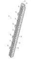
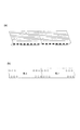
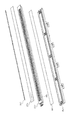
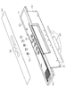
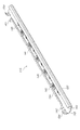
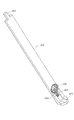
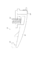
任意選択で、前記取外し可能インクジェットカートリッジの前記ページ幅印字ヘッドが、使用中に通る印刷媒体にインクを送るように配置された複数のノズルを有し、前記対応する端子が、電気コネクタ上に設けられ、前記電気コネクタが、前記印字ヘッドアセンブリの前記ノズルと電気的に通じ、前記印字ヘッドアセンブリの長さに沿って配置される。 Optionally, the page width print head of the removable ink jet cartridge has a plurality of nozzles arranged to deliver ink to a print medium that passes in use, and the corresponding terminals are provided on an electrical connector. And the electrical connector is in electrical communication with the nozzles of the printhead assembly and is disposed along the length of the printhead assembly.
任意選択で、前記複数のノズルが、実質的に前記印字ヘッドアセンブリの長さに延びる1つまたは複数の集積回路上に設けられる。 Optionally, the plurality of nozzles are provided on one or more integrated circuits that extend substantially the length of the printhead assembly.
任意選択で、各集積回路が、前記電気コネクタの一端がそれに取り付けられる1つまたは複数の接触パッドをその縁に沿って形成される。 Optionally, each integrated circuit is formed along its edge with one or more contact pads to which one end of the electrical connector is attached.
任意選択で、前記電気コネクタの自由端が、前記クレードルの前記コントローラから電力信号および/またはデータ信号を受け取る前記対応する端子を設けられる。 Optionally, the free end of the electrical connector is provided with the corresponding terminal for receiving power and / or data signals from the controller of the cradle.
任意選択で、前記電気コネクタが、前記印字ヘッドアセンブリの回りに延びるのに十分な長さおよび柔軟性を有する。 Optionally, the electrical connector has a length and flexibility sufficient to extend around the printhead assembly.
任意選択で、前記電気コネクタの前記自由端が、前記印字ヘッドアセンブリが前記カートリッジの表面に固定された時に前記カートリッジの前記表面に沿って受けられるように構成される。 Optionally, the free end of the electrical connector is configured to be received along the surface of the cartridge when the printhead assembly is secured to the surface of the cartridge.
任意選択で、前記電気コネクタの前記自由端が、その中に複数の穴を形成され、前記穴のそれぞれが、前記電気コネクタの前記自由端を前記カートリッジの前記表面で定位置に保持するために前記表面に形成されたスタッドを受けるように構成される。 Optionally, the free end of the electrical connector is formed with a plurality of holes therein, each of the holes for holding the free end of the electrical connector in place on the surface of the cartridge. It is configured to receive a stud formed on the surface.
任意選択で、前記電気コネクタの前記自由端が、前記カートリッジの前記表面で定位置に保持され、前記対応する端子が、前記電気コネクタの前記表面で露出される。 Optionally, the free end of the electrical connector is held in place on the surface of the cartridge and the corresponding terminal is exposed at the surface of the electrical connector.
任意選択で、前記電気コネクタが、フレキシブルプリント回路基板である。 Optionally, the electrical connector is a flexible printed circuit board.
任意選択で、前記クレードルが、媒体入力トレイから印刷媒体を受け取り、印刷された媒体を媒体出力トレイに送るために前記インクジェットプリンタに固定されるように構成される。 Optionally, the cradle is configured to receive print media from a media input tray and be secured to the inkjet printer for sending printed media to the media output tray.
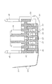
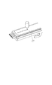
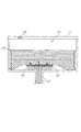
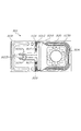
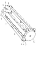
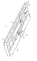
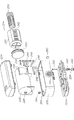
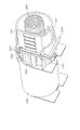
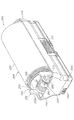
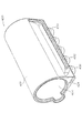
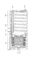
任意選択で、前記カートリッジが、
1つまたは複数のインク貯蔵コンパートメントを有する本体部分と、
前記本体に取り付け可能であり、前記1つまたは複数のコンパートメントからインクを受け取り、ページ幅印字ヘッドアセンブリの長さに沿って前記インクを分配するように構成された、前記ページ幅印字ヘッドアセンブリと
を備える。
Optionally, the cartridge is
A body portion having one or more ink storage compartments;
The page-width printhead assembly, attachable to the body, configured to receive ink from the one or more compartments and dispense the ink along the length of the page-width printhead assembly; Prepare.
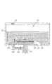
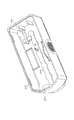
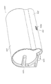
任意選択で、前記カートリッジが、
1つまたは複数のインク貯蔵コンパートメントを有する本体部分と、
前記本体部分に取り付け可能であり、印刷のために前記1つまたは複数のコンパートメントからインクを受け取るように構成された、ページ幅印字ヘッドアセンブリと、
前記印字ヘッドアセンブリの長さに沿って延びるように前記本体部分に取り付け可能なキャッパユニットであって、前記印字ヘッドアセンブリの表面と接触するために前記キャッパユニットに関して移動可能なキャッピング要素を収納する、前記キャッパユニットと
を備える。
Optionally, the cartridge is
A body portion having one or more ink storage compartments;
A page width printhead assembly attachable to the body portion and configured to receive ink from the one or more compartments for printing;
A capper unit attachable to the body portion so as to extend along the length of the printhead assembly, containing a capping element movable with respect to the capper unit to contact a surface of the printhead assembly And the capper unit.
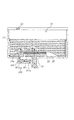
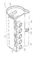
任意選択で、前記カートリッジが、
1つまたは複数のインク貯蔵コンパートメントを収納する本体部分と、
前記1つまたは複数のインク貯蔵コンパートメントからインクを受け取るように構成され、使用中に通る印刷媒体に前記インクを送るように配置された複数のノズルを有する、ページ幅印字ヘッドアセンブリと、
前記印字ヘッドアセンブリの前記ノズルと電気的に通じ、前記ノズルの動作を制御するために前記インクジェットプリンタの対応するコネクタと嵌合するために前記印字ヘッドアセンブリの長さに沿って配置された、電気コネクタと
を備える。
Optionally, the cartridge is
A body portion that houses one or more ink storage compartments;
A page-width printhead assembly having a plurality of nozzles configured to receive ink from the one or more ink storage compartments and arranged to deliver the ink to a print medium passing in use;
Electrically disposed along the length of the printhead assembly to be in electrical communication with the nozzles of the printhead assembly and to mate with corresponding connectors of the inkjet printer to control the operation of the nozzles And a connector.
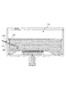
任意選択で、前記カートリッジが、
複数のインク貯蔵コンパートメントを有する本体部分と、
インク貯蔵コンパートメントからインクを受け取り、使用中に通る印刷媒体に前記インクを送るように配置された複数のノズルに前記インクを分配するように構成された、ページ幅印字ヘッドアセンブリと
を備え、
前記インク貯蔵コンパートメントが、前記印字ヘッドアセンブリの前記ノズルへの供給のために毛細管現象の下でその中に前記インクを貯蔵する吸収材料を備える。
Optionally, the cartridge is
A body portion having a plurality of ink storage compartments;
A page-width printhead assembly configured to receive ink from an ink storage compartment and to distribute the ink to a plurality of nozzles arranged to deliver the ink to a print medium that passes during use;
The ink storage compartment includes an absorbent material that stores the ink therein under capillary action for supply to the nozzles of the printhead assembly.
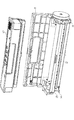
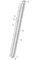
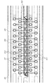
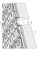
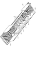
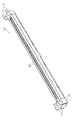
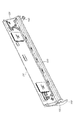
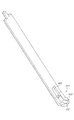
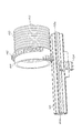
任意選択で、前記ページ幅印字ヘッドが、ページ幅印字ヘッドアセンブリに含まれ、前記ページ幅印字ヘッドアセンブリが、さらに、
1つまたは複数のインク供給源からインクを受け取り、前記インクを前記印字ヘッドアセンブリの長さに沿って分配する本体部分と、
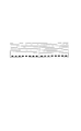
前記印字ヘッドアセンブリの長さに延びる複数の集積回路であって、各集積回路が、複数のノズルをその上に複数の行をなして形成され、前記ノズルのそれぞれが、使用中に通る印刷媒体に前記インクを送るように配置される、前記複数の集積回路と、
前記集積回路がその上に固定される、前記インクを前記本体部分から前記集積回路の前記ノズルに分配するインク分配部材と
を備え、
前記集積回路が、前記インク分配部材の長さにまたがって接触する配置で位置合せされる。
Optionally, the page width print head is included in a page width print head assembly, the page width print head assembly further comprising:
A body portion that receives ink from one or more ink sources and distributes the ink along the length of the printhead assembly;
A plurality of integrated circuits extending the length of the printhead assembly, each integrated circuit being formed with a plurality of nozzles in a plurality of rows thereon, each of the nozzles passing through in use A plurality of integrated circuits arranged to deliver the ink to
An ink distribution member, onto which the integrated circuit is secured, for distributing the ink from the body portion to the nozzles of the integrated circuit;
The integrated circuit is aligned in an arrangement that contacts the length of the ink distribution member.
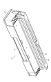
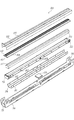
任意選択で、前記ページ幅印字ヘッドが、ページ幅印字ヘッドアセンブリに含まれ、前記ページ幅印字ヘッドアセンブリが、さらに、
1つまたは複数のインク供給源からインクを受け取り、前記インクを前記印字ヘッドアセンブリの長さに沿って分配する本体部分と、
実質的に前記印字ヘッドアセンブリの長さに延びる1つまたは複数の集積回路であって、前記1つまたは複数の集積回路のそれぞれが、その上に複数のノズルを形成され、前記ノズルのそれぞれが、使用中に通る印刷媒体に前記インクを送るように配置される、前記1つまたは複数の集積回路と、
前記1つまたは複数の集積回路のそれぞれがその上に固定される、前記インクを前記本体部分から前記1つまたは複数の集積回路のそれぞれの前記ノズルに分配するインク分配部材と
を備え、
前記本体部分が、前記印字ヘッドアセンブリと前記1つまたは複数のインク供給源との間のインクの流れを容易にするために、前記印字ヘッドアセンブリを前記1つまたは複数のインク供給源に固定する1つまたは複数のコネクタをその上に形成される。
Optionally, the page width print head is included in a page width print head assembly, the page width print head assembly further comprising:
A body portion that receives ink from one or more ink sources and distributes the ink along the length of the printhead assembly;
One or more integrated circuits extending substantially the length of the printhead assembly, each of the one or more integrated circuits having a plurality of nozzles formed thereon, each of the nozzles The one or more integrated circuits arranged to deliver the ink to a print medium that passes in use;
An ink distribution member that distributes the ink from the body portion to each of the nozzles of the one or more integrated circuits, each of which is fixed onto the one or more integrated circuits;
The body portion secures the print head assembly to the one or more ink sources to facilitate ink flow between the print head assembly and the one or more ink sources. One or more connectors are formed thereon.
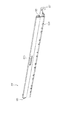
任意選択で、前記ページ幅印字ヘッドが、ページ幅印字ヘッドアセンブリに含まれ、前記ページ幅印字ヘッドアセンブリが、さらに、
1つまたは複数のインク供給源からインクを受け取り、前記インクを前記印字ヘッドアセンブリの長さに沿って分配する本体部分と、
実質的に前記印字ヘッドアセンブリの長さに延びる1つまたは複数の集積回路であって、前記1つまたは複数の集積回路のそれぞれが、その上に複数のノズルを形成され、前記ノズルのそれぞれが、使用中に通る印刷媒体に前記インクを送るように配置される、前記1つまたは複数の集積回路と、
前記1つまたは複数の集積回路のそれぞれがその上に固定される、前記インクを前記本体部分から前記1つまたは複数の集積回路のそれぞれの前記ノズルに分配するインク分配部材と
を備え、
前記1つまたは複数の集積回路のそれぞれと電気的に通じる電気コネクタが、前記インクジェットプリンタの対応する電気コネクタとの嵌合のために前記印字ヘッドアセンブリの長さに沿って延びる。
Optionally, the page width print head is included in a page width print head assembly, the page width print head assembly further comprising:
A body portion that receives ink from one or more ink sources and distributes the ink along the length of the printhead assembly;
One or more integrated circuits extending substantially the length of the printhead assembly, each of the one or more integrated circuits having a plurality of nozzles formed thereon, each of the nozzles The one or more integrated circuits arranged to deliver the ink to a print medium that passes in use;
An ink distribution member that distributes the ink from the body portion to each of the nozzles of the one or more integrated circuits, each of which is fixed onto the one or more integrated circuits;
An electrical connector in electrical communication with each of the one or more integrated circuits extends along the length of the printhead assembly for mating with a corresponding electrical connector of the inkjet printer.
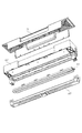
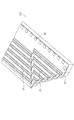
任意選択で、前記ページ幅印字ヘッドが、ページ幅印字ヘッドアセンブリに含まれ、前記ページ幅印字ヘッドアセンブリが、さらに、
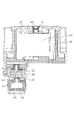
1つまたは複数のインク供給源からインクを受け取る本体部分であって、前記インクを実質的に前記印字ヘッドアセンブリの長さに沿って分配する1つまたは複数のチャネルをその中に形成された前記本体部分と、
実質的に前記印字ヘッドアセンブリの長さに延びる1つまたは複数の集積回路であって、前記1つまたは複数の集積回路のそれぞれが、複数のノズルを有し、前記ノズルのそれぞれが、使用中に通る印刷媒体に前記インクを送るように配置される、前記1つまたは複数の集積回路と、
前記1つまたは複数の集積回路のそれぞれがその上に固定される、前記インクを前記本体部分から前記集積回路のそれぞれに分配するインク分配部材と
を備え、
前記インク分配部材が、それを通って複数の導管を形成された単一要素であり、前記導管のそれぞれが、前記本体部分の前記チャネルのうちの1つからインクを受け取る入口と、前記1つまたは複数の集積回路の所定の個数のノズルに前記インクを送る出口とを有する。
Optionally, the page width print head is included in a page width print head assembly, the page width print head assembly further comprising:
A body portion for receiving ink from one or more ink sources, wherein the one or more channels are formed therein for distributing the ink substantially along the length of the printhead assembly. The body part,
One or more integrated circuits that extend substantially the length of the printhead assembly, each of the one or more integrated circuits having a plurality of nozzles, each of the nozzles being in use The one or more integrated circuits arranged to deliver the ink to a print medium passing through
An ink distribution member for distributing said ink from said body portion to each of said integrated circuits, each of said one or more integrated circuits being secured thereto;
The ink distribution member is a single element having a plurality of conduits formed therethrough, each of the conduits receiving an ink from one of the channels of the body portion; and the one Or an outlet for sending the ink to a predetermined number of nozzles of a plurality of integrated circuits.
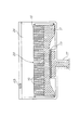
任意選択で、前記ページ幅印字ヘッドが、ページ幅印字ヘッドアセンブリに含まれ、前記ページ幅印字ヘッドアセンブリが、さらに、
1つまたは複数のインク供給源からインクを受け取る本体部分であって、前記インクを実質的に前記印字ヘッドアセンブリの長さに沿って分配する1つまたは複数のチャネルをその中に形成された前記本体部分と、
実質的に前記印字ヘッドアセンブリの長さに延びる1つまたは複数の集積回路であって、各集積回路が、複数のノズルを有し、前記ノズルのそれぞれが、使用中に通る印刷媒体に前記インクを送るように配置される、前記1つまたは複数の集積回路と、
その上に各集積回路が固定される、前記インクを前記本体部分から前記集積回路のそれぞれに分配するインク分配部材と
を備え、
前記インク分配部材が、各集積回路に送るために前記インクを前記本体部分の前記1つまたは複数のチャネルから向ける第1層と、前記インクを前記第1層から受け取るために、各集積回路を受け、定位置に固定する、前記第1層に取り付けられた第2層とを備える。
Optionally, the page width print head is included in a page width print head assembly, the page width print head assembly further comprising:
A body portion for receiving ink from one or more ink sources, wherein the one or more channels are formed therein for distributing the ink substantially along the length of the printhead assembly. The body part,
One or more integrated circuits extending substantially the length of the printhead assembly, each integrated circuit having a plurality of nozzles, each of the nozzles passing through the print medium during use Said one or more integrated circuits arranged to send
An ink distribution member that distributes the ink from the body portion to each of the integrated circuits, on which each integrated circuit is fixed, and
A first layer that directs the ink from the one or more channels of the body portion for delivery to the integrated circuit, and an integrated circuit for receiving the ink from the first layer. A second layer attached to the first layer for receiving and securing in place.
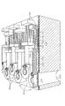
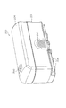
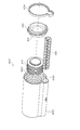
任意選択で、前記ユニットが、前記ページ幅印字ヘッドをキャップするキャッピングアセンブリを有し、前記キャッピングアセンブリが、
前記印字ヘッドの長さに延びるように構成された本体と、
前記本体の中に収納される、前記印字ヘッドの少なくとも一部をキャップするために前記本体に関して移動可能の、キャッピング要素と
を備え、
前記本体が、前記キャッピングアセンブリを前記印字ヘッドに取外し可能に取り付ける取付け要素を含む。
Optionally, the unit includes a capping assembly that caps the page width printhead, the capping assembly comprising:
A body configured to extend the length of the print head;
A capping element housed within the body and movable with respect to the body to cap at least a portion of the print head;
The body includes a mounting element that removably attaches the capping assembly to the printhead.
任意選択で、前記ユニットが、前記ページ幅印字ヘッドをキャップするキャッピングアセンブリを有し、前記キャッピングアセンブリが、
前記印字ヘッドの長さに延びるように構成された本体と、
前記本体の中に収納され、前記印字ヘッドの少なくとも一部をキャップするように適合されたリム部分を有する、キャッピング要素と
を備え、
前記キャッピング要素が、前記本体に関して第1位置と第2位置との間で移動可能であり、前記第1位置が、前記リム部分が前記本体から延びる位置であり、前記第2位置が、前記リム部分が前記本体の中に含まれる位置である。
Optionally, the unit includes a capping assembly that caps the page width printhead, the capping assembly comprising:
A body configured to extend the length of the print head;
A capping element housed in the body and having a rim portion adapted to cap at least a portion of the print head;
The capping element is moveable between a first position and a second position with respect to the body, the first position is a position where the rim portion extends from the body, and the second position is the rim. A portion is a position contained within the body.
任意選択で、前記ユニットが、前記ページ幅印字ヘッドをキャップするキャッピングアセンブリを有し、前記キャッピングアセンブリが、
前記印字ヘッドの長さに延びるように構成された本体と、
前記本体の中に収納され、前記本体に関して第1位置と第2位置との間で移動可能であるキャッピング要素であって、前記第1位置が、前記キャッピング要素の一部が前記本体から延びる位置であり、前記第2位置が、前記キャッピング要素が前記本体の中に含まれる位置である、前記キャッピング要素と
を備え、
前記キャッピング要素が、前記第1位置に偏らされる。
Optionally, the unit includes a capping assembly that caps the page width printhead, the capping assembly comprising:
A body configured to extend the length of the print head;
A capping element housed within the body and movable between a first position and a second position with respect to the body, wherein the first position is a position at which a portion of the capping element extends from the body. The capping element, wherein the second position is a position where the capping element is contained within the body;
The capping element is biased to the first position.
任意選択で、前記ユニットが、前記ページ幅印字ヘッドをキャップするキャッピングアセンブリを有し、前記キャッピングアセンブリが、
前記印字ヘッドの長さに延びるように構成された本体と、
前記本体の中に収納され、前記印字ヘッドの少なくとも一部をキャップするように適合されたリム部分を有する、キャッピング要素と、
前記キャッピング要素の前記リム部分が前記本体から延びる第1位置と前記キャッピング要素の前記リム部分が前記本体の中に含まれる第2位置との間で前記キャッピング要素を移動する、前記本体内に収納される、変位アセンブリと
を備え、
前記変位アセンブリが、前記位置を決定する電磁石によって制御される。
Optionally, the unit includes a capping assembly that caps the page width printhead, the capping assembly comprising:
A body configured to extend the length of the print head;
A capping element having a rim portion housed within the body and adapted to cap at least a portion of the print head;
Housed within the body, wherein the rim portion of the capping element moves the capping element between a first position where the rim portion extends from the body and a second position where the rim portion of the capping element is contained within the body. A displacement assembly; and
The displacement assembly is controlled by an electromagnet that determines the position.
任意選択で、前記クレードルの前記本体が、前記取外し可能インクジェットカートリッジに対して相補的であり、前記クレードルが、さらに、印刷を容易にするために前記印字ヘッドの動作を制御するコントローラを備え、
複数の端子が、前記コントローラと前記カートリッジとの間の電気通信を可能にするために、前記取外し可能インクジェットカートリッジの長さに沿って置かれた対応する端子と接触するために前記本体の長さに沿って置かれる。
Optionally, the body of the cradle is complementary to the removable ink jet cartridge, the cradle further comprising a controller that controls operation of the print head to facilitate printing;
The length of the body to contact a corresponding terminal located along the length of the removable ink jet cartridge to allow electrical communication between the controller and the cartridge. Placed along.
任意選択で、前記クレードルの前記本体が、前記取外し可能インクジェットカートリッジに対して相補的であり、前記クレードルが、さらに、
印刷を容易にするために前記印字ヘッドの動作を制御するコントローラと、
前記コントローラから前記カートリッジに設けられた対応する端子に制御信号を送るために前記コントローラと電気的に通じる複数の端子と
を備え、
前記複数の端子が、前記カートリッジが前記本体によって受けられる時に、前記カートリッジに設けられた前記対応する端子とピボット式に係合するように配置される。
Optionally, the body of the cradle is complementary to the removable ink jet cartridge, the cradle further comprising:
A controller for controlling the operation of the print head to facilitate printing;
A plurality of terminals in electrical communication with the controller to send control signals from the controller to corresponding terminals provided on the cartridge;
The plurality of terminals are arranged to pivotally engage the corresponding terminals provided on the cartridge when the cartridge is received by the body.
任意選択で、前記クレードルが、
ページ幅印字ヘッドおよび補充可能インク供給を有するタイプの取外し可能インクジェットカートリッジに対して相補的な本体と、
印刷を容易にするために前記印字ヘッドの動作を制御するコントローラと
を備えるクレードルユニットであり、
前記本体が、前記取外し可能インクジェットカートリッジを前記本体内に囲い込むカバーアセンブリを含み、前記カバーアセンブリが、その中に少なくとも1つのポートを形成され、前記少なくとも1つのポートを介して、補充ユニットが前記カートリッジの前記インク供給を補充するために受けられる。
Optionally, the cradle is
A body complementary to a removable ink jet cartridge of the type having a page width printhead and a refillable ink supply;
A cradle unit comprising a controller for controlling the operation of the print head to facilitate printing,
The body includes a cover assembly that encloses the removable ink jet cartridge within the body, the cover assembly having at least one port formed therein, through which the refill unit is Received to refill the ink supply of the cartridge.
任意選択で、前記クレードルが、
前記取外し可能インクジェットカートリッジに対して相補的であり、前記カートリッジに補充インクを供給する補充ユニットを受けるように構成された本体であって、前記補充ユニットから前記補充可能インク供給にインクを施与する補充アクチュエータを有する前記本体と、
印刷を容易にするために前記印字ヘッドの動作を制御するコントローラと
を備えるクレードルユニットである。
Optionally, the cradle is
A body complementary to the removable ink jet cartridge and configured to receive a replenishment unit that supplies replenishment ink to the cartridge, wherein the replenishment unit supplies ink from the replenishment unit Said body having a refill actuator;
A cradle unit including a controller for controlling the operation of the print head in order to facilitate printing.
任意選択で、前記クレードルが、前記取外し可能インクジェットカートリッジに対して相補的であり、電磁石アセンブリを取り付けられた本体を備えるクレードルユニットであり、前記電磁石アセンブリが、前記取外し可能インクジェットカートリッジの前記キャッパアセンブリを動作させるために前記コントローラによって制御され、
前記クレードルが、さらに、印刷を容易にするために前記印字ヘッドの動作を制御するコントローラを備える。
Optionally, the cradle is a cradle unit that is complementary to the removable inkjet cartridge and comprises a body with an electromagnet assembly attached thereto, the electromagnet assembly being the capper assembly of the removable inkjet cartridge. Controlled by the controller to operate
The cradle further includes a controller that controls the operation of the print head to facilitate printing.
任意選択で、前記ユニットが、さらに、前記クレードル用のカバーアセンブリを備え、前記クレードルが、前記取外し可能インクジェットカートリッジに対して相補的である本体と、印刷を容易にするために前記印字ヘッドの動作を制御するコントローラとを有し、
前記カバーアセンブリが、その中に形成された少なくとも1つのポートを備え、前記少なくとも1つのポートを介して、補充ユニットが、前記カートリッジの前記インク供給を補充するために受けられる。
Optionally, the unit further comprises a cover assembly for the cradle, the cradle being complementary to the removable inkjet cartridge, and operation of the print head to facilitate printing. And a controller for controlling
The cover assembly includes at least one port formed therein through which a refill unit is received for refilling the ink supply of the cartridge.
任意選択で、前記ユニットが、さらに、前記クレードル用のカバーアセンブリを備え、前記クレードルが、ページ幅印字ヘッドおよびインク供給を有するタイプの取外し可能インクジェットカートリッジに対して相補的である本体と、印刷を容易にするために前記印字ヘッドの動作を制御するコントローラとを備え、
前記カバーアセンブリが、インク補充ユニットから前記補充可能インク供給にインクを施与する補充アクチュエータを備える。
Optionally, the unit further comprises a cover assembly for the cradle, wherein the cradle is complementary to a removable ink jet cartridge of a type having a page width print head and an ink supply; and printing. A controller for controlling the operation of the print head in order to facilitate,
The cover assembly includes a refill actuator that applies ink from an ink refill unit to the refillable ink supply.
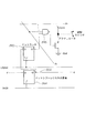
任意選択で、前記ユニットが、さらに、1つまたは複数のインク貯蔵コンパートメントと流体的に通じたページ幅印字ヘッドアセンブリを有するタイプのカートリッジユニット用のインクプライミングシステムを具備し、前記プライミングシステムが、
前記カートリッジをプライミングするインクの供給を受ける、前記印字ヘッドアセンブリに設けられたプライミング入口と、
前記印字ヘッドアセンブリと前記インク貯蔵コンパートメントのうちの1つとの間の流体接続をもたらすインク流れ通路と
を備え、
前記印字ヘッドアセンブリの前記プライミング入口に供給される前記インクが、前記印字ヘッドアセンブリと前記インク貯蔵コンパートメントとの両方にインクを同時にプライミングするために、前記印字ヘッドアセンブリから前記インク貯蔵コンパートメントへ前記インク流れ通路を介して流れる。
Optionally, the unit further comprises an ink priming system for a cartridge unit of the type having a page width printhead assembly in fluid communication with one or more ink storage compartments, the priming system comprising:
A priming inlet provided in the print head assembly for receiving a supply of ink for priming the cartridge;
An ink flow passage providing a fluid connection between the printhead assembly and one of the ink storage compartments;
The ink flow from the print head assembly to the ink storage compartment for the ink supplied to the priming inlet of the print head assembly to simultaneously prime ink to both the print head assembly and the ink storage compartment. Flow through the passage.
任意選択で、前記ユニットが、さらに、
前記カートリッジをプライミングするインクの供給を受ける、前記印字ヘッドアセンブリに設けられたプライミング入口と、
前記印字ヘッドアセンブリと前記インク貯蔵コンパートメントのうちの1つとの間の流体接続をもたらすインク流れ通路と、
前記インク流れ通路と前記インク貯蔵コンパートメントとの間の追加の流体接続をもたらすバイパス流れ通路と
を備えるインクプライミングシステムを具備し、
前記印字ヘッドアセンブリの前記プライミング入口に供給される前記インクが、前記印字ヘッドアセンブリと前記インク貯蔵コンパートメントとの両方にインクを同時にプライミングするために、前記印字ヘッドアセンブリから前記インク貯蔵コンパートメントへ前記インク流れ通路および前記バイパス流れ通路を介して流れる。
Optionally, the unit further comprises:
A priming inlet provided in the print head assembly for receiving a supply of ink for priming the cartridge;
An ink flow path that provides a fluid connection between the printhead assembly and one of the ink storage compartments;
An ink priming system comprising: a bypass flow passage providing an additional fluid connection between the ink flow passage and the ink storage compartment;
The ink flow from the print head assembly to the ink storage compartment for the ink supplied to the priming inlet of the print head assembly to simultaneously prime ink to both the print head assembly and the ink storage compartment. It flows through the passage and the bypass flow passage.
任意選択で、前記ユニットが、さらに、印刷液補充カートリッジおよび前記印刷液補充カートリッジ用の印刷液ディスペンサを具備し、前記液ディスペンサが、
印刷液を貯蔵し、前記印刷液がそれを介して施与される出口を有する、本体と、
前記本体から施与される前記印刷液の量を選択するように配置されたセレクタと
を備える。
Optionally, the unit further comprises a printing liquid replenishment cartridge and a printing liquid dispenser for the printing liquid replenishment cartridge, the liquid dispenser comprising:
A body having a outlet for storing the printing liquid and through which the printing liquid is applied;
A selector arranged to select an amount of the printing liquid applied from the main body.
さらなる態様で、前記印刷ユニットで印刷液の供給を補充する方法であって、
印刷液のディスペンサの出口を前記印刷ユニットの印刷液貯蔵室の入口と位置合せするために前記ディスペンサを前記印刷ユニットに取外し可能に取り付けるステップと、
前記印刷液貯蔵室を実質的に補充するのに必要な印刷液の量を判定するステップと、
前記ディスペンサから前記判定された量に対応する量の印刷液を選択的に施与するステップと
を含む方法が提供される。
In a further aspect, a method for replenishing a supply of printing fluid in the printing unit, comprising:
Removably attaching the dispenser to the printing unit to align the outlet of the printing liquid dispenser with the inlet of the printing liquid reservoir of the printing unit;
Determining the amount of printing fluid required to substantially replenish the printing fluid reservoir;
Selectively applying an amount of printing liquid corresponding to the determined amount from the dispenser.
さらなる態様で、前記インクジェットプリンタユニットが、印刷液補充カートリッジおよび前記補充カートリッジ用の施与アセンブリをさらに具備し、前記施与アセンブリが、
印刷液を貯蔵し、前記印刷液がそれを介して施与される出口を有する、本体と、
前記本体の貯蔵容量を選択的に変更し、プランジャの表面に沿って配置された一連の溝との移動可能保持部材の選択的係合によって前記出口を介して前記印刷液を放出し、これによって選択された量の印刷液を前記出口から施与するように配置された前記プランジャと
を備える。
In a further aspect, the inkjet printer unit further comprises a printing liquid refill cartridge and a dispensing assembly for the refill cartridge, the dispensing assembly comprising:
A body having a outlet for storing the printing liquid and through which the printing liquid is applied;
Selectively changing the storage capacity of the body and discharging the printing liquid through the outlet by selective engagement of a movable holding member with a series of grooves arranged along the surface of the plunger, thereby The plunger arranged to dispense a selected amount of printing fluid from the outlet.
さらなる態様で、前記インクジェットプリンタユニットが、印刷液補充ユニットによる印刷エンジンの補充を制御するシステムをさらに具備し、前記システムが、
前記補充ユニットに含まれる印刷液の量に関する情報を保管する、前記補充ユニットに組み込まれた情報記憶要素と、
前記補充ユニットが前記印刷エンジンに取り付けられた時に前記記憶要素によって保管された前記情報を読み取り、読み取られた前記情報に基づいて前記補充ユニットに含まれる前記印刷液による前記印刷エンジンの前記補充を制御する、前記印刷エンジンに組み込まれた情報リーダと
を含む。
In a further aspect, the inkjet printer unit further comprises a system for controlling replenishment of the print engine by the printing liquid replenishment unit, the system comprising:
An information storage element incorporated in the replenishment unit for storing information relating to the amount of printing liquid contained in the replenishment unit;
The information stored by the storage element is read when the replenishment unit is attached to the print engine, and the replenishment of the print engine by the printing liquid contained in the replenishment unit is controlled based on the read information. And an information reader incorporated in the print engine.
さらなる態様で、前記インクジェットプリンタユニットが、前記印刷エンジン用の印刷液補充ユニットを有し、前記補充ユニットが、前記補充ユニットに含まれる印刷液の量に関する情報を保管する情報記憶要素であって、前記補充ユニットが前記印刷エンジンに取り付けられた時に前記記憶要素によって保管された前記情報を読み取るために前記印刷エンジンに組み込まれた情報リーダと接続される、前記情報記憶要素を含み、
前記記憶要素によって保管される前記情報は、前記リーダが、前記補充ユニットに含まれる前記印刷液による前記印刷エンジンの前記補充を制御することを可能にする。
In a further aspect, the inkjet printer unit has a printing liquid replenishment unit for the print engine, and the replenishment unit is an information storage element that stores information regarding the amount of printing liquid contained in the replenishment unit, The information storage element connected to an information reader incorporated in the print engine to read the information stored by the storage element when the replenishment unit is attached to the print engine;
The information stored by the storage element allows the reader to control the replenishment of the print engine with the printing fluid contained in the replenishment unit.
さらなる態様で、印刷液補充カートリッジによる前記印刷ユニットの補充を制御する方法であって、
前記補充カートリッジに含まれる印刷液の量に関する情報を、それに組み込まれた情報記憶要素に保管するステップと、
前記補充カートリッジを前記印刷ユニットに取り付けるステップと、
前記印刷ユニットに組み込まれた情報リーダを用いて印刷液の前記量に関する前記情報を読み取るステップと、
読み取られた前記情報に基づいて前記補充カートリッジに含まれる印刷液による前記印刷ユニットの前記補充を制御するステップと
を含む方法が提供される。
In a further aspect, a method for controlling replenishment of the printing unit with a print liquid replenishment cartridge, comprising:
Storing information regarding the amount of printing liquid contained in the replenishment cartridge in an information storage element incorporated therein;
Attaching the replenishment cartridge to the printing unit;
Reading the information regarding the amount of printing liquid using an information reader incorporated in the printing unit;
Controlling the replenishment of the printing unit with the printing liquid contained in the replenishment cartridge based on the read information.
さらなる態様で、印刷液を貯蔵し、プリンタユニットの印字ヘッドの少なくとも1つの印刷液吐出ノズルに前記貯蔵された印刷液を供給するためにアレイに配置された複数の個々のチャネルを有する多孔性本体を備える印刷液貯蔵デバイスを有し、
前記チャネルのそれぞれの第1端が、毛細管現象の下でそこに貯蔵するために印刷液供給から印刷液を抽出するために前記印刷液供給と流体的に通じており、前記貯蔵された印刷液が、毛細管現象の下で前記少なくとも1つのノズルに供給される
インクジェットプリンタユニットが提供される。
In a further aspect, a porous body having a plurality of individual channels arranged in an array for storing printing liquid and supplying said stored printing liquid to at least one printing liquid discharge nozzle of a print head of a printer unit A printing liquid storage device comprising:
A first end of each of the channels is in fluid communication with the printing liquid supply for extracting printing liquid from a printing liquid supply for storage therein under capillary action; An inkjet printer unit is provided that is supplied to the at least one nozzle under capillary action.
第2の態様で、本発明は、
ページ幅印字ヘッドおよびインク供給を有するタイプの取外し可能インクジェットカートリッジと、
前記取外し可能インクジェットカートリッジを受け、印刷に関する前記印字ヘッドの動作を制御するように適合された本体を有するクレードルと
を備え
前記クレードルが、媒体入力トレイから印刷媒体を受け取り、印刷された媒体を媒体出力トレイに送るために、前記インクジェットプリンタに固定されるように構成される
インクジェットプリンタ用の印刷エンジンを提供する。
In a second aspect, the present invention provides:
A removable ink jet cartridge of the type having a page width printhead and an ink supply;
A cradle having a body adapted to receive the removable inkjet cartridge and to control the operation of the print head for printing, the cradle receiving print media from a media input tray and outputting the printed media to the media A print engine for an inkjet printer configured to be secured to the inkjet printer for delivery to a tray is provided.
任意選択で、前記クレードルが、印刷のために前記媒体入力トレイから前記印字ヘッドへ、および前記印刷された媒体を収集するために前記印字ヘッドから前記媒体出力トレイへ、前記印刷媒体を転送する媒体転送機構を含む。 Optionally, the cradle transfers the print media from the media input tray to the print head for printing and from the print head to the media output tray for collecting the printed media. Includes transfer mechanism.
任意選択で、前記媒体搬送機構が、駆動ローラアセンブリおよび出口ローラアセンブリを備える。 Optionally, the media transport mechanism comprises a drive roller assembly and an exit roller assembly.
任意選択で、前記本体が、前記取外し可能インクジェットカートリッジを受ける凹窩を画定する。 Optionally, the body defines a recess that receives the removable ink jet cartridge.
任意選択で、前記クレードルが、印刷を容易にするために前記印字ヘッドの動作を制御するコントローラを備える。 Optionally, the cradle comprises a controller that controls the operation of the print head to facilitate printing.
任意選択で、複数の端子が、前記コントローラと前記カートリッジとの間の電気通信を可能にするために、前記取外し可能インクジェットカートリッジの長さに沿って置かれた対応する端子と接触するように前記本体の長さに沿って置かれる。 Optionally, a plurality of terminals are in contact with corresponding terminals located along the length of the removable ink jet cartridge to allow electrical communication between the controller and the cartridge. Placed along the length of the body.
任意選択で、前記複数の端子が、前記凹窩内に置かれる。 Optionally, the plurality of terminals are placed in the recess.
任意選択で、前記コントローラが、プリント回路基板上に設けられる電気回路網の形であり、前記複数の端子が、前記プリント回路基板の表面に沿って形成される。 Optionally, the controller is in the form of an electrical network provided on a printed circuit board, and the plurality of terminals are formed along the surface of the printed circuit board.
任意選択で、前記コントローラが、前記印字ヘッドの動作を制御する1つまたは複数のSoPECデバイスを含む。 Optionally, the controller includes one or more SoPEC devices that control the operation of the printhead.
任意選択で、前記電気回路網が、前記プリント回路基板の1つの表面の上に設けられ、前記複数の端子が、前記プリント回路基板の反対の表面の上に設けられる。 Optionally, the electrical circuitry is provided on one surface of the printed circuit board and the plurality of terminals are provided on the opposite surface of the printed circuit board.
任意選択で、前記電気回路網が、前記取外し可能インクジェットカートリッジ上の前記対応する端子への伝送のために前記複数の端子にデータ信号および電力信号の形の電気信号を送る。 Optionally, the electrical network sends electrical signals in the form of data signals and power signals to the plurality of terminals for transmission to the corresponding terminals on the removable ink jet cartridge.
任意選択で、前記取外し可能インクジェットカートリッジの前記ページ幅印字ヘッドが、使用中に通る印刷媒体にインクを送るように配置された複数のノズルを有し、前記対応する端子が、電気コネクタ上に設けられ、前記電気コネクタが、前記印字ヘッドアセンブリの前記ノズルと電気的に通じ、前記印字ヘッドアセンブリの長さに沿って配置される。 Optionally, the page width print head of the removable ink jet cartridge has a plurality of nozzles arranged to deliver ink to a print medium that passes in use, and the corresponding terminals are provided on an electrical connector. And the electrical connector is in electrical communication with the nozzles of the printhead assembly and is disposed along the length of the printhead assembly.
任意選択で、前記複数のノズルが、実質的に前記印字ヘッドアセンブリの長さに延びる1つまたは複数の集積回路上に設けられる。 Optionally, the plurality of nozzles are provided on one or more integrated circuits that extend substantially the length of the printhead assembly.
任意選択で、各集積回路が、前記電気コネクタの一端がそれに取り付けられる1つまたは複数の接触パッドをその縁に沿って形成される。 Optionally, each integrated circuit is formed along its edge with one or more contact pads to which one end of the electrical connector is attached.
任意選択で、前記電気コネクタの自由端が、前記クレードルの前記コントローラから電力信号および/またはデータ信号を受け取る前記対応する端子を設けられる。 Optionally, the free end of the electrical connector is provided with the corresponding terminal for receiving power and / or data signals from the controller of the cradle.
任意選択で、前記電気コネクタが、前記印字ヘッドアセンブリの回りに延びるのに十分な長さおよび柔軟性を有する。 Optionally, the electrical connector has a length and flexibility sufficient to extend around the printhead assembly.
任意選択で、前記電気コネクタの前記自由端が、前記印字ヘッドアセンブリが前記カートリッジの表面に固定された時に前記カートリッジの前記表面に沿って受けられるように構成される。 Optionally, the free end of the electrical connector is configured to be received along the surface of the cartridge when the printhead assembly is secured to the surface of the cartridge.
任意選択で、前記電気コネクタの前記自由端が、その中に複数の穴を形成され、前記穴のそれぞれが、前記電気コネクタの前記自由端を前記カートリッジの前記表面で定位置に保持するために前記表面に形成されたスタッドを受けるように構成される。 Optionally, the free end of the electrical connector is formed with a plurality of holes therein, each of the holes for holding the free end of the electrical connector in place on the surface of the cartridge. It is configured to receive a stud formed on the surface.
任意選択で、前記電気コネクタの前記自由端が、前記カートリッジの前記表面で定位置に保持され、前記対応する端子が、前記電気コネクタの前記表面で露出される。 Optionally, the free end of the electrical connector is held in place on the surface of the cartridge and the corresponding terminal is exposed at the surface of the electrical connector.
任意選択で、前記電気コネクタが、フレキシブルプリント回路基板である。 Optionally, the electrical connector is a flexible printed circuit board.
任意選択で、前記エンジンが、前記印刷媒体にイメージを印刷するためにインクジェットプリンタユニット内で使用されるように配置され、前記プリンタユニットが、
印刷のために印刷媒体を供給する媒体入力トレイと、
前記印刷された媒体を収集する媒体出力トレイと
をも備え、
前記印刷エンジンが、ページ幅印字ヘッドおよびインク供給を有するタイプの取外し可能インクジェットカートリッジと、前記取外し可能インクジェットカートリッジを受け、印刷に関する前記印字ヘッドの動作を制御するように適合された本体を有するクレードルとを具備する。
Optionally, the engine is arranged to be used in an inkjet printer unit to print an image on the print medium, the printer unit comprising:
A media input tray for supplying print media for printing;
A media output tray for collecting the printed media,
A removable ink jet cartridge of the type wherein the print engine has a page width print head and an ink supply; and a cradle having a body adapted to receive the removable ink jet cartridge and to control the operation of the print head for printing It comprises.
任意選択で、前記カートリッジが、
1つまたは複数のインク貯蔵コンパートメントを有する本体部分と、
前記本体に取り付け可能であり、前記1つまたは複数のコンパートメントからインクを受け取り、ページ幅前記印字ヘッドアセンブリの長さに沿って前記インクを分配するように構成された、前記ページ幅印字ヘッドアセンブリと
を備える。
Optionally, the cartridge is
A body portion having one or more ink storage compartments;
The page width printhead assembly, attachable to the body, configured to receive ink from the one or more compartments and to distribute the ink along the length of the printhead assembly; Is provided.
任意選択で、前記カートリッジが、
1つまたは複数のインク貯蔵コンパートメントを有する本体部分と、
前記本体部分に取り付け可能であり、印刷のために前記1つまたは複数のコンパートメントからインクを受け取るように構成された、ページ幅印字ヘッドアセンブリと、
前記印字ヘッドアセンブリの長さに沿って延びるように前記本体部分に取り付け可能なキャッパユニットであって、前記印字ヘッドアセンブリの表面と接触するために前記キャッパユニットに関して移動可能なキャッピング要素を収納する、前記キャッパユニットと
を備える。
Optionally, the cartridge is
A body portion having one or more ink storage compartments;
A page width printhead assembly attachable to the body portion and configured to receive ink from the one or more compartments for printing;
A capper unit attachable to the body portion so as to extend along the length of the printhead assembly, containing a capping element movable with respect to the capper unit to contact a surface of the printhead assembly And the capper unit.
任意選択で、前記カートリッジが、
1つまたは複数のインク貯蔵コンパートメントを収納する本体部分と、
前記1つまたは複数のインク貯蔵コンパートメントからインクを受け取るように構成され、使用中に通る印刷媒体に前記インクを送るように配置された複数のノズルを有する、ページ幅印字ヘッドアセンブリと、
前記印字ヘッドアセンブリの前記ノズルと電気的に通じ、前記ノズルの動作を制御するために前記インクジェットプリンタの対応するコネクタと嵌合するために前記印字ヘッドアセンブリの長さに沿って配置された、電気コネクタと
を備える。
Optionally, the cartridge is
A body portion that houses one or more ink storage compartments;
A page-width printhead assembly having a plurality of nozzles configured to receive ink from the one or more ink storage compartments and arranged to deliver the ink to a print medium passing in use;
Electrically disposed along the length of the printhead assembly to be in electrical communication with the nozzles of the printhead assembly and to mate with corresponding connectors of the inkjet printer to control the operation of the nozzles And a connector.
さらなる態様で、前記カートリッジが、
複数のインク貯蔵コンパートメントを有する本体部分と、
インク貯蔵コンパートメントからインクを受け取り、使用中に通る印刷媒体に前記インクを送るように配置された複数のノズルに前記インクを分配するように構成された、ページ幅印字ヘッドアセンブリと
を備え、
前記インク貯蔵コンパートメントが、前記印字ヘッドアセンブリの前記ノズルへの供給のために毛細管現象の下でその中に前記インクを貯蔵する吸収材料を備える
印刷エンジンが提供される。
In a further aspect, the cartridge is
A body portion having a plurality of ink storage compartments;
A page-width printhead assembly configured to receive ink from an ink storage compartment and to distribute the ink to a plurality of nozzles arranged to deliver the ink to a print medium that passes during use;
A print engine is provided wherein the ink storage compartment comprises an absorbent material that stores the ink therein under capillary action for supply to the nozzles of the printhead assembly.
さらなる態様で、前記印刷エンジンが、
1つまたは複数のインク供給源からインクを受け取り、前記インクをページ幅印字ヘッドアセンブリの長さに沿って分配する本体部分と、
前記印字ヘッドアセンブリの長さに延びる複数の集積回路であって、各集積回路が、複数のノズルをその上に複数の行をなして形成され、前記ノズルのそれぞれが、使用中に通る印刷媒体に前記インクを送るように配置される、前記複数の集積回路と、
前記集積回路がその上に固定される、前記インクを前記本体部分から前記集積回路の前記ノズルに分配するインク分配部材と
を備える前記ページ幅印字ヘッドアセンブリを具備し、
前記集積回路が、前記インク分配部材の長さにまたがって接触する配置で位置合せされる
印刷エンジンが提供される。
In a further aspect, the print engine comprises:
A body portion that receives ink from one or more ink sources and distributes the ink along the length of the page-width printhead assembly;
A plurality of integrated circuits extending the length of the printhead assembly, each integrated circuit being formed with a plurality of nozzles in a plurality of rows thereon, each of the nozzles passing through in use A plurality of integrated circuits arranged to deliver the ink to
An ink distribution member that distributes the ink from the body portion to the nozzles of the integrated circuit, on which the integrated circuit is secured; and
A print engine is provided in which the integrated circuit is aligned in an arrangement that contacts the length of the ink distribution member.
さらなる態様で、前記印刷エンジンが、
1つまたは複数のインク供給源からインクを受け取り、前記インクをページ幅印字ヘッドアセンブリの長さに沿って分配する本体部分と、
実質的に前記印字ヘッドアセンブリの長さに延びる1つまたは複数の集積回路であって、前記1つまたは複数の集積回路のそれぞれが、その上に複数のノズルを形成され、前記ノズルのそれぞれが、使用中に通る印刷媒体に前記インクを送るように配置される、前記1つまたは複数の集積回路と、
前記1つまたは複数の集積回路のそれぞれがその上に固定される、前記インクを前記本体部分から前記1つまたは複数の集積回路のそれぞれの前記ノズルに分配するインク分配部材と
を有する前記ページ幅印字ヘッドアセンブリを具備し、
前記本体部分が、前記印字ヘッドアセンブリと前記1つまたは複数のインク供給源との間のインクの流れを容易にするために、前記印字ヘッドアセンブリを前記1つまたは複数のインク供給源に固定する1つまたは複数のコネクタをその上に形成される
印刷エンジンが提供される。
In a further aspect, the print engine comprises:
A body portion that receives ink from one or more ink sources and distributes the ink along the length of the page-width printhead assembly;
One or more integrated circuits extending substantially the length of the printhead assembly, each of the one or more integrated circuits having a plurality of nozzles formed thereon, each of the nozzles The one or more integrated circuits arranged to deliver the ink to a print medium that passes in use;
The page width having each of the one or more integrated circuits secured thereto for distributing the ink from the body portion to each of the nozzles of the one or more integrated circuits; A print head assembly;
The body portion secures the print head assembly to the one or more ink sources to facilitate ink flow between the print head assembly and the one or more ink sources. A print engine is provided having one or more connectors formed thereon.
さらなる態様で、前記印刷エンジンが、
1つまたは複数のインク供給源からインクを受け取り、前記インクをページ幅印字ヘッドアセンブリの長さに沿って分配する本体部分と、
実質的に前記印字ヘッドアセンブリの長さに延びる1つまたは複数の集積回路であって、前記1つまたは複数の集積回路のそれぞれが、その上に複数のノズルを形成され、前記ノズルのそれぞれが、使用中に通る印刷媒体に前記インクを送るように配置される、前記1つまたは複数の集積回路と、
前記1つまたは複数の集積回路のそれぞれがその上に固定される、前記インクを前記本体部分から前記1つまたは複数の集積回路のそれぞれの前記ノズルに分配するインク分配部材と
を含む前記ページ幅印字ヘッドアセンブリを具備し、
前記1つまたは複数の集積回路のそれぞれと電気的に通じる電気コネクタが、前記インクジェットプリンタの対応する電気コネクタとの嵌合のために前記印字ヘッドアセンブリの長さに沿って延びる
印刷エンジンが提供される。
In a further aspect, the print engine comprises:
A body portion that receives ink from one or more ink sources and distributes the ink along the length of the page-width printhead assembly;
One or more integrated circuits extending substantially the length of the printhead assembly, each of the one or more integrated circuits having a plurality of nozzles formed thereon, each of the nozzles The one or more integrated circuits arranged to deliver the ink to a print medium that passes in use;
The page width comprising: an ink distribution member that distributes the ink from the body portion to each of the nozzles of the one or more integrated circuits, each of which is fixed on the one or more integrated circuits; A print head assembly;
A print engine is provided in which an electrical connector in electrical communication with each of the one or more integrated circuits extends along the length of the printhead assembly for mating with a corresponding electrical connector of the inkjet printer. The
さらなる態様で、前記印刷エンジンが、
1つまたは複数のインク供給源からインクを受け取る本体部分であって、前記インクを実質的にページ幅印字ヘッドアセンブリの長さに沿って分配する1つまたは複数のチャネルをその中に形成された前記本体部分と、
実質的に前記印字ヘッドアセンブリの長さに延びる1つまたは複数の集積回路であって、前記1つまたは複数の集積回路のそれぞれが、複数のノズルを有し、前記ノズルのそれぞれが、使用中に通る印刷媒体に前記インクを送るように配置される、前記1つまたは複数の集積回路と、
前記1つまたは複数の集積回路のそれぞれがその上に固定される、前記インクを前記本体部分から前記集積回路のそれぞれに分配するインク分配部材と
を含む前記ページ幅印字ヘッドアセンブリを具備し、
前記インク分配部材が、それを通って複数の導管を形成された単一要素であり、前記導管のそれぞれが、前記本体部分の前記チャネルのうちの1つからインクを受け取る入口と、前記1つまたは複数の集積回路の所定の個数のノズルに前記インクを送る出口とを有する
印刷エンジンが提供される。
In a further aspect, the print engine comprises:
A body portion that receives ink from one or more ink sources and has formed therein one or more channels that distribute the ink substantially along the length of the page-width printhead assembly. The body portion;
One or more integrated circuits that extend substantially the length of the printhead assembly, each of the one or more integrated circuits having a plurality of nozzles, each of the nozzles being in use The one or more integrated circuits arranged to deliver the ink to a print medium passing through
An ink distribution member for distributing said ink from said body portion to each of said integrated circuits, each of said one or more integrated circuits being fixed thereon, and
The ink distribution member is a single element having a plurality of conduits formed therethrough, each of the conduits receiving an ink from one of the channels of the body portion; and the one Alternatively, a print engine having an outlet for sending the ink to a predetermined number of nozzles of a plurality of integrated circuits is provided.
さらなる態様で、前記印刷エンジンが、
1つまたは複数のインク供給源からインクを受け取る本体部分であって、前記インクを実質的にページ幅印字ヘッドアセンブリの長さに沿って分配する1つまたは複数のチャネルをその中に形成された前記本体部分と、
実質的に前記印字ヘッドアセンブリの長さに延びる1つまたは複数の集積回路であって、各集積回路が、複数のノズルを有し、前記ノズルのそれぞれが、使用中に通る印刷媒体に前記インクを送るように配置される、前記1つまたは複数の集積回路と、
その上に各集積回路が固定される、前記インクを前記本体部分から前記集積回路のそれぞれに分配するインク分配部材と
を含む前記ページ幅印字ヘッドアセンブリを具備し、
前記インク分配部材が、各集積回路に送るために前記インクを前記本体部分の前記1つまたは複数のチャネルから向ける第1層と、前記インクを前記第1層から受け取るために、各集積回路を受け、定位置に固定する、前記第1層に取り付けられた第2層とを備える
印刷エンジンが提供される。
In a further aspect, the print engine comprises:
A body portion that receives ink from one or more ink sources and has formed therein one or more channels that distribute the ink substantially along the length of the page-width printhead assembly. The body portion;
One or more integrated circuits extending substantially the length of the printhead assembly, each integrated circuit having a plurality of nozzles, each of the nozzles passing through the print medium during use Said one or more integrated circuits arranged to send
An ink distribution member for distributing the ink from the body portion to each of the integrated circuits, on which each integrated circuit is secured, and the page width printhead assembly,
A first layer for directing the ink from the one or more channels of the body portion for delivery to the integrated circuit, and an integrated circuit for receiving the ink from the first layer. A print engine is provided comprising a second layer attached to the first layer for receiving and securing in place.
さらなる態様で、前記印刷エンジンが、前記ページ幅印字ヘッドをキャップするキャッピングアセンブリを備え、前記キャッピングアセンブリが、
前記印字ヘッドの長さに延びるように構成された本体と、
前記本体の中に収納される、前記印字ヘッドの少なくとも一部をキャップするために前記本体に関して移動可能の、キャッピング要素と
を有し、
前記本体が、前記キャッピングアセンブリを前記印字ヘッドに取外し可能に取り付ける取付け要素を含む
印刷エンジンが提供される。
In a further aspect, the print engine comprises a capping assembly that caps the page-width printhead, the capping assembly comprising:
A body configured to extend the length of the print head;
A capping element housed within the body and movable with respect to the body to cap at least a portion of the print head;
A print engine is provided wherein the body includes a mounting element that removably attaches the capping assembly to the print head.
さらなる態様で、前記印刷エンジンが、前記ページ幅印字ヘッドをキャップするキャッピングアセンブリを備え、前記キャッピングアセンブリが、
前記印字ヘッドの長さに延びるように構成された本体と、
前記本体の中に収納され、前記印字ヘッドの少なくとも一部をキャップするように適合されたリム部分を有する、キャッピング要素と
を有し、
前記キャッピング要素が、前記本体に関して第1位置と第2位置との間で移動可能であり、前記第1位置が、前記リム部分が前記本体から延びる位置であり、前記第2位置が、前記リム部分が前記本体の中に含まれる位置である
印刷エンジンが提供される。
In a further aspect, the print engine comprises a capping assembly that caps the page-width printhead, the capping assembly comprising:
A body configured to extend the length of the print head;
A capping element housed within the body and having a rim portion adapted to cap at least a portion of the print head;
The capping element is moveable between a first position and a second position with respect to the body, the first position is a position where the rim portion extends from the body, and the second position is the rim. A print engine is provided in which the portion is a position contained within the body.
さらなる態様で、前記印刷エンジンが、前記ページ幅印字ヘッドをキャップするキャッピングアセンブリを備え、前記キャッピングアセンブリが、
前記印字ヘッドの長さに延びるように構成された本体と、
前記本体の中に収納され、前記本体に関して第1位置と第2位置との間で移動可能であるキャッピング要素であって、前記第1位置が、前記キャッピング要素の一部が前記本体から延びる位置であり、前記第2位置が、前記キャッピング要素が前記本体の中に含まれる位置である、前記キャッピング要素と
を有し、
前記キャッピング要素が、前記第1位置に偏らされる
印刷エンジンが提供される。
In a further aspect, the print engine comprises a capping assembly that caps the page-width printhead, the capping assembly comprising:
A body configured to extend the length of the print head;
A capping element housed within the body and movable between a first position and a second position with respect to the body, wherein the first position is a position at which a portion of the capping element extends from the body. The capping element, wherein the second position is a position where the capping element is contained within the body;
A print engine is provided in which the capping element is biased to the first position.
さらなる態様で、前記印刷エンジンが、前記ページ幅印字ヘッドをキャップするキャッピングアセンブリを備え、前記キャッピングアセンブリが、
前記印字ヘッドの長さに延びるように構成された本体と、
前記本体の中に収納され、前記印字ヘッドの少なくとも一部をキャップするように適合されたリム部分を有する、キャッピング要素と、
前記キャッピング要素の前記リム部分が前記本体から延びる第1位置と前記キャッピング要素の前記リム部分が前記本体の中に含まれる第2位置との間で前記キャッピング要素を移動する、前記本体内に収納される、変位アセンブリと
を有し、
前記変位アセンブリが、前記位置を決定する電磁石によって制御される
印刷エンジンが提供される。
In a further aspect, the print engine comprises a capping assembly that caps the page-width printhead, the capping assembly comprising:
A body configured to extend the length of the print head;
A capping element having a rim portion housed within the body and adapted to cap at least a portion of the print head;
Housed within the body, wherein the rim portion of the capping element moves the capping element between a first position where the rim portion extends from the body and a second position where the rim portion of the capping element is contained within the body. A displacement assembly; and
A print engine is provided in which the displacement assembly is controlled by an electromagnet that determines the position.
さらなる態様で、前記クレードルが、
前記取外し可能インクジェットカートリッジに対して相補的な本体と、
印刷を容易にするために前記印字ヘッドの動作を制御するコントローラと
を備えるクレードルユニットであり、
複数の端子が、前記コントローラと前記カートリッジとの間の電気通信を可能にするために、前記取外し可能インクジェットカートリッジの長さに沿って置かれた対応する端子と接触するために前記本体の長さに沿って置かれる
印刷エンジンが提供される。
In a further aspect, the cradle is
A body complementary to the removable ink jet cartridge;
A cradle unit comprising a controller for controlling the operation of the print head to facilitate printing,
The length of the body to contact a corresponding terminal located along the length of the removable ink jet cartridge to allow electrical communication between the controller and the cartridge. A print engine that is placed alongside is provided.
さらなる態様で、前記クレードルが、
前記取外し可能インクジェットカートリッジに対して相補的な本体と、
印刷を容易にするために前記印字ヘッドの動作を制御するコントローラと、
前記コントローラから前記カートリッジに設けられた対応する端子に制御信号を送るために前記コントローラと電気的に通じる複数の端子と
を備えるクレードルユニットであり、
前記複数の端子が、前記カートリッジが前記本体によって受けられる時に、前記カートリッジに設けられた前記対応する端子とピボット式に係合するように配置される
印刷エンジンが提供される。
In a further aspect, the cradle is
A body complementary to the removable ink jet cartridge;
A controller for controlling the operation of the print head to facilitate printing;
A cradle unit comprising a plurality of terminals in electrical communication with the controller to send control signals from the controller to corresponding terminals provided on the cartridge;
A print engine is provided in which the plurality of terminals are arranged to pivotally engage the corresponding terminals provided on the cartridge when the cartridge is received by the body.
さらなる態様で、前記クレードルが、
前記取外し可能インクジェットカートリッジに対して相補的な本体と、
印刷を容易にするために前記印字ヘッドの動作を制御するコントローラと
を備えるクレードルユニットであり、
前記本体が、前記取外し可能インクジェットカートリッジを前記本体内に囲い込むカバーアセンブリを含み、前記カバーアセンブリが、その中に少なくとも1つのポートを形成され、前記少なくとも1つのポートを介して、補充ユニットが前記カートリッジの前記インク供給を補充するために受けられる
印刷エンジンが提供される。
In a further aspect, the cradle is
A body complementary to the removable ink jet cartridge;
A cradle unit comprising a controller for controlling the operation of the print head to facilitate printing,
The body includes a cover assembly that encloses the removable ink jet cartridge within the body, the cover assembly having at least one port formed therein, through which the refill unit is A print engine is provided that is received to replenish the ink supply of the cartridge.
さらなる態様で、前記クレードルが、
前記取外し可能インクジェットカートリッジに対して相補的である本体と、
印刷を容易にするために前記印字ヘッドの動作を制御するコントローラと
を備えるクレードルユニットであり、
前記本体が、前記カートリッジに補充インクを供給する補充ユニットを受けるように構成され、前記本体が、前記補充ユニットから前記補充可能インク供給にインクを施与する補充アクチュエータを含む
印刷エンジンが提供される。
In a further aspect, the cradle is
A body that is complementary to the removable ink jet cartridge;
A cradle unit comprising a controller for controlling the operation of the print head to facilitate printing,
A print engine is provided wherein the body is configured to receive a refill unit that supplies refill ink to the cartridge, and wherein the body includes a refill actuator that applies ink from the refill unit to the refillable ink supply. .
さらなる態様で、前記クレードルが、
前記取外し可能インクジェットカートリッジに対して相補的である本体と、
印刷を容易にするために前記印字ヘッドの動作を制御するコントローラと
を備えるクレードルユニットであり、
前記本体が、それに取り付けられた電磁石アセンブリを含み、前記電磁石アセンブリが、前記取外し可能インクジェットカートリッジの前記キャッパアセンブリを動作させるために前記コントローラによって制御される
印刷エンジンが提供される。
In a further aspect, the cradle is
A body that is complementary to the removable ink jet cartridge;
A cradle unit comprising a controller for controlling the operation of the print head to facilitate printing,
A print engine is provided wherein the body includes an electromagnet assembly attached thereto, the electromagnet assembly being controlled by the controller to operate the capper assembly of the removable ink jet cartridge.
任意選択で、前記印刷エンジンが、ページ幅印字ヘッドおよびインク供給を有するタイプの取外し可能インクジェットカートリッジに対して相補的である本体と、印刷を容易にするために前記印字ヘッドの動作を制御するコントローラとを有する前記クレードルユニット用のカバーアセンブリを有し、前記カバーアセンブリが、その中に形成された少なくとも1つのポートを備え、前記少なくとも1つのポートを介して、補充ユニットが、前記カートリッジの前記インク供給を補充するために受けられる。 Optionally, the print engine is complementary to a removable ink jet cartridge of the type having a page width print head and an ink supply, and a controller that controls the operation of the print head to facilitate printing. A cover assembly for the cradle unit, the cover assembly comprising at least one port formed therein, through which the refill unit is connected to the ink of the cartridge. Received to replenish supplies.
任意選択で、前記印刷エンジンが、ページ幅印字ヘッドおよびインク供給を有するタイプの取外し可能インクジェットカートリッジに対して相補的である本体と、印刷を容易にするために前記印字ヘッドの動作を制御するコントローラとを有する前記クレードルユニット用のカバーアセンブリを有し、前記カバーアセンブリが、
インク補充ユニットから前記補充可能インク供給にインクを施与する補充アクチュエータ
を備える。
Optionally, the print engine is complementary to a removable ink jet cartridge of the type having a page width print head and an ink supply, and a controller that controls the operation of the print head to facilitate printing. A cover assembly for the cradle unit having the cover assembly comprising:
A replenishment actuator for applying ink from an ink replenishment unit to the replenishable ink supply;
任意選択で、前記印刷エンジンが、1つまたは複数のインク貯蔵コンパートメントと流体的に通じたページ幅印字ヘッドアセンブリを有するタイプの前記カートリッジユニット用のインクプライミングシステムを有し、前記システムが、
前記カートリッジユニットをプライミングするインクの供給を受ける、前記印字ヘッドアセンブリに設けられたプライミング入口と、
前記印字ヘッドアセンブリと前記インク貯蔵コンパートメントのうちの1つとの間の流体接続をもたらすインク流れ通路と
を備え、
前記印字ヘッドアセンブリの前記プライミング入口に供給される前記インクが、前記印字ヘッドアセンブリと前記インク貯蔵コンパートメントとの両方にインクを同時にプライミングするために、前記印字ヘッドアセンブリから前記インク貯蔵コンパートメントへ前記インク流れ通路を介して流れる。
Optionally, the print engine comprises an ink priming system for the cartridge unit of the type having a page width printhead assembly in fluid communication with one or more ink storage compartments, the system comprising:
A priming inlet provided in the print head assembly for receiving supply of ink for priming the cartridge unit;
An ink flow passage providing a fluid connection between the printhead assembly and one of the ink storage compartments;
The ink flow from the print head assembly to the ink storage compartment for the ink supplied to the priming inlet of the print head assembly to simultaneously prime ink to both the print head assembly and the ink storage compartment. Flow through the passage.
任意選択で、前記印刷エンジンが、1つまたは複数のインク貯蔵コンパートメントと流体的に通じたページ幅印字ヘッドアセンブリを有するタイプの前記カートリッジユニット用のインクプライミングシステムを有し、前記システムが、
前記カートリッジユニットをプライミングするインクの供給を受ける、前記印字ヘッドアセンブリに設けられたプライミング入口と、
前記印字ヘッドアセンブリと前記インク貯蔵コンパートメントのうちの1つとの間の流体接続をもたらすインク流れ通路と、
前記インク流れ通路と前記インク貯蔵コンパートメントとの間の追加の流体接続をもたらすバイパス流れ通路と
を備え、
前記印字ヘッドアセンブリの前記プライミング入口に供給される前記インクが、前記印字ヘッドアセンブリと前記インク貯蔵コンパートメントとの両方にインクを同時にプライミングするために、前記印字ヘッドアセンブリから前記インク貯蔵コンパートメントへ前記インク流れ通路および前記バイパス流れ通路を介して流れる。
Optionally, the print engine comprises an ink priming system for the cartridge unit of the type having a page width printhead assembly in fluid communication with one or more ink storage compartments, the system comprising:
A priming inlet provided in the print head assembly for receiving supply of ink for priming the cartridge unit;
An ink flow path that provides a fluid connection between the printhead assembly and one of the ink storage compartments;
A bypass flow passage providing an additional fluid connection between the ink flow passage and the ink storage compartment;
The ink flow from the print head assembly to the ink storage compartment for the ink supplied to the priming inlet of the print head assembly to simultaneously prime ink to both the print head assembly and the ink storage compartment. It flows through the passage and the bypass flow passage.
任意選択で、前記印刷エンジンが、
印刷液を貯蔵し、前記印刷液がそれを介して施与される出口を有する、本体と、
前記本体から施与される前記印刷液の量を選択するように配置されたセレクタと
を備える印刷液ディスペンサに関連する印刷液補充カートリッジと共に使用されるように配置される。
Optionally, the print engine is
A body having a outlet for storing the printing liquid and through which the printing liquid is applied;
Arranged to be used with a printing liquid replenishing cartridge associated with a printing liquid dispenser comprising a selector arranged to select an amount of the printing liquid dispensed from the body.
任意選択で、前記カートリッジが、
印刷液のディスペンサの出口を前記印刷ユニットの印刷液貯蔵室の入口と位置合せするために前記ディスペンサを前記印刷ユニットに取外し可能に取り付けるステップと、
前記印刷液貯蔵室を実質的に補充するのに必要な印刷液の量を判定するステップと、
前記ディスペンサから前記判定された量に対応する量の印刷液を選択的に施与するステップと
を含む方法によって印刷液の供給によって補充されるように配置される。
Optionally, the cartridge is
Removably attaching the dispenser to the printing unit to align the outlet of the printing liquid dispenser with the inlet of the printing liquid reservoir of the printing unit;
Determining the amount of printing fluid required to substantially replenish the printing fluid reservoir;
Selectively applying a quantity of printing liquid corresponding to the determined quantity from the dispenser.
任意選択で、前記印刷エンジンが、印刷液補充カートリッジ用の施与アセンブリと共に使用されるように配置され、前記施与アセンブリが、
印刷液を貯蔵し、前記印刷液がそれを介して施与される出口を有する、本体と、
前記本体の貯蔵容量を選択的に変更し、プランジャの表面に沿って配置された一連の溝との移動可能保持部材の選択的係合によって前記出口を介して前記印刷液を放出し、これによって選択された量の印刷液を前記出口から施与するように配置された前記プランジャと
を備える。
Optionally, the print engine is arranged to be used with a dispensing assembly for a print fluid refill cartridge, the dispensing assembly comprising:
A body having a outlet for storing the printing liquid and through which the printing liquid is applied;
Selectively changing the storage capacity of the body and discharging the printing liquid through the outlet by selective engagement of a movable holding member with a series of grooves arranged along the surface of the plunger, thereby The plunger arranged to dispense a selected amount of printing fluid from the outlet.
任意選択で、前記印刷エンジンが、印刷液補充ユニットによる前記印刷エンジンの補充を制御するシステムを有し、前記システムが、
前記補充ユニットに含まれる印刷液の量に関する情報を保管する、前記補充ユニットに組み込まれた情報記憶要素と、
前記補充ユニットが前記印刷エンジンに取り付けられた時に前記記憶要素によって保管された前記情報を読み取り、読み取られた前記情報に基づいて前記補充ユニットに含まれる前記印刷液による前記印刷エンジンの前記補充を制御する、前記印刷エンジンに組み込まれた情報リーダと
を含む。
Optionally, the print engine comprises a system for controlling replenishment of the print engine by a printing liquid replenishment unit, the system comprising:
An information storage element incorporated in the replenishment unit for storing information relating to the amount of printing liquid contained in the replenishment unit;
The information stored by the storage element is read when the replenishment unit is attached to the print engine, and the replenishment of the print engine by the printing liquid contained in the replenishment unit is controlled based on the read information. And an information reader incorporated in the print engine.
任意選択で、前記印刷エンジンが、印刷液補充ユニットに含まれる印刷液の量に関する情報を保管する情報記憶要素であって、前記補充ユニットが前記印刷エンジンに取り付けられた時に前記記憶要素によって保管された前記情報を読み取るために前記印刷エンジンに組み込まれた情報リーダと接続される、前記情報記憶要素を備える前記印刷液補充ユニットと共に使用されるように配置され、
前記記憶要素によって保管される前記情報は、前記リーダが、前記補充ユニットに含まれる前記印刷液による前記印刷エンジンの前記補充を制御することを可能にする。
Optionally, the print engine is an information storage element that stores information regarding the amount of printing liquid contained in the printing liquid replenishment unit, and is stored by the storage element when the replenishment unit is attached to the printing engine. Arranged for use with the printing liquid replenishment unit comprising the information storage element connected to an information reader incorporated in the print engine for reading the information;
The information stored by the storage element allows the reader to control the replenishment of the print engine with the printing fluid contained in the replenishment unit.
任意選択で、前記カートリッジが、印刷液補充カートリッジによる印刷液の供給によって補充されるように配置され、前記カートリッジの前記補充を制御する方法が、
前記補充カートリッジに含まれる印刷液の量に関する情報を、それに組み込まれた情報記憶要素に保管するステップと、
前記補充カートリッジを前記印刷ユニットに取り付けるステップと、
前記印刷ユニットに組み込まれた情報リーダを用いて印刷液の前記量に関する前記情報を読み取るステップと、
読み取られた前記情報に基づいて前記補充カートリッジに含まれる印刷液による前記印刷ユニットの前記補充を制御するステップと
を含む。
Optionally, the cartridge is arranged to be replenished by supply of printing fluid by a printing fluid replenishment cartridge, and the method of controlling the replenishment of the cartridge comprises
Storing information regarding the amount of printing liquid contained in the replenishment cartridge in an information storage element incorporated therein;
Attaching the replenishment cartridge to the printing unit;
Reading the information regarding the amount of printing liquid using an information reader incorporated in the printing unit;
Controlling the replenishment of the printing unit with the printing liquid contained in the replenishment cartridge based on the read information.
任意選択で、前記インクジェットカートリッジが、印刷液を貯蔵し、プリンタユニットの印字ヘッドの少なくとも1つの印刷液吐出ノズルに前記貯蔵された印刷液を供給するためにアレイに配置された複数の個々のチャネルを有する多孔性本体を備える印刷液貯蔵デバイスを具備し、
前記チャネルのそれぞれの第1端が、毛細管現象の下でそこに貯蔵するために印刷液供給から印刷液を抽出するために前記印刷液供給と流体的に通じており、前記貯蔵された印刷液が、毛細管現象の下で前記少なくとも1つのノズルに供給される。
Optionally, the inkjet cartridge stores a plurality of individual channels arranged in an array for storing printing fluid and supplying the stored printing fluid to at least one printing fluid discharge nozzle of a print head of a printer unit. Comprising a printing liquid storage device comprising a porous body having
Each first end of the channel is in fluid communication with the printing fluid supply for extracting printing fluid from the printing fluid supply for storage therein under capillary action, and the stored printing fluid Is supplied to the at least one nozzle under capillary action.
第3の態様で、本発明は、
1つまたは複数のインク貯蔵コンパートメントを有する本体部分と、
前記本体に取り付け可能であり、前記1つまたは複数のコンパートメントからインクを受け取り、ページ幅印字ヘッドアセンブリの長さに沿って前記インクを分配するように構成された、前記ページ幅印字ヘッドアセンブリと
を備える、インクジェットプリンタ用のカートリッジユニットを提供する。
In a third aspect, the present invention provides:
A body portion having one or more ink storage compartments;
The page-width printhead assembly, attachable to the body, configured to receive ink from the one or more compartments and dispense the ink along the length of the page-width printhead assembly; A cartridge unit for an inkjet printer is provided.
任意選択で、前記ページ幅印字ヘッドアセンブリが、その表面から突き出し、それに前記印字ヘッドアセンブリを固定するために前記本体部分によって受けられる複数のコネクタを含む。 Optionally, the page width printhead assembly includes a plurality of connectors that protrude from its surface and are received by the body portion to secure the printhead assembly thereto.
任意選択で、前記本体部分が、その表面に沿って1つまたは複数のインク出口を形成され、前記インク出口のそれぞれが、前記インク貯蔵コンパートメントのうちの1つに関連し、前記ページ幅印字ヘッドアセンブリがそれに取り付けられた時に前記ページ幅印字ヘッドアセンブリのインク入口を受けるように構成される。 Optionally, the body portion is formed with one or more ink outlets along its surface, each of the ink outlets being associated with one of the ink storage compartments, and the page width printhead The assembly is configured to receive an ink inlet of the page width printhead assembly when the assembly is attached thereto.
任意選択で、前記インク入口が、前記ページ幅印字ヘッドアセンブリから突き出す中空のチューブであり、前記印字ヘッドアセンブリにインクを送るのを容易にするために前記本体部分の前記インク出口内に受けられる。 Optionally, the ink inlet is a hollow tube that protrudes from the page width printhead assembly and is received within the ink outlet of the body portion to facilitate delivery of ink to the printhead assembly.
任意選択で、前記印字ヘッドアセンブリが、その長さに延びる1つまたは複数のインク供給チャネルを備え、前記インク供給チャネルのそれぞれが、前記インク入口のうちの1つだけからインクを受け取るように構成される。 Optionally, the printhead assembly comprises one or more ink supply channels extending along its length, each of the ink supply channels being configured to receive ink from only one of the ink inlets. Is done.
任意選択で、前記印字ヘッドアセンブリが、実質的にその長さに延びる1つまたは複数の集積回路を備え、前記1つまたは複数の集積回路のそれぞれが、その上に複数のノズルを形成され、前記ノズルのそれぞれが、使用中に、前記1つまたは複数のインク供給チャネルからインクを受け取り、通る印刷媒体に前記インクを送るように配置される。 Optionally, the printhead assembly comprises one or more integrated circuits extending substantially the length thereof, each of the one or more integrated circuits having a plurality of nozzles formed thereon, Each of the nozzles is arranged to receive ink from the one or more ink supply channels and to deliver the ink to a passing print medium during use.
任意選択で、インク分配部材が、前記インクを前記1つまたは複数のインク供給チャネルから前記集積回路の前記ノズルに分配する。 Optionally, an ink distribution member distributes the ink from the one or more ink supply channels to the nozzles of the integrated circuit.
任意選択で、前記集積回路が、前記インク分配部材の表面に固定される。 Optionally, the integrated circuit is secured to the surface of the ink distribution member.
任意選択で、前記集積回路が、前記インク分配部材の長さにまたがってエンドツーエンド配置で前記インク分配部材の前記表面に固定される。 Optionally, the integrated circuit is secured to the surface of the ink distribution member in an end-to-end arrangement across the length of the ink distribution member.
任意選択で、前記集積回路の端が、隣接する集積回路の間の長方形継手を容易にするために直線の縁を有する形状にされる。 Optionally, the ends of the integrated circuits are shaped with straight edges to facilitate rectangular joints between adjacent integrated circuits.
任意選択で、前記集積回路の端が、隣接する集積回路の間の傾斜した継手を容易にするために角度付きの縁を有する形状にされる。 Optionally, the end of the integrated circuit is shaped with angled edges to facilitate a sloped joint between adjacent integrated circuits.
任意選択で、隣接する集積回路が、前記インク分配部材の長さに沿って互いから垂直にオフセットされる。 Optionally, adjacent integrated circuits are vertically offset from each other along the length of the ink distribution member.
任意選択で、前記ノズルが、前記集積回路の表面に沿って傾斜した行で設けられる。 Optionally, the nozzles are provided in rows that are inclined along the surface of the integrated circuit.
任意選択で、前記角度付きの縁が、45°の角度を有する。 Optionally, said angled edge has an angle of 45 °.
任意選択で、前記角度付きの縁が、鋸歯プロファイルを有する。 Optionally, said angled edge has a sawtooth profile.
任意選択で、前記集積回路の1つの端に隣接する前記行のそれぞれの前記ノズルが、前記継手でのある度合のノズルオーバーラップを提供し、前記継手にまたがるノズルピッチを維持するために、前記ノズルの残りに関して垂直に変位される。 Optionally, each of the nozzles in the row adjacent to one end of the integrated circuit provides a degree of nozzle overlap at the joint to maintain a nozzle pitch across the joint. It is displaced vertically with respect to the rest of the nozzle.
任意選択で、前記垂直に変位されたノズルが、三角形構成で配置される。 Optionally, the vertically displaced nozzles are arranged in a triangular configuration.
任意選択で、前記垂直に変位されたノズルが、台形構成で配置される。 Optionally, the vertically displaced nozzles are arranged in a trapezoidal configuration.
任意選択で、隣接する集積回路の間の分離の距離が、15μ未満である。 Optionally, the separation distance between adjacent integrated circuits is less than 15μ.
さらなる態様で、前記インクジェットプリンタが、
印刷のために印刷媒体を供給する媒体入力トレイと、
前記印刷媒体にイメージを印刷する印刷エンジンと、
前記印刷された媒体を収集する媒体出力トレイと
を備えるインクジェットプリンタであり、
前記印刷エンジンが、前記カートリッジと、前記カートリッジを受け、印刷に関する前記印字ヘッドアセンブリの動作を制御するように適合された本体を有するクレードルとを備える
カートリッジが提供される。
In a further aspect, the inkjet printer comprises:
A media input tray for supplying print media for printing;
A print engine for printing an image on the print medium;
An ink jet printer comprising: a medium output tray for collecting the printed medium;
A cartridge is provided, wherein the print engine comprises the cartridge and a cradle having a body adapted to receive the cartridge and control the operation of the printhead assembly for printing.
さらなる態様で、インクジェットプリンタ用の印刷エンジン内で使用されるように配置され、前記印刷エンジンが、さらに、前記取外し可能インクジェットカートリッジを受け、印刷に関する前記印字ヘッドの動作を制御するように適合された本体を有するクレードルを備え、
前記クレードルが、媒体入力トレイから印刷媒体を受け取り、印刷された媒体を媒体出力トレイに送るために、前記インクジェットプリンタに固定されるように構成される
カートリッジが提供される。
In a further aspect, arranged for use in a print engine for an ink jet printer, the print engine is further adapted to receive the removable ink jet cartridge and to control the operation of the print head for printing. A cradle having a body,
A cartridge is provided wherein the cradle is configured to be secured to the ink jet printer for receiving print media from a media input tray and sending the printed media to the media output tray.
さらなる態様で、前記カートリッジが、前記印字ヘッドアセンブリの長さに沿って延びるように前記本体部分に取り付け可能なキャッパユニットをさらに備え、前記キャッパユニットが、前記印字ヘッドアセンブリの表面と接触するために前記キャッパユニットに関して移動可能なキャッピング要素を収納する、カートリッジが提供される。 In a further aspect, the cartridge further comprises a capper unit attachable to the body portion so as to extend along the length of the printhead assembly, the capper unit contacting a surface of the printhead assembly. For this purpose, a cartridge is provided which houses a capping element movable with respect to the capper unit.
さらなる態様で、前記ページ幅印字ヘッドアセンブリが、前記1つまたは複数のインク貯蔵コンパートメントからインクを受け取るように構成され、前記ページ幅印字ヘッドアセンブリが、使用中に通る印刷媒体に前記インクを送るように配置された複数のノズルを有し、前記カートリッジが、さらに、前記印字ヘッドアセンブリの前記ノズルと電気的に通じ、前記ノズルの動作を制御するために前記インクジェットプリンタの対応するコネクタと嵌合するために前記印字ヘッドアセンブリの長さに沿って配置された、電気コネクタを備える、カートリッジが提供される。 In a further aspect, the page width printhead assembly is configured to receive ink from the one or more ink storage compartments such that the page width printhead assembly delivers the ink to a print medium that passes in use. And the cartridge is further in electrical communication with the nozzles of the printhead assembly and mating with corresponding connectors of the ink jet printer to control the operation of the nozzles For this purpose, a cartridge is provided comprising an electrical connector disposed along the length of the printhead assembly.
さらなる態様で、前記ページ幅印字ヘッドアセンブリが、インク貯蔵コンパートメントからインクを受け取るように構成され、使用中に通る印刷媒体に前記インクを送るように配置された複数のノズルに前記インクを分配するように構成され、
前記インク貯蔵コンパートメントが、前記印字ヘッドアセンブリの前記ノズルへの供給のために毛細管現象の下でその中に前記インクを貯蔵する吸収材料を備える
カートリッジが提供される。
In a further aspect, the page-width printhead assembly is configured to receive ink from an ink storage compartment and distributes the ink to a plurality of nozzles arranged to deliver the ink to a print medium that is in use. Composed of
A cartridge is provided in which the ink storage compartment comprises an absorbent material for storing the ink therein under capillary action for supply to the nozzles of the printhead assembly.
さらなる態様で、前記ページ幅印字ヘッドアセンブリが、
1つまたは複数のインク供給源からインクを受け取り、前記インクを前記印字ヘッドアセンブリの長さに沿って分配する本体部分と、
前記印字ヘッドアセンブリの長さに延びる複数の集積回路であって、各集積回路が、複数のノズルをその上に複数の行をなして形成され、前記ノズルのそれぞれが、使用中に通る印刷媒体に前記インクを送るように配置される、前記複数の集積回路と、
前記集積回路がその上に固定される、前記インクを前記本体部分から前記集積回路の前記ノズルに分配するインク分配部材と
を備え、
前記集積回路が、前記インク分配部材の長さにまたがって接触する配置で位置合せされる
カートリッジが提供される。
In a further aspect, the page width printhead assembly comprises:
A body portion that receives ink from one or more ink sources and distributes the ink along the length of the printhead assembly;
A plurality of integrated circuits extending the length of the printhead assembly, each integrated circuit being formed with a plurality of nozzles in a plurality of rows thereon, each of the nozzles passing through in use A plurality of integrated circuits arranged to deliver the ink to
An ink distribution member, onto which the integrated circuit is secured, for distributing the ink from the body portion to the nozzles of the integrated circuit;
A cartridge is provided in which the integrated circuit is aligned in an arrangement that contacts the length of the ink distribution member.
さらなる態様で、前記ページ幅印字ヘッドアセンブリが、
1つまたは複数のインク供給源からインクを受け取り、前記インクを前記印字ヘッドアセンブリの長さに沿って分配する本体部分と、
実質的に前記印字ヘッドアセンブリの長さに延びる1つまたは複数の集積回路であって、前記1つまたは複数の集積回路のそれぞれが、その上に複数のノズルを形成され、前記ノズルのそれぞれが、使用中に通る印刷媒体に前記インクを送るように配置される、前記1つまたは複数の集積回路と、
前記1つまたは複数の集積回路のそれぞれがその上に固定される、前記インクを前記本体部分から前記1つまたは複数の集積回路のそれぞれの前記ノズルに分配するインク分配部材と
を備え、
前記本体部分が、前記印字ヘッドアセンブリと前記1つまたは複数のインク供給源との間のインクの流れを容易にするために、前記印字ヘッドアセンブリを前記1つまたは複数のインク供給源に固定する1つまたは複数のコネクタをその上に形成される
カートリッジが提供される。
In a further aspect, the page width printhead assembly comprises:
A body portion that receives ink from one or more ink sources and distributes the ink along the length of the printhead assembly;
One or more integrated circuits extending substantially the length of the printhead assembly, each of the one or more integrated circuits having a plurality of nozzles formed thereon, each of the nozzles The one or more integrated circuits arranged to deliver the ink to a print medium that passes in use;
An ink distribution member that distributes the ink from the body portion to each of the nozzles of the one or more integrated circuits, each of which is fixed onto the one or more integrated circuits;
The body portion secures the print head assembly to the one or more ink sources to facilitate ink flow between the print head assembly and the one or more ink sources. A cartridge is provided having one or more connectors formed thereon.
さらなる態様で、前記ページ幅印字ヘッドアセンブリが、
1つまたは複数のインク供給源からインクを受け取り、前記インクを前記印字ヘッドアセンブリの長さに沿って分配する本体部分と、
実質的に前記印字ヘッドアセンブリの長さに延びる1つまたは複数の集積回路であって、前記1つまたは複数の集積回路のそれぞれが、その上に複数のノズルを形成され、前記ノズルのそれぞれが、使用中に通る印刷媒体に前記インクを送るように配置される、前記1つまたは複数の集積回路と、
前記1つまたは複数の集積回路のそれぞれがその上に固定される、前記インクを前記本体部分から前記1つまたは複数の集積回路のそれぞれの前記ノズルに分配するインク分配部材と
を備え、
前記1つまたは複数の集積回路のそれぞれと電気的に通じる電気コネクタが、前記インクジェットプリンタの対応する電気コネクタとの嵌合のために前記印字ヘッドアセンブリの長さに沿って延びる
カートリッジが提供される。
In a further aspect, the page width printhead assembly comprises:
A body portion that receives ink from one or more ink sources and distributes the ink along the length of the printhead assembly;
One or more integrated circuits extending substantially the length of the printhead assembly, each of the one or more integrated circuits having a plurality of nozzles formed thereon, each of the nozzles The one or more integrated circuits arranged to deliver the ink to a print medium that passes in use;
An ink distribution member that distributes the ink from the body portion to each of the nozzles of the one or more integrated circuits, each of which is fixed onto the one or more integrated circuits;
An electrical connector in electrical communication with each of the one or more integrated circuits extends along the length of the printhead assembly for mating with a corresponding electrical connector of the inkjet printer. .
さらなる態様で、前記ページ幅印字ヘッドアセンブリが、
1つまたは複数のインク供給源からインクを受け取る本体部分であって、前記インクを実質的に前記印字ヘッドアセンブリの長さに沿って分配する1つまたは複数のチャネルをその中に形成された前記本体部分と、
実質的に前記印字ヘッドアセンブリの長さに延びる1つまたは複数の集積回路であって、前記1つまたは複数の集積回路のそれぞれが、複数のノズルを有し、前記ノズルのそれぞれが、使用中に通る印刷媒体に前記インクを送るように配置される、前記1つまたは複数の集積回路と、
前記1つまたは複数の集積回路のそれぞれがその上に固定される、前記インクを前記本体部分から前記集積回路のそれぞれに分配するインク分配部材と
を備え、
前記インク分配部材が、それを通って複数の導管を形成された単一要素であり、前記導管のそれぞれが、前記本体部分の前記チャネルのうちの1つからインクを受け取る入口と、前記1つまたは複数の集積回路の所定の個数のノズルに前記インクを送る出口とを有する
カートリッジが提供される。
In a further aspect, the page width printhead assembly comprises:
A body portion for receiving ink from one or more ink sources, wherein the one or more channels are formed therein for distributing the ink substantially along the length of the printhead assembly. The body part,
One or more integrated circuits that extend substantially the length of the printhead assembly, each of the one or more integrated circuits having a plurality of nozzles, each of the nozzles being in use The one or more integrated circuits arranged to deliver the ink to a print medium passing through
An ink distribution member for distributing said ink from said body portion to each of said integrated circuits, each of said one or more integrated circuits being secured thereto;
The ink distribution member is a single element having a plurality of conduits formed therethrough, each of the conduits receiving an ink from one of the channels of the body portion; and the one Alternatively, a cartridge having an outlet for sending the ink to a predetermined number of nozzles of a plurality of integrated circuits is provided.
さらなる態様で、前記ページ幅印字ヘッドアセンブリが、
1つまたは複数のインク供給源からインクを受け取る本体部分であって、前記インクを実質的に前記印字ヘッドアセンブリの長さに沿って分配する1つまたは複数のチャネルをその中に形成された前記本体部分と、
実質的に前記印字ヘッドアセンブリの長さに延びる1つまたは複数の集積回路であって、各集積回路が、複数のノズルを有し、前記ノズルのそれぞれが、使用中に通る印刷媒体に前記インクを送るように配置される、前記1つまたは複数の集積回路と、
その上に各集積回路が固定される、前記インクを前記本体部分から前記集積回路のそれぞれに分配するインク分配部材と
を備え、
前記インク分配部材が、各集積回路に送るために前記インクを前記本体部分の前記1つまたは複数のチャネルから向ける第1層と、前記インクを前記第1層から受け取るために、各集積回路を受け、定位置に固定する、前記第1層に取り付けられた第2層とを備える
カートリッジが提供される。
In a further aspect, the page width printhead assembly comprises:
A body portion for receiving ink from one or more ink sources, wherein the one or more channels are formed therein for distributing the ink substantially along the length of the printhead assembly. The body part,
One or more integrated circuits extending substantially the length of the printhead assembly, each integrated circuit having a plurality of nozzles, each of the nozzles passing through the print medium during use Said one or more integrated circuits arranged to send
An ink distribution member that distributes the ink from the body portion to each of the integrated circuits, on which each integrated circuit is fixed, and
A first layer that directs the ink from the one or more channels of the body portion for delivery to the integrated circuit, and an integrated circuit for receiving the ink from the first layer. A cartridge is provided comprising a second layer attached to the first layer for receiving and securing in place.
さらなる態様で、前記カートリッジが、前記ページ幅印字ヘッドをキャップするキャッピングアセンブリを有し、前記キャッピングアセンブリが、
前記印字ヘッドの長さに延びるように構成された本体と、
前記本体の中に収納される、前記印字ヘッドの少なくとも一部をキャップするために前記本体に関して移動可能の、キャッピング要素と
を備え、
前記本体が、前記キャッピングアセンブリを前記印字ヘッドに取外し可能に取り付ける取付け要素を含む
カートリッジが提供される。
In a further aspect, the cartridge has a capping assembly that caps the page width printhead, the capping assembly comprising:
A body configured to extend the length of the print head;
A capping element housed within the body and movable with respect to the body to cap at least a portion of the print head;
A cartridge is provided wherein the body includes a mounting element that removably attaches the capping assembly to the printhead.
さらなる態様で、前記カートリッジが、前記ページ幅印字ヘッドをキャップするキャッピングアセンブリを有し、前記キャッピングアセンブリが、
前記印字ヘッドの長さに延びるように構成された本体と、
前記本体の中に収納され、前記印字ヘッドの少なくとも一部をキャップするように適合されたリム部分を有する、キャッピング要素と
を備え、
前記キャッピング要素が、前記本体に関して第1位置と第2位置との間で移動可能であり、前記第1位置が、前記リム部分が前記本体から延びる位置であり、前記第2位置が、前記リム部分が前記本体の中に含まれる位置である
カートリッジが提供される。
In a further aspect, the cartridge has a capping assembly that caps the page width printhead, the capping assembly comprising:
A body configured to extend the length of the print head;
A capping element housed in the body and having a rim portion adapted to cap at least a portion of the print head;
The capping element is moveable between a first position and a second position with respect to the body, the first position is a position where the rim portion extends from the body, and the second position is the rim. A cartridge is provided in which the portion is a position contained within the body.
さらなる態様で、前記カートリッジが、前記ページ幅印字ヘッドをキャップするキャッピングアセンブリを有し、前記キャッピングアセンブリが、
前記印字ヘッドの長さに延びるように構成された本体と、
前記本体の中に収納され、前記本体に関して第1位置と第2位置との間で移動可能であるキャッピング要素であって、前記第1位置が、前記キャッピング要素の一部が前記本体から延びる位置であり、前記第2位置が、前記キャッピング要素が前記本体の中に含まれる位置である、前記キャッピング要素と
を備え、
前記キャッピング要素が、前記第1位置に偏らされる
カートリッジが提供される。
In a further aspect, the cartridge has a capping assembly that caps the page width printhead, the capping assembly comprising:
A body configured to extend the length of the print head;
A capping element housed within the body and movable between a first position and a second position with respect to the body, wherein the first position is a position at which a portion of the capping element extends from the body. The capping element, wherein the second position is a position where the capping element is contained within the body;
A cartridge is provided wherein the capping element is biased to the first position.
さらなる態様で、前記カートリッジが、前記ページ幅印字ヘッドをキャップするキャッピングアセンブリを有し、前記キャッピングアセンブリが、
前記印字ヘッドの長さに延びるように構成された本体と、
前記本体の中に収納され、前記印字ヘッドの少なくとも一部をキャップするように適合されたリム部分を有する、キャッピング要素と、
前記キャッピング要素の前記リム部分が前記本体から延びる第1位置と前記キャッピング要素の前記リム部分が前記本体の中に含まれる第2位置との間で前記キャッピング要素を移動する、前記本体内に収納される、変位アセンブリと
を備え、
前記変位アセンブリが、前記位置を決定する電磁石によって制御される
カートリッジが提供される。
In a further aspect, the cartridge has a capping assembly that caps the page width printhead, the capping assembly comprising:
A body configured to extend the length of the print head;
A capping element having a rim portion housed within the body and adapted to cap at least a portion of the print head;
Housed within the body, wherein the rim portion of the capping element moves the capping element between a first position where the rim portion extends from the body and a second position where the rim portion of the capping element is contained within the body. A displacement assembly; and
A cartridge is provided wherein the displacement assembly is controlled by an electromagnet that determines the position.
さらなる態様で、
前記カートリッジに対して相補的な本体と、
印刷を容易にするために前記印字ヘッドの動作を制御するコントローラと
を備えるクレードルユニットと共に使用されるように配置され、
複数の端子が、前記コントローラと前記カートリッジとの間の電気通信を可能にするために、前記取外し可能インクジェットカートリッジの長さに沿って置かれた対応する端子と接触するために前記本体の長さに沿って置かれる
カートリッジが提供される。
In a further aspect,
A body complementary to the cartridge;
Arranged to be used with a cradle unit comprising a controller for controlling the operation of the print head to facilitate printing,
The length of the body to contact a corresponding terminal located along the length of the removable ink jet cartridge to allow electrical communication between the controller and the cartridge. A cartridge is provided that is placed along with.
さらなる態様で、
前記カートリッジに対して相補的な本体と、
印刷を容易にするために前記印字ヘッドの動作を制御するコントローラと、
前記コントローラから前記カートリッジに設けられた対応する端子に制御信号を送るために前記コントローラと電気的に通じる複数の端子と
を備えるクレードルユニットと共に使用されるように配置され、
前記複数の端子が、前記カートリッジが前記本体によって受けられる時に、前記カートリッジに設けられた前記対応する端子とピボット式に係合するように配置される
カートリッジが提供される。
In a further aspect,
A body complementary to the cartridge;
A controller for controlling the operation of the print head to facilitate printing;
Arranged to be used with a cradle unit comprising a plurality of terminals in electrical communication with the controller to send control signals from the controller to corresponding terminals provided on the cartridge;
A cartridge is provided in which the plurality of terminals are arranged to pivotally engage the corresponding terminals provided on the cartridge when the cartridge is received by the body.
さらなる態様で、
前記カートリッジに対して相補的な本体と、
印刷を容易にするために前記印字ヘッドの動作を制御するコントローラと
を備えるクレードルユニットと共に使用されるように配置され、
前記本体が、前記取外し可能インクジェットカートリッジを前記本体内に囲い込むカバーアセンブリを含み、前記カバーアセンブリが、その中に少なくとも1つのポートを形成され、前記少なくとも1つのポートを介して、補充ユニットが前記カートリッジの前記インク供給を補充するために受けられる
カートリッジが提供される。
In a further aspect,
A body complementary to the cartridge;
Arranged to be used with a cradle unit comprising a controller for controlling the operation of the print head to facilitate printing,
The body includes a cover assembly that encloses the removable ink jet cartridge within the body, the cover assembly having at least one port formed therein, through which the refill unit is A cartridge is provided that is received to replenish the ink supply of the cartridge.
さらなる態様で、
前記カートリッジに対して相補的である本体と、
印刷を容易にするために前記印字ヘッドの動作を制御するコントローラと
を備えるクレードルユニットと共に使用されるように配置され、
前記本体が、前記カートリッジに補充インクを供給する補充ユニットを受けるように構成され、前記本体が、前記補充ユニットから前記補充可能インク供給にインクを施与する補充アクチュエータを含む
カートリッジが提供される。
In a further aspect,
A body that is complementary to the cartridge;
Arranged to be used with a cradle unit comprising a controller for controlling the operation of the print head to facilitate printing,
A cartridge is provided wherein the body is configured to receive a refill unit that supplies refill ink to the cartridge, and the body includes a refill actuator that applies ink from the refill unit to the refillable ink supply.
さらなる態様で、
前記カートリッジに対して相補的である本体と、
印刷を容易にするために前記印字ヘッドの動作を制御するコントローラと
を備えるクレードルユニットと共に使用されるように配置され、
前記本体が、それに取り付けられた電磁石アセンブリを含み、前記電磁石アセンブリが、前記取外し可能インクジェットカートリッジの前記キャッパアセンブリを動作させるために前記コントローラによって制御される
カートリッジが提供される。
In a further aspect,
A body that is complementary to the cartridge;
Arranged to be used with a cradle unit comprising a controller for controlling the operation of the print head to facilitate printing,
A cartridge is provided wherein the body includes an electromagnet assembly attached thereto, the electromagnet assembly being controlled by the controller to operate the capper assembly of the removable ink jet cartridge.
さらなる態様で、前記カートリッジに対して相補的である本体と、印刷を容易にするために前記印字ヘッドの動作を制御するコントローラとを有する、カバーアセンブリと共に使用されるように配置されたクレードルユニットと共に使用されるように適合され、
前記カバーアセンブリが、その中に形成された少なくとも1つのポートを備え、前記少なくとも1つのポートを介して、補充ユニットが、前記カートリッジの前記インク供給を補充するために受けられる
カートリッジが提供される。
In a further aspect, with a cradle unit arranged for use with a cover assembly having a body that is complementary to the cartridge and a controller that controls operation of the print head to facilitate printing. Adapted to be used,
A cartridge is provided wherein the cover assembly comprises at least one port formed therein, through which a refill unit is received to refill the ink supply of the cartridge.
さらなる態様で、前記カートリッジに対して相補的である本体と、インク供給と、印刷を容易にするために前記印字ヘッドの動作を制御するコントローラとを有する、カバーアセンブリと共に使用されるように配置されたインクジェットプリンタのクレードルユニットと共に使用されるように適合され、
前記カバーアセンブリが、インク補充ユニットから前記補充可能インク供給にインクを施与する補充アクチュエータを備える
カートリッジが提供される。
In a further aspect, arranged for use with a cover assembly having a body that is complementary to the cartridge, an ink supply, and a controller that controls the operation of the print head to facilitate printing. Adapted for use with cradle units of inkjet printers,
A cartridge is provided wherein the cover assembly includes a refill actuator for applying ink from an ink refill unit to the refillable ink supply.
さらなる態様で、前記カートリッジをプライミングするインクプライミングシステムと共に使用されるように配置され、前記システムが、
前記カートリッジをプライミングするインクの供給を受ける、前記印字ヘッドアセンブリに設けられたプライミング入口と、
前記印字ヘッドアセンブリと前記インク貯蔵コンパートメントのうちの1つとの間の流体接続をもたらすインク流れ通路と
を備え、
前記印字ヘッドアセンブリの前記プライミング入口に供給される前記インクが、前記印字ヘッドアセンブリと前記インク貯蔵コンパートメントとの両方にインクを同時にプライミングするために、前記印字ヘッドアセンブリから前記インク貯蔵コンパートメントへ前記インク流れ通路を介して流れる
カートリッジが提供される。
In a further aspect, arranged for use with an ink priming system for priming the cartridge, the system comprising:
A priming inlet provided in the print head assembly for receiving a supply of ink for priming the cartridge;
An ink flow passage providing a fluid connection between the printhead assembly and one of the ink storage compartments;
The ink flow from the print head assembly to the ink storage compartment for the ink supplied to the priming inlet of the print head assembly to simultaneously prime ink to both the print head assembly and the ink storage compartment. A cartridge is provided that flows through the passage.
さらなる態様で、前記カートリッジをプライミングするインクプライミングシステムと共に使用されるように適合され、前記システムが、
前記カートリッジをプライミングするインクの供給を受ける、前記印字ヘッドアセンブリに設けられたプライミング入口と、
前記印字ヘッドアセンブリと前記インク貯蔵コンパートメントのうちの1つとの間の流体接続をもたらすインク流れ通路と、
前記インク流れ通路と前記インク貯蔵コンパートメントとの間の追加の流体接続をもたらすバイパス流れ通路と
を備え、
前記印字ヘッドアセンブリの前記プライミング入口に供給される前記インクが、前記印字ヘッドアセンブリと前記インク貯蔵コンパートメントとの両方にインクを同時にプライミングするために、前記印字ヘッドアセンブリから前記インク貯蔵コンパートメントへ前記インク流れ通路および前記バイパス流れ通路を介して流れる
カートリッジが提供される。
In a further aspect, adapted for use with an ink priming system for priming the cartridge, the system comprising:
A priming inlet provided in the print head assembly for receiving a supply of ink for priming the cartridge;
An ink flow path that provides a fluid connection between the printhead assembly and one of the ink storage compartments;
A bypass flow passage providing an additional fluid connection between the ink flow passage and the ink storage compartment;
The ink flow from the print head assembly to the ink storage compartment for the ink supplied to the priming inlet of the print head assembly to simultaneously prime ink to both the print head assembly and the ink storage compartment. A cartridge is provided that flows through the passage and the bypass flow passage.
さらなる態様で、
印刷液を貯蔵し、前記印刷液がそれを介して施与される出口を有する、本体と、
前記本体から施与される前記印刷液の量を選択するように配置されたセレクタと
を備える印刷液ディスペンサを有する印刷液補充カートリッジと共に使用されるように適合された、カートリッジが提供される。
In a further aspect,
A body having a outlet for storing the printing liquid and through which the printing liquid is applied;
A cartridge is provided that is adapted for use with a printing fluid refill cartridge having a printing fluid dispenser comprising a selector arranged to select an amount of the printing fluid dispensed from the body.
さらなる態様で、
印刷液のディスペンサの出口を前記印刷ユニットの印刷液貯蔵室の入口と位置合せするために前記ディスペンサを前記印刷ユニットに取外し可能に取り付けるステップと、
前記印刷液貯蔵室を実質的に補充するのに必要な印刷液の量を判定するステップと、
前記ディスペンサから前記判定された量に対応する量の印刷液を選択的に施与するステップと
を含む方法によって印刷液補充カートリッジからの印刷液の供給によって補充されるように適合された、カートリッジが提供される。
In a further aspect,
Removably attaching the dispenser to the printing unit to align the outlet of the printing liquid dispenser with the inlet of the printing liquid reservoir of the printing unit;
Determining the amount of printing fluid required to substantially replenish the printing fluid reservoir;
Selectively applying a quantity of printing liquid corresponding to the determined quantity from the dispenser, wherein the cartridge is adapted to be replenished by supply of printing liquid from a printing liquid replenishing cartridge. Provided.
さらなる態様で、
印刷液を貯蔵し、前記印刷液がそれを介して施与される出口を有する、本体と、
前記本体の貯蔵容量を選択的に変更し、プランジャの表面に沿って配置された一連の溝との移動可能保持部材の選択的係合によって前記出口を介して前記印刷液を放出し、これによって選択された量の印刷液を前記出口から施与するように配置された前記プランジャと
を備える施与アセンブリを有する印刷液補充カートリッジと共に使用されるように配置された、カートリッジが提供される。
In a further aspect,
A body having a outlet for storing the printing liquid and through which the printing liquid is applied;
Selectively changing the storage capacity of the body and discharging the printing liquid through the outlet by selective engagement of a movable holding member with a series of grooves arranged along the surface of the plunger, thereby A cartridge is provided that is arranged for use with a printing fluid replenishment cartridge having a dispensing assembly that includes a plunger that is arranged to dispense a selected amount of printing fluid from the outlet.
さらなる態様で、印刷液補充カートリッジと共に使用されるように配置され、印刷液補充ユニットによる前記カートリッジの補充を制御するシステムが、
前記補充ユニットに含まれる印刷液の量に関する情報を保管する、前記補充ユニットに組み込まれた情報記憶要素と、
前記補充ユニットが前記印刷エンジンに取り付けられた時に前記記憶要素によって保管された前記情報を読み取り、読み取られた前記情報に基づいて前記補充ユニットに含まれる前記印刷液による前記印刷エンジンの前記補充を制御する、前記印刷エンジンに組み込まれた情報リーダと
を備える
カートリッジが提供される。
In a further aspect, a system that is arranged for use with a printing fluid replenishment cartridge and that controls replenishment of the cartridge by a printing fluid replenishment unit,
An information storage element incorporated in the replenishment unit for storing information relating to the amount of printing liquid contained in the replenishment unit;
The information stored by the storage element is read when the replenishment unit is attached to the print engine, and the replenishment of the print engine by the printing liquid contained in the replenishment unit is controlled based on the read information. An information reader incorporated in the print engine is provided.
さらなる態様で、印刷エンジン用の印刷液補充ユニットと共に使用されるように配置され、前記補充ユニットが、前記補充ユニットに含まれる印刷液の量に関する情報を保管する情報記憶要素であって、前記補充ユニットが前記印刷エンジンに取り付けられた時に前記記憶要素によって保管された前記情報を読み取るために前記印刷エンジンに組み込まれた情報リーダと接続される、前記情報記憶要素を備え、
前記記憶要素によって保管される前記情報は、前記リーダが、前記補充ユニットに含まれる前記印刷液による前記印刷エンジンの前記補充を制御することを可能にする
カートリッジが提供される。
In a further aspect, arranged for use with a printing fluid replenishment unit for a print engine, the replenishment unit being an information storage element for storing information regarding the amount of printing fluid contained in the replenishing unit, wherein the replenishment The information storage element connected to an information reader incorporated in the print engine to read the information stored by the storage element when a unit is attached to the print engine;
The information stored by the storage element is provided with a cartridge that allows the reader to control the replenishment of the print engine with the printing fluid contained in the replenishment unit.
さらなる態様で、前記カートリッジが、印刷液補充カートリッジと共に使用されるように配置され、前記補充カートリッジによる前記インクジェットカートリッジの補充を制御する方法が、
前記補充カートリッジに含まれる印刷液の量に関する情報を、それに組み込まれた情報記憶要素に保管するステップと、
前記補充カートリッジを前記印刷ユニットに取り付けるステップと、
前記印刷ユニットに組み込まれた情報リーダを用いて印刷液の前記量に関する前記情報を読み取るステップと、
読み取られた前記情報に基づいて前記補充カートリッジに含まれる印刷液による前記印刷ユニットの前記補充を制御するステップと
を含む
カートリッジが提供される。
In a further aspect, a method for controlling refilling of the inkjet cartridge with the refill cartridge, wherein the cartridge is arranged for use with a printing fluid refill cartridge, and
Storing information regarding the amount of printing liquid contained in the replenishment cartridge in an information storage element incorporated therein;
Attaching the replenishment cartridge to the printing unit;
Reading the information regarding the amount of printing liquid using an information reader incorporated in the printing unit;
Controlling the replenishment of the printing unit with the printing liquid contained in the replenishment cartridge based on the read information.
さらなる態様で、印刷液を貯蔵し、プリンタユニットの印字ヘッドの少なくとも1つの印刷液吐出ノズルに前記貯蔵された印刷液を供給するためにアレイに配置された複数の個々のチャネルを有する多孔性本体を備える印刷液貯蔵デバイスと共に使用されるように配置され、
前記チャネルのそれぞれの第1端が、毛細管現象の下でそこに貯蔵するために印刷液供給から印刷液を抽出するために前記液供給と流体的に通じており、前記貯蔵された印刷液が、毛細管現象の下で前記少なくとも1つのノズルに供給される
カートリッジが提供される。
In a further aspect, a porous body having a plurality of individual channels arranged in an array for storing printing liquid and supplying said stored printing liquid to at least one printing liquid discharge nozzle of a print head of a printer unit Arranged to be used with a printing fluid storage device comprising:
Each first end of the channel is in fluid communication with the liquid supply for extracting printing liquid from a printing liquid supply for storage therein under capillary action, and the stored printing liquid is A cartridge is provided that is fed to the at least one nozzle under capillary action.
第4の態様で、本発明は、
1つまたは複数のインク貯蔵コンパートメントを有する本体部分と、
前記本体部分に取り付け可能であり、印刷のために前記1つまたは複数のコンパートメントからインクを受け取るように構成された、ページ幅印字ヘッドアセンブリと、
前記印字ヘッドアセンブリの長さに沿って延びるように前記本体部分に取り付け可能なキャッパユニットであって、前記印字ヘッドアセンブリの表面と接触するために前記キャッパユニットに関して移動可能なキャッピング要素を収納する、前記キャッパユニットと
を備える、インクジェットプリンタ用のカートリッジユニットを提供する。
In a fourth aspect, the present invention provides:
A body portion having one or more ink storage compartments;
A page width printhead assembly attachable to the body portion and configured to receive ink from the one or more compartments for printing;
A capper unit attachable to the body portion so as to extend along the length of the printhead assembly, containing a capping element movable with respect to the capper unit to contact a surface of the printhead assembly A cartridge unit for an ink jet printer, comprising the capper unit.
任意選択で、前記キャッパユニットが、前記キャッパユニットを前記本体部分に取り付ける取付け要素を含み、前記取付け要素が、前記本体部分に設けられた対応するクリップと係合する、前記キャッパユニットから突き出す1つまたは複数のクリップを備える。 Optionally, the capper unit includes an attachment element that attaches the capper unit to the body portion, wherein the attachment element engages a corresponding clip provided on the body portion. With one or more clips protruding.
任意選択で、前記キャッパユニットが、前記印字ヘッドアセンブリとキャッパユニットの間にギャップがもたらされるように前記本体部分に取り付けられ、前記ギャップが、前記印字ヘッドによる印刷のために印刷媒体がその間を通ることを可能にするのに十分である。 Optionally, the capper unit is attached to the body portion such that a gap is provided between the printhead assembly and the capper unit, and the gap is interposed between the print media for printing by the printhead. Enough to allow you to pass through.
任意選択で、前記キャッパユニットの前記印字ヘッドと反対の表面が、媒体ガイドとして働き、前記印刷媒体が印刷のために前記印字ヘッドを通る時に前記印刷媒体を支持する。 Optionally, the surface of the capper unit opposite the print head acts as a media guide and supports the print media as it passes through the print head for printing.
任意選択で、前記表面が、前記本体の長さに延びるスロットをその中に形成される。 Optionally, the surface is formed therein with a slot extending the length of the body.
任意選択で、前記キャッピング要素が、前記印字ヘッドアセンブリの印刷表面をキャップするために、前記スロットを通って前記ギャップにまたがって突き出すために移動可能である。 Optionally, the capping element is movable to protrude across the gap through the slot to cap the printing surface of the printhead assembly.
任意選択で、前記印刷表面が、複数のノズルを備え、前記ノズルのそれぞれが、使用中に前記通る印刷媒体にインクを送るように配置される。 Optionally, the printing surface comprises a plurality of nozzles, each of the nozzles being arranged to deliver ink to the passing print media during use.
任意選択で、前記キャッピング要素が、前記印字ヘッドアセンブリの前記印刷表面に接触し、前記キャッピング要素の内部空間の中に前記ノズルを密閉する、開いたリム部分を有する。 Optionally, the capping element has an open rim portion that contacts the printing surface of the printhead assembly and seals the nozzle within the interior space of the capping element.
任意選択で、前記キャッピング要素の前記内部空間が、前記ノズルによって吐出されたインクを受ける吸収材料を備える。 Optionally, the interior space of the capping element comprises an absorbent material that receives the ink ejected by the nozzle.
任意選択で、前記キャッピング要素が、印刷を行うことを可能にするために前記印刷表面のキャップを外すために前記キャッパユニットに引っ込むために移動可能である。 Optionally, the capping element is movable to retract into the capper unit to uncap the printing surface to allow printing to occur.
さらなる態様で、前記インクジェットプリンタが、
印刷のために印刷媒体を供給する媒体入力トレイと、
前記印刷媒体にイメージを印刷する印刷エンジンと、
前記印刷された媒体を収集する媒体出力トレイと
を備え、
前記印刷エンジンが、前記カートリッジと、前記取外し可能インクジェットカートリッジを受け、印刷に関する前記印字ヘッドアセンブリの動作を制御するように適合された本体を有するクレードルとを備える
カートリッジが提供される。
In a further aspect, the inkjet printer comprises:
A media input tray for supplying print media for printing;
A print engine for printing an image on the print medium;
A media output tray for collecting the printed media,
A cartridge is provided, wherein the print engine comprises the cartridge and a cradle having a body adapted to receive the removable inkjet cartridge and to control the operation of the printhead assembly for printing.
さらなる態様で、
前記取外し可能インクジェットカートリッジを受け、印刷に関する前記印字ヘッドの動作を制御するように適合された本体を有するクレードル
をさらに備える印刷エンジン内で使用されるように配置され、
前記クレードルが、媒体入力トレイから印刷媒体を受け取り、印刷された媒体を媒体出力トレイに送るために、前記インクジェットプリンタに固定されるように構成される
カートリッジが提供される。
In a further aspect,
Arranged to be used in a print engine further comprising a cradle having a body adapted to receive the removable ink jet cartridge and to control the operation of the print head with respect to printing;
A cartridge is provided wherein the cradle is configured to be secured to the ink jet printer for receiving print media from a media input tray and sending the printed media to the media output tray.
さらなる態様で、前記ページ幅印字ヘッドアセンブリが、前記本体に取り付け可能であり、前記1つまたは複数のコンパートメントからインクを受け取り、前記印字ヘッドアセンブリの長さに沿って前記インクを分配するように構成される、カートリッジが提供される。 In a further aspect, the page width printhead assembly is attachable to the body and is configured to receive ink from the one or more compartments and dispense the ink along the length of the printhead assembly. A cartridge is provided.
さらなる態様で、前記ページ幅印字ヘッドアセンブリが、前記1つまたは複数のインク貯蔵コンパートメントからインクを受け取るように構成され、前記ページ幅印字ヘッドアセンブリが、使用中に通る印刷媒体に前記インクを送るように配置された複数のノズルを有し、前記カートリッジが、さらに、前記印字ヘッドアセンブリの前記ノズルと電気的に通じ、前記ノズルの動作を制御するために前記インクジェットプリンタの対応するコネクタと嵌合するために前記印字ヘッドアセンブリの長さに沿って配置された、電気コネクタを備える、カートリッジが提供される。 In a further aspect, the page width printhead assembly is configured to receive ink from the one or more ink storage compartments such that the page width printhead assembly delivers the ink to a print medium that passes in use. And the cartridge is further in electrical communication with the nozzles of the printhead assembly and mating with corresponding connectors of the ink jet printer to control the operation of the nozzles For this purpose, a cartridge is provided comprising an electrical connector disposed along the length of the printhead assembly.
さらなる態様で、前記ページ幅印字ヘッドアセンブリが、インク貯蔵コンパートメントからインクを受け取るように構成され、使用中に通る印刷媒体に前記インクを送るように配置された複数のノズルに前記インクを分配するように構成され、
前記インク貯蔵コンパートメントが、前記印字ヘッドアセンブリの前記ノズルへの供給のために毛細管現象の下でその中に前記インクを貯蔵する吸収材料を備える
カートリッジが提供される。
In a further aspect, the page-width printhead assembly is configured to receive ink from an ink storage compartment and distributes the ink to a plurality of nozzles arranged to deliver the ink to a print medium that is in use. Composed of
A cartridge is provided in which the ink storage compartment comprises an absorbent material for storing the ink therein under capillary action for supply to the nozzles of the printhead assembly.
さらなる態様で、前記ページ幅印字ヘッドアセンブリが、
1つまたは複数のインク供給源からインクを受け取り、前記インクを前記印字ヘッドアセンブリの長さに沿って分配する本体部分と、
前記印字ヘッドアセンブリの長さに延びる複数の集積回路であって、各集積回路が、複数のノズルをその上に複数の行をなして形成され、前記ノズルのそれぞれが、使用中に通る印刷媒体に前記インクを送るように配置される、前記複数の集積回路と、
前記集積回路がその上に固定される、前記インクを前記本体部分から前記集積回路の前記ノズルに分配するインク分配部材と
を備え、
前記集積回路が、前記インク分配部材の長さにまたがって接触する配置で位置合せされる
カートリッジが提供される。
In a further aspect, the page width printhead assembly comprises:
A body portion that receives ink from one or more ink sources and distributes the ink along the length of the printhead assembly;
A plurality of integrated circuits extending the length of the printhead assembly, each integrated circuit being formed with a plurality of nozzles in a plurality of rows thereon, each of the nozzles passing through in use A plurality of integrated circuits arranged to deliver the ink to
An ink distribution member, onto which the integrated circuit is secured, for distributing the ink from the body portion to the nozzles of the integrated circuit;
A cartridge is provided in which the integrated circuit is aligned in an arrangement that contacts the length of the ink distribution member.
さらなる態様で、前記ページ幅印字ヘッドアセンブリが、
1つまたは複数のインク供給源からインクを受け取り、前記インクを前記印字ヘッドアセンブリの長さに沿って分配する本体部分と、
実質的に前記印字ヘッドアセンブリの長さに延びる1つまたは複数の集積回路であって、前記1つまたは複数の集積回路のそれぞれが、その上に複数のノズルを形成され、前記ノズルのそれぞれが、使用中に通る印刷媒体に前記インクを送るように配置される、前記1つまたは複数の集積回路と、
前記1つまたは複数の集積回路のそれぞれがその上に固定される、前記インクを前記本体部分から前記1つまたは複数の集積回路のそれぞれの前記ノズルに分配するインク分配部材と
を備え、
前記本体部分が、前記印字ヘッドアセンブリと前記1つまたは複数のインク供給源との間のインクの流れを容易にするために、前記印字ヘッドアセンブリを前記1つまたは複数のインク供給源に固定する1つまたは複数のコネクタをその上に形成される
カートリッジが提供される。
In a further aspect, the page width printhead assembly comprises:
A body portion that receives ink from one or more ink sources and distributes the ink along the length of the printhead assembly;
One or more integrated circuits extending substantially the length of the printhead assembly, each of the one or more integrated circuits having a plurality of nozzles formed thereon, each of the nozzles The one or more integrated circuits arranged to deliver the ink to a print medium that passes in use;
An ink distribution member that distributes the ink from the body portion to each of the nozzles of the one or more integrated circuits, each of which is fixed onto the one or more integrated circuits;
The body portion secures the print head assembly to the one or more ink sources to facilitate ink flow between the print head assembly and the one or more ink sources. A cartridge is provided having one or more connectors formed thereon.
さらなる態様で、前記ページ幅印字ヘッドアセンブリが、
1つまたは複数のインク供給源からインクを受け取り、前記インクを前記印字ヘッドアセンブリの長さに沿って分配する本体部分と、
実質的に前記印字ヘッドアセンブリの長さに延びる1つまたは複数の集積回路であって、前記1つまたは複数の集積回路のそれぞれが、その上に複数のノズルを形成され、前記ノズルのそれぞれが、使用中に通る印刷媒体に前記インクを送るように配置される、前記1つまたは複数の集積回路と、
前記1つまたは複数の集積回路のそれぞれがその上に固定される、前記インクを前記本体部分から前記1つまたは複数の集積回路のそれぞれの前記ノズルに分配するインク分配部材と
を備え、
前記1つまたは複数の集積回路のそれぞれと電気的に通じる電気コネクタが、前記インクジェットプリンタの対応する電気コネクタとの嵌合のために前記印字ヘッドアセンブリの長さに沿って延びる
カートリッジが提供される。
In a further aspect, the page width printhead assembly comprises:
A body portion that receives ink from one or more ink sources and distributes the ink along the length of the printhead assembly;
One or more integrated circuits extending substantially the length of the printhead assembly, each of the one or more integrated circuits having a plurality of nozzles formed thereon, each of the nozzles The one or more integrated circuits arranged to deliver the ink to a print medium that passes in use;
An ink distribution member that distributes the ink from the body portion to each of the nozzles of the one or more integrated circuits, each of which is fixed onto the one or more integrated circuits;
An electrical connector in electrical communication with each of the one or more integrated circuits extends along the length of the printhead assembly for mating with a corresponding electrical connector of the inkjet printer. .
さらなる態様で、前記ページ幅印字ヘッドアセンブリが、
1つまたは複数のインク供給源からインクを受け取る本体部分であって、前記インクを実質的に前記印字ヘッドアセンブリの長さに沿って分配する1つまたは複数のチャネルをその中に形成された前記本体部分と、
実質的に前記印字ヘッドアセンブリの長さに延びる1つまたは複数の集積回路であって、前記1つまたは複数の集積回路のそれぞれが、複数のノズルを有し、前記ノズルのそれぞれが、使用中に通る印刷媒体に前記インクを送るように配置される、前記1つまたは複数の集積回路と、
前記1つまたは複数の集積回路のそれぞれがその上に固定される、前記インクを前記本体部分から前記集積回路のそれぞれに分配するインク分配部材と
を備え、
前記インク分配部材が、それを通って複数の導管を形成された単一要素であり、前記導管のそれぞれが、前記本体部分の前記チャネルのうちの1つからインクを受け取る入口と、前記1つまたは複数の集積回路の所定の個数のノズルに前記インクを送る出口とを有する
カートリッジが提供される。
In a further aspect, the page width printhead assembly comprises:
A body portion for receiving ink from one or more ink sources, wherein the one or more channels are formed therein for distributing the ink substantially along the length of the printhead assembly. The body part,
One or more integrated circuits that extend substantially the length of the printhead assembly, each of the one or more integrated circuits having a plurality of nozzles, each of the nozzles being in use The one or more integrated circuits arranged to deliver the ink to a print medium passing through
An ink distribution member for distributing said ink from said body portion to each of said integrated circuits, each of said one or more integrated circuits being secured thereto;
The ink distribution member is a single element having a plurality of conduits formed therethrough, each of the conduits receiving an ink from one of the channels of the body portion; and the one Alternatively, a cartridge having an outlet for sending the ink to a predetermined number of nozzles of a plurality of integrated circuits is provided.
さらなる態様で、前記ページ幅印字ヘッドアセンブリが、
1つまたは複数のインク供給源からインクを受け取る本体部分であって、前記インクを実質的に前記印字ヘッドアセンブリの長さに沿って分配する1つまたは複数のチャネルをその中に形成された前記本体部分と、
実質的に前記印字ヘッドアセンブリの長さに延びる1つまたは複数の集積回路であって、各集積回路が、複数のノズルを有し、前記ノズルのそれぞれが、使用中に通る印刷媒体に前記インクを送るように配置される、前記1つまたは複数の集積回路と、
その上に各集積回路が固定される、前記インクを前記本体部分から前記集積回路のそれぞれに分配するインク分配部材と
を備え、
前記インク分配部材が、各集積回路に送るために前記インクを前記本体部分の前記1つまたは複数のチャネルから向ける第1層と、前記インクを前記第1層から受け取るために、各集積回路を受け、定位置に固定する、前記第1層に取り付けられた第2層とを備える
カートリッジが提供される。
In a further aspect, the page width printhead assembly comprises:
A body portion for receiving ink from one or more ink sources, wherein the one or more channels are formed therein for distributing the ink substantially along the length of the printhead assembly. The body part,
One or more integrated circuits extending substantially the length of the printhead assembly, each integrated circuit having a plurality of nozzles, each of the nozzles passing through the print medium during use Said one or more integrated circuits arranged to send
An ink distribution member that distributes the ink from the body portion to each of the integrated circuits, on which each integrated circuit is fixed, and
A first layer that directs the ink from the one or more channels of the body portion for delivery to the integrated circuit, and an integrated circuit for receiving the ink from the first layer. A cartridge is provided comprising a second layer attached to the first layer for receiving and securing in place.
さらなる態様で、前記カートリッジが、前記ページ幅印字ヘッドをキャップするキャッピングアセンブリを有し、前記キャッピングアセンブリが、
前記印字ヘッドの長さに延びるように構成された本体と、
前記本体の中に収納される、前記印字ヘッドの少なくとも一部をキャップするために前記本体に関して移動可能の、キャッピング要素と
を備え、
前記本体が、前記キャッピングアセンブリを前記印字ヘッドに取外し可能に取り付ける取付け要素を含む
カートリッジが提供される。
In a further aspect, the cartridge has a capping assembly that caps the page width printhead, the capping assembly comprising:
A body configured to extend the length of the print head;
A capping element housed within the body and movable with respect to the body to cap at least a portion of the print head;
A cartridge is provided wherein the body includes a mounting element that removably attaches the capping assembly to the printhead.
さらなる態様で、前記カートリッジが、前記ページ幅印字ヘッドをキャップするキャッピングアセンブリを有し、前記キャッピングアセンブリが、
前記印字ヘッドの長さに延びるように構成された本体と、
前記本体の中に収納され、前記印字ヘッドの少なくとも一部をキャップするように適合されたリム部分を有する、キャッピング要素と
を備え、
前記キャッピング要素が、前記本体に関して第1位置と第2位置との間で移動可能であり、前記第1位置が、前記リム部分が前記本体から延びる位置であり、前記第2位置が、前記リム部分が前記本体の中に含まれる位置である
カートリッジが提供される。
In a further aspect, the cartridge has a capping assembly that caps the page width printhead, the capping assembly comprising:
A body configured to extend the length of the print head;
A capping element housed in the body and having a rim portion adapted to cap at least a portion of the print head;
The capping element is moveable between a first position and a second position with respect to the body, the first position is a position where the rim portion extends from the body, and the second position is the rim. A cartridge is provided in which the portion is a position contained within the body.
さらなる態様で、前記カートリッジが、前記ページ幅印字ヘッドをキャップするキャッピングアセンブリを有し、前記キャッピングアセンブリが、
前記印字ヘッドの長さに延びるように構成された本体と、
前記本体の中に収納され、前記本体に関して第1位置と第2位置との間で移動可能であるキャッピング要素であって、前記第1位置が、前記キャッピング要素の一部が前記本体から延びる位置であり、前記第2位置が、前記キャッピング要素が前記本体の中に含まれる位置である、前記キャッピング要素と
を備え、
前記キャッピング要素が、前記第1位置に偏らされる
カートリッジが提供される。
In a further aspect, the cartridge has a capping assembly that caps the page width printhead, the capping assembly comprising:
A body configured to extend the length of the print head;
A capping element housed within the body and movable between a first position and a second position with respect to the body, wherein the first position is a position at which a portion of the capping element extends from the body. The capping element, wherein the second position is a position where the capping element is contained within the body;
A cartridge is provided wherein the capping element is biased to the first position.
さらなる態様で、前記カートリッジが、前記ページ幅印字ヘッドをキャップするキャッピングアセンブリを有し、前記キャッピングアセンブリが、
前記印字ヘッドの長さに延びるように構成された本体と、
前記本体の中に収納され、前記印字ヘッドの少なくとも一部をキャップするように適合されたリム部分を有する、キャッピング要素と、
前記キャッピング要素の前記リム部分が前記本体から延びる第1位置と前記キャッピング要素の前記リム部分が前記本体の中に含まれる第2位置との間で前記キャッピング要素を移動する、前記本体内に収納される、変位アセンブリと
を備え、
前記変位アセンブリが、前記位置を決定する電磁石によって制御される
カートリッジが提供される。
In a further aspect, the cartridge has a capping assembly that caps the page width printhead, the capping assembly comprising:
A body configured to extend the length of the print head;
A capping element having a rim portion housed within the body and adapted to cap at least a portion of the print head;
Housed within the body, wherein the rim portion of the capping element moves the capping element between a first position where the rim portion extends from the body and a second position where the rim portion of the capping element is contained within the body. A displacement assembly; and
A cartridge is provided wherein the displacement assembly is controlled by an electromagnet that determines the position.
さらなる態様で、
前記カートリッジに対して相補的な本体と、
印刷を容易にするために前記印字ヘッドの動作を制御するコントローラと
を備えるクレードルユニットと共に使用されるように配置され、
複数の端子が、前記コントローラと前記カートリッジとの間の電気通信を可能にするために、前記取外し可能インクジェットカートリッジの長さに沿って置かれた対応する端子と接触するために前記本体の長さに沿って置かれる
カートリッジが提供される。
In a further aspect,
A body complementary to the cartridge;
Arranged to be used with a cradle unit comprising a controller for controlling the operation of the print head to facilitate printing,
The length of the body to contact a corresponding terminal located along the length of the removable ink jet cartridge to allow electrical communication between the controller and the cartridge. A cartridge is provided that is placed along with.
さらなる態様で、
前記カートリッジに対して相補的な本体と、
印刷を容易にするために前記印字ヘッドの動作を制御するコントローラと、
前記コントローラから前記カートリッジに設けられた対応する端子に制御信号を送るために前記コントローラと電気的に通じる複数の端子と
を備えるクレードルユニットと共に使用されるように配置され、
前記複数の端子が、前記カートリッジが前記本体によって受けられる時に、前記カートリッジに設けられた前記対応する端子とピボット式に係合するように配置される
カートリッジが提供される。
In a further aspect,
A body complementary to the cartridge;
A controller for controlling the operation of the print head to facilitate printing;
Arranged to be used with a cradle unit comprising a plurality of terminals in electrical communication with the controller to send control signals from the controller to corresponding terminals provided on the cartridge;
A cartridge is provided in which the plurality of terminals are arranged to pivotally engage the corresponding terminals provided on the cartridge when the cartridge is received by the body.
さらなる態様で、
前記カートリッジに対して相補的な本体と、
印刷を容易にするために前記印字ヘッドの動作を制御するコントローラと
を備えるクレードルユニットと共に使用されるように配置され、
前記本体が、前記取外し可能インクジェットカートリッジを前記本体内に囲い込むカバーアセンブリを含み、前記カバーアセンブリが、その中に少なくとも1つのポートを形成され、前記少なくとも1つのポートを介して、補充ユニットが前記カートリッジの前記インク供給を補充するために受けられる
カートリッジが提供される。
In a further aspect,
A body complementary to the cartridge;
Arranged to be used with a cradle unit comprising a controller for controlling the operation of the print head to facilitate printing,
The body includes a cover assembly that encloses the removable ink jet cartridge within the body, the cover assembly having at least one port formed therein, through which the refill unit is A cartridge is provided that is received to replenish the ink supply of the cartridge.
さらなる態様で、
前記カートリッジに対して相補的である本体と、
印刷を容易にするために前記印字ヘッドの動作を制御するコントローラと
を備えるクレードルユニットと共に使用されるように配置され、
前記本体が、前記カートリッジに補充インクを供給する補充ユニットを受けるように構成され、前記本体が、前記補充ユニットから前記補充可能インク供給にインクを施与する補充アクチュエータを含む
カートリッジが提供される。
In a further aspect,
A body that is complementary to the cartridge;
Arranged to be used with a cradle unit comprising a controller for controlling the operation of the print head to facilitate printing,
A cartridge is provided wherein the body is configured to receive a refill unit that supplies refill ink to the cartridge, and the body includes a refill actuator that applies ink from the refill unit to the refillable ink supply.
さらなる態様で、
前記カートリッジに対して相補的である本体と、
印刷を容易にするために前記印字ヘッドの動作を制御するコントローラと
を備えるインクジェットプリンタ用のクレードルユニットと共に使用されるように配置され、
前記本体が、それに取り付けられた電磁石アセンブリを含み、前記電磁石アセンブリが、前記取外し可能インクジェットカートリッジの前記キャッパアセンブリを動作させるために前記コントローラによって制御される
カートリッジが提供される。
In a further aspect,
A body that is complementary to the cartridge;
Arranged to be used with a cradle unit for an ink jet printer comprising a controller for controlling the operation of the print head to facilitate printing,
A cartridge is provided wherein the body includes an electromagnet assembly attached thereto, the electromagnet assembly being controlled by the controller to operate the capper assembly of the removable ink jet cartridge.
さらなる態様で、前記カートリッジに対して相補的である本体と、印刷を容易にするために前記印字ヘッドの動作を制御するコントローラとを有する、カバーアセンブリと共に使用されるように配置されたクレードルユニットと共に使用されるように適合され、
前記カバーアセンブリが、その中に形成された少なくとも1つのポートを備え、前記少なくとも1つのポートを介して、補充ユニットが、前記カートリッジの前記インク供給を補充するために受けられる
カートリッジが提供される。
In a further aspect, with a cradle unit arranged for use with a cover assembly having a body that is complementary to the cartridge and a controller that controls operation of the print head to facilitate printing. Adapted to be used,
A cartridge is provided wherein the cover assembly comprises at least one port formed therein, through which a refill unit is received to refill the ink supply of the cartridge.
さらなる態様で、前記カートリッジに対して相補的である本体と、インク供給と、印刷を容易にするために前記印字ヘッドの動作を制御するコントローラとを有する、カバーアセンブリと共に使用されるように配置されたクレードルユニットと共に使用されるように適合され、
前記カバーアセンブリが、インク補充ユニットから前記補充可能インク供給にインクを施与する補充アクチュエータを備える
カートリッジが提供される。
In a further aspect, arranged for use with a cover assembly having a body that is complementary to the cartridge, an ink supply, and a controller that controls operation of the print head to facilitate printing. Adapted for use with other cradle units,
A cartridge is provided wherein the cover assembly includes a refill actuator for applying ink from an ink refill unit to the refillable ink supply.
さらなる態様で、前記カートリッジをプライミングするインクプライミングシステムと共に使用されるように適合され、前記システムが、
前記カートリッジをプライミングするインクの供給を受ける、前記印字ヘッドアセンブリに設けられたプライミング入口と、
前記印字ヘッドアセンブリと前記インク貯蔵コンパートメントのうちの1つとの間の流体接続をもたらすインク流れ通路と
を備え、
前記印字ヘッドアセンブリの前記プライミング入口に供給される前記インクが、前記印字ヘッドアセンブリと前記インク貯蔵コンパートメントとの両方にインクを同時にプライミングするために、前記印字ヘッドアセンブリから前記インク貯蔵コンパートメントへ前記インク流れ通路を介して流れる
カートリッジが提供される。
In a further aspect, adapted for use with an ink priming system for priming the cartridge, the system comprising:
A priming inlet provided in the print head assembly for receiving a supply of ink for priming the cartridge;
An ink flow passage providing a fluid connection between the printhead assembly and one of the ink storage compartments;
The ink flow from the print head assembly to the ink storage compartment for the ink supplied to the priming inlet of the print head assembly to simultaneously prime ink to both the print head assembly and the ink storage compartment. A cartridge is provided that flows through the passage.
さらなる態様で、前記カートリッジをプライミングするインクプライミングシステムと共に使用されるように適合され、前記システムが、
前記カートリッジをプライミングするインクの供給を受ける、前記印字ヘッドアセンブリに設けられたプライミング入口と、
前記印字ヘッドアセンブリと前記インク貯蔵コンパートメントのうちの1つとの間の流体接続をもたらすインク流れ通路と、
前記インク流れ通路と前記インク貯蔵コンパートメントとの間の追加の流体接続をもたらすバイパス流れ通路と
を備え、
前記印字ヘッドアセンブリの前記プライミング入口に供給される前記インクが、前記印字ヘッドアセンブリと前記インク貯蔵コンパートメントとの両方にインクを同時にプライミングするために、前記印字ヘッドアセンブリから前記インク貯蔵コンパートメントへ前記インク流れ通路および前記バイパス流れ通路を介して流れる
カートリッジが提供される。
In a further aspect, adapted for use with an ink priming system for priming the cartridge, the system comprising:
A priming inlet provided in the print head assembly for receiving a supply of ink for priming the cartridge;
An ink flow path that provides a fluid connection between the printhead assembly and one of the ink storage compartments;
A bypass flow passage providing an additional fluid connection between the ink flow passage and the ink storage compartment;
The ink flow from the print head assembly to the ink storage compartment for the ink supplied to the priming inlet of the print head assembly to simultaneously prime ink to both the print head assembly and the ink storage compartment. A cartridge is provided that flows through the passage and the bypass flow passage.
さらなる態様で、
印刷液を貯蔵し、前記印刷液がそれを介して施与される出口を有する、本体と、
前記本体から施与される前記印刷液の量を選択するように配置されたセレクタと
を備える印刷液ディスペンサを有する印刷液補充カートリッジと共に使用されるように配置された、カートリッジが提供される。
In a further aspect,
A body having a outlet for storing the printing liquid and through which the printing liquid is applied;
There is provided a cartridge arranged for use with a printing liquid replenishing cartridge having a printing liquid dispenser comprising a selector arranged to select an amount of the printing liquid dispensed from the body.
さらなる態様で、
印刷液のディスペンサの出口を前記印刷ユニットの印刷液貯蔵室の入口と位置合せするために前記ディスペンサを前記印刷ユニットに取外し可能に取り付けるステップと、
前記印刷液貯蔵室を実質的に補充するのに必要な印刷液の量を判定するステップと、
前記ディスペンサから前記判定された量に対応する量の印刷液を選択的に施与するステップと
を含む方法によって印刷液補充カートリッジからの印刷液の供給によって補充されるように適合された、カートリッジが提供される。
In a further aspect,
Removably attaching the dispenser to the printing unit to align the outlet of the printing liquid dispenser with the inlet of the printing liquid reservoir of the printing unit;
Determining the amount of printing fluid required to substantially replenish the printing fluid reservoir;
Selectively applying a quantity of printing liquid corresponding to the determined quantity from the dispenser, wherein the cartridge is adapted to be replenished by supply of printing liquid from a printing liquid replenishing cartridge. Provided.
さらなる態様で、
印刷液を貯蔵し、前記印刷液がそれを介して施与される出口を有する、本体と、
前記本体の貯蔵容量を選択的に変更し、プランジャの表面に沿って配置された一連の溝との移動可能保持部材の選択的係合によって前記出口を介して前記印刷液を放出し、これによって選択された量の印刷液を前記出口から施与するように配置された前記プランジャと
を備える施与アセンブリを有する印刷液補充カートリッジからの印刷液の供給によって補充されるように適合された、カートリッジが提供される。
In a further aspect,
A body having a outlet for storing the printing liquid and through which the printing liquid is applied;
Selectively changing the storage capacity of the body and discharging the printing liquid through the outlet by selective engagement of a movable holding member with a series of grooves arranged along the surface of the plunger, thereby A cartridge adapted to be replenished by supply of a printing fluid from a printing fluid replenishing cartridge having an application assembly comprising: a plunger arranged to dispense a selected amount of printing fluid from the outlet; Is provided.
さらなる態様で、印刷液補充カートリッジからの印刷液の供給によって補充されるように適合され、前記インクジェットカーリッジの補充を制御するシステムが、
前記補充ユニットに含まれる印刷液の量に関する情報を保管する、前記補充ユニットに組み込まれた情報記憶要素と、
前記補充ユニットが前記印刷エンジンに取り付けられた時に前記記憶要素によって保管された前記情報を読み取り、読み取られた前記情報に基づいて前記補充ユニットに含まれる前記印刷液による前記印刷エンジンの前記補充を制御する、前記印刷エンジンに組み込まれた情報リーダと
を備える
カートリッジが提供される。
In a further aspect, a system adapted to be replenished by supply of printing fluid from a printing fluid replenishment cartridge and controlling replenishment of the inkjet cartridge,
An information storage element incorporated in the replenishment unit for storing information relating to the amount of printing liquid contained in the replenishment unit;
The information stored by the storage element is read when the replenishment unit is attached to the print engine, and the replenishment of the print engine by the printing liquid contained in the replenishment unit is controlled based on the read information. An information reader incorporated in the print engine is provided.
さらなる態様で、印刷液補充ユニットに含まれる印刷液の量に関する情報を保管する情報記憶要素であって、前記補充ユニットが前記印刷エンジンに取り付けられた時に前記記憶要素によって保管された前記情報を読み取るために前記印刷エンジンに組み込まれた情報リーダと接続される、前記情報記憶要素を備える前記印刷液補充ユニットからの印刷液の供給によって補充されるように適合され、
前記記憶要素によって保管される前記情報は、前記リーダが、前記補充ユニットに含まれる前記印刷液による前記印刷エンジンの前記補充を制御することを可能にする
カートリッジが提供される。
In a further aspect, an information storage element for storing information relating to the amount of printing liquid contained in the printing liquid replenishment unit, wherein the information stored by the storage element is read when the replenishment unit is attached to the print engine. Adapted to be replenished by a supply of printing liquid from the printing liquid replenishing unit comprising the information storage element connected to an information reader incorporated in the printing engine for
The information stored by the storage element is provided with a cartridge that allows the reader to control the replenishment of the print engine with the printing fluid contained in the replenishment unit.
さらなる態様で、印刷液補充カートリッジからの印刷液の供給によって補充されるように適合され、前記補充を制御する方法が、
前記補充カートリッジに含まれる印刷液の量に関する情報を、それに組み込まれた情報記憶要素に保管するステップと、
前記補充カートリッジを前記印刷ユニットに取り付けるステップと、
前記印刷ユニットに組み込まれた情報リーダを用いて印刷液の前記量に関する前記情報を読み取るステップと、
読み取られた前記情報に基づいて前記補充カートリッジに含まれる印刷液による前記印刷ユニットの前記補充を制御するステップと
を含む
カートリッジが提供される。
In a further aspect, a method adapted to replenish with a supply of printing fluid from a printing fluid replenishment cartridge and controlling said replenishment comprises:
Storing information regarding the amount of printing liquid contained in the replenishment cartridge in an information storage element incorporated therein;
Attaching the replenishment cartridge to the printing unit;
Reading the information regarding the amount of printing liquid using an information reader incorporated in the printing unit;
Controlling the replenishment of the printing unit with the printing liquid contained in the replenishment cartridge based on the read information.
さらなる態様で、前記カートリッジが、印刷液を貯蔵し、プリンタユニットの印字ヘッドの少なくとも1つの印刷液吐出ノズルに前記貯蔵された印刷液を供給するためにアレイに配置された複数の個々のチャネルを有する多孔性本体を備える印刷液貯蔵デバイスを具備し、
前記チャネルのそれぞれの第1端が、毛細管現象の下でそこに貯蔵するために印刷液供給から印刷液を抽出するために前記液供給と流体的に通じており、前記貯蔵された印刷液が、毛細管現象の下で前記少なくとも1つのノズルに供給される
カートリッジが提供される。
In a further aspect, the cartridge comprises a plurality of individual channels arranged in an array for storing printing liquid and supplying the stored printing liquid to at least one printing liquid discharge nozzle of a print head of a printer unit. Comprising a printing liquid storage device comprising a porous body having
Each first end of the channel is in fluid communication with the liquid supply for extracting printing liquid from a printing liquid supply for storage therein under capillary action, and the stored printing liquid is A cartridge is provided that is fed to the at least one nozzle under capillary action.
第5の態様で、本発明は、
1つまたは複数のインク貯蔵コンパートメントを収納する本体部分と、
前記1つまたは複数のインク貯蔵コンパートメントからインクを受け取るように構成され、使用中に通る印刷媒体に前記インクを送るように配置された複数のノズルを有する、ページ幅印字ヘッドアセンブリと、
前記印字ヘッドアセンブリの前記ノズルと電気的に通じ、前記ノズルの動作を制御するために前記インクジェットプリンタの対応するコネクタと嵌合するために前記印字ヘッドアセンブリの長さに沿って配置された、電気コネクタと
を備える、インクジェットプリンタ用のカートリッジユニットを提供する。
In a fifth aspect, the present invention provides:
A body portion that houses one or more ink storage compartments;
A page-width printhead assembly having a plurality of nozzles configured to receive ink from the one or more ink storage compartments and arranged to deliver the ink to a print medium passing in use;
Electrically disposed along the length of the printhead assembly to be in electrical communication with the nozzles of the printhead assembly and to mate with corresponding connectors of the inkjet printer to control the operation of the nozzles A cartridge unit for an inkjet printer, comprising: a connector;
任意選択で、前記複数のノズルが、実質的に前記印字ヘッドアセンブリの長さに延びる1つまたは複数の集積回路上に設けられる。 Optionally, the plurality of nozzles are provided on one or more integrated circuits that extend substantially the length of the printhead assembly.
任意選択で、各集積回路が、前記電気コネクタの一端がそれに取り付けられる1つまたは複数の接触パッドをその縁に沿って形成される。 Optionally, each integrated circuit is formed along its edge with one or more contact pads to which one end of the electrical connector is attached.
任意選択で、前記電気コネクタの自由端が、前記集積回路の対応する前記接触パッドに送るために前記インクジェットプリンタから電力信号および/またはデータ信号を受け取る複数の接点を設けられる。 Optionally, the free end of the electrical connector is provided with a plurality of contacts that receive power and / or data signals from the inkjet printer for delivery to the corresponding contact pads of the integrated circuit.
任意選択で、前記電気コネクタが、前記印字ヘッドアセンブリの回りに延びるのに十分な長さおよび柔軟性を有する。 Optionally, the electrical connector has a length and flexibility sufficient to extend around the printhead assembly.
任意選択で、前記電気コネクタの前記自由端が、前記印字ヘッドアセンブリが前記本体部分の表面に固定された時に前記本体部分の前記表面に沿って受けられるように構成される。 Optionally, the free end of the electrical connector is configured to be received along the surface of the body portion when the printhead assembly is secured to the surface of the body portion.
任意選択で、前記電気コネクタの前記自由端が、それに沿って複数の穴を形成され、前記穴のそれぞれが、前記電気コネクタの前記自由端を前記本体部分の表面で定位置に保持するために前記本体部分に形成されたスタッドを受けるように構成される。 Optionally, the free end of the electrical connector is formed with a plurality of holes therethrough, each of the holes for holding the free end of the electrical connector in place on the surface of the body portion. It is configured to receive a stud formed on the body portion.
任意選択で、前記電気コネクタの前記自由端が、前記カートリッジユニットの表面で定位置に保持された時に、前記複数の接点が、前記電気コネクタの前記表面で露出される。 Optionally, the plurality of contacts are exposed at the surface of the electrical connector when the free end of the electrical connector is held in place on the surface of the cartridge unit.
任意選択で、前記電気コネクタが、フレキシブルプリント回路基板である。 Optionally, the electrical connector is a flexible printed circuit board.
さらなる態様で、前記インクジェットプリンタが、
印刷のために印刷媒体を供給する媒体入力トレイと、
前記印刷媒体にイメージを印刷する印刷エンジンと、
前記印刷された媒体を収集する媒体出力トレイと
を備え、
前記印刷エンジンが、前記カートリッジと、前記取外し可能インクジェットカートリッジを受け、印刷に関する前記印字ヘッドアセンブリの動作を制御するように適合された本体を有するクレードルとを備える
カートリッジが提供される。
In a further aspect, the inkjet printer comprises:
A media input tray for supplying print media for printing;
A print engine for printing an image on the print medium;
A media output tray for collecting the printed media,
A cartridge is provided, wherein the print engine comprises the cartridge and a cradle having a body adapted to receive the removable inkjet cartridge and to control the operation of the printhead assembly for printing.
さらなる態様で、
前記取外し可能インクジェットカートリッジを受け、印刷に関する前記印字ヘッドの動作を制御するように適合された本体を有するクレードル
をさらに備える印刷エンジン内で使用されるように配置され、
前記クレードルが、媒体入力トレイから印刷媒体を受け取り、印刷された媒体を媒体出力トレイに送るために、前記インクジェットプリンタに固定されるように構成される
カートリッジが提供される。
In a further aspect,
Arranged to be used in a print engine further comprising a cradle having a body adapted to receive the removable ink jet cartridge and to control the operation of the print head with respect to printing;
A cartridge is provided wherein the cradle is configured to be secured to the ink jet printer for receiving print media from a media input tray and sending the printed media to the media output tray.
さらなる態様で、前記ページ幅印字ヘッドアセンブリが、前記本体に取り付け可能であり、前記1つまたは複数のコンパートメントからインクを受け取り、前記印字ヘッドアセンブリの長さに沿って前記インクを分配するように構成される、カートリッジが提供される。 In a further aspect, the page width printhead assembly is attachable to the body and is configured to receive ink from the one or more compartments and dispense the ink along the length of the printhead assembly. A cartridge is provided.
さらなる態様で、
前記ページ幅印字ヘッドアセンブリが、前記本体部分に取り付け可能であり、印刷のために前記1つまたは複数のコンパートメントからインクを受け取るように構成され、前記カートリッジが、さらに、
前記印字ヘッドアセンブリの長さに沿って延びるように前記本体部分に取り付け可能なキャッパユニットであって、前記印字ヘッドアセンブリの表面と接触するために前記キャッパユニットに関して移動可能なキャッピング要素を収納する、前記キャッパユニット
を備える
カートリッジが提供される。
In a further aspect,
The page width printhead assembly is attachable to the body portion and is configured to receive ink from the one or more compartments for printing, the cartridge further comprising:
A capper unit attachable to the body portion so as to extend along the length of the printhead assembly, containing a capping element movable with respect to the capper unit to contact a surface of the printhead assembly A cartridge including the capper unit is provided.
さらなる態様で、
前記ページ幅印字ヘッドアセンブリが、インク貯蔵コンパートメントからインクを受け取るように構成され、使用中に通る印刷媒体に前記インクを送るように配置された複数のノズルに前記インクを分配するように構成され、
前記インク貯蔵コンパートメントが、前記印字ヘッドアセンブリの前記ノズルへの供給のために毛細管現象の下でその中に前記インクを貯蔵する吸収材料を備える
カートリッジが提供される。
In a further aspect,
The page-width printhead assembly is configured to receive ink from an ink storage compartment and is configured to distribute the ink to a plurality of nozzles arranged to deliver the ink to a print medium that is in use;
A cartridge is provided in which the ink storage compartment comprises an absorbent material for storing the ink therein under capillary action for supply to the nozzles of the printhead assembly.
さらなる態様で、前記ページ幅印字ヘッドアセンブリが、
1つまたは複数のインク供給源からインクを受け取り、前記インクを前記印字ヘッドアセンブリの長さに沿って分配する本体部分と、
前記印字ヘッドアセンブリの長さに延びる複数の集積回路であって、各集積回路が、複数のノズルをその上に複数の行をなして形成され、前記ノズルのそれぞれが、使用中に通る印刷媒体に前記インクを送るように配置される、前記複数の集積回路と、
前記集積回路がその上に固定される、前記インクを前記本体部分から前記集積回路の前記ノズルに分配するインク分配部材と
を備え、
前記集積回路が、前記インク分配部材の長さにまたがって接触する配置で位置合せされる
カートリッジが提供される。
In a further aspect, the page width printhead assembly comprises:
A body portion that receives ink from one or more ink sources and distributes the ink along the length of the printhead assembly;
A plurality of integrated circuits extending the length of the printhead assembly, each integrated circuit being formed with a plurality of nozzles in a plurality of rows thereon, each of the nozzles passing through in use A plurality of integrated circuits arranged to deliver the ink to
An ink distribution member, onto which the integrated circuit is secured, for distributing the ink from the body portion to the nozzles of the integrated circuit;
A cartridge is provided in which the integrated circuit is aligned in an arrangement that contacts the length of the ink distribution member.
さらなる態様で、前記ページ幅印字ヘッドアセンブリが、
1つまたは複数のインク供給源からインクを受け取り、前記インクを前記印字ヘッドアセンブリの長さに沿って分配する本体部分と、
実質的に前記印字ヘッドアセンブリの長さに延びる1つまたは複数の集積回路であって、前記1つまたは複数の集積回路のそれぞれが、その上に複数のノズルを形成され、前記ノズルのそれぞれが、使用中に通る印刷媒体に前記インクを送るように配置される、前記1つまたは複数の集積回路と、
前記1つまたは複数の集積回路のそれぞれがその上に固定される、前記インクを前記本体部分から前記1つまたは複数の集積回路のそれぞれの前記ノズルに分配するインク分配部材と
を備え、
前記本体部分が、前記印字ヘッドアセンブリと前記1つまたは複数のインク供給源との間のインクの流れを容易にするために、前記印字ヘッドアセンブリを前記1つまたは複数のインク供給源に固定する1つまたは複数のコネクタをその上に形成される
カートリッジが提供される。
In a further aspect, the page width printhead assembly comprises:
A body portion that receives ink from one or more ink sources and distributes the ink along the length of the printhead assembly;
One or more integrated circuits extending substantially the length of the printhead assembly, each of the one or more integrated circuits having a plurality of nozzles formed thereon, each of the nozzles The one or more integrated circuits arranged to deliver the ink to a print medium that passes in use;
An ink distribution member that distributes the ink from the body portion to each of the nozzles of the one or more integrated circuits, each of which is fixed onto the one or more integrated circuits;
The body portion secures the print head assembly to the one or more ink sources to facilitate ink flow between the print head assembly and the one or more ink sources. A cartridge is provided having one or more connectors formed thereon.
さらなる態様で、前記ページ幅印字ヘッドアセンブリが、
1つまたは複数のインク供給源からインクを受け取り、前記インクを前記印字ヘッドアセンブリの長さに沿って分配する本体部分と、
実質的に前記印字ヘッドアセンブリの長さに延びる1つまたは複数の集積回路であって、前記1つまたは複数の集積回路のそれぞれが、その上に複数のノズルを形成され、前記ノズルのそれぞれが、使用中に通る印刷媒体に前記インクを送るように配置される、前記1つまたは複数の集積回路と、
前記1つまたは複数の集積回路のそれぞれがその上に固定される、前記インクを前記本体部分から前記1つまたは複数の集積回路のそれぞれの前記ノズルに分配するインク分配部材と
を備え、
前記1つまたは複数の集積回路のそれぞれと電気的に通じる電気コネクタが、前記インクジェットプリンタの対応する電気コネクタとの嵌合のために前記印字ヘッドアセンブリの長さに沿って延びる
カートリッジが提供される。
In a further aspect, the page width printhead assembly comprises:
A body portion that receives ink from one or more ink sources and distributes the ink along the length of the printhead assembly;
One or more integrated circuits extending substantially the length of the printhead assembly, each of the one or more integrated circuits having a plurality of nozzles formed thereon, each of the nozzles The one or more integrated circuits arranged to deliver the ink to a print medium that passes in use;
An ink distribution member that distributes the ink from the body portion to each of the nozzles of the one or more integrated circuits, each of which is fixed onto the one or more integrated circuits;
An electrical connector in electrical communication with each of the one or more integrated circuits extends along the length of the printhead assembly for mating with a corresponding electrical connector of the inkjet printer. .
さらなる態様で、前記ページ幅印字ヘッドアセンブリが、
1つまたは複数のインク供給源からインクを受け取る本体部分であって、前記インクを実質的に前記印字ヘッドアセンブリの長さに沿って分配する1つまたは複数のチャネルをその中に形成された前記本体部分と、
実質的に前記印字ヘッドアセンブリの長さに延びる1つまたは複数の集積回路であって、前記1つまたは複数の集積回路のそれぞれが、複数のノズルを有し、前記ノズルのそれぞれが、使用中に通る印刷媒体に前記インクを送るように配置される、前記1つまたは複数の集積回路と、
前記1つまたは複数の集積回路のそれぞれがその上に固定される、前記インクを前記本体部分から前記集積回路のそれぞれに分配するインク分配部材と
を備え、
前記インク分配部材が、それを通って複数の導管を形成された単一要素であり、前記導管のそれぞれが、前記本体部分の前記チャネルのうちの1つからインクを受け取る入口と、前記1つまたは複数の集積回路の所定の個数のノズルに前記インクを送る出口とを有する
カートリッジが提供される。
In a further aspect, the page width printhead assembly comprises:
A body portion for receiving ink from one or more ink sources, wherein the one or more channels are formed therein for distributing the ink substantially along the length of the printhead assembly. The body part,
One or more integrated circuits that extend substantially the length of the printhead assembly, each of the one or more integrated circuits having a plurality of nozzles, each of the nozzles being in use The one or more integrated circuits arranged to deliver the ink to a print medium passing through
An ink distribution member for distributing said ink from said body portion to each of said integrated circuits, each of said one or more integrated circuits being secured thereto;
The ink distribution member is a single element having a plurality of conduits formed therethrough, each of the conduits receiving an ink from one of the channels of the body portion; and the one Alternatively, a cartridge having an outlet for sending the ink to a predetermined number of nozzles of a plurality of integrated circuits is provided.
さらなる態様で、前記ページ幅印字ヘッドアセンブリが、
1つまたは複数のインク供給源からインクを受け取る本体部分であって、前記インクを実質的に前記印字ヘッドアセンブリの長さに沿って分配する1つまたは複数のチャネルをその中に形成された前記本体部分と、
実質的に前記印字ヘッドアセンブリの長さに延びる1つまたは複数の集積回路であって、各集積回路が、複数のノズルを有し、前記ノズルのそれぞれが、使用中に通る印刷媒体に前記インクを送るように配置される、前記1つまたは複数の集積回路と、
その上に各集積回路が固定される、前記インクを前記本体部分から前記集積回路のそれぞれに分配するインク分配部材と
を備え、
前記インク分配部材が、各集積回路に送るために前記インクを前記本体部分の前記1つまたは複数のチャネルから向ける第1層と、前記インクを前記第1層から受け取るために、各集積回路を受け、定位置に固定する、前記第1層に取り付けられた第2層とを備える
カートリッジが提供される。
In a further aspect, the page width printhead assembly comprises:
A body portion for receiving ink from one or more ink sources, wherein the one or more channels are formed therein for distributing the ink substantially along the length of the printhead assembly. The body part,
One or more integrated circuits extending substantially the length of the printhead assembly, each integrated circuit having a plurality of nozzles, each of the nozzles passing through the print medium during use Said one or more integrated circuits arranged to send
An ink distribution member that distributes the ink from the body portion to each of the integrated circuits, on which each integrated circuit is fixed, and
A first layer that directs the ink from the one or more channels of the body portion for delivery to the integrated circuit, and an integrated circuit for receiving the ink from the first layer. A cartridge is provided comprising a second layer attached to the first layer for receiving and securing in place.
さらなる態様で、前記カートリッジが、前記ページ幅印字ヘッドをキャップするキャッピングアセンブリを有し、前記キャッピングアセンブリが、
前記印字ヘッドの長さに延びるように構成された本体と、
前記本体の中に収納される、前記印字ヘッドの少なくとも一部をキャップするために前記本体に関して移動可能の、キャッピング要素と
を備え、
前記本体が、前記キャッピングアセンブリを前記印字ヘッドに取外し可能に取り付ける取付け要素を含む
カートリッジが提供される。
In a further aspect, the cartridge has a capping assembly that caps the page width printhead, the capping assembly comprising:
A body configured to extend the length of the print head;
A capping element housed within the body and movable with respect to the body to cap at least a portion of the print head;
A cartridge is provided wherein the body includes a mounting element that removably attaches the capping assembly to the printhead.
さらなる態様で、前記カートリッジが、前記ページ幅印字ヘッドをキャップするキャッピングアセンブリを有し、前記キャッピングアセンブリが、
前記印字ヘッドの長さに延びるように構成された本体と、
前記本体の中に収納され、前記印字ヘッドの少なくとも一部をキャップするように適合されたリム部分を有する、キャッピング要素と
を備え、
前記キャッピング要素が、前記本体に関して第1位置と第2位置との間で移動可能であり、前記第1位置が、前記リム部分が前記本体から延びる位置であり、前記第2位置が、前記リム部分が前記本体の中に含まれる位置である
カートリッジが提供される。
In a further aspect, the cartridge has a capping assembly that caps the page width printhead, the capping assembly comprising:
A body configured to extend the length of the print head;
A capping element housed in the body and having a rim portion adapted to cap at least a portion of the print head;
The capping element is moveable between a first position and a second position with respect to the body, the first position is a position where the rim portion extends from the body, and the second position is the rim. A cartridge is provided in which the portion is a position contained within the body.
さらなる態様で、前記カートリッジが、前記ページ幅印字ヘッドをキャップするキャッピングアセンブリを有し、前記キャッピングアセンブリが、
前記印字ヘッドの長さに延びるように構成された本体と、
前記本体の中に収納され、前記本体に関して第1位置と第2位置との間で移動可能であるキャッピング要素であって、前記第1位置が、前記キャッピング要素の一部が前記本体から延びる位置であり、前記第2位置が、前記キャッピング要素が前記本体の中に含まれる位置である、前記キャッピング要素と
を備え、
前記キャッピング要素が、前記第1位置に偏らされる
カートリッジが提供される。
In a further aspect, the cartridge has a capping assembly that caps the page width printhead, the capping assembly comprising:
A body configured to extend the length of the print head;
A capping element housed within the body and movable between a first position and a second position with respect to the body, wherein the first position is a position at which a portion of the capping element extends from the body. The capping element, wherein the second position is a position where the capping element is contained within the body;
A cartridge is provided wherein the capping element is biased to the first position.
さらなる態様で、前記カートリッジが、前記ページ幅印字ヘッドをキャップするキャッピングアセンブリを有し、前記キャッピングアセンブリが、
前記印字ヘッドの長さに延びるように構成された本体と、
前記本体の中に収納され、前記印字ヘッドの少なくとも一部をキャップするように適合されたリム部分を有する、キャッピング要素と、
前記キャッピング要素の前記リム部分が前記本体から延びる第1位置と前記キャッピング要素の前記リム部分が前記本体の中に含まれる第2位置との間で前記キャッピング要素を移動する、前記本体内に収納される、変位アセンブリと
を備え、
前記変位アセンブリが、前記位置を決定する電磁石によって制御される
カートリッジが提供される。
In a further aspect, the cartridge has a capping assembly that caps the page width printhead, the capping assembly comprising:
A body configured to extend the length of the print head;
A capping element having a rim portion housed within the body and adapted to cap at least a portion of the print head;
Housed within the body, wherein the rim portion of the capping element moves the capping element between a first position where the rim portion extends from the body and a second position where the rim portion of the capping element is contained within the body. A displacement assembly; and
A cartridge is provided wherein the displacement assembly is controlled by an electromagnet that determines the position.
さらなる態様で、
前記カートリッジに対して相補的な本体と、
印刷を容易にするために前記印字ヘッドの動作を制御するコントローラと
を備えるクレードルユニットと共に使用されるように配置され、
複数の端子が、前記コントローラと前記カートリッジとの間の電気通信を可能にするために、前記取外し可能インクジェットカートリッジの長さに沿って置かれた対応する端子と接触するために前記本体の長さに沿って置かれる
カートリッジが提供される。
In a further aspect,
A body complementary to the cartridge;
Arranged to be used with a cradle unit comprising a controller for controlling the operation of the print head to facilitate printing,
The length of the body to contact a corresponding terminal located along the length of the removable ink jet cartridge to allow electrical communication between the controller and the cartridge. A cartridge is provided that is placed along with.
さらなる態様で、
前記カートリッジに対して相補的な本体と、
印刷を容易にするために前記印字ヘッドの動作を制御するコントローラと、
前記コントローラから前記カートリッジに設けられた対応する端子に制御信号を送るために前記コントローラと電気的に通じる複数の端子と
を備えるクレードルユニットと共に使用されるように配置され、
前記複数の端子が、前記カートリッジが前記本体によって受けられる時に、前記カートリッジに設けられた前記対応する端子とピボット式に係合するように配置される
カートリッジが提供される。
In a further aspect,
A body complementary to the cartridge;
A controller for controlling the operation of the print head to facilitate printing;
Arranged to be used with a cradle unit comprising a plurality of terminals in electrical communication with the controller to send control signals from the controller to corresponding terminals provided on the cartridge;
A cartridge is provided in which the plurality of terminals are arranged to pivotally engage the corresponding terminals provided on the cartridge when the cartridge is received by the body.
さらなる態様で、
前記カートリッジに対して相補的な本体と、
印刷を容易にするために前記印字ヘッドの動作を制御するコントローラと
を備えるクレードルユニットと共に使用されるように配置され、
前記本体が、前記取外し可能インクジェットカートリッジを前記本体内に囲い込むカバーアセンブリを含み、前記カバーアセンブリが、その中に少なくとも1つのポートを形成され、前記少なくとも1つのポートを介して、補充ユニットが前記カートリッジの前記インク供給を補充するために受けられる
カートリッジが提供される。
In a further aspect,
A body complementary to the cartridge;
Arranged to be used with a cradle unit comprising a controller for controlling the operation of the print head to facilitate printing,
The body includes a cover assembly that encloses the removable ink jet cartridge within the body, the cover assembly having at least one port formed therein, through which the refill unit is A cartridge is provided that is received to replenish the ink supply of the cartridge.
さらなる態様で、
前記カートリッジに対して相補的である本体と、
印刷を容易にするために前記印字ヘッドの動作を制御するコントローラと
を備えるクレードルユニットと共に使用されるように配置され、
前記本体が、前記カートリッジに補充インクを供給する補充ユニットを受けるように構成され、前記本体が、前記補充ユニットから前記補充可能インク供給にインクを施与する補充アクチュエータを含む
カートリッジが提供される。
In a further aspect,
A body that is complementary to the cartridge;
Arranged to be used with a cradle unit comprising a controller for controlling the operation of the print head to facilitate printing,
A cartridge is provided wherein the body is configured to receive a refill unit that supplies refill ink to the cartridge, and the body includes a refill actuator that applies ink from the refill unit to the refillable ink supply.
さらなる態様で、
前記カートリッジに対して相補的である本体と、
印刷を容易にするために前記印字ヘッドの動作を制御するコントローラと
を備えるインクジェットプリンタ用のクレードルユニットと共に使用されるように配置され、
前記本体が、それに取り付けられた電磁石アセンブリを含み、前記電磁石アセンブリが、前記取外し可能インクジェットカートリッジの前記キャッパアセンブリを動作させるために前記コントローラによって制御される
カートリッジが提供される。
In a further aspect,
A body that is complementary to the cartridge;
Arranged to be used with a cradle unit for an ink jet printer comprising a controller for controlling the operation of the print head to facilitate printing,
A cartridge is provided wherein the body includes an electromagnet assembly attached thereto, the electromagnet assembly being controlled by the controller to operate the capper assembly of the removable ink jet cartridge.
さらなる態様で、
前記カートリッジに対して相補的である本体と、印刷を容易にするために前記印字ヘッドの動作を制御するコントローラとを有する、カバーアセンブリと共に使用されるように配置されたクレードルユニットと共に使用されるように適合され、
前記カバーアセンブリが、その中に形成された少なくとも1つのポートを備え、前記少なくとも1つのポートを介して、補充ユニットが、前記カートリッジの前記インク供給を補充するために受けられる
カートリッジが提供される。
In a further aspect,
For use with a cradle unit arranged to be used with a cover assembly having a body that is complementary to the cartridge and a controller that controls operation of the print head to facilitate printing. Is adapted to
A cartridge is provided wherein the cover assembly comprises at least one port formed therein, through which a refill unit is received to refill the ink supply of the cartridge.
さらなる態様で、
前記カートリッジに対して相補的である本体と、印刷を容易にするために前記印字ヘッドの動作を制御するコントローラとを有する、カバーアセンブリと共に使用されるように配置されたクレードルユニットと共に使用されるように適合され、
前記カバーアセンブリが、インク補充ユニットから前記補充可能インク供給にインクを施与する補充アクチュエータを備える
カートリッジが提供される。
In a further aspect,
For use with a cradle unit arranged to be used with a cover assembly having a body that is complementary to the cartridge and a controller that controls operation of the print head to facilitate printing. Is adapted to
A cartridge is provided wherein the cover assembly includes a refill actuator for applying ink from an ink refill unit to the refillable ink supply.
さらなる態様で、前記カートリッジをプライミングするインクプライミングシステムと共に使用されるように適合され、前記システムが、
前記カートリッジをプライミングするインクの供給を受ける、前記印字ヘッドアセンブリに設けられたプライミング入口と、
前記印字ヘッドアセンブリと前記インク貯蔵コンパートメントのうちの1つとの間の流体接続をもたらすインク流れ通路と
を備え、
前記印字ヘッドアセンブリの前記プライミング入口に供給される前記インクが、前記印字ヘッドアセンブリと前記インク貯蔵コンパートメントとの両方にインクを同時にプライミングするために、前記印字ヘッドアセンブリから前記インク貯蔵コンパートメントへ前記インク流れ通路を介して流れる
カートリッジが提供される。
In a further aspect, adapted for use with an ink priming system for priming the cartridge, the system comprising:
A priming inlet provided in the print head assembly for receiving a supply of ink for priming the cartridge;
An ink flow passage providing a fluid connection between the printhead assembly and one of the ink storage compartments;
The ink flow from the print head assembly to the ink storage compartment for the ink supplied to the priming inlet of the print head assembly to simultaneously prime ink to both the print head assembly and the ink storage compartment. A cartridge is provided that flows through the passage.
さらなる態様で、前記カートリッジをプライミングするインクプライミングシステムと共に使用されるように適合され、前記システムが、
前記カートリッジをプライミングするインクの供給を受ける、前記印字ヘッドアセンブリに設けられたプライミング入口と、
前記印字ヘッドアセンブリと前記インク貯蔵コンパートメントのうちの1つとの間の流体接続をもたらすインク流れ通路と、
前記インク流れ通路と前記インク貯蔵コンパートメントとの間の追加の流体接続をもたらすバイパス流れ通路と
を備え、
前記印字ヘッドアセンブリの前記プライミング入口に供給される前記インクが、前記印字ヘッドアセンブリと前記インク貯蔵コンパートメントとの両方にインクを同時にプライミングするために、前記印字ヘッドアセンブリから前記インク貯蔵コンパートメントへ前記インク流れ通路および前記バイパス流れ通路を介して流れる
カートリッジが提供される。
In a further aspect, adapted for use with an ink priming system for priming the cartridge, the system comprising:
A priming inlet provided in the print head assembly for receiving a supply of ink for priming the cartridge;
An ink flow path that provides a fluid connection between the printhead assembly and one of the ink storage compartments;
A bypass flow passage providing an additional fluid connection between the ink flow passage and the ink storage compartment;
The ink flow from the print head assembly to the ink storage compartment for the ink supplied to the priming inlet of the print head assembly to simultaneously prime ink to both the print head assembly and the ink storage compartment. A cartridge is provided that flows through the passage and the bypass flow passage.
さらなる態様で、
印刷液を貯蔵し、前記印刷液がそれを介して施与される出口を有する、本体と、
前記本体から施与される前記印刷液の量を選択するように配置されたセレクタと
を備える印刷液ディスペンサを有する印刷液補充カートリッジと共に使用されるように配置された、カートリッジが提供される。
In a further aspect,
A body having a outlet for storing the printing liquid and through which the printing liquid is applied;
There is provided a cartridge arranged for use with a printing liquid replenishing cartridge having a printing liquid dispenser comprising a selector arranged to select an amount of the printing liquid dispensed from the body.
さらなる態様で、
印刷液のディスペンサの出口を前記印刷ユニットの印刷液貯蔵室の入口と位置合せするために前記ディスペンサを前記印刷ユニットに取外し可能に取り付けるステップと、
前記印刷液貯蔵室を実質的に補充するのに必要な印刷液の量を判定するステップと、
前記ディスペンサから前記判定された量に対応する量の印刷液を選択的に施与するステップと
を含む方法によって印刷液補充カートリッジからの印刷液の供給によって補充されるように適合された、カートリッジが提供される。
In a further aspect,
Removably attaching the dispenser to the printing unit to align the outlet of the printing liquid dispenser with the inlet of the printing liquid reservoir of the printing unit;
Determining the amount of printing fluid required to substantially replenish the printing fluid reservoir;
Selectively applying a quantity of printing liquid corresponding to the determined quantity from the dispenser, wherein the cartridge is adapted to be replenished by supply of printing liquid from a printing liquid replenishing cartridge. Provided.
さらなる態様で、
印刷液を貯蔵し、前記印刷液がそれを介して施与される出口を有する、本体と、
前記本体の貯蔵容量を選択的に変更し、プランジャの表面に沿って配置された一連の溝との移動可能保持部材の選択的係合によって前記出口を介して前記印刷液を放出し、これによって選択された量の印刷液を前記出口から施与するように配置された前記プランジャと
を備える施与アセンブリを有する印刷液補充カートリッジからの印刷液の供給によって補充されるように適合された、カートリッジが提供される。
In a further aspect,
A body having a outlet for storing the printing liquid and through which the printing liquid is applied;
Selectively changing the storage capacity of the body and discharging the printing liquid through the outlet by selective engagement of a movable holding member with a series of grooves arranged along the surface of the plunger, thereby A cartridge adapted to be replenished by supply of a printing fluid from a printing fluid replenishing cartridge having an application assembly comprising: a plunger arranged to dispense a selected amount of printing fluid from the outlet; Is provided.
さらなる態様で、印刷液補充カートリッジからの印刷液の供給によって補充されるように適合され、前記インクジェットカーリッジの補充を制御するシステムが、
前記補充ユニットに含まれる印刷液の量に関する情報を保管する、前記補充ユニットに組み込まれた情報記憶要素と、
前記補充ユニットが前記印刷エンジンに取り付けられた時に前記記憶要素によって保管された前記情報を読み取り、読み取られた前記情報に基づいて前記補充ユニットに含まれる前記印刷液による前記印刷エンジンの前記補充を制御する、前記印刷エンジンに組み込まれた情報リーダと
を備える
カートリッジが提供される。
In a further aspect, a system adapted to be replenished by supply of printing fluid from a printing fluid replenishment cartridge and controlling replenishment of the inkjet cartridge,
An information storage element incorporated in the replenishment unit for storing information relating to the amount of printing liquid contained in the replenishment unit;
The information stored by the storage element is read when the replenishment unit is attached to the print engine, and the replenishment of the print engine by the printing liquid contained in the replenishment unit is controlled based on the read information. An information reader incorporated in the print engine is provided.
さらなる態様で、印刷液補充ユニットに含まれる印刷液の量に関する情報を保管する情報記憶要素であって、前記補充ユニットが前記印刷エンジンに取り付けられた時に前記記憶要素によって保管された前記情報を読み取るために前記印刷エンジンに組み込まれた情報リーダと接続される、前記情報記憶要素を備える前記印刷液補充ユニットからの印刷液の供給によって補充されるように適合され、
前記記憶要素によって保管される前記情報は、前記リーダが、前記補充ユニットに含まれる前記印刷液による前記印刷エンジンの前記補充を制御することを可能にする
カートリッジが提供される。
In a further aspect, an information storage element for storing information relating to the amount of printing liquid contained in the printing liquid replenishment unit, wherein the information stored by the storage element is read when the replenishment unit is attached to the print engine. Adapted to be replenished by a supply of printing liquid from the printing liquid replenishing unit comprising the information storage element connected to an information reader incorporated in the printing engine for
The information stored by the storage element is provided with a cartridge that allows the reader to control the replenishment of the print engine with the printing fluid contained in the replenishment unit.
さらなる態様で、印刷液補充カートリッジからの印刷液の供給によって補充されるように適合され、前記補充を制御する方法が、
前記補充カートリッジに含まれる印刷液の量に関する情報を、それに組み込まれた情報記憶要素に保管するステップと、
前記補充カートリッジを前記印刷ユニットに取り付けるステップと、
前記印刷ユニットに組み込まれた情報リーダを用いて印刷液の前記量に関する前記情報を読み取るステップと、
読み取られた前記情報に基づいて前記補充カートリッジに含まれる印刷液による前記印刷ユニットの前記補充を制御するステップと
を含む
カートリッジが提供される。
In a further aspect, a method adapted to replenish with a supply of printing fluid from a printing fluid replenishment cartridge and controlling said replenishment comprises:
Storing information regarding the amount of printing liquid contained in the replenishment cartridge in an information storage element incorporated therein;
Attaching the replenishment cartridge to the printing unit;
Reading the information regarding the amount of printing liquid using an information reader incorporated in the printing unit;
Controlling the replenishment of the printing unit with the printing liquid contained in the replenishment cartridge based on the read information.
さらなる態様で、前記カートリッジが、印刷液を貯蔵し、プリンタユニットの印字ヘッドの少なくとも1つの印刷液吐出ノズルに前記貯蔵された印刷液を供給するためにアレイに配置された複数の個々のチャネルを有する多孔性本体を備える印刷液貯蔵デバイスを具備し、
前記チャネルのそれぞれの第1端が、毛細管現象の下でそこに貯蔵するために印刷液供給から印刷液を抽出するために前記印刷液供給と流体的に通じており、前記貯蔵された印刷液が、毛細管現象の下で前記少なくとも1つのノズルに供給される
カートリッジが提供される。
In a further aspect, the cartridge comprises a plurality of individual channels arranged in an array for storing printing liquid and supplying the stored printing liquid to at least one printing liquid discharge nozzle of a print head of a printer unit. Comprising a printing liquid storage device comprising a porous body having
Each first end of the channel is in fluid communication with the printing fluid supply for extracting printing fluid from the printing fluid supply for storage therein under capillary action, and the stored printing fluid Is provided to the at least one nozzle under capillary action.
第6の態様で、本発明は、
複数のインク貯蔵コンパートメントを有する本体部分と、
インク貯蔵コンパートメントからインクを受け取り、使用中に通る印刷媒体に前記インクを送るように配置された複数のノズルに前記インクを分配するように構成された、ページ幅印字ヘッドアセンブリと
を具備し、
前記インク貯蔵コンパートメントが、前記印字ヘッドアセンブリの前記ノズルへの供給のために毛細管現象の下でその中に前記インクを貯蔵する吸収材料を備える
インクジェットプリンタ用のカートリッジユニットを提供する。
In a sixth aspect, the present invention provides:
A body portion having a plurality of ink storage compartments;
A page-width printhead assembly configured to receive ink from an ink storage compartment and distribute the ink to a plurality of nozzles arranged to deliver the ink to a print medium that passes in use;
The ink storage compartment provides a cartridge unit for an ink jet printer comprising an absorbent material in which the ink is stored under capillary action for supply to the nozzles of the printhead assembly.
任意選択で、各インク貯蔵コンパートメントが、前記印字ヘッドアセンブリの前記ノズルに供給される特定のタイプのインクの貯蔵専用である。 Optionally, each ink storage compartment is dedicated to storage of a particular type of ink supplied to the nozzles of the printhead assembly.
任意選択で、インクの前記タイプが、前記インクの色によって決定される。 Optionally, the type of ink is determined by the color of the ink.
任意選択で、各インク貯蔵コンパートメントが、前記印字ヘッドアセンブリに前記インクを別々に供給する。 Optionally, each ink storage compartment supplies the ink separately to the printhead assembly.
任意選択で、前記吸収材料の毛細管現象に起因して、前記インクが、負圧の下で前記印字ヘッドアセンブリに供給され、これによって、前記インクが非印刷期間中に前記ノズルから漏れなくなる。 Optionally, due to capillary action of the absorbent material, the ink is supplied to the print head assembly under negative pressure, thereby preventing the ink from leaking from the nozzles during non-printing periods.
任意選択で、前記吸収材料が、発泡体である。 Optionally, the absorbent material is a foam.
さらなる態様で、前記インクジェットプリンタが、
印刷のために印刷媒体を供給する媒体入力トレイと、
前記印刷媒体にイメージを印刷する印刷エンジンと、
前記印刷された媒体を収集する媒体出力トレイと
を備え、
前記印刷エンジンが、前記カートリッジと、前記取外し可能インクジェットカートリッジを受け、印刷に関する前記印字ヘッドアセンブリの動作を制御するように適合された本体を有するクレードルとを備える
カートリッジが提供される。
In a further aspect, the inkjet printer comprises:
A media input tray for supplying print media for printing;
A print engine for printing an image on the print medium;
A media output tray for collecting the printed media,
A cartridge is provided, wherein the print engine comprises the cartridge and a cradle having a body adapted to receive the removable inkjet cartridge and to control the operation of the printhead assembly for printing.
さらなる態様で、
前記取外し可能インクジェットカートリッジを受け、印刷に関する前記印字ヘッドの動作を制御するように適合された本体を有するクレードル
をさらに備える印刷エンジン内で使用されるように配置され、
前記クレードルが、媒体入力トレイから印刷媒体を受け取り、印刷された媒体を媒体出力トレイに送るために、前記インクジェットプリンタに固定されるように構成される
カートリッジが提供される。
In a further aspect,
Arranged to be used in a print engine further comprising a cradle having a body adapted to receive the removable ink jet cartridge and to control the operation of the print head with respect to printing;
A cartridge is provided wherein the cradle is configured to be secured to the ink jet printer for receiving print media from a media input tray and sending the printed media to the media output tray.
さらなる態様で、前記ページ幅印字ヘッドアセンブリが、前記本体に取り付け可能であり、前記1つまたは複数のコンパートメントからインクを受け取り、前記印字ヘッドアセンブリの長さに沿って前記インクを分配するように構成される、カートリッジが提供される。 In a further aspect, the page width printhead assembly is attachable to the body and is configured to receive ink from the one or more compartments and dispense the ink along the length of the printhead assembly. A cartridge is provided.
さらなる態様で、前記ページ幅印字ヘッドアセンブリが、前記本体部分に取り付け可能であり、印刷のために前記1つまたは複数のコンパートメントからインクを受け取るように構成され、前記カートリッジが、さらに、
前記印字ヘッドアセンブリの長さに沿って延びるように前記本体部分に取り付け可能なキャッパユニットであって、前記印字ヘッドアセンブリの表面と接触するために前記キャッパユニットに関して移動可能なキャッピング要素を収納する、前記キャッパユニット
を備える
カートリッジが提供される。
In a further aspect, the page width printhead assembly is attachable to the body portion and is configured to receive ink from the one or more compartments for printing, the cartridge further comprising:
A capper unit attachable to the body portion so as to extend along the length of the printhead assembly, containing a capping element movable with respect to the capper unit to contact a surface of the printhead assembly A cartridge including the capper unit is provided.
さらなる態様で、前記カートリッジが、さらに、
前記印字ヘッドアセンブリの前記ノズルと電気的に通じ、前記ノズルの動作を制御するために前記インクジェットプリンタの対応するコネクタと嵌合するために前記印字ヘッドアセンブリの長さに沿って配置された、電気コネクタ
を備える
カートリッジが提供される。
In a further aspect, the cartridge further comprises:
Electrically disposed along the length of the printhead assembly to be in electrical communication with the nozzles of the printhead assembly and to mate with corresponding connectors of the inkjet printer to control the operation of the nozzles A cartridge with a connector is provided.
さらなる態様で、前記ページ幅印字ヘッドアセンブリが、
1つまたは複数のインク供給源からインクを受け取り、前記インクを前記印字ヘッドアセンブリの長さに沿って分配する本体部分と、
前記印字ヘッドアセンブリの長さに延びる複数の集積回路であって、各集積回路が、複数のノズルをその上に複数の行をなして形成され、前記ノズルのそれぞれが、使用中に通る印刷媒体に前記インクを送るように配置される、前記複数の集積回路と、
前記集積回路がその上に固定される、前記インクを前記本体部分から前記集積回路の前記ノズルに分配するインク分配部材と
を備え、
前記集積回路が、前記インク分配部材の長さにまたがって接触する配置で位置合せされる
カートリッジが提供される。
In a further aspect, the page width printhead assembly comprises:
A body portion that receives ink from one or more ink sources and distributes the ink along the length of the printhead assembly;
A plurality of integrated circuits extending the length of the printhead assembly, each integrated circuit being formed with a plurality of nozzles in a plurality of rows thereon, each of the nozzles passing through in use A plurality of integrated circuits arranged to deliver the ink to
An ink distribution member, onto which the integrated circuit is secured, for distributing the ink from the body portion to the nozzles of the integrated circuit;
A cartridge is provided in which the integrated circuit is aligned in an arrangement that contacts the length of the ink distribution member.
さらなる態様で、前記ページ幅印字ヘッドアセンブリが、
1つまたは複数のインク供給源からインクを受け取り、前記インクを前記印字ヘッドアセンブリの長さに沿って分配する本体部分と、
実質的に前記印字ヘッドアセンブリの長さに延びる1つまたは複数の集積回路であって、前記1つまたは複数の集積回路のそれぞれが、その上に複数のノズルを形成され、前記ノズルのそれぞれが、使用中に通る印刷媒体に前記インクを送るように配置される、前記1つまたは複数の集積回路と、
前記1つまたは複数の集積回路のそれぞれがその上に固定される、前記インクを前記本体部分から前記1つまたは複数の集積回路のそれぞれの前記ノズルに分配するインク分配部材と
を備え、
前記本体部分が、前記印字ヘッドアセンブリと前記1つまたは複数のインク供給源との間のインクの流れを容易にするために、前記印字ヘッドアセンブリを前記1つまたは複数のインク供給源に固定する1つまたは複数のコネクタをその上に形成される
カートリッジが提供される。
In a further aspect, the page width printhead assembly comprises:
A body portion that receives ink from one or more ink sources and distributes the ink along the length of the printhead assembly;
One or more integrated circuits extending substantially the length of the printhead assembly, each of the one or more integrated circuits having a plurality of nozzles formed thereon, each of the nozzles The one or more integrated circuits arranged to deliver the ink to a print medium that passes in use;
An ink distribution member that distributes the ink from the body portion to each of the nozzles of the one or more integrated circuits, each of which is fixed onto the one or more integrated circuits;
The body portion secures the print head assembly to the one or more ink sources to facilitate ink flow between the print head assembly and the one or more ink sources. A cartridge is provided having one or more connectors formed thereon.
さらなる態様で、前記ページ幅印字ヘッドアセンブリが、
1つまたは複数のインク供給源からインクを受け取り、前記インクを前記印字ヘッドアセンブリの長さに沿って分配する本体部分と、
実質的に前記印字ヘッドアセンブリの長さに延びる1つまたは複数の集積回路であって、前記1つまたは複数の集積回路のそれぞれが、その上に複数のノズルを形成され、前記ノズルのそれぞれが、使用中に通る印刷媒体に前記インクを送るように配置される、前記1つまたは複数の集積回路と、
前記1つまたは複数の集積回路のそれぞれがその上に固定される、前記インクを前記本体部分から前記1つまたは複数の集積回路のそれぞれの前記ノズルに分配するインク分配部材と
を備え、
前記1つまたは複数の集積回路のそれぞれと電気的に通じる電気コネクタが、前記インクジェットプリンタの対応する電気コネクタとの嵌合のために前記印字ヘッドアセンブリの長さに沿って延びる
カートリッジが提供される。
In a further aspect, the page width printhead assembly comprises:
A body portion that receives ink from one or more ink sources and distributes the ink along the length of the printhead assembly;
One or more integrated circuits extending substantially the length of the printhead assembly, each of the one or more integrated circuits having a plurality of nozzles formed thereon, each of the nozzles The one or more integrated circuits arranged to deliver the ink to a print medium that passes in use;
An ink distribution member that distributes the ink from the body portion to each of the nozzles of the one or more integrated circuits, each of which is fixed onto the one or more integrated circuits;
An electrical connector in electrical communication with each of the one or more integrated circuits extends along the length of the printhead assembly for mating with a corresponding electrical connector of the inkjet printer. .
さらなる態様で、前記ページ幅印字ヘッドアセンブリが、
1つまたは複数のインク供給源からインクを受け取る本体部分であって、前記インクを実質的に前記印字ヘッドアセンブリの長さに沿って分配する1つまたは複数のチャネルをその中に形成された前記本体部分と、
実質的に前記印字ヘッドアセンブリの長さに延びる1つまたは複数の集積回路であって、前記1つまたは複数の集積回路のそれぞれが、複数のノズルを有し、前記ノズルのそれぞれが、使用中に通る印刷媒体に前記インクを送るように配置される、前記1つまたは複数の集積回路と、
前記1つまたは複数の集積回路のそれぞれがその上に固定される、前記インクを前記本体部分から前記集積回路のそれぞれに分配するインク分配部材と
を備え、
前記インク分配部材が、それを通って複数の導管を形成された単一要素であり、前記導管のそれぞれが、前記本体部分の前記チャネルのうちの1つからインクを受け取る入口と、前記1つまたは複数の集積回路の所定の個数のノズルに前記インクを送る出口とを有する
カートリッジが提供される。
In a further aspect, the page width printhead assembly comprises:
A body portion for receiving ink from one or more ink sources, wherein the one or more channels are formed therein for distributing the ink substantially along the length of the printhead assembly. The body part,
One or more integrated circuits that extend substantially the length of the printhead assembly, each of the one or more integrated circuits having a plurality of nozzles, each of the nozzles being in use The one or more integrated circuits arranged to deliver the ink to a print medium passing through
An ink distribution member for distributing said ink from said body portion to each of said integrated circuits, each of said one or more integrated circuits being secured thereto;
The ink distribution member is a single element having a plurality of conduits formed therethrough, each of the conduits receiving an ink from one of the channels of the body portion; and the one Alternatively, a cartridge having an outlet for sending the ink to a predetermined number of nozzles of a plurality of integrated circuits is provided.
さらなる態様で、前記ページ幅印字ヘッドアセンブリが、
1つまたは複数のインク供給源からインクを受け取る本体部分であって、前記インクを実質的に前記印字ヘッドアセンブリの長さに沿って分配する1つまたは複数のチャネルをその中に形成された前記本体部分と、
実質的に前記印字ヘッドアセンブリの長さに延びる1つまたは複数の集積回路であって、各集積回路が、複数のノズルを有し、前記ノズルのそれぞれが、使用中に通る印刷媒体に前記インクを送るように配置される、前記1つまたは複数の集積回路と、
その上に各集積回路が固定される、前記インクを前記本体部分から前記集積回路のそれぞれに分配するインク分配部材と
を備え、
前記インク分配部材が、各集積回路に送るために前記インクを前記本体部分の前記1つまたは複数のチャネルから向ける第1層と、前記インクを前記第1層から受け取るために、各集積回路を受け、定位置に固定する、前記第1層に取り付けられた第2層とを備える
カートリッジが提供される。
In a further aspect, the page width printhead assembly comprises:
A body portion for receiving ink from one or more ink sources, wherein the one or more channels are formed therein for distributing the ink substantially along the length of the printhead assembly. The body part,
One or more integrated circuits extending substantially the length of the printhead assembly, each integrated circuit having a plurality of nozzles, each of the nozzles passing through the print medium during use Said one or more integrated circuits arranged to send
An ink distribution member that distributes the ink from the body portion to each of the integrated circuits, on which each integrated circuit is fixed, and
A first layer that directs the ink from the one or more channels of the body portion for delivery to the integrated circuit, and an integrated circuit for receiving the ink from the first layer. A cartridge is provided comprising a second layer attached to the first layer for receiving and securing in place.
さらなる態様で、前記カートリッジが、前記ページ幅印字ヘッドをキャップするキャッピングアセンブリを有し、前記キャッピングアセンブリが、
前記印字ヘッドの長さに延びるように構成された本体と、
前記本体の中に収納される、前記印字ヘッドの少なくとも一部をキャップするために前記本体に関して移動可能の、キャッピング要素と
を備え、
前記本体が、前記キャッピングアセンブリを前記印字ヘッドに取外し可能に取り付ける取付け要素を含む
カートリッジが提供される。
In a further aspect, the cartridge has a capping assembly that caps the page width printhead, the capping assembly comprising:
A body configured to extend the length of the print head;
A capping element housed within the body and movable with respect to the body to cap at least a portion of the print head;
A cartridge is provided wherein the body includes a mounting element that removably attaches the capping assembly to the printhead.
さらなる態様で、前記カートリッジが、前記ページ幅印字ヘッドをキャップするキャッピングアセンブリを有し、前記キャッピングアセンブリが、
前記印字ヘッドの長さに延びるように構成された本体と、
前記本体の中に収納され、前記印字ヘッドの少なくとも一部をキャップするように適合されたリム部分を有する、キャッピング要素と
を備え、
前記キャッピング要素が、前記本体に関して第1位置と第2位置との間で移動可能であり、前記第1位置が、前記リム部分が前記本体から延びる位置であり、前記第2位置が、前記リム部分が前記本体の中に含まれる位置である
カートリッジが提供される。
In a further aspect, the cartridge has a capping assembly that caps the page width printhead, the capping assembly comprising:
A body configured to extend the length of the print head;
A capping element housed in the body and having a rim portion adapted to cap at least a portion of the print head;
The capping element is moveable between a first position and a second position with respect to the body, the first position is a position where the rim portion extends from the body, and the second position is the rim. A cartridge is provided in which the portion is a position contained within the body.
さらなる態様で、前記カートリッジが、前記ページ幅印字ヘッドをキャップするキャッピングアセンブリを有し、前記キャッピングアセンブリが、
前記印字ヘッドの長さに延びるように構成された本体と、
前記本体の中に収納され、前記本体に関して第1位置と第2位置との間で移動可能であるキャッピング要素であって、前記第1位置が、前記キャッピング要素の一部が前記本体から延びる位置であり、前記第2位置が、前記キャッピング要素が前記本体の中に含まれる位置である、前記キャッピング要素と
を備え、
前記キャッピング要素が、前記第1位置に偏らされる
カートリッジが提供される。
In a further aspect, the cartridge has a capping assembly that caps the page width printhead, the capping assembly comprising:
A body configured to extend the length of the print head;
A capping element housed within the body and movable between a first position and a second position with respect to the body, wherein the first position is a position at which a portion of the capping element extends from the body. The capping element, wherein the second position is a position where the capping element is contained within the body;
A cartridge is provided wherein the capping element is biased to the first position.
さらなる態様で、前記カートリッジが、前記ページ幅印字ヘッドをキャップするキャッピングアセンブリを有し、前記キャッピングアセンブリが、
前記印字ヘッドの長さに延びるように構成された本体と、
前記本体の中に収納され、前記印字ヘッドの少なくとも一部をキャップするように適合されたリム部分を有する、キャッピング要素と、
前記キャッピング要素の前記リム部分が前記本体から延びる第1位置と前記キャッピング要素の前記リム部分が前記本体の中に含まれる第2位置との間で前記キャッピング要素を移動する、前記本体内に収納される、変位アセンブリと
を備え、
前記変位アセンブリが、前記位置を決定する電磁石によって制御される
カートリッジが提供される。
In a further aspect, the cartridge has a capping assembly that caps the page width printhead, the capping assembly comprising:
A body configured to extend the length of the print head;
A capping element having a rim portion housed within the body and adapted to cap at least a portion of the print head;
Housed within the body, wherein the rim portion of the capping element moves the capping element between a first position where the rim portion extends from the body and a second position where the rim portion of the capping element is contained within the body. A displacement assembly; and
A cartridge is provided wherein the displacement assembly is controlled by an electromagnet that determines the position.
さらなる態様で、
前記カートリッジに対して相補的な本体と、
印刷を容易にするために前記印字ヘッドの動作を制御するコントローラと
を備えるクレードルユニットと共に使用されるように配置され、
複数の端子が、前記コントローラと前記カートリッジとの間の電気通信を可能にするために、前記取外し可能インクジェットカートリッジの長さに沿って置かれた対応する端子と接触するために前記本体の長さに沿って置かれる
カートリッジが提供される。
In a further aspect,
A body complementary to the cartridge;
Arranged to be used with a cradle unit comprising a controller for controlling the operation of the print head to facilitate printing,
The length of the body to contact a corresponding terminal located along the length of the removable ink jet cartridge to allow electrical communication between the controller and the cartridge. A cartridge is provided that is placed along with.
さらなる態様で、
前記カートリッジに対して相補的な本体と、
印刷を容易にするために前記印字ヘッドの動作を制御するコントローラと、
前記コントローラから前記カートリッジに設けられた対応する端子に制御信号を送るために前記コントローラと電気的に通じる複数の端子と
を備えるクレードルユニットと共に使用されるように配置され、
前記複数の端子が、前記カートリッジが前記本体によって受けられる時に、前記カートリッジに設けられた前記対応する端子とピボット式に係合するように配置される
カートリッジが提供される。
In a further aspect,
A body complementary to the cartridge;
A controller for controlling the operation of the print head to facilitate printing;
Arranged to be used with a cradle unit comprising a plurality of terminals in electrical communication with the controller to send control signals from the controller to corresponding terminals provided on the cartridge;
A cartridge is provided in which the plurality of terminals are arranged to pivotally engage the corresponding terminals provided on the cartridge when the cartridge is received by the body.
さらなる態様で、
前記カートリッジに対して相補的な本体と、
印刷を容易にするために前記印字ヘッドの動作を制御するコントローラと
を備えるクレードルユニットと共に使用されるように配置され、
前記本体が、前記取外し可能インクジェットカートリッジを前記本体内に囲い込むカバーアセンブリを含み、前記カバーアセンブリが、その中に少なくとも1つのポートを形成され、前記少なくとも1つのポートを介して、補充ユニットが前記カートリッジの前記インク供給を補充するために受けられる
カートリッジが提供される。
In a further aspect,
A body complementary to the cartridge;
Arranged to be used with a cradle unit comprising a controller for controlling the operation of the print head to facilitate printing,
The body includes a cover assembly that encloses the removable ink jet cartridge within the body, the cover assembly having at least one port formed therein, through which the refill unit is A cartridge is provided that is received to replenish the ink supply of the cartridge.
さらなる態様で、
前記カートリッジに対して相補的である本体と、
印刷を容易にするために前記印字ヘッドの動作を制御するコントローラと
を備えるクレードルユニットと共に使用されるように配置され、
前記本体が、前記カートリッジに補充インクを供給する補充ユニットを受けるように構成され、前記本体が、前記補充ユニットから前記補充可能インク供給にインクを施与する補充アクチュエータを含む
カートリッジが提供される。
In a further aspect,
A body that is complementary to the cartridge;
Arranged to be used with a cradle unit comprising a controller for controlling the operation of the print head to facilitate printing,
A cartridge is provided wherein the body is configured to receive a refill unit that supplies refill ink to the cartridge, and the body includes a refill actuator that applies ink from the refill unit to the refillable ink supply.
さらなる態様で、
前記カートリッジに対して相補的である本体と、
印刷を容易にするために前記印字ヘッドの動作を制御するコントローラと
を備えるインクジェットプリンタ用のクレードルユニットと共に使用されるように配置され、
前記本体が、それに取り付けられた電磁石アセンブリを含み、前記電磁石アセンブリが、前記取外し可能インクジェットカートリッジの前記キャッパアセンブリを動作させるために前記コントローラによって制御される
カートリッジが提供される。
In a further aspect,
A body that is complementary to the cartridge;
Arranged to be used with a cradle unit for an ink jet printer comprising a controller for controlling the operation of the print head to facilitate printing,
A cartridge is provided wherein the body includes an electromagnet assembly attached thereto, the electromagnet assembly being controlled by the controller to operate the capper assembly of the removable ink jet cartridge.
さらなる態様で、前記カートリッジに対して相補的である本体と、印刷を容易にするために前記印字ヘッドの動作を制御するコントローラとを有する、カバーアセンブリと共に使用されるように配置されたクレードルユニットと共に使用されるように適合され、
前記カバーアセンブリが、その中に形成された少なくとも1つのポートを備え、前記少なくとも1つのポートを介して、補充ユニットが、前記カートリッジの前記インク供給を補充するために受けられる
カートリッジが提供される。
In a further aspect, with a cradle unit arranged for use with a cover assembly having a body that is complementary to the cartridge and a controller that controls operation of the print head to facilitate printing. Adapted to be used,
A cartridge is provided wherein the cover assembly comprises at least one port formed therein, through which a refill unit is received to refill the ink supply of the cartridge.
さらなる態様で、前記カートリッジに対して相補的である本体と、印刷を容易にするために前記印字ヘッドの動作を制御するコントローラとを有する、カバーアセンブリと共に使用されるように配置されたクレードルユニットと共に使用されるように適合され、
前記カバーアセンブリが、インク補充ユニットから前記補充可能インク供給にインクを施与する補充アクチュエータを備える
カートリッジが提供される。
In a further aspect, with a cradle unit arranged for use with a cover assembly having a body that is complementary to the cartridge and a controller that controls operation of the print head to facilitate printing. Adapted to be used,
A cartridge is provided wherein the cover assembly includes a refill actuator for applying ink from an ink refill unit to the refillable ink supply.
さらなる態様で、前記カートリッジをプライミングするインクプライミングシステムと共に使用されるように適合され、前記システムが、
前記カートリッジをプライミングするインクの供給を受ける、前記印字ヘッドアセンブリに設けられたプライミング入口と、
前記印字ヘッドアセンブリと前記インク貯蔵コンパートメントのうちの1つとの間の流体接続をもたらすインク流れ通路と
を備え、
前記印字ヘッドアセンブリの前記プライミング入口に供給される前記インクが、前記印字ヘッドアセンブリと前記インク貯蔵コンパートメントとの両方にインクを同時にプライミングするために、前記印字ヘッドアセンブリから前記インク貯蔵コンパートメントへ前記インク流れ通路を介して流れる
カートリッジが提供される。
In a further aspect, adapted for use with an ink priming system for priming the cartridge, the system comprising:
A priming inlet provided in the print head assembly for receiving a supply of ink for priming the cartridge;
An ink flow passage providing a fluid connection between the printhead assembly and one of the ink storage compartments;
The ink flow from the print head assembly to the ink storage compartment for the ink supplied to the priming inlet of the print head assembly to simultaneously prime ink to both the print head assembly and the ink storage compartment. A cartridge is provided that flows through the passage.
さらなる態様で、前記カートリッジをプライミングするインクプライミングシステムと共に使用されるように適合され、前記システムが、
前記カートリッジをプライミングするインクの供給を受ける、前記印字ヘッドアセンブリに設けられたプライミング入口と、
前記印字ヘッドアセンブリと前記インク貯蔵コンパートメントのうちの1つとの間の流体接続をもたらすインク流れ通路と、
前記インク流れ通路と前記インク貯蔵コンパートメントとの間の追加の流体接続をもたらすバイパス流れ通路と
を備え、
前記印字ヘッドアセンブリの前記プライミング入口に供給される前記インクが、前記印字ヘッドアセンブリと前記インク貯蔵コンパートメントとの両方にインクを同時にプライミングするために、前記印字ヘッドアセンブリから前記インク貯蔵コンパートメントへ前記インク流れ通路および前記バイパス流れ通路を介して流れる
カートリッジが提供される。
In a further aspect, adapted for use with an ink priming system for priming the cartridge, the system comprising:
A priming inlet provided in the print head assembly for receiving a supply of ink for priming the cartridge;
An ink flow path that provides a fluid connection between the printhead assembly and one of the ink storage compartments;
A bypass flow passage providing an additional fluid connection between the ink flow passage and the ink storage compartment;
The ink flow from the print head assembly to the ink storage compartment for the ink supplied to the priming inlet of the print head assembly to simultaneously prime ink to both the print head assembly and the ink storage compartment. A cartridge is provided that flows through the passage and the bypass flow passage.
さらなる態様で、
印刷液を貯蔵し、前記印刷液がそれを介して施与される出口を有する、本体と、
前記本体から施与される前記印刷液の量を選択するように配置されたセレクタと
を備える印刷液ディスペンサを有する印刷液補充カートリッジと共に使用されるように配置された、カートリッジが提供される。
In a further aspect,
A body having a outlet for storing the printing liquid and through which the printing liquid is applied;
There is provided a cartridge arranged for use with a printing liquid replenishing cartridge having a printing liquid dispenser comprising a selector arranged to select an amount of the printing liquid dispensed from the body.
さらなる態様で、
印刷液のディスペンサの出口を前記印刷ユニットの印刷液貯蔵室の入口と位置合せするために前記ディスペンサを前記印刷ユニットに取外し可能に取り付けるステップと、
前記印刷液貯蔵室を実質的に補充するのに必要な印刷液の量を判定するステップと、
前記ディスペンサから前記判定された量に対応する量の印刷液を選択的に施与するステップと
を含む方法によって印刷液補充カートリッジからの印刷液の供給によって補充されるように適合された、カートリッジが提供される。
In a further aspect,
Removably attaching the dispenser to the printing unit to align the outlet of the printing liquid dispenser with the inlet of the printing liquid reservoir of the printing unit;
Determining the amount of printing fluid required to substantially replenish the printing fluid reservoir;
Selectively applying a quantity of printing liquid corresponding to the determined quantity from the dispenser, wherein the cartridge is adapted to be replenished by supply of printing liquid from a printing liquid replenishing cartridge. Provided.
さらなる態様で、
印刷液を貯蔵し、前記印刷液がそれを介して施与される出口を有する、本体と、
前記本体の貯蔵容量を選択的に変更し、プランジャの表面に沿って配置された一連の溝との移動可能保持部材の選択的係合によって前記出口を介して前記印刷液を放出し、これによって選択された量の印刷液を前記出口から施与するように配置された前記プランジャと
を備える施与アセンブリを有する印刷液補充カートリッジからの印刷液の供給によって補充されるように適合された、カートリッジが提供される。
In a further aspect,
A body having a outlet for storing the printing liquid and through which the printing liquid is applied;
Selectively changing the storage capacity of the body and discharging the printing liquid through the outlet by selective engagement of a movable holding member with a series of grooves arranged along the surface of the plunger, thereby A cartridge adapted to be replenished by supply of a printing fluid from a printing fluid replenishing cartridge having an application assembly comprising: a plunger arranged to dispense a selected amount of printing fluid from the outlet; Is provided.
さらなる態様で、印刷液補充カートリッジからの印刷液の供給によって補充されるように適合され、前記インクジェットカーリッジの補充を制御するシステムが、
前記補充ユニットに含まれる印刷液の量に関する情報を保管する、前記補充ユニットに組み込まれた情報記憶要素と、
前記補充ユニットが前記印刷エンジンに取り付けられた時に前記記憶要素によって保管された前記情報を読み取り、読み取られた前記情報に基づいて前記補充ユニットに含まれる前記印刷液による前記印刷エンジンの前記補充を制御する、前記印刷エンジンに組み込まれた情報リーダと
を備える
カートリッジが提供される。
In a further aspect, a system adapted to be replenished by supply of printing fluid from a printing fluid replenishment cartridge and controlling replenishment of the inkjet cartridge,
An information storage element incorporated in the replenishment unit for storing information relating to the amount of printing liquid contained in the replenishment unit;
The information stored by the storage element is read when the replenishment unit is attached to the print engine, and the replenishment of the print engine by the printing liquid contained in the replenishment unit is controlled based on the read information. An information reader incorporated in the print engine is provided.
さらなる態様で、印刷液補充ユニットに含まれる印刷液の量に関する情報を保管する情報記憶要素であって、前記補充ユニットが前記印刷エンジンに取り付けられた時に前記記憶要素によって保管された前記情報を読み取るために前記印刷エンジンに組み込まれた情報リーダと接続される、前記情報記憶要素を備える前記印刷液補充ユニットからの印刷液の供給によって補充されるように適合され、
前記記憶要素によって保管される前記情報は、前記リーダが、前記補充ユニットに含まれる前記印刷液による前記印刷エンジンの前記補充を制御することを可能にする
カートリッジが提供される。
In a further aspect, an information storage element for storing information relating to the amount of printing liquid contained in the printing liquid replenishment unit, wherein the information stored by the storage element is read when the replenishment unit is attached to the print engine. Adapted to be replenished by a supply of printing liquid from the printing liquid replenishing unit comprising the information storage element connected to an information reader incorporated in the printing engine for
The information stored by the storage element is provided with a cartridge that allows the reader to control the replenishment of the print engine with the printing fluid contained in the replenishment unit.
さらなる態様で、前記カートリッジが、印刷液補充カートリッジからの印刷液の供給によって補充されるように適合され、前記補充を制御する方法が、
前記補充カートリッジに含まれる印刷液の量に関する情報を、それに組み込まれた情報記憶要素に保管するステップと、
前記補充カートリッジを前記印刷ユニットに取り付けるステップと、
前記印刷ユニットに組み込まれた情報リーダを用いて印刷液の前記量に関する前記情報を読み取るステップと、
読み取られた前記情報に基づいて前記補充カートリッジに含まれる印刷液による前記印刷ユニットの前記補充を制御するステップと
を含む
カートリッジが提供される。
In a further aspect, the cartridge is adapted to be replenished by supply of printing fluid from a printing fluid replenishment cartridge, and the method of controlling the replenishment comprises:
Storing information regarding the amount of printing liquid contained in the replenishment cartridge in an information storage element incorporated therein;
Attaching the replenishment cartridge to the printing unit;
Reading the information regarding the amount of printing liquid using an information reader incorporated in the printing unit;
Controlling the replenishment of the printing unit with the printing liquid contained in the replenishment cartridge based on the read information.
さらなる態様で、前記カートリッジが、印刷液を貯蔵し、プリンタユニットの印字ヘッドの少なくとも1つの印刷液吐出ノズルに前記貯蔵された印刷液を供給するためにアレイに配置された複数の個々のチャネルを有する多孔性本体を備える印刷液貯蔵デバイスを具備し、
前記チャネルのそれぞれの第1端が、毛細管現象の下でそこに貯蔵するために印刷液供給から印刷液を抽出するために前記印刷液供給と流体的に通じており、前記貯蔵された印刷液が、毛細管現象の下で前記少なくとも1つのノズルに供給される
カートリッジが提供される。
In a further aspect, the cartridge comprises a plurality of individual channels arranged in an array for storing printing liquid and supplying the stored printing liquid to at least one printing liquid discharge nozzle of a print head of a printer unit. Comprising a printing liquid storage device comprising a porous body having
Each first end of the channel is in fluid communication with the printing fluid supply for extracting printing fluid from the printing fluid supply for storage therein under capillary action, and the stored printing fluid Is provided to the at least one nozzle under capillary action.
第7の態様で、本発明は、
1つまたは複数のインク供給源からインクを受け取り、前記インクをページ幅印字ヘッドアセンブリの長さに沿って分配する本体部分と、
前記印字ヘッドアセンブリの長さに延びる複数の集積回路であって、各集積回路が、複数のノズルをその上に複数の行をなして形成され、前記ノズルのそれぞれが、使用中に通る印刷媒体に前記インクを送るように配置される、前記複数の集積回路と、
前記集積回路がその上に固定される、前記インクを前記本体部分から前記集積回路の前記ノズルに分配するインク分配部材と
を備え、
前記集積回路が、前記インク分配部材の長さにまたがって接触する配置で位置合せされる
インクジェットプリンタ用の前記ページ幅印字ヘッドアセンブリを提供する。
In a seventh aspect, the present invention provides:
A body portion that receives ink from one or more ink sources and distributes the ink along the length of the page-width printhead assembly;
A plurality of integrated circuits extending the length of the printhead assembly, each integrated circuit being formed with a plurality of nozzles in a plurality of rows thereon, each of the nozzles passing through in use A plurality of integrated circuits arranged to deliver the ink to
An ink distribution member, onto which the integrated circuit is secured, for distributing the ink from the body portion to the nozzles of the integrated circuit;
The page width printhead assembly for an ink jet printer is provided wherein the integrated circuit is aligned in contact with the length of the ink distribution member.
任意選択で、前記集積回路が、前記インク分配部材の長さにまたがってエンドツーエンド配置で接触する。 Optionally, the integrated circuit contacts in an end-to-end arrangement across the length of the ink distribution member.
任意選択で、前記集積回路の端が、隣接する集積回路の間の長方形継手を容易にするために直線の縁を有する形状にされる。 Optionally, the ends of the integrated circuits are shaped with straight edges to facilitate rectangular joints between adjacent integrated circuits.
任意選択で、前記集積回路の端が、隣接する集積回路の間の傾斜した継手を容易にするために角度付きの縁を有する形状にされる。 Optionally, the end of the integrated circuit is shaped with angled edges to facilitate a sloped joint between adjacent integrated circuits.
任意選択で、隣接する集積回路が、前記インク分配部材の長さに沿って互いから垂直にオフセットされる。 Optionally, adjacent integrated circuits are vertically offset from each other along the length of the ink distribution member.
任意選択で、ノズルの前記行が、前記集積回路の表面に沿って傾斜した配置で配置される。 Optionally, the rows of nozzles are arranged in an inclined arrangement along the surface of the integrated circuit.
任意選択で、前記角度付きの縁が、45°の角度を有する。 Optionally, said angled edge has an angle of 45 °.
任意選択で、前記角度付きの縁が、鋸歯プロファイルを有する。 Optionally, said angled edge has a sawtooth profile.
任意選択で、前記集積回路の1つの端に隣接する前記行のそれぞれの前記ノズルが、前記継手でのある度合のノズルオーバーラップを提供し、前記継手にまたがるノズルピッチを維持するために、前記ノズルの残りに関して垂直に変位される。 Optionally, each of the nozzles in the row adjacent to one end of the integrated circuit provides a degree of nozzle overlap at the joint to maintain a nozzle pitch across the joint. It is displaced vertically with respect to the rest of the nozzle.
任意選択で、前記垂直に変位されたノズルが、三角形構成で配置される。 Optionally, the vertically displaced nozzles are arranged in a triangular configuration.
任意選択で、前記垂直に変位されたノズルが、台形構成で配置される。 Optionally, the vertically displaced nozzles are arranged in a trapezoidal configuration.
任意選択で、隣接する集積回路の間の分離の距離が、15μ未満である。 Optionally, the separation distance between adjacent integrated circuits is less than 15μ.
さらなる態様で、前記インクジェットプリンタが、
印刷のために印刷媒体を供給する媒体入力トレイと、
前記印刷媒体にイメージを印刷する印刷エンジンと、
前記印刷された媒体を収集する媒体出力トレイと
を備え、
前記印刷エンジンが、ページ幅印字ヘッドおよびインク供給を有するタイプの取外し可能インクジェットカートリッジと、前記取外し可能インクジェットカートリッジを受け、印刷に関する前記印字ヘッドの動作を制御するように適合された本体を有するクレードルとを備える
ページ幅印字ヘッドアセンブリが提供される。
In a further aspect, the inkjet printer comprises:
A media input tray for supplying print media for printing;
A print engine for printing an image on the print medium;
A media output tray for collecting the printed media,
A removable ink jet cartridge of the type wherein the print engine has a page width print head and an ink supply; and a cradle having a body adapted to receive the removable ink jet cartridge and to control the operation of the print head for printing A page width printhead assembly is provided.
さらなる態様で、前記印字ヘッドが、前記インクジェットプリンタの印刷エンジン内で使用されるように配置され、前記印刷エンジンが、
前記ページ幅印字ヘッドおよびインク供給を有するタイプの取外し可能インクジェットカートリッジと、
前記取外し可能インクジェットカートリッジを受け、印刷に関する前記印字ヘッドの動作を制御するように適合された本体を有するクレードルと
を備え
前記クレードルが、媒体入力トレイから印刷媒体を受け取り、印刷された媒体を媒体出力トレイに送るために、前記インクジェットプリンタに固定されるように構成される
ページ幅印字ヘッドアセンブリが提供される。
In a further aspect, the print head is arranged for use in a print engine of the inkjet printer, the print engine comprising:
A removable ink jet cartridge of the type having the page width printhead and ink supply;
A cradle having a body adapted to receive the removable inkjet cartridge and to control the operation of the print head for printing, the cradle receiving print media from a media input tray and outputting the printed media to the media A page width printhead assembly configured to be secured to the inkjet printer for delivery to a tray is provided.
さらなる態様で、前記印字ヘッドが、
1つまたは複数のインク貯蔵コンパートメントを有する本体部分と、
前記本体に取り付け可能であり、前記1つまたは複数のコンパートメントからインクを受け取り、ページ幅印字ヘッドアセンブリの長さに沿って前記インクを分配するように構成された、前記ページ幅印字ヘッドアセンブリと
を備えるカートリッジユニットと共に使用されるように配置される
ページ幅印字ヘッドアセンブリが提供される。
In a further aspect, the print head comprises:
A body portion having one or more ink storage compartments;
The page-width printhead assembly, attachable to the body, configured to receive ink from the one or more compartments and to distribute the ink along the length of the page-width printhead assembly; A page width printhead assembly is provided that is arranged for use with a cartridge unit comprising.
さらなる態様で、前記印字ヘッドが、
1つまたは複数のインク貯蔵コンパートメントを有する本体部分と、
前記本体部分に取り付け可能であり、印刷のために前記1つまたは複数のコンパートメントからインクを受け取るように構成された、ページ幅印字ヘッドアセンブリと、
前記印字ヘッドアセンブリの長さに沿って延びるように前記本体部分に取り付け可能なキャッパユニットであって、前記印字ヘッドアセンブリの表面と接触するために前記キャッパユニットに関して移動可能なキャッピング要素を収納する、前記キャッパユニットと
を備えるカートリッジユニットと共に使用されるように配置される
ページ幅印字ヘッドアセンブリが提供される。
In a further aspect, the print head comprises:
A body portion having one or more ink storage compartments;
A page width printhead assembly attachable to the body portion and configured to receive ink from the one or more compartments for printing;
A capper unit attachable to the body portion so as to extend along the length of the printhead assembly, containing a capping element movable with respect to the capper unit to contact a surface of the printhead assembly A page width printhead assembly arranged for use with a cartridge unit comprising the capper unit.
さらなる態様で、前記印字ヘッドが、
1つまたは複数のインク貯蔵コンパートメントを収納する本体部分と、
前記1つまたは複数のインク貯蔵コンパートメントからインクを受け取るように構成され、使用中に通る印刷媒体に前記インクを送るように配置された複数のノズルを有する、ページ幅印字ヘッドアセンブリと、
前記印字ヘッドアセンブリの前記ノズルと電気的に通じ、前記ノズルの動作を制御するために前記インクジェットプリンタの対応するコネクタと嵌合するために前記印字ヘッドアセンブリの長さに沿って配置された、電気コネクタと
を備えるカートリッジユニットと共に使用されるように配置される
ページ幅印字ヘッドアセンブリが提供される。
In a further aspect, the print head comprises:
A body portion that houses one or more ink storage compartments;
A page-width printhead assembly having a plurality of nozzles configured to receive ink from the one or more ink storage compartments and arranged to deliver the ink to a print medium passing in use;
Electrically disposed along the length of the printhead assembly to be in electrical communication with the nozzles of the printhead assembly and to mate with corresponding connectors of the inkjet printer to control the operation of the nozzles A page width printhead assembly is provided that is arranged for use with a cartridge unit comprising a connector.
さらなる態様で、前記印字ヘッドが、
複数のインク貯蔵コンパートメントを有する本体部分と、
インク貯蔵コンパートメントからインクを受け取り、使用中に通る印刷媒体に前記インクを送るように配置された複数のノズルに前記インクを分配するように構成された、ページ幅印字ヘッドアセンブリと
を備えるカートリッジユニットと共に使用されるように配置され、
前記インク貯蔵コンパートメントが、前記印字ヘッドアセンブリの前記ノズルへの供給のために毛細管現象の下でその中に前記インクを貯蔵する吸収材料を備える
ページ幅印字ヘッドアセンブリが提供される。
In a further aspect, the print head comprises:
A body portion having a plurality of ink storage compartments;
A page width printhead assembly configured to receive ink from an ink storage compartment and distribute the ink to a plurality of nozzles arranged to deliver the ink to a print medium that is in use. Arranged to be used,
A page width printhead assembly is provided wherein the ink storage compartment comprises an absorbent material that stores the ink therein under capillary action for supply to the nozzles of the printhead assembly.
さらなる態様で、前記本体部分が、前記印字ヘッドアセンブリと前記1つまたは複数のインク供給源との間のインクの流れを容易にするために、前記印字ヘッドアセンブリを前記1つまたは複数のインク供給源に固定する1つまたは複数のコネクタをその上に形成される、ページ幅印字ヘッドアセンブリが提供される。 In a further aspect, the body portion causes the print head assembly to supply the one or more ink supplies to facilitate ink flow between the print head assembly and the one or more ink supplies. A page width printhead assembly is provided having one or more connectors formed thereon for securing to a source.
さらなる態様で、前記1つまたは複数の集積回路のそれぞれと電気的に通じる電気コネクタが、前記インクジェットプリンタの対応する電気コネクタとの嵌合のために前記印字ヘッドアセンブリの長さに沿って延びる、ページ幅印字ヘッドアセンブリが提供される。 In a further aspect, an electrical connector in electrical communication with each of the one or more integrated circuits extends along the length of the printhead assembly for mating with a corresponding electrical connector of the inkjet printer. A page width printhead assembly is provided.
さらなる態様で、前記本体部分が、前記インクを実質的に前記印字ヘッドアセンブリの長さに沿って分配する1つまたは複数のチャネルをその中に形成され、前記インク分配部材が、それを通って複数の導管を形成された単一要素であり、前記導管のそれぞれが、前記本体部分の前記チャネルのうちの1つからインクを受け取る入口と、前記1つまたは複数の集積回路の所定の個数のノズルに前記インクを送る出口とを有する、ページ幅印字ヘッドアセンブリが提供される。 In a further aspect, the body portion is formed therein with one or more channels that distribute the ink substantially along the length of the printhead assembly, the ink distribution member passing therethrough. A single element formed with a plurality of conduits, each of the conduits receiving an ink from one of the channels of the body portion; and a predetermined number of the one or more integrated circuits. A page width printhead assembly is provided having an outlet for delivering the ink to a nozzle.
さらなる態様で、前記インク分配部材が、各集積回路に送るために前記インクを前記本体部分の前記1つまたは複数のチャネルから向ける第1層と、前記インクを前記第1層から受け取るために、各集積回路を受け、定位置に固定する、前記第1層に取り付けられた第2層とを備える、ページ幅印字ヘッドアセンブリが提供される。 In a further aspect, the ink dispensing member receives a first layer for directing the ink from the one or more channels of the body portion for delivery to each integrated circuit, and for receiving the ink from the first layer. A page width printhead assembly is provided comprising a second layer attached to the first layer that receives and secures each integrated circuit in place.
さらなる態様で、前記アセンブリの前記印字ヘッドが、前記印字ヘッドをキャップするキャッピングアセンブリと共に使用されるように配置され、前記キャッピングアセンブリが、
前記印字ヘッドの長さに延びるように構成された本体と、
前記本体の中に収納される、前記印字ヘッドの少なくとも一部をキャップするために前記本体に関して移動可能の、キャッピング要素と
を備え、
前記本体が、前記キャッピングアセンブリを前記印字ヘッドに取外し可能に取り付ける取付け要素を含む
ページ幅印字ヘッドアセンブリが提供される。
In a further aspect, the print head of the assembly is arranged for use with a capping assembly that caps the print head, the capping assembly comprising:
A body configured to extend the length of the print head;
A capping element housed within the body and movable with respect to the body to cap at least a portion of the print head;
A page width printhead assembly is provided wherein the body includes a mounting element that removably attaches the capping assembly to the printhead.
さらなる態様で、前記印字ヘッドが、前記ページ幅印字ヘッドアセンブリの前記ページ幅印字ヘッドをキャップするキャッピングアセンブリと共に使用されるように配置され、前記キャッピングアセンブリが、
前記印字ヘッドの長さに延びるように構成された本体と、
前記本体の中に収納され、前記印字ヘッドの少なくとも一部をキャップするように適合されたリム部分を有する、キャッピング要素と
を備え、
前記キャッピング要素が、前記本体に関して第1位置と第2位置との間で移動可能であり、前記第1位置が、前記リム部分が前記本体から延びる位置であり、前記第2位置が、前記リム部分が前記本体の中に含まれる位置である
ページ幅印字ヘッドアセンブリが提供される。
In a further aspect, the print head is arranged for use with a capping assembly that caps the page width print head of the page width print head assembly, the capping assembly comprising:
A body configured to extend the length of the print head;
A capping element housed in the body and having a rim portion adapted to cap at least a portion of the print head;
The capping element is moveable between a first position and a second position with respect to the body, the first position is a position where the rim portion extends from the body, and the second position is the rim. A page width printhead assembly is provided in which the portion is located within the body.
さらなる態様で、前記印字ヘッドが、前記ページ幅印字ヘッドアセンブリの前記ページ幅印字ヘッドをキャップするキャッピングアセンブリと共に使用されるように配置され、前記キャッピングアセンブリが、
前記印字ヘッドの長さに延びるように構成された本体と、
前記本体の中に収納され、前記本体に関して第1位置と第2位置との間で移動可能であるキャッピング要素であって、前記第1位置が、前記キャッピング要素の一部が前記本体から延びる位置であり、前記第2位置が、前記キャッピング要素が前記本体の中に含まれる位置である、前記キャッピング要素と
を備え、
前記キャッピング要素が、前記第1位置に偏らされる
ページ幅印字ヘッドアセンブリが提供される。
In a further aspect, the print head is arranged for use with a capping assembly that caps the page width print head of the page width print head assembly, the capping assembly comprising:
A body configured to extend the length of the print head;
A capping element housed within the body and movable between a first position and a second position with respect to the body, wherein the first position is a position at which a portion of the capping element extends from the body. The capping element, wherein the second position is a position where the capping element is contained within the body;
A page width printhead assembly is provided wherein the capping element is biased to the first position.
さらなる態様で、前記印字ヘッドが、前記ページ幅印字ヘッドアセンブリの前記ページ幅印字ヘッドをキャップするキャッピングアセンブリと共に使用されるように配置され、前記キャッピングアセンブリが、
前記印字ヘッドの長さに延びるように構成された本体と、
前記本体の中に収納され、前記印字ヘッドの少なくとも一部をキャップするように適合されたリム部分を有する、キャッピング要素と、
前記キャッピング要素の前記リム部分が前記本体から延びる第1位置と前記キャッピング要素の前記リム部分が前記本体の中に含まれる第2位置との間で前記キャッピング要素を移動する、前記本体内に収納される、変位アセンブリと
を備え、
前記変位アセンブリが、前記位置を決定する電磁石によって制御される
ページ幅印字ヘッドアセンブリが提供される。
In a further aspect, the print head is arranged for use with a capping assembly that caps the page width print head of the page width print head assembly, the capping assembly comprising:
A body configured to extend the length of the print head;
A capping element having a rim portion housed within the body and adapted to cap at least a portion of the print head;
Housed within the body, wherein the rim portion of the capping element moves the capping element between a first position where the rim portion extends from the body and a second position where the rim portion of the capping element is contained within the body. A displacement assembly; and
A page width printhead assembly is provided wherein the displacement assembly is controlled by an electromagnet that determines the position.
さらなる態様で、前記アセンブリの前記印字ヘッドが、
取外し可能インクジェットカートリッジに対して相補的な本体と、
印刷を容易にするために前記印字ヘッドの動作を制御するコントローラと
を備えるクレードルユニットと共に使用されるように配置され、
複数の端子が、前記コントローラと前記カートリッジとの間の電気通信を可能にするために、前記取外し可能インクジェットカートリッジの長さに沿って置かれた対応する端子と接触するために前記本体の長さに沿って置かれる
ページ幅印字ヘッドアセンブリが提供される。
In a further aspect, the printhead of the assembly comprises:
A body complementary to the removable inkjet cartridge;
Arranged to be used with a cradle unit comprising a controller for controlling the operation of the print head to facilitate printing,
The length of the body to contact a corresponding terminal located along the length of the removable ink jet cartridge to allow electrical communication between the controller and the cartridge. A page width printhead assembly is provided.
さらなる態様で、前記アセンブリの前記印字ヘッドが、
取外し可能インクジェットカートリッジに対して相補的な本体と、
印刷を容易にするために前記印字ヘッドの動作を制御するコントローラと、
前記コントローラから前記カートリッジに設けられた対応する端子に制御信号を送るために前記コントローラと電気的に通じる複数の端子と
を備えるクレードルユニットと共に使用されるように配置され、
前記複数の端子が、前記カートリッジが前記本体によって受けられる時に、前記カートリッジに設けられた前記対応する端子とピボット式に係合するように配置される
ページ幅印字ヘッドアセンブリが提供される。
In a further aspect, the printhead of the assembly comprises:
A body complementary to the removable inkjet cartridge;
A controller for controlling the operation of the print head to facilitate printing;
Arranged to be used with a cradle unit comprising a plurality of terminals in electrical communication with the controller to send control signals from the controller to corresponding terminals provided on the cartridge;
A page width printhead assembly is provided in which the plurality of terminals are arranged to pivotally engage the corresponding terminals provided on the cartridge when the cartridge is received by the body.
さらなる態様で、前記アセンブリの前記印字ヘッドが、
前記印字ヘッドおよび補充可能インク供給に関連する取外し可能インクジェットカートリッジに対して相補的な本体と、
印刷を容易にするために前記印字ヘッドの動作を制御するコントローラと
を備えるクレードルユニットと共に使用されるように配置され、
前記本体が、前記取外し可能インクジェットカートリッジを前記本体内に囲い込むカバーアセンブリを含み、前記カバーアセンブリが、その中に少なくとも1つのポートを形成され、前記少なくとも1つのポートを介して、補充ユニットが前記カートリッジの前記インク供給を補充するために受けられる
ページ幅印字ヘッドアセンブリが提供される。
In a further aspect, the printhead of the assembly comprises:
A body complementary to the print head and a removable ink jet cartridge associated with the refillable ink supply;
Arranged to be used with a cradle unit comprising a controller for controlling the operation of the print head to facilitate printing,
The body includes a cover assembly that encloses the removable ink jet cartridge within the body, the cover assembly having at least one port formed therein, through which the refill unit is A page width printhead assembly is provided that is received to replenish the ink supply of the cartridge.
さらなる態様で、前記アセンブリの前記印字ヘッドが、
前記印字ヘッドおよび補充可能インク供給に関連する取外し可能インクジェットカートリッジに対して相補的な本体と、
印刷を容易にするために前記印字ヘッドの動作を制御するコントローラと
を備えるクレードルユニットと共に使用されるように配置され、
前記本体が、前記カートリッジに補充インクを供給する補充ユニットを受けるように構成され、前記本体が、前記補充ユニットから前記補充可能インク供給にインクを施与する補充アクチュエータを含む
ページ幅印字ヘッドアセンブリが提供される。
In a further aspect, the printhead of the assembly comprises:
A body complementary to the print head and a removable ink jet cartridge associated with the refillable ink supply;
Arranged to be used with a cradle unit comprising a controller for controlling the operation of the print head to facilitate printing,
A page-width printhead assembly, wherein the body is configured to receive a refill unit that supplies refill ink to the cartridge, the body including a refill actuator that applies ink from the refill unit to the refillable ink supply. Provided.
さらなる態様で、前記アセンブリの前記印字ヘッドが、
前記印字ヘッド、インク供給、およびキャッパアセンブリに関連する取外し可能インクジェットカートリッジに対して相補的な本体と、
印刷を容易にするために前記印字ヘッドの動作を制御するコントローラと
を備えるクレードルユニットと共に使用されるように配置され、
前記本体が、それに取り付けられた電磁石アセンブリを含み、前記電磁石アセンブリが、前記取外し可能インクジェットカートリッジの前記キャッパアセンブリを動作させるために前記コントローラによって制御される
ページ幅印字ヘッドアセンブリが提供される。
In a further aspect, the printhead of the assembly comprises:
A body complementary to a removable inkjet cartridge associated with the printhead, ink supply, and capper assembly;
Arranged to be used with a cradle unit comprising a controller for controlling the operation of the print head to facilitate printing,
A page-width printhead assembly is provided in which the body includes an electromagnet assembly attached thereto, the electromagnet assembly being controlled by the controller to operate the capper assembly of the removable ink jet cartridge.
さらなる態様で、前記アセンブリの前記印字ヘッドが、ページ幅印字ヘッドおよびインク供給を有するタイプの取外し可能インクジェットカートリッジに対して相補的である本体と、印刷を容易にするために前記印字ヘッドの動作を制御するコントローラとを有するクレードルユニットと共に使用されるように配置され、
前記クレードルユニットが、
前記カートリッジの前記インク供給を補充するためにそれを介して補充ユニットが受けられる、その中に形成された少なくとも1つのポート
を備えるカバーアセンブリと係合するように配置される
ページ幅印字ヘッドアセンブリが提供される。
In a further aspect, the print head of the assembly includes a body that is complementary to a removable ink jet cartridge of a type having a page width print head and an ink supply, and operation of the print head to facilitate printing. Arranged to be used with a cradle unit having a controller to control,
The cradle unit is
A page-width printhead assembly arranged to engage a cover assembly having at least one port formed therein through which a refill unit is received to refill the ink supply of the cartridge; Provided.
さらなる態様で、前記アセンブリの前記印字ヘッドが、ページ幅印字ヘッドおよびインク供給を有するタイプの取外し可能インクジェットカートリッジに対して相補的である本体と、印刷を容易にするために前記印字ヘッドの動作を制御するコントローラとを有するクレードルユニットと共に使用されるように配置され、
前記クレードルユニットが、インク補充ユニットから前記補充可能インク供給にインクを施与する補充アクチュエータを備えるカバーアセンブリと係合するように配置される
ページ幅印字ヘッドアセンブリが提供される。
In a further aspect, the print head of the assembly includes a body that is complementary to a removable ink jet cartridge of a type having a page width print head and an ink supply, and operation of the print head to facilitate printing. Arranged to be used with a cradle unit having a controller to control,
A page width printhead assembly is provided in which the cradle unit is disposed to engage a cover assembly that includes a refill actuator that applies ink from an ink refill unit to the refillable ink supply.
さらなる態様で、前記アセンブリが、カートリッジユニット内の1つまたは複数のインク貯蔵コンパートメントと流体的に通じるように配置され、前記カートリッジユニットが、
前記カートリッジユニットをプライミングするインクの供給を受ける、前記印字ヘッドアセンブリに設けられたプライミング入口と、
前記印字ヘッドアセンブリと前記インク貯蔵コンパートメントのうちの1つとの間の流体接続をもたらすインク流れ通路と
を備えるインクプライミングシステムと共に使用されるように配置され、
前記印字ヘッドアセンブリの前記プライミング入口に供給される前記インクが、前記印字ヘッドアセンブリと前記インク貯蔵コンパートメントとの両方にインクを同時にプライミングするために、前記印字ヘッドアセンブリから前記インク貯蔵コンパートメントへ前記インク流れ通路を介して流れる
ページ幅印字ヘッドアセンブリが提供される。
In a further aspect, the assembly is arranged in fluid communication with one or more ink storage compartments in the cartridge unit, the cartridge unit comprising:
A priming inlet provided in the print head assembly for receiving supply of ink for priming the cartridge unit;
Arranged for use with an ink priming system comprising: an ink flow passage that provides a fluid connection between the printhead assembly and one of the ink storage compartments;
The ink flow from the print head assembly to the ink storage compartment to simultaneously prime the ink to both the print head assembly and the ink storage compartment as the ink supplied to the priming inlet of the print head assembly. A page width printhead assembly that flows through the passage is provided.
さらなる態様で、前記アセンブリが、カートリッジユニット内の1つまたは複数のインク貯蔵コンパートメントと流体的に通じるように配置され、前記カートリッジユニットが、
前記カートリッジユニットをプライミングするインクの供給を受ける、前記印字ヘッドアセンブリに設けられたプライミング入口と、
前記印字ヘッドアセンブリと前記インク貯蔵コンパートメントのうちの1つとの間の流体接続をもたらすインク流れ通路と、
前記インク流れ通路と前記インク貯蔵コンパートメントとの間の追加の流体接続をもたらすバイパス流れ通路と
を備えるインクプライミングシステムと共に使用されるように配置され、
前記印字ヘッドアセンブリの前記プライミング入口に供給される前記インクが、前記印字ヘッドアセンブリと前記インク貯蔵コンパートメントとの両方にインクを同時にプライミングするために、前記印字ヘッドアセンブリから前記インク貯蔵コンパートメントへ前記インク流れ通路および前記バイパス流れ通路を介して流れる
ページ幅印字ヘッドアセンブリが提供される。
In a further aspect, the assembly is arranged in fluid communication with one or more ink storage compartments in the cartridge unit, the cartridge unit comprising:
A priming inlet provided in the print head assembly for receiving supply of ink for priming the cartridge unit;
An ink flow path that provides a fluid connection between the printhead assembly and one of the ink storage compartments;
Arranged for use with an ink priming system comprising a bypass flow passage providing an additional fluid connection between the ink flow passage and the ink storage compartment;
The ink flow from the print head assembly to the ink storage compartment for the ink supplied to the priming inlet of the print head assembly to simultaneously prime ink to both the print head assembly and the ink storage compartment. A page width printhead assembly is provided that flows through the passage and the bypass flow passage.
さらなる態様で、前記アセンブリが、
印刷液を貯蔵し、前記印刷液がそれを介して施与される出口を有する、本体と、
前記本体から施与される前記印刷液の量を選択するように配置されたセレクタと
を備える印刷液ディスペンサと共に使用されるように配置された印刷液補充カートリッジからの補充に適合されたカートリッジユニット内で使用されるように配置される、ページ幅印字ヘッドアセンブリが提供される。
In a further aspect, the assembly comprises
A body having a outlet for storing the printing liquid and through which the printing liquid is applied;
In a cartridge unit adapted for replenishment from a print liquid refill cartridge arranged for use with a print liquid dispenser comprising a selector arranged to select the amount of the print liquid dispensed from the body A page width printhead assembly is provided that is arranged for use in
さらなる態様で、前記アセンブリが、印刷ユニット内で使用されるように配置され、前記印刷ユニットが、
印刷液のディスペンサの出口を前記印刷ユニットの印刷液貯蔵室の入口と位置合せするために前記ディスペンサを前記印刷ユニットに取外し可能に取り付けるステップと、
前記印刷液貯蔵室を実質的に補充するのに必要な印刷液の量を判定するステップと、
前記ディスペンサから前記判定された量に対応する量の印刷液を選択的に施与するステップと
を含む方法によって印刷液の供給によって補充されるように適合される、ページ幅印字ヘッドアセンブリが提供される。
In a further aspect, the assembly is arranged for use in a printing unit, the printing unit comprising:
Removably attaching the dispenser to the printing unit to align the outlet of the printing liquid dispenser with the inlet of the printing liquid reservoir of the printing unit;
Determining the amount of printing fluid required to substantially replenish the printing fluid reservoir;
A page width printhead assembly adapted to be replenished by a supply of printing fluid by a method comprising: selectively applying an amount of printing fluid corresponding to the determined amount from the dispenser. The
さらなる態様で、前記アセンブリが、
印刷液を貯蔵し、前記印刷液がそれを介して施与される出口を有する、本体と、
前記本体の貯蔵容量を選択的に変更し、プランジャの表面に沿って配置された一連の溝との移動可能保持部材の選択的係合によって前記出口を介して前記印刷液を放出し、これによって選択された量の印刷液を前記出口から施与するように配置された前記プランジャと
を備える施与アセンブリを有する印刷液補充カートリッジからの補充に適合されたカートリッジユニット内で使用されるように配置される、ページ幅印字ヘッドアセンブリが提供される。
In a further aspect, the assembly comprises
A body having a outlet for storing the printing liquid and through which the printing liquid is applied;
Selectively changing the storage capacity of the body and discharging the printing liquid through the outlet by selective engagement of a movable holding member with a series of grooves arranged along the surface of the plunger, thereby Arranged for use in a cartridge unit adapted for replenishment from a print liquid replenishment cartridge having an application assembly comprising: a plunger arranged to dispense a selected amount of print liquid from the outlet; A page width printhead assembly is provided.
さらなる態様で、前記アセンブリが、印刷液補充ユニットからの補充に適合された印刷エンジン内で使用されるように配置され、前記補充が、
前記補充ユニットに含まれる印刷液の量に関する情報を保管する、前記補充ユニットに組み込まれた情報記憶要素と、
前記補充ユニットが前記印刷エンジンに取り付けられた時に前記記憶要素によって保管された前記情報を読み取り、読み取られた前記情報に基づいて前記補充ユニットに含まれる前記印刷液による前記印刷エンジンの前記補充を制御する、前記印刷エンジンに組み込まれた情報リーダと
を備えるシステムによって制御される
ページ幅印字ヘッドアセンブリが提供される。
In a further aspect, the assembly is arranged for use in a print engine adapted for replenishment from a printing fluid replenishment unit, wherein the replenishment comprises:
An information storage element incorporated in the replenishment unit for storing information relating to the amount of printing liquid contained in the replenishment unit;
The information stored by the storage element is read when the replenishment unit is attached to the print engine, and the replenishment of the print engine by the printing liquid contained in the replenishment unit is controlled based on the read information. And a page width printhead assembly controlled by a system comprising an information reader embedded in the print engine.
さらなる態様で、前記アセンブリが、印刷液補充ユニットに含まれる印刷液の量に関する情報を保管する情報記憶要素であって、前記補充ユニットが前記印刷エンジンに取り付けられた時に前記記憶要素によって保管された前記情報を読み取るために前記印刷エンジンに組み込まれた情報リーダと接続される、前記情報記憶要素を備える前記印刷液補充ユニットからの補充に適合された印刷エンジン内で使用されるように配置され、
前記記憶要素によって保管される前記情報は、前記リーダが、前記補充ユニットに含まれる前記印刷液による前記印刷エンジンの前記補充を制御することを可能にする
ページ幅印字ヘッドアセンブリが提供される。
In a further aspect, the assembly is an information storage element that stores information regarding the amount of printing fluid contained in the printing fluid replenishment unit, wherein the assembly was stored by the storage element when the replenishment unit was attached to the print engine. Arranged to be used in a print engine adapted for replenishment from the printing fluid replenishment unit comprising the information storage element connected to an information reader incorporated in the print engine to read the information;
The information stored by the storage element is provided with a page width printhead assembly that allows the reader to control the replenishment of the print engine with the printing fluid contained in the replenishment unit.
さらなる態様で、前記アセンブリが、印刷液補充カートリッジによる補充に適合された印刷ユニットと共に使用されるように配置され、前記補充が、
前記補充カートリッジに含まれる印刷液の量に関する情報を、それに組み込まれた情報記憶要素に保管するステップと、
前記補充カートリッジを前記印刷ユニットに取り付けるステップと、
前記印刷ユニットに組み込まれた情報リーダを用いて印刷液の前記量に関する前記情報を読み取るステップと、
読み取られた前記情報に基づいて前記補充カートリッジに含まれる印刷液による前記印刷ユニットの前記補充を制御するステップと
を含む方法によって制御される
ページ幅印字ヘッドアセンブリが提供される。
In a further aspect, the assembly is arranged for use with a printing unit adapted for replenishment with a print fluid replenishment cartridge, wherein the replenishment comprises:
Storing information regarding the amount of printing liquid contained in the replenishment cartridge in an information storage element incorporated therein;
Attaching the replenishment cartridge to the printing unit;
Reading the information regarding the amount of printing liquid using an information reader incorporated in the printing unit;
Controlling the replenishment of the printing unit with the printing fluid contained in the replenishment cartridge based on the read information is provided.
さらなる態様で、前記アセンブリが、印刷液を貯蔵し、プリンタユニットの印字ヘッドの少なくとも1つの印刷液吐出ノズルに前記貯蔵された印刷液を供給するためにアレイに配置された複数の個々のチャネルを有する多孔性本体を備える印刷液貯蔵デバイスを有する印刷カートリッジ内で使用されるように配置され、
前記チャネルのそれぞれの第1端が、毛細管現象の下でそこに貯蔵するために印刷液供給から印刷液を抽出するために前記印刷液供給と流体的に通じており、前記貯蔵された印刷液が、毛細管現象の下で前記少なくとも1つのノズルに供給される
ページ幅印字ヘッドアセンブリが提供される。
In a further aspect, the assembly comprises a plurality of individual channels arranged in an array for storing printing liquid and supplying the stored printing liquid to at least one printing liquid discharge nozzle of a print head of a printer unit. Arranged to be used in a print cartridge having a printing fluid storage device with a porous body having
A first end of each of the channels is in fluid communication with the printing liquid supply for extracting printing liquid from a printing liquid supply for storage therein under capillary action; However, a page width printhead assembly is provided that is supplied to the at least one nozzle under capillary action.
第8の態様で、本発明は、
1つまたは複数のインク供給源からインクを受け取り、前記インクをページ幅印字ヘッドアセンブリの長さに沿って分配する本体部分と、
実質的に前記印字ヘッドアセンブリの長さに延びる1つまたは複数の集積回路であって、前記1つまたは複数の集積回路のそれぞれが、その上に複数のノズルを形成され、前記ノズルのそれぞれが、使用中に通る印刷媒体に前記インクを送るように配置される、前記1つまたは複数の集積回路と、
前記1つまたは複数の集積回路のそれぞれがその上に固定される、前記インクを前記本体部分から前記1つまたは複数の集積回路のそれぞれの前記ノズルに分配するインク分配部材と
を備え、
前記本体部分が、前記印字ヘッドアセンブリと前記1つまたは複数のインク供給源との間のインクの流れを容易にするために、前記印字ヘッドアセンブリを前記1つまたは複数のインク供給源に固定する1つまたは複数のコネクタをその上に形成される
インクジェットプリンタ用の前記ページ幅印字ヘッドアセンブリを提供する。
In an eighth aspect, the present invention provides:
A body portion that receives ink from one or more ink sources and distributes the ink along the length of the page-width printhead assembly;
One or more integrated circuits extending substantially the length of the printhead assembly, each of the one or more integrated circuits having a plurality of nozzles formed thereon, each of the nozzles The one or more integrated circuits arranged to deliver the ink to a print medium that passes in use;
An ink distribution member that distributes the ink from the body portion to each of the nozzles of the one or more integrated circuits, each of which is fixed onto the one or more integrated circuits;
The body portion secures the print head assembly to the one or more ink sources to facilitate ink flow between the print head assembly and the one or more ink sources. The page width printhead assembly for an ink jet printer having one or more connectors formed thereon is provided.
任意選択で、前記コネクタが、前記本体部分の表面から延び、前記印字ヘッドアセンブリを前記1つまたは複数のインク供給源に取外し可能に固定するために前記1つまたは複数のインク供給源に設けられた保持手段と係合する。 Optionally, the connector extends from a surface of the body portion and is provided in the one or more ink sources for removably securing the printhead assembly to the one or more ink sources. Engaged with the holding means.
任意選択で、1つまたは複数のインク入口が、前記本体部分が前記1つまたは複数のインク供給源に固定された時に、それと前記インク供給源に設けられた対応するインク出口との間の制御されたインクの流れを許容するために前記インク出口と嵌合するために前記本体部分の表面に設けられる。 Optionally, one or more ink inlets are controlled between the body portion and a corresponding ink outlet provided in the ink supply when the body portion is secured to the one or more ink supplies. Is provided on the surface of the body portion for mating with the ink outlet to allow the flow of ink conducted.
任意選択で、前記1つまたは複数のインク供給源が、カートリッジユニット内に設けられ、前記印字ヘッドアセンブリが、前記カートリッジユニットに取外し可能に固定される。 Optionally, the one or more ink supplies are provided in a cartridge unit, and the print head assembly is removably secured to the cartridge unit.
任意選択で、前記インクジェットプリンタが、
印刷のために印刷媒体を供給する媒体入力トレイと、
前記印刷媒体にイメージを印刷する印刷エンジンと、
前記印刷された媒体を収集する媒体出力トレイと
を備え、
前記印刷エンジンが、ページ幅印字ヘッドおよびインク供給を有するタイプの取外し可能インクジェットカートリッジと、前記取外し可能インクジェットカートリッジを受け、印刷に関する前記印字ヘッドの動作を制御するように適合された本体を有するクレードルとを備える。
Optionally, the inkjet printer is
A media input tray for supplying print media for printing;
A print engine for printing an image on the print medium;
A media output tray for collecting the printed media,
A removable ink jet cartridge of the type wherein the print engine has a page width print head and an ink supply; and a cradle having a body adapted to receive the removable ink jet cartridge and to control the operation of the print head for printing Is provided.
任意選択で、前記印字ヘッドが、前記インクジェットプリンタの印刷エンジン内で使用されるように配置され、前記印刷エンジンが、
前記ページ幅印字ヘッドおよびインク供給を有するタイプの取外し可能インクジェットカートリッジと、
前記取外し可能インクジェットカートリッジを受け、印刷に関する前記印字ヘッドの動作を制御するように適合された本体を有するクレードルと
を備え
前記クレードルが、媒体入力トレイから印刷媒体を受け取り、印刷された媒体を媒体出力トレイに送るために、前記インクジェットプリンタに固定されるように構成される。
Optionally, the print head is arranged for use in a print engine of the inkjet printer, the print engine comprising:
A removable ink jet cartridge of the type having the page width printhead and ink supply;
A cradle having a body adapted to receive the removable ink jet cartridge and to control the operation of the print head for printing It is configured to be fixed to the inkjet printer for sending to a tray.
さらなる態様で、前記印字ヘッドが、
1つまたは複数のインク貯蔵コンパートメントを有する本体部分と、
前記本体に取り付け可能であり、前記1つまたは複数のコンパートメントからインクを受け取り、ページ幅印字ヘッドアセンブリの長さに沿って前記インクを分配するように構成された、前記ページ幅印字ヘッドアセンブリと
を備えるカートリッジユニットと共に使用されるように配置される
ページ幅印字ヘッドアセンブリが提供される。
In a further aspect, the print head comprises:
A body portion having one or more ink storage compartments;
The page-width printhead assembly, attachable to the body, configured to receive ink from the one or more compartments and to distribute the ink along the length of the page-width printhead assembly; A page width printhead assembly is provided that is arranged for use with a cartridge unit comprising.
さらなる態様で、前記印字ヘッドが、
1つまたは複数のインク貯蔵コンパートメントを有する本体部分と、
前記本体部分に取り付け可能であり、印刷のために前記1つまたは複数のコンパートメントからインクを受け取るように構成された、ページ幅印字ヘッドアセンブリと、
前記印字ヘッドアセンブリの長さに沿って延びるように前記本体部分に取り付け可能なキャッパユニットであって、前記印字ヘッドアセンブリの表面と接触するために前記キャッパユニットに関して移動可能なキャッピング要素を収納する、前記キャッパユニットと
を備えるカートリッジユニットと共に使用されるように配置される
ページ幅印字ヘッドアセンブリが提供される。
In a further aspect, the print head comprises:
A body portion having one or more ink storage compartments;
A page width printhead assembly attachable to the body portion and configured to receive ink from the one or more compartments for printing;
A capper unit attachable to the body portion so as to extend along the length of the printhead assembly, containing a capping element movable with respect to the capper unit to contact a surface of the printhead assembly A page width printhead assembly arranged for use with a cartridge unit comprising the capper unit.
さらなる態様で、前記印字ヘッドが、
1つまたは複数のインク貯蔵コンパートメントを収納する本体部分と、
前記1つまたは複数のインク貯蔵コンパートメントからインクを受け取るように構成され、使用中に通る印刷媒体に前記インクを送るように配置された複数のノズルを有する、ページ幅印字ヘッドアセンブリと、
前記印字ヘッドアセンブリの前記ノズルと電気的に通じ、前記ノズルの動作を制御するために前記インクジェットプリンタの対応するコネクタと嵌合するために前記印字ヘッドアセンブリの長さに沿って配置された、電気コネクタと
を備えるカートリッジユニットと共に使用されるように配置される
ページ幅印字ヘッドアセンブリが提供される。
In a further aspect, the print head comprises:
A body portion that houses one or more ink storage compartments;
A page-width printhead assembly having a plurality of nozzles configured to receive ink from the one or more ink storage compartments and arranged to deliver the ink to a print medium passing in use;
Electrically disposed along the length of the printhead assembly to be in electrical communication with the nozzles of the printhead assembly and to mate with corresponding connectors of the inkjet printer to control the operation of the nozzles A page width printhead assembly is provided that is arranged for use with a cartridge unit comprising a connector.
さらなる態様で、前記印字ヘッドが、
複数のインク貯蔵コンパートメントを有する本体部分と、
インク貯蔵コンパートメントからインクを受け取り、使用中に通る印刷媒体に前記インクを送るように配置された複数のノズルに前記インクを分配するように構成された、ページ幅印字ヘッドアセンブリと
を備えるカートリッジユニットと共に使用されるように配置され、
前記インク貯蔵コンパートメントが、前記印字ヘッドアセンブリの前記ノズルへの供給のために毛細管現象の下でその中に前記インクを貯蔵する吸収材料を備える
ページ幅印字ヘッドアセンブリが提供される。
In a further aspect, the print head comprises:
A body portion having a plurality of ink storage compartments;
A page width printhead assembly configured to receive ink from an ink storage compartment and distribute the ink to a plurality of nozzles arranged to deliver the ink to a print medium that is in use. Arranged to be used,
A page width printhead assembly is provided wherein the ink storage compartment comprises an absorbent material that stores the ink therein under capillary action for supply to the nozzles of the printhead assembly.
さらなる態様で、前記集積回路が、前記インク分配部材の長さにまたがって接触する配置で位置合せされる、ページ幅印字ヘッドアセンブリが提供される。 In a further aspect, a page width printhead assembly is provided in which the integrated circuit is aligned in an arrangement that contacts the length of the ink distribution member.
さらなる態様で、前記1つまたは複数の集積回路のそれぞれと電気的に通じる電気コネクタが、前記インクジェットプリンタの対応する電気コネクタとの嵌合のために前記印字ヘッドアセンブリの長さに沿って延びる、ページ幅印字ヘッドアセンブリが提供される。 In a further aspect, an electrical connector in electrical communication with each of the one or more integrated circuits extends along the length of the printhead assembly for mating with a corresponding electrical connector of the inkjet printer. A page width printhead assembly is provided.
さらなる態様で、前記本体部分が、前記インクを実質的に前記印字ヘッドアセンブリの長さに沿って分配する1つまたは複数のチャネルをその中に形成され、前記インク分配部材が、それを通って複数の導管を形成された単一要素であり、前記導管のそれぞれが、前記本体部分の前記チャネルのうちの1つからインクを受け取る入口と、前記1つまたは複数の集積回路の所定の個数のノズルに前記インクを送る出口とを有する、ページ幅印字ヘッドアセンブリが提供される。 In a further aspect, the body portion is formed therein with one or more channels that distribute the ink substantially along the length of the printhead assembly, the ink distribution member passing therethrough. A single element formed with a plurality of conduits, each of the conduits receiving an ink from one of the channels of the body portion; and a predetermined number of the one or more integrated circuits. A page width printhead assembly is provided having an outlet for delivering the ink to a nozzle.
さらなる態様で、前記インク分配部材が、各集積回路に送るために前記インクを前記本体部分の前記1つまたは複数のチャネルから向ける第1層と、前記インクを前記第1層から受け取るために、各集積回路を受け、定位置に固定する、前記第1層に取り付けられた第2層とを備える、ページ幅印字ヘッドアセンブリが提供される。 In a further aspect, the ink dispensing member receives a first layer for directing the ink from the one or more channels of the body portion for delivery to each integrated circuit, and for receiving the ink from the first layer. A page width printhead assembly is provided comprising a second layer attached to the first layer that receives and secures each integrated circuit in place.
さらなる態様で、前記アセンブリの前記印字ヘッドが、前記印字ヘッドをキャップするキャッピングアセンブリと共に使用されるように配置され、前記キャッピングアセンブリが、
前記印字ヘッドの長さに延びるように構成された本体と、
前記本体の中に収納される、前記印字ヘッドの少なくとも一部をキャップするために前記本体に関して移動可能の、キャッピング要素と
を備え、
前記本体が、前記キャッピングアセンブリを前記印字ヘッドに取外し可能に取り付ける取付け要素を含む
ページ幅印字ヘッドアセンブリが提供される。
In a further aspect, the print head of the assembly is arranged for use with a capping assembly that caps the print head, the capping assembly comprising:
A body configured to extend the length of the print head;
A capping element housed within the body and movable with respect to the body to cap at least a portion of the print head;
A page width printhead assembly is provided wherein the body includes a mounting element that removably attaches the capping assembly to the printhead.
さらなる態様で、前記印字ヘッドが、前記ページ幅印字ヘッドアセンブリの前記ページ幅印字ヘッドをキャップするキャッピングアセンブリと共に使用されるように配置され、前記キャッピングアセンブリが、
前記印字ヘッドの長さに延びるように構成された本体と、
前記本体の中に収納され、前記印字ヘッドの少なくとも一部をキャップするように適合されたリム部分を有する、キャッピング要素と
を備え、
前記キャッピング要素が、前記本体に関して第1位置と第2位置との間で移動可能であり、前記第1位置が、前記リム部分が前記本体から延びる位置であり、前記第2位置が、前記リム部分が前記本体の中に含まれる位置である
ページ幅印字ヘッドアセンブリが提供される。
In a further aspect, the print head is arranged for use with a capping assembly that caps the page width print head of the page width print head assembly, the capping assembly comprising:
A body configured to extend the length of the print head;
A capping element housed in the body and having a rim portion adapted to cap at least a portion of the print head;
The capping element is moveable between a first position and a second position with respect to the body, the first position is a position where the rim portion extends from the body, and the second position is the rim. A page width printhead assembly is provided in which the portion is located within the body.
さらなる態様で、前記印字ヘッドが、前記ページ幅印字ヘッドアセンブリの前記ページ幅印字ヘッドをキャップするキャッピングアセンブリと共に使用されるように配置され、前記キャッピングアセンブリが、
前記印字ヘッドの長さに延びるように構成された本体と、
前記本体の中に収納され、前記本体に関して第1位置と第2位置との間で移動可能であるキャッピング要素であって、前記第1位置が、前記キャッピング要素の一部が前記本体から延びる位置であり、前記第2位置が、前記キャッピング要素が前記本体の中に含まれる位置である、前記キャッピング要素と
を備え、
前記キャッピング要素が、前記第1位置に偏らされる
ページ幅印字ヘッドアセンブリが提供される。
In a further aspect, the print head is arranged for use with a capping assembly that caps the page width print head of the page width print head assembly, the capping assembly comprising:
A body configured to extend the length of the print head;
A capping element housed within the body and movable between a first position and a second position with respect to the body, wherein the first position is a position at which a portion of the capping element extends from the body. The capping element, wherein the second position is a position where the capping element is contained within the body;
A page width printhead assembly is provided wherein the capping element is biased to the first position.
さらなる態様で、前記印字ヘッドが、前記ページ幅印字ヘッドアセンブリの前記ページ幅印字ヘッドをキャップするキャッピングアセンブリと共に使用されるように配置され、前記キャッピングアセンブリが、
前記印字ヘッドの長さに延びるように構成された本体と、
前記本体の中に収納され、前記印字ヘッドの少なくとも一部をキャップするように適合されたリム部分を有する、キャッピング要素と、
前記キャッピング要素の前記リム部分が前記本体から延びる第1位置と前記キャッピング要素の前記リム部分が前記本体の中に含まれる第2位置との間で前記キャッピング要素を移動する、前記本体内に収納される、変位アセンブリと
を備え、
前記変位アセンブリが、前記位置を決定する電磁石によって制御される
ページ幅印字ヘッドアセンブリが提供される。
In a further aspect, the print head is arranged for use with a capping assembly that caps the page width print head of the page width print head assembly, the capping assembly comprising:
A body configured to extend the length of the print head;
A capping element having a rim portion housed within the body and adapted to cap at least a portion of the print head;
Housed within the body, wherein the rim portion of the capping element moves the capping element between a first position where the rim portion extends from the body and a second position where the rim portion of the capping element is contained within the body. A displacement assembly; and
A page width printhead assembly is provided wherein the displacement assembly is controlled by an electromagnet that determines the position.
さらなる態様で、前記アセンブリの前記印字ヘッドが、
取外し可能インクジェットカートリッジに対して相補的な本体と、
印刷を容易にするために前記印字ヘッドの動作を制御するコントローラと
を備えるクレードルユニットと共に使用されるように配置され、
複数の端子が、前記コントローラと前記カートリッジとの間の電気通信を可能にするために、前記取外し可能インクジェットカートリッジの長さに沿って置かれた対応する端子と接触するために前記本体の長さに沿って置かれる
ページ幅印字ヘッドアセンブリが提供される。
In a further aspect, the printhead of the assembly comprises:
A body complementary to the removable inkjet cartridge;
Arranged to be used with a cradle unit comprising a controller for controlling the operation of the print head to facilitate printing,
The length of the body to contact a corresponding terminal located along the length of the removable ink jet cartridge to allow electrical communication between the controller and the cartridge. A page width printhead assembly is provided.
さらなる態様で、前記アセンブリの前記印字ヘッドが、
取外し可能インクジェットカートリッジに対して相補的な本体と、
印刷を容易にするために前記印字ヘッドの動作を制御するコントローラと、
前記コントローラから前記カートリッジに設けられた対応する端子に制御信号を送るために前記コントローラと電気的に通じる複数の端子と
を備えるクレードルユニットと共に使用されるように配置され、
前記複数の端子が、前記カートリッジが前記本体によって受けられる時に、前記カートリッジに設けられた前記対応する端子とピボット式に係合するように配置される
ページ幅印字ヘッドアセンブリが提供される。
In a further aspect, the printhead of the assembly comprises:
A body complementary to the removable inkjet cartridge;
A controller for controlling the operation of the print head to facilitate printing;
Arranged to be used with a cradle unit comprising a plurality of terminals in electrical communication with the controller to send control signals from the controller to corresponding terminals provided on the cartridge;
A page width printhead assembly is provided in which the plurality of terminals are arranged to pivotally engage the corresponding terminals provided on the cartridge when the cartridge is received by the body.
さらなる態様で、前記アセンブリの前記印字ヘッドが、
前記印字ヘッドおよび補充可能インク供給に関連する取外し可能インクジェットカートリッジに対して相補的な本体と、
印刷を容易にするために前記印字ヘッドの動作を制御するコントローラと
を備えるクレードルユニットと共に使用されるように配置され、
前記本体が、前記取外し可能インクジェットカートリッジを前記本体内に囲い込むカバーアセンブリを含み、前記カバーアセンブリが、その中に少なくとも1つのポートを形成され、前記少なくとも1つのポートを介して、補充ユニットが前記カートリッジの前記インク供給を補充するために受けられる
ページ幅印字ヘッドアセンブリが提供される。
In a further aspect, the printhead of the assembly comprises:
A body complementary to the print head and a removable ink jet cartridge associated with the refillable ink supply;
Arranged to be used with a cradle unit comprising a controller for controlling the operation of the print head to facilitate printing,
The body includes a cover assembly that encloses the removable ink jet cartridge within the body, the cover assembly having at least one port formed therein, through which the refill unit is A page width printhead assembly is provided that is received to replenish the ink supply of the cartridge.
さらなる態様で、前記アセンブリの前記印字ヘッドが、
前記印字ヘッドおよび補充可能インク供給に関連する取外し可能インクジェットカートリッジに対して相補的な本体と、
印刷を容易にするために前記印字ヘッドの動作を制御するコントローラと
を備えるクレードルユニットと共に使用されるように配置され、
前記本体が、前記カートリッジに補充インクを供給する補充ユニットを受けるように構成され、前記本体が、前記補充ユニットから前記補充可能インク供給にインクを施与する補充アクチュエータを含む
ページ幅印字ヘッドアセンブリが提供される。
In a further aspect, the printhead of the assembly comprises:
A body complementary to the print head and a removable ink jet cartridge associated with the refillable ink supply;
Arranged to be used with a cradle unit comprising a controller for controlling the operation of the print head to facilitate printing,
A page-width printhead assembly, wherein the body is configured to receive a refill unit that supplies refill ink to the cartridge, the body including a refill actuator that applies ink from the refill unit to the refillable ink supply. Provided.
さらなる態様で、前記アセンブリの前記印字ヘッドが、
前記印字ヘッド、インク供給、およびキャッパアセンブリに関連する取外し可能インクジェットカートリッジに対して相補的な本体と、
印刷を容易にするために前記印字ヘッドの動作を制御するコントローラと
を備えるクレードルユニットと共に使用されるように配置され、
前記本体が、それに取り付けられた電磁石アセンブリを含み、前記電磁石アセンブリが、前記取外し可能インクジェットカートリッジの前記キャッパアセンブリを動作させるために前記コントローラによって制御される
ページ幅印字ヘッドアセンブリが提供される。
In a further aspect, the printhead of the assembly comprises:
A body complementary to a removable inkjet cartridge associated with the printhead, ink supply, and capper assembly;
Arranged to be used with a cradle unit comprising a controller for controlling the operation of the print head to facilitate printing,
A page-width printhead assembly is provided in which the body includes an electromagnet assembly attached thereto, the electromagnet assembly being controlled by the controller to operate the capper assembly of the removable ink jet cartridge.
さらなる態様で、前記アセンブリの前記印字ヘッドが、ページ幅印字ヘッドおよびインク供給を有するタイプの取外し可能インクジェットカートリッジに対して相補的である本体と、印刷を容易にするために前記印字ヘッドの動作を制御するコントローラとを有するクレードルユニットと共に使用されるように配置され、
前記クレードルユニットが、
前記カートリッジの前記インク供給を補充するためにそれを介して補充ユニットが受けられる、その中に形成された少なくとも1つのポート
を備えるカバーアセンブリと係合するように配置される
ページ幅印字ヘッドアセンブリが提供される。
In a further aspect, the print head of the assembly includes a body that is complementary to a removable ink jet cartridge of a type having a page width print head and an ink supply, and operation of the print head to facilitate printing. Arranged to be used with a cradle unit having a controller to control,
The cradle unit is
A page-width printhead assembly arranged to engage a cover assembly having at least one port formed therein through which a refill unit is received to refill the ink supply of the cartridge; Provided.
さらなる態様で、前記アセンブリの前記印字ヘッドが、ページ幅印字ヘッドおよびインク供給を有するタイプの取外し可能インクジェットカートリッジに対して相補的である本体と、印刷を容易にするために前記印字ヘッドの動作を制御するコントローラとを有するクレードルユニットと共に使用されるように配置され、
前記クレードルユニットが、インク補充ユニットから前記補充可能インク供給にインクを施与する補充アクチュエータを備えるカバーアセンブリと係合するように配置される
ページ幅印字ヘッドアセンブリが提供される。
In a further aspect, the print head of the assembly includes a body that is complementary to a removable ink jet cartridge of a type having a page width print head and an ink supply, and operation of the print head to facilitate printing. Arranged to be used with a cradle unit having a controller to control,
A page width printhead assembly is provided in which the cradle unit is disposed to engage a cover assembly that includes a refill actuator that applies ink from an ink refill unit to the refillable ink supply.
さらなる態様で、前記アセンブリが、カートリッジユニット内の1つまたは複数のインク貯蔵コンパートメントと流体的に通じるように配置され、前記カートリッジユニットが、
前記カートリッジユニットをプライミングするインクの供給を受ける、前記印字ヘッドアセンブリに設けられたプライミング入口と、
前記印字ヘッドアセンブリと前記インク貯蔵コンパートメントのうちの1つとの間の流体接続をもたらすインク流れ通路と
を備えるインクプライミングシステムと共に使用されるように配置され、
前記印字ヘッドアセンブリの前記プライミング入口に供給される前記インクが、前記印字ヘッドアセンブリと前記インク貯蔵コンパートメントとの両方にインクを同時にプライミングするために、前記印字ヘッドアセンブリから前記インク貯蔵コンパートメントへ前記インク流れ通路を介して流れる
ページ幅印字ヘッドアセンブリが提供される。
In a further aspect, the assembly is arranged in fluid communication with one or more ink storage compartments in the cartridge unit, the cartridge unit comprising:
A priming inlet provided in the print head assembly for receiving supply of ink for priming the cartridge unit;
Arranged for use with an ink priming system comprising: an ink flow passage that provides a fluid connection between the printhead assembly and one of the ink storage compartments;
The ink flow from the print head assembly to the ink storage compartment to simultaneously prime the ink to both the print head assembly and the ink storage compartment as the ink supplied to the priming inlet of the print head assembly. A page width printhead assembly that flows through the passage is provided.
さらなる態様で、前記アセンブリが、カートリッジユニット内の1つまたは複数のインク貯蔵コンパートメントと流体的に通じるように配置され、前記カートリッジユニットが、
前記カートリッジユニットをプライミングするインクの供給を受ける、前記印字ヘッドアセンブリに設けられたプライミング入口と、
前記印字ヘッドアセンブリと前記インク貯蔵コンパートメントのうちの1つとの間の流体接続をもたらすインク流れ通路と、
前記インク流れ通路と前記インク貯蔵コンパートメントとの間の追加の流体接続をもたらすバイパス流れ通路と
を備えるインクプライミングシステムと共に使用されるように配置され、
前記印字ヘッドアセンブリの前記プライミング入口に供給される前記インクが、前記印字ヘッドアセンブリと前記インク貯蔵コンパートメントとの両方にインクを同時にプライミングするために、前記印字ヘッドアセンブリから前記インク貯蔵コンパートメントへ前記インク流れ通路および前記バイパス流れ通路を介して流れる
ページ幅印字ヘッドアセンブリが提供される。
In a further aspect, the assembly is arranged in fluid communication with one or more ink storage compartments in the cartridge unit, the cartridge unit comprising:
A priming inlet provided in the print head assembly for receiving supply of ink for priming the cartridge unit;
An ink flow path that provides a fluid connection between the printhead assembly and one of the ink storage compartments;
Arranged for use with an ink priming system comprising a bypass flow passage providing an additional fluid connection between the ink flow passage and the ink storage compartment;
The ink flow from the print head assembly to the ink storage compartment for the ink supplied to the priming inlet of the print head assembly to simultaneously prime ink to both the print head assembly and the ink storage compartment. A page width printhead assembly is provided that flows through the passage and the bypass flow passage.
さらなる態様で、前記アセンブリが、
印刷液を貯蔵し、前記印刷液がそれを介して施与される出口を有する、本体と、
前記本体から施与される前記印刷液の量を選択するように配置されたセレクタと
を備える印刷液ディスペンサと共に使用されるように配置された印刷液補充カートリッジからの補充に適合されたカートリッジユニット内で使用されるように配置される、ページ幅印字ヘッドアセンブリが提供される。
In a further aspect, the assembly comprises
A body having a outlet for storing the printing liquid and through which the printing liquid is applied;
In a cartridge unit adapted for replenishment from a print liquid refill cartridge arranged for use with a print liquid dispenser comprising a selector arranged to select the amount of the print liquid dispensed from the body A page width printhead assembly is provided that is arranged for use in
さらなる態様で、前記アセンブリが、印刷ユニット内で使用されるように配置され、前記印刷ユニットが、
印刷液のディスペンサの出口を前記印刷ユニットの印刷液貯蔵室の入口と位置合せするために前記ディスペンサを前記印刷ユニットに取外し可能に取り付けるステップと、
前記印刷液貯蔵室を実質的に補充するのに必要な印刷液の量を判定するステップと、
前記ディスペンサから前記判定された量に対応する量の印刷液を選択的に施与するステップと
を含む方法によって印刷液の供給によって補充されるように適合される、ページ幅印字ヘッドアセンブリが提供される。
In a further aspect, the assembly is arranged for use in a printing unit, the printing unit comprising:
Removably attaching the dispenser to the printing unit to align the outlet of the printing liquid dispenser with the inlet of the printing liquid reservoir of the printing unit;
Determining the amount of printing fluid required to substantially replenish the printing fluid reservoir;
A page width printhead assembly adapted to be replenished by a supply of printing fluid by a method comprising: selectively applying an amount of printing fluid corresponding to the determined amount from the dispenser. The
さらなる態様で、前記アセンブリが、
印刷液を貯蔵し、前記印刷液がそれを介して施与される出口を有する、本体と、
前記本体の貯蔵容量を選択的に変更し、プランジャの表面に沿って配置された一連の溝との移動可能保持部材の選択的係合によって前記出口を介して前記印刷液を放出し、これによって選択された量の印刷液を前記出口から施与するように配置された前記プランジャと
を備える施与アセンブリを有する印刷液補充カートリッジからの補充に適合されたカートリッジユニット内で使用されるように配置される、ページ幅印字ヘッドアセンブリが提供される。
In a further aspect, the assembly comprises
A body having a outlet for storing the printing liquid and through which the printing liquid is applied;
Selectively changing the storage capacity of the body and discharging the printing liquid through the outlet by selective engagement of a movable holding member with a series of grooves arranged along the surface of the plunger, thereby Arranged for use in a cartridge unit adapted for replenishment from a print liquid replenishment cartridge having an application assembly comprising: a plunger arranged to dispense a selected amount of print liquid from the outlet; A page width printhead assembly is provided.
さらなる態様で、前記アセンブリが、印刷液補充ユニットからの補充に適合された印刷エンジン内で使用されるように配置され、前記補充が、
前記補充ユニットに含まれる印刷液の量に関する情報を保管する、前記補充ユニットに組み込まれた情報記憶要素と、
前記補充ユニットが前記印刷エンジンに取り付けられた時に前記記憶要素によって保管された前記情報を読み取り、読み取られた前記情報に基づいて前記補充ユニットに含まれる前記印刷液による前記印刷エンジンの前記補充を制御する、前記印刷エンジンに組み込まれた情報リーダと
を備えるシステムによって制御される
ページ幅印字ヘッドアセンブリが提供される。
In a further aspect, the assembly is arranged for use in a print engine adapted for replenishment from a printing fluid replenishment unit, wherein the replenishment comprises:
An information storage element incorporated in the replenishment unit for storing information relating to the amount of printing liquid contained in the replenishment unit;
The information stored by the storage element is read when the replenishment unit is attached to the print engine, and the replenishment of the print engine by the printing liquid contained in the replenishment unit is controlled based on the read information. And a page width printhead assembly controlled by a system comprising an information reader embedded in the print engine.
さらなる態様で、前記アセンブリが、印刷液補充ユニットに含まれる印刷液の量に関する情報を保管する情報記憶要素であって、前記補充ユニットが前記印刷エンジンに取り付けられた時に前記記憶要素によって保管された前記情報を読み取るために前記印刷エンジンに組み込まれた情報リーダと接続される、前記情報記憶要素を備える前記印刷液補充ユニットからの補充に適合された印刷エンジン内で使用されるように配置され、
前記記憶要素によって保管される前記情報は、前記リーダが、前記補充ユニットに含まれる前記印刷液による前記印刷エンジンの前記補充を制御することを可能にする
ページ幅印字ヘッドアセンブリが提供される。
In a further aspect, the assembly is an information storage element that stores information regarding the amount of printing fluid contained in the printing fluid replenishment unit, wherein the assembly was stored by the storage element when the replenishment unit was attached to the print engine. Arranged to be used in a print engine adapted for replenishment from the printing fluid replenishment unit comprising the information storage element connected to an information reader incorporated in the print engine to read the information;
The information stored by the storage element is provided with a page width printhead assembly that allows the reader to control the replenishment of the print engine with the printing fluid contained in the replenishment unit.
さらなる態様で、前記アセンブリが、印刷液補充カートリッジによる補充に適合された印刷ユニットと共に使用されるように配置され、前記補充が、
前記補充カートリッジに含まれる印刷液の量に関する情報を、それに組み込まれた情報記憶要素に保管するステップと、
前記補充カートリッジを前記印刷ユニットに取り付けるステップと、
前記印刷ユニットに組み込まれた情報リーダを用いて印刷液の前記量に関する前記情報を読み取るステップと、
読み取られた前記情報に基づいて前記補充カートリッジに含まれる印刷液による前記印刷ユニットの前記補充を制御するステップと
を含む方法によって制御される
ページ幅印字ヘッドアセンブリが提供される。
In a further aspect, the assembly is arranged for use with a printing unit adapted for replenishment with a print fluid replenishment cartridge, wherein the replenishment comprises:
Storing information regarding the amount of printing liquid contained in the replenishment cartridge in an information storage element incorporated therein;
Attaching the replenishment cartridge to the printing unit;
Reading the information regarding the amount of printing liquid using an information reader incorporated in the printing unit;
Controlling the replenishment of the printing unit with the printing fluid contained in the replenishment cartridge based on the read information is provided.
さらなる態様で、前記アセンブリが、印刷液を貯蔵し、プリンタユニットの印字ヘッドの少なくとも1つの印刷液吐出ノズルに前記貯蔵された印刷液を供給するためにアレイに配置された複数の個々のチャネルを有する多孔性本体を備える印刷液貯蔵デバイスを有する印刷カートリッジ内で使用されるように配置され、
前記チャネルのそれぞれの第1端が、毛細管現象の下でそこに貯蔵するために印刷液供給から印刷液を抽出するために前記印刷液供給と流体的に通じており、前記貯蔵された印刷液が、毛細管現象の下で前記少なくとも1つのノズルに供給される
ページ幅印字ヘッドアセンブリが提供される。
In a further aspect, the assembly comprises a plurality of individual channels arranged in an array for storing printing liquid and supplying the stored printing liquid to at least one printing liquid discharge nozzle of a print head of a printer unit. Arranged to be used in a print cartridge having a printing fluid storage device with a porous body having
A first end of each of the channels is in fluid communication with the printing liquid supply for extracting printing liquid from a printing liquid supply for storage therein under capillary action; However, a page width printhead assembly is provided that is supplied to the at least one nozzle under capillary action.
第9の態様で、本発明は、
1つまたは複数のインク供給源からインクを受け取り、前記インクをページ幅印字ヘッドアセンブリの長さに沿って分配する本体部分と、
実質的に前記印字ヘッドアセンブリの長さに延びる1つまたは複数の集積回路であって、前記1つまたは複数の集積回路のそれぞれが、その上に複数のノズルを形成され、前記ノズルのそれぞれが、使用中に通る印刷媒体に前記インクを送るように配置される、前記1つまたは複数の集積回路と、
前記1つまたは複数の集積回路のそれぞれがその上に固定される、前記インクを前記本体部分から前記1つまたは複数の集積回路のそれぞれの前記ノズルに分配するインク分配部材と
を備え、
前記1つまたは複数の集積回路のそれぞれと電気的に通じる電気コネクタが、前記インクジェットプリンタの対応する電気コネクタとの嵌合のために前記印字ヘッドアセンブリの長さに沿って延びる
インクジェットプリンタ用の前記ページ幅印字ヘッドアセンブリを提供する。
In a ninth aspect, the present invention provides:
A body portion that receives ink from one or more ink sources and distributes the ink along the length of the page-width printhead assembly;
One or more integrated circuits extending substantially the length of the printhead assembly, each of the one or more integrated circuits having a plurality of nozzles formed thereon, each of the nozzles The one or more integrated circuits arranged to deliver the ink to a print medium that passes in use;
An ink distribution member that distributes the ink from the body portion to each of the nozzles of the one or more integrated circuits, each of which is fixed onto the one or more integrated circuits;
An electrical connector in electrical communication with each of the one or more integrated circuits extends along the length of the print head assembly for mating with a corresponding electrical connector of the inkjet printer. A page width printhead assembly is provided.
任意選択で、各集積回路が、前記電気コネクタの一端と1つまたは複数の接触パッドとの間の電気通信を可能にするために、前記電気コネクタの前記一端がそれに取り付けられる前記1つまたは複数の接触パッドをその縁に沿って形成される。 Optionally, said one or more integrated circuits are attached to said one end of said electrical connector to allow electrical communication between one end of said electrical connector and one or more contact pads. The contact pad is formed along its edge.
任意選択で、前記電気コネクタの自由端が、前記集積回路の対応する前記接触パッドに送るために前記プリンタユニットから電力および/またはデータを受ける複数の接点を設けられる。 Optionally, the free end of the electrical connector is provided with a plurality of contacts that receive power and / or data from the printer unit for delivery to the corresponding contact pads of the integrated circuit.
任意選択で、前記電気コネクタが、前記印字ヘッドアセンブリの回りに延びるのに十分な長さおよび柔軟性を有する。 Optionally, the electrical connector has a length and flexibility sufficient to extend around the printhead assembly.
任意選択で、前記電気コネクタの前記自由端が、前記印字ヘッドアセンブリが前記カートリッジユニットに固定された前記カートリッジユニットの表面に沿って受けられるように構成される。 Optionally, the free end of the electrical connector is configured to be received along a surface of the cartridge unit with the printhead assembly secured to the cartridge unit.
任意選択で、前記電気コネクタの前記自由端が、それに沿って複数の穴を形成され、前記穴のそれぞれが、前記電気コネクタの前記自由端を前記カートリッジユニットの表面で定位置に保持するために前記カートリッジユニットに形成されたスタッドを受けるように構成される。 Optionally, the free end of the electrical connector is formed with a plurality of holes therethrough, each of the holes for holding the free end of the electrical connector in place on the surface of the cartridge unit. It is configured to receive a stud formed on the cartridge unit.
任意選択で、前記電気コネクタの前記自由端が、前記カートリッジユニットの表面で定位置に保持され、前記複数の接点が、前記電気コネクタの前記表面で露出される。 Optionally, the free end of the electrical connector is held in place on the surface of the cartridge unit, and the plurality of contacts are exposed at the surface of the electrical connector.
任意選択で、前記電気コネクタが、フレキシブルプリント回路基板である。 Optionally, the electrical connector is a flexible printed circuit board.
さらなる態様で、前記インクジェットプリンタが、
印刷のために印刷媒体を供給する媒体入力トレイと、
前記印刷媒体にイメージを印刷する印刷エンジンと、
前記印刷された媒体を収集する媒体出力トレイと
を備え、
前記印刷エンジンが、ページ幅印字ヘッドおよびインク供給を有するタイプの取外し可能インクジェットカートリッジと、前記取外し可能インクジェットカートリッジを受け、印刷に関する前記印字ヘッドの動作を制御するように適合された本体を有するクレードルとを備える
ページ幅印字ヘッドアセンブリが提供される。
In a further aspect, the inkjet printer comprises:
A media input tray for supplying print media for printing;
A print engine for printing an image on the print medium;
A media output tray for collecting the printed media,
A removable ink jet cartridge of the type wherein the print engine has a page width print head and an ink supply; and a cradle having a body adapted to receive the removable ink jet cartridge and to control the operation of the print head for printing A page width printhead assembly is provided.
さらなる態様で、前記印字ヘッドが、前記インクジェットプリンタの印刷エンジン内で使用されるように配置され、前記印刷エンジンが、
前記ページ幅印字ヘッドおよびインク供給を有するタイプの取外し可能インクジェットカートリッジと、
前記取外し可能インクジェットカートリッジを受け、印刷に関する前記印字ヘッドの動作を制御するように適合された本体を有するクレードルと
を備え
前記クレードルが、媒体入力トレイから印刷媒体を受け取り、印刷された媒体を媒体出力トレイに送るために、前記インクジェットプリンタに固定されるように構成される
ページ幅印字ヘッドアセンブリが提供される。
In a further aspect, the print head is arranged for use in a print engine of the inkjet printer, the print engine comprising:
A removable ink jet cartridge of the type having the page width printhead and ink supply;
A cradle having a body adapted to receive the removable inkjet cartridge and to control the operation of the print head for printing, the cradle receiving print media from a media input tray and outputting the printed media to the media A page width printhead assembly configured to be secured to the inkjet printer for delivery to a tray is provided.
さらなる態様で、前記印字ヘッドが、
1つまたは複数のインク貯蔵コンパートメントを有する本体部分と、
前記本体に取り付け可能であり、前記1つまたは複数のコンパートメントからインクを受け取り、ページ幅印字ヘッドアセンブリの長さに沿って前記インクを分配するように構成された、前記ページ幅印字ヘッドアセンブリと
を備えるカートリッジユニットと共に使用されるように配置される
ページ幅印字ヘッドアセンブリが提供される。
In a further aspect, the print head comprises:
A body portion having one or more ink storage compartments;
The page-width printhead assembly, attachable to the body, configured to receive ink from the one or more compartments and to distribute the ink along the length of the page-width printhead assembly; A page width printhead assembly is provided that is arranged for use with a cartridge unit comprising.
さらなる態様で、前記印字ヘッドが、
1つまたは複数のインク貯蔵コンパートメントを有する本体部分と、
前記本体部分に取り付け可能であり、印刷のために前記1つまたは複数のコンパートメントからインクを受け取るように構成された、ページ幅印字ヘッドアセンブリと、
前記印字ヘッドアセンブリの長さに沿って延びるように前記本体部分に取り付け可能なキャッパユニットであって、前記印字ヘッドアセンブリの表面と接触するために前記キャッパユニットに関して移動可能なキャッピング要素を収納する、前記キャッパユニットと
を備えるカートリッジユニットと共に使用されるように配置される
ページ幅印字ヘッドアセンブリが提供される。
In a further aspect, the print head comprises:
A body portion having one or more ink storage compartments;
A page width printhead assembly attachable to the body portion and configured to receive ink from the one or more compartments for printing;
A capper unit attachable to the body portion so as to extend along the length of the printhead assembly, containing a capping element movable with respect to the capper unit to contact a surface of the printhead assembly A page width printhead assembly arranged for use with a cartridge unit comprising the capper unit.
さらなる態様で、前記印字ヘッドが、
1つまたは複数のインク貯蔵コンパートメントを収納する本体部分と、
前記1つまたは複数のインク貯蔵コンパートメントからインクを受け取るように構成され、使用中に通る印刷媒体に前記インクを送るように配置された複数のノズルを有する、ページ幅印字ヘッドアセンブリと、
前記印字ヘッドアセンブリの前記ノズルと電気的に通じ、前記ノズルの動作を制御するために前記インクジェットプリンタの対応するコネクタと嵌合するために前記印字ヘッドアセンブリの長さに沿って配置された、電気コネクタと
を備えるカートリッジユニットと共に使用されるように配置される
ページ幅印字ヘッドアセンブリが提供される。
In a further aspect, the print head comprises:
A body portion that houses one or more ink storage compartments;
A page-width printhead assembly having a plurality of nozzles configured to receive ink from the one or more ink storage compartments and arranged to deliver the ink to a print medium passing in use;
Electrically disposed along the length of the printhead assembly to be in electrical communication with the nozzles of the printhead assembly and to mate with corresponding connectors of the inkjet printer to control the operation of the nozzles A page width printhead assembly is provided that is arranged for use with a cartridge unit comprising a connector.
さらなる態様で、前記印字ヘッドが、
複数のインク貯蔵コンパートメントを有する本体部分と、
インク貯蔵コンパートメントからインクを受け取り、使用中に通る印刷媒体に前記インクを送るように配置された複数のノズルに前記インクを分配するように構成された、ページ幅印字ヘッドアセンブリと
を備えるカートリッジユニットと共に使用されるように配置され、
前記インク貯蔵コンパートメントが、前記印字ヘッドアセンブリの前記ノズルへの供給のために毛細管現象の下でその中に前記インクを貯蔵する吸収材料を備える
ページ幅印字ヘッドアセンブリが提供される。
In a further aspect, the print head comprises:
A body portion having a plurality of ink storage compartments;
A page width printhead assembly configured to receive ink from an ink storage compartment and distribute the ink to a plurality of nozzles arranged to deliver the ink to a print medium that is in use. Arranged to be used,
A page width printhead assembly is provided wherein the ink storage compartment comprises an absorbent material that stores the ink therein under capillary action for supply to the nozzles of the printhead assembly.
さらなる態様で、前記集積回路が、前記インク分配部材の長さにまたがって接触する配置で位置合せされる、ページ幅印字ヘッドアセンブリが提供される。 In a further aspect, a page width printhead assembly is provided wherein the integrated circuit is aligned in an arrangement that contacts the length of the ink distribution member.
さらなる態様で、
前記本体部分が、前記印字ヘッドアセンブリと前記1つまたは複数のインク供給源との間のインクの流れを容易にするために、前記印字ヘッドアセンブリを前記1つまたは複数のインク供給源に固定する1つまたは複数のコネクタをその上に形成される
ページ幅印字ヘッドアセンブリが提供される。
In a further aspect,
The body portion secures the print head assembly to the one or more ink sources to facilitate ink flow between the print head assembly and the one or more ink sources. A page width printhead assembly is provided having one or more connectors formed thereon.
さらなる態様で、前記本体部分が、前記インクを実質的に前記印字ヘッドアセンブリの長さに沿って分配する1つまたは複数のチャネルをその中に形成され、前記インク分配部材が、それを通って複数の導管を形成された単一要素であり、前記導管のそれぞれが、前記本体部分の前記チャネルのうちの1つからインクを受け取る入口と、前記1つまたは複数の集積回路の所定の個数のノズルに前記インクを送る出口とを有する、ページ幅印字ヘッドアセンブリが提供される。 In a further aspect, the body portion is formed therein with one or more channels that distribute the ink substantially along the length of the printhead assembly, the ink distribution member passing therethrough. A single element formed with a plurality of conduits, each of the conduits receiving an ink from one of the channels of the body portion; and a predetermined number of the one or more integrated circuits. A page width printhead assembly is provided having an outlet for delivering the ink to a nozzle.
さらなる態様で、前記インク分配部材が、各集積回路に送るために前記インクを前記本体部分の前記1つまたは複数のチャネルから向ける第1層と、前記インクを前記第1層から受け取るために、各集積回路を受け、定位置に固定する、前記第1層に取り付けられた第2層とを備える、ページ幅印字ヘッドアセンブリが提供される。 In a further aspect, the ink dispensing member receives a first layer for directing the ink from the one or more channels of the body portion for delivery to each integrated circuit, and for receiving the ink from the first layer. A page width printhead assembly is provided comprising a second layer attached to the first layer that receives and secures each integrated circuit in place.
さらなる態様で、前記アセンブリの前記印字ヘッドが、前記印字ヘッドをキャップするキャッピングアセンブリと共に使用されるように配置され、前記キャッピングアセンブリが、
前記印字ヘッドの長さに延びるように構成された本体と、
前記本体の中に収納される、前記印字ヘッドの少なくとも一部をキャップするために前記本体に関して移動可能の、キャッピング要素と
を備え、
前記本体が、前記キャッピングアセンブリを前記印字ヘッドに取外し可能に取り付ける取付け要素を含む
ページ幅印字ヘッドアセンブリが提供される。
In a further aspect, the print head of the assembly is arranged for use with a capping assembly that caps the print head, the capping assembly comprising:
A body configured to extend the length of the print head;
A capping element housed within the body and movable with respect to the body to cap at least a portion of the print head;
A page width printhead assembly is provided wherein the body includes a mounting element that removably attaches the capping assembly to the printhead.
さらなる態様で、前記印字ヘッドが、前記ページ幅印字ヘッドアセンブリの前記ページ幅印字ヘッドをキャップするキャッピングアセンブリと共に使用されるように配置され、前記キャッピングアセンブリが、
前記印字ヘッドの長さに延びるように構成された本体と、
前記本体の中に収納され、前記印字ヘッドの少なくとも一部をキャップするように適合されたリム部分を有する、キャッピング要素と
を備え、
前記キャッピング要素が、前記本体に関して第1位置と第2位置との間で移動可能であり、前記第1位置が、前記リム部分が前記本体から延びる位置であり、前記第2位置が、前記リム部分が前記本体の中に含まれる位置である
ページ幅印字ヘッドアセンブリが提供される。
In a further aspect, the print head is arranged for use with a capping assembly that caps the page width print head of the page width print head assembly, the capping assembly comprising:
A body configured to extend the length of the print head;
A capping element housed in the body and having a rim portion adapted to cap at least a portion of the print head;
The capping element is moveable between a first position and a second position with respect to the body, the first position is a position where the rim portion extends from the body, and the second position is the rim. A page width printhead assembly is provided in which the portion is located within the body.
さらなる態様で、前記印字ヘッドが、前記ページ幅印字ヘッドアセンブリの前記ページ幅印字ヘッドをキャップするキャッピングアセンブリと共に使用されるように配置され、前記キャッピングアセンブリが、
前記印字ヘッドの長さに延びるように構成された本体と、
前記本体の中に収納され、前記本体に関して第1位置と第2位置との間で移動可能であるキャッピング要素であって、前記第1位置が、前記キャッピング要素の一部が前記本体から延びる位置であり、前記第2位置が、前記キャッピング要素が前記本体の中に含まれる位置である、前記キャッピング要素と
を備え、
前記キャッピング要素が、前記第1位置に偏らされる
ページ幅印字ヘッドアセンブリが提供される。
In a further aspect, the print head is arranged for use with a capping assembly that caps the page width print head of the page width print head assembly, the capping assembly comprising:
A body configured to extend the length of the print head;
A capping element housed within the body and movable between a first position and a second position with respect to the body, wherein the first position is a position at which a portion of the capping element extends from the body. The capping element, wherein the second position is a position where the capping element is contained within the body;
A page width printhead assembly is provided wherein the capping element is biased to the first position.
さらなる態様で、前記印字ヘッドが、前記ページ幅印字ヘッドアセンブリの前記ページ幅印字ヘッドをキャップするキャッピングアセンブリと共に使用されるように配置され、前記キャッピングアセンブリが、
前記印字ヘッドの長さに延びるように構成された本体と、
前記本体の中に収納され、前記印字ヘッドの少なくとも一部をキャップするように適合されたリム部分を有する、キャッピング要素と、
前記キャッピング要素の前記リム部分が前記本体から延びる第1位置と前記キャッピング要素の前記リム部分が前記本体の中に含まれる第2位置との間で前記キャッピング要素を移動する、前記本体内に収納される、変位アセンブリと
を備え、
前記変位アセンブリが、前記位置を決定する電磁石によって制御される
ページ幅印字ヘッドアセンブリが提供される。
In a further aspect, the print head is arranged for use with a capping assembly that caps the page width print head of the page width print head assembly, the capping assembly comprising:
A body configured to extend the length of the print head;
A capping element having a rim portion housed within the body and adapted to cap at least a portion of the print head;
Housed within the body, wherein the rim portion of the capping element moves the capping element between a first position where the rim portion extends from the body and a second position where the rim portion of the capping element is contained within the body. A displacement assembly; and
A page width printhead assembly is provided wherein the displacement assembly is controlled by an electromagnet that determines the position.
さらなる態様で、前記アセンブリの前記印字ヘッドが、
取外し可能インクジェットカートリッジに対して相補的な本体と、
印刷を容易にするために前記印字ヘッドの動作を制御するコントローラと
を備えるクレードルユニットと共に使用されるように配置され、
複数の端子が、前記コントローラと前記カートリッジとの間の電気通信を可能にするために、前記取外し可能インクジェットカートリッジの長さに沿って置かれた対応する端子と接触するために前記本体の長さに沿って置かれる
ページ幅印字ヘッドアセンブリが提供される。
In a further aspect, the printhead of the assembly comprises:
A body complementary to the removable inkjet cartridge;
Arranged to be used with a cradle unit comprising a controller for controlling the operation of the print head to facilitate printing,
The length of the body to contact a corresponding terminal located along the length of the removable ink jet cartridge to allow electrical communication between the controller and the cartridge. A page width printhead assembly is provided.
さらなる態様で、前記アセンブリの前記印字ヘッドが、
取外し可能インクジェットカートリッジに対して相補的な本体と、
印刷を容易にするために前記印字ヘッドの動作を制御するコントローラと、
前記コントローラから前記カートリッジに設けられた対応する端子に制御信号を送るために前記コントローラと電気的に通じる複数の端子と
を備えるクレードルユニットと共に使用されるように配置され、
前記複数の端子が、前記カートリッジが前記本体によって受けられる時に、前記カートリッジに設けられた前記対応する端子とピボット式に係合するように配置される
ページ幅印字ヘッドアセンブリが提供される。
In a further aspect, the printhead of the assembly comprises:
A body complementary to the removable inkjet cartridge;
A controller for controlling the operation of the print head to facilitate printing;
Arranged to be used with a cradle unit comprising a plurality of terminals in electrical communication with the controller to send control signals from the controller to corresponding terminals provided on the cartridge;
A page width printhead assembly is provided in which the plurality of terminals are arranged to pivotally engage the corresponding terminals provided on the cartridge when the cartridge is received by the body.
さらなる態様で、前記アセンブリの前記印字ヘッドが、
前記印字ヘッドおよび補充可能インク供給に関連する取外し可能インクジェットカートリッジに対して相補的な本体と、
印刷を容易にするために前記印字ヘッドの動作を制御するコントローラと
を備えるクレードルユニットと共に使用されるように配置され、
前記本体が、前記取外し可能インクジェットカートリッジを前記本体内に囲い込むカバーアセンブリを含み、前記カバーアセンブリが、その中に少なくとも1つのポートを形成され、前記少なくとも1つのポートを介して、補充ユニットが前記カートリッジの前記インク供給を補充するために受けられる
ページ幅印字ヘッドアセンブリが提供される。
In a further aspect, the printhead of the assembly comprises:
A body complementary to the print head and a removable ink jet cartridge associated with the refillable ink supply;
Arranged to be used with a cradle unit comprising a controller for controlling the operation of the print head to facilitate printing,
The body includes a cover assembly that encloses the removable ink jet cartridge within the body, the cover assembly having at least one port formed therein, through which the refill unit is A page width printhead assembly is provided that is received to replenish the ink supply of the cartridge.
さらなる態様で、前記アセンブリの前記印字ヘッドが、
前記印字ヘッドおよび補充可能インク供給に関連する取外し可能インクジェットカートリッジに対して相補的な本体と、
印刷を容易にするために前記印字ヘッドの動作を制御するコントローラと
を備えるクレードルユニットと共に使用されるように配置され、
前記本体が、前記カートリッジに補充インクを供給する補充ユニットを受けるように構成され、前記本体が、前記補充ユニットから前記補充可能インク供給にインクを施与する補充アクチュエータを含む
ページ幅印字ヘッドアセンブリが提供される。
In a further aspect, the printhead of the assembly comprises:
A body complementary to the print head and a removable ink jet cartridge associated with the refillable ink supply;
Arranged to be used with a cradle unit comprising a controller for controlling the operation of the print head to facilitate printing,
A page-width printhead assembly, wherein the body is configured to receive a refill unit that supplies refill ink to the cartridge, the body including a refill actuator that applies ink from the refill unit to the refillable ink supply. Provided.
さらなる態様で、前記アセンブリの前記印字ヘッドが、
前記印字ヘッド、インク供給、およびキャッパアセンブリに関連する取外し可能インクジェットカートリッジに対して相補的な本体と、
印刷を容易にするために前記印字ヘッドの動作を制御するコントローラと
を備えるクレードルユニットと共に使用されるように配置され、
前記本体が、それに取り付けられた電磁石アセンブリを含み、前記電磁石アセンブリが、前記取外し可能インクジェットカートリッジの前記キャッパアセンブリを動作させるために前記コントローラによって制御される
ページ幅印字ヘッドアセンブリが提供される。
In a further aspect, the printhead of the assembly comprises:
A body complementary to a removable inkjet cartridge associated with the printhead, ink supply, and capper assembly;
Arranged to be used with a cradle unit comprising a controller for controlling the operation of the print head to facilitate printing,
A page-width printhead assembly is provided in which the body includes an electromagnet assembly attached thereto, the electromagnet assembly being controlled by the controller to operate the capper assembly of the removable ink jet cartridge.
さらなる態様で、前記アセンブリの前記印字ヘッドが、ページ幅印字ヘッドおよびインク供給を有するタイプの取外し可能インクジェットカートリッジに対して相補的である本体と、印刷を容易にするために前記印字ヘッドの動作を制御するコントローラとを有するクレードルユニットと共に使用されるように配置され、前記クレードルユニットが、
前記カートリッジの前記インク供給を補充するためにそれを介して補充ユニットが受けられる、その中に形成された少なくとも1つのポート
を備えるカバーアセンブリと係合するように配置される
ページ幅印字ヘッドアセンブリが提供される。
In a further aspect, the print head of the assembly includes a body that is complementary to a removable ink jet cartridge of a type having a page width print head and an ink supply, and operation of the print head to facilitate printing. Arranged to be used with a cradle unit having a controller for controlling the cradle unit,
A page-width printhead assembly arranged to engage a cover assembly having at least one port formed therein through which a refill unit is received to refill the ink supply of the cartridge; Provided.
さらなる態様で、前記アセンブリの前記印字ヘッドが、ページ幅印字ヘッドおよびインク供給を有するタイプの取外し可能インクジェットカートリッジに対して相補的である本体と、印刷を容易にするために前記印字ヘッドの動作を制御するコントローラとを有するクレードルユニットと共に使用されるように配置され、
前記クレードルユニットが、インク補充ユニットから前記補充可能インク供給にインクを施与する補充アクチュエータを備えるカバーアセンブリと係合するように配置される
ページ幅印字ヘッドアセンブリが提供される。
In a further aspect, the print head of the assembly includes a body that is complementary to a removable ink jet cartridge of a type having a page width print head and an ink supply, and operation of the print head to facilitate printing. Arranged to be used with a cradle unit having a controller to control,
A page width printhead assembly is provided in which the cradle unit is disposed to engage a cover assembly that includes a refill actuator that applies ink from an ink refill unit to the refillable ink supply.
さらなる態様で、前記アセンブリが、カートリッジユニット内の1つまたは複数のインク貯蔵コンパートメントと流体的に通じるように配置され、前記カートリッジユニットが、
前記カートリッジユニットをプライミングするインクの供給を受ける、前記印字ヘッドアセンブリに設けられたプライミング入口と、
前記印字ヘッドアセンブリと前記インク貯蔵コンパートメントのうちの1つとの間の流体接続をもたらすインク流れ通路と
を備えるインクプライミングシステムと共に使用されるように配置され、
前記印字ヘッドアセンブリの前記プライミング入口に供給される前記インクが、前記印字ヘッドアセンブリと前記インク貯蔵コンパートメントとの両方にインクを同時にプライミングするために、前記印字ヘッドアセンブリから前記インク貯蔵コンパートメントへ前記インク流れ通路を介して流れる
ページ幅印字ヘッドアセンブリが提供される。
In a further aspect, the assembly is arranged in fluid communication with one or more ink storage compartments in the cartridge unit, the cartridge unit comprising:
A priming inlet provided in the print head assembly for receiving supply of ink for priming the cartridge unit;
Arranged for use with an ink priming system comprising: an ink flow passage that provides a fluid connection between the printhead assembly and one of the ink storage compartments;
The ink flow from the print head assembly to the ink storage compartment to simultaneously prime the ink to both the print head assembly and the ink storage compartment as the ink supplied to the priming inlet of the print head assembly. A page width printhead assembly that flows through the passage is provided.
さらなる態様で、前記アセンブリが、カートリッジユニット内の1つまたは複数のインク貯蔵コンパートメントと流体的に通じるように配置され、前記カートリッジユニットが、
前記カートリッジユニットをプライミングするインクの供給を受ける、前記印字ヘッドアセンブリに設けられたプライミング入口と、
前記印字ヘッドアセンブリと前記インク貯蔵コンパートメントのうちの1つとの間の流体接続をもたらすインク流れ通路と、
前記インク流れ通路と前記インク貯蔵コンパートメントとの間の追加の流体接続をもたらすバイパス流れ通路と
を備えるインクプライミングシステムと共に使用されるように配置され、
前記印字ヘッドアセンブリの前記プライミング入口に供給される前記インクが、前記印字ヘッドアセンブリと前記インク貯蔵コンパートメントとの両方にインクを同時にプライミングするために、前記印字ヘッドアセンブリから前記インク貯蔵コンパートメントへ前記インク流れ通路および前記バイパス流れ通路を介して流れる
ページ幅印字ヘッドアセンブリが提供される。
In a further aspect, the assembly is arranged in fluid communication with one or more ink storage compartments in the cartridge unit, the cartridge unit comprising:
A priming inlet provided in the print head assembly for receiving supply of ink for priming the cartridge unit;
An ink flow path that provides a fluid connection between the printhead assembly and one of the ink storage compartments;
Arranged for use with an ink priming system comprising a bypass flow passage providing an additional fluid connection between the ink flow passage and the ink storage compartment;
The ink flow from the print head assembly to the ink storage compartment for the ink supplied to the priming inlet of the print head assembly to simultaneously prime ink to both the print head assembly and the ink storage compartment. A page width printhead assembly is provided that flows through the passage and the bypass flow passage.
さらなる態様で、前記アセンブリが、
印刷液を貯蔵し、前記印刷液がそれを介して施与される出口を有する、本体と、
前記本体から施与される前記印刷液の量を選択するように配置されたセレクタと
を備える印刷液ディスペンサと共に使用されるように配置された印刷液補充カートリッジからの補充に適合されたカートリッジユニット内で使用されるように配置される、ページ幅印字ヘッドアセンブリが提供される。
In a further aspect, the assembly comprises
A body having a outlet for storing the printing liquid and through which the printing liquid is applied;
In a cartridge unit adapted for replenishment from a print liquid refill cartridge arranged for use with a print liquid dispenser comprising a selector arranged to select the amount of the print liquid dispensed from the body A page width printhead assembly is provided that is arranged for use in
さらなる態様で、前記アセンブリが、印刷ユニット内で使用されるように配置され、前記印刷ユニットが、
印刷液のディスペンサの出口を前記印刷ユニットの印刷液貯蔵室の入口と位置合せするために前記ディスペンサを前記印刷ユニットに取外し可能に取り付けるステップと、
前記印刷液貯蔵室を実質的に補充するのに必要な印刷液の量を判定するステップと、
前記ディスペンサから前記判定された量に対応する量の印刷液を選択的に施与するステップと
を含む方法によって印刷液の供給によって補充されるように適合される、ページ幅印字ヘッドアセンブリが提供される。
In a further aspect, the assembly is arranged for use in a printing unit, the printing unit comprising:
Removably attaching the dispenser to the printing unit to align the outlet of the printing liquid dispenser with the inlet of the printing liquid reservoir of the printing unit;
Determining the amount of printing fluid required to substantially replenish the printing fluid reservoir;
A page width printhead assembly adapted to be replenished by a supply of printing fluid by a method comprising: selectively applying an amount of printing fluid corresponding to the determined amount from the dispenser. The
さらなる態様で、前記アセンブリが、
印刷液を貯蔵し、前記印刷液がそれを介して施与される出口を有する、本体と、
前記本体の貯蔵容量を選択的に変更し、プランジャの表面に沿って配置された一連の溝との移動可能保持部材の選択的係合によって前記出口を介して前記印刷液を放出し、これによって選択された量の印刷液を前記出口から施与するように配置された前記プランジャと
を備える施与アセンブリを有する印刷液補充カートリッジからの補充に適合されたカートリッジユニット内で使用されるように配置される、ページ幅印字ヘッドアセンブリが提供される。
In a further aspect, the assembly comprises
A body having a outlet for storing the printing liquid and through which the printing liquid is applied;
Selectively changing the storage capacity of the body and discharging the printing liquid through the outlet by selective engagement of a movable holding member with a series of grooves arranged along the surface of the plunger, thereby Arranged for use in a cartridge unit adapted for replenishment from a print liquid replenishment cartridge having an application assembly comprising: a plunger arranged to dispense a selected amount of print liquid from the outlet; A page width printhead assembly is provided.
さらなる態様で、前記アセンブリが、印刷液補充ユニットからの補充に適合された印刷エンジン内で使用されるように配置され、前記補充が、
前記補充ユニットに含まれる印刷液の量に関する情報を保管する、前記補充ユニットに組み込まれた情報記憶要素と、
前記補充ユニットが前記印刷エンジンに取り付けられた時に前記記憶要素によって保管された前記情報を読み取り、読み取られた前記情報に基づいて前記補充ユニットに含まれる前記印刷液による前記印刷エンジンの前記補充を制御する、前記印刷エンジンに組み込まれた情報リーダと
を備えるシステムによって制御される
ページ幅印字ヘッドアセンブリが提供される。
In a further aspect, the assembly is arranged for use in a print engine adapted for replenishment from a printing fluid replenishment unit, wherein the replenishment comprises:
An information storage element incorporated in the replenishment unit for storing information relating to the amount of printing liquid contained in the replenishment unit;
The information stored by the storage element is read when the replenishment unit is attached to the print engine, and the replenishment of the print engine by the printing liquid contained in the replenishment unit is controlled based on the read information. And a page width printhead assembly controlled by a system comprising an information reader embedded in the print engine.
さらなる態様で、前記アセンブリが、印刷液補充ユニットに含まれる印刷液の量に関する情報を保管する情報記憶要素であって、前記補充ユニットが前記印刷エンジンに取り付けられた時に前記記憶要素によって保管された前記情報を読み取るために前記印刷エンジンに組み込まれた情報リーダと接続される、前記情報記憶要素を備える前記印刷液補充ユニットからの補充に適合された印刷エンジン内で使用されるように配置され、
前記記憶要素によって保管される前記情報は、前記リーダが、前記補充ユニットに含まれる前記印刷液による前記印刷エンジンの前記補充を制御することを可能にする
ページ幅印字ヘッドアセンブリが提供される。
In a further aspect, the assembly is an information storage element that stores information regarding the amount of printing fluid contained in the printing fluid replenishment unit, wherein the assembly was stored by the storage element when the replenishment unit was attached to the print engine. Arranged to be used in a print engine adapted for replenishment from the printing fluid replenishment unit comprising the information storage element connected to an information reader incorporated in the print engine to read the information;
The information stored by the storage element is provided with a page width printhead assembly that allows the reader to control the replenishment of the print engine with the printing fluid contained in the replenishment unit.
さらなる態様で、前記アセンブリが、印刷液補充カートリッジによる補充に適合された印刷ユニットと共に使用されるように配置され、前記補充が、
前記補充カートリッジに含まれる印刷液の量に関する情報を、それに組み込まれた情報記憶要素に保管するステップと、
前記補充カートリッジを前記印刷ユニットに取り付けるステップと、
前記印刷ユニットに組み込まれた情報リーダを用いて印刷液の前記量に関する前記情報を読み取るステップと、
読み取られた前記情報に基づいて前記補充カートリッジに含まれる印刷液による前記印刷ユニットの前記補充を制御するステップと
を含む方法によって制御される
ページ幅印字ヘッドアセンブリが提供される。
In a further aspect, the assembly is arranged for use with a printing unit adapted for replenishment with a print fluid replenishment cartridge, wherein the replenishment comprises:
Storing information regarding the amount of printing liquid contained in the replenishment cartridge in an information storage element incorporated therein;
Attaching the replenishment cartridge to the printing unit;
Reading the information regarding the amount of printing liquid using an information reader incorporated in the printing unit;
Controlling the replenishment of the printing unit with the printing fluid contained in the replenishment cartridge based on the read information is provided.
さらなる態様で、前記アセンブリが、印刷液を貯蔵し、プリンタユニットの印字ヘッドの少なくとも1つの印刷液吐出ノズルに前記貯蔵された印刷液を供給するためにアレイに配置された複数の個々のチャネルを有する多孔性本体を備える印刷液貯蔵デバイスを有する印刷カートリッジ内で使用されるように配置され、
前記チャネルのそれぞれの第1端が、毛細管現象の下でそこに貯蔵するために印刷液供給から印刷液を抽出するために前記印刷液供給と流体的に通じており、前記貯蔵された印刷液が、毛細管現象の下で前記少なくとも1つのノズルに供給される
ページ幅印字ヘッドアセンブリが提供される。
In a further aspect, the assembly comprises a plurality of individual channels arranged in an array for storing printing liquid and supplying the stored printing liquid to at least one printing liquid discharge nozzle of a print head of a printer unit. Arranged to be used in a print cartridge having a printing fluid storage device with a porous body having
A first end of each of the channels is in fluid communication with the printing liquid supply for extracting printing liquid from a printing liquid supply for storage therein under capillary action; However, a page width printhead assembly is provided that is supplied to the at least one nozzle under capillary action.
第10の態様で、本発明は、
1つまたは複数のインク供給源からインクを受け取る本体部分であって、前記インクを実質的にページ幅印字ヘッドアセンブリの長さに沿って分配する1つまたは複数のチャネルをその中に形成された前記本体部分と、
実質的に前記印字ヘッドアセンブリの長さに延びる1つまたは複数の集積回路であって、前記1つまたは複数の集積回路のそれぞれが、複数のノズルを有し、前記ノズルのそれぞれが、使用中に通る印刷媒体に前記インクを送るように配置される、前記1つまたは複数の集積回路と、
前記1つまたは複数の集積回路のそれぞれがその上に固定される、前記インクを前記本体部分から前記集積回路のそれぞれに分配するインク分配部材と
を備え、
前記インク分配部材が、それを通って複数の導管を形成された単一要素であり、前記導管のそれぞれが、前記本体部分の前記チャネルのうちの1つからインクを受け取る入口と、前記1つまたは複数の集積回路の所定の個数のノズルに前記インクを送る出口とを有する
インクジェットプリンタ用の前記ページ幅印字ヘッドアセンブリを提供する。
In a tenth aspect, the present invention provides:
A body portion that receives ink from one or more ink sources and has formed therein one or more channels that distribute the ink substantially along the length of the page-width printhead assembly. The body portion;
One or more integrated circuits that extend substantially the length of the printhead assembly, each of the one or more integrated circuits having a plurality of nozzles, each of the nozzles being in use The one or more integrated circuits arranged to deliver the ink to a print medium passing through
An ink distribution member for distributing said ink from said body portion to each of said integrated circuits, each of said one or more integrated circuits being secured thereto;
The ink distribution member is a single element having a plurality of conduits formed therethrough, each of the conduits receiving an ink from one of the channels of the body portion; and the one Or providing the page width printhead assembly for an inkjet printer having an outlet for delivering the ink to a predetermined number of nozzles of a plurality of integrated circuits.
任意選択で、前記所定の個数のノズルが、前記本体部分の前記チャネル内で運ばれる前記インクの色に起因して選択される。 Optionally, the predetermined number of nozzles is selected due to the color of the ink carried in the channel of the body portion.
任意選択で、前記導管が、前記インクが前記集積回路に進む複数の流路を提供するために前記本体部分の前記チャネルのそれぞれの長さに沿って設けられる。 Optionally, the conduit is provided along the length of each of the channels of the body portion to provide a plurality of channels through which the ink travels to the integrated circuit.
任意選択で、前記導管が、前記本体部分の前記チャネルのそれぞれの長さに沿って等間隔にされる。 Optionally, the conduits are equally spaced along the length of each of the channels of the body portion.
任意選択で、前記導管の前記入口が、前記本体部分に形成される前記チャネルの幅より小さいか実質的にこれと等しい幅を有する。 Optionally, the inlet of the conduit has a width that is less than or substantially equal to the width of the channel formed in the body portion.
任意選択で、前記入口が、1mm未満の最大幅を有する。 Optionally, the inlet has a maximum width of less than 1 mm.
任意選択で、前記導管のそれぞれの前記入口および出口が、前記インク分配部材の前記本体内に形成されるトンネルによって接続され、前記トンネルが、前記インクが前記入口から前記出口へ流れる経路を提供する。 Optionally, each inlet and outlet of the conduit is connected by a tunnel formed in the body of the ink distribution member, the tunnel providing a path for the ink to flow from the inlet to the outlet. .
任意選択で、各集積回路が、前記インクをノズルに送るためにその表面に複数の配送チャネルを形成される。 Optionally, each integrated circuit is formed with a plurality of delivery channels on its surface for delivering the ink to the nozzles.
任意選択で、前記配送チャネルが、各集積回路の長さに沿って延びる。 Optionally, the delivery channel extends along the length of each integrated circuit.
任意選択で、各集積回路の前記表面に形成される配送チャネルの個数が、前記本体部分に設けられるチャネルの個数と同等である。 Optionally, the number of delivery channels formed on the surface of each integrated circuit is equal to the number of channels provided in the body portion.
任意選択で、各配送チャネルが、ノズルの少なくとも1つの行と流体的に通じている。 Optionally, each delivery channel is in fluid communication with at least one row of nozzles.
任意選択で、各導体の前記出口が、前記インクを前記所定の個数のノズルに供給するために前記配送チャネルのうちの1つに前記インクを送る。 Optionally, the outlet of each conductor delivers the ink to one of the delivery channels to supply the ink to the predetermined number of nozzles.
任意選択で、前記導管の前記出口が、前記集積回路の前記表面に形成される前記配送チャネルの幅より小さいか実質的にこれと等しい幅を有する。 Optionally, the outlet of the conduit has a width that is less than or substantially equal to the width of the delivery channel formed in the surface of the integrated circuit.
任意選択で、前記出口が、80μ未満の最大幅を有する。 Optionally, the outlet has a maximum width of less than 80μ.
任意選択で、前記配送チャネルが、その長さに沿って複数の壁を設けられ、前記壁が、前記配送チャネルを複数のセクションに分割する。 Optionally, the delivery channel is provided with a plurality of walls along its length, the wall dividing the delivery channel into a plurality of sections.
任意選択で、各出口が、前記配送チャネルの少なくとも1つのセクションにインクを供給する。 Optionally, each outlet supplies ink to at least one section of the delivery channel.
任意選択で、各出口が、前記配送チャネルの2つのセクションにインクを供給する。 Optionally, each outlet supplies ink to two sections of the delivery channel.
任意選択で、前記インク配送部材が、photo−structurableガラスセラミック材料から作られる。 Optionally, the ink delivery member is made from a photo-structurable glass ceramic material.
任意選択で、前記材料が、forturanガラスである。 Optionally, the material is forturan glass.
任意選択で、各集積回路が、接着剤を介して前記インク分配部材に固定される。 Optionally, each integrated circuit is secured to the ink distribution member via an adhesive.
任意選択で、前記接着剤が、前記集積回路のそれぞれに供給される。 Optionally, the adhesive is supplied to each of the integrated circuits.
任意選択で、前記接着剤が、前記インク分配部材の表面に供給される。 Optionally, the adhesive is supplied to the surface of the ink distribution member.
さらなる態様で、本発明は、前記インクジェットプリンタが、
印刷のために印刷媒体を供給する媒体入力トレイと、
前記印刷媒体にイメージを印刷する印刷エンジンと、
前記印刷された媒体を収集する媒体出力トレイと
を備え、
前記印刷エンジンが、ページ幅印字ヘッドおよびインク供給を有するタイプの取外し可能インクジェットカートリッジと、前記取外し可能インクジェットカートリッジを受け、印刷に関する前記印字ヘッドの動作を制御するように適合された本体を有するクレードルとを備える
ページ幅印字ヘッドアセンブリを提供する。
In a further aspect, the present invention provides the inkjet printer,
A media input tray for supplying print media for printing;
A print engine for printing an image on the print medium;
A media output tray for collecting the printed media,
A removable ink jet cartridge of the type wherein the print engine has a page width print head and an ink supply; and a cradle having a body adapted to receive the removable ink jet cartridge and to control the operation of the print head for printing A page width printhead assembly is provided.
さらなる態様で、本発明は、前記印字ヘッドが、前記インクジェットプリンタの印刷エンジン内で使用されるように配置され、前記印刷エンジンが、
前記ページ幅印字ヘッドおよびインク供給を有するタイプの取外し可能インクジェットカートリッジと、
前記取外し可能インクジェットカートリッジを受け、印刷に関する前記印字ヘッドの動作を制御するように適合された本体を有するクレードルと
を備え
前記クレードルが、媒体入力トレイから印刷媒体を受け取り、印刷された媒体を媒体出力トレイに送るために、前記インクジェットプリンタに固定されるように構成される
ページ幅印字ヘッドアセンブリを提供する。
In a further aspect, the invention provides that the print head is arranged for use in a print engine of the inkjet printer, the print engine comprising:
A removable ink jet cartridge of the type having the page width printhead and ink supply;
A cradle having a body adapted to receive the removable ink jet cartridge and to control the operation of the print head for printing A page width printhead assembly configured to be secured to the ink jet printer for delivery to a tray is provided.
さらなる態様で、本発明は、前記印字ヘッドが、
1つまたは複数のインク貯蔵コンパートメントを有する本体部分と、
前記本体に取り付け可能であり、前記1つまたは複数のコンパートメントからインクを受け取り、ページ幅印字ヘッドアセンブリの長さに沿って前記インクを分配するように構成された、前記ページ幅印字ヘッドアセンブリと
を備えるカートリッジユニットと共に使用されるように配置される
ページ幅印字ヘッドアセンブリを提供する。
In a further aspect, the present invention provides the print head comprising:
A body portion having one or more ink storage compartments;
The page-width printhead assembly, attachable to the body, configured to receive ink from the one or more compartments and to distribute the ink along the length of the page-width printhead assembly; A page width printhead assembly is provided that is arranged for use with a cartridge unit comprising.
さらなる態様で、本発明は、前記印字ヘッドが、
1つまたは複数のインク貯蔵コンパートメントを有する本体部分と、
前記本体部分に取り付け可能であり、印刷のために前記1つまたは複数のコンパートメントからインクを受け取るように構成された、ページ幅印字ヘッドアセンブリと、
前記印字ヘッドアセンブリの長さに沿って延びるように前記本体部分に取り付け可能なキャッパユニットであって、前記印字ヘッドアセンブリの表面と接触するために前記キャッパユニットに関して移動可能なキャッピング要素を収納する、前記キャッパユニットと
を備えるカートリッジユニットと共に使用されるように配置される
ページ幅印字ヘッドアセンブリを提供する。
In a further aspect, the present invention provides the print head comprising:
A body portion having one or more ink storage compartments;
A page width printhead assembly attachable to the body portion and configured to receive ink from the one or more compartments for printing;
A capper unit attachable to the body portion so as to extend along the length of the printhead assembly, containing a capping element movable with respect to the capper unit to contact a surface of the printhead assembly And a page width printhead assembly arranged for use with a cartridge unit comprising the capper unit.
さらなる態様で、本発明は、前記印字ヘッドが、
1つまたは複数のインク貯蔵コンパートメントを収納する本体部分と、
前記1つまたは複数のインク貯蔵コンパートメントからインクを受け取るように構成され、使用中に通る印刷媒体に前記インクを送るように配置された複数のノズルを有する、ページ幅印字ヘッドアセンブリと、
前記印字ヘッドアセンブリの前記ノズルと電気的に通じ、前記ノズルの動作を制御するために前記インクジェットプリンタの対応するコネクタと嵌合するために前記印字ヘッドアセンブリの長さに沿って配置された、電気コネクタと
を備えるカートリッジユニットと共に使用されるように配置される
ページ幅印字ヘッドアセンブリを提供する。
In a further aspect, the present invention provides the print head comprising:
A body portion that houses one or more ink storage compartments;
A page-width printhead assembly having a plurality of nozzles configured to receive ink from the one or more ink storage compartments and arranged to deliver the ink to a print medium passing in use;
Electrically disposed along the length of the printhead assembly to be in electrical communication with the nozzles of the printhead assembly and to mate with corresponding connectors of the inkjet printer to control the operation of the nozzles And a page-width printhead assembly arranged for use with a cartridge unit comprising:
さらなる態様で、本発明は、前記印字ヘッドが、
複数のインク貯蔵コンパートメントを有する本体部分と、
インク貯蔵コンパートメントからインクを受け取り、使用中に通る印刷媒体に前記インクを送るように配置された複数のノズルに前記インクを分配するように構成された、ページ幅印字ヘッドアセンブリと
を備えるカートリッジユニットと共に使用されるように配置され、
前記インク貯蔵コンパートメントが、前記印字ヘッドアセンブリの前記ノズルへの供給のために毛細管現象の下でその中に前記インクを貯蔵する吸収材料を備える
ページ幅印字ヘッドアセンブリを提供する。
In a further aspect, the present invention provides the print head comprising:
A body portion having a plurality of ink storage compartments;
A page width printhead assembly configured to receive ink from an ink storage compartment and distribute the ink to a plurality of nozzles arranged to deliver the ink to a print medium that is in use. Arranged to be used,
The ink storage compartment provides a page width printhead assembly comprising an absorbent material therein that stores the ink under capillary action for supply to the nozzle of the printhead assembly.
さらなる態様で、本発明は、前記集積回路が、前記インク分配部材の長さにまたがって接触する配置で位置合せされる、ページ幅印字ヘッドアセンブリを提供する。 In a further aspect, the present invention provides a page width printhead assembly in which the integrated circuit is aligned in an arrangement that contacts the length of the ink distribution member.
さらなる態様で、本発明は、前記本体部分が、前記印字ヘッドアセンブリと前記1つまたは複数のインク供給源との間のインクの流れを容易にするために、前記印字ヘッドアセンブリを前記1つまたは複数のインク供給源に固定する1つまたは複数のコネクタをその上に形成される、ページ幅印字ヘッドアセンブリを提供する。 In a further aspect, the invention provides that the body portion includes the print head assembly to facilitate the flow of ink between the print head assembly and the one or more ink sources. A page width printhead assembly is provided having one or more connectors formed thereon for securing to a plurality of ink supplies.
さらなる態様で、本発明は、前記1つまたは複数の集積回路のそれぞれと電気的に通じる電気コネクタが、前記インクジェットプリンタの対応する電気コネクタとの嵌合のために前記印字ヘッドアセンブリの長さに沿って延びる、ページ幅印字ヘッドアセンブリを提供する。 In a further aspect, the invention provides that an electrical connector in electrical communication with each of the one or more integrated circuits has a length of the printhead assembly for mating with a corresponding electrical connector of the inkjet printer. A page width printhead assembly extending along the web is provided.
さらなる態様で、本発明は、前記インク分配部材が、各集積回路に送るために前記インクを前記本体部分の前記1つまたは複数のチャネルから向ける第1層と、前記インクを前記第1層から受け取るために、各集積回路を受け、定位置に固定する、前記第1層に取り付けられた第2層とを備える、ページ幅印字ヘッドアセンブリを提供する。 In a further aspect, the invention provides that the ink distribution member directs the ink from the one or more channels of the body portion for delivery to each integrated circuit; and the ink from the first layer. A page width printhead assembly is provided comprising a second layer attached to the first layer for receiving and securing each integrated circuit in place.
さらなる態様で、本発明は、前記アセンブリの前記印字ヘッドが、前記印字ヘッドをキャップするキャッピングアセンブリと共に使用されるように配置され、前記キャッピングアセンブリが、
前記印字ヘッドの長さに延びるように構成された本体と、
前記本体の中に収納される、前記印字ヘッドの少なくとも一部をキャップするために前記本体に関して移動可能の、キャッピング要素と
を備え、
前記本体が、前記キャッピングアセンブリを前記印字ヘッドに取外し可能に取り付ける取付け要素を含む
ページ幅印字ヘッドアセンブリを提供する。
In a further aspect, the invention is arranged such that the print head of the assembly is used with a capping assembly that caps the print head, the capping assembly comprising:
A body configured to extend the length of the print head;
A capping element housed within the body and movable with respect to the body to cap at least a portion of the print head;
The body provides a page width printhead assembly that includes a mounting element that removably attaches the capping assembly to the printhead.
さらなる態様で、本発明は、前記印字ヘッドが、前記ページ幅印字ヘッドアセンブリの前記ページ幅印字ヘッドをキャップするキャッピングアセンブリと共に使用されるように配置され、前記キャッピングアセンブリが、
前記印字ヘッドの長さに延びるように構成された本体と、
前記本体の中に収納され、前記印字ヘッドの少なくとも一部をキャップするように適合されたリム部分を有する、キャッピング要素と
を備え、
前記キャッピング要素が、前記本体に関して第1位置と第2位置との間で移動可能であり、前記第1位置が、前記リム部分が前記本体から延びる位置であり、前記第2位置が、前記リム部分が前記本体の中に含まれる位置である
ページ幅印字ヘッドアセンブリを提供する。
In a further aspect, the invention is arranged such that the print head is used with a capping assembly that caps the page width print head of the page width print head assembly, the capping assembly comprising:
A body configured to extend the length of the print head;
A capping element housed in the body and having a rim portion adapted to cap at least a portion of the print head;
The capping element is moveable between a first position and a second position with respect to the body, the first position is a position where the rim portion extends from the body, and the second position is the rim. A page width printhead assembly is provided wherein the portion is in a position contained within the body.
さらなる態様で、本発明は、前記印字ヘッドが、前記ページ幅印字ヘッドアセンブリの前記ページ幅印字ヘッドをキャップするキャッピングアセンブリと共に使用されるように配置され、前記キャッピングアセンブリが、
前記印字ヘッドの長さに延びるように構成された本体と、
前記本体の中に収納され、前記本体に関して第1位置と第2位置との間で移動可能であるキャッピング要素であって、前記第1位置が、前記キャッピング要素の一部が前記本体から延びる位置であり、前記第2位置が、前記キャッピング要素が前記本体の中に含まれる位置である、前記キャッピング要素と
を備え、
前記キャッピング要素が、前記第1位置に偏らされる
ページ幅印字ヘッドアセンブリを提供する。
In a further aspect, the invention is arranged such that the print head is used with a capping assembly that caps the page width print head of the page width print head assembly, the capping assembly comprising:
A body configured to extend the length of the print head;
A capping element housed within the body and movable between a first position and a second position with respect to the body, wherein the first position is a position at which a portion of the capping element extends from the body. The capping element, wherein the second position is a position where the capping element is contained within the body;
The capping element provides a page width printhead assembly that is biased to the first position.
さらなる態様で、本発明は、前記印字ヘッドが、前記ページ幅印字ヘッドアセンブリの前記ページ幅印字ヘッドをキャップするキャッピングアセンブリと共に使用されるように配置され、前記キャッピングアセンブリが、
前記印字ヘッドの長さに延びるように構成された本体と、
前記本体の中に収納され、前記印字ヘッドの少なくとも一部をキャップするように適合されたリム部分を有する、キャッピング要素と、
前記キャッピング要素の前記リム部分が前記本体から延びる第1位置と前記キャッピング要素の前記リム部分が前記本体の中に含まれる第2位置との間で前記キャッピング要素を移動する、前記本体内に収納される、変位アセンブリと
を備え、
前記変位アセンブリが、前記位置を決定する電磁石によって制御される
ページ幅印字ヘッドアセンブリを提供する。
In a further aspect, the invention is arranged such that the print head is used with a capping assembly that caps the page width print head of the page width print head assembly, the capping assembly comprising:
A body configured to extend the length of the print head;
A capping element having a rim portion housed within the body and adapted to cap at least a portion of the print head;
Housed within the body, wherein the rim portion of the capping element moves the capping element between a first position where the rim portion extends from the body and a second position where the rim portion of the capping element is contained within the body. A displacement assembly; and
The displacement assembly provides a page width printhead assembly that is controlled by an electromagnet that determines the position.
さらなる態様で、本発明は、前記アセンブリの前記印字ヘッドが、
取外し可能インクジェットカートリッジに対して相補的な本体と、
印刷を容易にするために前記印字ヘッドの動作を制御するコントローラと
を備えるクレードルユニットと共に使用されるように配置され、
複数の端子が、前記コントローラと前記カートリッジとの間の電気通信を可能にするために、前記取外し可能インクジェットカートリッジの長さに沿って置かれた対応する端子と接触するために前記本体の長さに沿って置かれる
ページ幅印字ヘッドアセンブリを提供する。
In a further aspect, the invention provides that the printhead of the assembly comprises:
A body complementary to the removable inkjet cartridge;
Arranged to be used with a cradle unit comprising a controller for controlling the operation of the print head to facilitate printing,
The length of the body to contact a corresponding terminal located along the length of the removable ink jet cartridge to allow electrical communication between the controller and the cartridge. A page width printhead assembly is provided that is positioned along.
さらなる態様で、本発明は、前記アセンブリの前記印字ヘッドが、
取外し可能インクジェットカートリッジに対して相補的な本体と、
印刷を容易にするために前記印字ヘッドの動作を制御するコントローラと、
前記コントローラから前記カートリッジに設けられた対応する端子に制御信号を送るために前記コントローラと電気的に通じる複数の端子と
を備えるクレードルユニットと共に使用されるように配置され、
前記複数の端子が、前記カートリッジが前記本体によって受けられる時に、前記カートリッジに設けられた前記対応する端子とピボット式に係合するように配置される
ページ幅印字ヘッドアセンブリを提供する。
In a further aspect, the invention provides that the printhead of the assembly comprises:
A body complementary to the removable inkjet cartridge;
A controller for controlling the operation of the print head to facilitate printing;
Arranged to be used with a cradle unit comprising a plurality of terminals in electrical communication with the controller to send control signals from the controller to corresponding terminals provided on the cartridge;
A page width printhead assembly is provided wherein the plurality of terminals are arranged to pivotally engage the corresponding terminals provided on the cartridge when the cartridge is received by the body.
さらなる態様で、本発明は、前記アセンブリの前記印字ヘッドが、
前記印字ヘッドおよび補充可能インク供給に関連する取外し可能インクジェットカートリッジに対して相補的な本体と、
印刷を容易にするために前記印字ヘッドの動作を制御するコントローラと
を備えるクレードルユニットと共に使用されるように配置され、
前記本体が、前記取外し可能インクジェットカートリッジを前記本体内に囲い込むカバーアセンブリを含み、前記カバーアセンブリが、その中に少なくとも1つのポートを形成され、前記少なくとも1つのポートを介して、補充ユニットが前記カートリッジの前記インク供給を補充するために受けられる
ページ幅印字ヘッドアセンブリを提供する。
In a further aspect, the invention provides that the printhead of the assembly comprises:
A body complementary to the print head and a removable ink jet cartridge associated with the refillable ink supply;
Arranged to be used with a cradle unit comprising a controller for controlling the operation of the print head to facilitate printing,
The body includes a cover assembly that encloses the removable ink jet cartridge within the body, the cover assembly having at least one port formed therein, through which the refill unit is A page width printhead assembly is provided that is received to replenish the ink supply of a cartridge.
さらなる態様で、本発明は、前記アセンブリの前記印字ヘッドが、
前記印字ヘッドおよび補充可能インク供給に関連する取外し可能インクジェットカートリッジに対して相補的な本体と、
印刷を容易にするために前記印字ヘッドの動作を制御するコントローラと
を備えるクレードルユニットと共に使用されるように配置され、
前記本体が、前記カートリッジに補充インクを供給する補充ユニットを受けるように構成され、前記本体が、前記補充ユニットから前記補充可能インク供給にインクを施与する補充アクチュエータを含む
ページ幅印字ヘッドアセンブリを提供する。
In a further aspect, the invention provides that the printhead of the assembly comprises:
A body complementary to the print head and a removable ink jet cartridge associated with the refillable ink supply;
Arranged to be used with a cradle unit comprising a controller for controlling the operation of the print head to facilitate printing,
A page-width printhead assembly, wherein the body is configured to receive a refill unit that supplies refill ink to the cartridge, the body including a refill actuator that applies ink from the refill unit to the refillable ink supply. provide.
さらなる態様で、本発明は、前記アセンブリの前記印字ヘッドが、
前記印字ヘッド、インク供給、およびキャッパアセンブリに関連する取外し可能インクジェットカートリッジに対して相補的な本体と、
印刷を容易にするために前記印字ヘッドの動作を制御するコントローラと
を備えるクレードルユニットと共に使用されるように配置され、
前記本体が、それに取り付けられた電磁石アセンブリを含み、前記電磁石アセンブリが、前記取外し可能インクジェットカートリッジの前記キャッパアセンブリを動作させるために前記コントローラによって制御される
ページ幅印字ヘッドアセンブリを提供する。
In a further aspect, the invention provides that the printhead of the assembly comprises:
A body complementary to a removable inkjet cartridge associated with the printhead, ink supply, and capper assembly;
Arranged to be used with a cradle unit comprising a controller for controlling the operation of the print head to facilitate printing,
The body includes an electromagnet assembly attached thereto, the electromagnet assembly providing a page width printhead assembly that is controlled by the controller to operate the capper assembly of the removable ink jet cartridge.
さらなる態様で、本発明は、前記アセンブリの前記印字ヘッドが、ページ幅印字ヘッドおよびインク供給を有するタイプの取外し可能インクジェットカートリッジに対して相補的である本体と、印刷を容易にするために前記印字ヘッドの動作を制御するコントローラとを有するクレードルユニットと共に使用されるように配置され、前記クレードルユニットが、
前記カートリッジの前記インク供給を補充するためにそれを介して補充ユニットが受けられる、その中に形成された少なくとも1つのポート
を備えるカバーアセンブリと係合するように配置される
ページ幅印字ヘッドアセンブリを提供する。
In a further aspect, the present invention relates to a body wherein the print head of the assembly is complementary to a removable ink jet cartridge of the type having a page width print head and an ink supply, and the print to facilitate printing. Arranged to be used with a cradle unit having a controller for controlling the operation of the head, the cradle unit comprising:
A page-width printhead assembly disposed to engage a cover assembly having at least one port formed therein through which a refill unit is received to refill the ink supply of the cartridge. provide.
さらなる態様で、本発明は、前記アセンブリの前記印字ヘッドが、ページ幅印字ヘッドおよびインク供給を有するタイプの取外し可能インクジェットカートリッジに対して相補的である本体と、印刷を容易にするために前記印字ヘッドの動作を制御するコントローラとを有するクレードルユニットと共に使用されるように配置され、
前記クレードルユニットが、インク補充ユニットから前記補充可能インク供給にインクを施与する補充アクチュエータを備えるカバーアセンブリと係合するように配置される
ページ幅印字ヘッドアセンブリを提供する。
In a further aspect, the present invention provides a body wherein the print head of the assembly is complementary to a removable ink jet cartridge of the type having a page width print head and an ink supply, and the print to facilitate printing. Arranged to be used with a cradle unit having a controller for controlling the operation of the head,
A page width printhead assembly is provided wherein the cradle unit is disposed to engage a cover assembly that includes a refill actuator that applies ink from an ink refill unit to the refillable ink supply.
さらなる態様で、本発明は、前記アセンブリが、カートリッジユニット内の1つまたは複数のインク貯蔵コンパートメントと流体的に通じるように配置され、前記カートリッジユニットが、
前記カートリッジユニットをプライミングするインクの供給を受ける、前記印字ヘッドアセンブリに設けられたプライミング入口と、
前記印字ヘッドアセンブリと前記インク貯蔵コンパートメントのうちの1つとの間の流体接続をもたらすインク流れ通路と
を備えるインクプライミングシステムと共に使用されるように配置され、
前記印字ヘッドアセンブリの前記プライミング入口に供給される前記インクが、前記印字ヘッドアセンブリと前記インク貯蔵コンパートメントとの両方にインクを同時にプライミングするために、前記印字ヘッドアセンブリから前記インク貯蔵コンパートメントへ前記インク流れ通路を介して流れる
ページ幅印字ヘッドアセンブリを提供する。
In a further aspect, the invention is arranged such that the assembly is in fluid communication with one or more ink storage compartments in the cartridge unit, the cartridge unit comprising:
A priming inlet provided in the print head assembly for receiving supply of ink for priming the cartridge unit;
Arranged for use with an ink priming system comprising: an ink flow passage that provides a fluid connection between the printhead assembly and one of the ink storage compartments;
The ink flow from the print head assembly to the ink storage compartment for the ink supplied to the priming inlet of the print head assembly to simultaneously prime ink to both the print head assembly and the ink storage compartment. A page width printhead assembly that flows through a passage is provided.
さらなる態様で、本発明は、前記アセンブリが、カートリッジユニット内の1つまたは複数のインク貯蔵コンパートメントと流体的に通じるように配置され、前記カートリッジユニットが、
前記カートリッジユニットをプライミングするインクの供給を受ける、前記印字ヘッドアセンブリに設けられたプライミング入口と、
前記印字ヘッドアセンブリと前記インク貯蔵コンパートメントのうちの1つとの間の流体接続をもたらすインク流れ通路と、
前記インク流れ通路と前記インク貯蔵コンパートメントとの間の追加の流体接続をもたらすバイパス流れ通路と
を備えるインクプライミングシステムと共に使用されるように配置され、
前記印字ヘッドアセンブリの前記プライミング入口に供給される前記インクが、前記印字ヘッドアセンブリと前記インク貯蔵コンパートメントとの両方にインクを同時にプライミングするために、前記印字ヘッドアセンブリから前記インク貯蔵コンパートメントへ前記インク流れ通路および前記バイパス流れ通路を介して流れる
ページ幅印字ヘッドアセンブリを提供する。
In a further aspect, the invention is arranged such that the assembly is in fluid communication with one or more ink storage compartments in the cartridge unit, the cartridge unit comprising:
A priming inlet provided in the print head assembly for receiving supply of ink for priming the cartridge unit;
An ink flow path that provides a fluid connection between the printhead assembly and one of the ink storage compartments;
Arranged for use with an ink priming system comprising a bypass flow passage providing an additional fluid connection between the ink flow passage and the ink storage compartment;
The ink flow from the print head assembly to the ink storage compartment to simultaneously prime the ink to both the print head assembly and the ink storage compartment as the ink supplied to the priming inlet of the print head assembly. A page width printhead assembly is provided that flows through the passage and the bypass flow passage.
さらなる態様で、本発明は、前記アセンブリが、
印刷液を貯蔵し、前記印刷液がそれを介して施与される出口を有する、本体と、
前記本体から施与される前記印刷液の量を選択するように配置されたセレクタと
を備える印刷液ディスペンサと共に使用されるように配置された印刷液補充カートリッジからの補充に適合されたカートリッジユニット内で使用されるように配置される、ページ幅印字ヘッドアセンブリを提供する。
In a further aspect, the invention provides that the assembly comprises:
A body having a outlet for storing the printing liquid and through which the printing liquid is applied;
In a cartridge unit adapted for replenishment from a print liquid refill cartridge arranged for use with a print liquid dispenser comprising a selector arranged to select the amount of the print liquid dispensed from the body A page-width printhead assembly arranged for use in
さらなる態様で、本発明は、前記アセンブリが、印刷ユニット内で使用されるように配置され、前記印刷ユニットが、
印刷液のディスペンサの出口を前記印刷ユニットの印刷液貯蔵室の入口と位置合せするために前記ディスペンサを前記印刷ユニットに取外し可能に取り付けるステップと、
前記印刷液貯蔵室を実質的に補充するのに必要な印刷液の量を判定するステップと、
前記ディスペンサから前記判定された量に対応する量の印刷液を選択的に施与するステップと
を含む方法によって印刷液の供給によって補充されるように適合される、ページ幅印字ヘッドアセンブリを提供する。
In a further aspect, the invention is arranged such that the assembly is used in a printing unit, the printing unit comprising:
Removably attaching the dispenser to the printing unit to align the outlet of the printing liquid dispenser with the inlet of the printing liquid reservoir of the printing unit;
Determining the amount of printing fluid required to substantially replenish the printing fluid reservoir;
Selectively applying a volume of printing fluid corresponding to the determined amount from the dispenser. .
さらなる態様で、本発明は、前記アセンブリが、
印刷液を貯蔵し、前記印刷液がそれを介して施与される出口を有する、本体と、
前記本体の貯蔵容量を選択的に変更し、プランジャの表面に沿って配置された一連の溝との移動可能保持部材の選択的係合によって前記出口を介して前記印刷液を放出し、これによって選択された量の印刷液を前記出口から施与するように配置された前記プランジャと
を備える施与アセンブリを有する印刷液補充カートリッジからの補充に適合されたカートリッジユニット内で使用されるように配置される、ページ幅印字ヘッドアセンブリを提供する。
In a further aspect, the invention provides that the assembly comprises:
A body having a outlet for storing the printing liquid and through which the printing liquid is applied;
Selectively changing the storage capacity of the body and discharging the printing liquid through the outlet by selective engagement of a movable holding member with a series of grooves arranged along the surface of the plunger, thereby Arranged for use in a cartridge unit adapted for replenishment from a print liquid replenishment cartridge having an application assembly comprising: a plunger arranged to dispense a selected amount of print liquid from the outlet; A page width printhead assembly is provided.
さらなる態様で、本発明は、前記アセンブリが、印刷液補充ユニットからの補充に適合された印刷エンジン内で使用されるように配置され、前記補充が、
前記補充ユニットに含まれる印刷液の量に関する情報を保管する、前記補充ユニットに組み込まれた情報記憶要素と、
前記補充ユニットが前記印刷エンジンに取り付けられた時に前記記憶要素によって保管された前記情報を読み取り、読み取られた前記情報に基づいて前記補充ユニットに含まれる前記印刷液による前記印刷エンジンの前記補充を制御する、前記印刷エンジンに組み込まれた情報リーダと
を備えるシステムによって制御される
ページ幅印字ヘッドアセンブリを提供する。
In a further aspect, the invention is arranged such that the assembly is used in a print engine adapted for replenishment from a printing fluid replenishment unit, wherein the replenishment comprises:
An information storage element incorporated in the replenishment unit for storing information relating to the amount of printing liquid contained in the replenishment unit;
The information stored by the storage element is read when the replenishment unit is attached to the print engine, and the replenishment of the print engine by the printing liquid contained in the replenishment unit is controlled based on the read information. And a page width printhead assembly controlled by a system comprising an information reader incorporated in the print engine.
さらなる態様で、本発明は、前記アセンブリが、印刷液補充ユニットに含まれる印刷液の量に関する情報を保管する情報記憶要素であって、前記補充ユニットが前記印刷エンジンに取り付けられた時に前記記憶要素によって保管された前記情報を読み取るために前記印刷エンジンに組み込まれた情報リーダと接続される、前記情報記憶要素を備える前記印刷液補充ユニットからの補充に適合された印刷エンジン内で使用されるように配置され、
前記記憶要素によって保管される前記情報は、前記リーダが、前記補充ユニットに含まれる前記印刷液による前記印刷エンジンの前記補充を制御することを可能にする
ページ幅印字ヘッドアセンブリを提供する。
In a further aspect, the present invention provides an information storage element wherein the assembly stores information regarding the amount of printing fluid contained in the printing fluid replenishment unit, the storage element being attached to the print engine. For use in a print engine adapted for replenishment from the printing liquid replenishment unit comprising the information storage element connected to an information reader incorporated in the print engine for reading the information stored by Placed in
The information stored by the storage element provides a page width printhead assembly that allows the reader to control the replenishment of the print engine with the printing fluid contained in the replenishment unit.
さらなる態様で、本発明は、前記アセンブリが、印刷液補充カートリッジによる補充に適合された印刷ユニットと共に使用されるように配置され、前記補充が、
前記補充カートリッジに含まれる印刷液の量に関する情報を、それに組み込まれた情報記憶要素に保管するステップと、
前記補充カートリッジを前記印刷ユニットに取り付けるステップと、
前記印刷ユニットに組み込まれた情報リーダを用いて印刷液の前記量に関する前記情報を読み取るステップと、
読み取られた前記情報に基づいて前記補充カートリッジに含まれる印刷液による前記印刷ユニットの前記補充を制御するステップと
を含む方法によって制御される
ページ幅印字ヘッドアセンブリを提供する。
In a further aspect, the invention is arranged such that the assembly is used with a printing unit adapted for replenishment with a print fluid replenishment cartridge, wherein the replenishment comprises:
Storing information regarding the amount of printing liquid contained in the replenishment cartridge in an information storage element incorporated therein;
Attaching the replenishment cartridge to the printing unit;
Reading the information regarding the amount of printing liquid using an information reader incorporated in the printing unit;
Controlling the replenishment of the printing unit with printing fluid contained in the replenishment cartridge based on the read information. A page width printhead assembly controlled by a method is provided.
さらなる態様で、本発明は、前記アセンブリが、印刷液を貯蔵し、プリンタユニットの印字ヘッドの少なくとも1つの印刷液吐出ノズルに前記貯蔵された印刷液を供給するためにアレイに配置された複数の個々のチャネルを有する多孔性本体を備える印刷液貯蔵デバイスを有する印刷カートリッジ内で使用されるように配置され、
前記チャネルのそれぞれの第1端が、毛細管現象の下でそこに貯蔵するために印刷液供給から印刷液を抽出するために前記印刷液供給と流体的に通じており、前記貯蔵された印刷液が、毛細管現象の下で前記少なくとも1つのノズルに供給される
ページ幅印字ヘッドアセンブリを提供する。
In a further aspect, the invention provides a plurality of assemblies wherein the assembly is disposed in an array for storing printing fluid and supplying the stored printing fluid to at least one printing fluid discharge nozzle of a print head of a printer unit. Arranged to be used in a print cartridge having a printing fluid storage device comprising a porous body having individual channels;
Each first end of the channel is in fluid communication with the printing fluid supply for extracting printing fluid from the printing fluid supply for storage therein under capillary action, and the stored printing fluid Provides a page width printhead assembly that is fed to the at least one nozzle under capillary action.
第11の態様で、本発明は、
1つまたは複数のインク供給源からインクを受け取る本体部分であって、前記インクを実質的にページ幅印字ヘッドアセンブリの長さに沿って分配する1つまたは複数のチャネルをその中に形成された前記本体部分と、
実質的に前記印字ヘッドアセンブリの長さに延びる1つまたは複数の集積回路であって、各集積回路が、複数のノズルを有し、前記ノズルのそれぞれが、使用中に通る印刷媒体に前記インクを送るように配置される、前記1つまたは複数の集積回路と、
その上に各集積回路が固定される、前記インクを前記本体部分から前記集積回路のそれぞれに分配するインク分配部材と
を備え、
前記インク分配部材が、各集積回路に送るために前記インクを前記本体部分の前記1つまたは複数のチャネルから向ける第1層と、前記インクを前記第1層から受け取るために、各集積回路を受け、定位置に固定する、前記第1層に取り付けられた第2層とを備える
インクジェットプリンタ用の前記ページ幅印字ヘッドアセンブリを提供する。
In an eleventh aspect, the present invention provides:
A body portion that receives ink from one or more ink sources and has formed therein one or more channels that distribute the ink substantially along the length of the page-width printhead assembly. The body portion;
One or more integrated circuits extending substantially the length of the printhead assembly, each integrated circuit having a plurality of nozzles, each of the nozzles passing through the print medium during use Said one or more integrated circuits arranged to send
An ink distribution member that distributes the ink from the body portion to each of the integrated circuits, on which each integrated circuit is fixed, and
A first layer for directing the ink from the one or more channels of the body portion for delivery to the integrated circuit, and an integrated circuit for receiving the ink from the first layer. A page width printhead assembly for an inkjet printer comprising: a second layer attached to the first layer for receiving and securing in place.
任意選択で、前記第1層の第1表面が、前記本体部分に固定され、前記本体部分の前記1つまたは複数のチャネルと流体的に通じている。 Optionally, the first surface of the first layer is secured to the body portion and is in fluid communication with the one or more channels of the body portion.
任意選択で、前記第1表面が、前記本体部分の前記1つまたは複数のチャネルからインクを受けるためにその長さに沿って複数のインク入口を形成される。 Optionally, the first surface is formed with a plurality of ink inlets along its length for receiving ink from the one or more channels of the body portion.
任意選択で、前記インク入口が、第2表面に形成されたインク出口と流体的に通じるために前記第1表面から前記第1層を通って延びる。 Optionally, the ink inlet extends from the first surface through the first layer for fluid communication with an ink outlet formed in the second surface.
任意選択で、前記インク出口が、前記インク入口と直接に通じ、これと位置合せされている。 Optionally, the ink outlet communicates directly with and is aligned with the ink inlet.
任意選択で、前記インク出口が前記インク入口に関してオフセットするように、前記インク出口が、前記第2表面内に形成されたチャネルを介して前記インク入口と通じる。 Optionally, the ink outlet communicates with the ink inlet via a channel formed in the second surface such that the ink outlet is offset with respect to the ink inlet.
任意選択で、前記第2層が、前記第1層の前記第2表面に取り付けられる。 Optionally, the second layer is attached to the second surface of the first layer.
任意選択で、前記第2層が、積層ポリマフィルムであり、前記第1層の前記第2表面に積層される。 Optionally, the second layer is a laminated polymer film and is laminated to the second surface of the first layer.
任意選択で、前記積層ポリマフィルムが、PETまたはポリスルホンなどの熱可塑性フィルムである。 Optionally, the laminated polymer film is a thermoplastic film such as PET or polysulfone.
任意選択で、前記積層ポリマフィルムが、熱硬化性フィルムである。 Optionally, the laminated polymer film is a thermosetting film.
任意選択で、各集積回路が、熱接合によって前記第2層に固定される。 Optionally, each integrated circuit is secured to the second layer by thermal bonding.
任意選択で、前記第2層が、それを通って複数の穴を形成され、前記穴が、インクが各集積回路に流れる経路を提供するために前記第1層の前記第2表面に形成された前記インク出口に対応する。 Optionally, the second layer is formed with a plurality of holes therethrough, and the holes are formed in the second surface of the first layer to provide a path for ink to flow to each integrated circuit. It corresponds to the ink outlet.
任意選択で、前記第2層が、前記穴を通って流れるインクが印刷のために対応するノズルに送られるように、各集積回路を位置決めするための1つまたは複数の位置決めマークをその上に形成される。 Optionally, the second layer has one or more alignment marks thereon to position each integrated circuit so that ink flowing through the holes is sent to the corresponding nozzle for printing. It is formed.
さらなる態様で、前記インクジェットプリンタが、
印刷のために印刷媒体を供給する媒体入力トレイと、
前記印刷媒体にイメージを印刷する印刷エンジンと、
前記印刷された媒体を収集する媒体出力トレイと
を備え、
前記印刷エンジンが、ページ幅印字ヘッドおよびインク供給を有するタイプの取外し可能インクジェットカートリッジと、前記取外し可能インクジェットカートリッジを受け、印刷に関する前記印字ヘッドの動作を制御するように適合された本体を有するクレードルとを備える
ページ幅印字ヘッドアセンブリが提供される。
In a further aspect, the inkjet printer comprises:
A media input tray for supplying print media for printing;
A print engine for printing an image on the print medium;
A media output tray for collecting the printed media,
A removable ink jet cartridge of the type wherein the print engine has a page width print head and an ink supply; and a cradle having a body adapted to receive the removable ink jet cartridge and to control the operation of the print head for printing A page width printhead assembly is provided.
さらなる態様で、前記印字ヘッドが、前記インクジェットプリンタの印刷エンジン内で使用されるように配置され、前記印刷エンジンが、
前記ページ幅印字ヘッドおよびインク供給を有するタイプの取外し可能インクジェットカートリッジと、
前記取外し可能インクジェットカートリッジを受け、印刷に関する前記印字ヘッドの動作を制御するように適合された本体を有するクレードルと
を備え
前記クレードルが、媒体入力トレイから印刷媒体を受け取り、印刷された媒体を媒体出力トレイに送るために、前記インクジェットプリンタに固定されるように構成される
ページ幅印字ヘッドアセンブリが提供される。
In a further aspect, the print head is arranged for use in a print engine of the inkjet printer, the print engine comprising:
A removable ink jet cartridge of the type having the page width printhead and ink supply;
A cradle having a body adapted to receive the removable inkjet cartridge and to control the operation of the print head for printing, the cradle receiving print media from a media input tray and outputting the printed media to the media A page width printhead assembly configured to be secured to the inkjet printer for delivery to a tray is provided.
さらなる態様で、前記印字ヘッドが、
1つまたは複数のインク貯蔵コンパートメントを有する本体部分と、
前記本体に取り付け可能であり、前記1つまたは複数のコンパートメントからインクを受け取り、ページ幅印字ヘッドアセンブリの長さに沿って前記インクを分配するように構成された、前記ページ幅印字ヘッドアセンブリと
を備えるカートリッジユニットと共に使用されるように配置される
ページ幅印字ヘッドアセンブリが提供される。
In a further aspect, the print head comprises:
A body portion having one or more ink storage compartments;
The page-width printhead assembly, attachable to the body, configured to receive ink from the one or more compartments and to distribute the ink along the length of the page-width printhead assembly; A page width printhead assembly is provided that is arranged for use with a cartridge unit comprising.
さらなる態様で、前記印字ヘッドが、
1つまたは複数のインク貯蔵コンパートメントを有する本体部分と、
前記本体部分に取り付け可能であり、印刷のために前記1つまたは複数のコンパートメントからインクを受け取るように構成された、ページ幅印字ヘッドアセンブリと、
前記印字ヘッドアセンブリの長さに沿って延びるように前記本体部分に取り付け可能なキャッパユニットであって、前記印字ヘッドアセンブリの表面と接触するために前記キャッパユニットに関して移動可能なキャッピング要素を収納する、前記キャッパユニットと
を備えるカートリッジユニットと共に使用されるように配置される
ページ幅印字ヘッドアセンブリが提供される。
In a further aspect, the print head comprises:
A body portion having one or more ink storage compartments;
A page width printhead assembly attachable to the body portion and configured to receive ink from the one or more compartments for printing;
A capper unit attachable to the body portion so as to extend along the length of the printhead assembly, containing a capping element movable with respect to the capper unit to contact a surface of the printhead assembly A page width printhead assembly arranged for use with a cartridge unit comprising the capper unit.
さらなる態様で、前記印字ヘッドが、
1つまたは複数のインク貯蔵コンパートメントを収納する本体部分と、
前記1つまたは複数のインク貯蔵コンパートメントからインクを受け取るように構成され、使用中に通る印刷媒体に前記インクを送るように配置された複数のノズルを有する、ページ幅印字ヘッドアセンブリと、
前記印字ヘッドアセンブリの前記ノズルと電気的に通じ、前記ノズルの動作を制御するために前記インクジェットプリンタの対応するコネクタと嵌合するために前記印字ヘッドアセンブリの長さに沿って配置された、電気コネクタと
を備えるカートリッジユニットと共に使用されるように配置される
ページ幅印字ヘッドアセンブリが提供される。
In a further aspect, the print head comprises:
A body portion that houses one or more ink storage compartments;
A page-width printhead assembly having a plurality of nozzles configured to receive ink from the one or more ink storage compartments and arranged to deliver the ink to a print medium passing in use;
Electrically disposed along the length of the printhead assembly to be in electrical communication with the nozzles of the printhead assembly and to mate with corresponding connectors of the inkjet printer to control the operation of the nozzles A page width printhead assembly is provided that is arranged for use with a cartridge unit comprising a connector.
さらなる態様で、前記印字ヘッドが、
複数のインク貯蔵コンパートメントを有する本体部分と、
インク貯蔵コンパートメントからインクを受け取り、使用中に通る印刷媒体に前記インクを送るように配置された複数のノズルに前記インクを分配するように構成された、ページ幅印字ヘッドアセンブリと
を備えるカートリッジユニットと共に使用されるように配置され、
前記インク貯蔵コンパートメントが、前記印字ヘッドアセンブリの前記ノズルへの供給のために毛細管現象の下でその中に前記インクを貯蔵する吸収材料を備える
ページ幅印字ヘッドアセンブリが提供される。
In a further aspect, the print head comprises:
A body portion having a plurality of ink storage compartments;
A page width printhead assembly configured to receive ink from an ink storage compartment and distribute the ink to a plurality of nozzles arranged to deliver the ink to a print medium that is in use. Arranged to be used,
A page width printhead assembly is provided wherein the ink storage compartment comprises an absorbent material that stores the ink therein under capillary action for supply to the nozzles of the printhead assembly.
さらなる態様で、前記集積回路が、前記インク分配部材の長さにまたがって接触する配置で位置合せされる、ページ幅印字ヘッドアセンブリが提供される。 In a further aspect, a page width printhead assembly is provided wherein the integrated circuit is aligned in an arrangement that contacts the length of the ink distribution member.
さらなる態様で、
前記本体部分が、前記印字ヘッドアセンブリと前記1つまたは複数のインク供給源との間のインクの流れを容易にするために、前記印字ヘッドアセンブリを前記1つまたは複数のインク供給源に固定する1つまたは複数のコネクタをその上に形成される
ページ幅印字ヘッドアセンブリが提供される。
In a further aspect,
The body portion secures the print head assembly to the one or more ink sources to facilitate ink flow between the print head assembly and the one or more ink sources. A page width printhead assembly is provided having one or more connectors formed thereon.
さらなる態様で、
前記1つまたは複数の集積回路のそれぞれと電気的に通じる電気コネクタが、前記インクジェットプリンタの対応する電気コネクタとの嵌合のために前記印字ヘッドアセンブリの長さに沿って延びる
ページ幅印字ヘッドアセンブリが提供される。
In a further aspect,
An electrical connector in electrical communication with each of the one or more integrated circuits extends along the length of the print head assembly for mating with a corresponding electrical connector of the inkjet printer Is provided.
さらなる態様で、
前記インク分配部材が、それを通って複数の導管を形成された単一要素であり、前記導管のそれぞれが、前記本体部分の前記チャネルのうちの1つからインクを受け取る入口と、前記1つまたは複数の集積回路の所定の個数のノズルに前記インクを送る出口とを有する
ページ幅印字ヘッドアセンブリが提供される。
In a further aspect,
The ink distribution member is a single element having a plurality of conduits formed therethrough, each of the conduits receiving an ink from one of the channels of the body portion; and the one Alternatively, a page width printhead assembly having an outlet for delivering the ink to a predetermined number of nozzles of a plurality of integrated circuits is provided.
さらなる態様で、前記アセンブリの前記印字ヘッドが、前記印字ヘッドをキャップするキャッピングアセンブリと共に使用されるように配置され、前記キャッピングアセンブリが、
前記印字ヘッドの長さに延びるように構成された本体と、
前記本体の中に収納される、前記印字ヘッドの少なくとも一部をキャップするために前記本体に関して移動可能の、キャッピング要素と
を備え、
前記本体が、前記キャッピングアセンブリを前記印字ヘッドに取外し可能に取り付ける取付け要素を含む
ページ幅印字ヘッドアセンブリが提供される。
In a further aspect, the print head of the assembly is arranged for use with a capping assembly that caps the print head, the capping assembly comprising:
A body configured to extend the length of the print head;
A capping element housed within the body and movable with respect to the body to cap at least a portion of the print head;
A page width printhead assembly is provided wherein the body includes a mounting element that removably attaches the capping assembly to the printhead.
さらなる態様で、前記印字ヘッドが、前記ページ幅印字ヘッドアセンブリの前記ページ幅印字ヘッドをキャップするキャッピングアセンブリと共に使用されるように配置され、前記キャッピングアセンブリが、
前記印字ヘッドの長さに延びるように構成された本体と、
前記本体の中に収納され、前記印字ヘッドの少なくとも一部をキャップするように適合されたリム部分を有する、キャッピング要素と
を備え、
前記キャッピング要素が、前記本体に関して第1位置と第2位置との間で移動可能であり、前記第1位置が、前記リム部分が前記本体から延びる位置であり、前記第2位置が、前記リム部分が前記本体の中に含まれる位置である
ページ幅印字ヘッドアセンブリが提供される。
In a further aspect, the print head is arranged for use with a capping assembly that caps the page width print head of the page width print head assembly, the capping assembly comprising:
A body configured to extend the length of the print head;
A capping element housed in the body and having a rim portion adapted to cap at least a portion of the print head;
The capping element is moveable between a first position and a second position with respect to the body, the first position is a position where the rim portion extends from the body, and the second position is the rim. A page width printhead assembly is provided in which the portion is located within the body.
さらなる態様で、前記印字ヘッドが、前記ページ幅印字ヘッドアセンブリの前記ページ幅印字ヘッドをキャップするキャッピングアセンブリと共に使用されるように配置され、前記キャッピングアセンブリが、
前記印字ヘッドの長さに延びるように構成された本体と、
前記本体の中に収納され、前記本体に関して第1位置と第2位置との間で移動可能であるキャッピング要素であって、前記第1位置が、前記キャッピング要素の一部が前記本体から延びる位置であり、前記第2位置が、前記キャッピング要素が前記本体の中に含まれる位置である、前記キャッピング要素と
を備え、
前記キャッピング要素が、前記第1位置に偏らされる
ページ幅印字ヘッドアセンブリが提供される。
In a further aspect, the print head is arranged for use with a capping assembly that caps the page width print head of the page width print head assembly, the capping assembly comprising:
A body configured to extend the length of the print head;
A capping element housed within the body and movable between a first position and a second position with respect to the body, wherein the first position is a position at which a portion of the capping element extends from the body. The capping element, wherein the second position is a position where the capping element is contained within the body;
A page width printhead assembly is provided wherein the capping element is biased to the first position.
さらなる態様で、前記印字ヘッドが、前記ページ幅印字ヘッドアセンブリの前記ページ幅印字ヘッドをキャップするキャッピングアセンブリと共に使用されるように配置され、前記キャッピングアセンブリが、
前記印字ヘッドの長さに延びるように構成された本体と、
前記本体の中に収納され、前記印字ヘッドの少なくとも一部をキャップするように適合されたリム部分を有する、キャッピング要素と、
前記キャッピング要素の前記リム部分が前記本体から延びる第1位置と前記キャッピング要素の前記リム部分が前記本体の中に含まれる第2位置との間で前記キャッピング要素を移動する、前記本体内に収納される、変位アセンブリと
を備え、
前記変位アセンブリが、前記位置を決定する電磁石によって制御される
ページ幅印字ヘッドアセンブリが提供される。
In a further aspect, the print head is arranged for use with a capping assembly that caps the page width print head of the page width print head assembly, the capping assembly comprising:
A body configured to extend the length of the print head;
A capping element having a rim portion housed within the body and adapted to cap at least a portion of the print head;
Housed within the body, wherein the rim portion of the capping element moves the capping element between a first position where the rim portion extends from the body and a second position where the rim portion of the capping element is contained within the body. A displacement assembly; and
A page width printhead assembly is provided wherein the displacement assembly is controlled by an electromagnet that determines the position.
さらなる態様で、前記アセンブリの前記印字ヘッドが、
取外し可能インクジェットカートリッジに対して相補的な本体と、
印刷を容易にするために前記印字ヘッドの動作を制御するコントローラと
を備えるクレードルユニットと共に使用されるように配置され、
複数の端子が、前記コントローラと前記カートリッジとの間の電気通信を可能にするために、前記取外し可能インクジェットカートリッジの長さに沿って置かれた対応する端子と接触するために前記本体の長さに沿って置かれる
ページ幅印字ヘッドアセンブリが提供される。
In a further aspect, the printhead of the assembly comprises:
A body complementary to the removable inkjet cartridge;
Arranged to be used with a cradle unit comprising a controller for controlling the operation of the print head to facilitate printing,
The length of the body to contact a corresponding terminal located along the length of the removable ink jet cartridge to allow electrical communication between the controller and the cartridge. A page width printhead assembly is provided.
さらなる態様で、前記アセンブリの前記印字ヘッドが、
取外し可能インクジェットカートリッジに対して相補的な本体と、
印刷を容易にするために前記印字ヘッドの動作を制御するコントローラと、
前記コントローラから前記カートリッジに設けられた対応する端子に制御信号を送るために前記コントローラと電気的に通じる複数の端子と
を備えるクレードルユニットと共に使用されるように配置され、
前記複数の端子が、前記カートリッジが前記本体によって受けられる時に、前記カートリッジに設けられた前記対応する端子とピボット式に係合するように配置される
ページ幅印字ヘッドアセンブリが提供される。
In a further aspect, the printhead of the assembly comprises:
A body complementary to the removable inkjet cartridge;
A controller for controlling the operation of the print head to facilitate printing;
Arranged to be used with a cradle unit comprising a plurality of terminals in electrical communication with the controller to send control signals from the controller to corresponding terminals provided on the cartridge;
A page width printhead assembly is provided in which the plurality of terminals are arranged to pivotally engage the corresponding terminals provided on the cartridge when the cartridge is received by the body.
さらなる態様で、前記アセンブリの前記印字ヘッドが、
前記印字ヘッドおよび補充可能インク供給に関連する取外し可能インクジェットカートリッジに対して相補的な本体と、
印刷を容易にするために前記印字ヘッドの動作を制御するコントローラと
を備えるクレードルユニットと共に使用されるように配置され、
前記本体が、前記取外し可能インクジェットカートリッジを前記本体内に囲い込むカバーアセンブリを含み、前記カバーアセンブリが、その中に少なくとも1つのポートを形成され、前記少なくとも1つのポートを介して、補充ユニットが前記カートリッジの前記インク供給を補充するために受けられる
ページ幅印字ヘッドアセンブリが提供される。
In a further aspect, the printhead of the assembly comprises:
A body complementary to the print head and a removable ink jet cartridge associated with the refillable ink supply;
Arranged to be used with a cradle unit comprising a controller for controlling the operation of the print head to facilitate printing,
The body includes a cover assembly that encloses the removable ink jet cartridge within the body, wherein the cover assembly is formed with at least one port through which the refill unit is disposed through the at least one port. A page width printhead assembly is provided that is received to replenish the ink supply of the cartridge.
さらなる態様で、前記アセンブリの前記印字ヘッドが、
前記印字ヘッドおよび補充可能インク供給に関連する取外し可能インクジェットカートリッジに対して相補的な本体と、
印刷を容易にするために前記印字ヘッドの動作を制御するコントローラと
を備えるクレードルユニットと共に使用されるように配置され、
前記本体が、前記カートリッジに補充インクを供給する補充ユニットを受けるように構成され、前記本体が、前記補充ユニットから前記補充可能インク供給にインクを施与する補充アクチュエータを含む
ページ幅印字ヘッドアセンブリが提供される。
In a further aspect, the printhead of the assembly comprises:
A body complementary to the print head and a removable ink jet cartridge associated with the refillable ink supply;
Arranged to be used with a cradle unit comprising a controller for controlling the operation of the print head to facilitate printing,
A page-width printhead assembly, wherein the body is configured to receive a refill unit that supplies refill ink to the cartridge, the body including a refill actuator that applies ink from the refill unit to the refillable ink supply. Provided.
さらなる態様で、前記アセンブリの前記印字ヘッドが、
前記印字ヘッド、インク供給、およびキャッパアセンブリに関連する取外し可能インクジェットカートリッジに対して相補的な本体と、
印刷を容易にするために前記印字ヘッドの動作を制御するコントローラと
を備えるクレードルユニットと共に使用されるように配置され、
前記本体が、それに取り付けられた電磁石アセンブリを含み、前記電磁石アセンブリが、前記取外し可能インクジェットカートリッジの前記キャッパアセンブリを動作させるために前記コントローラによって制御される
ページ幅印字ヘッドアセンブリが提供される。
In a further aspect, the printhead of the assembly comprises:
A body complementary to a removable inkjet cartridge associated with the printhead, ink supply, and capper assembly;
Arranged to be used with a cradle unit comprising a controller for controlling the operation of the print head to facilitate printing,
A page-width printhead assembly is provided in which the body includes an electromagnet assembly attached thereto, the electromagnet assembly being controlled by the controller to operate the capper assembly of the removable ink jet cartridge.
さらなる態様で、前記アセンブリの前記印字ヘッドが、ページ幅印字ヘッドおよびインク供給を有するタイプの取外し可能インクジェットカートリッジに対して相補的である本体と、印刷を容易にするために前記印字ヘッドの動作を制御するコントローラとを有するクレードルユニットと共に使用されるように配置され、前記クレードルユニットが、
前記カートリッジの前記インク供給を補充するためにそれを介して補充ユニットが受けられる、その中に形成された少なくとも1つのポート
を備えるカバーアセンブリと係合するように配置される
ページ幅印字ヘッドアセンブリが提供される。
In a further aspect, the print head of the assembly includes a body that is complementary to a removable ink jet cartridge of a type having a page width print head and an ink supply, and operation of the print head to facilitate printing. Arranged to be used with a cradle unit having a controller for controlling the cradle unit,
A page-width printhead assembly arranged to engage a cover assembly having at least one port formed therein through which a refill unit is received to refill the ink supply of the cartridge; Provided.
さらなる態様で、前記アセンブリの前記印字ヘッドが、ページ幅印字ヘッドおよびインク供給を有するタイプの取外し可能インクジェットカートリッジに対して相補的である本体と、印刷を容易にするために前記印字ヘッドの動作を制御するコントローラとを有するクレードルユニットと共に使用されるように配置され、
前記クレードルユニットが、インク補充ユニットから前記補充可能インク供給にインクを施与する補充アクチュエータを備えるカバーアセンブリと係合するように配置される
ページ幅印字ヘッドアセンブリが提供される。
In a further aspect, the print head of the assembly includes a body that is complementary to a removable ink jet cartridge of a type having a page width print head and an ink supply, and operation of the print head to facilitate printing. Arranged to be used with a cradle unit having a controller to control,
A page width printhead assembly is provided in which the cradle unit is disposed to engage a cover assembly that includes a refill actuator that applies ink from an ink refill unit to the refillable ink supply.
さらなる態様で、前記アセンブリが、カートリッジユニット内の1つまたは複数のインク貯蔵コンパートメントと流体的に通じるように配置され、前記カートリッジユニットが、
前記カートリッジユニットをプライミングするインクの供給を受ける、前記印字ヘッドアセンブリに設けられたプライミング入口と、
前記印字ヘッドアセンブリと前記インク貯蔵コンパートメントのうちの1つとの間の流体接続をもたらすインク流れ通路と
を備えるインクプライミングシステムと共に使用されるように配置され、
前記印字ヘッドアセンブリの前記プライミング入口に供給される前記インクが、前記印字ヘッドアセンブリと前記インク貯蔵コンパートメントとの両方にインクを同時にプライミングするために、前記印字ヘッドアセンブリから前記インク貯蔵コンパートメントへ前記インク流れ通路を介して流れる
ページ幅印字ヘッドアセンブリが提供される。
In a further aspect, the assembly is arranged in fluid communication with one or more ink storage compartments in the cartridge unit, the cartridge unit comprising:
A priming inlet provided in the print head assembly for receiving supply of ink for priming the cartridge unit;
Arranged for use with an ink priming system comprising: an ink flow passage that provides a fluid connection between the printhead assembly and one of the ink storage compartments;
The ink flow from the print head assembly to the ink storage compartment to simultaneously prime the ink to both the print head assembly and the ink storage compartment as the ink supplied to the priming inlet of the print head assembly. A page width printhead assembly that flows through the passage is provided.
さらなる態様で、前記アセンブリが、カートリッジユニット内の1つまたは複数のインク貯蔵コンパートメントと流体的に通じるように配置され、前記カートリッジユニットが、
前記カートリッジユニットをプライミングするインクの供給を受ける、前記印字ヘッドアセンブリに設けられたプライミング入口と、
前記印字ヘッドアセンブリと前記インク貯蔵コンパートメントのうちの1つとの間の流体接続をもたらすインク流れ通路と、
前記インク流れ通路と前記インク貯蔵コンパートメントとの間の追加の流体接続をもたらすバイパス流れ通路と
を備えるインクプライミングシステムと共に使用されるように配置され、
前記印字ヘッドアセンブリの前記プライミング入口に供給される前記インクが、前記印字ヘッドアセンブリと前記インク貯蔵コンパートメントとの両方にインクを同時にプライミングするために、前記印字ヘッドアセンブリから前記インク貯蔵コンパートメントへ前記インク流れ通路および前記バイパス流れ通路を介して流れる
ページ幅印字ヘッドアセンブリが提供される。
In a further aspect, the assembly is arranged in fluid communication with one or more ink storage compartments in the cartridge unit, the cartridge unit comprising:
A priming inlet provided in the print head assembly for receiving supply of ink for priming the cartridge unit;
An ink flow path that provides a fluid connection between the printhead assembly and one of the ink storage compartments;
Arranged for use with an ink priming system comprising a bypass flow passage providing an additional fluid connection between the ink flow passage and the ink storage compartment;
The ink flow from the print head assembly to the ink storage compartment for the ink supplied to the priming inlet of the print head assembly to simultaneously prime ink to both the print head assembly and the ink storage compartment. A page width printhead assembly is provided that flows through the passage and the bypass flow passage.
さらなる態様で、前記アセンブリが、
印刷液を貯蔵し、前記印刷液がそれを介して施与される出口を有する、本体と、
前記本体から施与される前記印刷液の量を選択するように配置されたセレクタと
を備える印刷液ディスペンサと共に使用されるように配置された印刷液補充カートリッジからの補充に適合されたカートリッジユニット内で使用されるように配置される、ページ幅印字ヘッドアセンブリが提供される。
In a further aspect, the assembly comprises
A body having a outlet for storing the printing liquid and through which the printing liquid is applied;
In a cartridge unit adapted for replenishment from a print liquid refill cartridge arranged for use with a print liquid dispenser comprising a selector arranged to select the amount of the print liquid dispensed from the body A page width printhead assembly is provided that is arranged for use in
さらなる態様で、前記アセンブリが、印刷ユニット内で使用されるように配置され、前記印刷ユニットが、
印刷液のディスペンサの出口を前記印刷ユニットの印刷液貯蔵室の入口と位置合せするために前記ディスペンサを前記印刷ユニットに取外し可能に取り付けるステップと、
前記印刷液貯蔵室を実質的に補充するのに必要な印刷液の量を判定するステップと、
前記ディスペンサから前記判定された量に対応する量の印刷液を選択的に施与するステップと
を含む方法によって印刷液の供給によって補充されるように適合される、ページ幅印字ヘッドアセンブリが提供される。
In a further aspect, the assembly is arranged for use in a printing unit, the printing unit comprising:
Removably attaching the dispenser to the printing unit to align the outlet of the printing liquid dispenser with the inlet of the printing liquid reservoir of the printing unit;
Determining the amount of printing fluid required to substantially replenish the printing fluid reservoir;
A page width printhead assembly adapted to be replenished by a supply of printing fluid by a method comprising: selectively applying an amount of printing fluid corresponding to the determined amount from the dispenser. The
さらなる態様で、前記アセンブリが、
印刷液を貯蔵し、前記印刷液がそれを介して施与される出口を有する、本体と、
前記本体の貯蔵容量を選択的に変更し、プランジャの表面に沿って配置された一連の溝との移動可能保持部材の選択的係合によって前記出口を介して前記印刷液を放出し、これによって選択された量の印刷液を前記出口から施与するように配置された前記プランジャと
を備える施与アセンブリを有する印刷液補充カートリッジからの補充に適合されたカートリッジユニット内で使用されるように配置される、ページ幅印字ヘッドアセンブリが提供される。
In a further aspect, the assembly comprises
A body having a outlet for storing the printing liquid and through which the printing liquid is applied;
Selectively changing the storage capacity of the body and discharging the printing liquid through the outlet by selective engagement of a movable holding member with a series of grooves arranged along the surface of the plunger, thereby Arranged for use in a cartridge unit adapted for replenishment from a print liquid replenishment cartridge having an application assembly comprising: a plunger arranged to dispense a selected amount of print liquid from the outlet; A page width printhead assembly is provided.
さらなる態様で、前記アセンブリが、印刷液補充ユニットからの補充に適合された印刷エンジン内で使用されるように配置され、前記補充が、
前記補充ユニットに含まれる印刷液の量に関する情報を保管する、前記補充ユニットに組み込まれた情報記憶要素と、
前記補充ユニットが前記印刷エンジンに取り付けられた時に前記記憶要素によって保管された前記情報を読み取り、読み取られた前記情報に基づいて前記補充ユニットに含まれる前記印刷液による前記印刷エンジンの前記補充を制御する、前記印刷エンジンに組み込まれた情報リーダと
を備えるシステムによって制御される
ページ幅印字ヘッドアセンブリが提供される。
In a further aspect, the assembly is arranged for use in a print engine adapted for replenishment from a printing fluid replenishment unit, wherein the replenishment comprises:
An information storage element incorporated in the replenishment unit for storing information relating to the amount of printing liquid contained in the replenishment unit;
The information stored by the storage element is read when the replenishment unit is attached to the print engine, and the replenishment of the print engine by the printing liquid contained in the replenishment unit is controlled based on the read information. And a page width printhead assembly controlled by a system comprising an information reader embedded in the print engine.
さらなる態様で、前記アセンブリが、印刷液補充ユニットに含まれる印刷液の量に関する情報を保管する情報記憶要素であって、前記補充ユニットが前記印刷エンジンに取り付けられた時に前記記憶要素によって保管された前記情報を読み取るために前記印刷エンジンに組み込まれた情報リーダと接続される、前記情報記憶要素を備える前記印刷液補充ユニットからの補充に適合された印刷エンジン内で使用されるように配置され、
前記記憶要素によって保管される前記情報は、前記リーダが、前記補充ユニットに含まれる前記印刷液による前記印刷エンジンの前記補充を制御することを可能にする
ページ幅印字ヘッドアセンブリが提供される。
In a further aspect, the assembly is an information storage element that stores information regarding the amount of printing fluid contained in the printing fluid replenishment unit, wherein the assembly was stored by the storage element when the replenishment unit was attached to the print engine. Arranged to be used in a print engine adapted for replenishment from the printing fluid replenishment unit comprising the information storage element connected to an information reader incorporated in the print engine to read the information;
The information stored by the storage element is provided with a page width printhead assembly that allows the reader to control the replenishment of the print engine with the printing fluid contained in the replenishment unit.
さらなる態様で、前記アセンブリが、印刷液補充カートリッジによる補充に適合された印刷ユニットと共に使用されるように配置され、前記補充が、
前記補充カートリッジに含まれる印刷液の量に関する情報を、それに組み込まれた情報記憶要素に保管するステップと、
前記補充カートリッジを前記印刷ユニットに取り付けるステップと、
前記印刷ユニットに組み込まれた情報リーダを用いて印刷液の前記量に関する前記情報を読み取るステップと、
読み取られた前記情報に基づいて前記補充カートリッジに含まれる印刷液による前記印刷ユニットの前記補充を制御するステップと
を含む方法によって制御される
ページ幅印字ヘッドアセンブリが提供される。
In a further aspect, the assembly is arranged for use with a printing unit adapted for replenishment with a print fluid replenishment cartridge, wherein the replenishment comprises:
Storing information regarding the amount of printing liquid contained in the replenishment cartridge in an information storage element incorporated therein;
Attaching the replenishment cartridge to the printing unit;
Reading the information regarding the amount of printing liquid using an information reader incorporated in the printing unit;
Controlling the replenishment of the printing unit with the printing fluid contained in the replenishment cartridge based on the read information is provided.
さらなる態様で、前記アセンブリが、印刷液を貯蔵し、プリンタユニットの印字ヘッドの少なくとも1つの印刷液吐出ノズルに前記貯蔵された印刷液を供給するためにアレイに配置された複数の個々のチャネルを有する多孔性本体を備える印刷液貯蔵デバイスを有する印刷カートリッジ内で使用されるように配置され、
前記チャネルのそれぞれの第1端が、毛細管現象の下でそこに貯蔵するために印刷液供給から印刷液を抽出するために前記印刷液供給と流体的に通じており、前記貯蔵された印刷液が、毛細管現象の下で前記少なくとも1つのノズルに供給される
ページ幅印字ヘッドアセンブリが提供される。
In a further aspect, the assembly comprises a plurality of individual channels arranged in an array for storing printing liquid and supplying the stored printing liquid to at least one printing liquid discharge nozzle of a print head of a printer unit. Arranged to be used in a print cartridge having a printing fluid storage device with a porous body having
A first end of each of the channels is in fluid communication with the printing liquid supply for extracting printing liquid from a printing liquid supply for storage therein under capillary action; However, a page width printhead assembly is provided that is supplied to the at least one nozzle under capillary action.
第12の態様で、本発明は、インクジェットプリンタのページ幅印字ヘッドをキャップするキャッピングアセンブリであって、
前記印字ヘッドの長さに延びるように構成された本体と、
前記本体の中に収納される、前記印字ヘッドの少なくとも一部をキャップするために前記本体に関して移動可能の、キャッピング要素と
を備え、
前記本体が、前記キャッピングアセンブリを前記印字ヘッドに取外し可能に取り付ける取付け要素を含む
前記キャッピングアセンブリを提供する。
In a twelfth aspect, the present invention is a capping assembly for capping a page-width printhead of an inkjet printer,
A body configured to extend the length of the print head;
A capping element housed within the body and movable with respect to the body to cap at least a portion of the print head;
The capping assembly is provided wherein the body includes a mounting element that removably attaches the capping assembly to the print head.
任意選択で、前記印字ヘッドが、カートリッジユニットに設けられ、前記取付け要素が、前記キャッピングアセンブリを前記カートリッジユニットに取外し可能に取り付ける。 Optionally, the print head is provided in a cartridge unit, and the attachment element removably attaches the capping assembly to the cartridge unit.
任意選択で、前記取付け要素が、前記キャッピングアセンブリを前記カートリッジユニットに取外し可能に固定するために前記カートリッジユニットと係合する、前記本体から突き出した1つまたは複数のクリップを備える。 Optionally, the mounting element comprises one or more clips protruding from the body that engage the cartridge unit to removably secure the capping assembly to the cartridge unit.
任意選択で、前記キャッピングアセンブリが、前記印字ヘッドと前記本体の間にギャップがもたらされるように取り付けられ、前記ギャップが、前記印字ヘッドによる印刷のために印刷媒体がその間を通ることを可能にするのに十分である。 Optionally, the capping assembly is mounted such that a gap is provided between the print head and the body, the gap allowing print media to pass therethrough for printing by the print head. Enough.
任意選択で、前記本体の前記印字ヘッドと反対の表面が、媒体ガイドとして働き、前記印刷媒体が印刷のために前記印字ヘッドを通る時に前記印刷媒体を支持する。 Optionally, the surface of the body opposite the print head serves as a media guide and supports the print medium as it passes through the print head for printing.
任意選択で、前記表面が、前記本体の長さに延びるスロットをその中に形成される。 Optionally, the surface is formed therein with a slot extending the length of the body.
任意選択で、前記キャッピング要素が、前記印字ヘッドの印刷表面をキャップするために、前記スロットを通って前記ギャップにまたがって突き出すために移動可能である。 Optionally, the capping element is movable to protrude through the slot and across the gap to cap the printing surface of the print head.
任意選択で、前記印刷表面が、複数のノズルを備え、前記ノズルのそれぞれが、使用中に前記通る印刷媒体にインクを送るように配置される。 Optionally, the printing surface comprises a plurality of nozzles, each of the nozzles being arranged to deliver ink to the passing print media during use.
任意選択で、前記キャッピング要素が、前記印字ヘッドの前記印刷表面に接触し、前記キャッピング要素の内部空間の中に前記ノズルを密閉する、開いたリム部分を有する。 Optionally, the capping element has an open rim portion that contacts the printing surface of the print head and seals the nozzle within the interior space of the capping element.
任意選択で、前記キャッピング要素の前記内部空間が、前記ノズルによって吐出されたインクを受ける吸収材料を備える。 Optionally, the interior space of the capping element comprises an absorbent material that receives the ink ejected by the nozzle.
任意選択で、前記キャッピング要素が、印刷を行うことを可能にするために前記印字ヘッドのキャップを外すために前記本体に引っ込むために移動可能である。 Optionally, the capping element is movable to retract into the body to uncap the print head to allow printing to occur.
さらなる態様で、本発明は、前記インクジェットプリンタが、
印刷のために印刷媒体を供給する媒体入力トレイと、
前記印刷媒体にイメージを印刷する印刷エンジンと、
前記印刷された媒体を収集する媒体出力トレイと
を備え、
前記印刷エンジンが、
ページ幅印字ヘッドおよびインク供給を有するタイプの取外し可能インクジェットカートリッジと、
前記取外し可能インクジェットカートリッジを受け、印刷に関する前記印字ヘッドの動作を制御するように適合された本体を有するクレードルと
を備える
キャッピングアセンブリを提供する。
In a further aspect, the present invention provides the inkjet printer,
A media input tray for supplying print media for printing;
A print engine for printing an image on the print medium;
A media output tray for collecting the printed media,
The print engine is
A removable ink jet cartridge of the type having a page width printhead and an ink supply;
And a cradle having a body adapted to receive the removable ink jet cartridge and to control the operation of the print head in relation to printing.
さらなる態様で、本発明は、前記印字ヘッドが、
ページ幅印字ヘッドおよびインク供給を有するタイプの取外し可能インクジェットカートリッジと、
前記取外し可能インクジェットカートリッジを受け、印刷に関する前記印字ヘッドの動作を制御するように適合された本体を有するクレードルであって、媒体入力トレイから印刷媒体を受け取り、印刷された媒体を媒体出力トレイに送るために、前記インクジェットプリンタに固定されるように構成される前記クレードルと
を備える印刷エンジン内で使用されるように配置される
キャッピングアセンブリを提供する。
In a further aspect, the present invention provides the print head comprising:
A removable ink jet cartridge of the type having a page width printhead and an ink supply;
A cradle having a body that receives the removable inkjet cartridge and is adapted to control the operation of the print head for printing, receives the print media from a media input tray, and sends the printed media to a media output tray To that end, a capping assembly is provided that is arranged for use in a print engine comprising the cradle configured to be secured to the inkjet printer.
さらなる態様で、本発明は、前記印字ヘッドが、
1つまたは複数のインク貯蔵コンパートメントを有する本体部分
を備えるインクジェットプリンタ用のカートリッジユニット内で使用されるように配置され、
前記ページ幅印字ヘッドが、前記本体に取り付け可能であり、前記1つまたは複数のコンパートメントからインクを受け取り、前記印字ヘッドアセンブリの長さに沿って前記インクを分配するように構成される
キャッピングアセンブリを提供する。
In a further aspect, the present invention provides the print head comprising:
Arranged for use in a cartridge unit for an ink jet printer comprising a body portion having one or more ink storage compartments;
A capping assembly, wherein the page width printhead is attachable to the body and is configured to receive ink from the one or more compartments and dispense the ink along the length of the printhead assembly; provide.
さらなる態様で、本発明は、前記印字ヘッドが、
1つまたは複数のインク貯蔵コンパートメントを有する本体部分と、
前記印字ヘッドアセンブリの長さに沿って延びるように前記本体部分に取り付け可能なキャッパユニットであって、前記印字ヘッドの表面と接触するために前記キャッパユニットに関して移動可能なキャッピング要素を収納する、前記キャッパユニットと
を備えるカートリッジユニット内で使用されるように配置される
キャッピングアセンブリを提供する。
In a further aspect, the present invention provides the print head comprising:
A body portion having one or more ink storage compartments;
A capper unit attachable to the body portion so as to extend along the length of the printhead assembly, containing a capping element movable with respect to the capper unit for contacting the surface of the printhead A capping assembly arranged to be used in a cartridge unit comprising the capper unit.
さらなる態様で、本発明は、前記印字ヘッドが、カートリッジユニット内で使用されるように配置され、前記ページ幅印字ヘッドアセンブリが、前記1つまたは複数のインク貯蔵コンパートメントからインクを受け取るように構成され、前記ページ幅印字ヘッドアセンブリが、使用中に通る印刷媒体に前記インクを送るように配置された複数のノズルを有し、前記カートリッジユニットが、さらに、
1つまたは複数のインク貯蔵コンパートメントを収納する本体部分と、
前記印字ヘッドアセンブリの前記ノズルと電気的に通じ、前記ノズルの動作を制御するために前記インクジェットプリンタの対応するコネクタと嵌合するために前記印字ヘッドアセンブリの長さに沿って配置された、電気コネクタと
を備える
キャッピングアセンブリを提供する。
In a further aspect, the present invention is configured such that the print head is arranged for use in a cartridge unit, and the page width print head assembly is configured to receive ink from the one or more ink storage compartments. The page width printhead assembly has a plurality of nozzles arranged to deliver the ink to a print medium that passes in use, the cartridge unit further comprising:
A body portion that houses one or more ink storage compartments;
Electrically disposed along the length of the printhead assembly to be in electrical communication with the nozzles of the printhead assembly and to mate with corresponding connectors of the inkjet printer to control the operation of the nozzles A capping assembly comprising a connector is provided.
さらなる態様で、本発明は、前記印字ヘッドが、カートリッジユニット内で使用されるように配置され、前記ページ幅印字ヘッドアセンブリが、インク貯蔵コンパートメントからインクを受け取るように構成され、使用中に通る印刷媒体に前記インクを送るように配置された複数のノズルに前記インクを分配するように構成され、前記カートリッジユニットが、さらに、
複数のインク貯蔵コンパートメントを有する本体部分
を備え、前記インク貯蔵コンパートメントが、前記印字ヘッドアセンブリの前記ノズルへの供給のために毛細管現象の下でその中に前記インクを貯蔵する吸収材料を備える
キャッピングアセンブリを提供する。
In a further aspect, the present invention relates to printing through which the printhead is arranged for use in a cartridge unit and the page width printhead assembly is configured to receive ink from an ink storage compartment. Configured to distribute the ink to a plurality of nozzles arranged to deliver the ink to a medium, the cartridge unit further comprising:
A capping assembly comprising a body portion having a plurality of ink storage compartments, wherein the ink storage compartment includes an absorbent material therein for storing the ink under capillary action for supply to the nozzles of the printhead assembly I will provide a.
さらなる態様で、本発明は、前記ページ幅印字ヘッドが、
1つまたは複数のインク供給源からインクを受け取り、前記インクをページ幅印字ヘッドアセンブリの長さに沿って分配する本体部分と、
前記印字ヘッドアセンブリの長さに延びる複数の集積回路であって、各集積回路が、複数のノズルをその上に複数の行をなして形成され、前記ノズルのそれぞれが、使用中に通る印刷媒体に前記インクを送るように配置される、前記複数の集積回路と、
前記集積回路がその上に固定される、前記インクを前記本体部分から前記集積回路の前記ノズルに分配するインク分配部材であって、前記集積回路が、前記インク分配部材の長さにまたがって接触する配置で位置合せされる、前記インク分配部材と
を備える前記ページ幅印字ヘッドアセンブリである
キャッピングアセンブリを提供する。
In a further aspect, the present invention provides the page width print head comprising:
A body portion that receives ink from one or more ink sources and distributes the ink along the length of the page-width printhead assembly;
A plurality of integrated circuits extending the length of the printhead assembly, each integrated circuit being formed with a plurality of nozzles in a plurality of rows thereon, each of the nozzles passing through in use A plurality of integrated circuits arranged to deliver the ink to
An ink distribution member that distributes the ink from the body portion to the nozzles of the integrated circuit, the integrated circuit being secured thereto, the integrated circuit contacting the length of the ink distribution member A capping assembly that is the page-width printhead assembly with the ink distribution member aligned in an arrangement to provide
さらなる態様で、本発明は、前記ページ幅印字ヘッドが、
1つまたは複数のインク供給源からインクを受け取り、前記インクをページ幅印字ヘッドアセンブリの長さに沿って分配する本体部分と、
実質的に前記印字ヘッドアセンブリの長さに延びる1つまたは複数の集積回路であって、前記1つまたは複数の集積回路のそれぞれが、その上に複数のノズルを形成され、前記ノズルのそれぞれが、使用中に通る印刷媒体に前記インクを送るように配置される、前記1つまたは複数の集積回路と、
前記1つまたは複数の集積回路のそれぞれがその上に固定される、前記インクを前記本体部分から前記1つまたは複数の集積回路のそれぞれの前記ノズルに分配するインク分配部材と
を備える前記ページ幅印字ヘッドアセンブリであり、
前記本体部分が、前記印字ヘッドアセンブリと前記1つまたは複数のインク供給源との間のインクの流れを容易にするために、前記印字ヘッドアセンブリを前記1つまたは複数のインク供給源に固定する1つまたは複数のコネクタをその上に形成される
キャッピングアセンブリを提供する。
In a further aspect, the present invention provides the page width print head comprising:
A body portion that receives ink from one or more ink sources and distributes the ink along the length of the page-width printhead assembly;
One or more integrated circuits extending substantially the length of the printhead assembly, each of the one or more integrated circuits having a plurality of nozzles formed thereon, each of the nozzles The one or more integrated circuits arranged to deliver the ink to a print medium that passes in use;
The page width comprising: an ink distribution member that distributes the ink from the body portion to each of the nozzles of the one or more integrated circuits, each of which is fixed on the one or more integrated circuits; A printhead assembly,
The body portion secures the print head assembly to the one or more ink sources to facilitate ink flow between the print head assembly and the one or more ink sources. A capping assembly is provided having one or more connectors formed thereon.
さらなる態様で、本発明は、前記ページ幅印字ヘッドが、
1つまたは複数のインク供給源からインクを受け取り、前記インクをページ幅印字ヘッドアセンブリの長さに沿って分配する本体部分と、
実質的に前記印字ヘッドアセンブリの長さに延びる1つまたは複数の集積回路であって、前記1つまたは複数の集積回路のそれぞれが、その上に複数のノズルを形成され、前記ノズルのそれぞれが、使用中に通る印刷媒体に前記インクを送るように配置される、前記1つまたは複数の集積回路と、
前記1つまたは複数の集積回路のそれぞれがその上に固定される、前記インクを前記本体部分から前記1つまたは複数の集積回路のそれぞれの前記ノズルに分配するインク分配部材と
を備える前記ページ幅印字ヘッドアセンブリであり、
前記1つまたは複数の集積回路のそれぞれと電気的に通じる電気コネクタが、前記インクジェットプリンタの対応する電気コネクタとの嵌合のために前記印字ヘッドアセンブリの長さに沿って延びる
キャッピングアセンブリを提供する。
In a further aspect, the present invention provides the page width print head comprising:
A body portion that receives ink from one or more ink sources and distributes the ink along the length of the page-width printhead assembly;
One or more integrated circuits extending substantially the length of the printhead assembly, each of the one or more integrated circuits having a plurality of nozzles formed thereon, each of the nozzles The one or more integrated circuits arranged to deliver the ink to a print medium that passes in use;
The page width comprising: an ink distribution member that distributes the ink from the body portion to each of the nozzles of the one or more integrated circuits, each of which is fixed on the one or more integrated circuits. A printhead assembly,
An electrical connector in electrical communication with each of the one or more integrated circuits provides a capping assembly that extends along the length of the printhead assembly for mating with a corresponding electrical connector of the inkjet printer. .
さらなる態様で、本発明は、前記ページ幅印字ヘッドが、
1つまたは複数のインク供給源からインクを受け取る本体部分であって、前記インクを実質的にページ幅印字ヘッドアセンブリの長さに沿って分配する1つまたは複数のチャネルをその中に形成された前記本体部分と、
実質的に前記印字ヘッドアセンブリの長さに延びる1つまたは複数の集積回路であって、前記1つまたは複数の集積回路のそれぞれが、複数のノズルを有し、前記ノズルのそれぞれが、使用中に通る印刷媒体に前記インクを送るように配置される、前記1つまたは複数の集積回路と、
前記1つまたは複数の集積回路のそれぞれがその上に固定される、前記インクを前記本体部分から前記集積回路のそれぞれに分配するインク分配部材と
を備える前記ページ幅印字ヘッドアセンブリであり、
前記インク分配部材が、それを通って複数の導管を形成された単一要素であり、前記導管のそれぞれが、前記本体部分の前記チャネルのうちの1つからインクを受け取る入口と、前記1つまたは複数の集積回路の所定の個数のノズルに前記インクを送る出口とを有する
キャッピングアセンブリを提供する。
In a further aspect, the present invention provides the page width print head comprising:
A body portion that receives ink from one or more ink sources and has formed therein one or more channels that distribute the ink substantially along the length of the page-width printhead assembly. The body portion;
One or more integrated circuits that extend substantially the length of the printhead assembly, each of the one or more integrated circuits having a plurality of nozzles, each of the nozzles being in use The one or more integrated circuits arranged to deliver the ink to a print medium passing through
An ink distribution member for distributing said ink from said body portion to each of said integrated circuits, each of said one or more integrated circuits being secured thereto, and
The ink distribution member is a single element having a plurality of conduits formed therethrough, each of the conduits receiving an ink from one of the channels of the body portion; and the one Or a capping assembly having an outlet for delivering the ink to a predetermined number of nozzles of a plurality of integrated circuits.
さらなる態様で、本発明は、前記ページ幅印字ヘッドが、
1つまたは複数のインク供給源からインクを受け取る本体部分であって、前記インクを実質的にページ幅印字ヘッドアセンブリの長さに沿って分配する1つまたは複数のチャネルをその中に形成された前記本体部分と、
実質的に前記印字ヘッドアセンブリの長さに延びる1つまたは複数の集積回路であって、各集積回路が、複数のノズルを有し、前記ノズルのそれぞれが、使用中に通る印刷媒体に前記インクを送るように配置される、前記1つまたは複数の集積回路と、
その上に各集積回路が固定される、前記インクを前記本体部分から前記集積回路のそれぞれに分配するインク分配部材と
を備える前記ページ幅印字ヘッドアセンブリであり、
前記インク分配部材が、各集積回路に送るために前記インクを前記本体部分の前記1つまたは複数のチャネルから向ける第1層と、前記インクを前記第1層から受け取るために、各集積回路を受け、定位置に固定する、前記第1層に取り付けられた第2層とを備える
キャッピングアセンブリを提供する。
In a further aspect, the present invention provides the page width print head comprising:
A body portion that receives ink from one or more ink sources and has formed therein one or more channels that distribute the ink substantially along the length of the page-width printhead assembly. The body portion;
One or more integrated circuits that extend substantially the length of the printhead assembly, each integrated circuit having a plurality of nozzles, each of the nozzles passing through the print medium during use Said one or more integrated circuits arranged to send
An ink distribution member for distributing the ink from the body portion to each of the integrated circuits, on which each integrated circuit is fixed, and the page width printhead assembly,
A first layer for directing the ink from the one or more channels of the body portion for delivery to the integrated circuit, and an integrated circuit for receiving the ink from the first layer. A capping assembly is provided comprising a second layer attached to the first layer for receiving and securing in place.
さらなる態様で、本発明は、前記キャッピング要素が、前記印字ヘッドの少なくとも一部をキャップするように適合されたリム部分を有し、
前記キャッピング要素が、前記本体に関して第1位置と第2位置との間で移動可能であり、前記第1位置が、前記リム部分が前記本体から延びる位置であり、前記第2位置が、前記リム部分が前記本体の中に含まれる位置である
キャッピングアセンブリを提供する。
In a further aspect, the invention provides that the capping element has a rim portion adapted to cap at least a portion of the print head;
The capping element is moveable between a first position and a second position with respect to the body, the first position is a position where the rim portion extends from the body, and the second position is the rim. A capping assembly is provided wherein the portion is in a position contained within the body.
さらなる態様で、本発明は、前記キャッピング要素が、前記本体の中に収納され、前記本体に関して第1位置と第2位置との間で移動可能であり、前記第1位置が、前記キャッピング要素の一部が前記本体から延びる位置であり、前記第2位置が、前記キャッピング要素が前記本体の中に含まれる位置であり、前記キャッピング要素が、前記第1位置に偏らされる、キャッピングアセンブリを提供する。 In a further aspect, the invention provides that the capping element is housed within the body and is movable between a first position and a second position with respect to the body, the first position being the position of the capping element. A capping assembly is provided wherein a portion extends from the body, the second position is a position where the capping element is contained within the body, and the capping element is biased to the first position. To do.
さらなる態様で、本発明は、前記キャッピング要素が、前記本体の中に収納され、前記キャッピング要素が、前記印字ヘッドの少なくとも一部をキャップするように適合されたリム部分を有し、前記キャッピングアセンブリが、さらに、前記キャッピング要素の前記リム部分が前記本体から延びる第1位置と前記キャッピング要素の前記リム部分が前記本体の中に含まれる第2位置との間で前記キャッピング要素を移動する、前記本体内に収納される、変位アセンブリを備え、
前記変位アセンブリが、前記位置を決定する電磁石によって制御される
キャッピングアセンブリを提供する。
In a further aspect, the invention provides that the capping element is housed within the body, the capping element having a rim portion adapted to cap at least a portion of the print head, and the capping assembly. Further moving the capping element between a first position in which the rim portion of the capping element extends from the body and a second position in which the rim portion of the capping element is contained within the body, A displacement assembly housed within the body,
The displacement assembly provides a capping assembly that is controlled by an electromagnet that determines the position.
さらなる態様で、本発明は、前記ページ幅印字ヘッドが、
取外し可能インクジェットカートリッジに対して相補的な本体と、
印刷を容易にするために前記印字ヘッドの動作を制御するコントローラと
を備えるクレードルユニットによって制御されるように配置され、
複数の端子が、前記コントローラと前記カートリッジとの間の電気通信を可能にするために、前記取外し可能インクジェットカートリッジの長さに沿って置かれた対応する端子と接触するために前記本体の長さに沿って置かれる
キャッピングアセンブリを提供する。
In a further aspect, the present invention provides the page width print head comprising:
A body complementary to the removable inkjet cartridge;
Arranged to be controlled by a cradle unit comprising a controller for controlling the operation of the print head to facilitate printing,
The length of the body to contact a corresponding terminal located along the length of the removable ink jet cartridge to allow electrical communication between the controller and the cartridge. A capping assembly is provided that is positioned along.
さらなる態様で、本発明は、前記ページ幅印字ヘッドが、
取外し可能インクジェットカートリッジに対して相補的な本体と、
印刷を容易にするために前記印字ヘッドの動作を制御するコントローラと、
前記コントローラから前記カートリッジに設けられた対応する端子に制御信号を送るために前記コントローラと電気的に通じる複数の端子と
を備えるクレードルユニットによって制御されるように配置され、
前記複数の端子が、前記カートリッジが前記本体によって受けられる時に、前記カートリッジに設けられた前記対応する端子とピボット式に係合するように配置される
キャッピングアセンブリを提供する。
In a further aspect, the present invention provides the page width print head comprising:
A body complementary to the removable inkjet cartridge;
A controller for controlling the operation of the print head to facilitate printing;
Arranged to be controlled by a cradle unit comprising a plurality of terminals in electrical communication with the controller to send control signals from the controller to corresponding terminals provided on the cartridge;
A capping assembly is provided in which the plurality of terminals are arranged to pivotally engage the corresponding terminals provided on the cartridge when the cartridge is received by the body.
さらなる態様で、本発明は、前記ページ幅印字ヘッドが、
ページ幅印字ヘッドおよび補充可能インク供給を有するタイプの取外し可能インクジェットカートリッジに対して相補的な本体と、
印刷を容易にするために前記印字ヘッドの動作を制御するコントローラと
を備えるクレードルユニットによって制御されるように配置され、
前記本体が、前記取外し可能インクジェットカートリッジを前記本体内に囲い込むカバーアセンブリを含み、前記カバーアセンブリが、その中に少なくとも1つのポートを形成され、前記少なくとも1つのポートを介して、補充ユニットが前記カートリッジの前記インク供給を補充するために受けられる
キャッピングアセンブリを提供する。
In a further aspect, the present invention provides the page width print head comprising:
A body complementary to a removable ink jet cartridge of the type having a page width printhead and a refillable ink supply;
Arranged to be controlled by a cradle unit comprising a controller for controlling the operation of the print head to facilitate printing,
The body includes a cover assembly that encloses the removable ink jet cartridge within the body, the cover assembly having at least one port formed therein, through which the refill unit is A capping assembly is provided that is received to replenish the ink supply of the cartridge.
さらなる態様で、本発明は、前記ページ幅印字ヘッドが、
ページ幅印字ヘッドおよび補充可能インク供給を有するタイプの取外し可能インクジェットカートリッジに対して相補的な本体と、
印刷を容易にするために前記印字ヘッドの動作を制御するコントローラと
を備えるクレードルユニットによって制御されるように配置され、
前記本体が、前記カートリッジに補充インクを供給する補充ユニットを受けるように構成され、前記本体が、前記補充ユニットから前記補充可能インク供給にインクを施与する補充アクチュエータを含む
キャッピングアセンブリを提供する。
In a further aspect, the present invention provides the page width print head comprising:
A body complementary to a removable ink jet cartridge of the type having a page width printhead and a refillable ink supply;
Arranged to be controlled by a cradle unit comprising a controller for controlling the operation of the print head to facilitate printing,
A capping assembly is provided wherein the body is configured to receive a refill unit that supplies refill ink to the cartridge, the body including a refill actuator that applies ink from the refill unit to the refillable ink supply.
さらなる態様で、本発明は、前記ページ幅印字ヘッドが、
ページ幅印字ヘッド、インク供給、およびキャッパアセンブリを有するタイプの取外し可能インクジェットカートリッジに対して相補的な本体と、
印刷を容易にするために前記印字ヘッドの動作を制御するコントローラと
を備えるクレードルユニットによって制御されるように配置され、
前記本体が、それに取り付けられた電磁石アセンブリを含み、前記電磁石アセンブリが、前記取外し可能インクジェットカートリッジの前記キャッパアセンブリを動作させるために前記コントローラによって制御される
キャッピングアセンブリを提供する。
In a further aspect, the present invention provides the page width print head comprising:
A body complementary to a removable ink jet cartridge of the type having a page width printhead, an ink supply, and a capper assembly;
Arranged to be controlled by a cradle unit comprising a controller for controlling the operation of the print head to facilitate printing,
The body includes an electromagnet assembly attached thereto, the electromagnet assembly providing a capping assembly that is controlled by the controller to operate the capper assembly of the removable ink jet cartridge.
さらなる態様で、本発明は、前記ページ幅印字ヘッドが、前記ページ幅印字ヘッドおよびインク供給を有するタイプの取外し可能インクジェットカートリッジに対して相補的である本体と、印刷を容易にするために前記印字ヘッドの動作を制御するコントローラとを有するクレードルユニットと共に使用されるように適合され、前記クレードルが、前記カートリッジの前記インク供給を補充するためにそれを介して補充ユニットが受けられる、その中に形成された少なくとも1つのポートを備えるカバーアセンブリと係合可能である、キャッピングアセンブリを提供する。 In a further aspect, the present invention relates to a body, wherein the page width print head is complementary to a removable ink jet cartridge of the type having the page width print head and an ink supply, and the print to facilitate printing. Adapted to be used with a cradle unit having a controller for controlling the operation of the head, wherein the cradle is formed therein, through which a refill unit is received to refill the ink supply of the cartridge. A capping assembly is provided that is engagable with a cover assembly that includes at least one port configured.
さらなる態様で、本発明は、前記ページ幅印字ヘッドが、前記ページ幅印字ヘッドおよびインク供給を有するタイプの取外し可能インクジェットカートリッジに対して相補的である本体と、印刷を容易にするために前記印字ヘッドの動作を制御するコントローラとを有するクレードルユニットと共に使用されるように適合され、
前記クレードルが、インク補充ユニットから前記補充可能インク供給にインクを施与する補充アクチュエータを備えるカバーアセンブリと係合可能である
キャッピングアセンブリを提供する。
In a further aspect, the present invention relates to a body, wherein the page width print head is complementary to a removable ink jet cartridge of the type having the page width print head and an ink supply, and the print to facilitate printing. Adapted for use with a cradle unit having a controller for controlling the operation of the head,
A capping assembly is provided wherein the cradle is engageable with a cover assembly that includes a refill actuator that applies ink from an ink refill unit to the refillable ink supply.
さらなる態様で、本発明は、前記ページ幅印字ヘッドが、1つまたは複数のインク貯蔵コンパートメントと流体的に通じた前記ページ幅印字ヘッドを有するタイプのカートリッジユニット用のインクプライミングシステムと共に使用されるように適合され、前記プライミングシステムが、
前記カートリッジユニットをプライミングするインクの供給を受ける、前記印字ヘッドアセンブリに設けられたプライミング入口と、
前記印字ヘッドアセンブリと前記インク貯蔵コンパートメントのうちの1つとの間の流体接続をもたらすインク流れ通路と
を備え、
前記印字ヘッドアセンブリの前記プライミング入口に供給される前記インクが、前記印字ヘッドアセンブリと前記インク貯蔵コンパートメントとの両方にインクを同時にプライミングするために、前記印字ヘッドアセンブリから前記インク貯蔵コンパートメントへ前記インク流れ通路を介して流れる
キャッピングアセンブリを提供する。
In a further aspect, the present invention may be used with an ink priming system for a cartridge unit of the type in which the page width print head has the page width print head in fluid communication with one or more ink storage compartments. And the priming system is
A priming inlet provided in the print head assembly for receiving supply of ink for priming the cartridge unit;
An ink flow passage providing a fluid connection between the printhead assembly and one of the ink storage compartments;
The ink flow from the print head assembly to the ink storage compartment for the ink supplied to the priming inlet of the print head assembly to simultaneously prime ink to both the print head assembly and the ink storage compartment. A capping assembly is provided that flows through a passage.
さらなる態様で、本発明は、前記ページ幅印字ヘッドが、1つまたは複数のインク貯蔵コンパートメントと流体的に通じたページ幅印字ヘッドアセンブリを有するタイプのカートリッジユニットと共に使用されるように適合され、前記カートリッジユニットが、
前記カートリッジユニットをプライミングするインクの供給を受ける、前記印字ヘッドアセンブリに設けられたプライミング入口と、
前記印字ヘッドアセンブリと前記インク貯蔵コンパートメントのうちの1つとの間の流体接続をもたらすインク流れ通路と、
前記インク流れ通路と前記インク貯蔵コンパートメントとの間の追加の流体接続をもたらすバイパス流れ通路と
を備えるインクプライミングシステムによってプライミングされるように構成され、
前記印字ヘッドアセンブリの前記プライミング入口に供給される前記インクが、前記印字ヘッドアセンブリと前記インク貯蔵コンパートメントとの両方にインクを同時にプライミングするために、前記印字ヘッドアセンブリから前記インク貯蔵コンパートメントへ前記インク流れ通路および前記バイパス流れ通路を介して流れる
キャッピングアセンブリを提供する。
In a further aspect, the present invention is adapted for use with a cartridge unit of the type wherein the page width printhead has a page width printhead assembly in fluid communication with one or more ink storage compartments, Cartridge unit
A priming inlet provided in the print head assembly for receiving supply of ink for priming the cartridge unit;
An ink flow path that provides a fluid connection between the printhead assembly and one of the ink storage compartments;
Configured to be primed by an ink priming system comprising: a bypass flow passage providing an additional fluid connection between the ink flow passage and the ink storage compartment;
The ink flow from the print head assembly to the ink storage compartment for the ink supplied to the priming inlet of the print head assembly to simultaneously prime ink to both the print head assembly and the ink storage compartment. A capping assembly that flows through the passage and the bypass flow passage is provided.
さらなる態様で、本発明は、前記ページ幅印字ヘッドが、
印刷液を貯蔵し、前記印刷液がそれを介して施与される出口を有する、本体と、
前記本体から施与される前記印刷液の量を選択するように配置されたセレクタと
を備える印刷液ディスペンサを使用する印刷液補充カートリッジによって補充されるように配置されたインクジェットカートリッジ内で使用されるように配置される、キャッピングアセンブリを提供する。
In a further aspect, the present invention provides the page width print head comprising:
A body having a outlet for storing the printing liquid and through which the printing liquid is applied;
Used in an inkjet cartridge arranged to be replenished by a printing liquid replenishing cartridge using a printing liquid dispenser comprising a selector arranged to select an amount of the printing liquid dispensed from the body A capping assembly is provided.
さらなる態様で、本発明は、前記ページ幅印字ヘッドが、
印刷液のディスペンサの出口を印刷ユニットの印刷液貯蔵室の入口と位置合せするために前記ディスペンサを前記印刷ユニットに取外し可能に取り付けるステップと、
前記印刷液貯蔵室を実質的に補充するのに必要な印刷液の量を判定するステップと、
前記ディスペンサから前記判定された量に対応する量の印刷液を選択的に施与するステップと
を含む方法によって印刷液の供給によって補充されるように適合された前記印刷ユニット内に配置される、キャッピングアセンブリを提供する。
In a further aspect, the present invention provides the page width print head comprising:
Removably attaching the dispenser to the printing unit to align the outlet of the printing liquid dispenser with the inlet of the printing liquid reservoir of the printing unit;
Determining the amount of printing fluid required to substantially replenish the printing fluid reservoir;
Selectively dispensing a quantity of printing fluid corresponding to the determined quantity from the dispenser, and disposed in the printing unit adapted to be replenished by a supply of printing fluid by a method comprising: A capping assembly is provided.
さらなる態様で、本発明は、前記ページ幅印字ヘッドが、
印刷液を貯蔵し、前記印刷液がそれを介して施与される出口を有する、本体と、
前記本体の貯蔵容量を選択的に変更し、プランジャの表面に沿って配置された一連の溝との移動可能保持部材の選択的係合によって前記出口を介して前記印刷液を放出し、これによって選択された量の印刷液を前記出口から施与するように配置された前記プランジャと
を備える施与アセンブリによる印刷液補充カートリッジからの印刷液の供給によって補充されるように適合された印刷ユニット内で使用されるように配置される、キャッピングアセンブリを提供する。
In a further aspect, the present invention provides the page width print head comprising:
A body having a outlet for storing the printing liquid and through which the printing liquid is applied;
Selectively changing the storage capacity of the body and discharging the printing liquid through the outlet by selective engagement of a movable holding member with a series of grooves arranged along the surface of the plunger, thereby In a printing unit adapted to be replenished by a supply of printing liquid from a printing liquid replenishing cartridge by an application assembly comprising a plunger arranged to dispense a selected amount of printing liquid from the outlet A capping assembly is provided that is arranged for use in a computer.
さらなる態様で、本発明は、前記ページ幅印字ヘッドが、液補充カートリッジからの印刷液の供給によって補充されるように適合された印刷エンジン内で使用されるように配置され、前記補充が、
前記補充ユニットに含まれる印刷液の量に関する情報を保管する、前記補充ユニットに組み込まれた情報記憶要素と、
前記補充ユニットが前記印刷エンジンに取り付けられた時に前記記憶要素によって保管された前記情報を読み取り、読み取られた前記情報に基づいて前記補充ユニットに含まれる前記印刷液による前記印刷エンジンの前記補充を制御する、前記印刷エンジンに組み込まれた情報リーダと
を備える制御システムによって制御される、キャッピングアセンブリを提供する。
In a further aspect, the present invention is arranged such that the page width printhead is used in a print engine adapted to be replenished by supply of printing fluid from a fluid replenishing cartridge, wherein the replenishment comprises:
An information storage element incorporated in the replenishment unit for storing information relating to the amount of printing liquid contained in the replenishment unit;
The information stored by the storage element is read when the replenishment unit is attached to the print engine, and the replenishment of the print engine by the printing liquid contained in the replenishment unit is controlled based on the read information. A capping assembly controlled by a control system comprising an information reader incorporated into the print engine.
さらなる態様で、本発明は、前記ページ幅印字ヘッドが、印刷液補充ユニットに含まれる印刷液の量に関する情報を保管する情報記憶要素であって、前記補充ユニットが印刷エンジンに取り付けられた時に前記記憶要素によって保管された前記情報を読み取るために前記印刷エンジンに組み込まれた情報リーダと接続される、前記情報記憶要素を備える前記印刷液補充ユニットからの印刷液の供給によって補充されるように適合された前記印刷エンジン内で使用されるように配置され、
前記記憶要素によって保管される前記情報は、前記リーダが、前記補充ユニットに含まれる前記印刷液による前記印刷エンジンの前記補充を制御することを可能にする
キャッピングアセンブリを提供する。
In a further aspect, the invention provides that the page-width printhead is an information storage element that stores information regarding the amount of printing liquid contained in the printing liquid replenishing unit, and the refilling unit is attached to a print engine when the refilling unit is attached to a print engine. Adapted to be replenished by a supply of printing fluid from the printing fluid replenishing unit comprising the information storage element connected to an information reader incorporated in the print engine to read the information stored by the storage element Arranged to be used within said print engine
The information stored by the storage element provides a capping assembly that allows the reader to control the replenishment of the print engine with the printing fluid contained in the replenishment unit.
さらなる態様で、本発明は、前記ページ幅印字ヘッドが、液補充カートリッジからの印刷液の供給によって補充されるように適合された印刷ユニット内で使用されるように配置され、前記補充が、
前記補充カートリッジに含まれる印刷液の量に関する情報を、それに組み込まれた情報記憶要素に保管するステップと、
前記補充カートリッジを前記印刷ユニットに取り付けるステップと、
前記印刷ユニットに組み込まれた情報リーダを用いて印刷液の前記量に関する前記情報を読み取るステップと、
読み取られた前記情報に基づいて前記補充カートリッジに含まれる印刷液による前記印刷ユニットの前記補充を制御するステップと
を含む方法によって制御される
キャッピングアセンブリを提供する。
In a further aspect, the present invention is arranged such that the page width print head is used in a printing unit adapted to be replenished by supply of printing liquid from a liquid replenishing cartridge, wherein the replenishment comprises:
Storing information regarding the amount of printing liquid contained in the replenishment cartridge in an information storage element incorporated therein;
Attaching the replenishment cartridge to the printing unit;
Reading the information regarding the amount of printing liquid using an information reader incorporated in the printing unit;
Controlling the replenishment of the printing unit with the printing liquid contained in the replenishment cartridge based on the read information.
さらなる態様で、本発明は、前記ページ幅印字ヘッドが、印刷液を貯蔵し、プリンタユニットの印字ヘッドの少なくとも1つの印刷液吐出ノズルに前記貯蔵された印刷液を供給するためにアレイに配置された複数の個々のチャネルを有する多孔性本体を備える印刷液貯蔵デバイスを有するインクジェットカートリッジと共に使用されるように配置され、
前記チャネルのそれぞれの第1端が、毛細管現象の下でそこに貯蔵するために印刷液供給から印刷液を抽出するために前記印刷液供給と流体的に通じており、前記貯蔵された印刷液が、毛細管現象の下で前記少なくとも1つのノズルに供給される
キャッピングアセンブリを提供する。
In a further aspect, the invention provides that the page width print heads are arranged in an array for storing printing liquid and supplying the stored printing liquid to at least one printing liquid discharge nozzle of a print head of a printer unit. Arranged to be used with an inkjet cartridge having a printing fluid storage device comprising a porous body having a plurality of individual channels;
A first end of each of the channels is in fluid communication with the printing liquid supply for extracting printing liquid from a printing liquid supply for storage therein under capillary action; Provides a capping assembly that is fed to the at least one nozzle under capillary action.
第13の態様で、本発明は、
インクジェットプリンタのページ幅印字ヘッドの長さに延びるように構成された本体と、
前記本体の中に収納され、前記印字ヘッドの少なくとも一部をキャップするように適合されたリム部分を有する、キャッピング要素と
を備え、
前記キャッピング要素が、前記本体に関して第1位置と第2位置との間で移動可能であり、前記第1位置が、前記リム部分が前記本体から延びる位置であり、前記第2位置が、前記リム部分が前記本体の中に含まれる位置である
前記インクジェットプリンタの前記ページ幅印字ヘッドをキャップするキャッピングアセンブリを提供する。
In a thirteenth aspect, the present invention provides:
A body configured to extend the length of the page width printhead of the inkjet printer;
A capping element housed in the body and having a rim portion adapted to cap at least a portion of the print head;
The capping element is moveable between a first position and a second position with respect to the body, the first position is a position where the rim portion extends from the body, and the second position is the rim. A capping assembly is provided for capping the page width printhead of the inkjet printer wherein the portion is a position contained within the body.
任意選択で、前記キャッピング要素が前記第1位置にある時に、前記リム部分が、前記印字ヘッドの印刷表面とキャッピング接触する。 Optionally, the rim portion is in capping contact with the print surface of the print head when the capping element is in the first position.
任意選択で、前記印刷表面が、複数のノズルを備え、前記ノズルのそれぞれが、使用中に通る印刷媒体にインクを送るように配置される。 Optionally, the printing surface comprises a plurality of nozzles, each of the nozzles being arranged to deliver ink to a print medium that passes in use.
任意選択で、前記第1位置にある時に、前記リム部分が、前記印刷表面と接触し、前記ノズルを前記キャッピング要素の内部空間内に密閉し、これによって乾いた空気への前記ノズル内の前記インクの露出を最小にする。 Optionally, when in the first position, the rim portion contacts the printing surface and seals the nozzle within the interior space of the capping element, thereby causing the nozzle in the nozzle to dry air. Minimize ink exposure.
任意選択で、前記キャッピング要素の前記内部空間が、前記キャッピング要素が前記第1位置にある時に前記ノズルによって吐出されたインクを受ける吸収材料を備える。 Optionally, the interior space of the capping element comprises an absorbent material that receives ink ejected by the nozzle when the capping element is in the first position.
任意選択で、前記本体が、前記キャッピングアセンブリを前記印字ヘッドに取外し可能に取り付ける取付け要素を含む。 Optionally, the body includes a mounting element that removably attaches the capping assembly to the print head.
任意選択で、前記キャッピングアセンブリが、前記印字ヘッドと前記本体の間にギャップがもたらされるように取り付けられ、前記ギャップが、前記印字ヘッドによる印刷のために印刷媒体がその間を通ることを可能にするのに十分である。 Optionally, the capping assembly is mounted such that a gap is provided between the print head and the body, the gap allowing print media to pass between them for printing by the print head. Enough.
任意選択で、前記本体の前記印字ヘッドと反対の表面が、スロットをその中に形成される。 Optionally, the surface of the body opposite the print head is formed with a slot therein.
任意選択で、前記リム部分が、前記キャッピング要素が前記第1位置にある時に、前記印字ヘッドの少なくとも一部とキャッピング接触状態になるために、前記スロットを通って前記ギャップにまたがって突き出す。 Optionally, the rim portion protrudes across the gap through the slot to be in capping contact with at least a portion of the print head when the capping element is in the first position.
任意選択で、前記キャッピング要素が前記第2位置にある時に、前記リム部分が、前記ギャップに突き出さず、媒体が印刷のためにそこを通ることを可能にするように前記スロットに引っ込む。 Optionally, when the capping element is in the second position, the rim portion does not protrude into the gap and retracts into the slot to allow media to pass therethrough for printing.
任意選択で、ばね要素が、前記本体内に設けられ、前記キャッピング要素が、前記ばね要素に支持される。 Optionally, a spring element is provided in the body and the capping element is supported on the spring element.
任意選択で、前記ばね要素が、実質的に前記本体の長さに延びる柔軟な部材である。 Optionally, the spring element is a flexible member that extends substantially the length of the body.
任意選択で、前記柔軟な部材が、前記本体と一体に形成される。 Optionally, the flexible member is integrally formed with the body.
任意選択で、前記本体が、金属から作られ、前記柔軟な部材が、前記本体からプレス加工される。 Optionally, the body is made from metal and the flexible member is pressed from the body.
任意選択で、前記柔軟な部材が、金属インサートである。 Optionally, the flexible member is a metal insert.
任意選択で、前記ばね要素が、前記キャッピング要素を前記第1位置に偏らせる。 Optionally, the spring element biases the capping element to the first position.
任意選択で、前記第1位置から前記第2位置に移動する際に、前記キャッピング要素が、前記ばね要素に反して作用する。 Optionally, when moving from the first position to the second position, the capping element acts against the spring element.
任意選択で、前記キャッピング要素の少なくとも一部が、磁気材料を含み、前記第1位置から前記第2位置への移動が、前記キャッピング要素と外部磁気供給源との間の磁力に起因する。 Optionally, at least a portion of the capping element comprises a magnetic material and the movement from the first position to the second position is due to a magnetic force between the capping element and an external magnetic source.
任意選択で、前記外部磁気供給源が、前記インクジェットプリンタに取り付けられた電磁石である。 Optionally, the external magnetic supply source is an electromagnet attached to the ink jet printer.
任意選択で、前記電磁石のアクティブ化が、前記キャッピング要素に前記第1位置と前記第2位置との間で移動させる。 Optionally, activation of the electromagnet causes the capping element to move between the first position and the second position.
任意選択で、前記電磁石のアクティブ化が、前記インクジェットプリンタの制御システムによって制御される。 Optionally, the electromagnet activation is controlled by the inkjet printer control system.
さらなる態様で、本発明は、前記インクジェットプリンタが、
印刷のために印刷媒体を供給する媒体入力トレイと、
前記印刷媒体にイメージを印刷する印刷エンジンと、
前記印刷された媒体を収集する媒体出力トレイと
を備え、
前記印刷エンジンが、
ページ幅印字ヘッドおよびインク供給を有するタイプの取外し可能インクジェットカートリッジと、
前記取外し可能インクジェットカートリッジを受け、印刷に関する前記印字ヘッドの動作を制御するように適合された本体を有するクレードルと
を備える
キャッピングアセンブリを提供する。
In a further aspect, the present invention provides the inkjet printer,
A media input tray for supplying print media for printing;
A print engine for printing an image on the print medium;
A media output tray for collecting the printed media,
The print engine is
A removable ink jet cartridge of the type having a page width printhead and an ink supply;
And a cradle having a body adapted to receive the removable ink jet cartridge and to control the operation of the print head in relation to printing.
さらなる態様で、本発明は、前記印字ヘッドが、
ページ幅印字ヘッドおよびインク供給を有するタイプの取外し可能インクジェットカートリッジと、
前記取外し可能インクジェットカートリッジを受け、印刷に関する前記印字ヘッドの動作を制御するように適合された本体を有するクレードルであって、媒体入力トレイから印刷媒体を受け取り、印刷された媒体を媒体出力トレイに送るために、前記インクジェットプリンタに固定されるように構成される前記クレードルと
を備える印刷エンジン内で使用されるように配置される
キャッピングアセンブリを提供する。
In a further aspect, the present invention provides the print head comprising:
A removable ink jet cartridge of the type having a page width printhead and an ink supply;
A cradle having a body that receives the removable inkjet cartridge and is adapted to control the operation of the print head for printing, receives the print media from a media input tray, and sends the printed media to a media output tray To that end, a capping assembly is provided that is arranged for use in a print engine comprising the cradle configured to be secured to the inkjet printer.
さらなる態様で、本発明は、前記印字ヘッドが、
1つまたは複数のインク貯蔵コンパートメントを有する本体部分
を備えるインクジェットプリンタ用のカートリッジユニット内で使用されるように配置され、
前記ページ幅印字ヘッドが、前記本体に取り付け可能であり、前記1つまたは複数のコンパートメントからインクを受け取り、前記印字ヘッドアセンブリの長さに沿って前記インクを分配するように構成される
キャッピングアセンブリを提供する。
In a further aspect, the present invention provides the print head comprising:
Arranged for use in a cartridge unit for an ink jet printer comprising a body portion having one or more ink storage compartments;
A capping assembly, wherein the page width printhead is attachable to the body and is configured to receive ink from the one or more compartments and dispense the ink along the length of the printhead assembly; provide.
さらなる態様で、本発明は、前記印字ヘッドが、
1つまたは複数のインク貯蔵コンパートメントを有する本体部分と、
前記印字ヘッドアセンブリの長さに沿って延びるように前記本体部分に取り付け可能なキャッパユニットであって、前記印字ヘッドの表面と接触するために前記キャッパユニットに関して移動可能なキャッピング要素を収納する、前記キャッパユニットと
を備えるカートリッジユニット内で使用されるように配置される
キャッピングアセンブリを提供する。
In a further aspect, the present invention provides the print head comprising:
A body portion having one or more ink storage compartments;
A capper unit attachable to the body portion so as to extend along the length of the printhead assembly, containing a capping element movable with respect to the capper unit for contacting the surface of the printhead A capping assembly arranged to be used in a cartridge unit comprising the capper unit.
さらなる態様で、本発明は、前記印字ヘッドが、カートリッジユニット内で使用されるように配置され、前記ページ幅印字ヘッドアセンブリが、前記1つまたは複数のインク貯蔵コンパートメントからインクを受け取るように構成され、前記ページ幅印字ヘッドアセンブリが、使用中に通る印刷媒体に前記インクを送るように配置された複数のノズルを有し、前記カートリッジユニットが、さらに、
1つまたは複数のインク貯蔵コンパートメントを収納する本体部分と、
前記印字ヘッドアセンブリの前記ノズルと電気的に通じ、前記ノズルの動作を制御するために前記インクジェットプリンタの対応するコネクタと嵌合するために前記印字ヘッドアセンブリの長さに沿って配置された、電気コネクタと
を備える
キャッピングアセンブリを提供する。
In a further aspect, the present invention is configured such that the print head is arranged for use in a cartridge unit, and the page width print head assembly is configured to receive ink from the one or more ink storage compartments. The page width printhead assembly has a plurality of nozzles arranged to deliver the ink to a print medium that passes in use, the cartridge unit further comprising:
A body portion that houses one or more ink storage compartments;
Electrically disposed along the length of the printhead assembly to be in electrical communication with the nozzles of the printhead assembly and to mate with corresponding connectors of the inkjet printer to control the operation of the nozzles A capping assembly comprising a connector is provided.
さらなる態様で、本発明は、前記印字ヘッドが、カートリッジユニット内で使用されるように配置され、前記ページ幅印字ヘッドアセンブリが、インク貯蔵コンパートメントからインクを受け取るように構成され、使用中に通る印刷媒体に前記インクを送るように配置された複数のノズルに前記インクを分配するように構成され、前記カートリッジユニットが、さらに、
複数のインク貯蔵コンパートメントを有する本体部分
を備え、前記インク貯蔵コンパートメントが、前記印字ヘッドアセンブリの前記ノズルへの供給のために毛細管現象の下でその中に前記インクを貯蔵する吸収材料を備える
キャッピングアセンブリを提供する。
In a further aspect, the present invention relates to printing through which the printhead is arranged for use in a cartridge unit and the page width printhead assembly is configured to receive ink from an ink storage compartment. Configured to distribute the ink to a plurality of nozzles arranged to deliver the ink to a medium, the cartridge unit further comprising:
A capping assembly comprising a body portion having a plurality of ink storage compartments, wherein the ink storage compartment includes an absorbent material therein for storing the ink under capillary action for supply to the nozzles of the printhead assembly I will provide a.
さらなる態様で、本発明は、前記ページ幅印字ヘッドが、
1つまたは複数のインク供給源からインクを受け取り、前記インクをページ幅印字ヘッドアセンブリの長さに沿って分配する本体部分と、
前記印字ヘッドアセンブリの長さに延びる複数の集積回路であって、各集積回路が、複数のノズルをその上に複数の行をなして形成され、前記ノズルのそれぞれが、使用中に通る印刷媒体に前記インクを送るように配置される、前記複数の集積回路と、
前記集積回路がその上に固定される、前記インクを前記本体部分から前記集積回路の前記ノズルに分配するインク分配部材であって、前記集積回路が、前記インク分配部材の長さにまたがって接触する配置で位置合せされる、前記インク分配部材と
を備える前記ページ幅印字ヘッドアセンブリである
キャッピングアセンブリを提供する。
In a further aspect, the present invention provides the page width print head comprising:
A body portion that receives ink from one or more ink sources and distributes the ink along the length of the page-width printhead assembly;
A plurality of integrated circuits extending the length of the printhead assembly, each integrated circuit being formed with a plurality of nozzles in a plurality of rows thereon, each of the nozzles passing through in use A plurality of integrated circuits arranged to deliver the ink to
An ink distribution member that distributes the ink from the body portion to the nozzles of the integrated circuit, the integrated circuit being secured thereto, the integrated circuit contacting the length of the ink distribution member A capping assembly that is the page-width printhead assembly with the ink distribution member aligned in an arrangement to provide
さらなる態様で、本発明は、前記ページ幅印字ヘッドが、
1つまたは複数のインク供給源からインクを受け取り、前記インクをページ幅印字ヘッドアセンブリの長さに沿って分配する本体部分と、
実質的に前記印字ヘッドアセンブリの長さに延びる1つまたは複数の集積回路であって、前記1つまたは複数の集積回路のそれぞれが、その上に複数のノズルを形成され、前記ノズルのそれぞれが、使用中に通る印刷媒体に前記インクを送るように配置される、前記1つまたは複数の集積回路と、
前記1つまたは複数の集積回路のそれぞれがその上に固定される、前記インクを前記本体部分から前記1つまたは複数の集積回路のそれぞれの前記ノズルに分配するインク分配部材と
を備える前記ページ幅印字ヘッドアセンブリであり、
前記本体部分が、前記印字ヘッドアセンブリと前記1つまたは複数のインク供給源との間のインクの流れを容易にするために、前記印字ヘッドアセンブリを前記1つまたは複数のインク供給源に固定する1つまたは複数のコネクタをその上に形成される
キャッピングアセンブリを提供する。
In a further aspect, the present invention provides the page width print head comprising:
A body portion that receives ink from one or more ink sources and distributes the ink along the length of the page-width printhead assembly;
One or more integrated circuits extending substantially the length of the printhead assembly, each of the one or more integrated circuits having a plurality of nozzles formed thereon, each of the nozzles The one or more integrated circuits arranged to deliver the ink to a print medium that passes in use;
The page width comprising: an ink distribution member that distributes the ink from the body portion to each of the nozzles of the one or more integrated circuits, each of which is fixed on the one or more integrated circuits. A printhead assembly,
The body portion secures the print head assembly to the one or more ink sources to facilitate ink flow between the print head assembly and the one or more ink sources. A capping assembly is provided having one or more connectors formed thereon.
さらなる態様で、本発明は、前記ページ幅印字ヘッドが、
1つまたは複数のインク供給源からインクを受け取り、前記インクをページ幅印字ヘッドアセンブリの長さに沿って分配する本体部分と、
実質的に前記印字ヘッドアセンブリの長さに延びる1つまたは複数の集積回路であって、前記1つまたは複数の集積回路のそれぞれが、その上に複数のノズルを形成され、前記ノズルのそれぞれが、使用中に通る印刷媒体に前記インクを送るように配置される、前記1つまたは複数の集積回路と、
前記1つまたは複数の集積回路のそれぞれがその上に固定される、前記インクを前記本体部分から前記1つまたは複数の集積回路のそれぞれの前記ノズルに分配するインク分配部材と
を備える前記ページ幅印字ヘッドアセンブリであり、
前記1つまたは複数の集積回路のそれぞれと電気的に通じる電気コネクタが、前記インクジェットプリンタの対応する電気コネクタとの嵌合のために前記印字ヘッドアセンブリの長さに沿って延びる
キャッピングアセンブリを提供する。
In a further aspect, the present invention provides the page width print head comprising:
A body portion that receives ink from one or more ink sources and distributes the ink along the length of the page-width printhead assembly;
One or more integrated circuits extending substantially the length of the printhead assembly, each of the one or more integrated circuits having a plurality of nozzles formed thereon, each of the nozzles The one or more integrated circuits arranged to deliver the ink to a print medium that passes in use;
The page width comprising: an ink distribution member that distributes the ink from the body portion to each of the nozzles of the one or more integrated circuits, each of which is fixed on the one or more integrated circuits. A printhead assembly,
An electrical connector in electrical communication with each of the one or more integrated circuits provides a capping assembly that extends along the length of the printhead assembly for mating with a corresponding electrical connector of the inkjet printer. .
さらなる態様で、本発明は、前記ページ幅印字ヘッドが、
1つまたは複数のインク供給源からインクを受け取る本体部分であって、前記インクを実質的にページ幅印字ヘッドアセンブリの長さに沿って分配する1つまたは複数のチャネルをその中に形成された前記本体部分と、
実質的に前記印字ヘッドアセンブリの長さに延びる1つまたは複数の集積回路であって、前記1つまたは複数の集積回路のそれぞれが、複数のノズルを有し、前記ノズルのそれぞれが、使用中に通る印刷媒体に前記インクを送るように配置される、前記1つまたは複数の集積回路と、
前記1つまたは複数の集積回路のそれぞれがその上に固定される、前記インクを前記本体部分から前記集積回路のそれぞれに分配するインク分配部材と
を備える前記ページ幅印字ヘッドアセンブリであり、
前記インク分配部材が、それを通って複数の導管を形成された単一要素であり、前記導管のそれぞれが、前記本体部分の前記チャネルのうちの1つからインクを受け取る入口と、前記1つまたは複数の集積回路の所定の個数のノズルに前記インクを送る出口とを有する
キャッピングアセンブリを提供する。
In a further aspect, the present invention provides the page width print head comprising:
A body portion that receives ink from one or more ink sources and has formed therein one or more channels that distribute the ink substantially along the length of the page-width printhead assembly. The body portion;
One or more integrated circuits that extend substantially the length of the printhead assembly, each of the one or more integrated circuits having a plurality of nozzles, each of the nozzles being in use The one or more integrated circuits arranged to deliver the ink to a print medium passing through
An ink distribution member for distributing said ink from said body portion to each of said integrated circuits, each of said one or more integrated circuits being secured thereto, and
The ink distribution member is a single element having a plurality of conduits formed therethrough, each of the conduits receiving an ink from one of the channels of the body portion; and the one Or a capping assembly having an outlet for delivering the ink to a predetermined number of nozzles of a plurality of integrated circuits.
さらなる態様で、本発明は、前記ページ幅印字ヘッドが、
1つまたは複数のインク供給源からインクを受け取る本体部分であって、前記インクを実質的にページ幅印字ヘッドアセンブリの長さに沿って分配する1つまたは複数のチャネルをその中に形成された前記本体部分と、
実質的に前記印字ヘッドアセンブリの長さに延びる1つまたは複数の集積回路であって、各集積回路が、複数のノズルを有し、前記ノズルのそれぞれが、使用中に通る印刷媒体に前記インクを送るように配置される、前記1つまたは複数の集積回路と、
その上に各集積回路が固定される、前記インクを前記本体部分から前記集積回路のそれぞれに分配するインク分配部材と
を備える前記ページ幅印字ヘッドアセンブリであり、
前記インク分配部材が、各集積回路に送るために前記インクを前記本体部分の前記1つまたは複数のチャネルから向ける第1層と、前記インクを前記第1層から受け取るために、各集積回路を受け、定位置に固定する、前記第1層に取り付けられた第2層とを備える
キャッピングアセンブリを提供する。
In a further aspect, the present invention provides the page width print head comprising:
A body portion that receives ink from one or more ink sources and has formed therein one or more channels that distribute the ink substantially along the length of the page-width printhead assembly. The body portion;
One or more integrated circuits extending substantially the length of the printhead assembly, each integrated circuit having a plurality of nozzles, each of the nozzles passing through the print medium during use Said one or more integrated circuits arranged to send
An ink distribution member for distributing the ink from the body portion to each of the integrated circuits, on which each integrated circuit is fixed, and the page width printhead assembly,
A first layer for directing the ink from the one or more channels of the body portion for delivery to the integrated circuit, and an integrated circuit for receiving the ink from the first layer. A capping assembly is provided comprising a second layer attached to the first layer for receiving and securing in place.
さらなる態様で、本発明は、前記キャッピング要素が、前記本体の中に収納され、前記印字ヘッドの少なくとも一部をキャップするために前記本体に関して移動可能であり、
前記本体が、前記キャッピングアセンブリを前記印字ヘッドに取外し可能に取り付ける取付け要素を含む
キャッピングアセンブリを提供する。
In a further aspect, the invention provides that the capping element is housed within the body and is movable with respect to the body to cap at least a portion of the print head.
A capping assembly is provided wherein the body includes a mounting element that removably attaches the capping assembly to the printhead.
さらなる態様で、本発明は、前記キャッピング要素が、前記本体の中に収納され、前記本体に関して第1位置と第2位置との間で移動可能であり、前記第1位置が、前記キャッピング要素の一部が前記本体から延びる位置であり、前記第2位置が、前記キャッピング要素が前記本体の中に含まれる位置であり、前記キャッピング要素が、前記第1位置に偏らされる、キャッピングアセンブリを提供する。 In a further aspect, the invention provides that the capping element is housed within the body and is movable between a first position and a second position with respect to the body, the first position being the position of the capping element. A capping assembly is provided wherein a portion extends from the body, the second position is a position where the capping element is contained within the body, and the capping element is biased to the first position. To do.
さらなる態様で、本発明は、前記キャッピング要素が、前記本体の中に収納され、前記キャッピング要素が、前記印字ヘッドの少なくとも一部をキャップするように適合されたリム部分を有し、前記キャッピングアセンブリが、さらに、前記キャッピング要素の前記リム部分が前記本体から延びる第1位置と前記キャッピング要素の前記リム部分が前記本体の中に含まれる第2位置との間で前記キャッピング要素を移動する、前記本体内に収納される、変位アセンブリを備え、
前記変位アセンブリが、前記位置を決定する電磁石によって制御される
キャッピングアセンブリを提供する。
In a further aspect, the invention provides that the capping element is housed within the body, the capping element having a rim portion adapted to cap at least a portion of the print head, and the capping assembly. Further moving the capping element between a first position in which the rim portion of the capping element extends from the body and a second position in which the rim portion of the capping element is contained within the body, A displacement assembly housed within the body,
The displacement assembly provides a capping assembly that is controlled by an electromagnet that determines the position.
さらなる態様で、本発明は、前記ページ幅印字ヘッドが、
取外し可能インクジェットカートリッジに対して相補的な本体と、
印刷を容易にするために前記印字ヘッドの動作を制御するコントローラと
を備えるクレードルユニットによって制御されるように配置され、
複数の端子が、前記コントローラと前記カートリッジとの間の電気通信を可能にするために、前記取外し可能インクジェットカートリッジの長さに沿って置かれた対応する端子と接触するために前記本体の長さに沿って置かれる
キャッピングアセンブリを提供する。
In a further aspect, the present invention provides the page width print head comprising:
A body complementary to the removable inkjet cartridge;
Arranged to be controlled by a cradle unit comprising a controller for controlling the operation of the print head to facilitate printing,
The length of the body to contact a corresponding terminal located along the length of the removable ink jet cartridge to allow electrical communication between the controller and the cartridge. A capping assembly is provided that is positioned along.
さらなる態様で、本発明は、前記ページ幅印字ヘッドが、
取外し可能インクジェットカートリッジに対して相補的な本体と、
印刷を容易にするために前記印字ヘッドの動作を制御するコントローラと、
前記コントローラから前記カートリッジに設けられた対応する端子に制御信号を送るために前記コントローラと電気的に通じる複数の端子と
を備えるクレードルユニットによって制御されるように配置され、
前記複数の端子が、前記カートリッジが前記本体によって受けられる時に、前記カートリッジに設けられた前記対応する端子とピボット式に係合するように配置される
キャッピングアセンブリを提供する。
In a further aspect, the present invention provides the page width print head comprising:
A body complementary to the removable inkjet cartridge;
A controller for controlling the operation of the print head to facilitate printing;
Arranged to be controlled by a cradle unit comprising a plurality of terminals in electrical communication with the controller to send control signals from the controller to corresponding terminals provided on the cartridge;
A capping assembly is provided in which the plurality of terminals are arranged to pivotally engage the corresponding terminals provided on the cartridge when the cartridge is received by the body.
さらなる態様で、本発明は、前記ページ幅印字ヘッドが、
ページ幅印字ヘッドおよび補充可能インク供給を有するタイプの取外し可能インクジェットカートリッジに対して相補的な本体と、
印刷を容易にするために前記印字ヘッドの動作を制御するコントローラと
を備えるクレードルユニットによって制御されるように配置され、
前記本体が、前記取外し可能インクジェットカートリッジを前記本体内に囲い込むカバーアセンブリを含み、前記カバーアセンブリが、その中に少なくとも1つのポートを形成され、前記少なくとも1つのポートを介して、補充ユニットが前記カートリッジの前記インク供給を補充するために受けられる
キャッピングアセンブリを提供する。
In a further aspect, the present invention provides the page width print head comprising:
A body complementary to a removable ink jet cartridge of the type having a page width printhead and a refillable ink supply;
Arranged to be controlled by a cradle unit comprising a controller for controlling the operation of the print head to facilitate printing,
The body includes a cover assembly that encloses the removable ink jet cartridge within the body, the cover assembly having at least one port formed therein, through which the refill unit is A capping assembly is provided that is received to replenish the ink supply of the cartridge.
さらなる態様で、本発明は、前記ページ幅印字ヘッドが、
ページ幅印字ヘッドおよび補充可能インク供給を有するタイプの取外し可能インクジェットカートリッジに対して相補的な本体と、
印刷を容易にするために前記印字ヘッドの動作を制御するコントローラと
を備えるクレードルユニットによって制御されるように配置され、
前記本体が、前記カートリッジに補充インクを供給する補充ユニットを受けるように構成され、前記本体が、前記補充ユニットから前記補充可能インク供給にインクを施与する補充アクチュエータを含む
キャッピングアセンブリを提供する。
In a further aspect, the present invention provides the page width print head comprising:
A body complementary to a removable ink jet cartridge of the type having a page width printhead and a refillable ink supply;
Arranged to be controlled by a cradle unit comprising a controller for controlling the operation of the print head to facilitate printing,
A capping assembly is provided wherein the body is configured to receive a refill unit that supplies refill ink to the cartridge, the body including a refill actuator that applies ink from the refill unit to the refillable ink supply.
さらなる態様で、本発明は、前記ページ幅印字ヘッドが、
ページ幅印字ヘッド、インク供給、およびキャッパアセンブリを有するタイプの取外し可能インクジェットカートリッジに対して相補的な本体と、
印刷を容易にするために前記印字ヘッドの動作を制御するコントローラと
を備えるクレードルユニットによって制御されるように配置され、
前記本体が、それに取り付けられた電磁石アセンブリを含み、前記電磁石アセンブリが、前記取外し可能インクジェットカートリッジの前記キャッパアセンブリを動作させるために前記コントローラによって制御される
キャッピングアセンブリを提供する。
In a further aspect, the present invention provides the page width print head comprising:
A body complementary to a removable ink jet cartridge of the type having a page width printhead, an ink supply, and a capper assembly;
Arranged to be controlled by a cradle unit comprising a controller for controlling the operation of the print head to facilitate printing,
The body includes an electromagnet assembly attached thereto, the electromagnet assembly providing a capping assembly that is controlled by the controller to operate the capper assembly of the removable ink jet cartridge.
さらなる態様で、本発明は、前記ページ幅印字ヘッドが、前記ページ幅印字ヘッドおよびインク供給を有するタイプの取外し可能インクジェットカートリッジに対して相補的である本体と、印刷を容易にするために前記印字ヘッドの動作を制御するコントローラとを有するクレードルユニットと共に使用されるように適合され、前記クレードルが、前記カートリッジの前記インク供給を補充するためにそれを介して補充ユニットが受けられる、その中に形成された少なくとも1つのポートを備えるカバーアセンブリと係合可能である、キャッピングアセンブリを提供する。 In a further aspect, the present invention relates to a body, wherein the page width print head is complementary to a removable ink jet cartridge of the type having the page width print head and an ink supply, and the print to facilitate printing. Adapted to be used with a cradle unit having a controller for controlling the operation of the head, wherein the cradle is formed therein, through which a refill unit is received to refill the ink supply of the cartridge. A capping assembly is provided that is engagable with a cover assembly that includes at least one port configured.
さらなる態様で、本発明は、前記ページ幅印字ヘッドが、前記ページ幅印字ヘッドおよびインク供給を有するタイプの取外し可能インクジェットカートリッジに対して相補的である本体と、印刷を容易にするために前記印字ヘッドの動作を制御するコントローラとを有するクレードルユニットと共に使用されるように適合され、
前記クレードルが、インク補充ユニットから前記補充可能インク供給にインクを施与する補充アクチュエータを備えるカバーアセンブリと係合可能である
キャッピングアセンブリを提供する。
In a further aspect, the present invention relates to a body, wherein the page width print head is complementary to a removable ink jet cartridge of the type having the page width print head and an ink supply, and the print to facilitate printing. Adapted for use with a cradle unit having a controller for controlling the operation of the head,
A capping assembly is provided wherein the cradle is engageable with a cover assembly that includes a refill actuator that applies ink from an ink refill unit to the refillable ink supply.
さらなる態様で、本発明は、前記ページ幅印字ヘッドが、1つまたは複数のインク貯蔵コンパートメントと流体的に通じた前記ページ幅印字ヘッドを有するタイプのカートリッジユニット用のインクプライミングシステムと共に使用されるように適合され、前記プライミングシステムが、
前記カートリッジユニットをプライミングするインクの供給を受ける、前記印字ヘッドアセンブリに設けられたプライミング入口と、
前記印字ヘッドアセンブリと前記インク貯蔵コンパートメントのうちの1つとの間の流体接続をもたらすインク流れ通路と
を備え、
前記印字ヘッドアセンブリの前記プライミング入口に供給される前記インクが、前記印字ヘッドアセンブリと前記インク貯蔵コンパートメントとの両方にインクを同時にプライミングするために、前記印字ヘッドアセンブリから前記インク貯蔵コンパートメントへ前記インク流れ通路を介して流れる
キャッピングアセンブリを提供する。
In a further aspect, the present invention may be used with an ink priming system for a cartridge unit of the type in which the page width print head has the page width print head in fluid communication with one or more ink storage compartments. And the priming system is
A priming inlet provided in the print head assembly for receiving supply of ink for priming the cartridge unit;
An ink flow passage providing a fluid connection between the printhead assembly and one of the ink storage compartments;
The ink flow from the print head assembly to the ink storage compartment for the ink supplied to the priming inlet of the print head assembly to simultaneously prime ink to both the print head assembly and the ink storage compartment. A capping assembly is provided that flows through a passage.
さらなる態様で、本発明は、前記ページ幅印字ヘッドが、1つまたは複数のインク貯蔵コンパートメントと流体的に通じたページ幅印字ヘッドアセンブリを有するタイプのカートリッジユニットと共に使用されるように適合され、前記カートリッジユニットが、
前記カートリッジユニットをプライミングするインクの供給を受ける、前記印字ヘッドアセンブリに設けられたプライミング入口と、
前記印字ヘッドアセンブリと前記インク貯蔵コンパートメントのうちの1つとの間の流体接続をもたらすインク流れ通路と、
前記インク流れ通路と前記インク貯蔵コンパートメントとの間の追加の流体接続をもたらすバイパス流れ通路と
を備えるインクプライミングシステムによってプライミングされるように構成され、
前記印字ヘッドアセンブリの前記プライミング入口に供給される前記インクが、前記印字ヘッドアセンブリと前記インク貯蔵コンパートメントとの両方にインクを同時にプライミングするために、前記印字ヘッドアセンブリから前記インク貯蔵コンパートメントへ前記インク流れ通路および前記バイパス流れ通路を介して流れる
キャッピングアセンブリを提供する。
In a further aspect, the present invention is adapted for use with a cartridge unit of the type wherein the page width printhead has a page width printhead assembly in fluid communication with one or more ink storage compartments, Cartridge unit
A priming inlet provided in the print head assembly for receiving supply of ink for priming the cartridge unit;
An ink flow path that provides a fluid connection between the printhead assembly and one of the ink storage compartments;
Configured to be primed by an ink priming system comprising: a bypass flow passage providing an additional fluid connection between the ink flow passage and the ink storage compartment;
The ink flow from the print head assembly to the ink storage compartment for the ink supplied to the priming inlet of the print head assembly to simultaneously prime ink to both the print head assembly and the ink storage compartment. A capping assembly that flows through the passage and the bypass flow passage is provided.
さらなる態様で、本発明は、前記ページ幅印字ヘッドが、
印刷液を貯蔵し、前記印刷液がそれを介して施与される出口を有する、本体と、
前記本体から施与される前記印刷液の量を選択するように配置されたセレクタと
を備える印刷液ディスペンサを使用する印刷液補充カートリッジによって補充されるように配置されたインクジェットカートリッジ内で使用されるように配置される、キャッピングアセンブリを提供する。
In a further aspect, the present invention provides the page width print head comprising:
A body having a outlet for storing the printing liquid and through which the printing liquid is applied;
Used in an inkjet cartridge arranged to be replenished by a printing liquid replenishing cartridge using a printing liquid dispenser comprising a selector arranged to select an amount of the printing liquid dispensed from the body A capping assembly is provided.
さらなる態様で、本発明は、前記ページ幅印字ヘッドが、
印刷液のディスペンサの出口を印刷ユニットの印刷液貯蔵室の入口と位置合せするために前記ディスペンサを前記印刷ユニットに取外し可能に取り付けるステップと、
前記印刷液貯蔵室を実質的に補充するのに必要な印刷液の量を判定するステップと、
前記ディスペンサから前記判定された量に対応する量の印刷液を選択的に施与するステップと
を含む方法によって印刷液の供給によって補充されるように適合された前記印刷ユニット内に配置される、キャッピングアセンブリを提供する。
In a further aspect, the present invention provides the page width print head comprising:
Removably attaching the dispenser to the printing unit to align the outlet of the printing liquid dispenser with the inlet of the printing liquid reservoir of the printing unit;
Determining the amount of printing fluid required to substantially replenish the printing fluid reservoir;
Selectively dispensing a quantity of printing fluid corresponding to the determined quantity from the dispenser, and disposed in the printing unit adapted to be replenished by a supply of printing fluid by a method comprising: A capping assembly is provided.
さらなる態様で、本発明は、前記ページ幅印字ヘッドが、
印刷液を貯蔵し、前記印刷液がそれを介して施与される出口を有する、本体と、
前記本体の貯蔵容量を選択的に変更し、プランジャの表面に沿って配置された一連の溝との移動可能保持部材の選択的係合によって前記出口を介して前記印刷液を放出し、これによって選択された量の印刷液を前記出口から施与するように配置された前記プランジャと
を備える施与アセンブリによる印刷液補充カートリッジからの印刷液の供給によって補充されるように適合された印刷ユニット内で使用されるように配置される、キャッピングアセンブリを提供する。
In a further aspect, the present invention provides the page width print head comprising:
A body having a outlet for storing the printing liquid and through which the printing liquid is applied;
Selectively changing the storage capacity of the body and discharging the printing liquid through the outlet by selective engagement of a movable holding member with a series of grooves arranged along the surface of the plunger, thereby In a printing unit adapted to be replenished by a supply of printing liquid from a printing liquid replenishing cartridge by an application assembly comprising a plunger arranged to dispense a selected amount of printing liquid from the outlet A capping assembly is provided that is arranged for use in a computer.
さらなる態様で、本発明は、前記ページ幅印字ヘッドが、液補充カートリッジからの印刷液の供給によって補充されるように適合された印刷エンジン内で使用されるように配置され、前記補充が、
前記補充ユニットに含まれる印刷液の量に関する情報を保管する、前記補充ユニットに組み込まれた情報記憶要素と、
前記補充ユニットが前記印刷エンジンに取り付けられた時に前記記憶要素によって保管された前記情報を読み取り、読み取られた前記情報に基づいて前記補充ユニットに含まれる前記印刷液による前記印刷エンジンの前記補充を制御する、前記印刷エンジンに組み込まれた情報リーダと
を備える制御システムによって制御される、キャッピングアセンブリを提供する。
In a further aspect, the present invention is arranged such that the page width printhead is used in a print engine adapted to be replenished by supply of printing fluid from a fluid replenishing cartridge, wherein the replenishment comprises:
An information storage element incorporated in the replenishment unit for storing information relating to the amount of printing liquid contained in the replenishment unit;
The information stored by the storage element is read when the replenishment unit is attached to the print engine, and the replenishment of the print engine by the printing liquid contained in the replenishment unit is controlled based on the read information. A capping assembly controlled by a control system comprising an information reader incorporated into the print engine.
さらなる態様で、本発明は、前記ページ幅印字ヘッドが、印刷液補充ユニットに含まれる印刷液の量に関する情報を保管する情報記憶要素であって、前記補充ユニットが印刷エンジンに取り付けられた時に前記記憶要素によって保管された前記情報を読み取るために前記印刷エンジンに組み込まれた情報リーダと接続される、前記情報記憶要素を備える前記印刷液補充ユニットからの印刷液の供給によって補充されるように適合された前記印刷エンジン内で使用されるように配置され、
前記記憶要素によって保管される前記情報は、前記リーダが、前記補充ユニットに含まれる前記印刷液による前記印刷エンジンの前記補充を制御することを可能にする
キャッピングアセンブリを提供する。
In a further aspect, the invention provides that the page-width printhead is an information storage element that stores information regarding the amount of printing liquid contained in the printing liquid replenishing unit, and the refilling unit is attached to a print engine when the refilling unit is attached to a print engine. Adapted to be replenished by a supply of printing fluid from the printing fluid replenishing unit comprising the information storage element connected to an information reader incorporated in the print engine to read the information stored by the storage element Arranged to be used within said print engine
The information stored by the storage element provides a capping assembly that allows the reader to control the replenishment of the print engine with the printing fluid contained in the replenishment unit.
さらなる態様で、本発明は、前記ページ幅印字ヘッドが、液補充カートリッジからの印刷液の供給によって補充されるように適合された印刷ユニット内で使用されるように配置され、前記補充が、
前記補充カートリッジに含まれる印刷液の量に関する情報を、それに組み込まれた情報記憶要素に保管するステップと、
前記補充カートリッジを前記印刷ユニットに取り付けるステップと、
前記印刷ユニットに組み込まれた情報リーダを用いて印刷液の前記量に関する前記情報を読み取るステップと、
読み取られた前記情報に基づいて前記補充カートリッジに含まれる印刷液による前記印刷ユニットの前記補充を制御するステップと
を含む方法によって制御される
キャッピングアセンブリを提供する。
In a further aspect, the present invention is arranged such that the page width print head is used in a printing unit adapted to be replenished by supply of printing liquid from a liquid replenishing cartridge, wherein the replenishment comprises:
Storing information regarding the amount of printing liquid contained in the replenishment cartridge in an information storage element incorporated therein;
Attaching the replenishment cartridge to the printing unit;
Reading the information regarding the amount of printing liquid using an information reader incorporated in the printing unit;
Controlling the replenishment of the printing unit with the printing liquid contained in the replenishment cartridge based on the read information.
さらなる態様で、本発明は、前記ページ幅印字ヘッドが、印刷液を貯蔵し、プリンタユニットの印字ヘッドの少なくとも1つの印刷液吐出ノズルに前記貯蔵された印刷液を供給するためにアレイに配置された複数の個々のチャネルを有する多孔性本体を備える印刷液貯蔵デバイスを有するインクジェットカートリッジと共に使用されるように配置され、
前記チャネルのそれぞれの第1端が、毛細管現象の下でそこに貯蔵するために印刷液供給から印刷液を抽出するために前記印刷液供給と流体的に通じており、前記貯蔵された印刷液が、毛細管現象の下で前記少なくとも1つのノズルに供給される
キャッピングアセンブリを提供する。
In a further aspect, the invention provides that the page width print heads are arranged in an array for storing printing liquid and supplying the stored printing liquid to at least one printing liquid discharge nozzle of a print head of a printer unit. Arranged to be used with an inkjet cartridge having a printing fluid storage device comprising a porous body having a plurality of individual channels;
A first end of each of the channels is in fluid communication with the printing liquid supply for extracting printing liquid from a printing liquid supply for storage therein under capillary action; Provides a capping assembly that is fed to the at least one nozzle under capillary action.
第14の態様で、本発明は、
インクジェットプリンタのページ幅印字ヘッドの長さに延びるように構成された本体と、
前記本体の中に収納され、前記本体に関して第1位置と第2位置との間で移動可能であるキャッピング要素であって、前記第1位置が、前記キャッピング要素の一部が前記本体から延びる位置であり、前記第2位置が、前記キャッピング要素が前記本体の中に含まれる位置である、前記キャッピング要素と
を備え、
前記キャッピング要素が、前記第1位置に偏らされる
前記インクジェットプリンタの前記ページ幅印字ヘッドをキャップするキャッピングアセンブリを提供する。
In a fourteenth aspect, the present invention provides:
A body configured to extend the length of the page width printhead of the inkjet printer;
A capping element housed within the body and movable between a first position and a second position with respect to the body, wherein the first position is a position at which a portion of the capping element extends from the body. The capping element, wherein the second position is a position where the capping element is contained within the body;
The capping element is biased to the first position to provide a capping assembly that caps the page width print head of the inkjet printer.
任意選択で、前記本体が、前記印字ヘッドと前記本体の間にギャップがもたらされるように前記印字ヘッドに取り付けられ、前記ギャップが、前記印字ヘッドによる印刷のために印刷媒体がその間を通ることを可能にするのに十分である。 Optionally, the body is attached to the print head such that a gap is provided between the print head and the body, the gap allowing print media to pass between them for printing by the print head. Enough to make it possible.
任意選択で、前記キャッピング要素が前記第1位置にある時に、前記キャッピング要素の前記本体から延びる部分が、前記印字ヘッドの少なくとも一部をキャップするために前記ギャップをまたぐ。 Optionally, when the capping element is in the first position, a portion of the capping element that extends from the body straddles the gap to cap at least a portion of the print head.
任意選択で、前記キャッピング要素の前記本体から延びる前記部分が、前記印字ヘッドの印刷表面をキャップするリム部分である。 Optionally, the portion of the capping element that extends from the body is a rim portion that caps the printing surface of the print head.
任意選択で、前記本体の前記印字ヘッドと反対の表面が、スロットをその中に形成され、前記スロットを通って前記リム部分が延びる。 Optionally, the surface of the body opposite the print head is formed with a slot therein through which the rim portion extends.
任意選択で、前記本体が、ばね要素を含み、前記ばね要素が、前記キャッピング要素を前記第1位置に偏らせる。 Optionally, the body includes a spring element that biases the capping element to the first position.
任意選択で、前記ばね要素が、実質的に前記本体の長さに延び、前記キャッピング要素が、前記ばね要素に支持される。 Optionally, the spring element extends substantially the length of the body, and the capping element is supported on the spring element.
任意選択で、前記ばね要素が、1つまたは複数の柔軟な金属板である。 Optionally, the spring element is one or more flexible metal plates.
任意選択で、前記柔軟な板が、前記本体からプレス加工される。 Optionally, the flexible plate is pressed from the body.
任意選択で、前記第1位置から前記第2位置に移動する際に、前記キャッピング要素が、前記ばね要素に反して移動する。 Optionally, when moving from the first position to the second position, the capping element moves against the spring element.
任意選択で、前記キャッピング要素が前記第2位置にある時に、前記リム部分が、前記スロットを超えて前記ギャップに突き出さないように前記本体に引っ込む。 Optionally, when the capping element is in the second position, the rim portion is retracted into the body so as not to protrude beyond the slot into the gap.
任意選択で、前記キャッピング要素の少なくとも一部が、磁気材料を含み、前記第1位置から前記第2位置への移動が、前記キャッピング要素と外部磁気供給源との間の磁力に起因する。 Optionally, at least a portion of the capping element comprises a magnetic material and the movement from the first position to the second position is due to a magnetic force between the capping element and an external magnetic source.
任意選択で、前記外部磁気供給源が、前記インクジェットプリンタに取り付けられた電磁石である。 Optionally, the external magnetic supply source is an electromagnet attached to the ink jet printer.
任意選択で、前記電磁石のアクティブ化が、前記キャッピング要素に前記第1位置と前記第2位置との間で移動させる。 Optionally, activation of the electromagnet causes the capping element to move between the first position and the second position.
任意選択で、前記電磁石のアクティブ化が、前記インクジェットプリンタの制御システムによって制御される。 Optionally, the electromagnet activation is controlled by the inkjet printer control system.
さらなる態様で、前記インクジェットプリンタが、
印刷のために印刷媒体を供給する媒体入力トレイと、
前記印刷媒体にイメージを印刷する印刷エンジンと、
前記印刷された媒体を収集する媒体出力トレイと
を備え、
前記印刷エンジンが、
ページ幅印字ヘッドおよびインク供給を有するタイプの取外し可能インクジェットカートリッジと、
前記取外し可能インクジェットカートリッジを受け、印刷に関する前記印字ヘッドの動作を制御するように適合された本体を有するクレードルと
を備える
キャッピングアセンブリが提供される。
In a further aspect, the inkjet printer comprises:
A media input tray for supplying print media for printing;
A print engine for printing an image on the print medium;
A media output tray for collecting the printed media,
The print engine is
A removable ink jet cartridge of the type having a page width printhead and an ink supply;
A capping assembly is provided comprising: a cradle having a body adapted to receive the removable ink jet cartridge and to control the operation of the print head for printing.
さらなる態様で、前記印字ヘッドが、
ページ幅印字ヘッドおよびインク供給を有するタイプの取外し可能インクジェットカートリッジと、
前記取外し可能インクジェットカートリッジを受け、印刷に関する前記印字ヘッドの動作を制御するように適合された本体を有するクレードルであって、媒体入力トレイから印刷媒体を受け取り、印刷された媒体を媒体出力トレイに送るために、前記インクジェットプリンタに固定されるように構成される前記クレードルと
を備える印刷エンジン内で使用されるように配置される
キャッピングアセンブリが提供される。
In a further aspect, the print head comprises:
A removable ink jet cartridge of the type having a page width printhead and an ink supply;
A cradle having a body that receives the removable inkjet cartridge and is adapted to control the operation of the print head for printing, receives the print media from a media input tray, and sends the printed media to a media output tray To that end, a capping assembly is provided that is arranged for use in a print engine comprising the cradle configured to be secured to the inkjet printer.
さらなる態様で、前記印字ヘッドが、
1つまたは複数のインク貯蔵コンパートメントを有する本体部分
を備えるインクジェットプリンタ用のカートリッジユニット内で使用されるように配置され、
前記ページ幅印字ヘッドが、前記本体に取り付け可能であり、前記1つまたは複数のコンパートメントからインクを受け取り、前記印字ヘッドアセンブリの長さに沿って前記インクを分配するように構成される
キャッピングアセンブリが提供される。
In a further aspect, the print head comprises:
Arranged for use in a cartridge unit for an ink jet printer comprising a body portion having one or more ink storage compartments;
A capping assembly that is attachable to the body and that is configured to receive ink from the one or more compartments and to distribute the ink along the length of the printhead assembly; Provided.
さらなる態様で、前記印字ヘッドが、
1つまたは複数のインク貯蔵コンパートメントを有する本体部分と、
前記印字ヘッドアセンブリの長さに沿って延びるように前記本体部分に取り付け可能なキャッパユニットであって、前記印字ヘッドの表面と接触するために前記キャッパユニットに関して移動可能なキャッピング要素を収納する、前記キャッパユニットと
を備えるカートリッジユニット内で使用されるように配置される
キャッピングアセンブリが提供される。
In a further aspect, the print head comprises:
A body portion having one or more ink storage compartments;
A capper unit attachable to the body portion so as to extend along the length of the printhead assembly, containing a capping element movable with respect to the capper unit for contacting the surface of the printhead There is provided a capping assembly arranged for use in a cartridge unit comprising the capper unit.
さらなる態様で、前記印字ヘッドが、カートリッジユニット内で使用されるように配置され、前記ページ幅印字ヘッドアセンブリが、前記1つまたは複数のインク貯蔵コンパートメントからインクを受け取るように構成され、前記ページ幅印字ヘッドアセンブリが、使用中に通る印刷媒体に前記インクを送るように配置された複数のノズルを有し、前記カートリッジユニットが、さらに、
1つまたは複数のインク貯蔵コンパートメントを収納する本体部分と、
前記印字ヘッドアセンブリの前記ノズルと電気的に通じ、前記ノズルの動作を制御するために前記インクジェットプリンタの対応するコネクタと嵌合するために前記印字ヘッドアセンブリの長さに沿って配置された、電気コネクタと
を備える
キャッピングアセンブリが提供される。
In a further aspect, the print head is arranged for use in a cartridge unit, and the page width print head assembly is configured to receive ink from the one or more ink storage compartments, and the page width The printhead assembly has a plurality of nozzles arranged to deliver the ink to a print medium that passes in use, the cartridge unit further comprising:
A body portion that houses one or more ink storage compartments;
Electrically disposed along the length of the printhead assembly to be in electrical communication with the nozzles of the printhead assembly and to mate with corresponding connectors of the inkjet printer to control the operation of the nozzles A capping assembly comprising a connector is provided.
さらなる態様で、前記印字ヘッドが、カートリッジユニット内で使用されるように配置され、前記ページ幅印字ヘッドアセンブリが、インク貯蔵コンパートメントからインクを受け取るように構成され、使用中に通る印刷媒体に前記インクを送るように配置された複数のノズルに前記インクを分配するように構成され、前記カートリッジユニットが、さらに、
複数のインク貯蔵コンパートメントを有する本体部分
を備え、前記インク貯蔵コンパートメントが、前記印字ヘッドアセンブリの前記ノズルへの供給のために毛細管現象の下でその中に前記インクを貯蔵する吸収材料を備える
キャッピングアセンブリが提供される。
In a further aspect, the print head is arranged for use in a cartridge unit, and the page width print head assembly is configured to receive ink from an ink storage compartment, and the ink is passed through a print medium in use. The cartridge unit is further configured to distribute the ink to a plurality of nozzles arranged to deliver
A capping assembly comprising a body portion having a plurality of ink storage compartments, the ink storage compartment comprising an absorbent material therein for storing the ink under capillary action for supply to the nozzles of the printhead assembly Is provided.
さらなる態様で、前記ページ幅印字ヘッドが、
1つまたは複数のインク供給源からインクを受け取り、前記インクを印字ヘッドアセンブリの長さに沿って分配する本体部分と、
前記印字ヘッドアセンブリの長さに延びる複数の集積回路であって、各集積回路が、複数のノズルをその上に複数の行をなして形成され、前記ノズルのそれぞれが、使用中に通る印刷媒体に前記インクを送るように配置される、前記複数の集積回路と、
前記集積回路がその上に固定される、前記インクを前記本体部分から前記集積回路の前記ノズルに分配するインク分配部材であって、前記集積回路が、前記インク分配部材の長さにまたがって接触する配置で位置合せされる、前記インク分配部材と
を備える前記ページ幅印字ヘッドアセンブリである
キャッピングアセンブリが提供される。
In a further aspect, the page width print head comprises:
A body portion that receives ink from one or more ink sources and distributes the ink along the length of the printhead assembly;
A plurality of integrated circuits extending the length of the printhead assembly, each integrated circuit being formed with a plurality of nozzles in a plurality of rows thereon, each of the nozzles passing through in use A plurality of integrated circuits arranged to deliver the ink to
An ink distribution member that distributes the ink from the body portion to the nozzles of the integrated circuit, on which the integrated circuit is secured, the integrated circuit contacting the length of the ink distribution member A capping assembly is provided that is the page-width printhead assembly comprising the ink distribution member aligned in an arrangement.
さらなる態様で、前記ページ幅印字ヘッドが、
1つまたは複数のインク供給源からインクを受け取り、前記インクをページ幅印字ヘッドアセンブリの長さに沿って分配する本体部分と、
実質的に前記印字ヘッドアセンブリの長さに延びる1つまたは複数の集積回路であって、前記1つまたは複数の集積回路のそれぞれが、その上に複数のノズルを形成され、前記ノズルのそれぞれが、使用中に通る印刷媒体に前記インクを送るように配置される、前記1つまたは複数の集積回路と、
前記1つまたは複数の集積回路のそれぞれがその上に固定される、前記インクを前記本体部分から前記1つまたは複数の集積回路のそれぞれの前記ノズルに分配するインク分配部材と
を備える前記ページ幅印字ヘッドアセンブリであり、
前記本体部分が、前記印字ヘッドアセンブリと前記1つまたは複数のインク供給源との間のインクの流れを容易にするために、前記印字ヘッドアセンブリを前記1つまたは複数のインク供給源に固定する1つまたは複数のコネクタをその上に形成される
キャッピングアセンブリが提供される。
In a further aspect, the page width print head comprises:
A body portion that receives ink from one or more ink sources and distributes the ink along the length of the page-width printhead assembly;
One or more integrated circuits extending substantially the length of the printhead assembly, each of the one or more integrated circuits having a plurality of nozzles formed thereon, each of the nozzles The one or more integrated circuits arranged to deliver the ink to a print medium that passes in use;
The page width comprising: an ink distribution member that distributes the ink from the body portion to each of the nozzles of the one or more integrated circuits, each of which is fixed on the one or more integrated circuits. A printhead assembly,
The body portion secures the print head assembly to the one or more ink sources to facilitate ink flow between the print head assembly and the one or more ink sources. A capping assembly is provided having one or more connectors formed thereon.
さらなる態様で、前記ページ幅印字ヘッドが、
1つまたは複数のインク供給源からインクを受け取り、前記インクをページ幅印字ヘッドアセンブリの長さに沿って分配する本体部分と、
実質的に前記印字ヘッドアセンブリの長さに延びる1つまたは複数の集積回路であって、前記1つまたは複数の集積回路のそれぞれが、その上に複数のノズルを形成され、前記ノズルのそれぞれが、使用中に通る印刷媒体に前記インクを送るように配置される、前記1つまたは複数の集積回路と、
前記1つまたは複数の集積回路のそれぞれがその上に固定される、前記インクを前記本体部分から前記1つまたは複数の集積回路のそれぞれの前記ノズルに分配するインク分配部材と
を備える前記ページ幅印字ヘッドアセンブリであり、
前記1つまたは複数の集積回路のそれぞれと電気的に通じる電気コネクタが、前記インクジェットプリンタの対応する電気コネクタとの嵌合のために前記印字ヘッドアセンブリの長さに沿って延びる
キャッピングアセンブリが提供される。
In a further aspect, the page width print head comprises:
A body portion that receives ink from one or more ink sources and distributes the ink along the length of the page-width printhead assembly;
One or more integrated circuits extending substantially the length of the printhead assembly, each of the one or more integrated circuits having a plurality of nozzles formed thereon, each of the nozzles The one or more integrated circuits arranged to deliver the ink to a print medium that passes in use;
The page width comprising: an ink distribution member that distributes the ink from the body portion to each of the nozzles of the one or more integrated circuits, each of which is fixed on the one or more integrated circuits. A printhead assembly,
A capping assembly is provided wherein an electrical connector in electrical communication with each of the one or more integrated circuits extends along the length of the printhead assembly for mating with a corresponding electrical connector of the inkjet printer. The
さらなる態様で、前記ページ幅印字ヘッドが、
1つまたは複数のインク供給源からインクを受け取る本体部分であって、前記インクを実質的にページ幅印字ヘッドアセンブリの長さに沿って分配する1つまたは複数のチャネルをその中に形成された前記本体部分と、
実質的に前記印字ヘッドアセンブリの長さに延びる1つまたは複数の集積回路であって、前記1つまたは複数の集積回路のそれぞれが、複数のノズルを有し、前記ノズルのそれぞれが、使用中に通る印刷媒体に前記インクを送るように配置される、前記1つまたは複数の集積回路と、
前記1つまたは複数の集積回路のそれぞれがその上に固定される、前記インクを前記本体部分から前記集積回路のそれぞれに分配するインク分配部材と
を備える前記ページ幅印字ヘッドアセンブリであり、
前記インク分配部材が、それを通って複数の導管を形成された単一要素であり、前記導管のそれぞれが、前記本体部分の前記チャネルのうちの1つからインクを受け取る入口と、前記1つまたは複数の集積回路の所定の個数のノズルに前記インクを送る出口とを有する
キャッピングアセンブリが提供される。
In a further aspect, the page width print head comprises:
A body portion that receives ink from one or more ink sources and has formed therein one or more channels that distribute the ink substantially along the length of the page-width printhead assembly. The body portion;
One or more integrated circuits that extend substantially the length of the printhead assembly, each of the one or more integrated circuits having a plurality of nozzles, each of the nozzles being in use The one or more integrated circuits arranged to deliver the ink to a print medium passing through
An ink distribution member for distributing said ink from said body portion to each of said integrated circuits, each of said one or more integrated circuits being secured thereto, and
The ink distribution member is a single element having a plurality of conduits formed therethrough, each of the conduits receiving an ink from one of the channels of the body portion; and the one Or a capping assembly having an outlet for delivering the ink to a predetermined number of nozzles of a plurality of integrated circuits.
さらなる態様で、前記ページ幅印字ヘッドが、
1つまたは複数のインク供給源からインクを受け取る本体部分であって、前記インクを実質的にページ幅印字ヘッドアセンブリの長さに沿って分配する1つまたは複数のチャネルをその中に形成された前記本体部分と、
実質的に前記印字ヘッドアセンブリの長さに延びる1つまたは複数の集積回路であって、各集積回路が、複数のノズルを有し、前記ノズルのそれぞれが、使用中に通る印刷媒体に前記インクを送るように配置される、前記1つまたは複数の集積回路と、
その上に各集積回路が固定される、前記インクを前記本体部分から前記集積回路のそれぞれに分配するインク分配部材と
を備える前記ページ幅印字ヘッドアセンブリであり、
前記インク分配部材が、各集積回路に送るために前記インクを前記本体部分の前記1つまたは複数のチャネルから向ける第1層と、前記インクを前記第1層から受け取るために、各集積回路を受け、定位置に固定する、前記第1層に取り付けられた第2層とを備える
キャッピングアセンブリが提供される。
In a further aspect, the page width print head comprises:
A body portion that receives ink from one or more ink sources and has formed therein one or more channels that distribute the ink substantially along the length of the page-width printhead assembly. The body portion;
One or more integrated circuits extending substantially the length of the printhead assembly, each integrated circuit having a plurality of nozzles, each of the nozzles passing through the print medium during use Said one or more integrated circuits arranged to send
An ink distribution member for distributing the ink from the body portion to each of the integrated circuits, on which each integrated circuit is fixed, and the page width printhead assembly,
A first layer for directing the ink from the one or more channels of the body portion for delivery to the integrated circuit, and an integrated circuit for receiving the ink from the first layer. A capping assembly is provided comprising a second layer attached to the first layer for receiving and securing in place.
さらなる態様で、前記キャッピング要素が、前記本体の中に収納され、前記印字ヘッドの少なくとも一部をキャップするために前記本体に関して移動可能であり、
前記本体が、前記キャッピングアセンブリを前記印字ヘッドに取外し可能に取り付ける取付け要素を含む
キャッピングアセンブリが提供される。
In a further aspect, the capping element is housed within the body and is movable with respect to the body to cap at least a portion of the print head;
A capping assembly is provided wherein the body includes a mounting element that removably attaches the capping assembly to the print head.
さらなる態様で、前記キャッピング要素が、前記本体の中に収納され、前記キャッピング要素が、前記印字ヘッドの少なくとも一部をキャップするように適合されたリム部分を有し、
前記キャッピング要素が、前記本体に関して第1位置と第2位置との間で移動可能であり、前記第1位置が、前記リム部分が前記本体から延びる位置であり、前記第2位置が、前記リム部分が前記本体の中に含まれる位置である
キャッピングアセンブリが提供される。
In a further aspect, the capping element is housed within the body, the capping element having a rim portion adapted to cap at least a portion of the print head;
The capping element is moveable between a first position and a second position with respect to the body, the first position is a position where the rim portion extends from the body, and the second position is the rim. A capping assembly is provided in which the portion is contained within the body.
さらなる態様で、前記キャッピング要素が、前記本体の中に収納され、前記キャッピング要素が、前記印字ヘッドの少なくとも一部をキャップするように適合されたリム部分を有し、前記キャッピングアセンブリが、さらに、前記キャッピング要素の前記リム部分が前記本体から延びる第1位置と前記キャッピング要素の前記リム部分が前記本体の中に含まれる第2位置との間で前記キャッピング要素を移動する、前記本体内に収納される、変位アセンブリを備え、
前記変位アセンブリが、前記位置を決定する電磁石によって制御される
キャッピングアセンブリが提供される。
In a further aspect, the capping element is housed within the body, the capping element having a rim portion adapted to cap at least a portion of the print head, the capping assembly further comprising: Housed within the body, wherein the rim portion of the capping element moves the capping element between a first position where the rim portion extends from the body and a second position where the rim portion of the capping element is contained within the body. Comprising a displacement assembly,
A capping assembly is provided in which the displacement assembly is controlled by an electromagnet that determines the position.
さらなる態様で、前記ページ幅印字ヘッドが、
取外し可能インクジェットカートリッジに対して相補的な本体と、
印刷を容易にするために前記印字ヘッドの動作を制御するコントローラと
を備えるクレードルユニットによって制御されるように配置され、
複数の端子が、前記コントローラと前記カートリッジとの間の電気通信を可能にするために、前記取外し可能インクジェットカートリッジの長さに沿って置かれた対応する端子と接触するために前記本体の長さに沿って置かれる
キャッピングアセンブリが提供される。
In a further aspect, the page width print head comprises:
A body complementary to the removable inkjet cartridge;
Arranged to be controlled by a cradle unit comprising a controller for controlling the operation of the print head to facilitate printing,
The length of the body to contact a corresponding terminal located along the length of the removable ink jet cartridge to allow electrical communication between the controller and the cartridge. A capping assembly is provided that is positioned along.
さらなる態様で、前記ページ幅印字ヘッドが、
取外し可能インクジェットカートリッジに対して相補的な本体と、
印刷を容易にするために前記印字ヘッドの動作を制御するコントローラと、
前記コントローラから前記カートリッジに設けられた対応する端子に制御信号を送るために前記コントローラと電気的に通じる複数の端子と
を備えるクレードルユニットによって制御されるように配置され、
前記複数の端子が、前記カートリッジが前記本体によって受けられる時に、前記カートリッジに設けられた前記対応する端子とピボット式に係合するように配置される
キャッピングアセンブリが提供される。
In a further aspect, the page width print head comprises:
A body complementary to the removable inkjet cartridge;
A controller for controlling the operation of the print head to facilitate printing;
Arranged to be controlled by a cradle unit comprising a plurality of terminals in electrical communication with the controller to send control signals from the controller to corresponding terminals provided on the cartridge;
A capping assembly is provided in which the plurality of terminals are arranged to pivotally engage the corresponding terminals provided on the cartridge when the cartridge is received by the body.
さらなる態様で、前記ページ幅印字ヘッドが、
ページ幅印字ヘッドおよび補充可能インク供給を有するタイプの取外し可能インクジェットカートリッジに対して相補的な本体と、
印刷を容易にするために前記印字ヘッドの動作を制御するコントローラと
を備えるクレードルユニットによって制御されるように配置され、
前記本体が、前記取外し可能インクジェットカートリッジを前記本体内に囲い込むカバーアセンブリを含み、前記カバーアセンブリが、その中に少なくとも1つのポートを形成され、前記少なくとも1つのポートを介して、補充ユニットが前記カートリッジの前記インク供給を補充するために受けられる
キャッピングアセンブリが提供される。
In a further aspect, the page width print head comprises:
A body complementary to a removable ink jet cartridge of the type having a page width printhead and a refillable ink supply;
Arranged to be controlled by a cradle unit comprising a controller for controlling the operation of the print head to facilitate printing,
The body includes a cover assembly that encloses the removable ink jet cartridge within the body, the cover assembly having at least one port formed therein, through which the refill unit is A capping assembly is provided that is received to replenish the ink supply of the cartridge.
さらなる態様で、前記ページ幅印字ヘッドが、
ページ幅印字ヘッドおよび補充可能インク供給を有するタイプの取外し可能インクジェットカートリッジに対して相補的な本体と、
印刷を容易にするために前記印字ヘッドの動作を制御するコントローラと
を備えるクレードルユニットによって制御されるように配置され、
前記本体が、前記カートリッジに補充インクを供給する補充ユニットを受けるように構成され、前記本体が、前記補充ユニットから前記補充可能インク供給にインクを施与する補充アクチュエータを含む
キャッピングアセンブリが提供される。
In a further aspect, the page width print head comprises:
A body complementary to a removable ink jet cartridge of the type having a page width printhead and a refillable ink supply;
Arranged to be controlled by a cradle unit comprising a controller for controlling the operation of the print head to facilitate printing,
A capping assembly is provided wherein the body is configured to receive a refill unit that supplies refill ink to the cartridge, the body including a refill actuator that applies ink from the refill unit to the refillable ink supply. .
さらなる態様で、前記ページ幅印字ヘッドが、
ページ幅印字ヘッド、インク供給、およびキャッパアセンブリを有するタイプの取外し可能インクジェットカートリッジに対して相補的な本体と、
印刷を容易にするために前記印字ヘッドの動作を制御するコントローラと
を備えるクレードルユニットによって制御されるように配置され、
前記本体が、それに取り付けられた電磁石アセンブリを含み、前記電磁石アセンブリが、前記取外し可能インクジェットカートリッジの前記キャッパアセンブリを動作させるために前記コントローラによって制御される
キャッピングアセンブリが提供される。
In a further aspect, the page width print head comprises:
A body complementary to a removable ink jet cartridge of the type having a page width printhead, an ink supply, and a capper assembly;
Arranged to be controlled by a cradle unit comprising a controller for controlling the operation of the print head to facilitate printing,
A capping assembly is provided wherein the body includes an electromagnet assembly attached thereto, the electromagnet assembly being controlled by the controller to operate the capper assembly of the removable ink jet cartridge.
さらなる態様で、前記ページ幅印字ヘッドが、前記ページ幅印字ヘッドおよびインク供給を有するタイプの取外し可能インクジェットカートリッジに対して相補的である本体と、印刷を容易にするために前記印字ヘッドの動作を制御するコントローラとを有するクレードルユニットと共に使用されるように適合され、
前記クレードルが、前記カートリッジの前記インク供給を補充するためにそれを介して補充ユニットが受けられる、その中に形成された少なくとも1つのポートを備えるカバーアセンブリと係合可能である
キャッピングアセンブリが提供される。
In a further aspect, the page width print head includes a body that is complementary to a removable ink jet cartridge of the type having the page width print head and an ink supply, and the operation of the print head to facilitate printing. Adapted for use with a cradle unit having a controller to control,
A capping assembly is provided wherein the cradle is engageable with a cover assembly having at least one port formed therein through which a refill unit is received to refill the ink supply of the cartridge. The
さらなる態様で、前記ページ幅印字ヘッドが、前記ページ幅印字ヘッドおよびインク供給を有するタイプの取外し可能インクジェットカートリッジに対して相補的である本体と、印刷を容易にするために前記印字ヘッドの動作を制御するコントローラとを有するクレードルユニットと共に使用されるように適合され、
前記クレードルが、インク補充ユニットから前記補充可能インク供給にインクを施与する補充アクチュエータを備えるカバーアセンブリと係合可能である
キャッピングアセンブリが提供される。
In a further aspect, the page width print head includes a body that is complementary to a removable ink jet cartridge of the type having the page width print head and an ink supply, and the operation of the print head to facilitate printing. Adapted for use with a cradle unit having a controller to control,
A capping assembly is provided wherein the cradle is engageable with a cover assembly comprising a refill actuator that applies ink from an ink refill unit to the refillable ink supply.
さらなる態様で、前記ページ幅印字ヘッドが、1つまたは複数のインク貯蔵コンパートメントと流体的に通じた前記ページ幅印字ヘッドを有するタイプのカートリッジユニット用のインクプライミングシステムと共に使用されるように適合され、前記プライミングシステムが、
前記カートリッジユニットをプライミングするインクの供給を受ける、前記印字ヘッドアセンブリに設けられたプライミング入口と、
前記印字ヘッドアセンブリと前記インク貯蔵コンパートメントのうちの1つとの間の流体接続をもたらすインク流れ通路と
を備え、
前記印字ヘッドアセンブリの前記プライミング入口に供給される前記インクが、前記印字ヘッドアセンブリと前記インク貯蔵コンパートメントとの両方にインクを同時にプライミングするために、前記印字ヘッドアセンブリから前記インク貯蔵コンパートメントへ前記インク流れ通路を介して流れる
キャッピングアセンブリが提供される。
In a further aspect, the page width print head is adapted for use with an ink priming system for a cartridge unit of the type having the page width print head in fluid communication with one or more ink storage compartments; The priming system comprises:
A priming inlet provided in the print head assembly for receiving supply of ink for priming the cartridge unit;
An ink flow passage providing a fluid connection between the printhead assembly and one of the ink storage compartments;
The ink flow from the print head assembly to the ink storage compartment for the ink supplied to the priming inlet of the print head assembly to simultaneously prime ink to both the print head assembly and the ink storage compartment. A capping assembly is provided that flows through the passage.
さらなる態様で、前記ページ幅印字ヘッドが、1つまたは複数のインク貯蔵コンパートメントと流体的に通じたページ幅印字ヘッドアセンブリを有するタイプのカートリッジユニットと共に使用されるように適合され、前記カートリッジユニットが、
前記カートリッジユニットをプライミングするインクの供給を受ける、前記印字ヘッドアセンブリに設けられたプライミング入口と、
前記印字ヘッドアセンブリと前記インク貯蔵コンパートメントのうちの1つとの間の流体接続をもたらすインク流れ通路と、
前記インク流れ通路と前記インク貯蔵コンパートメントとの間の追加の流体接続をもたらすバイパス流れ通路と
を備えるインクプライミングシステムによってプライミングされるように構成され、
前記印字ヘッドアセンブリの前記プライミング入口に供給される前記インクが、前記印字ヘッドアセンブリと前記インク貯蔵コンパートメントとの両方にインクを同時にプライミングするために、前記印字ヘッドアセンブリから前記インク貯蔵コンパートメントへ前記インク流れ通路および前記バイパス流れ通路を介して流れる
キャッピングアセンブリが提供される。
In a further aspect, the page width printhead is adapted for use with a type of cartridge unit having a page width printhead assembly in fluid communication with one or more ink storage compartments, the cartridge unit comprising:
A priming inlet provided in the print head assembly for receiving supply of ink for priming the cartridge unit;
An ink flow path that provides a fluid connection between the printhead assembly and one of the ink storage compartments;
Configured to be primed by an ink priming system comprising: a bypass flow passage providing an additional fluid connection between the ink flow passage and the ink storage compartment;
The ink flow from the print head assembly to the ink storage compartment for the ink supplied to the priming inlet of the print head assembly to simultaneously prime ink to both the print head assembly and the ink storage compartment. A capping assembly is provided that flows through the passage and the bypass flow passage.
さらなる態様で、前記ページ幅印字ヘッドが、
印刷液を貯蔵し、前記印刷液がそれを介して施与される出口を有する、本体と、
前記本体から施与される前記印刷液の量を選択するように配置されたセレクタと
を備える印刷液ディスペンサを使用する印刷液補充カートリッジによって補充されるように配置されたインクジェットカートリッジ内で使用されるように配置される、キャッピングアセンブリが提供される。
In a further aspect, the page width print head comprises:
A body having a outlet for storing the printing liquid and through which the printing liquid is applied;
Used in an inkjet cartridge arranged to be replenished by a printing liquid replenishing cartridge using a printing liquid dispenser comprising a selector arranged to select an amount of the printing liquid dispensed from the body A capping assembly is provided.
さらなる態様で、前記ページ幅印字ヘッドが、
印刷液のディスペンサの出口を印刷ユニットの印刷液貯蔵室の入口と位置合せするために前記ディスペンサを前記印刷ユニットに取外し可能に取り付けるステップと、
前記印刷液貯蔵室を実質的に補充するのに必要な印刷液の量を判定するステップと、
前記ディスペンサから前記判定された量に対応する量の印刷液を選択的に施与するステップと
を含む方法によって印刷液の供給によって補充されるように適合された前記印刷ユニット内に配置される、キャッピングアセンブリが提供される。
In a further aspect, the page width print head comprises:
Removably attaching the dispenser to the printing unit to align the outlet of the printing liquid dispenser with the inlet of the printing liquid reservoir of the printing unit;
Determining the amount of printing fluid required to substantially replenish the printing fluid reservoir;
Selectively dispensing a quantity of printing liquid corresponding to the determined quantity from the dispenser, disposed in the printing unit adapted to be replenished by a supply of printing liquid by a method comprising: A capping assembly is provided.
さらなる態様で、前記ページ幅印字ヘッドが、
印刷液を貯蔵し、前記印刷液がそれを介して施与される出口を有する、本体と、
前記本体の貯蔵容量を選択的に変更し、プランジャの表面に沿って配置された一連の溝との移動可能保持部材の選択的係合によって前記出口を介して前記印刷液を放出し、これによって選択された量の印刷液を前記出口から施与するように配置された前記プランジャと
を備える施与アセンブリによる印刷液補充カートリッジからの印刷液の供給によって補充されるように適合された印刷ユニット内で使用されるように配置される、キャッピングアセンブリが提供される。
In a further aspect, the page width print head comprises:
A body having a outlet for storing the printing liquid and through which the printing liquid is applied;
Selectively changing the storage capacity of the body and discharging the printing liquid through the outlet by selective engagement of a movable holding member with a series of grooves arranged along the surface of the plunger, thereby In a printing unit adapted to be replenished by a supply of printing liquid from a printing liquid replenishing cartridge by an application assembly comprising a plunger arranged to dispense a selected amount of printing liquid from the outlet A capping assembly is provided that is arranged for use in
さらなる態様で、前記ページ幅印字ヘッドが、液補充カートリッジからの印刷液の供給によって補充されるように適合された印刷エンジン内で使用されるように配置され、前記補充が、
前記補充ユニットに含まれる印刷液の量に関する情報を保管する、前記補充ユニットに組み込まれた情報記憶要素と、
前記補充ユニットが前記印刷エンジンに取り付けられた時に前記記憶要素によって保管された前記情報を読み取り、読み取られた前記情報に基づいて前記補充ユニットに含まれる前記印刷液による前記印刷エンジンの前記補充を制御する、前記印刷エンジンに組み込まれた情報リーダと
を備える制御システムによって制御される、キャッピングアセンブリが提供される。
In a further aspect, the page width print head is arranged to be used in a print engine adapted to be replenished by supply of printing fluid from a fluid replenishing cartridge, wherein the replenishment comprises:
An information storage element incorporated in the replenishment unit for storing information relating to the amount of printing liquid contained in the replenishment unit;
The information stored by the storage element is read when the replenishment unit is attached to the print engine, and the replenishment of the print engine by the printing liquid contained in the replenishment unit is controlled based on the read information. A capping assembly controlled by a control system comprising an information reader incorporated into the print engine.
さらなる態様で、前記ページ幅印字ヘッドが、印刷液補充ユニットに含まれる印刷液の量に関する情報を保管する情報記憶要素であって、前記補充ユニットが印刷エンジンに取り付けられた時に前記記憶要素によって保管された前記情報を読み取るために前記印刷エンジンに組み込まれた情報リーダと接続される、前記情報記憶要素を備える前記印刷液補充ユニットからの印刷液の供給によって補充されるように適合された前記印刷エンジン内で使用されるように配置され、
前記記憶要素によって保管される前記情報は、前記リーダが、前記補充ユニットに含まれる前記印刷液による前記印刷エンジンの前記補充を制御することを可能にする
キャッピングアセンブリが提供される。
In a further aspect, the page width print head is an information storage element that stores information regarding the amount of printing liquid contained in the printing liquid replenishment unit, and is stored by the storage element when the replenishment unit is attached to a print engine. The printing adapted to be replenished by a supply of printing liquid from the printing liquid replenishing unit comprising the information storage element connected to an information reader incorporated in the print engine to read the printed information Arranged to be used in the engine,
The information stored by the storage element is provided with a capping assembly that allows the reader to control the replenishment of the print engine with the printing fluid contained in the replenishment unit.
さらなる態様で、前記ページ幅印字ヘッドが、液補充カートリッジからの印刷液の供給によって補充されるように適合された印刷ユニット内で使用されるように配置され、前記補充が、
前記補充カートリッジに含まれる印刷液の量に関する情報を、それに組み込まれた情報記憶要素に保管するステップと、
前記補充カートリッジを前記印刷ユニットに取り付けるステップと、
前記印刷ユニットに組み込まれた情報リーダを用いて印刷液の前記量に関する前記情報を読み取るステップと、
読み取られた前記情報に基づいて前記補充カートリッジに含まれる印刷液による前記印刷ユニットの前記補充を制御するステップと
を含む方法によって制御される
キャッピングアセンブリが提供される。
In a further aspect, the page width printhead is arranged for use in a printing unit adapted to be replenished by supply of printing liquid from a liquid replenishing cartridge, wherein the replenishment comprises:
Storing information regarding the amount of printing liquid contained in the replenishment cartridge in an information storage element incorporated therein;
Attaching the replenishment cartridge to the printing unit;
Reading the information regarding the amount of printing liquid using an information reader incorporated in the printing unit;
Controlling the replenishment of the printing unit with the printing liquid contained in the replenishment cartridge based on the read information is provided.
さらなる態様で、前記ページ幅印字ヘッドが、印刷液を貯蔵し、プリンタユニットの印字ヘッドの少なくとも1つの印刷液吐出ノズルに前記貯蔵された印刷液を供給するためにアレイに配置された複数の個々のチャネルを有する多孔性本体を備える印刷液貯蔵デバイスを有するインクジェットカートリッジと共に使用されるように配置され、
前記チャネルのそれぞれの第1端が、毛細管現象の下でそこに貯蔵するために印刷液供給から印刷液を抽出するために前記印刷液供給と流体的に通じており、前記貯蔵された印刷液が、毛細管現象の下で前記少なくとも1つのノズルに供給される
キャッピングアセンブリが提供される。
In a further aspect, the page-width printhead stores a plurality of individual print fluids arranged in an array for storing print fluid and supplying the stored print fluid to at least one print fluid discharge nozzle of a print head of a printer unit. Arranged to be used with an ink jet cartridge having a printing fluid storage device comprising a porous body having a plurality of channels;
Each first end of the channel is in fluid communication with the printing fluid supply for extracting printing fluid from the printing fluid supply for storage therein under capillary action, and the stored printing fluid Is provided to the at least one nozzle under capillary action.
第15の態様で、本発明は、
インクジェットプリンタのページ幅印字ヘッドの長さに延びるように構成された本体と、
前記本体の中に収納され、前記印字ヘッドの少なくとも一部をキャップするように適合されたリム部分を有する、キャッピング要素と、
前記キャッピング要素の前記リム部分が前記本体から延びる第1位置と前記キャッピング要素の前記リム部分が前記本体の中に含まれる第2位置との間で前記キャッピング要素を移動する、前記本体内に収納される、変位アセンブリと
を備え、
前記変位アセンブリが、前記位置を決定する電磁石によって制御される
前記インクジェットプリンタの前記ページ幅印字ヘッドをキャップするキャッピングアセンブリを提供する。
In a fifteenth aspect, the present invention provides:
A body configured to extend the length of the page width printhead of the inkjet printer;
A capping element having a rim portion housed within the body and adapted to cap at least a portion of the print head;
Housed within the body, wherein the rim portion of the capping element moves the capping element between a first position where the rim portion extends from the body and a second position where the rim portion of the capping element is contained within the body. A displacement assembly; and
The displacement assembly is controlled by an electromagnet that determines the position, and provides a capping assembly that caps the page width print head of the inkjet printer.
任意選択で、前記所定の個数のノズルが、前記本体部分の前記チャネル内で運ばれる前記インクの色に起因して選択される。 Optionally, the predetermined number of nozzles is selected due to the color of the ink carried in the channel of the body portion.
任意選択で、前記導管が、前記インクが前記集積回路に進む複数の流路を提供するために前記本体部分の前記チャネルのそれぞれの長さに沿って設けられる。 Optionally, the conduit is provided along the length of each of the channels of the body portion to provide a plurality of channels through which the ink travels to the integrated circuit.
任意選択で、前記導管が、前記本体部分の前記チャネルのそれぞれの長さに沿って等間隔にされる。 Optionally, the conduits are equally spaced along the length of each of the channels of the body portion.
任意選択で、前記導管の前記入口が、前記本体部分に形成される前記チャネルの幅より小さいか実質的にこれと等しい幅を有する。 Optionally, the inlet of the conduit has a width that is less than or substantially equal to the width of the channel formed in the body portion.
任意選択で、前記入口が、1mm未満の最大幅を有する。 Optionally, the inlet has a maximum width of less than 1 mm.
任意選択で、前記導管のそれぞれの前記入口および出口が、前記インク分配部材の前記本体内に形成されるトンネルによって接続され、前記トンネルが、前記インクが前記入口から前記出口へ流れる経路を提供する。 Optionally, each inlet and outlet of the conduit is connected by a tunnel formed in the body of the ink distribution member, the tunnel providing a path for the ink to flow from the inlet to the outlet. .
任意選択で、各集積回路が、前記インクをノズルに送るためにその表面に複数の配送チャネルを形成される。 Optionally, each integrated circuit is formed with a plurality of delivery channels on its surface for delivering the ink to the nozzles.
任意選択で、前記配送チャネルが、各集積回路の長さに沿って延びる。 Optionally, the delivery channel extends along the length of each integrated circuit.
任意選択で、各集積回路の前記表面に形成される配送チャネルの個数が、前記本体部分に設けられるチャネルの個数と同等である。 Optionally, the number of delivery channels formed on the surface of each integrated circuit is equal to the number of channels provided in the body portion.
任意選択で、各配送チャネルが、ノズルの少なくとも1つの行と流体的に通じている。 Optionally, each delivery channel is in fluid communication with at least one row of nozzles.
任意選択で、各導体の前記出口が、前記インクを前記所定の個数のノズルに供給するために前記配送チャネルのうちの1つに前記インクを送る。 Optionally, the outlet of each conductor delivers the ink to one of the delivery channels to supply the ink to the predetermined number of nozzles.
任意選択で、前記導管の前記出口が、前記集積回路の前記表面に形成される前記配送チャネルの幅より小さいか実質的にこれと等しい幅を有する。 Optionally, the outlet of the conduit has a width that is less than or substantially equal to the width of the delivery channel formed in the surface of the integrated circuit.
任意選択で、前記出口が、80μ未満の最大幅を有する。 Optionally, the outlet has a maximum width of less than 80μ.
任意選択で、前記配送チャネルが、その長さに沿って複数の壁を設けられ、前記壁が、前記配送チャネルを複数のセクションに分割する。 Optionally, the delivery channel is provided with a plurality of walls along its length, the wall dividing the delivery channel into a plurality of sections.
任意選択で、各出口が、前記配送チャネルの少なくとも1つのセクションにインクを供給する。 Optionally, each outlet supplies ink to at least one section of the delivery channel.
任意選択で、各出口が、前記配送チャネルの2つのセクションにインクを供給する。 Optionally, each outlet supplies ink to two sections of the delivery channel.
任意選択で、前記インク配送部材が、photo−structurableガラスセラミック材料から作られる。 Optionally, the ink delivery member is made from a photo-structurable glass ceramic material.
任意選択で、前記材料が、forturanガラスである。 Optionally, the material is forturan glass.
任意選択で、各集積回路が、接着剤を介して前記インク分配部材に固定される。 Optionally, each integrated circuit is secured to the ink distribution member via an adhesive.
任意選択で、前記接着剤が、前記集積回路のそれぞれに供給される。 Optionally, the adhesive is supplied to each of the integrated circuits.
任意選択で、前記接着剤が、前記インク分配部材の表面に供給される。 Optionally, the adhesive is supplied to the surface of the ink distribution member.
任意選択で、前記インクジェットプリンタが、
印刷のために印刷媒体を供給する媒体入力トレイと、
前記印刷媒体にイメージを印刷する印刷エンジンと、
前記印刷された媒体を収集する媒体出力トレイと
を備え、
前記印刷エンジンが、
ページ幅印字ヘッドおよびインク供給を有するタイプの取外し可能インクジェットカートリッジと、
前記取外し可能インクジェットカートリッジを受け、印刷に関する前記印字ヘッドの動作を制御するように適合された本体を有するクレードルと
を備える。
Optionally, the inkjet printer is
A media input tray for supplying print media for printing;
A print engine for printing an image on the print medium;
A media output tray for collecting the printed media,
The print engine is
A removable ink jet cartridge of the type having a page width printhead and an ink supply;
A cradle having a body adapted to receive the removable ink jet cartridge and to control the operation of the print head for printing.
さらなる態様で、前記印字ヘッドが、
ページ幅印字ヘッドおよびインク供給を有するタイプの取外し可能インクジェットカートリッジと、
前記取外し可能インクジェットカートリッジを受け、印刷に関する前記印字ヘッドの動作を制御するように適合された本体を有するクレードルであって、媒体入力トレイから印刷媒体を受け取り、印刷された媒体を媒体出力トレイに送るために、前記インクジェットプリンタに固定されるように構成される前記クレードルと
を備える印刷エンジン内で使用されるように配置される
ページ幅印字ヘッドをキャップするキャッピングアセンブリが提供される。
In a further aspect, the print head comprises:
A removable ink jet cartridge of the type having a page width printhead and an ink supply;
A cradle having a body that receives the removable inkjet cartridge and is adapted to control the operation of the print head for printing, receives the print media from a media input tray, and sends the printed media to the media output tray To that end, a capping assembly is provided for capping a page-width printhead arranged for use in a print engine comprising the cradle configured to be secured to the inkjet printer.
さらなる態様で、前記印字ヘッドが、
1つまたは複数のインク貯蔵コンパートメントを有する本体部分
を備えるインクジェットプリンタ用のカートリッジユニット内で使用されるように配置され、
前記ページ幅印字ヘッドが、前記本体に取り付け可能であり、前記1つまたは複数のコンパートメントからインクを受け取り、前記印字ヘッドアセンブリの長さに沿って前記インクを分配するように構成される
ページ幅印字ヘッドをキャップするキャッピングアセンブリが提供される。
In a further aspect, the print head comprises:
Arranged for use in a cartridge unit for an ink jet printer comprising a body portion having one or more ink storage compartments;
The page width print head is attachable to the body and is configured to receive ink from the one or more compartments and dispense the ink along the length of the print head assembly. A capping assembly for capping the head is provided.
さらなる態様で、前記印字ヘッドが、
1つまたは複数のインク貯蔵コンパートメントを有する本体部分と、
前記印字ヘッドアセンブリの長さに沿って延びるように前記本体部分に取り付け可能なキャッパユニットであって、前記印字ヘッドの表面と接触するために前記キャッパユニットに関して移動可能なキャッピング要素を収納する、前記キャッパユニットと
を備えるカートリッジユニット内で使用されるように配置される
ページ幅印字ヘッドをキャップするキャッピングアセンブリが提供される。
In a further aspect, the print head comprises:
A body portion having one or more ink storage compartments;
A capper unit that is attachable to the body portion so as to extend along the length of the printhead assembly and houses a capping element that is movable with respect to the capper unit to contact the surface of the printhead. A capping assembly is provided for capping a page-width printhead arranged for use in a cartridge unit comprising the capper unit.
さらなる態様で、前記印字ヘッドが、カートリッジユニット内で使用されるように配置され、前記ページ幅印字ヘッドアセンブリが、前記1つまたは複数のインク貯蔵コンパートメントからインクを受け取るように構成され、前記ページ幅印字ヘッドアセンブリが、使用中に通る印刷媒体に前記インクを送るように配置された複数のノズルを有し、前記カートリッジユニットが、さらに、
1つまたは複数のインク貯蔵コンパートメントを収納する本体部分と、
前記印字ヘッドアセンブリの前記ノズルと電気的に通じ、前記ノズルの動作を制御するために前記インクジェットプリンタの対応するコネクタと嵌合するために前記印字ヘッドアセンブリの長さに沿って配置された、電気コネクタと
を備える
ページ幅印字ヘッドをキャップするキャッピングアセンブリが提供される。
In a further aspect, the print head is arranged for use in a cartridge unit, and the page width print head assembly is configured to receive ink from the one or more ink storage compartments, and the page width The printhead assembly has a plurality of nozzles arranged to deliver the ink to a print medium that passes in use, the cartridge unit further comprising:
A body portion that houses one or more ink storage compartments;
Electrically disposed along the length of the printhead assembly to be in electrical communication with the nozzles of the printhead assembly and to mate with corresponding connectors of the inkjet printer to control the operation of the nozzles A capping assembly is provided for capping a page width printhead comprising a connector.
さらなる態様で、前記印字ヘッドが、カートリッジユニット内で使用されるように配置され、前記ページ幅印字ヘッドアセンブリが、インク貯蔵コンパートメントからインクを受け取るように構成され、使用中に通る印刷媒体に前記インクを送るように配置された複数のノズルに前記インクを分配するように構成され、前記カートリッジユニットが、さらに、
複数のインク貯蔵コンパートメントを有する本体部分
を備え、前記インク貯蔵コンパートメントが、前記印字ヘッドアセンブリの前記ノズルへの供給のために毛細管現象の下でその中に前記インクを貯蔵する吸収材料を備える
ページ幅印字ヘッドをキャップするキャッピングアセンブリが提供される。
In a further aspect, the print head is arranged for use in a cartridge unit, and the page width print head assembly is configured to receive ink from an ink storage compartment, and the ink is passed through a print medium in use. The cartridge unit is further configured to distribute the ink to a plurality of nozzles arranged to deliver
A body portion having a plurality of ink storage compartments, the ink storage compartment comprising an absorbent material for storing the ink therein under capillary action for supply to the nozzles of the printhead assembly A capping assembly for capping the print head is provided.
さらなる態様で、前記ページ幅印字ヘッドが、
1つまたは複数のインク供給源からインクを受け取り、前記インクをページ幅印字ヘッドアセンブリの長さに沿って分配する本体部分と、
前記印字ヘッドアセンブリの長さに延びる複数の集積回路であって、各集積回路が、複数のノズルをその上に複数の行をなして形成され、前記ノズルのそれぞれが、使用中に通る印刷媒体に前記インクを送るように配置される、前記複数の集積回路と、
前記集積回路がその上に固定される、前記インクを前記本体部分から前記集積回路の前記ノズルに分配するインク分配部材であって、前記集積回路が、前記インク分配部材の長さにまたがって接触する配置で位置合せされる、前記インク分配部材と
を備える前記ページ幅印字ヘッドアセンブリである
ページ幅印字ヘッドをキャップするキャッピングアセンブリが提供される。
In a further aspect, the page width print head comprises:
A body portion that receives ink from one or more ink sources and distributes the ink along the length of the page-width printhead assembly;
A plurality of integrated circuits extending the length of the printhead assembly, each integrated circuit being formed with a plurality of nozzles in a plurality of rows thereon, each of the nozzles passing through in use A plurality of integrated circuits arranged to deliver the ink to
An ink distribution member that distributes the ink from the body portion to the nozzles of the integrated circuit, on which the integrated circuit is secured, the integrated circuit contacting the length of the ink distribution member A capping assembly is provided that caps the page-width printhead, the page-width printhead assembly comprising the ink distribution member aligned in an arrangement.
さらなる態様で、前記ページ幅印字ヘッドが、
1つまたは複数のインク供給源からインクを受け取り、前記インクをページ幅印字ヘッドアセンブリの長さに沿って分配する本体部分と、
実質的に前記印字ヘッドアセンブリの長さに延びる1つまたは複数の集積回路であって、前記1つまたは複数の集積回路のそれぞれが、その上に複数のノズルを形成され、前記ノズルのそれぞれが、使用中に通る印刷媒体に前記インクを送るように配置される、前記1つまたは複数の集積回路と、
前記1つまたは複数の集積回路のそれぞれがその上に固定される、前記インクを前記本体部分から前記1つまたは複数の集積回路のそれぞれの前記ノズルに分配するインク分配部材と
を備える前記ページ幅印字ヘッドアセンブリであり、
前記本体部分が、前記印字ヘッドアセンブリと前記1つまたは複数のインク供給源との間のインクの流れを容易にするために、前記印字ヘッドアセンブリを前記1つまたは複数のインク供給源に固定する1つまたは複数のコネクタをその上に形成される
ページ幅印字ヘッドをキャップするキャッピングアセンブリが提供される。
In a further aspect, the page width print head comprises:
A body portion that receives ink from one or more ink sources and distributes the ink along the length of the page-width printhead assembly;
One or more integrated circuits extending substantially the length of the printhead assembly, each of the one or more integrated circuits having a plurality of nozzles formed thereon, each of the nozzles The one or more integrated circuits arranged to deliver the ink to a print medium that passes in use;
The page width comprising: an ink distribution member that distributes the ink from the body portion to each of the nozzles of the one or more integrated circuits, each of which is fixed on the one or more integrated circuits. A printhead assembly,
The body portion secures the print head assembly to the one or more ink sources to facilitate ink flow between the print head assembly and the one or more ink sources. A capping assembly is provided for capping a page-width printhead having one or more connectors formed thereon.
さらなる態様で、前記ページ幅印字ヘッドが、
1つまたは複数のインク供給源からインクを受け取り、前記インクをページ幅印字ヘッドアセンブリの長さに沿って分配する本体部分と、
実質的に前記印字ヘッドアセンブリの長さに延びる1つまたは複数の集積回路であって、前記1つまたは複数の集積回路のそれぞれが、その上に複数のノズルを形成され、前記ノズルのそれぞれが、使用中に通る印刷媒体に前記インクを送るように配置される、前記1つまたは複数の集積回路と、
前記1つまたは複数の集積回路のそれぞれがその上に固定される、前記インクを前記本体部分から前記1つまたは複数の集積回路のそれぞれの前記ノズルに分配するインク分配部材と
を備える前記ページ幅印字ヘッドアセンブリであり、
前記1つまたは複数の集積回路のそれぞれと電気的に通じる電気コネクタが、前記インクジェットプリンタの対応する電気コネクタとの嵌合のために前記印字ヘッドアセンブリの長さに沿って延びる
ページ幅印字ヘッドをキャップするキャッピングアセンブリが提供される。
In a further aspect, the page width print head comprises:
A body portion that receives ink from one or more ink sources and distributes the ink along the length of the page-width printhead assembly;
One or more integrated circuits extending substantially the length of the printhead assembly, each of the one or more integrated circuits having a plurality of nozzles formed thereon, each of the nozzles The one or more integrated circuits arranged to deliver the ink to a print medium that passes in use;
The page width comprising: an ink distribution member that distributes the ink from the body portion to each of the nozzles of the one or more integrated circuits, each of which is fixed on the one or more integrated circuits. A printhead assembly,
An electrical connector in electrical communication with each of the one or more integrated circuits includes a page width printhead that extends along the length of the printhead assembly for mating with a corresponding electrical connector of the inkjet printer. A capping assembly for capping is provided.
さらなる態様で、前記ページ幅印字ヘッドが、
1つまたは複数のインク供給源からインクを受け取る本体部分であって、前記インクを実質的にページ幅印字ヘッドアセンブリの長さに沿って分配する1つまたは複数のチャネルをその中に形成された前記本体部分と、
実質的に前記印字ヘッドアセンブリの長さに延びる1つまたは複数の集積回路であって、前記1つまたは複数の集積回路のそれぞれが、複数のノズルを有し、前記ノズルのそれぞれが、使用中に通る印刷媒体に前記インクを送るように配置される、前記1つまたは複数の集積回路と、
前記1つまたは複数の集積回路のそれぞれがその上に固定される、前記インクを前記本体部分から前記集積回路のそれぞれに分配するインク分配部材と
を備える前記ページ幅印字ヘッドアセンブリであり、
前記インク分配部材が、それを通って複数の導管を形成された単一要素であり、前記導管のそれぞれが、前記本体部分の前記チャネルのうちの1つからインクを受け取る入口と、前記1つまたは複数の集積回路の所定の個数のノズルに前記インクを送る出口とを有する
ページ幅印字ヘッドをキャップするキャッピングアセンブリが提供される。
In a further aspect, the page width print head comprises:
A body portion that receives ink from one or more ink sources and has formed therein one or more channels that distribute the ink substantially along the length of the page-width printhead assembly. The body portion;
One or more integrated circuits that extend substantially the length of the printhead assembly, each of the one or more integrated circuits having a plurality of nozzles, each of the nozzles being in use The one or more integrated circuits arranged to deliver the ink to a print medium passing through
An ink distribution member for distributing said ink from said body portion to each of said integrated circuits, each of said one or more integrated circuits being secured thereto, and
The ink distribution member is a single element having a plurality of conduits formed therethrough, each of the conduits receiving an ink from one of the channels of the body portion; and the one Alternatively, a capping assembly is provided for capping a page width printhead having an outlet for delivering the ink to a predetermined number of nozzles of a plurality of integrated circuits.
さらなる態様で、前記ページ幅印字ヘッドが、
1つまたは複数のインク供給源からインクを受け取る本体部分であって、前記インクを実質的にページ幅印字ヘッドアセンブリの長さに沿って分配する1つまたは複数のチャネルをその中に形成された前記本体部分と、
実質的に前記印字ヘッドアセンブリの長さに延びる1つまたは複数の集積回路であって、各集積回路が、複数のノズルを有し、前記ノズルのそれぞれが、使用中に通る印刷媒体に前記インクを送るように配置される、前記1つまたは複数の集積回路と、
その上に各集積回路が固定される、前記インクを前記本体部分から前記集積回路のそれぞれに分配するインク分配部材と
を備える前記ページ幅印字ヘッドアセンブリであり、
前記インク分配部材が、各集積回路に送るために前記インクを前記本体部分の前記1つまたは複数のチャネルから向ける第1層と、前記インクを前記第1層から受け取るために、各集積回路を受け、定位置に固定する、前記第1層に取り付けられた第2層とを備える
ページ幅印字ヘッドをキャップするキャッピングアセンブリが提供される。
In a further aspect, the page width print head comprises:
A body portion that receives ink from one or more ink sources and has formed therein one or more channels that distribute the ink substantially along the length of the page-width printhead assembly. The body portion;
One or more integrated circuits extending substantially the length of the printhead assembly, each integrated circuit having a plurality of nozzles, each of the nozzles passing through the print medium during use Said one or more integrated circuits arranged to send
An ink distribution member for distributing the ink from the body portion to each of the integrated circuits, on which each integrated circuit is fixed, and the page width printhead assembly,
A first layer that directs the ink from the one or more channels of the body portion for delivery to the integrated circuit, and an integrated circuit for receiving the ink from the first layer. A capping assembly is provided for capping a page width printhead comprising a second layer attached to the first layer for receiving and securing in place.
さらなる態様で、前記キャッピング要素が、前記本体の中に収納され、前記印字ヘッドの少なくとも一部をキャップするために前記本体に関して移動可能であり、
前記本体が、前記キャッピングアセンブリを前記印字ヘッドに取外し可能に取り付ける取付け要素を含む
ページ幅印字ヘッドをキャップするキャッピングアセンブリが提供される。
In a further aspect, the capping element is housed within the body and is movable with respect to the body to cap at least a portion of the print head;
A capping assembly is provided for capping a page-width printhead, wherein the body includes a mounting element that removably attaches the capping assembly to the printhead.
さらなる態様で、前記キャッピング要素が、前記本体の中に収納され、前記キャッピング要素が、前記印字ヘッドの少なくとも一部をキャップするように適合されたリム部分を有し、
前記キャッピング要素が、前記本体に関して第1位置と第2位置との間で移動可能であり、前記第1位置が、前記リム部分が前記本体から延びる位置であり、前記第2位置が、前記リム部分が前記本体の中に含まれる位置である
ページ幅印字ヘッドをキャップするキャッピングアセンブリが提供される。
In a further aspect, the capping element is housed within the body, the capping element having a rim portion adapted to cap at least a portion of the print head;
The capping element is moveable between a first position and a second position with respect to the body, the first position is a position where the rim portion extends from the body, and the second position is the rim. A capping assembly is provided for capping a page width printhead where the portion is located within the body.
さらなる態様で、前記キャッピング要素が、前記本体の中に収納され、前記本体に関して第1位置と第2位置との間で移動可能であり、前記第1位置が、前記キャッピング要素の一部が前記本体から延びる位置であり、前記第2位置が、前記キャッピング要素が前記本体の中に含まれる位置であり、
前記キャッピング要素が、前記第1位置に偏らされる
ページ幅印字ヘッドをキャップするキャッピングアセンブリが提供される。
In a further aspect, the capping element is housed within the body and is movable between a first position and a second position with respect to the body, the first position being a portion of the capping element being the A position extending from the body, wherein the second position is a position where the capping element is contained within the body;
A capping assembly is provided that caps a page-width printhead in which the capping element is biased to the first position.
さらなる態様で、前記ページ幅印字ヘッドが、
取外し可能インクジェットカートリッジに対して相補的な本体と、
印刷を容易にするために前記印字ヘッドの動作を制御するコントローラと
を備えるクレードルユニットによって制御されるように配置され、
複数の端子が、前記コントローラと前記カートリッジとの間の電気通信を可能にするために、前記取外し可能インクジェットカートリッジの長さに沿って置かれた対応する端子と接触するために前記本体の長さに沿って置かれる
ページ幅印字ヘッドをキャップするキャッピングアセンブリが提供される。
In a further aspect, the page width print head comprises:
A body complementary to the removable inkjet cartridge;
Arranged to be controlled by a cradle unit comprising a controller for controlling the operation of the print head to facilitate printing,
The length of the body to contact a corresponding terminal located along the length of the removable ink jet cartridge to allow electrical communication between the controller and the cartridge. A capping assembly is provided for capping the page-width printhead placed along the line.
さらなる態様で、前記ページ幅印字ヘッドが、
取外し可能インクジェットカートリッジに対して相補的な本体と、
印刷を容易にするために前記印字ヘッドの動作を制御するコントローラと、
前記コントローラから前記カートリッジに設けられた対応する端子に制御信号を送るために前記コントローラと電気的に通じる複数の端子と
を備えるクレードルユニットによって制御されるように配置され、
前記複数の端子が、前記カートリッジが前記本体によって受けられる時に、前記カートリッジに設けられた前記対応する端子とピボット式に係合するように配置される
ページ幅印字ヘッドをキャップするキャッピングアセンブリが提供される。
In a further aspect, the page width print head comprises:
A body complementary to the removable inkjet cartridge;
A controller for controlling the operation of the print head to facilitate printing;
Arranged to be controlled by a cradle unit comprising a plurality of terminals in electrical communication with the controller to send control signals from the controller to corresponding terminals provided on the cartridge;
A capping assembly is provided for capping a page-width printhead in which the plurality of terminals are disposed to pivotally engage the corresponding terminals provided on the cartridge when the cartridge is received by the body. The
さらなる態様で、前記ページ幅印字ヘッドが、
ページ幅印字ヘッドおよび補充可能インク供給を有するタイプの取外し可能インクジェットカートリッジに対して相補的な本体と、
印刷を容易にするために前記印字ヘッドの動作を制御するコントローラと
を備えるクレードルユニットによって制御されるように配置され、
前記本体が、前記取外し可能インクジェットカートリッジを前記本体内に囲い込むカバーアセンブリを含み、前記カバーアセンブリが、その中に少なくとも1つのポートを形成され、前記少なくとも1つのポートを介して、補充ユニットが前記カートリッジの前記インク供給を補充するために受けられる
ページ幅印字ヘッドをキャップするキャッピングアセンブリが提供される。
In a further aspect, the page width print head comprises:
A body complementary to a removable ink jet cartridge of the type having a page width printhead and a refillable ink supply;
Arranged to be controlled by a cradle unit comprising a controller for controlling the operation of the print head to facilitate printing,
The body includes a cover assembly that encloses the removable ink jet cartridge within the body, the cover assembly having at least one port formed therein, through which the refill unit is A capping assembly is provided that caps a page width printhead received to replenish the ink supply of the cartridge.
さらなる態様で、前記ページ幅印字ヘッドが、
ページ幅印字ヘッドおよび補充可能インク供給を有するタイプの取外し可能インクジェットカートリッジに対して相補的な本体と、
印刷を容易にするために前記印字ヘッドの動作を制御するコントローラと
を備えるクレードルユニットによって制御されるように配置され、
前記本体が、前記カートリッジに補充インクを供給する補充ユニットを受けるように構成され、前記本体が、前記補充ユニットから前記補充可能インク供給にインクを施与する補充アクチュエータを含む
ページ幅印字ヘッドをキャップするキャッピングアセンブリが提供される。
In a further aspect, the page width print head comprises:
A body complementary to a removable ink jet cartridge of the type having a page width printhead and a refillable ink supply;
Arranged to be controlled by a cradle unit comprising a controller for controlling the operation of the print head to facilitate printing,
The main body is configured to receive a replenishment unit that supplies replenishment ink to the cartridge, and the main body includes a replenishment actuator that applies ink from the replenishment unit to the replenishable ink supply. A capping assembly is provided.
さらなる態様で、前記ページ幅印字ヘッドが、
ページ幅印字ヘッド、インク供給、およびキャッパアセンブリを有するタイプの取外し可能インクジェットカートリッジに対して相補的な本体と、
印刷を容易にするために前記印字ヘッドの動作を制御するコントローラと
を備えるクレードルユニットによって制御されるように配置され、
前記本体が、それに取り付けられた電磁石アセンブリを含み、前記電磁石アセンブリが、前記取外し可能インクジェットカートリッジの前記キャッパアセンブリを動作させるために前記コントローラによって制御される
ページ幅印字ヘッドをキャップするキャッピングアセンブリが提供される。
In a further aspect, the page width print head comprises:
A body complementary to a removable ink jet cartridge of the type having a page width printhead, an ink supply, and a capper assembly;
Arranged to be controlled by a cradle unit comprising a controller for controlling the operation of the print head to facilitate printing,
A capping assembly is provided wherein the body includes an electromagnet assembly attached thereto, the electromagnet assembly capping a page width print head controlled by the controller to operate the capper assembly of the removable ink jet cartridge. Is done.
さらなる態様で、前記ページ幅印字ヘッドが、前記ページ幅印字ヘッドおよびインク供給を有するタイプの取外し可能インクジェットカートリッジに対して相補的である本体と、印刷を容易にするために前記印字ヘッドの動作を制御するコントローラとを有するクレードルユニットと共に使用されるように適合され、前記クレードルが、前記カートリッジの前記インク供給を補充するためにそれを介して補充ユニットが受けられる、その中に形成された少なくとも1つのポートを備えるカバーアセンブリと係合可能である、ページ幅印字ヘッドをキャップするキャッピングアセンブリが提供される。 In a further aspect, the page width print head includes a body that is complementary to a removable ink jet cartridge of the type having the page width print head and an ink supply; and operation of the print head to facilitate printing. At least one formed therein, adapted to be used with a cradle unit having a controller for controlling the cradle through which a refill unit is received to refill the ink supply of the cartridge. A capping assembly for capping a page width printhead is provided that is engageable with a cover assembly comprising one port.
さらなる態様で、前記ページ幅印字ヘッドが、前記ページ幅印字ヘッドおよびインク供給を有するタイプの取外し可能インクジェットカートリッジに対して相補的である本体と、印刷を容易にするために前記印字ヘッドの動作を制御するコントローラとを有するクレードルユニットと共に使用されるように適合され、
前記クレードルが、インク補充ユニットから前記補充可能インク供給にインクを施与する補充アクチュエータを備えるカバーアセンブリと係合可能である
ページ幅印字ヘッドをキャップするキャッピングアセンブリが提供される。
In a further aspect, the page width print head includes a body that is complementary to a removable ink jet cartridge of the type having the page width print head and an ink supply, and the operation of the print head to facilitate printing. Adapted for use with a cradle unit having a controller to control,
A capping assembly is provided for capping a page-width printhead in which the cradle is engageable with a cover assembly that includes a refill actuator that applies ink from an ink refill unit to the refillable ink supply.
さらなる態様で、前記ページ幅印字ヘッドが、1つまたは複数のインク貯蔵コンパートメントと流体的に通じた前記ページ幅印字ヘッドを有するタイプのカートリッジユニット用のインクプライミングシステムと共に使用されるように適合され、前記プライミングシステムが、
前記カートリッジユニットをプライミングするインクの供給を受ける、前記印字ヘッドアセンブリに設けられたプライミング入口と、
前記印字ヘッドアセンブリと前記インク貯蔵コンパートメントのうちの1つとの間の流体接続をもたらすインク流れ通路と
を備え、
前記印字ヘッドアセンブリの前記プライミング入口に供給される前記インクが、前記印字ヘッドアセンブリと前記インク貯蔵コンパートメントとの両方にインクを同時にプライミングするために、前記印字ヘッドアセンブリから前記インク貯蔵コンパートメントへ前記インク流れ通路を介して流れる
ページ幅印字ヘッドをキャップするキャッピングアセンブリが提供される。
In a further aspect, the page width print head is adapted for use with an ink priming system for a cartridge unit of the type having the page width print head in fluid communication with one or more ink storage compartments; The priming system comprises:
A priming inlet provided in the print head assembly for receiving supply of ink for priming the cartridge unit;
An ink flow passage providing a fluid connection between the printhead assembly and one of the ink storage compartments;
The ink flow from the print head assembly to the ink storage compartment for the ink supplied to the priming inlet of the print head assembly to simultaneously prime ink to both the print head assembly and the ink storage compartment. A capping assembly is provided for capping the page-width printhead flowing through the passage.
さらなる態様で、前記ページ幅印字ヘッドが、1つまたは複数のインク貯蔵コンパートメントと流体的に通じたページ幅印字ヘッドアセンブリを有するタイプのカートリッジユニットと共に使用されるように適合され、前記カートリッジユニットが、
前記カートリッジユニットをプライミングするインクの供給を受ける、前記印字ヘッドアセンブリに設けられたプライミング入口と、
前記印字ヘッドアセンブリと前記インク貯蔵コンパートメントのうちの1つとの間の流体接続をもたらすインク流れ通路と、
前記インク流れ通路と前記インク貯蔵コンパートメントとの間の追加の流体接続をもたらすバイパス流れ通路と
を備えるインクプライミングシステムによってプライミングされるように構成され、
前記印字ヘッドアセンブリの前記プライミング入口に供給される前記インクが、前記印字ヘッドアセンブリと前記インク貯蔵コンパートメントとの両方にインクを同時にプライミングするために、前記印字ヘッドアセンブリから前記インク貯蔵コンパートメントへ前記インク流れ通路および前記バイパス流れ通路を介して流れる
ページ幅印字ヘッドをキャップするキャッピングアセンブリが提供される。
In a further aspect, the page width printhead is adapted for use with a type of cartridge unit having a page width printhead assembly in fluid communication with one or more ink storage compartments, the cartridge unit comprising:
A priming inlet provided in the print head assembly for receiving supply of ink for priming the cartridge unit;
An ink flow path that provides a fluid connection between the printhead assembly and one of the ink storage compartments;
Configured to be primed by an ink priming system comprising: a bypass flow passage providing an additional fluid connection between the ink flow passage and the ink storage compartment;
The ink flow from the print head assembly to the ink storage compartment for the ink supplied to the priming inlet of the print head assembly to simultaneously prime ink to both the print head assembly and the ink storage compartment. A capping assembly is provided for capping a page and a page width printhead flowing through the bypass flow passage.
さらなる態様で、前記ページ幅印字ヘッドが、
印刷液を貯蔵し、前記印刷液がそれを介して施与される出口を有する、本体と、
前記本体から施与される前記印刷液の量を選択するように配置されたセレクタと
を備える印刷液ディスペンサを使用する印刷液補充カートリッジによって補充されるように配置されたインクジェットカートリッジ内で使用されるように配置される、ページ幅印字ヘッドをキャップするキャッピングアセンブリが提供される。
In a further aspect, the page width print head comprises:
A body having a outlet for storing the printing liquid and through which the printing liquid is applied;
Used in an inkjet cartridge arranged to be replenished by a printing liquid replenishing cartridge using a printing liquid dispenser comprising a selector arranged to select an amount of the printing liquid dispensed from the body A capping assembly for capping a page-width printhead is provided.
さらなる態様で、前記ページ幅印字ヘッドが、
印刷液のディスペンサの出口を印刷ユニットの印刷液貯蔵室の入口と位置合せするために前記ディスペンサを前記印刷ユニットに取外し可能に取り付けるステップと、
前記印刷液貯蔵室を実質的に補充するのに必要な印刷液の量を判定するステップと、
前記ディスペンサから前記判定された量に対応する量の印刷液を選択的に施与するステップと
を含む方法によって印刷液の供給によって補充されるように適合された前記印刷ユニット内に配置される、ページ幅印字ヘッドをキャップするキャッピングアセンブリが提供される。
In a further aspect, the page width print head comprises:
Removably attaching the dispenser to the printing unit to align the outlet of the printing liquid dispenser with the inlet of the printing liquid reservoir of the printing unit;
Determining the amount of printing fluid required to substantially replenish the printing fluid reservoir;
Selectively dispensing a quantity of printing fluid corresponding to the determined quantity from the dispenser, and disposed in the printing unit adapted to be replenished by a supply of printing fluid by a method comprising: A capping assembly is provided for capping the page width printhead.
さらなる態様で、前記ページ幅印字ヘッドが、
印刷液を貯蔵し、前記印刷液がそれを介して施与される出口を有する、本体と、
前記本体の貯蔵容量を選択的に変更し、プランジャの表面に沿って配置された一連の溝との移動可能保持部材の選択的係合によって前記出口を介して前記印刷液を放出し、これによって選択された量の印刷液を前記出口から施与するように配置された前記プランジャと
を備える施与アセンブリによる印刷液補充カートリッジからの印刷液の供給によって補充されるように適合された印刷ユニット内で使用されるように配置される、ページ幅印字ヘッドをキャップするキャッピングアセンブリが提供される。
In a further aspect, the page width print head comprises:
A body having a outlet for storing the printing liquid and through which the printing liquid is applied;
Selectively changing the storage capacity of the body and discharging the printing liquid through the outlet by selective engagement of a movable holding member with a series of grooves arranged along the surface of the plunger, thereby In a printing unit adapted to be replenished by a supply of printing liquid from a printing liquid replenishing cartridge by an application assembly comprising a plunger arranged to dispense a selected amount of printing liquid from the outlet A capping assembly is provided for capping a page-width printhead arranged to be used in
さらなる態様で、前記ページ幅印字ヘッドが、液補充カートリッジからの印刷液の供給によって補充されるように適合された印刷エンジン内で使用されるように配置され、前記補充が、
前記補充ユニットに含まれる印刷液の量に関する情報を保管する、前記補充ユニットに組み込まれた情報記憶要素と、
前記補充ユニットが前記印刷エンジンに取り付けられた時に前記記憶要素によって保管された前記情報を読み取り、読み取られた前記情報に基づいて前記補充ユニットに含まれる前記印刷液による前記印刷エンジンの前記補充を制御する、前記印刷エンジンに組み込まれた情報リーダと
を備える制御システムによって制御される、ページ幅印字ヘッドをキャップするキャッピングアセンブリが提供される。
In a further aspect, the page width print head is arranged to be used in a print engine adapted to be replenished by supply of printing fluid from a fluid replenishing cartridge, wherein the replenishment comprises:
An information storage element incorporated in the replenishment unit for storing information relating to the amount of printing liquid contained in the replenishment unit;
The information stored by the storage element is read when the replenishment unit is attached to the print engine, and the replenishment of the print engine by the printing liquid contained in the replenishment unit is controlled based on the read information. A capping assembly for capping a page-width printhead controlled by a control system comprising an information reader embedded in the print engine.
さらなる態様で、前記ページ幅印字ヘッドが、印刷液補充ユニットに含まれる印刷液の量に関する情報を保管する情報記憶要素であって、前記補充ユニットが印刷エンジンに取り付けられた時に前記記憶要素によって保管された前記情報を読み取るために前記印刷エンジンに組み込まれた情報リーダと接続される、前記情報記憶要素を備える前記印刷液補充ユニットからの印刷液の供給によって補充されるように適合された前記印刷エンジン内で使用されるように配置され、
前記記憶要素によって保管される前記情報は、前記リーダが、前記補充ユニットに含まれる前記印刷液による前記印刷エンジンの前記補充を制御することを可能にする
ページ幅印字ヘッドをキャップするキャッピングアセンブリが提供される。
In a further aspect, the page width print head is an information storage element that stores information regarding the amount of printing liquid contained in the printing liquid replenishment unit, and is stored by the storage element when the replenishment unit is attached to a print engine. The printing adapted to be replenished by a supply of printing liquid from the printing liquid replenishing unit comprising the information storage element connected to an information reader incorporated in the print engine to read the printed information Arranged to be used in the engine,
The information stored by the storage element is provided by a capping assembly that caps a page width print head that allows the reader to control the replenishment of the print engine with the printing fluid contained in the replenishment unit. Is done.
さらなる態様で、前記ページ幅印字ヘッドが、液補充カートリッジからの印刷液の供給によって補充されるように適合された印刷ユニット内で使用されるように配置され、前記補充が、
前記補充カートリッジに含まれる印刷液の量に関する情報を、それに組み込まれた情報記憶要素に保管するステップと、
前記補充カートリッジを前記印刷ユニットに取り付けるステップと、
前記印刷ユニットに組み込まれた情報リーダを用いて印刷液の前記量に関する前記情報を読み取るステップと、
読み取られた前記情報に基づいて前記補充カートリッジに含まれる印刷液による前記印刷ユニットの前記補充を制御するステップと
を含む方法によって制御される
ページ幅印字ヘッドをキャップするキャッピングアセンブリが提供される。
In a further aspect, the page width printhead is arranged for use in a printing unit adapted to be replenished by supply of printing liquid from a liquid replenishing cartridge, wherein the replenishment comprises:
Storing information regarding the amount of printing liquid contained in the replenishment cartridge in an information storage element incorporated therein;
Attaching the replenishment cartridge to the printing unit;
Reading the information regarding the amount of printing liquid using an information reader incorporated in the printing unit;
A capping assembly for capping a page-width printhead controlled by a method comprising: controlling the replenishment of the printing unit with printing fluid contained in the replenishment cartridge based on the read information.
さらなる態様で、前記ページ幅印字ヘッドが、印刷液を貯蔵し、プリンタユニットの印字ヘッドの少なくとも1つの印刷液吐出ノズルに前記貯蔵された印刷液を供給するためにアレイに配置された複数の個々のチャネルを有する多孔性本体を備える印刷液貯蔵デバイスを有するインクジェットカートリッジと共に使用されるように配置され、
前記チャネルのそれぞれの第1端が、毛細管現象の下でそこに貯蔵するために印刷液供給から印刷液を抽出するために前記印刷液供給と流体的に通じており、前記貯蔵された印刷液が、毛細管現象の下で前記少なくとも1つのノズルに供給される
ページ幅印字ヘッドをキャップするキャッピングアセンブリが提供される。
In a further aspect, the page-width printhead stores a plurality of individual print fluids arranged in an array for storing print fluid and supplying the stored print fluid to at least one print fluid discharge nozzle of a print head of a printer unit. Arranged to be used with an ink jet cartridge having a printing fluid storage device comprising a porous body having a plurality of channels;
Each first end of the channel is in fluid communication with the printing fluid supply for extracting printing fluid from the printing fluid supply for storage therein under capillary action, and the stored printing fluid However, a capping assembly is provided that caps a page-width printhead that is fed to the at least one nozzle under capillary action.
第16の態様で、本発明は、
ページ幅印字ヘッドおよびインク供給を有するタイプの取外し可能インクジェットカートリッジに対して相補的な本体と、
印刷を容易にするために前記印字ヘッドの動作を制御するコントローラと
を備え、
複数の端子が、前記コントローラと前記カートリッジとの間の電気通信を可能にするために、前記取外し可能インクジェットカートリッジの長さに沿って置かれた対応する端子と接触するために前記本体の長さに沿って置かれる
インクジェットプリンタ用のクレードルユニットを提供する。
In a sixteenth aspect, the present invention provides:
A body complementary to a removable ink jet cartridge of the type having a page width printhead and an ink supply;
A controller for controlling the operation of the print head to facilitate printing,
The length of the body to contact a corresponding terminal located along the length of the removable ink jet cartridge to allow electrical communication between the controller and the cartridge. A cradle unit for an ink jet printer is provided.
任意選択で、前記本体が、前記取外し可能インクジェットカートリッジを受ける凹窩を画定する。 Optionally, the body defines a recess that receives the removable ink jet cartridge.
任意選択で、前記複数の端子が、前記凹窩内に置かれる。 Optionally, the plurality of terminals are placed in the recess.
任意選択で、前記コントローラが、プリント回路基板上に設けられる電気回路網の形であり、前記複数の端子が、前記プリント回路基板の表面に沿って形成される。 Optionally, the controller is in the form of an electrical network provided on a printed circuit board, and the plurality of terminals are formed along the surface of the printed circuit board.
任意選択で、前記コントローラが、前記印字ヘッドの動作を制御する1つまたは複数のSoPECデバイスを含む。 Optionally, the controller includes one or more SoPEC devices that control the operation of the printhead.
任意選択で、前記電気回路網が、前記プリント回路基板の1つの表面の上に設けられ、前記複数の端子が、前記プリント回路基板の反対の表面の上に設けられる。 Optionally, the electrical circuitry is provided on one surface of the printed circuit board and the plurality of terminals are provided on the opposite surface of the printed circuit board.
任意選択で、前記電気回路網が、前記取外し可能インクジェットカートリッジ上の前記対応する端子への伝送のために前記複数の端子にデータ信号および電力信号の形の電気信号を送る。 Optionally, the electrical network sends electrical signals in the form of data signals and power signals to the plurality of terminals for transmission to the corresponding terminals on the removable ink jet cartridge.
さらなる態様で、本発明は、前記クレードルユニットが、
印刷のために印刷媒体を供給する媒体入力トレイと、
前記印刷媒体にイメージを印刷する印刷エンジンと、
前記印刷された媒体を収集する媒体出力トレイと
を備えるインクジェットプリンタユニットと共に使用されるように配置され、
前記印刷エンジンが、ページ幅印字ヘッドおよびインク供給を有するタイプの取外し可能インクジェットカートリッジと、前記クレードルとを備え、
前記クレードルが、前記取外し可能インクジェットカートリッジを受け、印刷に関する前記印字ヘッドの動作を制御するように適合された本体を有する
クレードルユニットを提供する。
In a further aspect, the present invention provides the cradle unit comprising:
A media input tray for supplying print media for printing;
A print engine for printing an image on the print medium;
Arranged to be used with an inkjet printer unit comprising a media output tray for collecting said printed media,
The print engine comprises a removable ink jet cartridge of the type having a page width printhead and an ink supply; and the cradle;
The cradle provides a cradle unit having a body adapted to receive the removable ink jet cartridge and to control the operation of the print head for printing.
さらなる態様で、本発明は、前記クレードルユニットが、
ページ幅印字ヘッドおよびインク供給を有するタイプの取外し可能インクジェットカートリッジ
を備えるインクジェットプリンタ用の印刷エンジン内で使用されるように配置され、
前記クレードルが、前記取外し可能インクジェットカートリッジを受け、印刷に関する前記印字ヘッドの動作を制御するように適合された本体を有し、
前記クレードルが、媒体入力トレイから印刷媒体を受け取り、印刷された媒体を媒体出力トレイに送るために、前記インクジェットプリンタに固定されるように構成される
クレードルユニットを提供する。
In a further aspect, the present invention provides the cradle unit comprising:
Arranged for use in a print engine for an ink jet printer comprising a removable ink jet cartridge of the type having a page width print head and an ink supply;
The cradle has a body adapted to receive the removable ink jet cartridge and to control the operation of the print head for printing;
A cradle unit is provided that is configured to be secured to the inkjet printer for receiving print media from a media input tray and feeding the printed media to a media output tray.
さらなる態様で、本発明は、前記クレードルユニットが、
1つまたは複数のインク貯蔵コンパートメントを有する本体部分と、
前記本体に取り付け可能であり、前記1つまたは複数のコンパートメントからインクを受け取り、ページ幅印字ヘッドアセンブリの長さに沿って前記インクを分配するように構成された、前記ページ幅印字ヘッドアセンブリと
を備えるカートリッジユニットと共に使用されるように配置される、クレードルユニットを提供する。
In a further aspect, the present invention provides the cradle unit comprising:
A body portion having one or more ink storage compartments;
The page-width printhead assembly, attachable to the body, configured to receive ink from the one or more compartments and dispense the ink along the length of the page-width printhead assembly; A cradle unit is provided that is arranged for use with a cartridge unit comprising.
さらなる態様で、本発明は、前記クレードルユニットが、
1つまたは複数のインク貯蔵コンパートメントを有する本体部分と、
前記本体部分に取り付け可能であり、印刷のために前記1つまたは複数のコンパートメントからインクを受け取るように構成された、ページ幅印字ヘッドアセンブリと、
前記印字ヘッドアセンブリの長さに沿って延びるように前記本体部分に取り付け可能なキャッパユニットであって、前記印字ヘッドアセンブリの表面と接触するために前記キャッパユニットに関して移動可能なキャッピング要素を収納する、前記キャッパユニットと
を備えるカートリッジユニットと共に使用されるように配置される、クレードルユニットを提供する。
In a further aspect, the present invention provides the cradle unit comprising:
A body portion having one or more ink storage compartments;
A page width printhead assembly attachable to the body portion and configured to receive ink from the one or more compartments for printing;
A capper unit attachable to the body portion so as to extend along the length of the printhead assembly, containing a capping element movable with respect to the capper unit to contact a surface of the printhead assembly A cradle unit arranged to be used with a cartridge unit comprising the capper unit.
さらなる態様で、本発明は、前記クレードルユニットが、
1つまたは複数のインク貯蔵コンパートメントを収納する本体部分と、
前記1つまたは複数のインク貯蔵コンパートメントからインクを受け取るように構成され、使用中に通る印刷媒体に前記インクを送るように配置された複数のノズルを有する、ページ幅印字ヘッドアセンブリと、
前記印字ヘッドアセンブリの前記ノズルと電気的に通じ、前記ノズルの動作を制御するために前記インクジェットプリンタの対応するコネクタと嵌合するために前記印字ヘッドアセンブリの長さに沿って配置された、電気コネクタと
を備えるカートリッジユニットと共に使用されるように配置される、クレードルユニットを提供する。
In a further aspect, the present invention provides the cradle unit comprising:
A body portion that houses one or more ink storage compartments;
A page-width printhead assembly having a plurality of nozzles configured to receive ink from the one or more ink storage compartments and arranged to deliver the ink to a print medium passing in use;
Electrically disposed along the length of the printhead assembly to be in electrical communication with the nozzles of the printhead assembly and to mate with corresponding connectors of the inkjet printer to control the operation of the nozzles And a cradle unit arranged for use with a cartridge unit comprising a connector.
さらなる態様で、本発明は、前記クレードルユニットが、
複数のインク貯蔵コンパートメントを有する本体部分と、
インク貯蔵コンパートメントからインクを受け取り、使用中に通る印刷媒体に前記インクを送るように配置された複数のノズルに前記インクを分配するように構成された、ページ幅印字ヘッドアセンブリと
を備えるカートリッジユニットと共に使用されるように配置され、
前記インク貯蔵コンパートメントが、前記印字ヘッドアセンブリの前記ノズルへの供給のために毛細管現象の下でその中に前記インクを貯蔵する吸収材料を備える
クレードルユニットを提供する。
In a further aspect, the present invention provides the cradle unit comprising:
A body portion having a plurality of ink storage compartments;
A page width printhead assembly configured to receive ink from an ink storage compartment and distribute the ink to a plurality of nozzles arranged to deliver the ink to a print medium that is in use. Arranged to be used,
The ink storage compartment provides a cradle unit comprising an absorbent material in which the ink is stored under capillary action for supply to the nozzles of the printhead assembly.
さらなる態様で、本発明は、前記クレードルユニットが、
1つまたは複数のインク供給源からインクを受け取り、前記インクをページ幅印字ヘッドアセンブリの長さに沿って分配する本体部分と、
前記印字ヘッドアセンブリの長さに延びる複数の集積回路であって、各集積回路が、複数のノズルをその上に複数の行をなして形成され、前記ノズルのそれぞれが、使用中に通る印刷媒体に前記インクを送るように配置される、前記複数の集積回路と、
前記集積回路がその上に固定される、前記インクを前記本体部分から前記集積回路の前記ノズルに分配するインク分配部材と
を備える前記ページ幅印字ヘッドアセンブリと共に使用されるように配置され、
前記集積回路が、前記インク分配部材の長さにまたがって接触する配置で位置合せされる
クレードルユニットを提供する。
In a further aspect, the present invention provides the cradle unit comprising:
A body portion that receives ink from one or more ink sources and distributes the ink along the length of the page-width printhead assembly;
A plurality of integrated circuits extending the length of the printhead assembly, each integrated circuit being formed with a plurality of nozzles in a plurality of rows thereon, each of the nozzles passing through in use A plurality of integrated circuits arranged to deliver the ink to
An ink distribution member for distributing the ink from the body portion to the nozzles of the integrated circuit, on which the integrated circuit is secured, and is arranged for use with the page width printhead assembly;
A cradle unit is provided in which the integrated circuit is aligned in an arrangement that contacts the length of the ink distribution member.
さらなる態様で、本発明は、前記クレードルユニットが、
1つまたは複数のインク供給源からインクを受け取り、前記インクをページ幅印字ヘッドアセンブリの長さに沿って分配する本体部分と、
実質的に前記印字ヘッドアセンブリの長さに延びる1つまたは複数の集積回路であって、前記1つまたは複数の集積回路のそれぞれが、その上に複数のノズルを形成され、前記ノズルのそれぞれが、使用中に通る印刷媒体に前記インクを送るように配置される、前記1つまたは複数の集積回路と、
前記1つまたは複数の集積回路のそれぞれがその上に固定される、前記インクを前記本体部分から前記1つまたは複数の集積回路のそれぞれの前記ノズルに分配するインク分配部材と
を備える前記ページ幅印字ヘッドアセンブリと共に使用されるように配置され、
前記本体部分が、前記印字ヘッドアセンブリと前記1つまたは複数のインク供給源との間のインクの流れを容易にするために、前記印字ヘッドアセンブリを前記1つまたは複数のインク供給源に固定する1つまたは複数のコネクタをその上に形成される
クレードルユニットを提供する。
In a further aspect, the present invention provides the cradle unit comprising:
A body portion that receives ink from one or more ink sources and distributes the ink along the length of the page-width printhead assembly;
One or more integrated circuits extending substantially the length of the printhead assembly, each of the one or more integrated circuits having a plurality of nozzles formed thereon, each of the nozzles The one or more integrated circuits arranged to deliver the ink to a print medium that passes in use;
The page width comprising: an ink distribution member that distributes the ink from the body portion to each of the nozzles of the one or more integrated circuits, each of which is fixed on the one or more integrated circuits; Arranged for use with a printhead assembly,
The body portion secures the print head assembly to the one or more ink sources to facilitate ink flow between the print head assembly and the one or more ink sources. A cradle unit is provided having one or more connectors formed thereon.
さらなる態様で、本発明は、前記クレードルユニットが、
1つまたは複数のインク供給源からインクを受け取り、前記インクをページ幅印字ヘッドアセンブリの長さに沿って分配する本体部分と、
実質的に前記印字ヘッドアセンブリの長さに延びる1つまたは複数の集積回路であって、前記1つまたは複数の集積回路のそれぞれが、その上に複数のノズルを形成され、前記ノズルのそれぞれが、使用中に通る印刷媒体に前記インクを送るように配置される、前記1つまたは複数の集積回路と、
前記1つまたは複数の集積回路のそれぞれがその上に固定される、前記インクを前記本体部分から前記1つまたは複数の集積回路のそれぞれの前記ノズルに分配するインク分配部材と
を備える前記ページ幅印字ヘッドアセンブリと共に使用されるように配置され、
前記1つまたは複数の集積回路のそれぞれと電気的に通じる電気コネクタが、前記インクジェットプリンタの対応する電気コネクタとの嵌合のために前記印字ヘッドアセンブリの長さに沿って延びる
クレードルユニットを提供する。
In a further aspect, the present invention provides the cradle unit comprising:
A body portion that receives ink from one or more ink sources and distributes the ink along the length of the page-width printhead assembly;
One or more integrated circuits extending substantially the length of the printhead assembly, each of the one or more integrated circuits having a plurality of nozzles formed thereon, each of the nozzles The one or more integrated circuits arranged to deliver the ink to a print medium that passes in use;
The page width comprising: an ink distribution member that distributes the ink from the body portion to each of the nozzles of the one or more integrated circuits, each of which is fixed on the one or more integrated circuits; Arranged for use with a printhead assembly,
An electrical connector in electrical communication with each of the one or more integrated circuits provides a cradle unit that extends along the length of the printhead assembly for mating with a corresponding electrical connector of the inkjet printer .
さらなる態様で、本発明は、前記クレードルユニットが、
1つまたは複数のインク供給源からインクを受け取る本体部分であって、前記インクを実質的にページ幅印字ヘッドアセンブリの長さに沿って分配する1つまたは複数のチャネルをその中に形成された前記本体部分と、
実質的に前記印字ヘッドアセンブリの長さに延びる1つまたは複数の集積回路であって、前記1つまたは複数の集積回路のそれぞれが、複数のノズルを有し、前記ノズルのそれぞれが、使用中に通る印刷媒体に前記インクを送るように配置される、前記1つまたは複数の集積回路と、
前記1つまたは複数の集積回路のそれぞれがその上に固定される、前記インクを前記本体部分から前記集積回路のそれぞれに分配するインク分配部材と
を備える前記ページ幅印字ヘッドアセンブリと共に使用されるように配置され、
前記インク分配部材が、それを通って複数の導管を形成された単一要素であり、前記導管のそれぞれが、前記本体部分の前記チャネルのうちの1つからインクを受け取る入口と、前記1つまたは複数の集積回路の所定の個数のノズルに前記インクを送る出口とを有する
クレードルユニットを提供する。
In a further aspect, the present invention provides the cradle unit comprising:
A body portion that receives ink from one or more ink sources and has formed therein one or more channels that distribute the ink substantially along the length of the page-width printhead assembly. The body portion;
One or more integrated circuits that extend substantially the length of the printhead assembly, each of the one or more integrated circuits having a plurality of nozzles, each of the nozzles being in use The one or more integrated circuits arranged to deliver the ink to a print medium passing through
For use with the page width printhead assembly comprising: an ink distribution member for distributing the ink from the body portion to each of the integrated circuits, each of the one or more integrated circuits being secured thereto. Placed in
The ink distribution member is a single element having a plurality of conduits formed therethrough, each of the conduits receiving an ink from one of the channels of the body portion; and the one Alternatively, a cradle unit having an outlet for sending the ink to a predetermined number of nozzles of a plurality of integrated circuits is provided.
さらなる態様で、本発明は、前記クレードルユニットが、
1つまたは複数のインク供給源からインクを受け取る本体部分であって、前記インクを実質的にページ幅印字ヘッドアセンブリの長さに沿って分配する1つまたは複数のチャネルをその中に形成された前記本体部分と、
実質的に前記印字ヘッドアセンブリの長さに延びる1つまたは複数の集積回路であって、各集積回路が、複数のノズルを有し、前記ノズルのそれぞれが、使用中に通る印刷媒体に前記インクを送るように配置される、前記1つまたは複数の集積回路と、
その上に各集積回路が固定される、前記インクを前記本体部分から前記集積回路のそれぞれに分配するインク分配部材と
を備える前記ページ幅印字ヘッドアセンブリと共に使用されるように配置され、
前記インク分配部材が、各集積回路に送るために前記インクを前記本体部分の前記1つまたは複数のチャネルから向ける第1層と、前記インクを前記第1層から受け取るために、各集積回路を受け、定位置に固定する、前記第1層に取り付けられた第2層とを備える
クレードルユニットを提供する。
In a further aspect, the present invention provides the cradle unit comprising:
A body portion that receives ink from one or more ink sources and has formed therein one or more channels that distribute the ink substantially along the length of the page-width printhead assembly. The body portion;
One or more integrated circuits extending substantially the length of the printhead assembly, each integrated circuit having a plurality of nozzles, each of the nozzles passing through the print medium during use Said one or more integrated circuits arranged to send
Arranged to be used with the page width printhead assembly comprising: an ink distribution member for distributing the ink from the body portion to each of the integrated circuits, on which each integrated circuit is secured;
A first layer that directs the ink from the one or more channels of the body portion for delivery to the integrated circuit, and an integrated circuit for receiving the ink from the first layer. A cradle unit comprising: a second layer attached to the first layer for receiving and fixing in place.
さらなる態様で、本発明は、前記クレードルユニットが、
ページ幅印字ヘッドの長さに延びるように構成された本体と、
前記本体の中に収納される、前記印字ヘッドの少なくとも一部をキャップするために前記本体に関して移動可能の、キャッピング要素と
を備えるキャッピングアセンブリによってキャップされるように適合された前記ページ幅印字ヘッドと共に使用されるように配置され、
前記本体が、前記キャッピングアセンブリを前記印字ヘッドに取外し可能に取り付ける取付け要素を含む
クレードルユニットを提供する。
In a further aspect, the present invention provides the cradle unit comprising:
A body configured to extend the length of the page width printhead;
With the page width printhead adapted to be capped by a capping assembly that is contained within the body and is movable with respect to the body to cap at least a portion of the printhead. Arranged to be used,
A cradle unit is provided wherein the body includes a mounting element that removably attaches the capping assembly to the printhead.
さらなる態様で、本発明は、前記クレードルユニットが、
ページ幅印字ヘッドの長さに延びるように構成された本体と、
前記本体の中に収納され、前記印字ヘッドの少なくとも一部をキャップするように適合されたリム部分を有する、キャッピング要素と
を備えるキャッピングアセンブリによってキャップされるように適合された前記ページ幅印字ヘッドと共に使用されるように配置され、
前記キャッピング要素が、前記本体に関して第1位置と第2位置との間で移動可能であり、前記第1位置が、前記リム部分が前記本体から延びる位置であり、前記第2位置が、前記リム部分が前記本体の中に含まれる位置である
クレードルユニットを提供する。
In a further aspect, the present invention provides the cradle unit comprising:
A body configured to extend the length of the page width printhead;
With the page width printhead adapted to be capped by a capping assembly comprising a capping element housed in the body and having a rim portion adapted to cap at least a portion of the printhead. Arranged to be used,
The capping element is moveable between a first position and a second position with respect to the body, the first position is a position where the rim portion extends from the body, and the second position is the rim. A cradle unit is provided wherein the portion is a position contained within the body.
さらなる態様で、本発明は、前記クレードルユニットが、
ページ幅印字ヘッドの長さに延びるように構成された本体と、
前記本体の中に収納され、前記本体に関して第1位置と第2位置との間で移動可能であるキャッピング要素であって、前記第1位置が、前記キャッピング要素の一部が前記本体から延びる位置であり、前記第2位置が、前記キャッピング要素が前記本体の中に含まれる位置である、前記キャッピング要素と
を備えるキャッピングアセンブリによってキャップされるように適合された前記ページ幅印字ヘッドと共に使用されるように配置され、
前記キャッピング要素が、前記第1位置に偏らされる
クレードルユニットを提供する。
In a further aspect, the present invention provides the cradle unit comprising:
A body configured to extend the length of the page width printhead;
A capping element housed within the body and movable between a first position and a second position with respect to the body, wherein the first position is a position at which a portion of the capping element extends from the body. And the second position is used with the page width printhead adapted to be capped by a capping assembly comprising the capping element, wherein the capping element is a position where the capping element is contained within the body. Arranged as
A cradle unit is provided wherein the capping element is biased to the first position.
さらなる態様で、本発明は、前記クレードルユニットが、
ページ幅印字ヘッドの長さに延びるように構成された本体と、
前記本体の中に収納され、前記印字ヘッドの少なくとも一部をキャップするように適合されたリム部分を有する、キャッピング要素と、
前記キャッピング要素の前記リム部分が前記本体から延びる第1位置と前記キャッピング要素の前記リム部分が前記本体の中に含まれる第2位置との間で前記キャッピング要素を移動する、前記本体内に収納される、変位アセンブリと
を備えるキャッピングアセンブリによってキャップされるように適合された前記ページ幅印字ヘッドと共に使用されるように配置され、
前記変位アセンブリが、前記位置を決定する電磁石によって制御される
クレードルユニットを提供する。
In a further aspect, the present invention provides the cradle unit comprising:
A body configured to extend the length of the page width printhead;
A capping element having a rim portion housed within the body and adapted to cap at least a portion of the print head;
Housed within the body, wherein the rim portion of the capping element moves the capping element between a first position where the rim portion extends from the body and a second position where the rim portion of the capping element is contained within the body. Arranged to be used with said page width printhead adapted to be capped by a capping assembly comprising:
The displacement assembly provides a cradle unit controlled by an electromagnet that determines the position.
さらなる態様で、本発明は、前記複数の端子が、前記コントローラから前記カートリッジに設けられた対応する端子に制御信号を送るために前記コントローラと電気的に通じ、
前記複数の端子が、前記カートリッジが前記本体によって受けられる時に、前記カートリッジに設けられた前記対応する端子とピボット式に係合するように配置される
クレードルユニットを提供する。
In a further aspect, the invention provides that the plurality of terminals are in electrical communication with the controller to send control signals from the controller to corresponding terminals provided on the cartridge;
A cradle unit is provided wherein the plurality of terminals are arranged to pivotally engage the corresponding terminals provided on the cartridge when the cartridge is received by the body.
さらなる態様で、本発明は、前記本体が、前記取外し可能インクジェットカートリッジを前記本体内に囲い込むカバーアセンブリを含み、前記カバーアセンブリが、その中に少なくとも1つのポートを形成され、前記少なくとも1つのポートを介して、補充ユニットが前記カートリッジの前記インク供給を補充するために受けられる、クレードルユニットを提供する。 In a further aspect, the invention includes a cover assembly wherein the body encloses the removable inkjet cartridge within the body, the cover assembly being formed with at least one port therein, the at least one port Through which a refill unit is received for refilling the ink supply of the cartridge.
さらなる態様で、本発明は、前記本体が、前記カートリッジに補充インクを供給する補充ユニットを受けるように構成され、前記本体が、前記補充ユニットから前記補充可能インク供給にインクを施与する補充アクチュエータを含む、クレードルユニットを提供する。 In a further aspect, the invention provides a refill actuator wherein the body is configured to receive a refill unit that supplies refill ink to the cartridge, the body applying ink from the refill unit to the refillable ink supply. A cradle unit is provided.
さらなる態様で、本発明は、前記本体が、それに取り付けられたキャッパアセンブリおよび電磁石アセンブリを含み、前記電磁石アセンブリが、前記取外し可能インクジェットカートリッジの前記キャッパアセンブリを動作させるために前記コントローラによって制御される、クレードルユニットを提供する。 In a further aspect, the invention includes the body including a capper assembly and an electromagnet assembly attached thereto, the electromagnet assembly being controlled by the controller to operate the capper assembly of the removable inkjet cartridge. Provide a cradle unit.
さらなる態様で、本発明は、前記カートリッジが、それを介して補充ユニットが前記カートリッジの前記インク供給を補充するために受けられる、その中に形成された少なくとも1つのポートを備えるカバーアセンブリと共に使用されるように配置される、クレードルユニットを提供する。 In a further aspect, the invention is used with a cover assembly comprising at least one port formed therein wherein the cartridge is received by a refill unit for refilling the ink supply of the cartridge. A cradle unit is provided that is arranged in such a manner.
さらなる態様で、本発明は、前記カートリッジが、インク補充ユニットから前記補充可能インク供給にインクを施与する補充アクチュエータを備えるカバーアセンブリと共に使用されるように配置される、クレードルユニットを提供する。 In a further aspect, the present invention provides a cradle unit wherein the cartridge is arranged to be used with a cover assembly comprising a refill actuator that applies ink from an ink refill unit to the refillable ink supply.
さらなる態様で、本発明は、前記カートリッジが、1つまたは複数のインク貯蔵コンパートメントと流体的に通じたページ幅印字ヘッドアセンブリを有し、前記カートリッジが、
前記カートリッジユニットをプライミングするインクの供給を受ける、前記印字ヘッドアセンブリに設けられたプライミング入口と、
前記印字ヘッドアセンブリと前記インク貯蔵コンパートメントのうちの1つとの間の流体接続をもたらすインク流れ通路と
を備えるインクプライミングシステムによってプライミングされるように適合され、
前記印字ヘッドアセンブリの前記プライミング入口に供給される前記インクが、前記印字ヘッドアセンブリと前記インク貯蔵コンパートメントとの両方にインクを同時にプライミングするために、前記印字ヘッドアセンブリから前記インク貯蔵コンパートメントへ前記インク流れ通路を介して流れる
クレードルユニットを提供する。
In a further aspect, the invention provides a page width printhead assembly that is in fluid communication with one or more ink storage compartments, the cartridge comprising:
A priming inlet provided in the print head assembly for receiving supply of ink for priming the cartridge unit;
Adapted to be primed by an ink priming system comprising: an ink flow passage providing a fluid connection between the printhead assembly and one of the ink storage compartments;
The ink flow from the print head assembly to the ink storage compartment to simultaneously prime the ink to both the print head assembly and the ink storage compartment as the ink supplied to the priming inlet of the print head assembly. Provides a cradle unit that flows through a passageway.
さらなる態様で、本発明は、前記カートリッジが、1つまたは複数のインク貯蔵コンパートメントと流体的に通じたページ幅印字ヘッドアセンブリを有し、前記カートリッジが、
前記カートリッジユニットをプライミングするインクの供給を受ける、前記印字ヘッドアセンブリに設けられたプライミング入口と、
前記印字ヘッドアセンブリと前記インク貯蔵コンパートメントのうちの1つとの間の流体接続をもたらすインク流れ通路と、
前記インク流れ通路と前記インク貯蔵コンパートメントとの間の追加の流体接続をもたらすバイパス流れ通路と
を備えるインクプライミングシステムによってプライミングされるように適合され、
前記印字ヘッドアセンブリの前記プライミング入口に供給される前記インクが、前記印字ヘッドアセンブリと前記インク貯蔵コンパートメントとの両方にインクを同時にプライミングするために、前記印字ヘッドアセンブリから前記インク貯蔵コンパートメントへ前記インク流れ通路および前記バイパス流れ通路を介して流れる
クレードルユニットを提供する。
In a further aspect, the invention provides a page width printhead assembly that is in fluid communication with one or more ink storage compartments, the cartridge comprising:
A priming inlet provided in the print head assembly for receiving supply of ink for priming the cartridge unit;
An ink flow path that provides a fluid connection between the printhead assembly and one of the ink storage compartments;
Adapted to be primed by an ink priming system comprising: a bypass flow passage providing an additional fluid connection between the ink flow passage and the ink storage compartment;
The ink flow from the print head assembly to the ink storage compartment for the ink supplied to the priming inlet of the print head assembly to simultaneously prime ink to both the print head assembly and the ink storage compartment. A cradle unit is provided that flows through a passage and the bypass flow passage.
さらなる態様で、本発明は、前記インクジェットカートリッジが、
印刷液を貯蔵し、前記印刷液がそれを介して施与される出口を有する、本体と、
前記本体から施与される前記印刷液の量を選択するように配置されたセレクタと
を備える印刷液ディスペンサに関連する液補充カートリッジによって補充されるように適合される、クレードルユニットを提供する。
In a further aspect, the present invention provides the inkjet cartridge,
A body having a outlet for storing the printing liquid and through which the printing liquid is applied;
A cradle unit adapted to be refilled by a liquid refill cartridge associated with a print liquid dispenser comprising a selector arranged to select an amount of the print liquid dispensed from the body.
さらなる態様で、本発明は、前記クレードルユニットが、
印刷液のディスペンサの出口を印刷ユニットの印刷液貯蔵室の入口と位置合せするために前記ディスペンサを前記印刷ユニットに取外し可能に取り付けるステップと、
前記印刷液貯蔵室を実質的に補充するのに必要な印刷液の量を判定するステップと、
前記ディスペンサから前記判定された量に対応する量の印刷液を選択的に施与するステップと
を含む方法によって液補充カートリッジによって補充されるように適合された前記印刷ユニット内で使用されるように配置される、クレードルユニットを提供する。
In a further aspect, the present invention provides the cradle unit comprising:
Removably attaching the dispenser to the printing unit to align the outlet of the printing liquid dispenser with the inlet of the printing liquid reservoir of the printing unit;
Determining the amount of printing fluid required to substantially replenish the printing fluid reservoir;
Selectively applying a quantity of printing liquid corresponding to the determined quantity from the dispenser to be used in the printing unit adapted to be refilled by a liquid refill cartridge by a method. Provide a cradle unit to be deployed.
さらなる態様で、本発明は、前記インクジェットカートリッジが、
印刷液を貯蔵し、前記印刷液がそれを介して施与される出口を有する、本体と、
前記本体の貯蔵容量を選択的に変更し、プランジャの表面に沿って配置された一連の溝との移動可能保持部材の選択的係合によって前記出口を介して前記印刷液を放出し、これによって選択された量の印刷液を前記出口から施与するように配置された前記プランジャと
を備える施与アセンブリに関連する液補充カートリッジによって補充されるように適合される、クレードルユニットを提供する。
In a further aspect, the present invention provides the inkjet cartridge,
A body having a outlet for storing the printing liquid and through which the printing liquid is applied;
Selectively changing the storage capacity of the body and discharging the printing liquid through the outlet by selective engagement of a movable holding member with a series of grooves arranged along the surface of the plunger, thereby A cradle unit is provided that is adapted to be replenished by a liquid replenishing cartridge associated with an application assembly comprising the plunger arranged to dispense a selected amount of printing liquid from the outlet.
さらなる態様で、本発明は、前記クレードルユニットが、印刷液補充ユニットによって補充されるように適合された印刷エンジンと共に使用されるように配置され、前記補充が、
前記補充ユニットに含まれる印刷液の量に関する情報を保管する、前記補充ユニットに組み込まれた情報記憶要素と、
前記補充ユニットが前記印刷エンジンに取り付けられた時に前記記憶要素によって保管された前記情報を読み取り、読み取られた前記情報に基づいて前記補充ユニットに含まれる前記印刷液による前記印刷エンジンの前記補充を制御する、前記印刷エンジンに組み込まれた情報リーダと
を備えるシステムによって制御される、クレードルユニットを提供する。
In a further aspect, the invention is arranged such that the cradle unit is used with a print engine adapted to be replenished by a printing fluid replenishment unit, the replenishment comprising:
An information storage element incorporated in the replenishment unit for storing information relating to the amount of printing liquid contained in the replenishment unit;
The information stored by the storage element is read when the replenishment unit is attached to the print engine, and the replenishment of the print engine by the printing liquid contained in the replenishment unit is controlled based on the read information. And a cradle unit controlled by a system comprising an information reader incorporated in the print engine.
さらなる態様で、本発明は、前記クレードルユニットが、印刷液補充ユニットに含まれる印刷液の量に関する情報を保管する情報記憶要素であって、前記補充ユニットが印刷エンジンに取り付けられた時に前記記憶要素によって保管された前記情報を読み取るために前記印刷エンジンに組み込まれた情報リーダと接続される、前記情報記憶要素を備える前記印刷液補充ユニットによって補充されるように適合された前記印刷エンジンと共に使用されるように配置され、
前記記憶要素によって保管される前記情報は、前記リーダが、前記補充ユニットに含まれる前記印刷液による前記印刷エンジンの前記補充を制御することを可能にする
クレードルユニットを提供する。
In a further aspect, the present invention provides an information storage element in which the cradle unit stores information relating to the amount of printing liquid contained in the printing liquid replenishing unit, the storage element being attached to the print engine. Used with the print engine adapted to be replenished by the printing liquid replenishment unit comprising the information storage element connected to an information reader incorporated in the print engine to read the information stored by Arranged so that
The information stored by the storage element provides a cradle unit that allows the reader to control the replenishment of the print engine with the printing fluid contained in the replenishment unit.
さらなる態様で、本発明は、前記クレードルユニットが、印刷液補充カートリッジによって補充されるように適合された印刷ユニット内で使用されるように配置され、前記補充が、
前記補充カートリッジに含まれる印刷液の量に関する情報を、それに組み込まれた情報記憶要素に保管するステップと、
前記補充カートリッジを前記印刷ユニットに取り付けるステップと、
前記印刷ユニットに組み込まれた情報リーダを用いて印刷液の前記量に関する前記情報を読み取るステップと、
読み取られた前記情報に基づいて前記補充カートリッジに含まれる印刷液による前記印刷ユニットの前記補充を制御するステップと
を含む方法によって制御される
クレードルユニットを提供する。
In a further aspect, the invention is arranged such that the cradle unit is used in a printing unit adapted to be replenished by a printing fluid replenishment cartridge, wherein the replenishment comprises:
Storing information regarding the amount of printing liquid contained in the replenishment cartridge in an information storage element incorporated therein;
Attaching the replenishment cartridge to the printing unit;
Reading the information regarding the amount of printing liquid using an information reader incorporated in the printing unit;
A cradle unit controlled by a method comprising: controlling the replenishment of the printing unit with a printing liquid contained in the replenishment cartridge based on the read information.
さらなる態様で、本発明は、前記カートリッジが、印刷液を貯蔵し、プリンタユニットの印字ヘッドの少なくとも1つの印刷液吐出ノズルに前記貯蔵された印刷液を供給するためにアレイに配置された複数の個々のチャネルを有する多孔性本体を備える印刷液貯蔵デバイスに関連し、
前記チャネルのそれぞれの第1端が、毛細管現象の下でそこに貯蔵するために印刷液供給から印刷液を抽出するために前記印刷液供給と流体的に通じており、前記貯蔵された印刷液が、毛細管現象の下で前記少なくとも1つのノズルに供給される
クレードルユニットを提供する。
In a further aspect, the invention provides a plurality of cartridges arranged in an array for storing printing liquid and supplying the stored printing liquid to at least one printing liquid discharge nozzle of a print head of a printer unit. In connection with a printing fluid storage device comprising a porous body with individual channels,
A first end of each of the channels is in fluid communication with the printing liquid supply for extracting printing liquid from a printing liquid supply for storage therein under capillary action; Provides a cradle unit that is fed to the at least one nozzle under capillary action.
第17の態様で、本発明は、
ページ幅印字ヘッドおよびインク供給を有するタイプの取外し可能インクジェットカートリッジに対して相補的な本体と、
印刷を容易にするために前記印字ヘッドの動作を制御するコントローラと、
前記コントローラから前記カートリッジに設けられた対応する端子に制御信号を送るために前記コントローラと電気的に通じる複数の端子と
を備え、
前記複数の端子が、前記カートリッジが前記本体によって受けられる時に、前記カートリッジに設けられた前記対応する端子とピボット式に係合するように配置される
インクジェットプリンタ用のクレードルユニットを提供する。
In the seventeenth aspect, the present invention provides:
A body complementary to a removable ink jet cartridge of the type having a page width printhead and an ink supply;
A controller for controlling the operation of the print head to facilitate printing;
A plurality of terminals in electrical communication with the controller to send control signals from the controller to corresponding terminals provided on the cartridge;
A cradle unit for an inkjet printer is provided, wherein the plurality of terminals are arranged to pivotally engage the corresponding terminals provided on the cartridge when the cartridge is received by the main body.
任意選択で、前記本体が、前記取外し可能インクジェットカートリッジを受ける凹窩を画定する。 Optionally, the body defines a recess that receives the removable ink jet cartridge.
任意選択で、前記複数の端子が、前記凹窩内に置かれ、前記取外し可能インクジェットカートリッジの長さに沿って延びる。 Optionally, the plurality of terminals are placed in the recess and extend along the length of the removable inkjet cartridge.
任意選択で、前記コントローラが、プリント回路基板上に設けられる電気回路網の形であり、前記複数の端子が、前記プリント回路基板の表面に沿って形成される。 Optionally, the controller is in the form of an electrical network provided on a printed circuit board, and the plurality of terminals are formed along the surface of the printed circuit board.
任意選択で、前記コントローラが、前記印字ヘッドの動作を制御する1つまたは複数のSoPECデバイスを含む。 Optionally, the controller includes one or more SoPEC devices that control the operation of the printhead.
任意選択で、前記電気回路網が、前記プリント回路基板の1つの表面の上に設けられ、前記複数の端子が、前記プリント回路基板の反対の表面の上に設けられる。 Optionally, the electrical circuitry is provided on one surface of the printed circuit board and the plurality of terminals are provided on the opposite surface of the printed circuit board.
任意選択で、前記プリント回路基板が、1対のアームの間に取り付けられ、前記アームが、開位置と閉位置との間でピボット回転するために前記本体にピボット回転可能に取り付けられる。 Optionally, the printed circuit board is mounted between a pair of arms, and the arms are pivotally mounted to the body for pivoting between an open position and a closed position.
任意選択で、前記アームが前記開位置にピボット回転された時に、前記複数の端子が、前記カートリッジに設けられた前記対応する端子から離れて置かれ、前記コントローラと前記カートリッジとの間の電気通信が止まる。 Optionally, when the arm is pivoted to the open position, the plurality of terminals are placed away from the corresponding terminals provided on the cartridge to provide electrical communication between the controller and the cartridge. Stops.
任意選択で、前記アームが前記開位置にある時に、前記カートリッジが、前記凹窩から容易に取外し可能である。 Optionally, the cartridge is easily removable from the recess when the arm is in the open position.
任意選択で、前記アームが前記閉位置にピボット回転された時に、前記複数の端子が、前記カートリッジに設けられた前記対応する端子と接触し、前記コントローラと前記カートリッジとの間の電気通信が可能にされる。 Optionally, when the arm is pivoted to the closed position, the plurality of terminals contact the corresponding terminals provided on the cartridge to enable electrical communication between the controller and the cartridge. To be.
任意選択で、前記本体が、前記凹窩を囲い込むリッドアセンブリを含み、前記アームが、開位置と閉位置との間の前記リッドの移動が前記アームのピボット回転移動を引き起こすように前記リッドアセンブリに接続される。 Optionally, the body includes a lid assembly that encloses the recess, and the arm is configured such that movement of the lid between an open position and a closed position causes a pivoting movement of the arm. Connected to.
さらなる態様で、前記クレードルユニットが、
印刷のために印刷媒体を供給する媒体入力トレイと、
前記印刷媒体にイメージを印刷する印刷エンジンと、
前記印刷された媒体を収集する媒体出力トレイと
を備えるインクジェットプリンタユニットと共に使用されるように配置され、
前記印刷エンジンが、ページ幅印字ヘッドおよびインク供給を有するタイプの取外し可能インクジェットカートリッジと、前記クレードルとを備え、
前記クレードルが、前記取外し可能インクジェットカートリッジを受け、印刷に関する前記印字ヘッドの動作を制御するように適合された本体を有する
クレードルユニットが提供される。
In a further aspect, the cradle unit comprises:
A media input tray for supplying print media for printing;
A print engine for printing an image on the print medium;
Arranged to be used with an inkjet printer unit comprising a media output tray for collecting said printed media,
The print engine comprises a removable ink jet cartridge of the type having a page width printhead and an ink supply; and the cradle;
A cradle unit is provided, wherein the cradle has a body adapted to receive the removable ink jet cartridge and to control the operation of the print head for printing.
さらなる態様で、前記クレードルユニットが、
ページ幅印字ヘッドおよびインク供給を有するタイプの取外し可能インクジェットカートリッジ
を備えるインクジェットプリンタ用の印刷エンジン内で使用されるように配置され、
前記クレードルが、前記取外し可能インクジェットカートリッジを受け、印刷に関する前記印字ヘッドの動作を制御するように適合された本体を有し、
前記クレードルが、媒体入力トレイから印刷媒体を受け取り、印刷された媒体を媒体出力トレイに送るために、前記インクジェットプリンタに固定されるように構成される
クレードルユニットが提供される。
In a further aspect, the cradle unit comprises:
Arranged for use in a print engine for an ink jet printer comprising a removable ink jet cartridge of the type having a page width print head and an ink supply;
The cradle has a body adapted to receive the removable ink jet cartridge and to control the operation of the print head for printing;
A cradle unit is provided that is configured to be secured to the ink jet printer for receiving the print media from the media input tray and sending the printed media to the media output tray.
さらなる態様で、前記クレードルユニットが、
1つまたは複数のインク貯蔵コンパートメントを有する本体部分と、
前記本体に取り付け可能であり、前記1つまたは複数のコンパートメントからインクを受け取り、ページ幅印字ヘッドアセンブリの長さに沿って前記インクを分配するように構成された、前記ページ幅印字ヘッドアセンブリと
を備えるカートリッジユニットと共に使用されるように配置される、クレードルユニットが提供される。
In a further aspect, the cradle unit comprises:
A body portion having one or more ink storage compartments;
The page-width printhead assembly, attachable to the body, configured to receive ink from the one or more compartments and dispense the ink along the length of the page-width printhead assembly; A cradle unit is provided that is arranged for use with a cartridge unit comprising.
さらなる態様で、前記クレードルユニットが、
1つまたは複数のインク貯蔵コンパートメントを有する本体部分と、
前記本体部分に取り付け可能であり、印刷のために前記1つまたは複数のコンパートメントからインクを受け取るように構成された、ページ幅印字ヘッドアセンブリと、
前記印字ヘッドアセンブリの長さに沿って延びるように前記本体部分に取り付け可能なキャッパユニットであって、前記印字ヘッドアセンブリの表面と接触するために前記キャッパユニットに関して移動可能なキャッピング要素を収納する、前記キャッパユニットと
を備えるカートリッジユニットと共に使用されるように配置される、クレードルユニットが提供される。
In a further aspect, the cradle unit comprises:
A body portion having one or more ink storage compartments;
A page width printhead assembly attachable to the body portion and configured to receive ink from the one or more compartments for printing;
A capper unit attachable to the body portion so as to extend along the length of the printhead assembly, containing a capping element movable with respect to the capper unit to contact a surface of the printhead assembly There is provided a cradle unit arranged for use with a cartridge unit comprising the capper unit.
さらなる態様で、前記クレードルユニットが、
1つまたは複数のインク貯蔵コンパートメントを収納する本体部分と、
前記1つまたは複数のインク貯蔵コンパートメントからインクを受け取るように構成され、使用中に通る印刷媒体に前記インクを送るように配置された複数のノズルを有する、ページ幅印字ヘッドアセンブリと、
前記印字ヘッドアセンブリの前記ノズルと電気的に通じ、前記ノズルの動作を制御するために前記インクジェットプリンタの対応するコネクタと嵌合するために前記印字ヘッドアセンブリの長さに沿って配置された、電気コネクタと
を備えるカートリッジユニットと共に使用されるように配置される、クレードルユニットが提供される。
In a further aspect, the cradle unit comprises:
A body portion that houses one or more ink storage compartments;
A page-width printhead assembly having a plurality of nozzles configured to receive ink from the one or more ink storage compartments and arranged to deliver the ink to a print medium passing in use;
Electrically disposed along the length of the printhead assembly to be in electrical communication with the nozzles of the printhead assembly and to mate with corresponding connectors of the inkjet printer to control the operation of the nozzles And a cradle unit arranged to be used with a cartridge unit comprising a connector.
さらなる態様で、前記クレードルユニットが、
複数のインク貯蔵コンパートメントを有する本体部分と、
インク貯蔵コンパートメントからインクを受け取り、使用中に通る印刷媒体に前記インクを送るように配置された複数のノズルに前記インクを分配するように構成された、ページ幅印字ヘッドアセンブリと
を備えるカートリッジユニットと共に使用されるように配置され、
前記インク貯蔵コンパートメントが、前記印字ヘッドアセンブリの前記ノズルへの供給のために毛細管現象の下でその中に前記インクを貯蔵する吸収材料を備える
クレードルユニットが提供される。
In a further aspect, the cradle unit comprises:
A body portion having a plurality of ink storage compartments;
A page width printhead assembly configured to receive ink from an ink storage compartment and distribute the ink to a plurality of nozzles arranged to deliver the ink to a print medium that is in use. Arranged to be used,
A cradle unit is provided wherein the ink storage compartment comprises an absorbent material for storing the ink therein under capillary action for supply to the nozzles of the printhead assembly.
さらなる態様で、前記クレードルユニットが、
1つまたは複数のインク供給源からインクを受け取り、前記インクをページ幅印字ヘッドアセンブリの長さに沿って分配する本体部分と、
前記印字ヘッドアセンブリの長さに延びる複数の集積回路であって、各集積回路が、複数のノズルをその上に複数の行をなして形成され、前記ノズルのそれぞれが、使用中に通る印刷媒体に前記インクを送るように配置される、前記複数の集積回路と、
前記集積回路がその上に固定される、前記インクを前記本体部分から前記集積回路の前記ノズルに分配するインク分配部材と
を備える前記ページ幅印字ヘッドアセンブリと共に使用されるように配置され、
前記集積回路が、前記インク分配部材の長さにまたがって接触する配置で位置合せされる
クレードルユニットが提供される。
In a further aspect, the cradle unit comprises:
A body portion that receives ink from one or more ink sources and distributes the ink along the length of the page-width printhead assembly;
A plurality of integrated circuits extending the length of the printhead assembly, each integrated circuit being formed with a plurality of nozzles in a plurality of rows thereon, each of the nozzles passing through in use A plurality of integrated circuits arranged to deliver the ink to
An ink distribution member for distributing the ink from the body portion to the nozzles of the integrated circuit, on which the integrated circuit is secured, and is arranged for use with the page width printhead assembly;
A cradle unit is provided in which the integrated circuit is aligned in an arrangement that contacts the length of the ink distribution member.
さらなる態様で、前記クレードルユニットが、
1つまたは複数のインク供給源からインクを受け取り、前記インクをページ幅印字ヘッドアセンブリの長さに沿って分配する本体部分と、
実質的に前記印字ヘッドアセンブリの長さに延びる1つまたは複数の集積回路であって、前記1つまたは複数の集積回路のそれぞれが、その上に複数のノズルを形成され、前記ノズルのそれぞれが、使用中に通る印刷媒体に前記インクを送るように配置される、前記1つまたは複数の集積回路と、
前記1つまたは複数の集積回路のそれぞれがその上に固定される、前記インクを前記本体部分から前記1つまたは複数の集積回路のそれぞれの前記ノズルに分配するインク分配部材と
を備える前記ページ幅印字ヘッドアセンブリと共に使用されるように配置され、
前記本体部分が、前記印字ヘッドアセンブリと前記1つまたは複数のインク供給源との間のインクの流れを容易にするために、前記印字ヘッドアセンブリを前記1つまたは複数のインク供給源に固定する1つまたは複数のコネクタをその上に形成される
クレードルユニットが提供される。
In a further aspect, the cradle unit comprises:
A body portion that receives ink from one or more ink sources and distributes the ink along the length of the page-width printhead assembly;
One or more integrated circuits extending substantially the length of the printhead assembly, each of the one or more integrated circuits having a plurality of nozzles formed thereon, each of the nozzles The one or more integrated circuits arranged to deliver the ink to a print medium that passes in use;
The page width comprising: an ink distribution member that distributes the ink from the body portion to each of the nozzles of the one or more integrated circuits, each of which is fixed on the one or more integrated circuits; Arranged for use with a printhead assembly,
The body portion secures the print head assembly to the one or more ink sources to facilitate ink flow between the print head assembly and the one or more ink sources. A cradle unit is provided having one or more connectors formed thereon.
さらなる態様で、前記クレードルユニットが、
1つまたは複数のインク供給源からインクを受け取り、前記インクをページ幅印字ヘッドアセンブリの長さに沿って分配する本体部分と、
実質的に前記印字ヘッドアセンブリの長さに延びる1つまたは複数の集積回路であって、前記1つまたは複数の集積回路のそれぞれが、その上に複数のノズルを形成され、前記ノズルのそれぞれが、使用中に通る印刷媒体に前記インクを送るように配置される、前記1つまたは複数の集積回路と、
前記1つまたは複数の集積回路のそれぞれがその上に固定される、前記インクを前記本体部分から前記1つまたは複数の集積回路のそれぞれの前記ノズルに分配するインク分配部材と
を備える前記ページ幅印字ヘッドアセンブリと共に使用されるように配置され、
前記1つまたは複数の集積回路のそれぞれと電気的に通じる電気コネクタが、前記インクジェットプリンタの対応する電気コネクタとの嵌合のために前記印字ヘッドアセンブリの長さに沿って延びる
クレードルユニットが提供される。
In a further aspect, the cradle unit comprises:
A body portion that receives ink from one or more ink sources and distributes the ink along the length of the page-width printhead assembly;
One or more integrated circuits extending substantially the length of the printhead assembly, each of the one or more integrated circuits having a plurality of nozzles formed thereon, each of the nozzles The one or more integrated circuits arranged to deliver the ink to a print medium that passes in use;
The page width comprising: an ink distribution member that distributes the ink from the body portion to each of the nozzles of the one or more integrated circuits, each of which is fixed on the one or more integrated circuits; Arranged for use with a printhead assembly,
A cradle unit is provided wherein an electrical connector in electrical communication with each of the one or more integrated circuits extends along the length of the printhead assembly for mating with a corresponding electrical connector of the inkjet printer. The
さらなる態様で、前記クレードルユニットが、
1つまたは複数のインク供給源からインクを受け取る本体部分であって、前記インクを実質的に印字ヘッドアセンブリの長さに沿って分配する1つまたは複数のチャネルをその中に形成された前記本体部分と、
実質的に前記印字ヘッドアセンブリの長さに延びる1つまたは複数の集積回路であって、前記1つまたは複数の集積回路のそれぞれが、複数のノズルを有し、前記ノズルのそれぞれが、使用中に通る印刷媒体に前記インクを送るように配置される、前記1つまたは複数の集積回路と、
前記1つまたは複数の集積回路のそれぞれがその上に固定される、前記インクを前記本体部分から前記集積回路のそれぞれに分配するインク分配部材と
を備える前記ページ幅印字ヘッドアセンブリと共に使用されるように配置され、
前記インク分配部材が、それを通って複数の導管を形成された単一要素であり、前記導管のそれぞれが、前記本体部分の前記チャネルのうちの1つからインクを受け取る入口と、前記1つまたは複数の集積回路の所定の個数のノズルに前記インクを送る出口とを有する
クレードルユニットが提供される。
In a further aspect, the cradle unit comprises:
A body portion that receives ink from one or more ink sources, wherein the body has formed therein one or more channels that distribute the ink substantially along the length of the printhead assembly. Part,
One or more integrated circuits that extend substantially the length of the printhead assembly, each of the one or more integrated circuits having a plurality of nozzles, each of the nozzles being in use The one or more integrated circuits arranged to deliver the ink to a print medium passing through
For use with the page width printhead assembly comprising: an ink distribution member for distributing the ink from the body portion to each of the integrated circuits, each of the one or more integrated circuits being secured thereto. Placed in
The ink distribution member is a single element having a plurality of conduits formed therethrough, each of the conduits receiving an ink from one of the channels of the body portion; and the one Alternatively, a cradle unit having an outlet for sending the ink to a predetermined number of nozzles of a plurality of integrated circuits is provided.
さらなる態様で、前記クレードルユニットが、
1つまたは複数のインク供給源からインクを受け取る本体部分であって、前記インクを実質的に印字ヘッドアセンブリの長さに沿って分配する1つまたは複数のチャネルをその中に形成された前記本体部分と、
実質的に前記印字ヘッドアセンブリの長さに延びる1つまたは複数の集積回路であって、各集積回路が、複数のノズルを有し、前記ノズルのそれぞれが、使用中に通る印刷媒体に前記インクを送るように配置される、前記1つまたは複数の集積回路と、
その上に各集積回路が固定される、前記インクを前記本体部分から前記集積回路のそれぞれに分配するインク分配部材と
を備える前記ページ幅印字ヘッドアセンブリと共に使用されるように配置され、
前記インク分配部材が、各集積回路に送るために前記インクを前記本体部分の前記1つまたは複数のチャネルから向ける第1層と、前記インクを前記第1層から受け取るために、各集積回路を受け、定位置に固定する、前記第1層に取り付けられた第2層とを備える
クレードルユニットが提供される。
In a further aspect, the cradle unit comprises:
A body portion that receives ink from one or more ink sources, wherein the body has formed therein one or more channels that distribute the ink substantially along the length of the printhead assembly. Part,
One or more integrated circuits extending substantially the length of the printhead assembly, each integrated circuit having a plurality of nozzles, each of the nozzles passing through the print medium during use Said one or more integrated circuits arranged to send
Arranged to be used with the page width printhead assembly comprising: an ink distribution member for distributing the ink from the body portion to each of the integrated circuits, on which each integrated circuit is secured;
A first layer that directs the ink from the one or more channels of the body portion for delivery to the integrated circuit, and an integrated circuit for receiving the ink from the first layer. A cradle unit is provided comprising a second layer attached to the first layer for receiving and securing in place.
さらなる態様で、前記クレードルユニットが、
印字ヘッドの長さに延びるように構成された本体と、
前記本体の中に収納される、前記印字ヘッドの少なくとも一部をキャップするために前記本体に関して移動可能の、キャッピング要素と
を備えるキャッピングアセンブリによってキャップされるように適合された前記ページ幅印字ヘッドと共に使用されるように配置され、
前記本体が、前記キャッピングアセンブリを前記印字ヘッドに取外し可能に取り付ける取付け要素を含む
クレードルユニットが提供される。
In a further aspect, the cradle unit comprises:
A body configured to extend the length of the print head;
With the page width printhead adapted to be capped by a capping assembly that is contained within the body and is movable with respect to the body to cap at least a portion of the printhead. Arranged to be used,
A cradle unit is provided wherein the body includes a mounting element that removably attaches the capping assembly to the printhead.
さらなる態様で、前記クレードルユニットが、
印字ヘッドの長さに延びるように構成された本体と、
前記本体の中に収納され、前記印字ヘッドの少なくとも一部をキャップするように適合されたリム部分を有する、キャッピング要素と
を備えるキャッピングアセンブリによってキャップされるように適合された前記ページ幅印字ヘッドと共に使用されるように配置され、
前記キャッピング要素が、前記本体に関して第1位置と第2位置との間で移動可能であり、前記第1位置が、前記リム部分が前記本体から延びる位置であり、前記第2位置が、前記リム部分が前記本体の中に含まれる位置である
クレードルユニットが提供される。
In a further aspect, the cradle unit comprises:
A body configured to extend the length of the print head;
With the page width printhead adapted to be capped by a capping assembly comprising a capping element housed in the body and having a rim portion adapted to cap at least a portion of the printhead. Arranged to be used,
The capping element is moveable between a first position and a second position with respect to the body, the first position is a position where the rim portion extends from the body, and the second position is the rim. A cradle unit is provided in which the portion is located within the body.
さらなる態様で、前記クレードルユニットが、
印字ヘッドの長さに延びるように構成された本体と、
前記本体の中に収納され、前記本体に関して第1位置と第2位置との間で移動可能であるキャッピング要素であって、前記第1位置が、前記キャッピング要素の一部が前記本体から延びる位置であり、前記第2位置が、前記キャッピング要素が前記本体の中に含まれる位置である、前記キャッピング要素と
を備えるキャッピングアセンブリによってキャップされるように適合された前記ページ幅印字ヘッドと共に使用されるように配置され、
前記キャッピング要素が、前記第1位置に偏らされる
クレードルユニットが提供される。
In a further aspect, the cradle unit comprises:
A body configured to extend the length of the print head;
A capping element housed within the body and movable between a first position and a second position with respect to the body, wherein the first position is a position at which a portion of the capping element extends from the body. And the second position is used with the page width printhead adapted to be capped by a capping assembly comprising the capping element, wherein the capping element is a position where the capping element is contained within the body. Arranged as
A cradle unit is provided in which the capping element is biased to the first position.
さらなる態様で、前記クレードルユニットが、
印字ヘッドの長さに延びるように構成された本体と、
前記本体の中に収納され、前記印字ヘッドの少なくとも一部をキャップするように適合されたリム部分を有する、キャッピング要素と、
前記キャッピング要素の前記リム部分が前記本体から延びる第1位置と前記キャッピング要素の前記リム部分が前記本体の中に含まれる第2位置との間で前記キャッピング要素を移動する、前記本体内に収納される、変位アセンブリと
を備えるキャッピングアセンブリによってキャップされるように適合された前記ページ幅印字ヘッドと共に使用されるように配置され、
前記変位アセンブリが、前記位置を決定する電磁石によって制御される
クレードルユニットが提供される。
In a further aspect, the cradle unit comprises:
A body configured to extend the length of the print head;
A capping element having a rim portion housed within the body and adapted to cap at least a portion of the print head;
Housed within the body, wherein the rim portion of the capping element moves the capping element between a first position where the rim portion extends from the body and a second position where the rim portion of the capping element is contained within the body. Arranged to be used with said page width printhead adapted to be capped by a capping assembly comprising:
A cradle unit is provided in which the displacement assembly is controlled by an electromagnet that determines the position.
さらなる態様で、複数の端子が、前記コントローラと前記カートリッジとの間の電気通信を可能にするために、前記取外し可能インクジェットカートリッジの長さに沿って置かれた対応する端子と接触するために前記本体の長さに沿って置かれる、クレードルユニットが提供される。 In a further aspect, a plurality of terminals are configured to contact corresponding terminals located along the length of the removable ink jet cartridge to allow electrical communication between the controller and the cartridge. A cradle unit is provided that is placed along the length of the body.
さらなる態様で、前記本体が、前記取外し可能インクジェットカートリッジを前記本体内に囲い込むカバーアセンブリを含み、前記カバーアセンブリが、その中に少なくとも1つのポートを形成され、前記少なくとも1つのポートを介して、補充ユニットが前記カートリッジの前記インク供給を補充するために受けられる、クレードルユニットが提供される。 In a further aspect, the body includes a cover assembly that encloses the removable ink jet cartridge within the body, the cover assembly being formed with at least one port therein, via the at least one port. A cradle unit is provided in which a refill unit is received to refill the ink supply of the cartridge.
さらなる態様で、前記本体が、前記カートリッジに補充インクを供給する補充ユニットを受けるように構成され、前記本体が、前記補充ユニットから前記補充可能インク供給にインクを施与する補充アクチュエータを含む、クレードルユニットが提供される。 In a further aspect, the body is configured to receive a refill unit that supplies refill ink to the cartridge, the body including a refill actuator that applies ink from the refill unit to the refillable ink supply. Units are provided.
さらなる態様で、前記本体が、それに取り付けられたキャッパアセンブリおよび電磁石アセンブリを含み、前記電磁石アセンブリが、前記取外し可能インクジェットカートリッジの前記キャッパアセンブリを動作させるために前記コントローラによって制御される、クレードルユニットが提供される。 In a further aspect, the body includes a capper assembly and an electromagnet assembly attached thereto, the electromagnet assembly being controlled by the controller to operate the capper assembly of the removable ink jet cartridge. Is provided.
さらなる態様で、前記カートリッジが、それを介して補充ユニットが前記カートリッジの前記インク供給を補充するために受けられる、その中に形成された少なくとも1つのポートを備えるカバーアセンブリと共に使用されるように配置される、クレードルユニットが提供される。 In a further aspect, the cartridge is arranged for use with a cover assembly comprising at least one port formed therein through which a refill unit is received to refill the ink supply of the cartridge. A cradle unit is provided.
さらなる態様で、前記カートリッジが、インク補充ユニットから前記補充可能インク供給にインクを施与する補充アクチュエータを備えるカバーアセンブリと共に使用されるように配置される、クレードルユニットが提供される。 In a further aspect, a cradle unit is provided wherein the cartridge is arranged for use with a cover assembly comprising a refill actuator that applies ink from an ink refill unit to the refillable ink supply.
さらなる態様で、前記カートリッジが、1つまたは複数のインク貯蔵コンパートメントと流体的に通じたページ幅印字ヘッドアセンブリを有し、前記カートリッジが、
前記カートリッジユニットをプライミングするインクの供給を受ける、前記印字ヘッドアセンブリに設けられたプライミング入口と、
前記印字ヘッドアセンブリと前記インク貯蔵コンパートメントのうちの1つとの間の流体接続をもたらすインク流れ通路と
を備えるインクプライミングシステムによってプライミングされるように適合され、
前記印字ヘッドアセンブリの前記プライミング入口に供給される前記インクが、前記印字ヘッドアセンブリと前記インク貯蔵コンパートメントとの両方にインクを同時にプライミングするために、前記印字ヘッドアセンブリから前記インク貯蔵コンパートメントへ前記インク流れ通路を介して流れる
クレードルユニットが提供される。
In a further aspect, the cartridge has a page width printhead assembly in fluid communication with one or more ink storage compartments, the cartridge comprising:
A priming inlet provided in the print head assembly for receiving supply of ink for priming the cartridge unit;
Adapted to be primed by an ink priming system comprising: an ink flow passage providing a fluid connection between the printhead assembly and one of the ink storage compartments;
The ink flow from the print head assembly to the ink storage compartment to simultaneously prime the ink to both the print head assembly and the ink storage compartment as the ink supplied to the priming inlet of the print head assembly. A cradle unit flowing through the passage is provided.
さらなる態様で、前記カートリッジが、1つまたは複数のインク貯蔵コンパートメントと流体的に通じたページ幅印字ヘッドアセンブリを有し、前記カートリッジが、
前記カートリッジユニットをプライミングするインクの供給を受ける、前記印字ヘッドアセンブリに設けられたプライミング入口と、
前記印字ヘッドアセンブリと前記インク貯蔵コンパートメントのうちの1つとの間の流体接続をもたらすインク流れ通路と、
前記インク流れ通路と前記インク貯蔵コンパートメントとの間の追加の流体接続をもたらすバイパス流れ通路と
を備えるインクプライミングシステムによってプライミングされるように適合され、
前記印字ヘッドアセンブリの前記プライミング入口に供給される前記インクが、前記印字ヘッドアセンブリと前記インク貯蔵コンパートメントとの両方にインクを同時にプライミングするために、前記印字ヘッドアセンブリから前記インク貯蔵コンパートメントへ前記インク流れ通路および前記バイパス流れ通路を介して流れる
クレードルユニットが提供される。
In a further aspect, the cartridge has a page width printhead assembly in fluid communication with one or more ink storage compartments, the cartridge comprising:
A priming inlet provided in the print head assembly for receiving supply of ink for priming the cartridge unit;
An ink flow path that provides a fluid connection between the printhead assembly and one of the ink storage compartments;
Adapted to be primed by an ink priming system comprising: a bypass flow passage providing an additional fluid connection between the ink flow passage and the ink storage compartment;
The ink flow from the print head assembly to the ink storage compartment for the ink supplied to the priming inlet of the print head assembly to simultaneously prime ink to both the print head assembly and the ink storage compartment. A cradle unit is provided that flows through the passage and the bypass flow passage.
さらなる態様で、前記インクジェットカートリッジが、
印刷液を貯蔵し、前記印刷液がそれを介して施与される出口を有する、本体と、
前記本体から施与される前記印刷液の量を選択するように配置されたセレクタと
を備える印刷液ディスペンサに関連する液補充カートリッジによって補充されるように適合される、クレードルユニットが提供される。
In a further aspect, the inkjet cartridge comprises:
A body having a outlet for storing the printing liquid and through which the printing liquid is applied;
A cradle unit is provided that is adapted to be replenished by a liquid refill cartridge associated with a print liquid dispenser comprising a selector arranged to select an amount of the print liquid dispensed from the body.
さらなる態様で、前記クレードルユニットが、
印刷液のディスペンサの出口を印刷ユニットの印刷液貯蔵室の入口と位置合せするために前記ディスペンサを前記印刷ユニットに取外し可能に取り付けるステップと、
前記印刷液貯蔵室を実質的に補充するのに必要な印刷液の量を判定するステップと、
前記ディスペンサから前記判定された量に対応する量の印刷液を選択的に施与するステップと
を含む方法によって液補充カートリッジによって補充されるように適合された前記印刷ユニット内で使用されるように配置される、クレードルユニットが提供される。
In a further aspect, the cradle unit comprises:
Removably attaching the dispenser to the printing unit to align the outlet of the printing liquid dispenser with the inlet of the printing liquid reservoir of the printing unit;
Determining the amount of printing fluid required to substantially replenish the printing fluid reservoir;
Selectively applying a quantity of printing liquid corresponding to the determined quantity from the dispenser for use in the printing unit adapted to be replenished by a liquid refill cartridge by a method. Arranged, a cradle unit is provided.
さらなる態様で、前記インクジェットカートリッジが、
印刷液を貯蔵し、前記印刷液がそれを介して施与される出口を有する、本体と、
前記本体の貯蔵容量を選択的に変更し、プランジャの表面に沿って配置された一連の溝との移動可能保持部材の選択的係合によって前記出口を介して前記印刷液を放出し、これによって選択された量の印刷液を前記出口から施与するように配置された前記プランジャと
を備える施与アセンブリに関連する液補充カートリッジによって補充されるように適合される、クレードルユニットが提供される。
In a further aspect, the inkjet cartridge comprises:
A body having a outlet for storing the printing liquid and through which the printing liquid is applied;
Selectively changing the storage capacity of the body and discharging the printing liquid through the outlet by selective engagement of a movable holding member with a series of grooves arranged along the surface of the plunger, thereby A cradle unit is provided that is adapted to be replenished by a liquid replenishing cartridge associated with an application assembly comprising: a plunger arranged to dispense a selected amount of printing liquid from the outlet.
さらなる態様で、前記クレードルユニットが、印刷液補充ユニットによって補充されるように適合された印刷エンジンと共に使用されるように配置され、前記補充が、
前記補充ユニットに含まれる印刷液の量に関する情報を保管する、前記補充ユニットに組み込まれた情報記憶要素と、
前記補充ユニットが前記印刷エンジンに取り付けられた時に前記記憶要素によって保管された前記情報を読み取り、読み取られた前記情報に基づいて前記補充ユニットに含まれる前記印刷液による前記印刷エンジンの前記補充を制御する、前記印刷エンジンに組み込まれた情報リーダと
を備えるシステムによって制御される、クレードルユニットが提供される。
In a further aspect, the cradle unit is arranged for use with a print engine adapted to be replenished by a printing fluid replenishment unit, wherein the replenishment comprises:
An information storage element incorporated in the replenishment unit for storing information relating to the amount of printing liquid contained in the replenishment unit;
The information stored by the storage element is read when the replenishment unit is attached to the print engine, and the replenishment of the print engine by the printing liquid contained in the replenishment unit is controlled based on the read information. There is provided a cradle unit controlled by a system comprising an information reader incorporated in the print engine.
さらなる態様で、前記クレードルユニットが、印刷液補充ユニットに含まれる印刷液の量に関する情報を保管する情報記憶要素であって、前記補充ユニットが印刷エンジンに取り付けられた時に前記記憶要素によって保管された前記情報を読み取るために前記印刷エンジンに組み込まれた情報リーダと接続される、前記情報記憶要素を備える前記印刷液補充ユニットによって補充されるように適合された前記印刷エンジンと共に使用されるように配置され、
前記記憶要素によって保管される前記情報は、前記リーダが、前記補充ユニットに含まれる前記印刷液による前記印刷エンジンの前記補充を制御することを可能にする
クレードルユニットが提供される。
In a further aspect, the cradle unit is an information storage element that stores information regarding the amount of printing liquid contained in the printing liquid replenishment unit, and is stored by the storage element when the replenishment unit is attached to a print engine. Arranged for use with the print engine adapted to be replenished by the printing fluid replenishment unit comprising the information storage element connected to an information reader incorporated in the print engine for reading the information And
The information stored by the storage element is provided with a cradle unit that allows the reader to control the replenishment of the print engine with the printing fluid contained in the replenishment unit.
さらなる態様で、前記クレードルユニットが、印刷液補充カートリッジによって補充されるように適合された印刷ユニット内で使用されるように配置され、前記補充が、
前記補充カートリッジに含まれる印刷液の量に関する情報を、それに組み込まれた情報記憶要素に保管するステップと、
前記補充カートリッジを前記印刷ユニットに取り付けるステップと、
前記印刷ユニットに組み込まれた情報リーダを用いて印刷液の前記量に関する前記情報を読み取るステップと、
読み取られた前記情報に基づいて前記補充カートリッジに含まれる印刷液による前記印刷ユニットの前記補充を制御するステップと
を含む方法によって制御される
クレードルユニットが提供される。
In a further aspect, the cradle unit is arranged to be used in a printing unit adapted to be replenished by a printing fluid replenishment cartridge, wherein the replenishment comprises:
Storing information regarding the amount of printing liquid contained in the replenishment cartridge in an information storage element incorporated therein;
Attaching the replenishment cartridge to the printing unit;
Reading the information regarding the amount of printing liquid using an information reader incorporated in the printing unit;
There is provided a cradle unit controlled by a method comprising: controlling the replenishment of the printing unit with a printing liquid contained in the replenishment cartridge based on the read information.
さらなる態様で、前記カートリッジが、印刷液を貯蔵し、プリンタユニットの印字ヘッドの少なくとも1つの印刷液吐出ノズルに前記貯蔵された印刷液を供給するためにアレイに配置された複数の個々のチャネルを有する多孔性本体を備える印刷液貯蔵デバイスに関連し、
前記チャネルのそれぞれの第1端が、毛細管現象の下でそこに貯蔵するために印刷液供給から印刷液を抽出するために前記印刷液供給と流体的に通じており、前記貯蔵された印刷液が、毛細管現象の下で前記少なくとも1つのノズルに供給される
クレードルユニットが提供される。
In a further aspect, the cartridge comprises a plurality of individual channels arranged in an array for storing printing liquid and supplying the stored printing liquid to at least one printing liquid discharge nozzle of a print head of a printer unit. In connection with a printing liquid storage device comprising a porous body having
Each first end of the channel is in fluid communication with the printing fluid supply for extracting printing fluid from the printing fluid supply for storage therein under capillary action, and the stored printing fluid Is provided to the at least one nozzle under capillary action.
第18の態様で、本発明は、
ページ幅印字ヘッドおよび補充可能インク供給を有するタイプの取外し可能インクジェットカートリッジに対して相補的な本体と、
印刷を容易にするために前記印字ヘッドの動作を制御するコントローラと
を備え、
前記本体が、前記取外し可能インクジェットカートリッジを前記本体内に囲い込むカバーアセンブリを含み、前記カバーアセンブリが、その中に少なくとも1つのポートを形成され、前記少なくとも1つのポートを介して、補充ユニットが前記カートリッジの前記インク供給を補充するために受けられる
インクジェットプリンタ用のクレードルユニットを提供する。
In an eighteenth aspect, the present invention provides:
A body complementary to a removable ink jet cartridge of the type having a page width printhead and a refillable ink supply;
A controller for controlling the operation of the print head to facilitate printing,
The body includes a cover assembly that encloses the removable ink jet cartridge within the body, the cover assembly having at least one port formed therein, through which the refill unit is A cradle unit for an ink jet printer that is received to replenish the ink supply of a cartridge is provided.
任意選択で、前記本体が、前記取外し可能インクジェットカートリッジを受ける凹窩を画定し、前記カバーアセンブリが、前記取外し可能インクジェットカートリッジを前記凹窩内に固定する。 Optionally, the body defines a recess that receives the removable inkjet cartridge, and the cover assembly secures the removable inkjet cartridge within the recess.
任意選択で、前記ポートが、前記補充ユニットの少なくとも一部を受ける形状にされる。 Optionally, the port is shaped to receive at least a portion of the refill unit.
任意選択で、前記ポートが、前記補充ユニットを前記カートリッジの前記インク供給を補充するための定位置に固定するために前記補充ユニットと係合する保持手段を含む。 Optionally, the port includes holding means for engaging the refill unit to secure the refill unit in place for refilling the ink supply of the cartridge.
任意選択で、前記保持手段が、前記補充ユニットを定位置に固定するために補充ユニットに設けられる凹窩と係合するクリップ部材を含む。 Optionally, the retaining means includes a clip member that engages a recess provided in the refill unit for securing the refill unit in place.
任意選択で、前記ポートが、前記補充ユニットが前記ポートによって受けられる時に前記補充ユニットに設けられた集積回路と係合する、その中に配置されたレシーバユニットを含む。 Optionally, the port includes a receiver unit disposed therein that engages an integrated circuit provided in the refill unit when the refill unit is received by the port.
任意選択で、前記集積回路が、前記補充ユニットに含まれる印刷液のタイプおよび/または量に関する情報を保管する品質保証チップである。 Optionally, the integrated circuit is a quality assurance chip that stores information regarding the type and / or amount of printing fluid contained in the replenishment unit.
任意選択で、前記リーダユニットが、補充プロセスを制御するために前記情報を前記コントローラに送る。 Optionally, the reader unit sends the information to the controller to control the refill process.
任意選択で、前記カバーアセンブリが、前記カートリッジの前記インク供給の補充を容易にするために前記補充ユニットを動作させる、その中に配置されたアクチュエータ部材を含む。 Optionally, the cover assembly includes an actuator member disposed therein that operates the refill unit to facilitate refilling of the ink supply of the cartridge.
任意選択で、前記アクチュエータ部材が、前記補充ユニットから前記カートリッジの前記インク供給にインクを解放するために前記補充ユニットと係合するために前記ポート内に延びるプッシュロッドである。 Optionally, the actuator member is a push rod that extends into the port to engage the refill unit to release ink from the refill unit to the ink supply of the cartridge.
任意選択で、前記プッシュロッドが、前記本体に取り付けられたソレノイドアクチュエータによってアクティブ化される。 Optionally, the push rod is activated by a solenoid actuator attached to the body.
任意選択で、前記アクチュエータ部材が、前記補充ユニットから前記カートリッジの前記インク供給へのインクの解放を容易にするために前記補充ユニットに設けられる対応する歯車機構と噛み合う歯車機構である。 Optionally, the actuator member is a gear mechanism that meshes with a corresponding gear mechanism provided in the refill unit to facilitate the release of ink from the refill unit to the ink supply of the cartridge.
任意選択で、前記歯車機構が、前記本体に取り付けられたモータによってアクティブ化される。 Optionally, the gear mechanism is activated by a motor attached to the body.
さらなる態様で、前記クレードルユニットが、
印刷のために印刷媒体を供給する媒体入力トレイと、
前記印刷媒体にイメージを印刷する印刷エンジンと、
前記印刷された媒体を収集する媒体出力トレイと
を備えるインクジェットプリンタユニットと共に使用されるように配置され、
前記印刷エンジンが、ページ幅印字ヘッドおよびインク供給を有するタイプの取外し可能インクジェットカートリッジと、前記クレードルとを備え、
前記クレードルが、前記取外し可能インクジェットカートリッジを受け、印刷に関する前記印字ヘッドの動作を制御するように適合された本体を有する
クレードルユニットが提供される。
In a further aspect, the cradle unit comprises:
A media input tray for supplying print media for printing;
A print engine for printing an image on the print medium;
Arranged to be used with an inkjet printer unit comprising a media output tray for collecting said printed media,
The print engine comprises a removable ink jet cartridge of the type having a page width printhead and an ink supply; and the cradle;
A cradle unit is provided, wherein the cradle has a body adapted to receive the removable ink jet cartridge and to control the operation of the print head for printing.
さらなる態様で、前記クレードルユニットが、
ページ幅印字ヘッドおよびインク供給を有するタイプの取外し可能インクジェットカートリッジ
を備えるインクジェットプリンタ用の印刷エンジン内で使用されるように配置され、
前記クレードルが、前記取外し可能インクジェットカートリッジを受け、印刷に関する前記印字ヘッドの動作を制御するように適合された本体を有し、
前記クレードルが、媒体入力トレイから印刷媒体を受け取り、印刷された媒体を媒体出力トレイに送るために、前記インクジェットプリンタに固定されるように構成される
クレードルユニットが提供される。
In a further aspect, the cradle unit comprises:
Arranged for use in a print engine for an ink jet printer comprising a removable ink jet cartridge of the type having a page width print head and an ink supply;
The cradle has a body adapted to receive the removable ink jet cartridge and to control the operation of the print head for printing;
A cradle unit is provided that is configured to be secured to the ink jet printer for receiving the print media from the media input tray and sending the printed media to the media output tray.
さらなる態様で、前記クレードルユニットが、
1つまたは複数のインク貯蔵コンパートメントを有する本体部分と、
前記本体に取り付け可能であり、前記1つまたは複数のコンパートメントからインクを受け取り、ページ幅印字ヘッドアセンブリの長さに沿って前記インクを分配するように構成された、前記ページ幅印字ヘッドアセンブリと
を備えるカートリッジユニットと共に使用されるように配置される、クレードルユニットが提供される。
In a further aspect, the cradle unit comprises:
A body portion having one or more ink storage compartments;
The page-width printhead assembly, attachable to the body, configured to receive ink from the one or more compartments and dispense the ink along the length of the page-width printhead assembly; A cradle unit is provided that is arranged for use with a cartridge unit comprising.
さらなる態様で、前記クレードルユニットが、
1つまたは複数のインク貯蔵コンパートメントを有する本体部分と、
前記本体部分に取り付け可能であり、印刷のために前記1つまたは複数のコンパートメントからインクを受け取るように構成された、ページ幅印字ヘッドアセンブリと、
前記印字ヘッドアセンブリの長さに沿って延びるように前記本体部分に取り付け可能なキャッパユニットであって、前記印字ヘッドアセンブリの表面と接触するために前記キャッパユニットに関して移動可能なキャッピング要素を収納する、前記キャッパユニットと
を備えるカートリッジユニットと共に使用されるように配置される、クレードルユニットが提供される。
In a further aspect, the cradle unit comprises:
A body portion having one or more ink storage compartments;
A page width printhead assembly attachable to the body portion and configured to receive ink from the one or more compartments for printing;
A capper unit attachable to the body portion so as to extend along the length of the printhead assembly, containing a capping element movable with respect to the capper unit to contact a surface of the printhead assembly There is provided a cradle unit arranged for use with a cartridge unit comprising the capper unit.
さらなる態様で、前記クレードルユニットが、
1つまたは複数のインク貯蔵コンパートメントを収納する本体部分と、
前記1つまたは複数のインク貯蔵コンパートメントからインクを受け取るように構成され、使用中に通る印刷媒体に前記インクを送るように配置された複数のノズルを有する、ページ幅印字ヘッドアセンブリと、
前記印字ヘッドアセンブリの前記ノズルと電気的に通じ、前記ノズルの動作を制御するために前記インクジェットプリンタの対応するコネクタと嵌合するために前記印字ヘッドアセンブリの長さに沿って配置された、電気コネクタと
を備えるカートリッジユニットと共に使用されるように配置される、クレードルユニットが提供される。
In a further aspect, the cradle unit comprises:
A body portion that houses one or more ink storage compartments;
A page-width printhead assembly having a plurality of nozzles configured to receive ink from the one or more ink storage compartments and arranged to deliver the ink to a print medium passing in use;
Electrically disposed along the length of the printhead assembly to be in electrical communication with the nozzles of the printhead assembly and to mate with corresponding connectors of the inkjet printer to control the operation of the nozzles And a cradle unit arranged to be used with a cartridge unit comprising a connector.
さらなる態様で、前記クレードルユニットが、
複数のインク貯蔵コンパートメントを有する本体部分と、
インク貯蔵コンパートメントからインクを受け取り、使用中に通る印刷媒体に前記インクを送るように配置された複数のノズルに前記インクを分配するように構成された、ページ幅印字ヘッドアセンブリと
を備えるカートリッジユニットと共に使用されるように配置され、
前記インク貯蔵コンパートメントが、前記印字ヘッドアセンブリの前記ノズルへの供給のために毛細管現象の下でその中に前記インクを貯蔵する吸収材料を備える
クレードルユニットが提供される。
In a further aspect, the cradle unit comprises:
A body portion having a plurality of ink storage compartments;
A page width printhead assembly configured to receive ink from an ink storage compartment and distribute the ink to a plurality of nozzles arranged to deliver the ink to a print medium that is in use. Arranged to be used,
A cradle unit is provided wherein the ink storage compartment comprises an absorbent material for storing the ink therein under capillary action for supply to the nozzles of the printhead assembly.
さらなる態様で、前記クレードルユニットが、
1つまたは複数のインク供給源からインクを受け取り、前記インクをページ幅印字ヘッドアセンブリの長さに沿って分配する本体部分と、
前記印字ヘッドアセンブリの長さに延びる複数の集積回路であって、各集積回路が、複数のノズルをその上に複数の行をなして形成され、前記ノズルのそれぞれが、使用中に通る印刷媒体に前記インクを送るように配置される、前記複数の集積回路と、
前記集積回路がその上に固定される、前記インクを前記本体部分から前記集積回路の前記ノズルに分配するインク分配部材と
を備える前記ページ幅印字ヘッドアセンブリと共に使用されるように配置され、
前記集積回路が、前記インク分配部材の長さにまたがって接触する配置で位置合せされる
クレードルユニットが提供される。
In a further aspect, the cradle unit comprises:
A body portion that receives ink from one or more ink sources and distributes the ink along the length of the page-width printhead assembly;
A plurality of integrated circuits extending the length of the printhead assembly, each integrated circuit being formed with a plurality of nozzles in a plurality of rows thereon, each of the nozzles passing through in use A plurality of integrated circuits arranged to deliver the ink to
An ink distribution member for distributing the ink from the body portion to the nozzles of the integrated circuit, on which the integrated circuit is secured, and is arranged for use with the page width printhead assembly;
A cradle unit is provided in which the integrated circuit is aligned in an arrangement that contacts the length of the ink distribution member.
さらなる態様で、前記クレードルユニットが、
1つまたは複数のインク供給源からインクを受け取り、前記インクをページ幅印字ヘッドアセンブリの長さに沿って分配する本体部分と、
実質的に前記印字ヘッドアセンブリの長さに延びる1つまたは複数の集積回路であって、前記1つまたは複数の集積回路のそれぞれが、その上に複数のノズルを形成され、前記ノズルのそれぞれが、使用中に通る印刷媒体に前記インクを送るように配置される、前記1つまたは複数の集積回路と、
前記1つまたは複数の集積回路のそれぞれがその上に固定される、前記インクを前記本体部分から前記1つまたは複数の集積回路のそれぞれの前記ノズルに分配するインク分配部材と
を備える前記ページ幅印字ヘッドアセンブリと共に使用されるように配置され、
前記本体部分が、前記印字ヘッドアセンブリと前記1つまたは複数のインク供給源との間のインクの流れを容易にするために、前記印字ヘッドアセンブリを前記1つまたは複数のインク供給源に固定する1つまたは複数のコネクタをその上に形成される
クレードルユニットが提供される。
In a further aspect, the cradle unit comprises:
A body portion that receives ink from one or more ink sources and distributes the ink along the length of the page-width printhead assembly;
One or more integrated circuits extending substantially the length of the printhead assembly, each of the one or more integrated circuits having a plurality of nozzles formed thereon, each of the nozzles The one or more integrated circuits arranged to deliver the ink to a print medium that passes in use;
The page width comprising: an ink distribution member that distributes the ink from the body portion to each of the nozzles of the one or more integrated circuits, each of which is fixed on the one or more integrated circuits; Arranged for use with a printhead assembly,
The body portion secures the print head assembly to the one or more ink sources to facilitate ink flow between the print head assembly and the one or more ink sources. A cradle unit is provided having one or more connectors formed thereon.
さらなる態様で、前記クレードルユニットが、
1つまたは複数のインク供給源からインクを受け取り、前記インクをページ幅印字ヘッドアセンブリの長さに沿って分配する本体部分と、
実質的に前記印字ヘッドアセンブリの長さに延びる1つまたは複数の集積回路であって、前記1つまたは複数の集積回路のそれぞれが、その上に複数のノズルを形成され、前記ノズルのそれぞれが、使用中に通る印刷媒体に前記インクを送るように配置される、前記1つまたは複数の集積回路と、
前記1つまたは複数の集積回路のそれぞれがその上に固定される、前記インクを前記本体部分から前記1つまたは複数の集積回路のそれぞれの前記ノズルに分配するインク分配部材と
を備える前記ページ幅印字ヘッドアセンブリと共に使用されるように配置され、
前記1つまたは複数の集積回路のそれぞれと電気的に通じる電気コネクタが、前記インクジェットプリンタの対応する電気コネクタとの嵌合のために前記印字ヘッドアセンブリの長さに沿って延びる
クレードルユニットが提供される。
In a further aspect, the cradle unit comprises:
A body portion that receives ink from one or more ink sources and distributes the ink along the length of the page-width printhead assembly;
One or more integrated circuits extending substantially the length of the printhead assembly, each of the one or more integrated circuits having a plurality of nozzles formed thereon, each of the nozzles The one or more integrated circuits arranged to deliver the ink to a print medium that passes in use;
The page width comprising: an ink distribution member that distributes the ink from the body portion to each of the nozzles of the one or more integrated circuits, each of which is fixed on the one or more integrated circuits; Arranged for use with a printhead assembly,
A cradle unit is provided wherein an electrical connector in electrical communication with each of the one or more integrated circuits extends along the length of the printhead assembly for mating with a corresponding electrical connector of the inkjet printer. The
さらなる態様で、前記クレードルユニットが、
1つまたは複数のインク供給源からインクを受け取る本体部分であって、前記インクを実質的にページ幅印字ヘッドアセンブリの長さに沿って分配する1つまたは複数のチャネルをその中に形成された前記本体部分と、
実質的に前記印字ヘッドアセンブリの長さに延びる1つまたは複数の集積回路であって、前記1つまたは複数の集積回路のそれぞれが、複数のノズルを有し、前記ノズルのそれぞれが、使用中に通る印刷媒体に前記インクを送るように配置される、前記1つまたは複数の集積回路と、
前記1つまたは複数の集積回路のそれぞれがその上に固定される、前記インクを前記本体部分から前記集積回路のそれぞれに分配するインク分配部材と
を備える前記ページ幅印字ヘッドアセンブリと共に使用されるように配置され、
前記インク分配部材が、それを通って複数の導管を形成された単一要素であり、前記導管のそれぞれが、前記本体部分の前記チャネルのうちの1つからインクを受け取る入口と、前記1つまたは複数の集積回路の所定の個数のノズルに前記インクを送る出口とを有する
クレードルユニットが提供される。
In a further aspect, the cradle unit comprises:
A body portion that receives ink from one or more ink sources and has formed therein one or more channels that distribute the ink substantially along the length of the page-width printhead assembly. The body portion;
One or more integrated circuits that extend substantially the length of the printhead assembly, each of the one or more integrated circuits having a plurality of nozzles, each of the nozzles being in use The one or more integrated circuits arranged to deliver the ink to a print medium passing through
For use with the page width printhead assembly comprising: an ink distribution member for distributing the ink from the body portion to each of the integrated circuits, each of the one or more integrated circuits being secured thereto. Placed in
The ink distribution member is a single element having a plurality of conduits formed therethrough, each of the conduits receiving an ink from one of the channels of the body portion; and the one Alternatively, a cradle unit having an outlet for sending the ink to a predetermined number of nozzles of a plurality of integrated circuits is provided.
さらなる態様で、前記クレードルユニットが、
1つまたは複数のインク供給源からインクを受け取る本体部分であって、前記インクを実質的にページ幅印字ヘッドアセンブリの長さに沿って分配する1つまたは複数のチャネルをその中に形成された前記本体部分と、
実質的に前記印字ヘッドアセンブリの長さに延びる1つまたは複数の集積回路であって、各集積回路が、複数のノズルを有し、前記ノズルのそれぞれが、使用中に通る印刷媒体に前記インクを送るように配置される、前記1つまたは複数の集積回路と、
その上に各集積回路が固定される、前記インクを前記本体部分から前記集積回路のそれぞれに分配するインク分配部材と
を備える前記ページ幅印字ヘッドアセンブリと共に使用されるように配置され、
前記インク分配部材が、各集積回路に送るために前記インクを前記本体部分の前記1つまたは複数のチャネルから向ける第1層と、前記インクを前記第1層から受け取るために、各集積回路を受け、定位置に固定する、前記第1層に取り付けられた第2層とを備える
クレードルユニットが提供される。
In a further aspect, the cradle unit comprises:
A body portion that receives ink from one or more ink sources and has formed therein one or more channels that distribute the ink substantially along the length of the page-width printhead assembly. The body portion;
One or more integrated circuits extending substantially the length of the printhead assembly, each integrated circuit having a plurality of nozzles, each of the nozzles passing through the print medium during use Said one or more integrated circuits arranged to send
Arranged to be used with the page width printhead assembly comprising: an ink distribution member for distributing the ink from the body portion to each of the integrated circuits, on which each integrated circuit is secured;
A first layer that directs the ink from the one or more channels of the body portion for delivery to the integrated circuit, and an integrated circuit for receiving the ink from the first layer. A cradle unit is provided comprising a second layer attached to the first layer for receiving and securing in place.
さらなる態様で、前記クレードルユニットが、
ページ幅印字ヘッドの長さに延びるように構成された本体と、
前記本体の中に収納される、前記印字ヘッドの少なくとも一部をキャップするために前記本体に関して移動可能の、キャッピング要素と
を備えるキャッピングアセンブリによってキャップされるように適合された前記ページ幅印字ヘッドと共に使用されるように配置され、
前記本体が、前記キャッピングアセンブリを前記印字ヘッドに取外し可能に取り付ける取付け要素を含む
クレードルユニットが提供される。
In a further aspect, the cradle unit comprises:
A body configured to extend the length of the page width printhead;
With the page width printhead adapted to be capped by a capping assembly that is contained within the body and is movable with respect to the body to cap at least a portion of the printhead. Arranged to be used,
A cradle unit is provided wherein the body includes a mounting element that removably attaches the capping assembly to the printhead.
さらなる態様で、前記クレードルユニットが、
ページ幅印字ヘッドの長さに延びるように構成された本体と、
前記本体の中に収納され、前記印字ヘッドの少なくとも一部をキャップするように適合されたリム部分を有する、キャッピング要素と
を備えるキャッピングアセンブリによってキャップされるように適合された前記ページ幅印字ヘッドと共に使用されるように配置され、
前記キャッピング要素が、前記本体に関して第1位置と第2位置との間で移動可能であり、前記第1位置が、前記リム部分が前記本体から延びる位置であり、前記第2位置が、前記リム部分が前記本体の中に含まれる位置である
クレードルユニットが提供される。
In a further aspect, the cradle unit comprises:
A body configured to extend the length of the page width printhead;
With the page width printhead adapted to be capped by a capping assembly comprising a capping element housed in the body and having a rim portion adapted to cap at least a portion of the printhead. Arranged to be used,
The capping element is moveable between a first position and a second position with respect to the body, the first position is a position where the rim portion extends from the body, and the second position is the rim. A cradle unit is provided in which the portion is located within the body.
さらなる態様で、前記クレードルユニットが、
ページ幅印字ヘッドの長さに延びるように構成された本体と、
前記本体の中に収納され、前記本体に関して第1位置と第2位置との間で移動可能であるキャッピング要素であって、前記第1位置が、前記キャッピング要素の一部が前記本体から延びる位置であり、前記第2位置が、前記キャッピング要素が前記本体の中に含まれる位置である、前記キャッピング要素と
を備えるキャッピングアセンブリによってキャップされるように適合された前記ページ幅印字ヘッドと共に使用されるように配置され、
前記キャッピング要素が、前記第1位置に偏らされる
クレードルユニットが提供される。
In a further aspect, the cradle unit comprises:
A body configured to extend the length of the page width printhead;
A capping element housed within the body and movable between a first position and a second position with respect to the body, wherein the first position is a position at which a portion of the capping element extends from the body. And the second position is used with the page width printhead adapted to be capped by a capping assembly comprising the capping element, wherein the capping element is a position where the capping element is contained within the body. Arranged as
A cradle unit is provided in which the capping element is biased to the first position.
さらなる態様で、前記クレードルユニットが、
ページ幅印字ヘッドの長さに延びるように構成された本体と、
前記本体の中に収納され、前記印字ヘッドの少なくとも一部をキャップするように適合されたリム部分を有する、キャッピング要素と、
前記キャッピング要素の前記リム部分が前記本体から延びる第1位置と前記キャッピング要素の前記リム部分が前記本体の中に含まれる第2位置との間で前記キャッピング要素を移動する、前記本体内に収納される、変位アセンブリと
を備えるキャッピングアセンブリによってキャップされるように適合された前記ページ幅印字ヘッドと共に使用されるように配置され、
前記変位アセンブリが、前記位置を決定する電磁石によって制御される
クレードルユニットが提供される。
In a further aspect, the cradle unit comprises:
A body configured to extend the length of the page width printhead;
A capping element having a rim portion housed within the body and adapted to cap at least a portion of the print head;
Housed within the body, wherein the rim portion of the capping element moves the capping element between a first position where the rim portion extends from the body and a second position where the rim portion of the capping element is contained within the body. Arranged to be used with said page width printhead adapted to be capped by a capping assembly comprising:
A cradle unit is provided in which the displacement assembly is controlled by an electromagnet that determines the position.
さらなる態様で、複数の端子が、前記コントローラと前記カートリッジとの間の電気通信を可能にするために、前記取外し可能インクジェットカートリッジの長さに沿って置かれた対応する端子と接触するために前記本体の長さに沿って置かれる、クレードルユニットが提供される。 In a further aspect, a plurality of terminals are configured to contact corresponding terminals located along the length of the removable ink jet cartridge to allow electrical communication between the controller and the cartridge. A cradle unit is provided that is placed along the length of the body.
さらなる態様で、前記複数の端子が、前記カートリッジが前記本体によって受けられる時に、前記カートリッジに設けられた前記対応する端子とピボット式に係合するように配置される、クレードルユニットが提供される。 In a further aspect, there is provided a cradle unit in which the plurality of terminals are arranged to pivotally engage the corresponding terminals provided on the cartridge when the cartridge is received by the body.
さらなる態様で、前記本体が、前記カートリッジに補充インクを供給する補充ユニットを受けるように構成され、前記本体が、前記補充ユニットから前記補充可能インク供給にインクを施与する補充アクチュエータを含む、クレードルユニットが提供される。 In a further aspect, the body is configured to receive a refill unit that supplies refill ink to the cartridge, the body including a refill actuator that applies ink from the refill unit to the refillable ink supply. Units are provided.
さらなる態様で、前記本体が、それに取り付けられたキャッパアセンブリおよび電磁石アセンブリを含み、前記電磁石アセンブリが、前記取外し可能インクジェットカートリッジの前記キャッパアセンブリを動作させるために前記コントローラによって制御される、クレードルユニットが提供される。 In a further aspect, the body includes a capper assembly and an electromagnet assembly attached thereto, the electromagnet assembly being controlled by the controller to operate the capper assembly of the removable ink jet cartridge. Is provided.
さらなる態様で、前記カートリッジが、それを介して補充ユニットが前記カートリッジの前記インク供給を補充するために受けられる、その中に形成された少なくとも1つのポートを備えるカバーアセンブリと共に使用されるように配置される、クレードルユニットが提供される。 In a further aspect, the cartridge is arranged for use with a cover assembly comprising at least one port formed therein through which a refill unit is received to refill the ink supply of the cartridge. A cradle unit is provided.
さらなる態様で、前記カートリッジが、インク補充ユニットから前記補充可能インク供給にインクを施与する補充アクチュエータを備えるカバーアセンブリと共に使用されるように配置される、クレードルユニットが提供される。 In a further aspect, a cradle unit is provided wherein the cartridge is arranged for use with a cover assembly comprising a refill actuator that applies ink from an ink refill unit to the refillable ink supply.
さらなる態様で、前記カートリッジが、1つまたは複数のインク貯蔵コンパートメントと流体的に通じたページ幅印字ヘッドアセンブリを有し、前記カートリッジが、
前記カートリッジユニットをプライミングするインクの供給を受ける、前記印字ヘッドアセンブリに設けられたプライミング入口と、
前記印字ヘッドアセンブリと前記インク貯蔵コンパートメントのうちの1つとの間の流体接続をもたらすインク流れ通路と
を備えるインクプライミングシステムによってプライミングされるように適合され、
前記印字ヘッドアセンブリの前記プライミング入口に供給される前記インクが、前記印字ヘッドアセンブリと前記インク貯蔵コンパートメントとの両方にインクを同時にプライミングするために、前記印字ヘッドアセンブリから前記インク貯蔵コンパートメントへ前記インク流れ通路を介して流れる
クレードルユニットが提供される。
In a further aspect, the cartridge has a page width printhead assembly in fluid communication with one or more ink storage compartments, the cartridge comprising:
A priming inlet provided in the print head assembly for receiving supply of ink for priming the cartridge unit;
Adapted to be primed by an ink priming system comprising: an ink flow passage providing a fluid connection between the printhead assembly and one of the ink storage compartments;
The ink flow from the print head assembly to the ink storage compartment to simultaneously prime the ink to both the print head assembly and the ink storage compartment as the ink supplied to the priming inlet of the print head assembly. A cradle unit flowing through the passage is provided.
さらなる態様で、前記カートリッジが、1つまたは複数のインク貯蔵コンパートメントと流体的に通じたページ幅印字ヘッドアセンブリを有し、前記カートリッジが、
前記カートリッジユニットをプライミングするインクの供給を受ける、前記印字ヘッドアセンブリに設けられたプライミング入口と、
前記印字ヘッドアセンブリと前記インク貯蔵コンパートメントのうちの1つとの間の流体接続をもたらすインク流れ通路と、
前記インク流れ通路と前記インク貯蔵コンパートメントとの間の追加の流体接続をもたらすバイパス流れ通路と
を備えるインクプライミングシステムによってプライミングされるように適合され、
前記印字ヘッドアセンブリの前記プライミング入口に供給される前記インクが、前記印字ヘッドアセンブリと前記インク貯蔵コンパートメントとの両方にインクを同時にプライミングするために、前記印字ヘッドアセンブリから前記インク貯蔵コンパートメントへ前記インク流れ通路および前記バイパス流れ通路を介して流れる
クレードルユニットが提供される。
In a further aspect, the cartridge has a page width printhead assembly in fluid communication with one or more ink storage compartments, the cartridge comprising:
A priming inlet provided in the print head assembly for receiving supply of ink for priming the cartridge unit;
An ink flow path that provides a fluid connection between the printhead assembly and one of the ink storage compartments;
Adapted to be primed by an ink priming system comprising: a bypass flow passage providing an additional fluid connection between the ink flow passage and the ink storage compartment;
The ink flow from the print head assembly to the ink storage compartment for the ink supplied to the priming inlet of the print head assembly to simultaneously prime ink to both the print head assembly and the ink storage compartment. A cradle unit is provided that flows through the passage and the bypass flow passage.
さらなる態様で、前記インクジェットカートリッジが、
印刷液を貯蔵し、前記印刷液がそれを介して施与される出口を有する、本体と、
前記本体から施与される前記印刷液の量を選択するように配置されたセレクタと
を備える印刷液ディスペンサに関連する液補充カートリッジによって補充されるように適合される、クレードルユニットが提供される。
In a further aspect, the inkjet cartridge comprises:
A body having a outlet for storing the printing liquid and through which the printing liquid is applied;
A cradle unit is provided that is adapted to be replenished by a liquid refill cartridge associated with a print liquid dispenser comprising a selector arranged to select an amount of the print liquid dispensed from the body.
さらなる態様で、前記クレードルユニットが、
印刷液のディスペンサの出口を印刷ユニットの印刷液貯蔵室の入口と位置合せするために前記ディスペンサを前記印刷ユニットに取外し可能に取り付けるステップと、
前記印刷液貯蔵室を実質的に補充するのに必要な印刷液の量を判定するステップと、
前記ディスペンサから前記判定された量に対応する量の印刷液を選択的に施与するステップと
を含む方法によって液補充カートリッジによって補充されるように適合された前記印刷ユニット内で使用されるように配置される、クレードルユニットが提供される。
In a further aspect, the cradle unit comprises:
Removably attaching the dispenser to the printing unit to align the outlet of the printing liquid dispenser with the inlet of the printing liquid reservoir of the printing unit;
Determining the amount of printing fluid required to substantially replenish the printing fluid reservoir;
Selectively applying a quantity of printing liquid corresponding to the determined quantity from the dispenser for use in the printing unit adapted to be replenished by a liquid refill cartridge by a method. Arranged, a cradle unit is provided.
さらなる態様で、前記インクジェットカートリッジが、
印刷液を貯蔵し、前記印刷液がそれを介して施与される出口を有する、本体と、
前記本体の貯蔵容量を選択的に変更し、プランジャの表面に沿って配置された一連の溝との移動可能保持部材の選択的係合によって前記出口を介して前記印刷液を放出し、これによって選択された量の印刷液を前記出口から施与するように配置された前記プランジャと
を備える施与アセンブリに関連する液補充カートリッジによって補充されるように適合される、クレードルユニットが提供される。
In a further aspect, the inkjet cartridge comprises:
A body having a outlet for storing the printing liquid and through which the printing liquid is applied;
Selectively changing the storage capacity of the body and discharging the printing liquid through the outlet by selective engagement of a movable holding member with a series of grooves arranged along the surface of the plunger, thereby A cradle unit is provided that is adapted to be replenished by a liquid replenishing cartridge associated with an application assembly comprising: a plunger arranged to dispense a selected amount of printing liquid from the outlet.
さらなる態様で、前記クレードルユニットが、印刷液補充ユニットによって補充されるように適合された印刷エンジンと共に使用されるように配置され、前記補充が、
前記補充ユニットに含まれる印刷液の量に関する情報を保管する、前記補充ユニットに組み込まれた情報記憶要素と、
前記補充ユニットが前記印刷エンジンに取り付けられた時に前記記憶要素によって保管された前記情報を読み取り、読み取られた前記情報に基づいて前記補充ユニットに含まれる前記印刷液による前記印刷エンジンの前記補充を制御する、前記印刷エンジンに組み込まれた情報リーダと
を備えるシステムによって制御される、クレードルユニットが提供される。
In a further aspect, the cradle unit is arranged for use with a print engine adapted to be replenished by a printing fluid replenishment unit, wherein the replenishment comprises:
An information storage element incorporated in the replenishment unit for storing information relating to the amount of printing liquid contained in the replenishment unit;
The information stored by the storage element is read when the replenishment unit is attached to the print engine, and the replenishment of the print engine by the printing liquid contained in the replenishment unit is controlled based on the read information. There is provided a cradle unit controlled by a system comprising an information reader incorporated in the print engine.
さらなる態様で、前記クレードルユニットが、印刷液補充ユニットに含まれる印刷液の量に関する情報を保管する情報記憶要素であって、前記補充ユニットが印刷エンジンに取り付けられた時に前記記憶要素によって保管された前記情報を読み取るために前記印刷エンジンに組み込まれた情報リーダと接続される、前記情報記憶要素を備える前記印刷液補充ユニットによって補充されるように適合された前記印刷エンジンと共に使用されるように配置され、
前記記憶要素によって保管される前記情報は、前記リーダが、前記補充ユニットに含まれる前記印刷液による前記印刷エンジンの前記補充を制御することを可能にする
クレードルユニットが提供される。
In a further aspect, the cradle unit is an information storage element that stores information regarding the amount of printing liquid contained in the printing liquid replenishment unit, and is stored by the storage element when the replenishment unit is attached to a print engine. Arranged for use with the print engine adapted to be replenished by the printing fluid replenishment unit comprising the information storage element connected to an information reader incorporated in the print engine for reading the information And
The information stored by the storage element is provided with a cradle unit that allows the reader to control the replenishment of the print engine with the printing fluid contained in the replenishment unit.
さらなる態様で、前記クレードルユニットが、印刷液補充カートリッジによって補充されるように適合された印刷ユニット内で使用されるように配置され、前記補充が、
前記補充カートリッジに含まれる印刷液の量に関する情報を、それに組み込まれた情報記憶要素に保管するステップと、
前記補充カートリッジを前記印刷ユニットに取り付けるステップと、
前記印刷ユニットに組み込まれた情報リーダを用いて印刷液の前記量に関する前記情報を読み取るステップと、
読み取られた前記情報に基づいて前記補充カートリッジに含まれる印刷液による前記印刷ユニットの前記補充を制御するステップと
を含む方法によって制御される
クレードルユニットが提供される。
In a further aspect, the cradle unit is arranged to be used in a printing unit adapted to be replenished by a printing fluid replenishment cartridge, wherein the replenishment comprises:
Storing information regarding the amount of printing liquid contained in the replenishment cartridge in an information storage element incorporated therein;
Attaching the replenishment cartridge to the printing unit;
Reading the information regarding the amount of printing liquid using an information reader incorporated in the printing unit;
There is provided a cradle unit controlled by a method comprising: controlling the replenishment of the printing unit with a printing liquid contained in the replenishment cartridge based on the read information.
さらなる態様で、前記カートリッジが、印刷液を貯蔵し、プリンタユニットの印字ヘッドの少なくとも1つの印刷液吐出ノズルに前記貯蔵された印刷液を供給するためにアレイに配置された複数の個々のチャネルを有する多孔性本体を備える印刷液貯蔵デバイスに関連し、
前記チャネルのそれぞれの第1端が、毛細管現象の下でそこに貯蔵するために印刷液供給から印刷液を抽出するために前記印刷液供給と流体的に通じており、前記貯蔵された印刷液が、毛細管現象の下で前記少なくとも1つのノズルに供給される
クレードルユニットが提供される。
In a further aspect, the cartridge comprises a plurality of individual channels arranged in an array for storing printing liquid and supplying the stored printing liquid to at least one printing liquid discharge nozzle of a print head of a printer unit. In connection with a printing liquid storage device comprising a porous body having
Each first end of the channel is in fluid communication with the printing fluid supply for extracting printing fluid from the printing fluid supply for storage therein under capillary action, and the stored printing fluid Is provided to the at least one nozzle under capillary action.
第19の態様で、本発明は、
ページ幅印字ヘッドおよび補充可能インク供給を有するタイプの取外し可能インクジェットカートリッジに対して相補的な本体と、
印刷を容易にするために前記印字ヘッドの動作を制御するコントローラと
を備え、
前記本体が、前記カートリッジに補充インクを供給する補充ユニットを受けるように構成され、前記本体が、前記補充ユニットから前記補充可能インク供給にインクを施与する補充アクチュエータを含む
インクジェットプリンタ用のクレードルユニットを提供する。
In a nineteenth aspect, the present invention provides:
A body complementary to a removable ink jet cartridge of the type having a page width printhead and a refillable ink supply;
A controller for controlling the operation of the print head to facilitate printing,
A cradle unit for an ink jet printer, wherein the main body is configured to receive a replenishment unit that supplies replenishment ink to the cartridge, and the main body includes a replenishment actuator that applies ink from the replenishment unit to the replenishable ink supply. I will provide a.
任意選択で、前記本体が、前記取外し可能インクジェットカートリッジを受ける凹窩を画定する。 Optionally, the body defines a recess that receives the removable ink jet cartridge.
任意選択で、前記本体が、前記取外し可能インクジェットカートリッジを前記凹窩内に固定するカバーアセンブリを含む。 Optionally, the body includes a cover assembly that secures the removable ink jet cartridge within the recess.
任意選択で、前記カバーアセンブリが、補充インクを前記取外し可能インクジェットカートリッジに供給するために前記補充ユニットがそれを介して受けられるポートをその中に形成される。 Optionally, the cover assembly is formed therein with a port through which the refill unit is received for supplying refill ink to the removable ink jet cartridge.
任意選択で、前記ポートが、前記補充ユニットを前記カートリッジの前記インク供給を補充するための定位置に固定するために前記補充ユニットと係合する保持手段を含む。 Optionally, the port includes holding means for engaging the refill unit to secure the refill unit in place for refilling the ink supply of the cartridge.
任意選択で、前記保持手段が、前記補充ユニットを定位置に固定するために補充ユニットに設けられる凹窩と係合するクリップ部材を含む。 Optionally, the retaining means includes a clip member that engages a recess provided in the refill unit for securing the refill unit in place.
任意選択で、前記ポートが、前記補充ユニットが前記ポートによって受けられる時に前記補充ユニットに設けられた集積回路と係合する、その中に配置されたレシーバユニットを含む。 Optionally, the port includes a receiver unit disposed therein that engages an integrated circuit provided in the refill unit when the refill unit is received by the port.
任意選択で、前記集積回路が、前記補充ユニットに含まれる印刷液のタイプおよび/または量に関する情報を保管する品質保証チップである。 Optionally, the integrated circuit is a quality assurance chip that stores information regarding the type and / or amount of printing fluid contained in the replenishment unit.
任意選択で、前記リーダユニットが、補充プロセスを制御するために前記情報を前記コントローラに送る。 Optionally, the reader unit sends the information to the controller to control the refill process.
任意選択で、前記補充アクチュエータが、前記カバーアセンブリ内に設けられ、前記補充アクチュエータが、前記カートリッジの前記インク供給の補充を容易にするために前記補充ユニットを動作させる、その中に配置されたアクチュエータ部材を含む。 Optionally, the refill actuator is provided in the cover assembly, the refill actuator operating the refill unit to facilitate refilling of the ink supply of the cartridge. Includes members.
任意選択で、前記アクチュエータ部材が、前記補充ユニットから前記カートリッジの前記インク供給にインクを解放するために前記補充ユニットと係合するために前記ポート内に延びるプッシュロッドである。 Optionally, the actuator member is a push rod that extends into the port to engage the refill unit to release ink from the refill unit to the ink supply of the cartridge.
任意選択で、前記プッシュロッドが、前記本体に取り付けられたソレノイドアクチュエータによってアクティブ化される。 Optionally, the push rod is activated by a solenoid actuator attached to the body.
任意選択で、前記アクチュエータ部材が、前記補充ユニットから前記カートリッジの前記インク供給へのインクの解放を容易にするために前記補充ユニットに設けられる対応する歯車機構と噛み合う歯車機構である。 Optionally, the actuator member is a gear mechanism that meshes with a corresponding gear mechanism provided in the refill unit to facilitate the release of ink from the refill unit to the ink supply of the cartridge.
任意選択で、前記歯車機構が、前記本体に取り付けられたモータによってアクティブ化される。 Optionally, the gear mechanism is activated by a motor attached to the body.
さらなる態様で、前記クレードルユニットが、
印刷のために印刷媒体を供給する媒体入力トレイと、
前記印刷媒体にイメージを印刷する印刷エンジンと、
前記印刷された媒体を収集する媒体出力トレイと
を備えるインクジェットプリンタユニットと共に使用されるように配置され、
前記印刷エンジンが、ページ幅印字ヘッドおよびインク供給を有するタイプの取外し可能インクジェットカートリッジと、前記クレードルとを備え、
前記クレードルが、前記取外し可能インクジェットカートリッジを受け、印刷に関する前記印字ヘッドの動作を制御するように適合された本体を有する
クレードルユニットが提供される。
In a further aspect, the cradle unit comprises:
A media input tray for supplying print media for printing;
A print engine for printing an image on the print medium;
Arranged to be used with an inkjet printer unit comprising a media output tray for collecting said printed media,
The print engine comprises a removable ink jet cartridge of the type having a page width printhead and an ink supply; and the cradle;
A cradle unit is provided, wherein the cradle has a body adapted to receive the removable ink jet cartridge and to control the operation of the print head for printing.
さらなる態様で、前記クレードルユニットが、
ページ幅印字ヘッドおよびインク供給を有するタイプの取外し可能インクジェットカートリッジ
を備えるインクジェットプリンタ用の印刷エンジン内で使用されるように配置され、
前記クレードルが、前記取外し可能インクジェットカートリッジを受け、印刷に関する前記印字ヘッドの動作を制御するように適合された本体を有し、
前記クレードルが、媒体入力トレイから印刷媒体を受け取り、印刷された媒体を媒体出力トレイに送るために、前記インクジェットプリンタに固定されるように構成される
クレードルユニットが提供される。
In a further aspect, the cradle unit comprises:
Arranged for use in a print engine for an ink jet printer comprising a removable ink jet cartridge of the type having a page width print head and an ink supply;
The cradle has a body adapted to receive the removable ink jet cartridge and to control the operation of the print head for printing;
A cradle unit is provided that is configured to be secured to the ink jet printer for receiving the print media from the media input tray and sending the printed media to the media output tray.
さらなる態様で、前記クレードルユニットが、
1つまたは複数のインク貯蔵コンパートメントを有する本体部分と、
前記本体に取り付け可能であり、前記1つまたは複数のコンパートメントからインクを受け取り、ページ幅印字ヘッドアセンブリの長さに沿って前記インクを分配するように構成された、前記ページ幅印字ヘッドアセンブリと
を備えるカートリッジユニットと共に使用されるように配置される、クレードルユニットが提供される。
In a further aspect, the cradle unit comprises:
A body portion having one or more ink storage compartments;
The page-width printhead assembly, attachable to the body, configured to receive ink from the one or more compartments and dispense the ink along the length of the page-width printhead assembly; A cradle unit is provided that is arranged for use with a cartridge unit comprising.
さらなる態様で、前記クレードルユニットが、
1つまたは複数のインク貯蔵コンパートメントを有する本体部分と、
前記本体部分に取り付け可能であり、印刷のために前記1つまたは複数のコンパートメントからインクを受け取るように構成された、ページ幅印字ヘッドアセンブリと、
前記印字ヘッドアセンブリの長さに沿って延びるように前記本体部分に取り付け可能なキャッパユニットであって、前記印字ヘッドアセンブリの表面と接触するために前記キャッパユニットに関して移動可能なキャッピング要素を収納する、前記キャッパユニットと
を備えるカートリッジユニットと共に使用されるように配置される、クレードルユニットが提供される。
In a further aspect, the cradle unit comprises:
A body portion having one or more ink storage compartments;
A page width printhead assembly attachable to the body portion and configured to receive ink from the one or more compartments for printing;
A capper unit attachable to the body portion so as to extend along the length of the printhead assembly, containing a capping element movable with respect to the capper unit to contact a surface of the printhead assembly There is provided a cradle unit arranged for use with a cartridge unit comprising the capper unit.
さらなる態様で、前記クレードルユニットが、
1つまたは複数のインク貯蔵コンパートメントを収納する本体部分と、
前記1つまたは複数のインク貯蔵コンパートメントからインクを受け取るように構成され、使用中に通る印刷媒体に前記インクを送るように配置された複数のノズルを有する、ページ幅印字ヘッドアセンブリと、
前記印字ヘッドアセンブリの前記ノズルと電気的に通じ、前記ノズルの動作を制御するために前記インクジェットプリンタの対応するコネクタと嵌合するために前記印字ヘッドアセンブリの長さに沿って配置された、電気コネクタと
を備えるカートリッジユニットと共に使用されるように配置される、クレードルユニットが提供される。
In a further aspect, the cradle unit comprises:
A body portion that houses one or more ink storage compartments;
A page-width printhead assembly having a plurality of nozzles configured to receive ink from the one or more ink storage compartments and arranged to deliver the ink to a print medium passing in use;
Electrically disposed along the length of the printhead assembly to be in electrical communication with the nozzles of the printhead assembly and to mate with corresponding connectors of the inkjet printer to control the operation of the nozzles And a cradle unit arranged to be used with a cartridge unit comprising a connector.
さらなる態様で、前記クレードルユニットが、
複数のインク貯蔵コンパートメントを有する本体部分と、
インク貯蔵コンパートメントからインクを受け取り、使用中に通る印刷媒体に前記インクを送るように配置された複数のノズルに前記インクを分配するように構成された、ページ幅印字ヘッドアセンブリと
を備えるカートリッジユニットと共に使用されるように配置され、
前記インク貯蔵コンパートメントが、前記印字ヘッドアセンブリの前記ノズルへの供給のために毛細管現象の下でその中に前記インクを貯蔵する吸収材料を備える
クレードルユニットが提供される。
In a further aspect, the cradle unit comprises:
A body portion having a plurality of ink storage compartments;
A page width printhead assembly configured to receive ink from an ink storage compartment and distribute the ink to a plurality of nozzles arranged to deliver the ink to a print medium that is in use. Arranged to be used,
A cradle unit is provided wherein the ink storage compartment comprises an absorbent material for storing the ink therein under capillary action for supply to the nozzles of the printhead assembly.
さらなる態様で、前記クレードルユニットが、
1つまたは複数のインク供給源からインクを受け取り、前記インクをページ幅印字ヘッドアセンブリの長さに沿って分配する本体部分と、
前記印字ヘッドアセンブリの長さに延びる複数の集積回路であって、各集積回路が、複数のノズルをその上に複数の行をなして形成され、前記ノズルのそれぞれが、使用中に通る印刷媒体に前記インクを送るように配置される、前記複数の集積回路と、
前記集積回路がその上に固定される、前記インクを前記本体部分から前記集積回路の前記ノズルに分配するインク分配部材と
を備える前記ページ幅印字ヘッドアセンブリと共に使用されるように配置され、
前記集積回路が、前記インク分配部材の長さにまたがって接触する配置で位置合せされる
クレードルユニットが提供される。
In a further aspect, the cradle unit comprises:
A body portion that receives ink from one or more ink sources and distributes the ink along the length of the page-width printhead assembly;
A plurality of integrated circuits extending the length of the printhead assembly, each integrated circuit being formed with a plurality of nozzles in a plurality of rows thereon, each of the nozzles passing through in use A plurality of integrated circuits arranged to deliver the ink to
An ink distribution member for distributing the ink from the body portion to the nozzles of the integrated circuit, on which the integrated circuit is secured, and is arranged for use with the page width printhead assembly;
A cradle unit is provided in which the integrated circuit is aligned in an arrangement that contacts the length of the ink distribution member.
さらなる態様で、前記クレードルユニットが、
1つまたは複数のインク供給源からインクを受け取り、前記インクをページ幅印字ヘッドアセンブリの長さに沿って分配する本体部分と、
実質的に前記印字ヘッドアセンブリの長さに延びる1つまたは複数の集積回路であって、前記1つまたは複数の集積回路のそれぞれが、その上に複数のノズルを形成され、前記ノズルのそれぞれが、使用中に通る印刷媒体に前記インクを送るように配置される、前記1つまたは複数の集積回路と、
前記1つまたは複数の集積回路のそれぞれがその上に固定される、前記インクを前記本体部分から前記1つまたは複数の集積回路のそれぞれの前記ノズルに分配するインク分配部材と
を備える前記ページ幅印字ヘッドアセンブリと共に使用されるように配置され、
前記本体部分が、前記印字ヘッドアセンブリと前記1つまたは複数のインク供給源との間のインクの流れを容易にするために、前記印字ヘッドアセンブリを前記1つまたは複数のインク供給源に固定する1つまたは複数のコネクタをその上に形成される
クレードルユニットが提供される。
In a further aspect, the cradle unit comprises:
A body portion that receives ink from one or more ink sources and distributes the ink along the length of the page-width printhead assembly;
One or more integrated circuits extending substantially the length of the printhead assembly, each of the one or more integrated circuits having a plurality of nozzles formed thereon, each of the nozzles The one or more integrated circuits arranged to deliver the ink to a print medium that passes in use;
The page width comprising: an ink distribution member that distributes the ink from the body portion to each of the nozzles of the one or more integrated circuits, each of which is fixed on the one or more integrated circuits; Arranged for use with a printhead assembly,
The body portion secures the print head assembly to the one or more ink sources to facilitate ink flow between the print head assembly and the one or more ink sources. A cradle unit is provided having one or more connectors formed thereon.
さらなる態様で、前記クレードルユニットが、
1つまたは複数のインク供給源からインクを受け取り、前記インクをページ幅印字ヘッドアセンブリの長さに沿って分配する本体部分と、
実質的に前記印字ヘッドアセンブリの長さに延びる1つまたは複数の集積回路であって、前記1つまたは複数の集積回路のそれぞれが、その上に複数のノズルを形成され、前記ノズルのそれぞれが、使用中に通る印刷媒体に前記インクを送るように配置される、前記1つまたは複数の集積回路と、
前記1つまたは複数の集積回路のそれぞれがその上に固定される、前記インクを前記本体部分から前記1つまたは複数の集積回路のそれぞれの前記ノズルに分配するインク分配部材と
を備える前記ページ幅印字ヘッドアセンブリと共に使用されるように配置され、
前記1つまたは複数の集積回路のそれぞれと電気的に通じる電気コネクタが、前記インクジェットプリンタの対応する電気コネクタとの嵌合のために前記印字ヘッドアセンブリの長さに沿って延びる
クレードルユニットが提供される。
In a further aspect, the cradle unit comprises:
A body portion that receives ink from one or more ink sources and distributes the ink along the length of the page-width printhead assembly;
One or more integrated circuits extending substantially the length of the printhead assembly, each of the one or more integrated circuits having a plurality of nozzles formed thereon, each of the nozzles The one or more integrated circuits arranged to deliver the ink to a print medium that passes in use;
The page width comprising: an ink distribution member that distributes the ink from the body portion to each of the nozzles of the one or more integrated circuits, each of which is fixed on the one or more integrated circuits; Arranged for use with a printhead assembly,
A cradle unit is provided wherein an electrical connector in electrical communication with each of the one or more integrated circuits extends along the length of the printhead assembly for mating with a corresponding electrical connector of the inkjet printer. The
さらなる態様で、前記クレードルユニットが、
1つまたは複数のインク供給源からインクを受け取る本体部分であって、前記インクを実質的にページ幅印字ヘッドアセンブリの長さに沿って分配する1つまたは複数のチャネルをその中に形成された前記本体部分と、
実質的に前記印字ヘッドアセンブリの長さに延びる1つまたは複数の集積回路であって、前記1つまたは複数の集積回路のそれぞれが、複数のノズルを有し、前記ノズルのそれぞれが、使用中に通る印刷媒体に前記インクを送るように配置される、前記1つまたは複数の集積回路と、
前記1つまたは複数の集積回路のそれぞれがその上に固定される、前記インクを前記本体部分から前記集積回路のそれぞれに分配するインク分配部材と
を備える前記ページ幅印字ヘッドアセンブリと共に使用されるように配置され、
前記インク分配部材が、それを通って複数の導管を形成された単一要素であり、前記導管のそれぞれが、前記本体部分の前記チャネルのうちの1つからインクを受け取る入口と、前記1つまたは複数の集積回路の所定の個数のノズルに前記インクを送る出口とを有する
クレードルユニットが提供される。
In a further aspect, the cradle unit comprises:
A body portion that receives ink from one or more ink sources and has formed therein one or more channels that distribute the ink substantially along the length of the page-width printhead assembly. The body portion;
One or more integrated circuits that extend substantially the length of the printhead assembly, each of the one or more integrated circuits having a plurality of nozzles, each of the nozzles being in use The one or more integrated circuits arranged to deliver the ink to a print medium passing through
For use with the page width printhead assembly comprising: an ink distribution member for distributing the ink from the body portion to each of the integrated circuits, each of the one or more integrated circuits being secured thereto. Placed in
The ink distribution member is a single element having a plurality of conduits formed therethrough, each of the conduits receiving an ink from one of the channels of the body portion; and the one Alternatively, a cradle unit having an outlet for sending the ink to a predetermined number of nozzles of a plurality of integrated circuits is provided.
さらなる態様で、前記クレードルユニットが、
1つまたは複数のインク供給源からインクを受け取る本体部分であって、前記インクを実質的にページ幅印字ヘッドアセンブリの長さに沿って分配する1つまたは複数のチャネルをその中に形成された前記本体部分と、
実質的に前記印字ヘッドアセンブリの長さに延びる1つまたは複数の集積回路であって、各集積回路が、複数のノズルを有し、前記ノズルのそれぞれが、使用中に通る印刷媒体に前記インクを送るように配置される、前記1つまたは複数の集積回路と、
その上に各集積回路が固定される、前記インクを前記本体部分から前記集積回路のそれぞれに分配するインク分配部材と
を備える前記ページ幅印字ヘッドアセンブリと共に使用されるように配置され、
前記インク分配部材が、各集積回路に送るために前記インクを前記本体部分の前記1つまたは複数のチャネルから向ける第1層と、前記インクを前記第1層から受け取るために、各集積回路を受け、定位置に固定する、前記第1層に取り付けられた第2層とを備える
クレードルユニットが提供される。
In a further aspect, the cradle unit comprises:
A body portion that receives ink from one or more ink sources and has formed therein one or more channels that distribute the ink substantially along the length of the page-width printhead assembly. The body portion;
One or more integrated circuits extending substantially the length of the printhead assembly, each integrated circuit having a plurality of nozzles, each of the nozzles passing through the print medium during use Said one or more integrated circuits arranged to send
Arranged to be used with the page width printhead assembly comprising: an ink distribution member for distributing the ink from the body portion to each of the integrated circuits, on which each integrated circuit is secured;
A first layer that directs the ink from the one or more channels of the body portion for delivery to the integrated circuit, and an integrated circuit for receiving the ink from the first layer. A cradle unit is provided comprising a second layer attached to the first layer for receiving and securing in place.
さらなる態様で、前記クレードルユニットが、
ページ幅印字ヘッドの長さに延びるように構成された本体と、
前記本体の中に収納される、前記印字ヘッドの少なくとも一部をキャップするために前記本体に関して移動可能の、キャッピング要素と
を備えるキャッピングアセンブリによってキャップされるように適合された前記ページ幅印字ヘッドと共に使用されるように配置され、
前記本体が、前記キャッピングアセンブリを前記印字ヘッドに取外し可能に取り付ける取付け要素を含む
クレードルユニットが提供される。
In a further aspect, the cradle unit comprises:
A body configured to extend the length of the page width printhead;
With the page width printhead adapted to be capped by a capping assembly that is contained within the body and is movable with respect to the body to cap at least a portion of the printhead. Arranged to be used,
A cradle unit is provided wherein the body includes a mounting element that removably attaches the capping assembly to the printhead.
さらなる態様で、前記クレードルユニットが、
ページ幅印字ヘッドの長さに延びるように構成された本体と、
前記本体の中に収納され、前記印字ヘッドの少なくとも一部をキャップするように適合されたリム部分を有する、キャッピング要素と
を備えるキャッピングアセンブリによってキャップされるように適合された前記ページ幅印字ヘッドと共に使用されるように配置され、
前記キャッピング要素が、前記本体に関して第1位置と第2位置との間で移動可能であり、前記第1位置が、前記リム部分が前記本体から延びる位置であり、前記第2位置が、前記リム部分が前記本体の中に含まれる位置である
クレードルユニットが提供される。
In a further aspect, the cradle unit comprises:
A body configured to extend the length of the page width printhead;
With the page width printhead adapted to be capped by a capping assembly comprising a capping element housed in the body and having a rim portion adapted to cap at least a portion of the printhead. Arranged to be used,
The capping element is moveable between a first position and a second position with respect to the body, the first position is a position where the rim portion extends from the body, and the second position is the rim. A cradle unit is provided in which the portion is located within the body.
さらなる態様で、前記クレードルユニットが、
ページ幅印字ヘッドの長さに延びるように構成された本体と、
前記本体の中に収納され、前記本体に関して第1位置と第2位置との間で移動可能であるキャッピング要素であって、前記第1位置が、前記キャッピング要素の一部が前記本体から延びる位置であり、前記第2位置が、前記キャッピング要素が前記本体の中に含まれる位置である、前記キャッピング要素と
を備えるキャッピングアセンブリによってキャップされるように適合された前記ページ幅印字ヘッドと共に使用されるように配置され、
前記キャッピング要素が、前記第1位置に偏らされる
クレードルユニットが提供される。
In a further aspect, the cradle unit comprises:
A body configured to extend the length of the page width printhead;
A capping element housed within the body and movable between a first position and a second position with respect to the body, wherein the first position is a position at which a portion of the capping element extends from the body. And the second position is used with the page width printhead adapted to be capped by a capping assembly comprising the capping element, wherein the capping element is a position where the capping element is contained within the body. Arranged as
A cradle unit is provided in which the capping element is biased to the first position.
さらなる態様で、前記クレードルユニットが、
ページ幅印字ヘッドの長さに延びるように構成された本体と、
前記本体の中に収納され、前記印字ヘッドの少なくとも一部をキャップするように適合されたリム部分を有する、キャッピング要素と、
前記キャッピング要素の前記リム部分が前記本体から延びる第1位置と前記キャッピング要素の前記リム部分が前記本体の中に含まれる第2位置との間で前記キャッピング要素を移動する、前記本体内に収納される、変位アセンブリと
を備えるキャッピングアセンブリによってキャップされるように適合された前記ページ幅印字ヘッドと共に使用されるように配置され、
前記変位アセンブリが、前記位置を決定する電磁石によって制御される
クレードルユニットが提供される。
In a further aspect, the cradle unit comprises:
A body configured to extend the length of the page width printhead;
A capping element having a rim portion housed within the body and adapted to cap at least a portion of the print head;
Housed within the body, wherein the rim portion of the capping element moves the capping element between a first position where the rim portion extends from the body and a second position where the rim portion of the capping element is contained within the body. Arranged to be used with said page width printhead adapted to be capped by a capping assembly comprising:
A cradle unit is provided in which the displacement assembly is controlled by an electromagnet that determines the position.
さらなる態様で、複数の端子が、前記コントローラと前記カートリッジとの間の電気通信を可能にするために、前記取外し可能インクジェットカートリッジの長さに沿って置かれた対応する端子と接触するために前記本体の長さに沿って置かれる、クレードルユニットが提供される。 In a further aspect, a plurality of terminals are configured to contact corresponding terminals located along the length of the removable ink jet cartridge to allow electrical communication between the controller and the cartridge. A cradle unit is provided that is placed along the length of the body.
さらなる態様で、前記複数の端子が、前記カートリッジが前記本体によって受けられる時に、前記カートリッジに設けられた前記対応する端子とピボット式に係合するように配置される、クレードルユニットが提供される。 In a further aspect, there is provided a cradle unit in which the plurality of terminals are arranged to pivotally engage the corresponding terminals provided on the cartridge when the cartridge is received by the body.
さらなる態様で、前記本体が、前記取外し可能インクジェットカートリッジを前記本体内に囲い込むカバーアセンブリを含み、前記カバーアセンブリが、その中に少なくとも1つのポートを形成され、前記少なくとも1つのポートを介して、補充ユニットが前記カートリッジの前記インク供給を補充するために受けられる、クレードルユニットが提供される。 In a further aspect, the body includes a cover assembly that encloses the removable ink jet cartridge within the body, the cover assembly being formed with at least one port therein, via the at least one port. A cradle unit is provided in which a refill unit is received to refill the ink supply of the cartridge.
さらなる態様で、前記本体が、それに取り付けられたキャッパアセンブリおよび電磁石アセンブリを含み、前記電磁石アセンブリが、前記取外し可能インクジェットカートリッジの前記キャッパアセンブリを動作させるために前記コントローラによって制御される、クレードルユニットが提供される。 In a further aspect, the body includes a capper assembly and an electromagnet assembly attached thereto, the electromagnet assembly being controlled by the controller to operate the capper assembly of the removable ink jet cartridge. Is provided.
さらなる態様で、前記カートリッジが、それを介して補充ユニットが前記カートリッジの前記インク供給を補充するために受けられる、その中に形成された少なくとも1つのポートを備えるカバーアセンブリと共に使用されるように配置される、クレードルユニットが提供される。 In a further aspect, the cartridge is arranged for use with a cover assembly comprising at least one port formed therein through which a refill unit is received to refill the ink supply of the cartridge. A cradle unit is provided.
さらなる態様で、前記カートリッジが、インク補充ユニットから前記補充可能インク供給にインクを施与する補充アクチュエータを備えるカバーアセンブリと共に使用されるように配置される、クレードルユニットが提供される。 In a further aspect, a cradle unit is provided wherein the cartridge is arranged for use with a cover assembly comprising a refill actuator that applies ink from an ink refill unit to the refillable ink supply.
さらなる態様で、前記カートリッジが、1つまたは複数のインク貯蔵コンパートメントと流体的に通じたページ幅印字ヘッドアセンブリを有し、前記カートリッジが、
前記カートリッジユニットをプライミングするインクの供給を受ける、前記印字ヘッドアセンブリに設けられたプライミング入口と、
前記印字ヘッドアセンブリと前記インク貯蔵コンパートメントのうちの1つとの間の流体接続をもたらすインク流れ通路と
を備えるインクプライミングシステムによってプライミングされるように適合され、
前記印字ヘッドアセンブリの前記プライミング入口に供給される前記インクが、前記印字ヘッドアセンブリと前記インク貯蔵コンパートメントとの両方にインクを同時にプライミングするために、前記印字ヘッドアセンブリから前記インク貯蔵コンパートメントへ前記インク流れ通路を介して流れる
クレードルユニットが提供される。
In a further aspect, the cartridge has a page width printhead assembly in fluid communication with one or more ink storage compartments, the cartridge comprising:
A priming inlet provided in the print head assembly for receiving supply of ink for priming the cartridge unit;
Adapted to be primed by an ink priming system comprising: an ink flow passage providing a fluid connection between the printhead assembly and one of the ink storage compartments;
The ink flow from the print head assembly to the ink storage compartment to simultaneously prime the ink to both the print head assembly and the ink storage compartment as the ink supplied to the priming inlet of the print head assembly. A cradle unit flowing through the passage is provided.
さらなる態様で、前記カートリッジが、1つまたは複数のインク貯蔵コンパートメントと流体的に通じたページ幅印字ヘッドアセンブリを有し、前記カートリッジが、
前記カートリッジユニットをプライミングするインクの供給を受ける、前記印字ヘッドアセンブリに設けられたプライミング入口と、
前記印字ヘッドアセンブリと前記インク貯蔵コンパートメントのうちの1つとの間の流体接続をもたらすインク流れ通路と、
前記インク流れ通路と前記インク貯蔵コンパートメントとの間の追加の流体接続をもたらすバイパス流れ通路と
を備えるインクプライミングシステムによってプライミングされるように適合され、
前記印字ヘッドアセンブリの前記プライミング入口に供給される前記インクが、前記印字ヘッドアセンブリと前記インク貯蔵コンパートメントとの両方にインクを同時にプライミングするために、前記印字ヘッドアセンブリから前記インク貯蔵コンパートメントへ前記インク流れ通路および前記バイパス流れ通路を介して流れる
クレードルユニットが提供される。
In a further aspect, the cartridge has a page width printhead assembly in fluid communication with one or more ink storage compartments, the cartridge comprising:
A priming inlet provided in the print head assembly for receiving supply of ink for priming the cartridge unit;
An ink flow path that provides a fluid connection between the printhead assembly and one of the ink storage compartments;
Adapted to be primed by an ink priming system comprising: a bypass flow passage providing an additional fluid connection between the ink flow passage and the ink storage compartment;
The ink flow from the print head assembly to the ink storage compartment for the ink supplied to the priming inlet of the print head assembly to simultaneously prime ink to both the print head assembly and the ink storage compartment. A cradle unit is provided that flows through the passage and the bypass flow passage.
さらなる態様で、前記インクジェットカートリッジが、
印刷液を貯蔵し、前記印刷液がそれを介して施与される出口を有する、本体と、
前記本体から施与される前記印刷液の量を選択するように配置されたセレクタと
を備える印刷液ディスペンサに関連する液補充カートリッジによって補充されるように適合される、クレードルユニットが提供される。
In a further aspect, the inkjet cartridge comprises:
A body having a outlet for storing the printing liquid and through which the printing liquid is applied;
A cradle unit is provided that is adapted to be replenished by a liquid refill cartridge associated with a print liquid dispenser comprising a selector arranged to select an amount of the print liquid dispensed from the body.
さらなる態様で、前記クレードルユニットが、
印刷液のディスペンサの出口を印刷ユニットの印刷液貯蔵室の入口と位置合せするために前記ディスペンサを前記印刷ユニットに取外し可能に取り付けるステップと、
前記印刷液貯蔵室を実質的に補充するのに必要な印刷液の量を判定するステップと、
前記ディスペンサから前記判定された量に対応する量の印刷液を選択的に施与するステップと
を含む方法によって液補充カートリッジによって補充されるように適合された前記印刷ユニット内で使用されるように配置される、クレードルユニットが提供される。
In a further aspect, the cradle unit comprises:
Removably attaching the dispenser to the printing unit to align the outlet of the printing liquid dispenser with the inlet of the printing liquid reservoir of the printing unit;
Determining the amount of printing fluid required to substantially replenish the printing fluid reservoir;
Selectively applying a quantity of printing liquid corresponding to the determined quantity from the dispenser for use in the printing unit adapted to be replenished by a liquid refill cartridge by a method. Arranged, a cradle unit is provided.
さらなる態様で、前記インクジェットカートリッジが、
印刷液を貯蔵し、前記印刷液がそれを介して施与される出口を有する、本体と、
前記本体の貯蔵容量を選択的に変更し、プランジャの表面に沿って配置された一連の溝との移動可能保持部材の選択的係合によって前記出口を介して前記印刷液を放出し、これによって選択された量の印刷液を前記出口から施与するように配置された前記プランジャと
を備える施与アセンブリに関連する液補充カートリッジによって補充されるように適合される、クレードルユニットが提供される。
In a further aspect, the inkjet cartridge comprises:
A body having a outlet for storing the printing liquid and through which the printing liquid is applied;
Selectively changing the storage capacity of the body and discharging the printing liquid through the outlet by selective engagement of a movable holding member with a series of grooves arranged along the surface of the plunger, thereby A cradle unit is provided that is adapted to be replenished by a liquid replenishing cartridge associated with an application assembly comprising: a plunger arranged to dispense a selected amount of printing liquid from the outlet.
さらなる態様で、前記クレードルユニットが、印刷液補充ユニットによって補充されるように適合された印刷エンジンと共に使用されるように配置され、前記補充が、
前記補充ユニットに含まれる印刷液の量に関する情報を保管する、前記補充ユニットに組み込まれた情報記憶要素と、
前記補充ユニットが前記印刷エンジンに取り付けられた時に前記記憶要素によって保管された前記情報を読み取り、読み取られた前記情報に基づいて前記補充ユニットに含まれる前記印刷液による前記印刷エンジンの前記補充を制御する、前記印刷エンジンに組み込まれた情報リーダと
を備えるシステムによって制御される、クレードルユニットが提供される。
In a further aspect, the cradle unit is arranged for use with a print engine adapted to be replenished by a printing fluid replenishment unit, wherein the replenishment comprises:
An information storage element incorporated in the replenishment unit for storing information relating to the amount of printing liquid contained in the replenishment unit;
The information stored by the storage element is read when the replenishment unit is attached to the print engine, and the replenishment of the print engine by the printing liquid contained in the replenishment unit is controlled based on the read information. There is provided a cradle unit controlled by a system comprising an information reader incorporated in the print engine.
さらなる態様で、前記クレードルユニットが、印刷液補充ユニットに含まれる印刷液の量に関する情報を保管する情報記憶要素であって、前記補充ユニットが印刷エンジンに取り付けられた時に前記記憶要素によって保管された前記情報を読み取るために前記印刷エンジンに組み込まれた情報リーダと接続される、前記情報記憶要素を備える前記印刷液補充ユニットによって補充されるように適合された前記印刷エンジンと共に使用されるように配置され、
前記記憶要素によって保管される前記情報は、前記リーダが、前記補充ユニットに含まれる前記印刷液による前記印刷エンジンの前記補充を制御することを可能にする
クレードルユニットが提供される。
In a further aspect, the cradle unit is an information storage element that stores information regarding the amount of printing liquid contained in the printing liquid replenishment unit, and is stored by the storage element when the replenishment unit is attached to a print engine. Arranged for use with the print engine adapted to be replenished by the printing fluid replenishment unit comprising the information storage element connected to an information reader incorporated in the print engine for reading the information And
The information stored by the storage element is provided with a cradle unit that allows the reader to control the replenishment of the print engine with the printing fluid contained in the replenishment unit.
さらなる態様で、前記クレードルユニットが、印刷液補充カートリッジによって補充されるように適合された印刷ユニット内で使用されるように配置され、前記補充が、
前記補充カートリッジに含まれる印刷液の量に関する情報を、それに組み込まれた情報記憶要素に保管するステップと、
前記補充カートリッジを前記印刷ユニットに取り付けるステップと、
前記印刷ユニットに組み込まれた情報リーダを用いて印刷液の前記量に関する前記情報を読み取るステップと、
読み取られた前記情報に基づいて前記補充カートリッジに含まれる印刷液による前記印刷ユニットの前記補充を制御するステップと
を含む方法によって制御される
クレードルユニットが提供される。
In a further aspect, the cradle unit is arranged to be used in a printing unit adapted to be replenished by a printing fluid replenishment cartridge, wherein the replenishment comprises:
Storing information regarding the amount of printing liquid contained in the replenishment cartridge in an information storage element incorporated therein;
Attaching the replenishment cartridge to the printing unit;
Reading the information regarding the amount of printing liquid using an information reader incorporated in the printing unit;
There is provided a cradle unit controlled by a method comprising: controlling the replenishment of the printing unit with a printing liquid contained in the replenishment cartridge based on the read information.
さらなる態様で、前記カートリッジが、印刷液を貯蔵し、プリンタユニットの印字ヘッドの少なくとも1つの印刷液吐出ノズルに前記貯蔵された印刷液を供給するためにアレイに配置された複数の個々のチャネルを有する多孔性本体を備える印刷液貯蔵デバイスに関連し、
前記チャネルのそれぞれの第1端が、毛細管現象の下でそこに貯蔵するために印刷液供給から印刷液を抽出するために前記印刷液供給と流体的に通じており、前記貯蔵された印刷液が、毛細管現象の下で前記少なくとも1つのノズルに供給される
クレードルユニットが提供される。
In a further aspect, the cartridge comprises a plurality of individual channels arranged in an array for storing printing liquid and supplying the stored printing liquid to at least one printing liquid discharge nozzle of a print head of a printer unit. In connection with a printing liquid storage device comprising a porous body having
Each first end of the channel is in fluid communication with the printing fluid supply for extracting printing fluid from the printing fluid supply for storage therein under capillary action, and the stored printing fluid Is provided to the at least one nozzle under capillary action.
第20の態様で、本発明は、
ページ幅印字ヘッド、インク供給、およびキャッパアセンブリを有するタイプの取外し可能インクジェットカートリッジに対して相補的な本体と、
印刷を容易にするために前記印字ヘッドの動作を制御するコントローラと
を備え、
前記本体が、それに取り付けられた電磁石アセンブリを含み、前記電磁石アセンブリが、前記取外し可能インクジェットカートリッジの前記キャッパアセンブリを動作させるために前記コントローラによって制御される
インクジェットプリンタ用のクレードルユニットを提供する。
In a twentieth aspect, the present invention provides:
A body complementary to a removable ink jet cartridge of the type having a page width printhead, an ink supply, and a capper assembly;
A controller for controlling the operation of the print head to facilitate printing,
The body includes an electromagnet assembly attached thereto, and the electromagnet assembly provides a cradle unit for an ink jet printer that is controlled by the controller to operate the capper assembly of the removable ink jet cartridge.
任意選択で、前記本体が、前記取外し可能インクジェットカートリッジを受ける凹窩を画定し、前記電磁石アセンブリが、前記凹窩内に位置決めされる。 Optionally, the body defines a recess that receives the removable inkjet cartridge, and the electromagnet assembly is positioned within the recess.
任意選択で、前記電磁石アセンブリが、前記カートリッジが前記凹窩内に受けられる時に前記カートリッジの前記キャッパアセンブリの近くに置かれるように前記凹窩内に位置決めされる。 Optionally, the electromagnet assembly is positioned in the recess so that the cartridge is positioned near the capper assembly of the cartridge when the cartridge is received in the recess.
任意選択で、前記コントローラによる前記電磁石アセンブリのアクティブ化が、前記キャッパアセンブリに、前記印字ヘッドから離れたキャップを外す位置に移動させる。 Optionally, activation of the electromagnet assembly by the controller causes the capper assembly to move to a position to remove the cap away from the print head.
任意選択で、前記キャッパアセンブリの少なくとも1部分が、磁気特性を有する材料から作られ、前記電磁石アセンブリのアクティブ化が、前記キャッパアセンブリの前記部分に前記電磁石アセンブリに向かって移動させる。 Optionally, at least a portion of the capper assembly is made from a material having magnetic properties, and activation of the electromagnet assembly causes the portion of the capper assembly to move toward the electromagnet assembly.
任意選択で、前記コントローラによる前記電磁石アセンブリの非アクティブ化が、前記キャッパアセンブリに、前記印字ヘッドの表面をキャップするキャップされた位置に戻らせる。 Optionally, deactivation of the electromagnet assembly by the controller causes the capper assembly to return to a capped position that caps the surface of the printhead.
任意選択で、前記キャッパアセンブリによってキャップされる前記印字ヘッドの前記表面が、印刷媒体表面にインクを吐出する複数のインク吐出ノズルを備える。 Optionally, the surface of the print head capped by the capper assembly comprises a plurality of ink ejection nozzles that eject ink onto the print media surface.
さらなる態様で、前記クレードルユニットが、
印刷のために印刷媒体を供給する媒体入力トレイと、
前記印刷媒体にイメージを印刷する印刷エンジンと、
前記印刷された媒体を収集する媒体出力トレイと
を備えるインクジェットプリンタユニットと共に使用されるように配置され、
前記印刷エンジンが、ページ幅印字ヘッドおよびインク供給を有するタイプの取外し可能インクジェットカートリッジと、前記クレードルとを備え、
前記クレードルが、前記取外し可能インクジェットカートリッジを受け、印刷に関する前記印字ヘッドの動作を制御するように適合された本体を有する
クレードルユニットが提供される。
In a further aspect, the cradle unit comprises:
A media input tray for supplying print media for printing;
A print engine for printing an image on the print medium;
Arranged to be used with an inkjet printer unit comprising a media output tray for collecting said printed media,
The print engine comprises a removable ink jet cartridge of the type having a page width printhead and an ink supply; and the cradle;
A cradle unit is provided, wherein the cradle has a body adapted to receive the removable ink jet cartridge and to control the operation of the print head for printing.
さらなる態様で、前記クレードルユニットが、
ページ幅印字ヘッドおよびインク供給を有するタイプの取外し可能インクジェットカートリッジ
を備えるインクジェットプリンタ用の印刷エンジン内で使用されるように配置され、
前記クレードルが、前記取外し可能インクジェットカートリッジを受け、印刷に関する前記印字ヘッドの動作を制御するように適合された本体を有し、
前記クレードルが、媒体入力トレイから印刷媒体を受け取り、印刷された媒体を媒体出力トレイに送るために、前記インクジェットプリンタに固定されるように構成される
クレードルユニットが提供される。
In a further aspect, the cradle unit comprises:
Arranged for use in a print engine for an ink jet printer comprising a removable ink jet cartridge of the type having a page width print head and an ink supply;
The cradle has a body adapted to receive the removable ink jet cartridge and to control the operation of the print head for printing;
A cradle unit is provided that is configured to be secured to the ink jet printer for receiving the print media from the media input tray and sending the printed media to the media output tray.
さらなる態様で、前記クレードルユニットが、
1つまたは複数のインク貯蔵コンパートメントを有する本体部分と、
前記本体に取り付け可能であり、前記1つまたは複数のコンパートメントからインクを受け取り、ページ幅印字ヘッドアセンブリの長さに沿って前記インクを分配するように構成された、前記ページ幅印字ヘッドアセンブリと
を備えるカートリッジユニットと共に使用されるように配置される、クレードルユニットが提供される。
In a further aspect, the cradle unit comprises:
A body portion having one or more ink storage compartments;
The page-width printhead assembly, attachable to the body, configured to receive ink from the one or more compartments and dispense the ink along the length of the page-width printhead assembly; A cradle unit is provided that is arranged for use with a cartridge unit comprising.
さらなる態様で、前記クレードルユニットが、
1つまたは複数のインク貯蔵コンパートメントを有する本体部分と、
前記本体部分に取り付け可能であり、印刷のために前記1つまたは複数のコンパートメントからインクを受け取るように構成された、ページ幅印字ヘッドアセンブリと、
前記印字ヘッドアセンブリの長さに沿って延びるように前記本体部分に取り付け可能なキャッパユニットであって、前記印字ヘッドアセンブリの表面と接触するために前記キャッパユニットに関して移動可能なキャッピング要素を収納する、前記キャッパユニットと
を備えるカートリッジユニットと共に使用されるように配置される、クレードルユニットが提供される。
In a further aspect, the cradle unit comprises:
A body portion having one or more ink storage compartments;
A page width printhead assembly attachable to the body portion and configured to receive ink from the one or more compartments for printing;
A capper unit attachable to the body portion so as to extend along the length of the printhead assembly, containing a capping element movable with respect to the capper unit to contact a surface of the printhead assembly There is provided a cradle unit arranged for use with a cartridge unit comprising the capper unit.
さらなる態様で、前記クレードルユニットが、
1つまたは複数のインク貯蔵コンパートメントを収納する本体部分と、
前記1つまたは複数のインク貯蔵コンパートメントからインクを受け取るように構成され、使用中に通る印刷媒体に前記インクを送るように配置された複数のノズルを有する、ページ幅印字ヘッドアセンブリと、
前記印字ヘッドアセンブリの前記ノズルと電気的に通じ、前記ノズルの動作を制御するために前記インクジェットプリンタの対応するコネクタと嵌合するために前記印字ヘッドアセンブリの長さに沿って配置された、電気コネクタと
を備えるカートリッジユニットと共に使用されるように配置される、クレードルユニットが提供される。
In a further aspect, the cradle unit comprises:
A body portion that houses one or more ink storage compartments;
A page-width printhead assembly having a plurality of nozzles configured to receive ink from the one or more ink storage compartments and arranged to deliver the ink to a print medium passing in use;
Electrically disposed along the length of the printhead assembly to be in electrical communication with the nozzles of the printhead assembly and to mate with corresponding connectors of the inkjet printer to control the operation of the nozzles And a cradle unit arranged to be used with a cartridge unit comprising a connector.
さらなる態様で、前記クレードルユニットが、
複数のインク貯蔵コンパートメントを有する本体部分と、
インク貯蔵コンパートメントからインクを受け取り、使用中に通る印刷媒体に前記インクを送るように配置された複数のノズルに前記インクを分配するように構成された、ページ幅印字ヘッドアセンブリと
を備えるカートリッジユニットと共に使用されるように配置され、
前記インク貯蔵コンパートメントが、前記印字ヘッドアセンブリの前記ノズルへの供給のために毛細管現象の下でその中に前記インクを貯蔵する吸収材料を備える
クレードルユニットが提供される。
In a further aspect, the cradle unit comprises:
A body portion having a plurality of ink storage compartments;
A page width printhead assembly configured to receive ink from an ink storage compartment and distribute the ink to a plurality of nozzles arranged to deliver the ink to a print medium that is in use. Arranged to be used,
A cradle unit is provided wherein the ink storage compartment comprises an absorbent material for storing the ink therein under capillary action for supply to the nozzles of the printhead assembly.
さらなる態様で、前記クレードルユニットが、
1つまたは複数のインク供給源からインクを受け取り、前記インクをページ幅印字ヘッドアセンブリの長さに沿って分配する本体部分と、
前記印字ヘッドアセンブリの長さに延びる複数の集積回路であって、各集積回路が、複数のノズルをその上に複数の行をなして形成され、前記ノズルのそれぞれが、使用中に通る印刷媒体に前記インクを送るように配置される、前記複数の集積回路と、
前記集積回路がその上に固定される、前記インクを前記本体部分から前記集積回路の前記ノズルに分配するインク分配部材と
を備える前記ページ幅印字ヘッドアセンブリと共に使用されるように配置され、
前記集積回路が、前記インク分配部材の長さにまたがって接触する配置で位置合せされる
クレードルユニットが提供される。
In a further aspect, the cradle unit comprises:
A body portion that receives ink from one or more ink sources and distributes the ink along the length of the page-width printhead assembly;
A plurality of integrated circuits extending the length of the printhead assembly, each integrated circuit being formed with a plurality of nozzles in a plurality of rows thereon, each of the nozzles passing through in use A plurality of integrated circuits arranged to deliver the ink to
An ink distribution member for distributing the ink from the body portion to the nozzles of the integrated circuit, on which the integrated circuit is secured, and is arranged for use with the page width printhead assembly;
A cradle unit is provided in which the integrated circuit is aligned in an arrangement that contacts the length of the ink distribution member.
さらなる態様で、前記クレードルユニットが、
1つまたは複数のインク供給源からインクを受け取り、前記インクをページ幅印字ヘッドアセンブリの長さに沿って分配する本体部分と、
実質的に前記印字ヘッドアセンブリの長さに延びる1つまたは複数の集積回路であって、前記1つまたは複数の集積回路のそれぞれが、その上に複数のノズルを形成され、前記ノズルのそれぞれが、使用中に通る印刷媒体に前記インクを送るように配置される、前記1つまたは複数の集積回路と、
前記1つまたは複数の集積回路のそれぞれがその上に固定される、前記インクを前記本体部分から前記1つまたは複数の集積回路のそれぞれの前記ノズルに分配するインク分配部材と
を備える前記ページ幅印字ヘッドアセンブリと共に使用されるように配置され、
前記本体部分が、前記印字ヘッドアセンブリと前記1つまたは複数のインク供給源との間のインクの流れを容易にするために、前記印字ヘッドアセンブリを前記1つまたは複数のインク供給源に固定する1つまたは複数のコネクタをその上に形成される
クレードルユニットが提供される。
In a further aspect, the cradle unit comprises:
A body portion that receives ink from one or more ink sources and distributes the ink along the length of the page-width printhead assembly;
One or more integrated circuits extending substantially the length of the printhead assembly, each of the one or more integrated circuits having a plurality of nozzles formed thereon, each of the nozzles The one or more integrated circuits arranged to deliver the ink to a print medium that passes in use;
The page width comprising: an ink distribution member that distributes the ink from the body portion to each of the nozzles of the one or more integrated circuits, each of which is fixed on the one or more integrated circuits; Arranged for use with a printhead assembly,
The body portion secures the print head assembly to the one or more ink sources to facilitate ink flow between the print head assembly and the one or more ink sources. A cradle unit is provided having one or more connectors formed thereon.
さらなる態様で、前記クレードルユニットが、
1つまたは複数のインク供給源からインクを受け取り、前記インクをページ幅印字ヘッドアセンブリの長さに沿って分配する本体部分と、
実質的に前記印字ヘッドアセンブリの長さに延びる1つまたは複数の集積回路であって、前記1つまたは複数の集積回路のそれぞれが、その上に複数のノズルを形成され、前記ノズルのそれぞれが、使用中に通る印刷媒体に前記インクを送るように配置される、前記1つまたは複数の集積回路と、
前記1つまたは複数の集積回路のそれぞれがその上に固定される、前記インクを前記本体部分から前記1つまたは複数の集積回路のそれぞれの前記ノズルに分配するインク分配部材と
を備える前記ページ幅印字ヘッドアセンブリと共に使用されるように配置され、
前記1つまたは複数の集積回路のそれぞれと電気的に通じる電気コネクタが、前記インクジェットプリンタの対応する電気コネクタとの嵌合のために前記印字ヘッドアセンブリの長さに沿って延びる
クレードルユニットが提供される。
In a further aspect, the cradle unit comprises:
A body portion that receives ink from one or more ink sources and distributes the ink along the length of the page-width printhead assembly;
One or more integrated circuits extending substantially the length of the printhead assembly, each of the one or more integrated circuits having a plurality of nozzles formed thereon, each of the nozzles The one or more integrated circuits arranged to deliver the ink to a print medium that passes in use;
The page width comprising: an ink distribution member that distributes the ink from the body portion to each of the nozzles of the one or more integrated circuits, each of which is fixed on the one or more integrated circuits; Arranged for use with a printhead assembly,
A cradle unit is provided wherein an electrical connector in electrical communication with each of the one or more integrated circuits extends along the length of the printhead assembly for mating with a corresponding electrical connector of the inkjet printer. The
さらなる態様で、前記クレードルユニットが、
1つまたは複数のインク供給源からインクを受け取る本体部分であって、前記インクを実質的にページ幅印字ヘッドアセンブリの長さに沿って分配する1つまたは複数のチャネルをその中に形成された前記本体部分と、
実質的に前記印字ヘッドアセンブリの長さに延びる1つまたは複数の集積回路であって、前記1つまたは複数の集積回路のそれぞれが、複数のノズルを有し、前記ノズルのそれぞれが、使用中に通る印刷媒体に前記インクを送るように配置される、前記1つまたは複数の集積回路と、
前記1つまたは複数の集積回路のそれぞれがその上に固定される、前記インクを前記本体部分から前記集積回路のそれぞれに分配するインク分配部材と
を備える前記ページ幅印字ヘッドアセンブリと共に使用されるように配置され、
前記インク分配部材が、それを通って複数の導管を形成された単一要素であり、前記導管のそれぞれが、前記本体部分の前記チャネルのうちの1つからインクを受け取る入口と、前記1つまたは複数の集積回路の所定の個数のノズルに前記インクを送る出口とを有する
クレードルユニットが提供される。
In a further aspect, the cradle unit comprises:
A body portion that receives ink from one or more ink sources and has formed therein one or more channels that distribute the ink substantially along the length of the page-width printhead assembly. The body portion;
One or more integrated circuits that extend substantially the length of the printhead assembly, each of the one or more integrated circuits having a plurality of nozzles, each of the nozzles being in use The one or more integrated circuits arranged to deliver the ink to a print medium passing through
For use with the page width printhead assembly comprising: an ink distribution member for distributing the ink from the body portion to each of the integrated circuits, each of the one or more integrated circuits being secured thereto. Placed in
The ink distribution member is a single element having a plurality of conduits formed therethrough, each of the conduits receiving an ink from one of the channels of the body portion; and the one Alternatively, a cradle unit having an outlet for sending the ink to a predetermined number of nozzles of a plurality of integrated circuits is provided.
さらなる態様で、前記クレードルユニットが、
1つまたは複数のインク供給源からインクを受け取る本体部分であって、前記インクを実質的にページ幅印字ヘッドアセンブリの長さに沿って分配する1つまたは複数のチャネルをその中に形成された前記本体部分と、
実質的に前記印字ヘッドアセンブリの長さに延びる1つまたは複数の集積回路であって、各集積回路が、複数のノズルを有し、前記ノズルのそれぞれが、使用中に通る印刷媒体に前記インクを送るように配置される、前記1つまたは複数の集積回路と、
その上に各集積回路が固定される、前記インクを前記本体部分から前記集積回路のそれぞれに分配するインク分配部材と
を備える前記ページ幅印字ヘッドアセンブリと共に使用されるように配置され、
前記インク分配部材が、各集積回路に送るために前記インクを前記本体部分の前記1つまたは複数のチャネルから向ける第1層と、前記インクを前記第1層から受け取るために、各集積回路を受け、定位置に固定する、前記第1層に取り付けられた第2層とを備える
クレードルユニットが提供される。
In a further aspect, the cradle unit comprises:
A body portion that receives ink from one or more ink sources and has formed therein one or more channels that distribute the ink substantially along the length of the page-width printhead assembly. The body portion;
One or more integrated circuits extending substantially the length of the printhead assembly, each integrated circuit having a plurality of nozzles, each of the nozzles passing through the print medium during use Said one or more integrated circuits arranged to send
Arranged to be used with the page width printhead assembly comprising: an ink distribution member for distributing the ink from the body portion to each of the integrated circuits, on which each integrated circuit is secured;
A first layer that directs the ink from the one or more channels of the body portion for delivery to the integrated circuit, and an integrated circuit for receiving the ink from the first layer. A cradle unit is provided comprising a second layer attached to the first layer for receiving and securing in place.
さらなる態様で、前記クレードルユニットが、
ページ幅印字ヘッドの長さに延びるように構成された本体と、
前記本体の中に収納される、前記印字ヘッドの少なくとも一部をキャップするために前記本体に関して移動可能の、キャッピング要素と
を備えるキャッピングアセンブリによってキャップされるように適合された前記ページ幅印字ヘッドと共に使用されるように配置され、
前記本体が、前記キャッピングアセンブリを前記印字ヘッドに取外し可能に取り付ける取付け要素を含む
クレードルユニットが提供される。
In a further aspect, the cradle unit comprises:
A body configured to extend the length of the page width printhead;
With the page width printhead adapted to be capped by a capping assembly that is contained within the body and is movable with respect to the body to cap at least a portion of the printhead. Arranged to be used,
A cradle unit is provided wherein the body includes a mounting element that removably attaches the capping assembly to the printhead.
さらなる態様で、前記クレードルユニットが、
ページ幅印字ヘッドの長さに延びるように構成された本体と、
前記本体の中に収納され、前記印字ヘッドの少なくとも一部をキャップするように適合されたリム部分を有する、キャッピング要素と
を備えるキャッピングアセンブリによってキャップされるように適合された前記ページ幅印字ヘッドと共に使用されるように配置され、
前記キャッピング要素が、前記本体に関して第1位置と第2位置との間で移動可能であり、前記第1位置が、前記リム部分が前記本体から延びる位置であり、前記第2位置が、前記リム部分が前記本体の中に含まれる位置である
クレードルユニットが提供される。
In a further aspect, the cradle unit comprises:
A body configured to extend the length of the page width printhead;
With the page width printhead adapted to be capped by a capping assembly comprising a capping element housed in the body and having a rim portion adapted to cap at least a portion of the printhead. Arranged to be used,
The capping element is moveable between a first position and a second position with respect to the body, the first position is a position where the rim portion extends from the body, and the second position is the rim. A cradle unit is provided in which the portion is located within the body.
さらなる態様で、前記クレードルユニットが、
ページ幅印字ヘッドの長さに延びるように構成された本体と、
前記本体の中に収納され、前記本体に関して第1位置と第2位置との間で移動可能であるキャッピング要素であって、前記第1位置が、前記キャッピング要素の一部が前記本体から延びる位置であり、前記第2位置が、前記キャッピング要素が前記本体の中に含まれる位置である、前記キャッピング要素と
を備えるキャッピングアセンブリによってキャップされるように適合された前記ページ幅印字ヘッドと共に使用されるように配置され、
前記キャッピング要素が、前記第1位置に偏らされる
クレードルユニットが提供される。
In a further aspect, the cradle unit comprises:
A body configured to extend the length of the page width printhead;
A capping element housed within the body and movable between a first position and a second position with respect to the body, wherein the first position is a position at which a portion of the capping element extends from the body. And the second position is used with the page width printhead adapted to be capped by a capping assembly comprising the capping element, wherein the capping element is a position where the capping element is contained within the body. Arranged as
A cradle unit is provided in which the capping element is biased to the first position.
さらなる態様で、前記クレードルユニットが、
ページ幅印字ヘッドの長さに延びるように構成された本体と、
前記本体の中に収納され、前記印字ヘッドの少なくとも一部をキャップするように適合されたリム部分を有する、キャッピング要素と、
前記キャッピング要素の前記リム部分が前記本体から延びる第1位置と前記キャッピング要素の前記リム部分が前記本体の中に含まれる第2位置との間で前記キャッピング要素を移動する、前記本体内に収納される、変位アセンブリと
を備えるキャッピングアセンブリによってキャップされるように適合された前記ページ幅印字ヘッドと共に使用されるように配置され、
前記変位アセンブリが、前記位置を決定する電磁石によって制御される
クレードルユニットが提供される。
In a further aspect, the cradle unit comprises:
A body configured to extend the length of the page width printhead;
A capping element having a rim portion housed within the body and adapted to cap at least a portion of the print head;
Housed within the body, wherein the rim portion of the capping element moves the capping element between a first position where the rim portion extends from the body and a second position where the rim portion of the capping element is contained within the body. Arranged to be used with said page width printhead adapted to be capped by a capping assembly comprising:
A cradle unit is provided in which the displacement assembly is controlled by an electromagnet that determines the position.
さらなる態様で、複数の端子が、前記コントローラと前記カートリッジとの間の電気通信を可能にするために、前記取外し可能インクジェットカートリッジの長さに沿って置かれた対応する端子と接触するために前記本体の長さに沿って置かれる、クレードルユニットが提供される。 In a further aspect, a plurality of terminals are configured to contact corresponding terminals located along the length of the removable ink jet cartridge to allow electrical communication between the controller and the cartridge. A cradle unit is provided that is placed along the length of the body.
さらなる態様で、前記複数の端子が、前記カートリッジが前記本体によって受けられる時に、前記カートリッジに設けられた前記対応する端子とピボット式に係合するように配置される、クレードルユニットが提供される。 In a further aspect, there is provided a cradle unit in which the plurality of terminals are arranged to pivotally engage the corresponding terminals provided on the cartridge when the cartridge is received by the body.
さらなる態様で、前記本体が、前記取外し可能インクジェットカートリッジを前記本体内に囲い込むカバーアセンブリを含み、前記カバーアセンブリが、その中に少なくとも1つのポートを形成され、前記少なくとも1つのポートを介して、補充ユニットが前記カートリッジの前記インク供給を補充するために受けられる、クレードルユニットが提供される。 In a further aspect, the body includes a cover assembly that encloses the removable ink jet cartridge within the body, the cover assembly being formed with at least one port therein, via the at least one port. A cradle unit is provided in which a refill unit is received to refill the ink supply of the cartridge.
さらなる態様で、前記本体が、前記カートリッジに補充インクを供給する補充ユニットを受けるように構成され、前記本体が、前記補充ユニットから前記補充可能インク供給にインクを施与する補充アクチュエータを含む、クレードルユニットが提供される。 In a further aspect, the body is configured to receive a refill unit that supplies refill ink to the cartridge, the body including a refill actuator that applies ink from the refill unit to the refillable ink supply. Units are provided.
さらなる態様で、前記カートリッジが、それを介して補充ユニットが前記カートリッジの前記インク供給を補充するために受けられる、その中に形成された少なくとも1つのポートを備えるカバーアセンブリと共に使用されるように配置される、クレードルユニットが提供される。 In a further aspect, the cartridge is arranged for use with a cover assembly comprising at least one port formed therein through which a refill unit is received to refill the ink supply of the cartridge. A cradle unit is provided.
さらなる態様で、前記カートリッジが、インク補充ユニットから前記補充可能インク供給にインクを施与する補充アクチュエータを備えるカバーアセンブリと共に使用されるように配置される、クレードルユニットが提供される。 In a further aspect, a cradle unit is provided wherein the cartridge is arranged for use with a cover assembly comprising a refill actuator that applies ink from an ink refill unit to the refillable ink supply.
さらなる態様で、前記カートリッジが、1つまたは複数のインク貯蔵コンパートメントと流体的に通じたページ幅印字ヘッドアセンブリを有し、前記カートリッジが、
前記カートリッジユニットをプライミングするインクの供給を受ける、前記印字ヘッドアセンブリに設けられたプライミング入口と、
前記印字ヘッドアセンブリと前記インク貯蔵コンパートメントのうちの1つとの間の流体接続をもたらすインク流れ通路と
を備えるインクプライミングシステムによってプライミングされるように適合され、
前記印字ヘッドアセンブリの前記プライミング入口に供給される前記インクが、前記印字ヘッドアセンブリと前記インク貯蔵コンパートメントとの両方にインクを同時にプライミングするために、前記印字ヘッドアセンブリから前記インク貯蔵コンパートメントへ前記インク流れ通路を介して流れる
クレードルユニットが提供される。
In a further aspect, the cartridge has a page width printhead assembly in fluid communication with one or more ink storage compartments, the cartridge comprising:
A priming inlet provided in the print head assembly for receiving supply of ink for priming the cartridge unit;
Adapted to be primed by an ink priming system comprising: an ink flow passage providing a fluid connection between the printhead assembly and one of the ink storage compartments;
The ink flow from the print head assembly to the ink storage compartment to simultaneously prime the ink to both the print head assembly and the ink storage compartment as the ink supplied to the priming inlet of the print head assembly. A cradle unit flowing through the passage is provided.
さらなる態様で、前記カートリッジが、1つまたは複数のインク貯蔵コンパートメントと流体的に通じたページ幅印字ヘッドアセンブリを有し、前記カートリッジが、
前記カートリッジユニットをプライミングするインクの供給を受ける、前記印字ヘッドアセンブリに設けられたプライミング入口と、
前記印字ヘッドアセンブリと前記インク貯蔵コンパートメントのうちの1つとの間の流体接続をもたらすインク流れ通路と、
前記インク流れ通路と前記インク貯蔵コンパートメントとの間の追加の流体接続をもたらすバイパス流れ通路と
を備えるインクプライミングシステムによってプライミングされるように適合され、
前記印字ヘッドアセンブリの前記プライミング入口に供給される前記インクが、前記印字ヘッドアセンブリと前記インク貯蔵コンパートメントとの両方にインクを同時にプライミングするために、前記印字ヘッドアセンブリから前記インク貯蔵コンパートメントへ前記インク流れ通路および前記バイパス流れ通路を介して流れる
クレードルユニットが提供される。
In a further aspect, the cartridge has a page width printhead assembly in fluid communication with one or more ink storage compartments, the cartridge comprising:
A priming inlet provided in the print head assembly for receiving supply of ink for priming the cartridge unit;
An ink flow path that provides a fluid connection between the printhead assembly and one of the ink storage compartments;
Adapted to be primed by an ink priming system comprising: a bypass flow passage providing an additional fluid connection between the ink flow passage and the ink storage compartment;
The ink flow from the print head assembly to the ink storage compartment for the ink supplied to the priming inlet of the print head assembly to simultaneously prime ink to both the print head assembly and the ink storage compartment. A cradle unit is provided that flows through the passage and the bypass flow passage.
さらなる態様で、前記インクジェットカートリッジが、
印刷液を貯蔵し、前記印刷液がそれを介して施与される出口を有する、本体と、
前記本体から施与される前記印刷液の量を選択するように配置されたセレクタと
を備える印刷液ディスペンサに関連する液補充カートリッジによって補充されるように適合される
クレードルユニットが提供される。
In a further aspect, the inkjet cartridge comprises:
A body having a outlet for storing the printing liquid and through which the printing liquid is applied;
There is provided a cradle unit adapted to be refilled by a liquid refill cartridge associated with a print liquid dispenser comprising a selector arranged to select the amount of the print liquid dispensed from the body.
さらなる態様で、前記クレードルユニットが、
印刷液のディスペンサの出口を印刷ユニットの印刷液貯蔵室の入口と位置合せするために前記ディスペンサを前記印刷ユニットに取外し可能に取り付けるステップと、
前記印刷液貯蔵室を実質的に補充するのに必要な印刷液の量を判定するステップと、
前記ディスペンサから前記判定された量に対応する量の印刷液を選択的に施与するステップと
を含む方法によって液補充カートリッジによって補充されるように適合された前記印刷ユニット内で使用されるように配置される、クレードルユニットが提供される。
In a further aspect, the cradle unit comprises:
Removably attaching the dispenser to the printing unit to align the outlet of the printing liquid dispenser with the inlet of the printing liquid reservoir of the printing unit;
Determining the amount of printing fluid required to substantially replenish the printing fluid reservoir;
Selectively applying a quantity of printing liquid corresponding to the determined quantity from the dispenser for use in the printing unit adapted to be replenished by a liquid refill cartridge by a method. Arranged, a cradle unit is provided.
さらなる態様で、前記インクジェットカートリッジが、
印刷液を貯蔵し、前記印刷液がそれを介して施与される出口を有する、本体と、
前記本体の貯蔵容量を選択的に変更し、プランジャの表面に沿って配置された一連の溝との移動可能保持部材の選択的係合によって前記出口を介して前記印刷液を放出し、これによって選択された量の印刷液を前記出口から施与するように配置された前記プランジャと
を備える施与アセンブリに関連する液補充カートリッジによって補充されるように適合される、クレードルユニットが提供される。
In a further aspect, the inkjet cartridge comprises:
A body having a outlet for storing the printing liquid and through which the printing liquid is applied;
Selectively changing the storage capacity of the body and discharging the printing liquid through the outlet by selective engagement of a movable holding member with a series of grooves arranged along the surface of the plunger, thereby A cradle unit is provided that is adapted to be replenished by a liquid replenishing cartridge associated with an application assembly comprising: a plunger arranged to dispense a selected amount of printing liquid from the outlet.
さらなる態様で、前記クレードルユニットが、印刷液補充ユニットによって補充されるように適合された印刷エンジンと共に使用されるように配置され、前記補充が、
前記補充ユニットに含まれる印刷液の量に関する情報を保管する、前記補充ユニットに組み込まれた情報記憶要素と、
前記補充ユニットが前記印刷エンジンに取り付けられた時に前記記憶要素によって保管された前記情報を読み取り、読み取られた前記情報に基づいて前記補充ユニットに含まれる前記印刷液による前記印刷エンジンの前記補充を制御する、前記印刷エンジンに組み込まれた情報リーダと
を備えるシステムによって制御される、クレードルユニットが提供される。
In a further aspect, the cradle unit is arranged for use with a print engine adapted to be replenished by a printing fluid replenishment unit, wherein the replenishment comprises:
An information storage element incorporated in the replenishment unit for storing information relating to the amount of printing liquid contained in the replenishment unit;
The information stored by the storage element is read when the replenishment unit is attached to the print engine, and the replenishment of the print engine by the printing liquid contained in the replenishment unit is controlled based on the read information. There is provided a cradle unit controlled by a system comprising an information reader incorporated in the print engine.
さらなる態様で、前記クレードルユニットが、印刷液補充ユニットに含まれる印刷液の量に関する情報を保管する情報記憶要素であって、前記補充ユニットが印刷エンジンに取り付けられた時に前記記憶要素によって保管された前記情報を読み取るために前記印刷エンジンに組み込まれた情報リーダと接続される、前記情報記憶要素を備える前記印刷液補充ユニットによって補充されるように適合された前記印刷エンジンと共に使用されるように配置され、
前記記憶要素によって保管される前記情報は、前記リーダが、前記補充ユニットに含まれる前記印刷液による前記印刷エンジンの前記補充を制御することを可能にする
クレードルユニットが提供される。
In a further aspect, the cradle unit is an information storage element that stores information regarding the amount of printing liquid contained in the printing liquid replenishment unit, and is stored by the storage element when the replenishment unit is attached to a print engine. Arranged for use with the print engine adapted to be replenished by the printing fluid replenishment unit comprising the information storage element connected to an information reader incorporated in the print engine for reading the information And
The information stored by the storage element is provided with a cradle unit that allows the reader to control the replenishment of the print engine with the printing fluid contained in the replenishment unit.
さらなる態様で、前記クレードルユニットが、印刷液補充カートリッジによって補充されるように適合された印刷ユニット内で使用されるように配置され、前記補充が、
前記補充カートリッジに含まれる印刷液の量に関する情報を、それに組み込まれた情報記憶要素に保管するステップと、
前記補充カートリッジを前記印刷ユニットに取り付けるステップと、
前記印刷ユニットに組み込まれた情報リーダを用いて印刷液の前記量に関する前記情報を読み取るステップと、
読み取られた前記情報に基づいて前記補充カートリッジに含まれる印刷液による前記印刷ユニットの前記補充を制御するステップと
を含む方法によって制御される
クレードルユニットが提供される。
In a further aspect, the cradle unit is arranged to be used in a printing unit adapted to be replenished by a printing fluid replenishment cartridge, wherein the replenishment comprises:
Storing information regarding the amount of printing liquid contained in the replenishment cartridge in an information storage element incorporated therein;
Attaching the replenishment cartridge to the printing unit;
Reading the information regarding the amount of printing liquid using an information reader incorporated in the printing unit;
There is provided a cradle unit controlled by a method comprising: controlling the replenishment of the printing unit with a printing liquid contained in the replenishment cartridge based on the read information.
さらなる態様で、前記カートリッジが、印刷液を貯蔵し、プリンタユニットの印字ヘッドの少なくとも1つの印刷液吐出ノズルに前記貯蔵された印刷液を供給するためにアレイに配置された複数の個々のチャネルを有する多孔性本体を備える印刷液貯蔵デバイスに関連し、
前記チャネルのそれぞれの第1端が、毛細管現象の下でそこに貯蔵するために印刷液供給から印刷液を抽出するために前記印刷液供給と流体的に通じており、前記貯蔵された印刷液が、毛細管現象の下で前記少なくとも1つのノズルに供給される
クレードルユニットが提供される。
In a further aspect, the cartridge comprises a plurality of individual channels arranged in an array for storing printing liquid and supplying the stored printing liquid to at least one printing liquid discharge nozzle of a print head of a printer unit. In connection with a printing liquid storage device comprising a porous body having
Each first end of the channel is in fluid communication with the printing fluid supply for extracting printing fluid from the printing fluid supply for storage therein under capillary action, and the stored printing fluid Is provided to the at least one nozzle under capillary action.
第21の態様で、本発明は、
ページ幅印字ヘッドおよびインク供給を有するタイプの取外し可能インクジェットカートリッジに対して相補的な本体と、印刷を容易にするために前記印字ヘッドの動作を制御するコントローラとを有するインクジェットプリンタのクレードルユニット用のカバーアセンブリであって、
補充ユニットが前記カートリッジの前記インク供給を補充するためにそれを介して受けられる、その中に形成された少なくとも1つのポート
を備えるカバーアセンブリを提供する。
In a twenty-first aspect, the present invention provides:
For a cradle unit of an ink jet printer having a body complementary to a removable ink jet cartridge of the type having a page width print head and an ink supply and a controller for controlling the operation of the print head to facilitate printing. A cover assembly,
A cover assembly is provided having at least one port formed therein through which a refill unit is received for refilling the ink supply of the cartridge.
任意選択で、前記ポートが、前記補充ユニットの少なくとも一部を受ける形状にされる。 Optionally, the port is shaped to receive at least a portion of the refill unit.
任意選択で、前記ポートが、前記補充ユニットを前記カートリッジの前記インク供給を補充するための定位置に固定するために前記補充ユニットと係合する保持手段を含む。 Optionally, the port includes holding means for engaging the refill unit to secure the refill unit in place for refilling the ink supply of the cartridge.
任意選択で、前記保持手段が、前記補充ユニットを定位置に固定するために前記補充ユニットに設けられる凹窩と係合するクリップ部材を含む。 Optionally, the retaining means includes a clip member that engages a recess provided in the refill unit for securing the refill unit in place.
任意選択で、前記ポートが、前記補充ユニットが前記ポートによって受けられる時に前記補充ユニットに設けられた集積回路と係合する、その中に配置されたレシーバユニットを含む。 Optionally, the port includes a receiver unit disposed therein that engages an integrated circuit provided in the refill unit when the refill unit is received by the port.
任意選択で、前記集積回路が、前記補充ユニットに含まれる印刷液のタイプおよび/または量に関する情報を保管する品質保証チップである。 Optionally, the integrated circuit is a quality assurance chip that stores information regarding the type and / or amount of printing fluid contained in the replenishment unit.
任意選択で、前記リーダユニットが、補充プロセスを制御するために前記情報を前記コントローラに送る。 Optionally, the reader unit sends the information to the controller to control the refill process.
任意選択で、前記カバーアセンブリが、前記カートリッジの前記インク供給の補充を容易にするために前記補充ユニットを動作させる、その中に配置されたアクチュエータ部材をさらに備える。 Optionally, the cover assembly further comprises an actuator member disposed therein that operates the refill unit to facilitate refilling of the ink supply of the cartridge.
任意選択で、前記アクチュエータ部材が、前記補充ユニットから前記カートリッジの前記インク供給にインクを解放するために前記補充ユニットと係合するために前記ポート内に延びるプッシュロッドである。 Optionally, the actuator member is a push rod that extends into the port to engage the refill unit to release ink from the refill unit to the ink supply of the cartridge.
任意選択で、前記プッシュロッドが、前記クレードルユニットの前記本体に取り付けられたソレノイドアクチュエータによってアクティブ化される。 Optionally, the push rod is activated by a solenoid actuator attached to the body of the cradle unit.
任意選択で、前記アクチュエータ部材が、前記補充ユニットから前記カートリッジの前記インク供給へのインクの解放を容易にするために前記補充ユニットに設けられる対応する歯車機構と噛み合う歯車機構である。 Optionally, the actuator member is a gear mechanism that meshes with a corresponding gear mechanism provided in the refill unit to facilitate the release of ink from the refill unit to the ink supply of the cartridge.
任意選択で、前記歯車機構が、前記クレードルユニットの前記本体に取り付けられたモータによってアクティブ化される。 Optionally, the gear mechanism is activated by a motor attached to the body of the cradle unit.
さらなる態様で、前記インクジェットプリンタが、
印刷のために印刷媒体を供給する媒体入力トレイと、
前記印刷媒体にイメージを印刷する印刷エンジンと、
前記印刷された媒体を収集する媒体出力トレイと
を備え、
前記印刷エンジンが、ページ幅印字ヘッドおよびインク供給を有するタイプの前記取外し可能インクジェットカートリッジと、前記取外し可能インクジェットカートリッジを受け、印刷に関する前記印字ヘッドの動作を制御するように適合された本体を有する前記クレードルユニットとを備える
カバーアセンブリが提供される。
In a further aspect, the inkjet printer comprises:
A media input tray for supplying print media for printing;
A print engine for printing an image on the print medium;
A media output tray for collecting the printed media,
The print engine having a removable ink jet cartridge of a type having a page width print head and an ink supply; and a body adapted to receive the removable ink jet cartridge and to control the operation of the print head for printing. A cover assembly is provided comprising a cradle unit.
さらなる態様で、前記クレードルユニットが、
前記取外し可能インクジェットカートリッジ
を備える印刷エンジンと共に使用されるように配置され、
前記クレードルユニットが、前記取外し可能インクジェットカートリッジを受け、印刷に関する前記印字ヘッドの動作を制御するように適合された本体を有し、
前記クレードルが、媒体入力トレイから印刷媒体を受け取り、印刷された媒体を媒体出力トレイに送るために、前記インクジェットプリンタに固定されるように構成される
カバーアセンブリが提供される。
In a further aspect, the cradle unit comprises:
Arranged for use with a print engine comprising the removable ink jet cartridge
The cradle unit has a body adapted to receive the removable ink jet cartridge and to control the operation of the print head for printing;
A cover assembly is provided that is configured to be secured to the inkjet printer for the cradle to receive print media from a media input tray and send the printed media to the media output tray.
さらなる態様で、前記カートリッジユニットが、
1つまたは複数のインク貯蔵コンパートメントを有する本体部分と、
前記本体に取り付け可能であり、前記1つまたは複数のコンパートメントからインクを受け取り、ページ幅印字ヘッドアセンブリの長さに沿って前記インクを分配するように構成された、前記ページ幅印字ヘッドアセンブリと
を備える、カバーアセンブリが提供される。
In a further aspect, the cartridge unit comprises:
A body portion having one or more ink storage compartments;
The page-width printhead assembly, attachable to the body, configured to receive ink from the one or more compartments and dispense the ink along the length of the page-width printhead assembly; A cover assembly is provided.
さらなる態様で、前記カートリッジユニットが、
1つまたは複数のインク貯蔵コンパートメントを有する本体部分と、
前記本体部分に取り付け可能であり、印刷のために前記1つまたは複数のコンパートメントからインクを受け取るように構成された、ページ幅印字ヘッドアセンブリと、
前記印字ヘッドアセンブリの長さに沿って延びるように前記本体部分に取り付け可能なキャッパユニットであって、前記印字ヘッドアセンブリの表面と接触するために前記キャッパユニットに関して移動可能なキャッピング要素を収納する、前記キャッパユニットと
を備える、カバーアセンブリが提供される。
In a further aspect, the cartridge unit comprises:
A body portion having one or more ink storage compartments;
A page width printhead assembly attachable to the body portion and configured to receive ink from the one or more compartments for printing;
A capper unit attachable to the body portion so as to extend along the length of the printhead assembly, containing a capping element movable with respect to the capper unit to contact a surface of the printhead assembly A cover assembly is provided comprising the capper unit.
さらなる態様で、前記カートリッジユニットが、
1つまたは複数のインク貯蔵コンパートメントを収納する本体部分と、
前記1つまたは複数のインク貯蔵コンパートメントからインクを受け取るように構成され、使用中に通る印刷媒体に前記インクを送るように配置された複数のノズルを有する、ページ幅印字ヘッドアセンブリと、
前記印字ヘッドアセンブリの前記ノズルと電気的に通じ、前記ノズルの動作を制御するために前記インクジェットプリンタの対応するコネクタと嵌合するために前記印字ヘッドアセンブリの長さに沿って配置された、電気コネクタと
を備える、カバーアセンブリが提供される。
In a further aspect, the cartridge unit comprises:
A body portion that houses one or more ink storage compartments;
A page-width printhead assembly having a plurality of nozzles configured to receive ink from the one or more ink storage compartments and arranged to deliver the ink to a print medium passing in use;
Electrically disposed along the length of the printhead assembly to be in electrical communication with the nozzles of the printhead assembly and to mate with corresponding connectors of the inkjet printer to control the operation of the nozzles And a cover assembly comprising: a connector;
さらなる態様で、前記カートリッジユニットが、
複数のインク貯蔵コンパートメントを有する本体部分と、
インク貯蔵コンパートメントからインクを受け取り、使用中に通る印刷媒体に前記インクを送るように配置された複数のノズルに前記インクを分配するように構成された、ページ幅印字ヘッドアセンブリと
を備え、
前記インク貯蔵コンパートメントが、前記印字ヘッドアセンブリの前記ノズルへの供給のために毛細管現象の下でその中に前記インクを貯蔵する吸収材料を備える
カバーアセンブリが提供される。
In a further aspect, the cartridge unit comprises:
A body portion having a plurality of ink storage compartments;
A page-width printhead assembly configured to receive ink from an ink storage compartment and to distribute the ink to a plurality of nozzles arranged to deliver the ink to a print medium that passes during use;
A cover assembly is provided in which the ink storage compartment comprises an absorbent material that stores the ink therein under capillary action for supply to the nozzles of the printhead assembly.
さらなる態様で、前記ページ幅印字ヘッドが、
1つまたは複数のインク供給源からインクを受け取り、前記インクをページ幅印字ヘッドアセンブリの長さに沿って分配する本体部分と、
前記印字ヘッドアセンブリの長さに延びる複数の集積回路であって、各集積回路が、複数のノズルをその上に複数の行をなして形成され、前記ノズルのそれぞれが、使用中に通る印刷媒体に前記インクを送るように配置される、前記複数の集積回路と、
前記集積回路がその上に固定される、前記インクを前記本体部分から前記集積回路の前記ノズルに分配するインク分配部材と
を備える前記ページ幅印字ヘッドアセンブリであり、
前記集積回路が、前記インク分配部材の長さにまたがって接触する配置で位置合せされる
カバーアセンブリが提供される。
In a further aspect, the page width print head comprises:
A body portion that receives ink from one or more ink sources and distributes the ink along the length of the page-width printhead assembly;
A plurality of integrated circuits extending the length of the printhead assembly, each integrated circuit being formed with a plurality of nozzles in a plurality of rows thereon, each of the nozzles passing through in use A plurality of integrated circuits arranged to deliver the ink to
An ink distribution member that distributes the ink from the body portion to the nozzles of the integrated circuit, on which the integrated circuit is secured; and
A cover assembly is provided in which the integrated circuit is aligned in an arrangement that contacts the length of the ink distribution member.
さらなる態様で、前記ページ幅印字ヘッドが、
1つまたは複数のインク供給源からインクを受け取り、前記インクをページ幅印字ヘッドアセンブリの長さに沿って分配する本体部分と、
実質的に前記印字ヘッドアセンブリの長さに延びる1つまたは複数の集積回路であって、前記1つまたは複数の集積回路のそれぞれが、その上に複数のノズルを形成され、前記ノズルのそれぞれが、使用中に通る印刷媒体に前記インクを送るように配置される、前記1つまたは複数の集積回路と、
前記1つまたは複数の集積回路のそれぞれがその上に固定される、前記インクを前記本体部分から前記1つまたは複数の集積回路のそれぞれの前記ノズルに分配するインク分配部材と
を備える前記ページ幅印字ヘッドアセンブリであり、
前記本体部分が、前記印字ヘッドアセンブリと前記1つまたは複数のインク供給源との間のインクの流れを容易にするために、前記印字ヘッドアセンブリを前記1つまたは複数のインク供給源に固定する1つまたは複数のコネクタをその上に形成される
カバーアセンブリが提供される。
In a further aspect, the page width print head comprises:
A body portion that receives ink from one or more ink sources and distributes the ink along the length of the page-width printhead assembly;
One or more integrated circuits extending substantially the length of the printhead assembly, each of the one or more integrated circuits having a plurality of nozzles formed thereon, each of the nozzles The one or more integrated circuits arranged to deliver the ink to a print medium that passes in use;
The page width comprising: an ink distribution member that distributes the ink from the body portion to each of the nozzles of the one or more integrated circuits, each of which is fixed on the one or more integrated circuits. A printhead assembly,
The body portion secures the print head assembly to the one or more ink sources to facilitate ink flow between the print head assembly and the one or more ink sources. A cover assembly is provided having one or more connectors formed thereon.
さらなる態様で、前記ページ幅印字ヘッドが、
1つまたは複数のインク供給源からインクを受け取り、前記インクをページ幅印字ヘッドアセンブリの長さに沿って分配する本体部分と、
実質的に前記印字ヘッドアセンブリの長さに延びる1つまたは複数の集積回路であって、前記1つまたは複数の集積回路のそれぞれが、その上に複数のノズルを形成され、前記ノズルのそれぞれが、使用中に通る印刷媒体に前記インクを送るように配置される、前記1つまたは複数の集積回路と、
前記1つまたは複数の集積回路のそれぞれがその上に固定される、前記インクを前記本体部分から前記1つまたは複数の集積回路のそれぞれの前記ノズルに分配するインク分配部材と
を備える前記ページ幅印字ヘッドアセンブリであり、
前記1つまたは複数の集積回路のそれぞれと電気的に通じる電気コネクタが、前記インクジェットプリンタの対応する電気コネクタとの嵌合のために前記印字ヘッドアセンブリの長さに沿って延びる
カバーアセンブリが提供される。
In a further aspect, the page width print head comprises:
A body portion that receives ink from one or more ink sources and distributes the ink along the length of the page-width printhead assembly;
One or more integrated circuits extending substantially the length of the printhead assembly, each of the one or more integrated circuits having a plurality of nozzles formed thereon, each of the nozzles The one or more integrated circuits arranged to deliver the ink to a print medium that passes in use;
The page width comprising: an ink distribution member that distributes the ink from the body portion to each of the nozzles of the one or more integrated circuits, each of which is fixed on the one or more integrated circuits. A printhead assembly,
A cover assembly is provided wherein an electrical connector in electrical communication with each of the one or more integrated circuits extends along the length of the printhead assembly for mating with a corresponding electrical connector of the inkjet printer. The
さらなる態様で、前記ページ幅印字ヘッドが、
1つまたは複数のインク供給源からインクを受け取る本体部分であって、前記インクを実質的にページ幅印字ヘッドアセンブリの長さに沿って分配する1つまたは複数のチャネルをその中に形成された前記本体部分と、
実質的に前記印字ヘッドアセンブリの長さに延びる1つまたは複数の集積回路であって、前記1つまたは複数の集積回路のそれぞれが、複数のノズルを有し、前記ノズルのそれぞれが、使用中に通る印刷媒体に前記インクを送るように配置される、前記1つまたは複数の集積回路と、
前記1つまたは複数の集積回路のそれぞれがその上に固定される、前記インクを前記本体部分から前記集積回路のそれぞれに分配するインク分配部材と
を備える前記ページ幅印字ヘッドアセンブリであり、
前記インク分配部材が、それを通って複数の導管を形成された単一要素であり、前記導管のそれぞれが、前記本体部分の前記チャネルのうちの1つからインクを受け取る入口と、前記1つまたは複数の集積回路の所定の個数のノズルに前記インクを送る出口とを有する
カバーアセンブリが提供される。
In a further aspect, the page width print head comprises:
A body portion that receives ink from one or more ink sources and has formed therein one or more channels that distribute the ink substantially along the length of the page-width printhead assembly. The body portion;
One or more integrated circuits that extend substantially the length of the printhead assembly, each of the one or more integrated circuits having a plurality of nozzles, each of the nozzles being in use The one or more integrated circuits arranged to deliver the ink to a print medium passing through
An ink distribution member for distributing said ink from said body portion to each of said integrated circuits, each of said one or more integrated circuits being secured thereto, and
The ink distribution member is a single element having a plurality of conduits formed therethrough, each of the conduits receiving an ink from one of the channels of the body portion; and the one Or a cover assembly having an outlet for delivering the ink to a predetermined number of nozzles of a plurality of integrated circuits.
さらなる態様で、前記ページ幅印字ヘッドが、
1つまたは複数のインク供給源からインクを受け取る本体部分であって、前記インクを実質的にページ幅印字ヘッドアセンブリの長さに沿って分配する1つまたは複数のチャネルをその中に形成された前記本体部分と、
実質的に前記印字ヘッドアセンブリの長さに延びる1つまたは複数の集積回路であって、各集積回路が、複数のノズルを有し、前記ノズルのそれぞれが、使用中に通る印刷媒体に前記インクを送るように配置される、前記1つまたは複数の集積回路と、
その上に各集積回路が固定される、前記インクを前記本体部分から前記集積回路のそれぞれに分配するインク分配部材と
を備える前記ページ幅印字ヘッドアセンブリであり、
前記インク分配部材が、各集積回路に送るために前記インクを前記本体部分の前記1つまたは複数のチャネルから向ける第1層と、前記インクを前記第1層から受け取るために、各集積回路を受け、定位置に固定する、前記第1層に取り付けられた第2層とを備える
カバーアセンブリが提供される。
In a further aspect, the page width print head comprises:
A body portion that receives ink from one or more ink sources and has formed therein one or more channels that distribute the ink substantially along the length of the page-width printhead assembly. The body portion;
One or more integrated circuits extending substantially the length of the printhead assembly, each integrated circuit having a plurality of nozzles, each of the nozzles passing through the print medium during use Said one or more integrated circuits arranged to send
An ink distribution member for distributing the ink from the body portion to each of the integrated circuits, on which each integrated circuit is fixed, and the page width printhead assembly,
A first layer for directing the ink from the one or more channels of the body portion for delivery to the integrated circuit, and an integrated circuit for receiving the ink from the first layer. A cover assembly is provided comprising a second layer attached to the first layer for receiving and securing in place.
さらなる態様で、前記ページ幅印字ヘッドが、
前記印字ヘッドの長さに延びるように構成された本体と、
前記本体の中に収納される、前記印字ヘッドの少なくとも一部をキャップするために前記本体に関して移動可能の、キャッピング要素と
を備えるキャッピングアセンブリによってキャップされるように配置され、
前記本体が、前記キャッピングアセンブリを前記印字ヘッドに取外し可能に取り付ける取付け要素を含む
カバーアセンブリが提供される。
In a further aspect, the page width print head comprises:
A body configured to extend the length of the print head;
A capping assembly comprising a capping element housed within the body and movable with respect to the body to cap at least a portion of the print head;
A cover assembly is provided wherein the body includes a mounting element that removably attaches the capping assembly to the printhead.
さらなる態様で、前記ページ幅印字ヘッドが、
前記印字ヘッドの長さに延びるように構成された本体と、
前記本体の中に収納され、前記印字ヘッドの少なくとも一部をキャップするように適合されたリム部分を有する、キャッピング要素と
を備えるキャッピングアセンブリによってキャップされるように配置され、
前記キャッピング要素が、前記本体に関して第1位置と第2位置との間で移動可能であり、前記第1位置が、前記リム部分が前記本体から延びる位置であり、前記第2位置が、前記リム部分が前記本体の中に含まれる位置である
カバーアセンブリが提供される。
In a further aspect, the page width print head comprises:
A body configured to extend the length of the print head;
A capping assembly comprising a capping element housed within the body and having a rim portion adapted to cap at least a portion of the printhead; and
The capping element is moveable between a first position and a second position with respect to the body, the first position is a position where the rim portion extends from the body, and the second position is the rim. A cover assembly is provided wherein the portion is in a position contained within the body.
さらなる態様で、前記ページ幅印字ヘッドが、
前記印字ヘッドの長さに延びるように構成された本体と、
前記本体の中に収納され、前記本体に関して第1位置と第2位置との間で移動可能であるキャッピング要素であって、前記第1位置が、前記キャッピング要素の一部が前記本体から延びる位置であり、前記第2位置が、前記キャッピング要素が前記本体の中に含まれる位置である、前記キャッピング要素と
を備えるキャッピングアセンブリによってキャップされるように配置され、
前記キャッピング要素が、前記第1位置に偏らされる
カバーアセンブリが提供される。
In a further aspect, the page width print head comprises:
A body configured to extend the length of the print head;
A capping element housed within the body and movable between a first position and a second position with respect to the body, wherein the first position is a position at which a portion of the capping element extends from the body. And the second position is arranged to be capped by a capping assembly comprising: the capping element, wherein the capping element is a position where the capping element is contained within the body;
A cover assembly is provided in which the capping element is biased to the first position.
さらなる態様で、前記ページ幅印字ヘッドが、
前記印字ヘッドの長さに延びるように構成された本体と、
前記本体の中に収納され、前記印字ヘッドの少なくとも一部をキャップするように適合されたリム部分を有する、キャッピング要素と、
前記キャッピング要素の前記リム部分が前記本体から延びる第1位置と前記キャッピング要素の前記リム部分が前記本体の中に含まれる第2位置との間で前記キャッピング要素を移動する、前記本体内に収納される、変位アセンブリと
を備えるキャッピングアセンブリによってキャップされるように配置され、
前記変位アセンブリが、前記位置を決定する電磁石によって制御される
カバーアセンブリが提供される。
In a further aspect, the page width print head comprises:
A body configured to extend the length of the print head;
A capping element having a rim portion housed within the body and adapted to cap at least a portion of the print head;
Housed within the body, wherein the rim portion of the capping element moves the capping element between a first position where the rim portion extends from the body and a second position where the rim portion of the capping element is contained within the body Arranged to be capped by a capping assembly comprising:
A cover assembly is provided in which the displacement assembly is controlled by an electromagnet that determines the position.
さらなる態様で、複数の端子が、前記コントローラと前記カートリッジとの間の電気通信を可能にするために、前記取外し可能インクジェットカートリッジの長さに沿って置かれた対応する端子と接触するために前記本体の長さに沿って置かれる、カバーアセンブリが提供される。 In a further aspect, a plurality of terminals are configured to contact corresponding terminals located along the length of the removable ink jet cartridge to allow electrical communication between the controller and the cartridge. A cover assembly is provided that is placed along the length of the body.
さらなる態様で、前記クレードルユニットが、前記コントローラから前記カートリッジに設けられた対応する端子に制御信号を送るために前記コントローラと電気的に通じる複数の端子をさらに備え、
前記複数の端子が、前記カートリッジが前記本体によって受けられる時に、前記カートリッジに設けられた前記対応する端子とピボット式に係合するように配置される
カバーアセンブリが提供される。
In a further aspect, the cradle unit further comprises a plurality of terminals in electrical communication with the controller to send control signals from the controller to corresponding terminals provided on the cartridge;
A cover assembly is provided in which the plurality of terminals are disposed to pivotally engage the corresponding terminals provided on the cartridge when the cartridge is received by the body.
さらなる態様で、前記本体が、前記取外し可能インクジェットカートリッジを前記本体内に囲い込むカバーアセンブリを含み、前記カバーアセンブリが、その中に少なくとも1つのポートを形成され、前記少なくとも1つのポートを介して、補充ユニットが前記カートリッジの前記インク供給を補充するために受けられる、カバーアセンブリが提供される。 In a further aspect, the body includes a cover assembly that encloses the removable ink jet cartridge within the body, the cover assembly being formed with at least one port therein, via the at least one port. A cover assembly is provided in which a refill unit is received to refill the ink supply of the cartridge.
さらなる態様で、前記本体が、前記カートリッジに補充インクを供給する補充ユニットを受けるように構成され、前記本体が、前記補充ユニットから前記補充可能インク供給にインクを施与する補充アクチュエータを含む、カバーアセンブリが提供される。 In a further aspect, the cover is configured to receive a refill unit that supplies refill ink to the cartridge, and the body includes a refill actuator that applies ink from the refill unit to the refillable ink supply. An assembly is provided.
さらなる態様で、前記クレードルユニットが、キャッパアセンブリをさらに備え、前記本体が、それに取り付けられた電磁石アセンブリを含み、前記電磁石アセンブリが、前記取外し可能インクジェットカートリッジの前記キャッパアセンブリを動作させるために前記コントローラによって制御される、カバーアセンブリが提供される。 In a further aspect, the cradle unit further comprises a capper assembly, the body includes an electromagnet assembly attached thereto, and the electromagnet assembly is configured to operate the capper assembly of the removable inkjet cartridge. A cover assembly is provided that is controlled by the controller.
さらなる態様で、前記カーバアセンブリが、前記補充ユニットから前記補充可能インク供給にインクを施与する補充アクチュエータをさらに備える、カバーアセンブリが提供される。 In a further aspect, a cover assembly is provided, wherein the cover assembly further comprises a refill actuator that applies ink from the refill unit to the refillable ink supply.
さらなる態様で、前記カートリッジが、
前記カートリッジユニットをプライミングするインクの供給を受ける、前記印字ヘッドアセンブリに設けられたプライミング入口と、
前記印字ヘッドアセンブリと前記インク貯蔵コンパートメントのうちの1つとの間の流体接続をもたらすインク流れ通路と
を備えるインクプライミングシステムによってプライミングされるように配置され、
前記印字ヘッドアセンブリの前記プライミング入口に供給される前記インクが、前記印字ヘッドアセンブリと前記インク貯蔵コンパートメントとの両方にインクを同時にプライミングするために、前記印字ヘッドアセンブリから前記インク貯蔵コンパートメントへ前記インク流れ通路を介して流れる
カバーアセンブリが提供される。
In a further aspect, the cartridge is
A priming inlet provided in the print head assembly for receiving supply of ink for priming the cartridge unit;
Arranged to be primed by an ink priming system comprising: an ink flow passage providing a fluid connection between the printhead assembly and one of the ink storage compartments;
The ink flow from the print head assembly to the ink storage compartment to simultaneously prime the ink to both the print head assembly and the ink storage compartment as the ink supplied to the priming inlet of the print head assembly. A cover assembly is provided that flows through the passage.
さらなる態様で、前記カートリッジが、
前記カートリッジユニットをプライミングするインクの供給を受ける、前記印字ヘッドアセンブリに設けられたプライミング入口と、
前記印字ヘッドアセンブリと前記インク貯蔵コンパートメントのうちの1つとの間の流体接続をもたらすインク流れ通路と、
前記インク流れ通路と前記インク貯蔵コンパートメントとの間の追加の流体接続をもたらすバイパス流れ通路と
を備えるインクプライミングシステムによってプライミングされるように適合され、
前記印字ヘッドアセンブリの前記プライミング入口に供給される前記インクが、前記印字ヘッドアセンブリと前記インク貯蔵コンパートメントとの両方にインクを同時にプライミングするために、前記印字ヘッドアセンブリから前記インク貯蔵コンパートメントへ前記インク流れ通路および前記バイパス流れ通路を介して流れる
カバーアセンブリが提供される。
In a further aspect, the cartridge is
A priming inlet provided in the print head assembly for receiving supply of ink for priming the cartridge unit;
An ink flow path that provides a fluid connection between the printhead assembly and one of the ink storage compartments;
Adapted to be primed by an ink priming system comprising: a bypass flow passage providing an additional fluid connection between the ink flow passage and the ink storage compartment;
The ink flow from the print head assembly to the ink storage compartment to simultaneously prime the ink to both the print head assembly and the ink storage compartment as the ink supplied to the priming inlet of the print head assembly. A cover assembly is provided that flows through the passage and the bypass flow passage.
さらなる態様で、前記インクジェットカートリッジが、
印刷液を貯蔵し、前記印刷液がそれを介して施与される出口を有する、本体と、
前記本体から施与される前記印刷液の量を選択するように配置されたセレクタと
を備える印刷液ディスペンサを有する印刷液補充カートリッジによって補充されるように配置される、カバーアセンブリが提供される。
In a further aspect, the inkjet cartridge comprises:
A body having a outlet for storing the printing liquid and through which the printing liquid is applied;
A cover assembly is provided that is arranged to be replenished by a printing liquid replenishing cartridge having a printing liquid dispenser with a selector arranged to select an amount of the printing liquid dispensed from the body.
さらなる態様で、前記カートリッジが、
印刷液のディスペンサの出口を印刷ユニットの印刷液貯蔵室の入口と位置合せするために前記ディスペンサを前記印刷ユニットに取外し可能に取り付けるステップと、
前記印刷液貯蔵室を実質的に補充するのに必要な印刷液の量を判定するステップと、
前記ディスペンサから前記判定された量に対応する量の印刷液を選択的に施与するステップと
を含む方法を使用して、印刷液の供給によって補充されるように適合された前記印刷ユニット内で使用されるように配置される、カバーアセンブリが提供される。
In a further aspect, the cartridge is
Removably attaching the dispenser to the printing unit to align the outlet of the printing liquid dispenser with the inlet of the printing liquid reservoir of the printing unit;
Determining the amount of printing fluid required to substantially replenish the printing fluid reservoir;
In the printing unit adapted to be replenished by a supply of printing liquid, using a method comprising: A cover assembly is provided that is arranged for use.
さらなる態様で、前記インクジェットカートリッジが、
印刷液を貯蔵し、前記印刷液がそれを介して施与される出口を有する、本体と、
前記本体の貯蔵容量を選択的に変更し、プランジャの表面に沿って配置された一連の溝との移動可能保持部材の選択的係合によって前記出口を介して前記印刷液を放出し、これによって選択された量の印刷液を前記出口から施与するように配置された前記プランジャと
を備える施与アセンブリを有する印刷液補充カートリッジによって補充されるように配置される、カバーアセンブリが提供される。
In a further aspect, the inkjet cartridge comprises:
A body having a outlet for storing the printing liquid and through which the printing liquid is applied;
Selectively changing the storage capacity of the body and discharging the printing liquid through the outlet by selective engagement of a movable holding member with a series of grooves arranged along the surface of the plunger, thereby A cover assembly is provided that is arranged to be replenished by a printing fluid replenishment cartridge having a dispensing assembly comprising: a plunger arranged to dispense a selected amount of printing fluid from the outlet.
さらなる態様で、前記インクジェットカートリッジが、印刷液補充ユニットによって補充されるように配置された印刷エンジンの一部であり、前記補充が、
前記補充ユニットに含まれる印刷液の量に関する情報を保管する、前記補充ユニットに組み込まれた情報記憶要素と、
前記補充ユニットが前記印刷エンジンに取り付けられた時に前記記憶要素によって保管された前記情報を読み取り、読み取られた前記情報に基づいて前記補充ユニットに含まれる前記印刷液による前記印刷エンジンの前記補充を制御する、前記印刷エンジンに組み込まれた情報リーダと
を備えるシステムによって制御される、カバーアセンブリが提供される。
In a further aspect, the inkjet cartridge is part of a print engine arranged to be replenished by a printing fluid replenishment unit, the replenishment comprising:
An information storage element incorporated in the replenishment unit for storing information relating to the amount of printing liquid contained in the replenishment unit;
The information stored by the storage element is read when the replenishment unit is attached to the print engine, and the replenishment of the print engine by the printing liquid contained in the replenishment unit is controlled based on the read information. And a cover assembly controlled by a system comprising an information reader incorporated into the print engine.
さらなる態様で、前記インクジェットカートリッジが、印刷液補充ユニットに含まれる印刷液の量に関する情報を保管する情報記憶要素であって、前記補充ユニットが印刷エンジンに取り付けられた時に前記記憶要素によって保管された前記情報を読み取るために前記印刷エンジンに組み込まれた情報リーダと接続される、前記情報記憶要素を備える前記印刷液補充ユニットによって補充されるように配置された印刷エンジンの一部であり、
前記記憶要素によって保管される前記情報は、前記リーダが、前記補充ユニットに含まれる前記印刷液による前記印刷エンジンの前記補充を制御することを可能にする
カバーアセンブリが提供される。
In a further aspect, the ink jet cartridge is an information storage element that stores information regarding the amount of printing liquid contained in the printing liquid replenishment unit, and is stored by the storage element when the replenishment unit is attached to a print engine. Part of a print engine arranged to be replenished by the printing liquid replenishment unit comprising the information storage element connected to an information reader incorporated in the print engine for reading the information;
The information stored by the storage element is provided with a cover assembly that allows the reader to control the replenishment of the print engine with the printing fluid contained in the refill unit.
さらなる態様で、前記インクジェットカートリッジが、印刷液補充カートリッジによって補充されるように配置された印刷ユニットの一部であり、前記補充が、
前記補充カートリッジに含まれる印刷液の量に関する情報を、それに組み込まれた情報記憶要素に保管するステップと、
前記補充カートリッジを前記印刷ユニットに取り付けるステップと、
前記印刷ユニットに組み込まれた情報リーダを用いて印刷液の前記量に関する前記情報を読み取るステップと、
読み取られた前記情報に基づいて前記補充カートリッジに含まれる印刷液による前記印刷ユニットの前記補充を制御するステップと
を含む方法によって制御される
カバーアセンブリが提供される。
In a further aspect, the ink jet cartridge is part of a printing unit arranged to be replenished by a print fluid replenishment cartridge, wherein the replenishment comprises:
Storing information regarding the amount of printing liquid contained in the replenishment cartridge in an information storage element incorporated therein;
Attaching the replenishment cartridge to the printing unit;
Reading the information regarding the amount of printing liquid using an information reader incorporated in the printing unit;
Controlling the replenishment of the printing unit with the printing fluid contained in the replenishment cartridge based on the read information is provided.
さらなる態様で、前記インクジェットカートリッジが、印刷液を貯蔵し、プリンタユニットの印字ヘッドの少なくとも1つの印刷液吐出ノズルに前記貯蔵された印刷液を供給するためにアレイに配置された複数の個々のチャネルを有する多孔性本体を備える印刷液貯蔵デバイスに関連し、
前記チャネルのそれぞれの第1端が、毛細管現象の下でそこに貯蔵するために印刷液供給から印刷液を抽出するために前記印刷液供給と流体的に通じており、前記貯蔵された印刷液が、毛細管現象の下で前記少なくとも1つのノズルに供給される
カバーアセンブリが提供される。
In a further aspect, the ink jet cartridge stores a plurality of individual channels arranged in an array for storing printing liquid and supplying the stored printing liquid to at least one printing liquid discharge nozzle of a print head of a printer unit. A printing liquid storage device comprising a porous body having
A first end of each of the channels is in fluid communication with the printing liquid supply for extracting printing liquid from a printing liquid supply for storage therein under capillary action; Is provided to the at least one nozzle under capillary action.
第22の態様で、本発明は、
ページ幅印字ヘッドおよびインク供給を有するタイプの取外し可能インクジェットカートリッジに対して相補的な本体と、印刷を容易にするために前記印字ヘッドの動作を制御するコントローラとを有するインクジェットプリンタのクレードルユニット用のカバーアセンブリであって、
インク補充ユニットから前記補充可能インク供給にインクを施与する補充アクチュエータ
を備えるカバーアセンブリを提供する。
In a twenty-second aspect, the present invention provides:
For a cradle unit of an ink jet printer having a body complementary to a removable ink jet cartridge of the type having a page width print head and an ink supply and a controller for controlling the operation of the print head to facilitate printing. A cover assembly,
A cover assembly is provided that includes a refill actuator for applying ink from an ink refill unit to the refillable ink supply.
任意選択で、前記カバーアセンブリが、補充インクを前記取外し可能インクジェットカートリッジに供給するために前記補充ユニットがそれを介して受けられるポートをその中に形成される。 Optionally, the cover assembly is formed therein with a port through which the refill unit is received for supplying refill ink to the removable ink jet cartridge.
任意選択で、前記ポートが、前記補充ユニットを前記カートリッジの前記インク供給を補充するための定位置に固定するために前記補充ユニットと係合する保持手段を含む。 Optionally, the port includes holding means for engaging the refill unit to secure the refill unit in place for refilling the ink supply of the cartridge.
任意選択で、前記保持手段が、前記補充ユニットを定位置に固定するために補充ユニットに設けられる凹窩と係合するクリップ部材を含む。 Optionally, the retaining means includes a clip member that engages a recess provided in the refill unit for securing the refill unit in place.
任意選択で、前記ポートが、前記補充ユニットが前記ポートによって受けられる時に前記補充ユニットに設けられた集積回路と係合する、その中に配置されたレシーバユニットを含む。 Optionally, the port includes a receiver unit disposed therein that engages an integrated circuit provided in the refill unit when the refill unit is received by the port.
任意選択で、前記集積回路が、前記補充ユニットに含まれる印刷液のタイプおよび/または量に関する情報を保管する品質保証チップである。 Optionally, the integrated circuit is a quality assurance chip that stores information regarding the type and / or amount of printing fluid contained in the replenishment unit.
任意選択で、前記リーダユニットが、補充プロセスを制御するために前記情報を前記コントローラに送る。 Optionally, the reader unit sends the information to the controller to control the refill process.
任意選択で、前記補充アクチュエータが、前記カバーアセンブリ内に設けられ、前記補充アクチュエータが、前記カートリッジの前記インク供給の補充を容易にするために前記補充ユニットを動作させるアクチュエータ部材を含む。 Optionally, the refill actuator is provided in the cover assembly, and the refill actuator includes an actuator member that operates the refill unit to facilitate refilling of the ink supply of the cartridge.
任意選択で、前記アクチュエータ部材が、前記補充ユニットから前記カートリッジの前記インク供給にインクを解放するために前記補充ユニットと係合するために前記ポート内に延びるプッシュロッドである。 Optionally, the actuator member is a push rod that extends into the port to engage the refill unit to release ink from the refill unit to the ink supply of the cartridge.
任意選択で、前記プッシュロッドが、前記クレードルユニットの前記本体に取り付けられたソレノイドアクチュエータによってアクティブ化される。 Optionally, the push rod is activated by a solenoid actuator attached to the body of the cradle unit.
任意選択で、前記アクチュエータ部材が、前記補充ユニットから前記カートリッジの前記インク供給へのインクの解放を容易にするために前記補充ユニットに設けられる対応する歯車機構と噛み合う歯車機構である。 Optionally, the actuator member is a gear mechanism that meshes with a corresponding gear mechanism provided in the refill unit to facilitate the release of ink from the refill unit to the ink supply of the cartridge.
任意選択で、前記歯車機構が、前記クレードルユニットの前記本体に取り付けられたモータによってアクティブ化される。 Optionally, the gear mechanism is activated by a motor attached to the body of the cradle unit.
さらなる態様で、前記インクジェットプリンタが、
印刷のために印刷媒体を供給する媒体入力トレイと、
前記印刷媒体にイメージを印刷する印刷エンジンと、
前記印刷された媒体を収集する媒体出力トレイと
を備え、
前記印刷エンジンが、ページ幅印字ヘッドおよびインク供給を有するタイプの前記取外し可能インクジェットカートリッジと、前記取外し可能インクジェットカートリッジを受け、印刷に関する前記印字ヘッドの動作を制御するように適合された本体を有する前記クレードルユニットとを備える
カバーアセンブリが提供される。
In a further aspect, the inkjet printer comprises:
A media input tray for supplying print media for printing;
A print engine for printing an image on the print medium;
A media output tray for collecting the printed media,
The print engine having a removable ink jet cartridge of a type having a page width print head and an ink supply; and a body adapted to receive the removable ink jet cartridge and to control the operation of the print head for printing. A cover assembly is provided comprising a cradle unit.
さらなる態様で、前記クレードルユニットが、
取外し可能インクジェットカートリッジ
を備える印刷エンジンと共に使用されるように配置され、
前記クレードルユニットが、前記取外し可能インクジェットカートリッジを受け、印刷に関する前記印字ヘッドの動作を制御するように適合された本体を有し、
前記クレードルが、媒体入力トレイから印刷媒体を受け取り、印刷された媒体を媒体出力トレイに送るために、前記インクジェットプリンタに固定されるように構成される
カバーアセンブリが提供される。
In a further aspect, the cradle unit comprises:
Arranged to be used with a print engine with a removable ink jet cartridge,
The cradle unit has a body adapted to receive the removable ink jet cartridge and to control the operation of the print head for printing;
A cover assembly is provided that is configured to be secured to the inkjet printer for the cradle to receive print media from a media input tray and send the printed media to the media output tray.
さらなる態様で、前記カートリッジユニットが、
1つまたは複数のインク貯蔵コンパートメントを有する本体部分と、
前記本体に取り付け可能であり、前記1つまたは複数のコンパートメントからインクを受け取り、ページ幅印字ヘッドアセンブリの長さに沿って前記インクを分配するように構成された、前記ページ幅印字ヘッドアセンブリと
を備える、カバーアセンブリが提供される。
In a further aspect, the cartridge unit comprises:
A body portion having one or more ink storage compartments;
The page-width printhead assembly, attachable to the body, configured to receive ink from the one or more compartments and dispense the ink along the length of the page-width printhead assembly; A cover assembly is provided.
さらなる態様で、前記カートリッジユニットが、
1つまたは複数のインク貯蔵コンパートメントを有する本体部分と、
前記本体部分に取り付け可能であり、印刷のために前記1つまたは複数のコンパートメントからインクを受け取るように構成された、ページ幅印字ヘッドアセンブリと、
前記印字ヘッドアセンブリの長さに沿って延びるように前記本体部分に取り付け可能なキャッパユニットであって、前記印字ヘッドアセンブリの表面と接触するために前記キャッパユニットに関して移動可能なキャッピング要素を収納する、前記キャッパユニットと
を備える、カバーアセンブリが提供される。
In a further aspect, the cartridge unit comprises:
A body portion having one or more ink storage compartments;
A page width printhead assembly attachable to the body portion and configured to receive ink from the one or more compartments for printing;
A capper unit attachable to the body portion so as to extend along the length of the printhead assembly, containing a capping element movable with respect to the capper unit to contact a surface of the printhead assembly A cover assembly is provided comprising the capper unit.
さらなる態様で、前記カートリッジユニットが、
1つまたは複数のインク貯蔵コンパートメントを収納する本体部分と、
前記1つまたは複数のインク貯蔵コンパートメントからインクを受け取るように構成され、使用中に通る印刷媒体に前記インクを送るように配置された複数のノズルを有する、ページ幅印字ヘッドアセンブリと、
前記印字ヘッドアセンブリの前記ノズルと電気的に通じ、前記ノズルの動作を制御するために前記インクジェットプリンタの対応するコネクタと嵌合するために前記印字ヘッドアセンブリの長さに沿って配置された、電気コネクタと
を備える、カバーアセンブリが提供される。
In a further aspect, the cartridge unit comprises:
A body portion that houses one or more ink storage compartments;
A page-width printhead assembly having a plurality of nozzles configured to receive ink from the one or more ink storage compartments and arranged to deliver the ink to a print medium passing in use;
Electrically disposed along the length of the printhead assembly to be in electrical communication with the nozzles of the printhead assembly and to mate with corresponding connectors of the inkjet printer to control the operation of the nozzles And a cover assembly comprising: a connector;
さらなる態様で、前記カートリッジユニットが、
複数のインク貯蔵コンパートメントを有する本体部分と、
インク貯蔵コンパートメントからインクを受け取り、使用中に通る印刷媒体に前記インクを送るように配置された複数のノズルに前記インクを分配するように構成された、ページ幅印字ヘッドアセンブリと
を備え、
前記インク貯蔵コンパートメントが、前記印字ヘッドアセンブリの前記ノズルへの供給のために毛細管現象の下でその中に前記インクを貯蔵する吸収材料を備える
カバーアセンブリが提供される。
In a further aspect, the cartridge unit comprises:
A body portion having a plurality of ink storage compartments;
A page-width printhead assembly configured to receive ink from an ink storage compartment and to distribute the ink to a plurality of nozzles arranged to deliver the ink to a print medium that passes during use;
A cover assembly is provided in which the ink storage compartment comprises an absorbent material that stores the ink therein under capillary action for supply to the nozzles of the printhead assembly.
さらなる態様で、前記ページ幅印字ヘッドが、
1つまたは複数のインク供給源からインクを受け取り、前記インクをページ幅印字ヘッドアセンブリの長さに沿って分配する本体部分と、
前記印字ヘッドアセンブリの長さに延びる複数の集積回路であって、各集積回路が、複数のノズルをその上に複数の行をなして形成され、前記ノズルのそれぞれが、使用中に通る印刷媒体に前記インクを送るように配置される、前記複数の集積回路と、
前記集積回路がその上に固定される、前記インクを前記本体部分から前記集積回路の前記ノズルに分配するインク分配部材と
を備える前記ページ幅印字ヘッドアセンブリであり、
前記集積回路が、前記インク分配部材の長さにまたがって接触する配置で位置合せされる
カバーアセンブリが提供される。
In a further aspect, the page width print head comprises:
A body portion that receives ink from one or more ink sources and distributes the ink along the length of the page-width printhead assembly;
A plurality of integrated circuits extending the length of the printhead assembly, each integrated circuit being formed with a plurality of nozzles in a plurality of rows thereon, each of the nozzles passing through in use A plurality of integrated circuits arranged to deliver the ink to
An ink distribution member that distributes the ink from the body portion to the nozzles of the integrated circuit, on which the integrated circuit is secured; and
A cover assembly is provided in which the integrated circuit is aligned in an arrangement that contacts the length of the ink distribution member.
さらなる態様で、前記ページ幅印字ヘッドが、
1つまたは複数のインク供給源からインクを受け取り、前記インクをページ幅印字ヘッドアセンブリの長さに沿って分配する本体部分と、
実質的に前記印字ヘッドアセンブリの長さに延びる1つまたは複数の集積回路であって、前記1つまたは複数の集積回路のそれぞれが、その上に複数のノズルを形成され、前記ノズルのそれぞれが、使用中に通る印刷媒体に前記インクを送るように配置される、前記1つまたは複数の集積回路と、
前記1つまたは複数の集積回路のそれぞれがその上に固定される、前記インクを前記本体部分から前記1つまたは複数の集積回路のそれぞれの前記ノズルに分配するインク分配部材と
を備える前記ページ幅印字ヘッドアセンブリであり、
前記本体部分が、前記印字ヘッドアセンブリと前記1つまたは複数のインク供給源との間のインクの流れを容易にするために、前記印字ヘッドアセンブリを前記1つまたは複数のインク供給源に固定する1つまたは複数のコネクタをその上に形成される
カバーアセンブリが提供される。
In a further aspect, the page width print head comprises:
A body portion that receives ink from one or more ink sources and distributes the ink along the length of the page-width printhead assembly;
One or more integrated circuits extending substantially the length of the printhead assembly, each of the one or more integrated circuits having a plurality of nozzles formed thereon, each of the nozzles The one or more integrated circuits arranged to deliver the ink to a print medium that passes in use;
The page width comprising: an ink distribution member that distributes the ink from the body portion to each of the nozzles of the one or more integrated circuits, each of which is fixed on the one or more integrated circuits. A printhead assembly,
The body portion secures the print head assembly to the one or more ink sources to facilitate ink flow between the print head assembly and the one or more ink sources. A cover assembly is provided having one or more connectors formed thereon.
さらなる態様で、前記ページ幅印字ヘッドが、
1つまたは複数のインク供給源からインクを受け取り、前記インクをページ幅印字ヘッドアセンブリの長さに沿って分配する本体部分と、
実質的に前記印字ヘッドアセンブリの長さに延びる1つまたは複数の集積回路であって、前記1つまたは複数の集積回路のそれぞれが、その上に複数のノズルを形成され、前記ノズルのそれぞれが、使用中に通る印刷媒体に前記インクを送るように配置される、前記1つまたは複数の集積回路と、
前記1つまたは複数の集積回路のそれぞれがその上に固定される、前記インクを前記本体部分から前記1つまたは複数の集積回路のそれぞれの前記ノズルに分配するインク分配部材と
を備える前記ページ幅印字ヘッドアセンブリであり、
前記1つまたは複数の集積回路のそれぞれと電気的に通じる電気コネクタが、前記インクジェットプリンタの対応する電気コネクタとの嵌合のために前記印字ヘッドアセンブリの長さに沿って延びる
カバーアセンブリが提供される。
In a further aspect, the page width print head comprises:
A body portion that receives ink from one or more ink sources and distributes the ink along the length of the page-width printhead assembly;
One or more integrated circuits extending substantially the length of the printhead assembly, each of the one or more integrated circuits having a plurality of nozzles formed thereon, each of the nozzles The one or more integrated circuits arranged to deliver the ink to a print medium that passes in use;
The page width comprising: an ink distribution member that distributes the ink from the body portion to each of the nozzles of the one or more integrated circuits, each of which is fixed on the one or more integrated circuits. A printhead assembly,
A cover assembly is provided wherein an electrical connector in electrical communication with each of the one or more integrated circuits extends along the length of the printhead assembly for mating with a corresponding electrical connector of the inkjet printer. The
さらなる態様で、前記ページ幅印字ヘッドが、
1つまたは複数のインク供給源からインクを受け取る本体部分であって、前記インクを実質的にページ幅印字ヘッドアセンブリの長さに沿って分配する1つまたは複数のチャネルをその中に形成された前記本体部分と、
実質的に前記印字ヘッドアセンブリの長さに延びる1つまたは複数の集積回路であって、前記1つまたは複数の集積回路のそれぞれが、複数のノズルを有し、前記ノズルのそれぞれが、使用中に通る印刷媒体に前記インクを送るように配置される、前記1つまたは複数の集積回路と、
前記1つまたは複数の集積回路のそれぞれがその上に固定される、前記インクを前記本体部分から前記集積回路のそれぞれに分配するインク分配部材と
を備える前記ページ幅印字ヘッドアセンブリであり、
前記インク分配部材が、それを通って複数の導管を形成された単一要素であり、前記導管のそれぞれが、前記本体部分の前記チャネルのうちの1つからインクを受け取る入口と、前記1つまたは複数の集積回路の所定の個数のノズルに前記インクを送る出口とを有する
カバーアセンブリが提供される。
In a further aspect, the page width print head comprises:
A body portion that receives ink from one or more ink sources and has formed therein one or more channels that distribute the ink substantially along the length of the page-width printhead assembly. The body portion;
One or more integrated circuits that extend substantially the length of the printhead assembly, each of the one or more integrated circuits having a plurality of nozzles, each of the nozzles being in use The one or more integrated circuits arranged to deliver the ink to a print medium passing through
An ink distribution member for distributing said ink from said body portion to each of said integrated circuits, each of said one or more integrated circuits being secured thereto, and
The ink distribution member is a single element having a plurality of conduits formed therethrough, each of the conduits receiving an ink from one of the channels of the body portion; and the one Or a cover assembly having an outlet for delivering the ink to a predetermined number of nozzles of a plurality of integrated circuits.
さらなる態様で、前記ページ幅印字ヘッドが、
1つまたは複数のインク供給源からインクを受け取る本体部分であって、前記インクを実質的にページ幅印字ヘッドアセンブリの長さに沿って分配する1つまたは複数のチャネルをその中に形成された前記本体部分と、
実質的に前記印字ヘッドアセンブリの長さに延びる1つまたは複数の集積回路であって、各集積回路が、複数のノズルを有し、前記ノズルのそれぞれが、使用中に通る印刷媒体に前記インクを送るように配置される、前記1つまたは複数の集積回路と、
その上に各集積回路が固定される、前記インクを前記本体部分から前記集積回路のそれぞれに分配するインク分配部材と
を備える前記ページ幅印字ヘッドアセンブリであり、
前記インク分配部材が、各集積回路に送るために前記インクを前記本体部分の前記1つまたは複数のチャネルから向ける第1層と、前記インクを前記第1層から受け取るために、各集積回路を受け、定位置に固定する、前記第1層に取り付けられた第2層とを備える
カバーアセンブリが提供される。
In a further aspect, the page width print head comprises:
A body portion that receives ink from one or more ink sources and has formed therein one or more channels that distribute the ink substantially along the length of the page-width printhead assembly. The body portion;
One or more integrated circuits extending substantially the length of the printhead assembly, each integrated circuit having a plurality of nozzles, each of the nozzles passing through the print medium during use Said one or more integrated circuits arranged to send
An ink distribution member for distributing the ink from the body portion to each of the integrated circuits, on which each integrated circuit is fixed, and the page width printhead assembly,
A first layer for directing the ink from the one or more channels of the body portion for delivery to the integrated circuit, and an integrated circuit for receiving the ink from the first layer. A cover assembly is provided comprising a second layer attached to the first layer for receiving and securing in place.
さらなる態様で、前記ページ幅印字ヘッドが、
前記印字ヘッドの長さに延びるように構成された本体と、
前記本体の中に収納される、前記印字ヘッドの少なくとも一部をキャップするために前記本体に関して移動可能の、キャッピング要素と
を備えるキャッピングアセンブリによってキャップされるように配置され、
前記本体が、前記キャッピングアセンブリを前記印字ヘッドに取外し可能に取り付ける取付け要素を含む
カバーアセンブリが提供される。
In a further aspect, the page width print head comprises:
A body configured to extend the length of the print head;
A capping assembly comprising a capping element housed within the body and movable with respect to the body to cap at least a portion of the print head;
A cover assembly is provided wherein the body includes a mounting element that removably attaches the capping assembly to the printhead.
さらなる態様で、前記ページ幅印字ヘッドが、
前記印字ヘッドの長さに延びるように構成された本体と、
前記本体の中に収納され、前記印字ヘッドの少なくとも一部をキャップするように適合されたリム部分を有する、キャッピング要素と
を備えるキャッピングアセンブリによってキャップされるように配置され、
前記キャッピング要素が、前記本体に関して第1位置と第2位置との間で移動可能であり、前記第1位置が、前記リム部分が前記本体から延びる位置であり、前記第2位置が、前記リム部分が前記本体の中に含まれる位置である
カバーアセンブリが提供される。
In a further aspect, the page width print head comprises:
A body configured to extend the length of the print head;
A capping assembly comprising a capping element housed within the body and having a rim portion adapted to cap at least a portion of the printhead; and
The capping element is moveable between a first position and a second position with respect to the body, the first position is a position where the rim portion extends from the body, and the second position is the rim. A cover assembly is provided wherein the portion is in a position contained within the body.
さらなる態様で、前記ページ幅印字ヘッドが、
前記印字ヘッドの長さに延びるように構成された本体と、
前記本体の中に収納され、前記本体に関して第1位置と第2位置との間で移動可能であるキャッピング要素であって、前記第1位置が、前記キャッピング要素の一部が前記本体から延びる位置であり、前記第2位置が、前記キャッピング要素が前記本体の中に含まれる位置である、前記キャッピング要素と
を備えるキャッピングアセンブリによってキャップされるように配置され、
前記キャッピング要素が、前記第1位置に偏らされる
カバーアセンブリが提供される。
In a further aspect, the page width print head comprises:
A body configured to extend the length of the print head;
A capping element housed within the body and movable between a first position and a second position with respect to the body, wherein the first position is a position at which a portion of the capping element extends from the body. And the second position is arranged to be capped by a capping assembly comprising: the capping element, wherein the capping element is a position where the capping element is contained within the body;
A cover assembly is provided in which the capping element is biased to the first position.
さらなる態様で、前記ページ幅印字ヘッドが、
前記印字ヘッドの長さに延びるように構成された本体と、
前記本体の中に収納され、前記印字ヘッドの少なくとも一部をキャップするように適合されたリム部分を有する、キャッピング要素と、
前記キャッピング要素の前記リム部分が前記本体から延びる第1位置と前記キャッピング要素の前記リム部分が前記本体の中に含まれる第2位置との間で前記キャッピング要素を移動する、前記本体内に収納される、変位アセンブリと
を備えるキャッピングアセンブリによってキャップされるように配置され、
前記変位アセンブリが、前記位置を決定する電磁石によって制御される
カバーアセンブリが提供される。
In a further aspect, the page width print head comprises:
A body configured to extend the length of the print head;
A capping element having a rim portion housed within the body and adapted to cap at least a portion of the print head;
Housed within the body, wherein the rim portion of the capping element moves the capping element between a first position where the rim portion extends from the body and a second position where the rim portion of the capping element is contained within the body Arranged to be capped by a capping assembly comprising:
A cover assembly is provided in which the displacement assembly is controlled by an electromagnet that determines the position.
さらなる態様で、複数の端子が、前記コントローラと前記カートリッジとの間の電気通信を可能にするために、前記取外し可能インクジェットカートリッジの長さに沿って置かれた対応する端子と接触するために前記本体の長さに沿って置かれる、カバーアセンブリが提供される。 In a further aspect, a plurality of terminals are configured to contact corresponding terminals located along the length of the removable ink jet cartridge to allow electrical communication between the controller and the cartridge. A cover assembly is provided that is placed along the length of the body.
さらなる態様で、前記クレードルユニットが、前記コントローラから前記カートリッジに設けられた対応する端子に制御信号を送るために前記コントローラと電気的に通じる複数の端子をさらに備え、
前記複数の端子が、前記カートリッジが前記本体によって受けられる時に、前記カートリッジに設けられた前記対応する端子とピボット式に係合するように配置される
カバーアセンブリが提供される。
In a further aspect, the cradle unit further comprises a plurality of terminals in electrical communication with the controller to send control signals from the controller to corresponding terminals provided on the cartridge;
A cover assembly is provided in which the plurality of terminals are disposed to pivotally engage the corresponding terminals provided on the cartridge when the cartridge is received by the body.
さらなる態様で、前記本体が、前記取外し可能インクジェットカートリッジを前記本体内に囲い込むカバーアセンブリを含み、前記カバーアセンブリが、その中に少なくとも1つのポートを形成され、前記少なくとも1つのポートを介して、補充ユニットが前記カートリッジの前記インク供給を補充するために受けられる、カバーアセンブリが提供される。 In a further aspect, the body includes a cover assembly that encloses the removable ink jet cartridge within the body, the cover assembly being formed with at least one port therein, via the at least one port. A cover assembly is provided in which a refill unit is received to refill the ink supply of the cartridge.
さらなる態様で、前記本体が、前記カートリッジに補充インクを供給する補充ユニットを受けるように構成され、前記本体が、前記補充ユニットから前記補充可能インク供給にインクを施与する補充アクチュエータを含む、カバーアセンブリが提供される。 In a further aspect, the cover is configured to receive a refill unit that supplies refill ink to the cartridge, and the body includes a refill actuator that applies ink from the refill unit to the refillable ink supply. An assembly is provided.
さらなる態様で、前記クレードルユニットが、キャッパアセンブリをさらに備え、前記本体が、それに取り付けられた電磁石アセンブリを含み、前記電磁石アセンブリが、前記取外し可能インクジェットカートリッジの前記キャッパアセンブリを動作させるために前記コントローラによって制御される、カバーアセンブリが提供される。 In a further aspect, the cradle unit further comprises a capper assembly, the body includes an electromagnet assembly attached thereto, and the electromagnet assembly is configured to operate the capper assembly of the removable inkjet cartridge. A cover assembly is provided that is controlled by the controller.
さらなる態様で、前記カバーアセンブリが、補充ユニットが前記カートリッジの前記インク供給を補充するためにそれを介して受けられる、その中に形成された少なくとも1つのポートを備える、カバーアセンブリが提供される。 In a further aspect, a cover assembly is provided wherein the cover assembly comprises at least one port formed therein through which a refill unit is received for refilling the ink supply of the cartridge.
さらなる態様で、前記カートリッジが、
前記カートリッジユニットをプライミングするインクの供給を受ける、前記印字ヘッドアセンブリに設けられたプライミング入口と、
前記印字ヘッドアセンブリと前記インク貯蔵コンパートメントのうちの1つとの間の流体接続をもたらすインク流れ通路と
を備えるインクプライミングシステムによってプライミングされるように配置され、
前記印字ヘッドアセンブリの前記プライミング入口に供給される前記インクが、前記印字ヘッドアセンブリと前記インク貯蔵コンパートメントとの両方にインクを同時にプライミングするために、前記印字ヘッドアセンブリから前記インク貯蔵コンパートメントへ前記インク流れ通路を介して流れる
カバーアセンブリが提供される。
In a further aspect, the cartridge is
A priming inlet provided in the print head assembly for receiving supply of ink for priming the cartridge unit;
Arranged to be primed by an ink priming system comprising: an ink flow passage providing a fluid connection between the printhead assembly and one of the ink storage compartments;
The ink flow from the print head assembly to the ink storage compartment to simultaneously prime the ink to both the print head assembly and the ink storage compartment as the ink supplied to the priming inlet of the print head assembly. A cover assembly is provided that flows through the passage.
さらなる態様で、前記カートリッジが、
前記カートリッジユニットをプライミングするインクの供給を受ける、前記印字ヘッドアセンブリに設けられたプライミング入口と、
前記印字ヘッドアセンブリと前記インク貯蔵コンパートメントのうちの1つとの間の流体接続をもたらすインク流れ通路と、
前記インク流れ通路と前記インク貯蔵コンパートメントとの間の追加の流体接続をもたらすバイパス流れ通路と
を備えるインクプライミングシステムによってプライミングされるように配置され、
前記印字ヘッドアセンブリの前記プライミング入口に供給される前記インクが、前記印字ヘッドアセンブリと前記インク貯蔵コンパートメントとの両方にインクを同時にプライミングするために、前記印字ヘッドアセンブリから前記インク貯蔵コンパートメントへ前記インク流れ通路および前記バイパス流れ通路を介して流れる
カバーアセンブリが提供される。
In a further aspect, the cartridge is
A priming inlet provided in the print head assembly for receiving supply of ink for priming the cartridge unit;
An ink flow path that provides a fluid connection between the printhead assembly and one of the ink storage compartments;
Arranged to be primed by an ink priming system comprising a bypass flow passage providing an additional fluid connection between the ink flow passage and the ink storage compartment;
The ink flow from the print head assembly to the ink storage compartment to simultaneously prime the ink to both the print head assembly and the ink storage compartment as the ink supplied to the priming inlet of the print head assembly. A cover assembly is provided that flows through the passage and the bypass flow passage.
さらなる態様で、前記インクジェットカートリッジが、
印刷液を貯蔵し、前記印刷液がそれを介して施与される出口を有する、本体と、
前記本体から施与される前記印刷液の量を選択するように配置されたセレクタと
を備える印刷液ディスペンサを有する印刷液補充カートリッジによって補充されるように配置される、カバーアセンブリが提供される。
In a further aspect, the inkjet cartridge comprises:
A body having a outlet for storing the printing liquid and through which the printing liquid is applied;
A cover assembly is provided that is arranged to be replenished by a printing liquid replenishing cartridge having a printing liquid dispenser with a selector arranged to select an amount of the printing liquid dispensed from the body.
さらなる態様で、前記カートリッジが、
印刷液のディスペンサの出口を印刷ユニットの印刷液貯蔵室の入口と位置合せするために前記ディスペンサを前記印刷ユニットに取外し可能に取り付けるステップと、
前記印刷液貯蔵室を実質的に補充するのに必要な印刷液の量を判定するステップと、
前記ディスペンサから前記判定された量に対応する量の印刷液を選択的に施与するステップと
を含む方法を使用して、印刷液の供給によって補充されるように適合された前記印刷ユニット内で使用されるように配置される、カバーアセンブリが提供される。
In a further aspect, the cartridge is
Removably attaching the dispenser to the printing unit to align the outlet of the printing liquid dispenser with the inlet of the printing liquid reservoir of the printing unit;
Determining the amount of printing fluid required to substantially replenish the printing fluid reservoir;
In the printing unit adapted to be replenished by a supply of printing liquid, using a method comprising: A cover assembly is provided that is arranged for use.
さらなる態様で、前記インクジェットカートリッジが、
印刷液を貯蔵し、前記印刷液がそれを介して施与される出口を有する、本体と、
前記本体の貯蔵容量を選択的に変更し、プランジャの表面に沿って配置された一連の溝との移動可能保持部材の選択的係合によって前記出口を介して前記印刷液を放出し、これによって選択された量の印刷液を前記出口から施与するように配置された前記プランジャと
を備える施与アセンブリを有する印刷液補充カートリッジによって補充されるように配置される、カバーアセンブリが提供される。
In a further aspect, the inkjet cartridge comprises:
A body having a outlet for storing the printing liquid and through which the printing liquid is applied;
Selectively changing the storage capacity of the body and discharging the printing liquid through the outlet by selective engagement of a movable holding member with a series of grooves arranged along the surface of the plunger, thereby A cover assembly is provided that is arranged to be replenished by a printing fluid replenishment cartridge having a dispensing assembly comprising: a plunger arranged to dispense a selected amount of printing fluid from the outlet.
さらなる態様で、前記インクジェットカートリッジが、印刷液補充ユニットによって補充されるように配置された印刷エンジンの一部であり、前記補充が、
前記補充ユニットに含まれる印刷液の量に関する情報を保管する、前記補充ユニットに組み込まれた情報記憶要素と、
前記補充ユニットが前記印刷エンジンに取り付けられた時に前記記憶要素によって保管された前記情報を読み取り、読み取られた前記情報に基づいて前記補充ユニットに含まれる前記印刷液による前記印刷エンジンの前記補充を制御する、前記印刷エンジンに組み込まれた情報リーダと
を備えるシステムによって制御される、カバーアセンブリが提供される。
In a further aspect, the inkjet cartridge is part of a print engine arranged to be replenished by a printing fluid replenishment unit, the replenishment comprising:
An information storage element incorporated in the replenishment unit for storing information relating to the amount of printing liquid contained in the replenishment unit;
The information stored by the storage element is read when the replenishment unit is attached to the print engine, and the replenishment of the print engine by the printing liquid contained in the replenishment unit is controlled based on the read information. And a cover assembly controlled by a system comprising an information reader incorporated into the print engine.
さらなる態様で、前記インクジェットカートリッジが、印刷液補充ユニットに含まれる印刷液の量に関する情報を保管する情報記憶要素であって、前記補充ユニットが印刷エンジンに取り付けられた時に前記記憶要素によって保管された前記情報を読み取るために前記印刷エンジンに組み込まれた情報リーダと接続される、前記情報記憶要素を備える前記印刷液補充ユニットによって補充されるように配置された印刷エンジンの一部であり、
前記記憶要素によって保管される前記情報は、前記リーダが、前記補充ユニットに含まれる前記印刷液による前記印刷エンジンの前記補充を制御することを可能にする
カバーアセンブリが提供される。
In a further aspect, the ink jet cartridge is an information storage element that stores information regarding the amount of printing liquid contained in the printing liquid replenishment unit, and is stored by the storage element when the replenishment unit is attached to a print engine. Part of a print engine arranged to be replenished by the printing liquid replenishment unit comprising the information storage element connected to an information reader incorporated in the print engine for reading the information;
The information stored by the storage element is provided with a cover assembly that allows the reader to control the replenishment of the print engine with the printing fluid contained in the refill unit.
さらなる態様で、前記インクジェットカートリッジが、印刷液補充カートリッジによって補充されるように配置された印刷ユニットの一部であり、前記補充が、
前記補充カートリッジに含まれる印刷液の量に関する情報を、それに組み込まれた情報記憶要素に保管するステップと、
前記補充カートリッジを前記印刷ユニットに取り付けるステップと、
前記印刷ユニットに組み込まれた情報リーダを用いて印刷液の前記量に関する前記情報を読み取るステップと、
読み取られた前記情報に基づいて前記補充カートリッジに含まれる印刷液による前記印刷ユニットの前記補充を制御するステップと
を含む方法によって制御される
カバーアセンブリが提供される。
In a further aspect, the ink jet cartridge is part of a printing unit arranged to be replenished by a print fluid replenishment cartridge, wherein the replenishment comprises:
Storing information regarding the amount of printing liquid contained in the replenishment cartridge in an information storage element incorporated therein;
Attaching the replenishment cartridge to the printing unit;
Reading the information regarding the amount of printing liquid using an information reader incorporated in the printing unit;
Controlling the replenishment of the printing unit with the printing fluid contained in the replenishment cartridge based on the read information is provided.
さらなる態様で、前記インクジェットカートリッジが、印刷液を貯蔵し、プリンタユニットの印字ヘッドの少なくとも1つの印刷液吐出ノズルに前記貯蔵された印刷液を供給するためにアレイに配置された複数の個々のチャネルを有する多孔性本体を備える印刷液貯蔵デバイスに関連し、
前記チャネルのそれぞれの第1端が、毛細管現象の下でそこに貯蔵するために印刷液供給から印刷液を抽出するために前記印刷液供給と流体的に通じており、前記貯蔵された印刷液が、毛細管現象の下で前記少なくとも1つのノズルに供給される
カバーアセンブリが提供される。
In a further aspect, the ink jet cartridge stores a plurality of individual channels arranged in an array for storing printing liquid and supplying the stored printing liquid to at least one printing liquid discharge nozzle of a print head of a printer unit. A printing liquid storage device comprising a porous body having
A first end of each of the channels is in fluid communication with the printing liquid supply for extracting printing liquid from a printing liquid supply for storage therein under capillary action; Is provided to the at least one nozzle under capillary action.
第23の態様で、本発明は、1つまたは複数のインク貯蔵コンパートメントと流体的に通じたページ幅印字ヘッドアセンブリを有するタイプのカートリッジユニット用のインクプライミングシステムであって、
前記カートリッジユニットをプライミングするインクの供給を受ける、前記印字ヘッドアセンブリに設けられたプライミング入口と、
前記印字ヘッドアセンブリと前記インク貯蔵コンパートメントのうちの1つとの間の流体接続をもたらすインク流れ通路と
を備え、
前記印字ヘッドアセンブリの前記プライミング入口に供給される前記インクが、前記印字ヘッドアセンブリと前記インク貯蔵コンパートメントとの両方にインクを同時にプライミングするために、前記印字ヘッドアセンブリから前記インク貯蔵コンパートメントへ前記インク流れ通路を介して流れる
インクプライミングシステムを提供する。
In a twenty-third aspect, the present invention is an ink priming system for a cartridge unit of the type having a page width printhead assembly in fluid communication with one or more ink storage compartments,
A priming inlet provided in the print head assembly for receiving supply of ink for priming the cartridge unit;
An ink flow passage providing a fluid connection between the printhead assembly and one of the ink storage compartments;
The ink flow from the print head assembly to the ink storage compartment to simultaneously prime the ink to both the print head assembly and the ink storage compartment as the ink supplied to the priming inlet of the print head assembly. An ink priming system that flows through a passage is provided.
任意選択で、前記インク貯蔵コンパートメントが、前記インクを受け取り、貯蔵する、その中に配置されたインク保持部材を含む。 Optionally, the ink storage compartment includes an ink retaining member disposed therein for receiving and storing the ink.
任意選択で、前記インク保持部材が、毛細管現象を介して前記インク貯蔵コンパートメントに供給されるインクを吸収するように配置された多孔性本体である。 Optionally, the ink retaining member is a porous body arranged to absorb ink supplied to the ink storage compartment via capillary action.
任意選択で、前記インク保持部材が、発泡体材料である。 Optionally, the ink retaining member is a foam material.
任意選択で、前記印字ヘッドアセンブリが、その長さに沿って配置された1つまたは複数のインク供給チャネルを備え、前記プライミング入口に供給されたインクが、前記チャネルのうちの1つに通る。 Optionally, the printhead assembly comprises one or more ink supply channels disposed along its length, and ink supplied to the priming inlet passes through one of the channels.
任意選択で、前記印字ヘッドアセンブリが、その上にノズルの複数のグループを設けられ、ノズルの各グループが、前記ノズルをプライミングするためにそこからインクを受け取るために前記インク供給チャネルのうちの1つと流体的に通じる。 Optionally, the printhead assembly is provided with a plurality of groups of nozzles thereon, each group of nozzles receiving one of the ink supply channels for receiving ink therefrom for priming the nozzles. Fluidly communicated with one.
さらなる態様で、前記カートリッジユニットが、
印刷のために印刷媒体を供給する媒体入力トレイと、
前記印刷媒体にイメージを印刷する印刷エンジンと、
前記印刷された媒体を収集する媒体出力トレイと
を備えるインクジェットプリンタ内で使用されるように配置され、
前記印刷エンジンが、ページ幅印字ヘッドおよびインク供給を有するタイプの取外し可能インクジェットカートリッジと、前記取外し可能インクジェットカートリッジを受け、印刷に関する前記印字ヘッドの動作を制御するように適合された本体を有するクレードルとを備える
インクプライミングシステムが提供される。
In a further aspect, the cartridge unit comprises:
A media input tray for supplying print media for printing;
A print engine for printing an image on the print medium;
A medium output tray for collecting the printed media and arranged for use in an inkjet printer comprising:
A removable ink jet cartridge of the type wherein the print engine has a page width print head and an ink supply; and a cradle having a body adapted to receive the removable ink jet cartridge and to control the operation of the print head for printing An ink priming system is provided.
さらなる態様で、前記カートリッジユニットが、
ページ幅印字ヘッドおよびインク供給を有するタイプの取外し可能インクジェットカートリッジと、
前記取外し可能インクジェットカートリッジを受け、印刷に関する前記印字ヘッドの動作を制御するように適合された本体を有するクレードルと
を備える印刷エンジン内で使用されるように配置され、
前記クレードルが、媒体入力トレイから印刷媒体を受け取り、印刷された媒体を媒体出力トレイに送るために、前記インクジェットプリンタに固定されるように構成される
インクプライミングシステムが提供される。
In a further aspect, the cartridge unit comprises:
A removable ink jet cartridge of the type having a page width printhead and an ink supply;
A cradle having a body adapted to receive the removable ink jet cartridge and to control the operation of the print head for printing, and is arranged for use in a print engine comprising:
An ink priming system is provided in which the cradle is configured to be secured to the inkjet printer for receiving print media from a media input tray and feeding the printed media to the media output tray.
さらなる態様で、前記カートリッジユニットが、
1つまたは複数のインク貯蔵コンパートメントを有する本体部分と、
前記本体に取り付け可能であり、前記1つまたは複数のコンパートメントからインクを受け取り、ページ幅印字ヘッドアセンブリの長さに沿って前記インクを分配するように構成された、前記ページ幅印字ヘッドアセンブリと
を備える、インクプライミングシステムが提供される。
In a further aspect, the cartridge unit comprises:
A body portion having one or more ink storage compartments;
The page-width printhead assembly, attachable to the body, configured to receive ink from the one or more compartments and dispense the ink along the length of the page-width printhead assembly; An ink priming system is provided.
さらなる態様で、前記カートリッジユニットが、
1つまたは複数のインク貯蔵コンパートメントを有する本体部分と、
前記本体部分に取り付け可能であり、印刷のために前記1つまたは複数のコンパートメントからインクを受け取るように構成された、ページ幅印字ヘッドアセンブリと、
前記印字ヘッドアセンブリの長さに沿って延びるように前記本体部分に取り付け可能なキャッパユニットであって、前記印字ヘッドアセンブリの表面と接触するために前記キャッパユニットに関して移動可能なキャッピング要素を収納する、前記キャッパユニットと
を備える、インクプライミングシステムが提供される。
In a further aspect, the cartridge unit comprises:
A body portion having one or more ink storage compartments;
A page width printhead assembly attachable to the body portion and configured to receive ink from the one or more compartments for printing;
A capper unit attachable to the body portion so as to extend along the length of the printhead assembly, containing a capping element movable with respect to the capper unit to contact a surface of the printhead assembly An ink priming system is provided comprising the capper unit.
さらなる態様で、前記カートリッジユニットが、
1つまたは複数のインク貯蔵コンパートメントを収納する本体部分と、
前記1つまたは複数のインク貯蔵コンパートメントからインクを受け取るように構成され、使用中に通る印刷媒体に前記インクを送るように配置された複数のノズルを有する、ページ幅印字ヘッドアセンブリと、
前記印字ヘッドアセンブリの前記ノズルと電気的に通じ、前記ノズルの動作を制御するために前記インクジェットプリンタの対応するコネクタと嵌合するために前記印字ヘッドアセンブリの長さに沿って配置された、電気コネクタと
を備える、インクプライミングシステムが提供される。
In a further aspect, the cartridge unit comprises:
A body portion that houses one or more ink storage compartments;
A page-width printhead assembly having a plurality of nozzles configured to receive ink from the one or more ink storage compartments and arranged to deliver the ink to a print medium passing in use;
Electrically disposed along the length of the printhead assembly to be in electrical communication with the nozzles of the printhead assembly and to mate with corresponding connectors of the inkjet printer to control the operation of the nozzles And an ink priming system comprising: a connector;
さらなる態様で、前記カートリッジユニットが、
複数のインク貯蔵コンパートメントを有する本体部分と、
インク貯蔵コンパートメントからインクを受け取り、使用中に通る印刷媒体に前記インクを送るように配置された複数のノズルに前記インクを分配するように構成された、ページ幅印字ヘッドアセンブリと
を備え、
前記インク貯蔵コンパートメントが、前記印字ヘッドアセンブリの前記ノズルへの供給のために毛細管現象の下でその中に前記インクを貯蔵する吸収材料を備える
インクプライミングシステムが提供される。
In a further aspect, the cartridge unit comprises:
A body portion having a plurality of ink storage compartments;
A page-width printhead assembly configured to receive ink from an ink storage compartment and to distribute the ink to a plurality of nozzles arranged to deliver the ink to a print medium that passes during use;
An ink priming system is provided wherein the ink storage compartment comprises an absorbent material that stores the ink therein under capillary action for supply to the nozzles of the printhead assembly.
さらなる態様で、前記ページ幅印字ヘッドアセンブリが、
1つまたは複数のインク供給源からインクを受け取り、前記インクを前記印字ヘッドアセンブリの長さに沿って分配する本体部分と、
前記印字ヘッドアセンブリの長さに延びる複数の集積回路であって、各集積回路が、複数のノズルをその上に複数の行をなして形成され、前記ノズルのそれぞれが、使用中に通る印刷媒体に前記インクを送るように配置される、前記複数の集積回路と、
前記集積回路がその上に固定される、前記インクを前記本体部分から前記集積回路の前記ノズルに分配するインク分配部材と
を備え、
前記集積回路が、前記インク分配部材の長さにまたがって接触する配置で位置合せされる
インクプライミングシステムが提供される。
In a further aspect, the page width printhead assembly comprises:
A body portion that receives ink from one or more ink sources and distributes the ink along the length of the printhead assembly;
A plurality of integrated circuits extending the length of the printhead assembly, each integrated circuit being formed with a plurality of nozzles in a plurality of rows thereon, each of the nozzles passing through in use A plurality of integrated circuits arranged to deliver the ink to
An ink distribution member, onto which the integrated circuit is secured, for distributing the ink from the body portion to the nozzles of the integrated circuit;
An ink priming system is provided in which the integrated circuit is aligned in an arrangement that contacts the length of the ink distribution member.
さらなる態様で、前記ページ幅印字ヘッドアセンブリが、
1つまたは複数のインク供給源からインクを受け取り、前記インクを前記印字ヘッドアセンブリの長さに沿って分配する本体部分と、
実質的に前記印字ヘッドアセンブリの長さに延びる1つまたは複数の集積回路であって、前記1つまたは複数の集積回路のそれぞれが、その上に複数のノズルを形成され、前記ノズルのそれぞれが、使用中に通る印刷媒体に前記インクを送るように配置される、前記1つまたは複数の集積回路と、
前記1つまたは複数の集積回路のそれぞれがその上に固定される、前記インクを前記本体部分から前記1つまたは複数の集積回路のそれぞれの前記ノズルに分配するインク分配部材と
を備え、
前記本体部分が、前記印字ヘッドアセンブリと前記1つまたは複数のインク供給源との間のインクの流れを容易にするために、前記印字ヘッドアセンブリを前記1つまたは複数のインク供給源に固定する1つまたは複数のコネクタをその上に形成される
インクプライミングシステムが提供される。
In a further aspect, the page width printhead assembly comprises:
A body portion that receives ink from one or more ink sources and distributes the ink along the length of the printhead assembly;
One or more integrated circuits extending substantially the length of the printhead assembly, each of the one or more integrated circuits having a plurality of nozzles formed thereon, each of the nozzles The one or more integrated circuits arranged to deliver the ink to a print medium that passes in use;
An ink distribution member that distributes the ink from the body portion to each of the nozzles of the one or more integrated circuits, each of which is fixed onto the one or more integrated circuits;
The body portion secures the print head assembly to the one or more ink sources to facilitate ink flow between the print head assembly and the one or more ink sources. An ink priming system is provided having one or more connectors formed thereon.
さらなる態様で、前記ページ幅印字ヘッドアセンブリが、
1つまたは複数のインク供給源からインクを受け取り、前記インクを前記印字ヘッドアセンブリの長さに沿って分配する本体部分と、
実質的に前記印字ヘッドアセンブリの長さに延びる1つまたは複数の集積回路であって、前記1つまたは複数の集積回路のそれぞれが、その上に複数のノズルを形成され、前記ノズルのそれぞれが、使用中に通る印刷媒体に前記インクを送るように配置される、前記1つまたは複数の集積回路と、
前記1つまたは複数の集積回路のそれぞれがその上に固定される、前記インクを前記本体部分から前記1つまたは複数の集積回路のそれぞれの前記ノズルに分配するインク分配部材と
を備え、
前記1つまたは複数の集積回路のそれぞれと電気的に通じる電気コネクタが、前記インクジェットプリンタの対応する電気コネクタとの嵌合のために前記印字ヘッドアセンブリの長さに沿って延びる
インクプライミングシステムが提供される。
In a further aspect, the page width printhead assembly comprises:
A body portion that receives ink from one or more ink sources and distributes the ink along the length of the printhead assembly;
One or more integrated circuits extending substantially the length of the printhead assembly, each of the one or more integrated circuits having a plurality of nozzles formed thereon, each of the nozzles The one or more integrated circuits arranged to deliver the ink to a print medium that passes in use;
An ink distribution member that distributes the ink from the body portion to each of the nozzles of the one or more integrated circuits, each of which is fixed onto the one or more integrated circuits;
An ink priming system is provided wherein an electrical connector in electrical communication with each of the one or more integrated circuits extends along the length of the printhead assembly for mating with a corresponding electrical connector of the inkjet printer Is done.
さらなる態様で、前記ページ幅印字ヘッドアセンブリが、
1つまたは複数のインク供給源からインクを受け取る本体部分であって、前記インクを実質的に前記印字ヘッドアセンブリの長さに沿って分配する1つまたは複数のチャネルをその中に形成された前記本体部分と、
実質的に前記印字ヘッドアセンブリの長さに延びる1つまたは複数の集積回路であって、前記1つまたは複数の集積回路のそれぞれが、複数のノズルを有し、前記ノズルのそれぞれが、使用中に通る印刷媒体に前記インクを送るように配置される、前記1つまたは複数の集積回路と、
前記1つまたは複数の集積回路のそれぞれがその上に固定される、前記インクを前記本体部分から前記集積回路のそれぞれに分配するインク分配部材と
を備え、
前記インク分配部材が、それを通って複数の導管を形成された単一要素であり、前記導管のそれぞれが、前記本体部分の前記チャネルのうちの1つからインクを受け取る入口と、前記1つまたは複数の集積回路の所定の個数のノズルに前記インクを送る出口とを有する
インクプライミングシステムが提供される。
In a further aspect, the page width printhead assembly comprises:
A body portion for receiving ink from one or more ink sources, wherein the one or more channels are formed therein for distributing the ink substantially along the length of the printhead assembly. The body part,
One or more integrated circuits that extend substantially the length of the printhead assembly, each of the one or more integrated circuits having a plurality of nozzles, each of the nozzles being in use The one or more integrated circuits arranged to deliver the ink to a print medium passing through
An ink distribution member for distributing said ink from said body portion to each of said integrated circuits, each of said one or more integrated circuits being secured thereto;
The ink distribution member is a single element having a plurality of conduits formed therethrough, each of the conduits receiving an ink from one of the channels of the body portion; and the one Alternatively, there is provided an ink priming system having an outlet for sending the ink to a predetermined number of nozzles of a plurality of integrated circuits.
さらなる態様で、前記ページ幅印字ヘッドアセンブリが、
1つまたは複数のインク供給源からインクを受け取る本体部分であって、前記インクを実質的に前記印字ヘッドアセンブリの長さに沿って分配する1つまたは複数のチャネルをその中に形成された前記本体部分と、
実質的に前記印字ヘッドアセンブリの長さに延びる1つまたは複数の集積回路であって、各集積回路が、複数のノズルを有し、前記ノズルのそれぞれが、使用中に通る印刷媒体に前記インクを送るように配置される、前記1つまたは複数の集積回路と、
その上に各集積回路が固定される、前記インクを前記本体部分から前記集積回路のそれぞれに分配するインク分配部材と
を備え、
前記インク分配部材が、各集積回路に送るために前記インクを前記本体部分の前記1つまたは複数のチャネルから向ける第1層と、前記インクを前記第1層から受け取るために、各集積回路を受け、定位置に固定する、前記第1層に取り付けられた第2層とを備える
インクプライミングシステムが提供される。
In a further aspect, the page width printhead assembly comprises:
A body portion for receiving ink from one or more ink sources, wherein the one or more channels are formed therein for distributing the ink substantially along the length of the printhead assembly. The body part,
One or more integrated circuits extending substantially the length of the printhead assembly, each integrated circuit having a plurality of nozzles, each of the nozzles passing through the print medium during use Said one or more integrated circuits arranged to send
An ink distribution member that distributes the ink from the body portion to each of the integrated circuits, on which each integrated circuit is fixed, and
A first layer that directs the ink from the one or more channels of the body portion for delivery to the integrated circuit, and an integrated circuit for receiving the ink from the first layer. An ink priming system is provided comprising a second layer attached to the first layer for receiving and securing in place.
さらなる態様で、前記ページ幅印字ヘッドアセンブリのページ幅印字ヘッドが、
前記印字ヘッドの長さに延びるように構成された本体と、
前記本体の中に収納される、前記印字ヘッドの少なくとも一部をキャップするために前記本体に関して移動可能の、キャッピング要素と
を備えるキャッピングアセンブリによってキャップされるように配置され、
前記本体が、前記キャッピングアセンブリを前記印字ヘッドに取外し可能に取り付ける取付け要素を含む
インクプライミングシステムが提供される。
In a further aspect, the page width printhead of the pagewidth printhead assembly comprises:
A body configured to extend the length of the print head;
A capping assembly comprising a capping element housed within the body and movable with respect to the body to cap at least a portion of the print head;
An ink priming system is provided wherein the body includes an attachment element that removably attaches the capping assembly to the printhead.
さらなる態様で、前記ページ幅印字ヘッドアセンブリのページ幅印字ヘッドが、
前記印字ヘッドの長さに延びるように構成された本体と、
前記本体の中に収納され、前記印字ヘッドの少なくとも一部をキャップするように適合されたリム部分を有する、キャッピング要素と
を備えるキャッピングアセンブリによってキャップされるように配置され、
前記キャッピング要素が、前記本体に関して第1位置と第2位置との間で移動可能であり、前記第1位置が、前記リム部分が前記本体から延びる位置であり、前記第2位置が、前記リム部分が前記本体の中に含まれる位置である
インクプライミングシステムが提供される。
In a further aspect, the page width printhead of the pagewidth printhead assembly comprises:
A body configured to extend the length of the print head;
A capping assembly comprising a capping element housed within the body and having a rim portion adapted to cap at least a portion of the printhead; and
The capping element is moveable between a first position and a second position with respect to the body, the first position is a position where the rim portion extends from the body, and the second position is the rim. An ink priming system is provided wherein the portion is a position contained within the body.
さらなる態様で、前記ページ幅印字ヘッドアセンブリのページ幅印字ヘッドが、
前記印字ヘッドの長さに延びるように構成された本体と、
前記本体の中に収納され、前記本体に関して第1位置と第2位置との間で移動可能であるキャッピング要素であって、前記第1位置が、前記キャッピング要素の一部が前記本体から延びる位置であり、前記第2位置が、前記キャッピング要素が前記本体の中に含まれる位置である、前記キャッピング要素と
を備えるキャッピングアセンブリによってキャップされるように配置され、
前記キャッピング要素が、前記第1位置に偏らされる
インクプライミングシステムが提供される。
In a further aspect, the page width printhead of the pagewidth printhead assembly comprises:
A body configured to extend the length of the print head;
A capping element housed within the body and movable between a first position and a second position with respect to the body, wherein the first position is a position at which a portion of the capping element extends from the body. And the second position is arranged to be capped by a capping assembly comprising: the capping element, wherein the capping element is a position where the capping element is contained within the body;
An ink priming system is provided in which the capping element is biased to the first position.
さらなる態様で、前記ページ幅印字ヘッドアセンブリのページ幅印字ヘッドが、
前記印字ヘッドの長さに延びるように構成された本体と、
前記本体の中に収納され、前記印字ヘッドの少なくとも一部をキャップするように適合されたリム部分を有する、キャッピング要素と、
前記キャッピング要素の前記リム部分が前記本体から延びる第1位置と前記キャッピング要素の前記リム部分が前記本体の中に含まれる第2位置との間で前記キャッピング要素を移動する、前記本体内に収納される、変位アセンブリと
を備えるキャッピングアセンブリによってキャップされるように配置され、
前記変位アセンブリが、前記位置を決定する電磁石によって制御される
インクプライミングシステムが提供される。
In a further aspect, the page width printhead of the pagewidth printhead assembly comprises:
A body configured to extend the length of the print head;
A capping element having a rim portion housed within the body and adapted to cap at least a portion of the print head;
Housed within the body, wherein the rim portion of the capping element moves the capping element between a first position where the rim portion extends from the body and a second position where the rim portion of the capping element is contained within the body Arranged to be capped by a capping assembly comprising:
An ink priming system is provided in which the displacement assembly is controlled by an electromagnet that determines the position.
さらなる態様で、前記カートリッジユニットが、取外し可能であり、
前記インクジェットカートリッジユニットに対して相補的な本体と、
印刷を容易にするために前記印字ヘッドの動作を制御するコントローラと
を備えるクレードルユニットと共に使用されるように配置され、
複数の端子が、前記コントローラと前記カートリッジとの間の電気通信を可能にするために、前記取外し可能インクジェットカートリッジの長さに沿って置かれた対応する端子と接触するために前記本体の長さに沿って置かれる
インクプライミングシステムが提供される。
In a further aspect, the cartridge unit is removable,
A body complementary to the inkjet cartridge unit;
Arranged to be used with a cradle unit comprising a controller for controlling the operation of the print head to facilitate printing,
The length of the body to contact a corresponding terminal located along the length of the removable ink jet cartridge to allow electrical communication between the controller and the cartridge. An ink priming system is provided.
さらなる態様で、前記カートリッジユニットが、取外し可能であり、
前記インクジェットカートリッジユニットに対して相補的な本体と、
印刷を容易にするために前記印字ヘッドの動作を制御するコントローラと、
前記コントローラから前記カートリッジに設けられた対応する端子に制御信号を送るために前記コントローラと電気的に通じる複数の端子と
を備えるクレードルユニットと共に使用されるように配置され、
前記複数の端子が、前記カートリッジが前記本体によって受けられる時に、前記カートリッジに設けられた前記対応する端子とピボット式に係合するように配置される
インクプライミングシステムが提供される。
In a further aspect, the cartridge unit is removable,
A body complementary to the inkjet cartridge unit;
A controller for controlling the operation of the print head to facilitate printing;
Arranged to be used with a cradle unit comprising a plurality of terminals in electrical communication with the controller to send control signals from the controller to corresponding terminals provided on the cartridge;
An ink priming system is provided in which the plurality of terminals are arranged to pivotally engage the corresponding terminals provided on the cartridge when the cartridge is received by the body.
さらなる態様で前記カートリッジユニットが、取外し可能であり、
前記インクジェットカートリッジに対して相補的な本体と、
印刷を容易にするために前記印字ヘッドの動作を制御するコントローラと
を備えるクレードルユニットと共に使用されるように配置され、
前記本体が、前記取外し可能インクジェットカートリッジを前記本体内に囲い込むカバーアセンブリを含み、前記カバーアセンブリが、その中に少なくとも1つのポートを形成され、前記少なくとも1つのポートを介して、補充ユニットが前記カートリッジの前記インク供給を補充するために受けられる
インクプライミングシステムが提供される。
In a further aspect, the cartridge unit is removable,
A body complementary to the inkjet cartridge;
Arranged to be used with a cradle unit comprising a controller for controlling the operation of the print head to facilitate printing,
The body includes a cover assembly that encloses the removable ink jet cartridge within the body, wherein the cover assembly is formed with at least one port through which the refill unit is disposed through the at least one port. An ink priming system is provided that is received to replenish the ink supply of the cartridge.
さらなる態様で、前記カートリッジユニットが、取外し可能であり、
前記インクジェットカートリッジに対して相補的である本体と、
印刷を容易にするために前記印字ヘッドの動作を制御するコントローラと
を備えるクレードルユニットと共に使用されるように配置され、
前記本体が、前記カートリッジに補充インクを供給する補充ユニットを受けるように構成され、前記本体が、前記補充ユニットから前記補充可能インク供給にインクを施与する補充アクチュエータを含む
インクプライミングシステムが提供される。
In a further aspect, the cartridge unit is removable,
A body that is complementary to the inkjet cartridge;
Arranged to be used with a cradle unit comprising a controller for controlling the operation of the print head to facilitate printing,
An ink priming system is provided, wherein the body is configured to receive a refill unit that supplies refill ink to the cartridge, and the body includes a refill actuator that applies ink from the refill unit to the refillable ink supply. The
さらなる態様で、前記カートリッジユニットが、取外し可能であり、キャッパアセンブリを有し、
前記インクジェットカートリッジに対して相補的である本体と、
印刷を容易にするために前記印字ヘッドの動作を制御するコントローラと
を備えるクレードルユニットと共に使用されるように配置され、
前記本体が、それに取り付けられた電磁石アセンブリを含み、前記電磁石アセンブリが、前記取外し可能インクジェットカートリッジの前記キャッパアセンブリを動作させるために前記コントローラによって制御される
インクプライミングシステムが提供される。
In a further aspect, the cartridge unit is removable and has a capper assembly,
A body that is complementary to the inkjet cartridge;
Arranged to be used with a cradle unit comprising a controller for controlling the operation of the print head to facilitate printing,
An ink priming system is provided wherein the body includes an electromagnet assembly attached thereto, the electromagnet assembly being controlled by the controller to operate the capper assembly of the removable ink jet cartridge.
さらなる態様で、前記カートリッジユニットが、前記カートリッジに対して相補的である本体と、印刷を容易にするために前記印字ヘッドの動作を制御するコントローラとを有するクレードルユニットと共に使用されるように配置され、前記クレードルユニットが、
前記カートリッジの前記インク供給を補充するためにそれを介して補充ユニットが受けられる、その中に形成された少なくとも1つのポート
を備えるカバーアセンブリによってカバーされるように適合される
インクプライミングシステムが提供される。
In a further aspect, the cartridge unit is arranged to be used with a cradle unit having a body that is complementary to the cartridge and a controller that controls the operation of the print head to facilitate printing. The cradle unit is
An ink priming system is provided that is adapted to be covered by a cover assembly having at least one port formed therein through which a refill unit is received to refill the ink supply of the cartridge. The
さらなる態様で、前記カートリッジユニットが、取外し可能であり、前記カートリッジに対して相補的である本体と、印刷を容易にするために前記印字ヘッドの動作を制御するコントローラとを有するクレードルユニットと共に使用されるように配置され、前記クレードルユニットが、
インク補充ユニットから前記補充可能インク供給にインクを施与する補充アクチュエータ
を備えるカバーアセンブリによってカバーされるように適合される
インクプライミングシステムが提供される。
In a further aspect, the cartridge unit is used with a cradle unit having a body that is removable and complementary to the cartridge and a controller that controls the operation of the print head to facilitate printing. Arranged so that the cradle unit is
An ink priming system is provided that is adapted to be covered by a cover assembly that includes a refill actuator that applies ink from an ink refill unit to the refillable ink supply.
さらなる態様で、
前記インク流れ通路と前記インク貯蔵コンパートメントとの間の追加の流体接続をもたらすバイパス流れ通路
をさらに備え、
前記印字ヘッドアセンブリの前記プライミング入口に供給される前記インクが、前記印字ヘッドアセンブリと前記インク貯蔵コンパートメントとの両方にインクを同時にプライミングするために、前記印字ヘッドアセンブリから前記インク貯蔵コンパートメントへ前記インク流れ通路および前記バイパス流れ通路を介して流れる
インクプライミングシステムが提供される。
In a further aspect,
A bypass flow path that provides an additional fluid connection between the ink flow path and the ink storage compartment;
The ink flow from the print head assembly to the ink storage compartment for the ink supplied to the priming inlet of the print head assembly to simultaneously prime ink to both the print head assembly and the ink storage compartment. An ink priming system is provided that flows through the passage and the bypass flow passage.
さらなる態様で、前記カートリッジユニットが、
印刷液を貯蔵し、前記印刷液がそれを介して施与される出口を有する、本体と、
前記本体から施与される前記印刷液の量を選択するように配置されたセレクタと
を備える印刷液ディスペンサを有する印刷液補充カートリッジによって補充されるように配置される、インクプライミングシステムが提供される。
In a further aspect, the cartridge unit comprises:
A body having a outlet for storing the printing liquid and through which the printing liquid is applied;
An ink priming system is provided which is arranged to be replenished by a printing liquid replenishing cartridge having a printing liquid dispenser comprising a selector arranged to select an amount of the printing liquid dispensed from the body. .
さらなる態様で、前記カートリッジユニットが、
印刷液のディスペンサの出口を印刷ユニットの印刷液貯蔵室の入口と位置合せするために前記ディスペンサを前記印刷ユニットに取外し可能に取り付けるステップと、
前記印刷液貯蔵室を実質的に補充するのに必要な印刷液の量を判定するステップと、
前記ディスペンサから前記判定された量に対応する量の印刷液を選択的に施与するステップと
を含む方法を使用して、印刷液の供給によって補充されるように適合された前記印刷ユニット内で使用されるように配置される、インクプライミングシステムが提供される。
In a further aspect, the cartridge unit comprises:
Removably attaching the dispenser to the printing unit to align the outlet of the printing liquid dispenser with the inlet of the printing liquid reservoir of the printing unit;
Determining the amount of printing fluid required to substantially replenish the printing fluid reservoir;
In the printing unit adapted to be replenished by supply of printing liquid using a method comprising: selectively applying an amount of printing liquid corresponding to the determined amount from the dispenser. An ink priming system is provided that is arranged for use.
さらなる態様で、前記カートリッジユニットが、
印刷液を貯蔵し、前記印刷液がそれを介して施与される出口を有する、本体と、
前記本体の貯蔵容量を選択的に変更し、プランジャの表面に沿って配置された一連の溝との移動可能保持部材の選択的係合によって前記出口を介して前記印刷液を放出し、これによって選択された量の印刷液を前記出口から施与するように配置された前記プランジャと
を備える施与アセンブリを有する印刷液補充カートリッジによって補充されるように配置される、インクプライミングシステムが提供される。
In a further aspect, the cartridge unit comprises:
A body having a outlet for storing the printing liquid and through which the printing liquid is applied;
Selectively changing the storage capacity of the body and discharging the printing liquid through the outlet by selective engagement of a movable holding member with a series of grooves arranged along the surface of the plunger, thereby An ink priming system is provided that is arranged to be replenished by a printing liquid replenishing cartridge having an application assembly comprising: a plunger arranged to apply a selected amount of printing liquid from the outlet. .
さらなる態様で、前記カートリッジユニットが、印刷液補充ユニットによって補充されるように配置された印刷エンジンの一部であり、前記補充が、
前記補充ユニットに含まれる印刷液の量に関する情報を保管する、前記補充ユニットに組み込まれた情報記憶要素と、
前記補充ユニットが前記印刷エンジンに取り付けられた時に前記記憶要素によって保管された前記情報を読み取り、読み取られた前記情報に基づいて前記補充ユニットに含まれる前記印刷液による前記印刷エンジンの前記補充を制御する、前記印刷エンジンに組み込まれた情報リーダと
を備えるシステムによって制御される、インクプライミングシステムが提供される。
In a further aspect, the cartridge unit is part of a print engine arranged to be replenished by a printing fluid replenishment unit, the replenishment comprising:
An information storage element incorporated in the replenishment unit for storing information relating to the amount of printing liquid contained in the replenishment unit;
The information stored by the storage element is read when the replenishment unit is attached to the print engine, and the replenishment of the print engine by the printing liquid contained in the replenishment unit is controlled based on the read information. An ink priming system controlled by a system comprising an information reader embedded in the print engine.
さらなる態様で、前記カートリッジユニットが、印刷液補充ユニットに含まれる印刷液の量に関する情報を保管する情報記憶要素であって、前記補充ユニットが印刷エンジンに取り付けられた時に前記記憶要素によって保管された前記情報を読み取るために前記印刷エンジンに組み込まれた情報リーダと接続される、前記情報記憶要素を備える前記印刷液補充ユニットによって補充されるように配置された印刷エンジンの一部であり、
前記記憶要素によって保管される前記情報は、前記リーダが、前記補充ユニットに含まれる前記印刷液による前記印刷エンジンの前記補充を制御することを可能にする
インクプライミングシステムが提供される。
In a further aspect, the cartridge unit is an information storage element that stores information regarding the amount of printing liquid contained in the printing liquid replenishment unit, and is stored by the storage element when the replenishment unit is attached to a print engine. A part of a print engine arranged to be replenished by the printing liquid replenishment unit comprising the information storage element connected to an information reader incorporated in the print engine for reading the information;
The information stored by the storage element provides an ink priming system that allows the reader to control the replenishment of the print engine with the printing fluid contained in the replenishment unit.
さらなる態様で、前記カートリッジユニットが、印刷液補充カートリッジによって補充されるように配置された印刷ユニットの一部であり、前記補充が、
前記補充カートリッジに含まれる印刷液の量に関する情報を、それに組み込まれた情報記憶要素に保管するステップと、
前記補充カートリッジを前記印刷ユニットに取り付けるステップと、
前記印刷ユニットに組み込まれた情報リーダを用いて印刷液の前記量に関する前記情報を読み取るステップと、
読み取られた前記情報に基づいて前記補充カートリッジに含まれる印刷液による前記印刷ユニットの前記補充を制御するステップと
を含む方法によって制御される
インクプライミングシステムが提供される。
In a further aspect, the cartridge unit is part of a printing unit arranged to be replenished by a printing fluid replenishment cartridge, the replenishment comprising:
Storing information regarding the amount of printing liquid contained in the replenishment cartridge in an information storage element incorporated therein;
Attaching the replenishment cartridge to the printing unit;
Reading the information regarding the amount of printing liquid using an information reader incorporated in the printing unit;
And controlling the replenishment of the printing unit with the printing liquid contained in the replenishment cartridge based on the read information.
さらなる態様で、前記カートリッジユニットが、印刷液を貯蔵し、プリンタユニットの印字ヘッドの少なくとも1つの印刷液吐出ノズルに前記貯蔵された印刷液を供給するためにアレイに配置された複数の個々のチャネルを有する多孔性本体を備える印刷液貯蔵デバイスに関連し、
前記チャネルのそれぞれの第1端が、毛細管現象の下でそこに貯蔵するために印刷液供給から印刷液を抽出するために前記印刷液供給と流体的に通じており、前記貯蔵された印刷液が、毛細管現象の下で前記少なくとも1つのノズルに供給される
インクプライミングシステムが提供される。
In a further aspect, the cartridge unit stores a printing fluid and a plurality of individual channels arranged in an array for supplying the stored printing fluid to at least one printing fluid discharge nozzle of a print head of a printer unit. A printing liquid storage device comprising a porous body having
A first end of each of the channels is in fluid communication with the printing liquid supply for extracting printing liquid from a printing liquid supply for storage therein under capillary action; However, an ink priming system is provided that is supplied to the at least one nozzle under capillary action.
第24の態様で、本発明は、1つまたは複数のインク貯蔵コンパートメントと流体的に通じたページ幅印字ヘッドアセンブリを有するタイプのカートリッジユニット用のインクプライミングシステムであって、
前記カートリッジユニットをプライミングするインクの供給を受ける、前記印字ヘッドアセンブリに設けられたプライミング入口と、
前記印字ヘッドアセンブリと前記インク貯蔵コンパートメントのうちの1つとの間の流体接続をもたらすインク流れ通路と、
前記インク流れ通路と前記インク貯蔵コンパートメントとの間の追加の流体接続をもたらすバイパス流れ通路と
を備え、
前記印字ヘッドアセンブリの前記プライミング入口に供給される前記インクが、前記印字ヘッドアセンブリと前記インク貯蔵コンパートメントとの両方にインクを同時にプライミングするために、前記印字ヘッドアセンブリから前記インク貯蔵コンパートメントへ前記インク流れ通路および前記バイパス流れ通路を介して流れる
インクプライミングシステムを提供する。
In a twenty-fourth aspect, the present invention is an ink priming system for a cartridge unit of the type having a page width printhead assembly in fluid communication with one or more ink storage compartments,
A priming inlet provided in the print head assembly for receiving supply of ink for priming the cartridge unit;
An ink flow path that provides a fluid connection between the printhead assembly and one of the ink storage compartments;
A bypass flow passage providing an additional fluid connection between the ink flow passage and the ink storage compartment;
The ink flow from the print head assembly to the ink storage compartment for the ink supplied to the priming inlet of the print head assembly to simultaneously prime ink to both the print head assembly and the ink storage compartment. An ink priming system is provided that flows through a passage and the bypass flow passage.
任意選択で、前記インク貯蔵コンパートメントが、前記インクを受け取り、貯蔵する、その中に配置されたインク保持部材を含む。 Optionally, the ink storage compartment includes an ink retaining member disposed therein for receiving and storing the ink.
任意選択で、前記インク保持部材が、毛細管現象を介して前記インク貯蔵コンパートメントに供給されるインクを吸収するように配置された多孔性本体である。 Optionally, the ink retaining member is a porous body arranged to absorb ink supplied to the ink storage compartment via capillary action.
任意選択で、前記インク保持部材が、発泡体材料である。 Optionally, the ink retaining member is a foam material.
任意選択で、前記インク流れ通路および前記バイパス流れ通路が、前記インク保持部材のより速いプライミングを容易にするために前記インク保持部材の異なる領域にインクを送る。 Optionally, the ink flow passage and the bypass flow passage deliver ink to different regions of the ink holding member to facilitate faster priming of the ink holding member.
任意選択で、前記印字ヘッドアセンブリが、その長さに沿って配置された1つまたは複数のインク供給チャネルを備え、前記プライミング入口に供給されたインクが、前記チャネルのうちの1つに通る。 Optionally, the printhead assembly comprises one or more ink supply channels disposed along its length, and ink supplied to the priming inlet passes through one of the channels.
任意選択で、前記印字ヘッドアセンブリが、その上にノズルの複数のグループを設けられ、ノズルの各グループが、前記ノズルをプライミングするためにそこからインクを受け取るために前記インク供給チャネルのうちの1つと流体的に通じる。 Optionally, the printhead assembly is provided with a plurality of groups of nozzles thereon, each group of nozzles receiving one of the ink supply channels for receiving ink therefrom for priming the nozzles. Fluidly communicated with one.
任意選択で、前記バイパス流れ通路が、前記バイパス流れ通路を開くか閉じるためにアクティブ化されるバイパス弁を組み込む。 Optionally, the bypass flow passage incorporates a bypass valve that is activated to open or close the bypass flow passage.
任意選択で、前記インク貯蔵コンパートメントのプライミングの後に、前記バイパス弁が閉じられ、これによって、前記バイパス流れ通路を通るさらなるインクの流れが防がれる。 Optionally, after priming the ink storage compartment, the bypass valve is closed, thereby preventing further ink flow through the bypass flow passage.
任意選択で、前記バイパス弁が、前記バイパス流れ通路の壁の押下げ可能領域の形で前記壁に設けられ、前記バイパス弁が、前記バイパス流れ通路を塞ぐために前記押下げ可能領域を押すことによって閉じられる。 Optionally, the bypass valve is provided in the wall in the form of a depressible region of the wall of the bypass flow passage, and the bypass valve pushes the depressable region to plug the bypass flow passage. Closed.
さらなる態様で、前記カートリッジユニットが、
印刷のために印刷媒体を供給する媒体入力トレイと、
前記印刷媒体にイメージを印刷する印刷エンジンと、
前記印刷された媒体を収集する媒体出力トレイと
を備えるインクジェットプリンタ内で使用されるように配置され、
前記印刷エンジンが、ページ幅印字ヘッドおよびインク供給を有するタイプの取外し可能インクジェットカートリッジと、前記取外し可能インクジェットカートリッジを受け、印刷に関する前記印字ヘッドの動作を制御するように適合された本体を有するクレードルとを備える
インクプライミングシステムが提供される。
In a further aspect, the cartridge unit comprises:
A media input tray for supplying print media for printing;
A print engine for printing an image on the print medium;
A medium output tray for collecting the printed media and arranged for use in an inkjet printer comprising:
A removable ink jet cartridge of the type wherein the print engine has a page width print head and an ink supply; and a cradle having a body adapted to receive the removable ink jet cartridge and to control the operation of the print head for printing An ink priming system is provided.
さらなる態様で、前記カートリッジユニットが、
ページ幅印字ヘッドおよびインク供給を有するタイプの取外し可能インクジェットカートリッジと、
前記取外し可能インクジェットカートリッジを受け、印刷に関する前記印字ヘッドの動作を制御するように適合された本体を有するクレードルと
を備える印刷エンジン内で使用されるように配置され、
前記クレードルが、媒体入力トレイから印刷媒体を受け取り、印刷された媒体を媒体出力トレイに送るために、前記インクジェットプリンタに固定されるように構成される
インクプライミングシステムが提供される。
In a further aspect, the cartridge unit comprises:
A removable ink jet cartridge of the type having a page width printhead and an ink supply;
A cradle having a body adapted to receive the removable ink jet cartridge and to control the operation of the print head for printing, and is arranged for use in a print engine comprising:
An ink priming system is provided in which the cradle is configured to be secured to the inkjet printer for receiving print media from a media input tray and feeding the printed media to the media output tray.
さらなる態様で、前記カートリッジユニットが、
1つまたは複数のインク貯蔵コンパートメントを有する本体部分と、
前記本体に取り付け可能であり、前記1つまたは複数のコンパートメントからインクを受け取り、ページ幅印字ヘッドアセンブリの長さに沿って前記インクを分配するように構成された、前記ページ幅印字ヘッドアセンブリと
を備える、インクプライミングシステムが提供される。
In a further aspect, the cartridge unit comprises:
A body portion having one or more ink storage compartments;
The page-width printhead assembly, attachable to the body, configured to receive ink from the one or more compartments and dispense the ink along the length of the page-width printhead assembly; An ink priming system is provided.
さらなる態様で、前記カートリッジユニットが、
1つまたは複数のインク貯蔵コンパートメントを有する本体部分と、
前記本体部分に取り付け可能であり、印刷のために前記1つまたは複数のコンパートメントからインクを受け取るように構成された、ページ幅印字ヘッドアセンブリと、
前記印字ヘッドアセンブリの長さに沿って延びるように前記本体部分に取り付け可能なキャッパユニットであって、前記印字ヘッドアセンブリの表面と接触するために前記キャッパユニットに関して移動可能なキャッピング要素を収納する、前記キャッパユニットと
を備える、インクプライミングシステムが提供される。
In a further aspect, the cartridge unit comprises:
A body portion having one or more ink storage compartments;
A page width printhead assembly attachable to the body portion and configured to receive ink from the one or more compartments for printing;
A capper unit attachable to the body portion so as to extend along the length of the printhead assembly, containing a capping element movable with respect to the capper unit to contact a surface of the printhead assembly An ink priming system is provided comprising the capper unit.
さらなる態様で、前記カートリッジユニットが、
1つまたは複数のインク貯蔵コンパートメントを収納する本体部分と、
前記1つまたは複数のインク貯蔵コンパートメントからインクを受け取るように構成され、使用中に通る印刷媒体に前記インクを送るように配置された複数のノズルを有する、ページ幅印字ヘッドアセンブリと、
前記印字ヘッドアセンブリの前記ノズルと電気的に通じ、前記ノズルの動作を制御するために前記インクジェットプリンタの対応するコネクタと嵌合するために前記印字ヘッドアセンブリの長さに沿って配置された、電気コネクタと
を備える、インクプライミングシステムが提供される。
In a further aspect, the cartridge unit comprises:
A body portion that houses one or more ink storage compartments;
A page-width printhead assembly having a plurality of nozzles configured to receive ink from the one or more ink storage compartments and arranged to deliver the ink to a print medium passing in use;
Electrically disposed along the length of the printhead assembly to be in electrical communication with the nozzles of the printhead assembly and to mate with corresponding connectors of the inkjet printer to control the operation of the nozzles And an ink priming system comprising: a connector;
さらなる態様で、前記カートリッジユニットが、
複数のインク貯蔵コンパートメントを有する本体部分と、
インク貯蔵コンパートメントからインクを受け取り、使用中に通る印刷媒体に前記インクを送るように配置された複数のノズルに前記インクを分配するように構成された、ページ幅印字ヘッドアセンブリと
を備え、
前記インク貯蔵コンパートメントが、前記印字ヘッドアセンブリの前記ノズルへの供給のために毛細管現象の下でその中に前記インクを貯蔵する吸収材料を備える
インクプライミングシステムが提供される。
In a further aspect, the cartridge unit comprises:
A body portion having a plurality of ink storage compartments;
A page-width printhead assembly configured to receive ink from an ink storage compartment and to distribute the ink to a plurality of nozzles arranged to deliver the ink to a print medium that passes during use;
An ink priming system is provided wherein the ink storage compartment comprises an absorbent material that stores the ink therein under capillary action for supply to the nozzles of the printhead assembly.
さらなる態様で、前記ページ幅印字ヘッドアセンブリが、
1つまたは複数のインク供給源からインクを受け取り、前記インクを前記印字ヘッドアセンブリの長さに沿って分配する本体部分と、
前記印字ヘッドアセンブリの長さに延びる複数の集積回路であって、各集積回路が、複数のノズルをその上に複数の行をなして形成され、前記ノズルのそれぞれが、使用中に通る印刷媒体に前記インクを送るように配置される、前記複数の集積回路と、
前記集積回路がその上に固定される、前記インクを前記本体部分から前記集積回路の前記ノズルに分配するインク分配部材と
を備え、
前記集積回路が、前記インク分配部材の長さにまたがって接触する配置で位置合せされる
インクプライミングシステムが提供される。
In a further aspect, the page width printhead assembly comprises:
A body portion that receives ink from one or more ink sources and distributes the ink along the length of the printhead assembly;
A plurality of integrated circuits extending the length of the printhead assembly, each integrated circuit being formed with a plurality of nozzles in a plurality of rows thereon, each of the nozzles passing through in use A plurality of integrated circuits arranged to deliver the ink to
An ink distribution member, onto which the integrated circuit is secured, for distributing the ink from the body portion to the nozzles of the integrated circuit;
An ink priming system is provided in which the integrated circuit is aligned in an arrangement that contacts the length of the ink distribution member.
さらなる態様で、前記ページ幅印字ヘッドアセンブリが、
1つまたは複数のインク供給源からインクを受け取り、前記インクを前記印字ヘッドアセンブリの長さに沿って分配する本体部分と、
実質的に前記印字ヘッドアセンブリの長さに延びる1つまたは複数の集積回路であって、前記1つまたは複数の集積回路のそれぞれが、その上に複数のノズルを形成され、前記ノズルのそれぞれが、使用中に通る印刷媒体に前記インクを送るように配置される、前記1つまたは複数の集積回路と、
前記1つまたは複数の集積回路のそれぞれがその上に固定される、前記インクを前記本体部分から前記1つまたは複数の集積回路のそれぞれの前記ノズルに分配するインク分配部材と
を備え、
前記本体部分が、前記印字ヘッドアセンブリと前記1つまたは複数のインク供給源との間のインクの流れを容易にするために、前記印字ヘッドアセンブリを前記1つまたは複数のインク供給源に固定する1つまたは複数のコネクタをその上に形成される
インクプライミングシステムが提供される。
In a further aspect, the page width printhead assembly comprises:
A body portion that receives ink from one or more ink sources and distributes the ink along the length of the printhead assembly;
One or more integrated circuits extending substantially the length of the printhead assembly, each of the one or more integrated circuits having a plurality of nozzles formed thereon, each of the nozzles The one or more integrated circuits arranged to deliver the ink to a print medium that passes in use;
An ink distribution member that distributes the ink from the body portion to each of the nozzles of the one or more integrated circuits, each of which is fixed onto the one or more integrated circuits;
The body portion secures the print head assembly to the one or more ink sources to facilitate ink flow between the print head assembly and the one or more ink sources. An ink priming system is provided having one or more connectors formed thereon.
さらなる態様で、前記ページ幅印字ヘッドアセンブリが、
1つまたは複数のインク供給源からインクを受け取り、前記インクを前記印字ヘッドアセンブリの長さに沿って分配する本体部分と、
実質的に前記印字ヘッドアセンブリの長さに延びる1つまたは複数の集積回路であって、前記1つまたは複数の集積回路のそれぞれが、その上に複数のノズルを形成され、前記ノズルのそれぞれが、使用中に通る印刷媒体に前記インクを送るように配置される、前記1つまたは複数の集積回路と、
前記1つまたは複数の集積回路のそれぞれがその上に固定される、前記インクを前記本体部分から前記1つまたは複数の集積回路のそれぞれの前記ノズルに分配するインク分配部材と
を備え、
前記1つまたは複数の集積回路のそれぞれと電気的に通じる電気コネクタが、前記インクジェットプリンタの対応する電気コネクタとの嵌合のために前記印字ヘッドアセンブリの長さに沿って延びる
インクプライミングシステムが提供される。
In a further aspect, the page width printhead assembly comprises:
A body portion that receives ink from one or more ink sources and distributes the ink along the length of the printhead assembly;
One or more integrated circuits extending substantially the length of the printhead assembly, each of the one or more integrated circuits having a plurality of nozzles formed thereon, each of the nozzles The one or more integrated circuits arranged to deliver the ink to a print medium that passes in use;
An ink distribution member that distributes the ink from the body portion to each of the nozzles of the one or more integrated circuits, each of which is fixed onto the one or more integrated circuits;
An ink priming system is provided wherein an electrical connector in electrical communication with each of the one or more integrated circuits extends along the length of the printhead assembly for mating with a corresponding electrical connector of the inkjet printer Is done.
さらなる態様で、前記ページ幅印字ヘッドアセンブリが、
1つまたは複数のインク供給源からインクを受け取る本体部分であって、前記インクを実質的に前記印字ヘッドアセンブリの長さに沿って分配する1つまたは複数のチャネルをその中に形成された前記本体部分と、
実質的に前記印字ヘッドアセンブリの長さに延びる1つまたは複数の集積回路であって、前記1つまたは複数の集積回路のそれぞれが、複数のノズルを有し、前記ノズルのそれぞれが、使用中に通る印刷媒体に前記インクを送るように配置される、前記1つまたは複数の集積回路と、
前記1つまたは複数の集積回路のそれぞれがその上に固定される、前記インクを前記本体部分から前記集積回路のそれぞれに分配するインク分配部材と
を備え、
前記インク分配部材が、それを通って複数の導管を形成された単一要素であり、前記導管のそれぞれが、前記本体部分の前記チャネルのうちの1つからインクを受け取る入口と、前記1つまたは複数の集積回路の所定の個数のノズルに前記インクを送る出口とを有する
インクプライミングシステムが提供される。
In a further aspect, the page width printhead assembly comprises:
A body portion for receiving ink from one or more ink sources, wherein the one or more channels are formed therein for distributing the ink substantially along the length of the printhead assembly. The body part,
One or more integrated circuits that extend substantially the length of the printhead assembly, each of the one or more integrated circuits having a plurality of nozzles, each of the nozzles being in use The one or more integrated circuits arranged to deliver the ink to a print medium passing through
An ink distribution member for distributing said ink from said body portion to each of said integrated circuits, each of said one or more integrated circuits being secured thereto;
The ink distribution member is a single element having a plurality of conduits formed therethrough, each of the conduits receiving an ink from one of the channels of the body portion; and the one Alternatively, there is provided an ink priming system having an outlet for sending the ink to a predetermined number of nozzles of a plurality of integrated circuits.
さらなる態様で、前記ページ幅印字ヘッドアセンブリが、
1つまたは複数のインク供給源からインクを受け取る本体部分であって、前記インクを実質的に前記印字ヘッドアセンブリの長さに沿って分配する1つまたは複数のチャネルをその中に形成された前記本体部分と、
実質的に前記印字ヘッドアセンブリの長さに延びる1つまたは複数の集積回路であって、各集積回路が、複数のノズルを有し、前記ノズルのそれぞれが、使用中に通る印刷媒体に前記インクを送るように配置される、前記1つまたは複数の集積回路と、
その上に各集積回路が固定される、前記インクを前記本体部分から前記集積回路のそれぞれに分配するインク分配部材と
を備え、
前記インク分配部材が、各集積回路に送るために前記インクを前記本体部分の前記1つまたは複数のチャネルから向ける第1層と、前記インクを前記第1層から受け取るために、各集積回路を受け、定位置に固定する、前記第1層に取り付けられた第2層とを備える
インクプライミングシステムが提供される。
In a further aspect, the page width printhead assembly comprises:
A body portion for receiving ink from one or more ink sources, wherein the one or more channels are formed therein for distributing the ink substantially along the length of the printhead assembly. The body part,
One or more integrated circuits extending substantially the length of the printhead assembly, each integrated circuit having a plurality of nozzles, each of the nozzles passing through the print medium during use Said one or more integrated circuits arranged to send
An ink distribution member that distributes the ink from the body portion to each of the integrated circuits, on which each integrated circuit is fixed, and
A first layer that directs the ink from the one or more channels of the body portion for delivery to the integrated circuit, and an integrated circuit for receiving the ink from the first layer. An ink priming system is provided comprising a second layer attached to the first layer for receiving and securing in place.
さらなる態様で、前記ページ幅印字ヘッドアセンブリのページ幅印字ヘッドが、
前記印字ヘッドの長さに延びるように構成された本体と、
前記本体の中に収納される、前記印字ヘッドの少なくとも一部をキャップするために前記本体に関して移動可能の、キャッピング要素と
を備えるキャッピングアセンブリによってキャップされるように配置され、
前記本体が、前記キャッピングアセンブリを前記印字ヘッドに取外し可能に取り付ける取付け要素を含む
インクプライミングシステムが提供される。
In a further aspect, the page width printhead of the pagewidth printhead assembly comprises:
A body configured to extend the length of the print head;
A capping assembly comprising a capping element housed within the body and movable with respect to the body to cap at least a portion of the print head;
An ink priming system is provided wherein the body includes an attachment element that removably attaches the capping assembly to the printhead.
さらなる態様で、前記ページ幅印字ヘッドアセンブリのページ幅印字ヘッドが、
前記印字ヘッドの長さに延びるように構成された本体と、
前記本体の中に収納され、前記印字ヘッドの少なくとも一部をキャップするように適合されたリム部分を有する、キャッピング要素と
を備えるキャッピングアセンブリによってキャップされるように配置され、
前記キャッピング要素が、前記本体に関して第1位置と第2位置との間で移動可能であり、前記第1位置が、前記リム部分が前記本体から延びる位置であり、前記第2位置が、前記リム部分が前記本体の中に含まれる位置である
インクプライミングシステムが提供される。
In a further aspect, the page width printhead of the pagewidth printhead assembly comprises:
A body configured to extend the length of the print head;
A capping assembly comprising a capping element housed within the body and having a rim portion adapted to cap at least a portion of the printhead; and
The capping element is moveable between a first position and a second position with respect to the body, the first position is a position where the rim portion extends from the body, and the second position is the rim. An ink priming system is provided wherein the portion is a position contained within the body.
さらなる態様で、前記ページ幅印字ヘッドアセンブリのページ幅印字ヘッドが、
前記印字ヘッドの長さに延びるように構成された本体と、
前記本体の中に収納され、前記本体に関して第1位置と第2位置との間で移動可能であるキャッピング要素であって、前記第1位置が、前記キャッピング要素の一部が前記本体から延びる位置であり、前記第2位置が、前記キャッピング要素が前記本体の中に含まれる位置である、前記キャッピング要素と
を備えるキャッピングアセンブリによってキャップされるように配置され、
前記キャッピング要素が、前記第1位置に偏らされる
インクプライミングシステムが提供される。
In a further aspect, the page width printhead of the pagewidth printhead assembly comprises:
A body configured to extend the length of the print head;
A capping element housed within the body and movable between a first position and a second position with respect to the body, wherein the first position is a position at which a portion of the capping element extends from the body. And the second position is arranged to be capped by a capping assembly comprising: the capping element, wherein the capping element is a position where the capping element is contained within the body;
An ink priming system is provided in which the capping element is biased to the first position.
さらなる態様で、前記ページ幅印字ヘッドアセンブリのページ幅印字ヘッドが、
前記印字ヘッドの長さに延びるように構成された本体と、
前記本体の中に収納され、前記印字ヘッドの少なくとも一部をキャップするように適合されたリム部分を有する、キャッピング要素と、
前記キャッピング要素の前記リム部分が前記本体から延びる第1位置と前記キャッピング要素の前記リム部分が前記本体の中に含まれる第2位置との間で前記キャッピング要素を移動する、前記本体内に収納される、変位アセンブリと
を備えるキャッピングアセンブリによってキャップされるように配置され、
前記変位アセンブリが、前記位置を決定する電磁石によって制御される
インクプライミングシステムが提供される。
In a further aspect, the page width printhead of the pagewidth printhead assembly comprises:
A body configured to extend the length of the print head;
A capping element having a rim portion housed within the body and adapted to cap at least a portion of the print head;
Housed within the body, wherein the rim portion of the capping element moves the capping element between a first position where the rim portion extends from the body and a second position where the rim portion of the capping element is contained within the body Arranged to be capped by a capping assembly comprising:
An ink priming system is provided in which the displacement assembly is controlled by an electromagnet that determines the position.
さらなる態様で、前記カートリッジユニットが、取外し可能であり、
前記インクジェットカートリッジユニットに対して相補的な本体と、
印刷を容易にするために前記印字ヘッドの動作を制御するコントローラと
を備えるクレードルユニットと共に使用されるように配置され、
複数の端子が、前記コントローラと前記カートリッジとの間の電気通信を可能にするために、前記取外し可能インクジェットカートリッジの長さに沿って置かれた対応する端子と接触するために前記本体の長さに沿って置かれる
インクプライミングシステムが提供される。
In a further aspect, the cartridge unit is removable,
A body complementary to the inkjet cartridge unit;
Arranged to be used with a cradle unit comprising a controller for controlling the operation of the print head to facilitate printing,
The length of the body to contact a corresponding terminal located along the length of the removable ink jet cartridge to allow electrical communication between the controller and the cartridge. An ink priming system is provided.
さらなる態様で、前記カートリッジユニットが、取外し可能であり、
前記インクジェットカートリッジユニットに対して相補的な本体と、
印刷を容易にするために前記印字ヘッドの動作を制御するコントローラと、
前記コントローラから前記カートリッジに設けられた対応する端子に制御信号を送るために前記コントローラと電気的に通じる複数の端子と
を備えるクレードルユニットと共に使用されるように配置され、
前記複数の端子が、前記カートリッジが前記本体によって受けられる時に、前記カートリッジに設けられた前記対応する端子とピボット式に係合するように配置される
インクプライミングシステムが提供される。
In a further aspect, the cartridge unit is removable,
A body complementary to the inkjet cartridge unit;
A controller for controlling the operation of the print head to facilitate printing;
Arranged to be used with a cradle unit comprising a plurality of terminals in electrical communication with the controller to send control signals from the controller to corresponding terminals provided on the cartridge;
An ink priming system is provided in which the plurality of terminals are arranged to pivotally engage the corresponding terminals provided on the cartridge when the cartridge is received by the body.
さらなる態様で、前記カートリッジユニットが、取外し可能であり、
前記インクジェットカートリッジに対して相補的な本体と、
印刷を容易にするために前記印字ヘッドの動作を制御するコントローラと
を備えるクレードルユニットと共に使用されるように配置され、
前記本体が、前記取外し可能インクジェットカートリッジを前記本体内に囲い込むカバーアセンブリを含み、前記カバーアセンブリが、その中に少なくとも1つのポートを形成され、前記少なくとも1つのポートを介して、補充ユニットが前記カートリッジの前記インク供給を補充するために受けられる
インクプライミングシステムが提供される。
In a further aspect, the cartridge unit is removable,
A body complementary to the inkjet cartridge;
Arranged to be used with a cradle unit comprising a controller for controlling the operation of the print head to facilitate printing,
The body includes a cover assembly that encloses the removable ink jet cartridge within the body, wherein the cover assembly is formed with at least one port through which the refill unit is disposed through the at least one port. An ink priming system is provided that is received to replenish the ink supply of the cartridge.
さらなる態様で、前記カートリッジユニットが、取外し可能であり、
前記インクジェットカートリッジに対して相補的である本体と、
印刷を容易にするために前記印字ヘッドの動作を制御するコントローラと
を備えるクレードルユニットと共に使用されるように配置され、
前記本体が、前記カートリッジに補充インクを供給する補充ユニットを受けるように構成され、前記本体が、前記補充ユニットから前記補充可能インク供給にインクを施与する補充アクチュエータを含む
インクプライミングシステムが提供される。
In a further aspect, the cartridge unit is removable,
A body that is complementary to the inkjet cartridge;
Arranged to be used with a cradle unit comprising a controller for controlling the operation of the print head to facilitate printing,
An ink priming system is provided, wherein the body is configured to receive a refill unit that supplies refill ink to the cartridge, and the body includes a refill actuator that applies ink from the refill unit to the refillable ink supply. The
さらなる態様で、前記カートリッジユニットが、取外し可能であり、キャッパアセンブリを有し、
前記インクジェットカートリッジに対して相補的である本体と、
印刷を容易にするために前記印字ヘッドの動作を制御するコントローラと
を備えるクレードルユニットと共に使用されるように配置され、
前記本体が、それに取り付けられた電磁石アセンブリを含み、前記電磁石アセンブリが、前記取外し可能インクジェットカートリッジの前記キャッパアセンブリを動作させるために前記コントローラによって制御される
インクプライミングシステムが提供される。
In a further aspect, the cartridge unit is removable and has a capper assembly,
A body that is complementary to the inkjet cartridge;
Arranged to be used with a cradle unit comprising a controller for controlling the operation of the print head to facilitate printing,
An ink priming system is provided wherein the body includes an electromagnet assembly attached thereto, the electromagnet assembly being controlled by the controller to operate the capper assembly of the removable ink jet cartridge.
さらなる態様で、前記カートリッジユニットが、前記カートリッジに対して相補的である本体と、印刷を容易にするために前記印字ヘッドの動作を制御するコントローラとを有するクレードルユニットと共に使用されるように配置され、前記クレードルユニットが、
前記カートリッジの前記インク供給を補充するためにそれを介して補充ユニットが受けられる、その中に形成された少なくとも1つのポート
を備えるカバーアセンブリによってカバーされるように適合される
インクプライミングシステムが提供される。
In a further aspect, the cartridge unit is arranged to be used with a cradle unit having a body that is complementary to the cartridge and a controller that controls the operation of the print head to facilitate printing. The cradle unit is
An ink priming system is provided that is adapted to be covered by a cover assembly having at least one port formed therein through which a refill unit is received to refill the ink supply of the cartridge. The
さらなる態様で、前記カートリッジユニットが、取外し可能であり、前記カートリッジに対して相補的である本体と、印刷を容易にするために前記印字ヘッドの動作を制御するコントローラとを有するクレードルユニットと共に使用されるように配置され、前記クレードルユニットが、
インク補充ユニットから前記補充可能インク供給にインクを施与する補充アクチュエータ
を備えるカバーアセンブリによってカバーされるように適合される
インクプライミングシステムが提供される。
In a further aspect, the cartridge unit is used with a cradle unit having a body that is removable and complementary to the cartridge and a controller that controls the operation of the print head to facilitate printing. Arranged so that the cradle unit is
An ink priming system is provided that is adapted to be covered by a cover assembly that includes a refill actuator that applies ink from an ink refill unit to the refillable ink supply.
さらなる態様で、前記印字ヘッドアセンブリの前記プライミング入口に供給される前記インクが、前記印字ヘッドアセンブリと前記インク貯蔵コンパートメントとの両方にインクを同時にプライミングするために、前記印字ヘッドアセンブリから前記インク貯蔵コンパートメントへ前記インク流れ通路を介して流れる、インクプライミングシステムが提供される。 In a further aspect, the ink supplied to the priming inlet of the printhead assembly from the printhead assembly to the ink storage compartment for simultaneously priming ink to both the printhead assembly and the ink storage compartment. An ink priming system is provided that flows through the ink flow path.
さらなる態様で、前記カートリッジユニットが、
印刷液を貯蔵し、前記印刷液がそれを介して施与される出口を有する、本体と、
前記本体から施与される前記印刷液の量を選択するように配置されたセレクタと
を備える印刷液ディスペンサを有する印刷液補充カートリッジによって補充されるように配置される、インクプライミングシステムが提供される。
In a further aspect, the cartridge unit comprises:
A body having a outlet for storing the printing liquid and through which the printing liquid is applied;
An ink priming system is provided which is arranged to be replenished by a printing liquid replenishing cartridge having a printing liquid dispenser comprising a selector arranged to select an amount of the printing liquid dispensed from the body. .
さらなる態様で、前記カートリッジユニットが、
印刷液のディスペンサの出口を印刷ユニットの印刷液貯蔵室の入口と位置合せするために前記ディスペンサを前記印刷ユニットに取外し可能に取り付けるステップと、
前記印刷液貯蔵室を実質的に補充するのに必要な印刷液の量を判定するステップと、
前記ディスペンサから前記判定された量に対応する量の印刷液を選択的に施与するステップと
を含む方法を使用して、印刷液の供給によって補充されるように適合された前記印刷ユニット内で使用されるように配置される、インクプライミングシステムが提供される。
In a further aspect, the cartridge unit comprises:
Removably attaching the dispenser to the printing unit to align the outlet of the printing liquid dispenser with the inlet of the printing liquid reservoir of the printing unit;
Determining the amount of printing fluid required to substantially replenish the printing fluid reservoir;
In the printing unit adapted to be replenished by supply of printing liquid using a method comprising: selectively applying an amount of printing liquid corresponding to the determined amount from the dispenser. An ink priming system is provided that is arranged for use.
さらなる態様で、前記カートリッジユニットが、
印刷液を貯蔵し、前記印刷液がそれを介して施与される出口を有する、本体と、
前記本体の貯蔵容量を選択的に変更し、プランジャの表面に沿って配置された一連の溝との移動可能保持部材の選択的係合によって前記出口を介して前記印刷液を放出し、これによって選択された量の印刷液を前記出口から施与するように配置された前記プランジャと
を備える施与アセンブリを有する印刷液補充カートリッジによって補充されるように配置される、インクプライミングシステムが提供される。
In a further aspect, the cartridge unit comprises:
A body having a outlet for storing the printing liquid and through which the printing liquid is applied;
Selectively changing the storage capacity of the body and discharging the printing liquid through the outlet by selective engagement of a movable holding member with a series of grooves arranged along the surface of the plunger, thereby An ink priming system is provided that is arranged to be replenished by a printing liquid replenishing cartridge having an application assembly comprising: a plunger arranged to apply a selected amount of printing liquid from the outlet. .
さらなる態様で、前記カートリッジユニットが、印刷液補充ユニットによって補充されるように配置された印刷エンジンの一部であり、前記補充が、
前記補充ユニットに含まれる印刷液の量に関する情報を保管する、前記補充ユニットに組み込まれた情報記憶要素と、
前記補充ユニットが前記印刷エンジンに取り付けられた時に前記記憶要素によって保管された前記情報を読み取り、読み取られた前記情報に基づいて前記補充ユニットに含まれる前記印刷液による前記印刷エンジンの前記補充を制御する、前記印刷エンジンに組み込まれた情報リーダと
を備えるシステムによって制御される、インクプライミングシステムが提供される。
In a further aspect, the cartridge unit is part of a print engine arranged to be replenished by a printing fluid replenishment unit, the replenishment comprising:
An information storage element incorporated in the replenishment unit for storing information relating to the amount of printing liquid contained in the replenishment unit;
The information stored by the storage element is read when the replenishment unit is attached to the print engine, and the replenishment of the print engine by the printing liquid contained in the replenishment unit is controlled based on the read information. An ink priming system controlled by a system comprising an information reader embedded in the print engine.
さらなる態様で、前記カートリッジユニットが、印刷液補充ユニットに含まれる印刷液の量に関する情報を保管する情報記憶要素であって、前記補充ユニットが印刷エンジンに取り付けられた時に前記記憶要素によって保管された前記情報を読み取るために前記印刷エンジンに組み込まれた情報リーダと接続される、前記情報記憶要素を備える前記印刷液補充ユニットによって補充されるように配置された印刷エンジンの一部であり、
前記記憶要素によって保管される前記情報は、前記リーダが、前記補充ユニットに含まれる前記印刷液による前記印刷エンジンの前記補充を制御することを可能にする
インクプライミングシステムが提供される。
In a further aspect, the cartridge unit is an information storage element that stores information regarding the amount of printing liquid contained in the printing liquid replenishment unit, and is stored by the storage element when the replenishment unit is attached to a print engine. A part of a print engine arranged to be replenished by the printing liquid replenishment unit comprising the information storage element connected to an information reader incorporated in the print engine for reading the information;
The information stored by the storage element provides an ink priming system that allows the reader to control the replenishment of the print engine with the printing fluid contained in the replenishment unit.
さらなる態様で、前記カートリッジユニットが、印刷液補充カートリッジによって補充されるように配置された印刷ユニットの一部であり、前記補充が、
前記補充カートリッジに含まれる印刷液の量に関する情報を、それに組み込まれた情報記憶要素に保管するステップと、
前記補充カートリッジを前記印刷ユニットに取り付けるステップと、
前記印刷ユニットに組み込まれた情報リーダを用いて印刷液の前記量に関する前記情報を読み取るステップと、
読み取られた前記情報に基づいて前記補充カートリッジに含まれる印刷液による前記印刷ユニットの前記補充を制御するステップと
を含む方法によって制御される
インクプライミングシステムが提供される。
In a further aspect, the cartridge unit is part of a printing unit arranged to be replenished by a printing fluid replenishment cartridge, the replenishment comprising:
Storing information regarding the amount of printing liquid contained in the replenishment cartridge in an information storage element incorporated therein;
Attaching the replenishment cartridge to the printing unit;
Reading the information regarding the amount of printing liquid using an information reader incorporated in the printing unit;
And controlling the replenishment of the printing unit with the printing liquid contained in the replenishment cartridge based on the read information.
さらなる態様で、前記カートリッジユニットが、印刷液を貯蔵し、プリンタユニットの印字ヘッドの少なくとも1つの印刷液吐出ノズルに前記貯蔵された印刷液を供給するためにアレイに配置された複数の個々のチャネルを有する多孔性本体を備える印刷液貯蔵デバイスに関連し、
前記チャネルのそれぞれの第1端が、毛細管現象の下でそこに貯蔵するために印刷液供給から印刷液を抽出するために前記印刷液供給と流体的に通じており、前記貯蔵された印刷液が、毛細管現象の下で前記少なくとも1つのノズルに供給される
インクプライミングシステムが提供される。
In a further aspect, the cartridge unit stores a printing fluid and a plurality of individual channels arranged in an array for supplying the stored printing fluid to at least one printing fluid discharge nozzle of a print head of a printer unit. A printing liquid storage device comprising a porous body having
A first end of each of the channels is in fluid communication with the printing liquid supply for extracting printing liquid from a printing liquid supply for storage therein under capillary action; However, an ink priming system is provided that is supplied to the at least one nozzle under capillary action.
第25の態様で、本発明は、
印刷液を貯蔵し、前記印刷液がそれを介して施与される出口を有する、本体と、
前記本体から施与される前記印刷液の量を選択するように配置されたセレクタと
を備える、印刷液補充カートリッジ用の印刷液ディスペンサを提供する。
In a twenty-fifth aspect, the present invention provides:
A body having a outlet for storing the printing liquid and through which the printing liquid is applied;
And a selector disposed to select an amount of the printing liquid dispensed from the body.
任意選択で、前記セレクタによって選択される前記印刷液の前記量が、前記印刷液の離散的量の組から選択された量である。 Optionally, the amount of the printing liquid selected by the selector is an amount selected from a set of discrete amounts of the printing liquid.
任意選択で、離散的量の前記組が、6mlから50mlの範囲の約6ml間隔の量を含む。 Optionally, the set of discrete quantities comprises an amount of about 6 ml intervals ranging from 6 ml to 50 ml.
任意選択で、前記セレクタが、前記選択された量の前記貯蔵された印刷液を施与するために前記本体の貯蔵容量を選択的に変更するように配置される。 Optionally, the selector is arranged to selectively change the storage capacity of the body to dispense the selected amount of the stored printing liquid.
任意選択で、
前記セレクタが、一連の溝と、前記溝のそれぞれと選択的に係合可能である保持部材とを備え、
前記溝との前記保持部材の各選択的に係合可能な位置が、前記本体の前記貯蔵容量の変更の異なる量をもたらす
ディスペンサが提供される。
Optionally,
The selector comprises a series of grooves and a retaining member selectively engageable with each of the grooves;
A dispenser is provided wherein each selectively engageable position of the retaining member with the groove results in a different amount of change in the storage capacity of the body.
任意選択で、前記一連の溝が、前記セレクタの表面に沿った行に配置され、前記保持部材が、前記溝に関してピボット回転可能であり、前記めいめいのピボット回転が、前記溝との前記保持部材の前記選択的係合をもたらす。 Optionally, the series of grooves are arranged in rows along the surface of the selector, the holding member is pivotable with respect to the groove, and the respective pivoting is the holding member with the groove. Providing the selective engagement of
任意選択で、前記一連の溝が、実質的に円形のループに配置され、前記保持部材および前記本体に関して回転可能であり、前記めいめいの回転が、前記溝との前記保持部材の前記選択的係合をもたらす。 Optionally, the series of grooves are arranged in a substantially circular loop and are rotatable with respect to the retaining member and the body, and the rotation of the respective mess is the selective engagement of the retaining member with the groove. Bring together.
任意選択で、前記保持部材が、前記溝と係合し、係合解除するために前記溝に関してピボット回転可能であり、前記溝は、前記保持部材が係合解除された時に回転でき、前記保持部材が係合された時に回転を防止される。 Optionally, the retaining member is pivotable with respect to the groove to engage and disengage the groove, the groove being rotatable when the retaining member is disengaged and the retaining Rotation is prevented when the member is engaged.
任意選択で、前記セレクタが、
前記出口と反対の前記本体の開放端を密閉し、前記本体の内側に突っ込むように配置されたプランジャと、
前記プランジャを前記本体に駆り立てるために前記プランジャの周囲に配置された駆り立て部材と、
一端の回りの溝の実質的に円形のループと、他端の回りの溝付きねじ山とを有する回転可能シャフトと、
前記溝付きねじ山の中および前記シャフトの回りで巻取可能になるように、一端で前記溝付きねじ山に、多端で前記プランジャに取り付けられたリンク部材であって、前記保持部材が前記溝と係合解除された時に、前記駆り立て部材が、前記シャフトの回転を引き起こし、これによって前記リンク部材を介する前記溝の回転を引き起こす、リンク部材と
を備える。
Optionally, the selector is
A plunger disposed so as to seal the open end of the body opposite the outlet and to protrude into the interior of the body;
A urging member disposed around the plunger to urge the plunger to the body;
A rotatable shaft having a substantially circular loop of a groove around one end and a grooved thread around the other end;
A link member attached to the grooved thread at one end and to the plunger at multiple ends so that it can be wound in the grooved thread and around the shaft, wherein the holding member is the groove And the urging member includes a link member that causes rotation of the shaft, thereby causing rotation of the groove through the link member.
さらなる態様で、前記本体の内壁に設けられたねじ山と係合する歯付き斜歯ねじ山を有するプランジャをさらに備え、
前記セレクタが、駆動デバイスに関連する駆動歯車を備え、
前記駆動歯車の回転が、前記本体の前記ねじ山内で前記プランジャを回転し、これによって前記本体の前記貯蔵容量を変更するために、前記歯付きねじ山に与えられる
ディスペンサが提供される。
In a further aspect, the apparatus further comprises a plunger having a toothed inclined tooth thread that engages a thread provided on the inner wall of the body.
The selector comprises a drive gear associated with a drive device;
A dispenser is provided wherein rotation of the drive gear is applied to the toothed thread to rotate the plunger within the thread of the body, thereby changing the storage capacity of the body.
任意選択で、前記本体が、前記印刷液を貯蔵し、その一端に出口を有する折り畳み可能リザーバを組み込む。 Optionally, the body incorporates a foldable reservoir that stores the printing fluid and has an outlet at one end thereof.
さらなる態様で、印刷ユニットの印刷液貯蔵室の入口と取外し可能に係合可能なアパーチャをさらに備える、ディスペンサが提供される。 In a further aspect, a dispenser is provided that further comprises an aperture removably engageable with an inlet of a printing fluid reservoir of the printing unit.
さらなる態様で、前記印刷液貯蔵室を実質的に補充するのに必要な印刷液の量を判定する手段をさらに備え、施与される印刷液の量が、前記判定された量に対応するように前記セレクタによって選択される、ディスペンサが提供される。 In a further aspect, the apparatus further comprises means for determining the amount of printing liquid required to substantially replenish the printing liquid reservoir, such that the amount of printing liquid applied corresponds to the determined amount. A dispenser is provided that is selected by the selector.
任意選択で、前記アパーチャが、前記貯蔵された印刷液をそれを介して施与するために前記室入口の弁シールを貫通するように配置された注射針を備える。 Optionally, the aperture comprises an injection needle disposed through the valve seal at the chamber inlet for applying the stored printing fluid therethrough.
さらなる態様で、前記アパーチャを前記室入口に取外し可能に固定する固定配置をさらに備える、ディスペンサが提供される。 In a further aspect, a dispenser is provided that further comprises a securing arrangement that removably secures the aperture to the chamber inlet.
任意選択で、前記固定配置が、前記印刷ユニットの少なくとも1つの第2係合部材と取外し可能に係合可能に配置される少なくとも1つの第1係合部材を組み込む。 Optionally, the fixed arrangement incorporates at least one first engagement member that is removably engaged with at least one second engagement member of the printing unit.
任意選択で、前記第2係合部材が、スロットであり、前記第1係合部材が、前記スロットと係合可能な移動可能な突起である。 Optionally, the second engagement member is a slot, and the first engagement member is a movable protrusion engageable with the slot.
任意選択で、前記固定配置が、前記第1係合部材と共に配置された、前記本体の壁の移動可能領域をさらに組み込み、これによって前記移動可能領域の移動が、前記第1係合部材および前記第2係合部材の係合および係合解除をもたらす。 Optionally, the fixed arrangement further incorporates a movable region of the wall of the body disposed with the first engagement member, whereby movement of the movable region is achieved by the first engagement member and the The engagement and disengagement of the second engagement member are brought about.
任意選択で、前記移動可能領域が、前記本体壁の押下げ可能領域を組み込む。 Optionally, the movable area incorporates a pushable area of the body wall.
任意選択で、前記印刷ユニットが、プリンタに取り付け可能なプリンタカートリッジであり、印字ヘッドを組み込む。 Optionally, the printing unit is a printer cartridge attachable to a printer and incorporates a print head.
任意選択で、前記プリンタカートリッジのコントローラが、施与される前記印刷液の前記量を選択するように前記セレクタを制御するように配置され、前記選択される量が、前記印刷液貯蔵室を補充するのに十分である。 Optionally, a controller of the printer cartridge is arranged to control the selector to select the amount of the printing fluid to be dispensed, the selected amount replenishing the printing fluid reservoir Enough to do.
任意選択で、前記印刷液が、インクまたはインク定着剤である。 Optionally, the printing liquid is an ink or an ink fixing agent.
任意選択で、前記印字ヘッドが、印刷媒体のシートの幅にまたがって印刷液を印刷するように配置されたページ幅印字ヘッドを組み込む。 Optionally, the print head incorporates a page width print head arranged to print the printing fluid across the width of the sheet of print media.
任意選択で、前記印字ヘッドが、印刷媒体のシートの幅にまたがって印刷する少なくとも50000個の印刷ノズルの2次元アレイとして配置されたページ幅印字ヘッドを組み込む。 Optionally, the print head incorporates a page width print head arranged as a two-dimensional array of at least 50000 print nozzles that print across the width of the sheet of print media.
任意選択で、前記印字ヘッドが、印刷媒体のシートの幅にまたがって1インチあたり少なくとも1200滴の印刷液を吐出することによって前記シートに印刷するように配置されたページ幅印字ヘッドとして構成された印刷液吐出ノズルのアレイを組み込む。 Optionally, the print head is configured as a page width print head arranged to print on the sheet by ejecting at least 1200 drops of printing fluid per inch across the width of the sheet of print media. Incorporates an array of printing fluid discharge nozzles.
任意選択で、前記印字ヘッドが、1滴あたり約250ナノジュール未満の滴吐出エネルギで印刷媒体のシートの幅にまたがって印刷液の滴を吐出することによって前記シートに印刷するように配置されたページ幅印字ヘッドとして構成された印刷液吐出ノズルのアレイを組み込む。 Optionally, the print head is arranged to print on the sheet by ejecting drops of printing liquid across the width of the sheet of print media with a drop ejection energy of less than about 250 nanojoules per drop. Incorporates an array of printing liquid discharge nozzles configured as page width printheads.
任意選択で、前記印字ヘッドが、少なくとも毎分60枚の速度で印刷媒体のシートの幅にまたがって印刷液を印刷するように配置されたページ幅印字ヘッドを組み込む。 Optionally, the print head incorporates a page width print head arranged to print the printing fluid across the width of the sheet of print media at a rate of at least 60 sheets per minute.
任意選択で、前記印字ヘッドが、少なくとも毎秒5億滴の速度で印刷媒体のシートの幅にまたがって印刷液の滴を吐出することによって前記シートに印刷するように配置されたページ幅印字ヘッドとして構成された印刷液吐出ノズルのアレイを組み込む。 Optionally, the print head as a page width print head arranged to print on the sheet by ejecting drops of printing liquid across the width of the sheet of print media at a rate of at least 500 million drops per second Incorporates an array of configured printing fluid discharge nozzles.
さらなる態様で、前記印刷液補充カートリッジが、
印刷のために印刷媒体を供給する媒体入力トレイと、
前記印刷媒体にイメージを印刷する印刷エンジンと、
前記印刷された媒体を収集する媒体出力トレイと
を備えるインクジェットプリンタ内で使用されるように配置され、
前記印刷エンジンが、ページ幅印字ヘッドおよびインク供給を有するタイプの取外し可能インクジェットカートリッジと、前記取外し可能インクジェットカートリッジを受け、印刷に関する前記印字ヘッドの動作を制御するように適合された本体を有するクレードルとを備える
印刷液ディスペンサが提供される。
In a further aspect, the printing liquid replenishment cartridge comprises:
A media input tray for supplying print media for printing;
A print engine for printing an image on the print medium;
A medium output tray for collecting the printed media and arranged for use in an inkjet printer comprising:
A removable ink jet cartridge of the type wherein the print engine has a page width print head and an ink supply; and a cradle having a body adapted to receive the removable ink jet cartridge and to control the operation of the print head for printing A printing liquid dispenser is provided.
さらなる態様で、前記印刷液補充カートリッジが、
ページ幅印字ヘッドおよびインク供給を有するタイプの取外し可能インクジェットカートリッジと、
前記取外し可能インクジェットカートリッジを受け、印刷に関する前記印字ヘッドの動作を制御するように適合された本体を有するクレードルと
を備える印刷エンジンと共に使用されるように配置され、
前記クレードルが、媒体入力トレイから印刷媒体を受け取り、印刷された媒体を媒体出力トレイに送るために、前記インクジェットプリンタに固定されるように構成される
印刷液ディスペンサが提供される。
In a further aspect, the printing liquid replenishment cartridge comprises:
A removable ink jet cartridge of the type having a page width printhead and an ink supply;
A cradle having a body adapted to receive the removable ink jet cartridge and to control the operation of the print head with respect to printing, and is arranged for use with a print engine comprising:
A printing fluid dispenser is provided that is configured to be secured to the ink jet printer for the cradle to receive print media from a media input tray and send the printed media to the media output tray.
さらなる態様で、前記印刷液補充カートリッジが、
1つまたは複数のインク貯蔵コンパートメントを有する本体部分と、
前記本体に取り付け可能であり、前記1つまたは複数のコンパートメントからインクを受け取り、ページ幅印字ヘッドアセンブリの長さに沿って前記インクを分配するように構成された、前記ページ幅印字ヘッドアセンブリと
を備えるインクジェットカートリッジユニットと共に使用されるように配置される、印刷液ディスペンサが提供される。
In a further aspect, the printing liquid replenishment cartridge comprises:
A body portion having one or more ink storage compartments;
The page-width printhead assembly, attachable to the body, configured to receive ink from the one or more compartments and to distribute the ink along the length of the page-width printhead assembly; A printing fluid dispenser is provided that is arranged for use with an inkjet cartridge unit comprising.
さらなる態様で、前記印刷液補充カートリッジが、
1つまたは複数のインク貯蔵コンパートメントを有する本体部分と、
前記本体部分に取り付け可能であり、印刷のために前記1つまたは複数のコンパートメントからインクを受け取るように構成された、ページ幅印字ヘッドアセンブリと、
前記印字ヘッドアセンブリの長さに沿って延びるように前記本体部分に取り付け可能なキャッパユニットであって、前記印字ヘッドアセンブリの表面と接触するために前記キャッパユニットに関して移動可能なキャッピング要素を収納する、前記キャッパユニットと
を備えるインクジェットカートリッジユニットと共に使用されるように配置される、印刷液ディスペンサが提供される。
In a further aspect, the printing liquid replenishment cartridge comprises:
A body portion having one or more ink storage compartments;
A page width printhead assembly attachable to the body portion and configured to receive ink from the one or more compartments for printing;
A capper unit attachable to the body portion so as to extend along the length of the printhead assembly, containing a capping element movable with respect to the capper unit to contact a surface of the printhead assembly A printing liquid dispenser is provided that is arranged for use with an inkjet cartridge unit comprising the capper unit.
さらなる態様で、前記印刷液補充カートリッジが、
1つまたは複数のインク貯蔵コンパートメントを収納する本体部分と、
前記1つまたは複数のインク貯蔵コンパートメントからインクを受け取るように構成され、使用中に通る印刷媒体に前記インクを送るように配置された複数のノズルを有する、ページ幅印字ヘッドアセンブリと、
前記印字ヘッドアセンブリの前記ノズルと電気的に通じ、前記ノズルの動作を制御するために前記インクジェットプリンタの対応するコネクタと嵌合するために前記印字ヘッドアセンブリの長さに沿って配置された、電気コネクタと
を備えるインクジェットカートリッジユニットと共に使用されるように配置される、印刷液ディスペンサが提供される。
In a further aspect, the printing liquid replenishment cartridge comprises:
A body portion that houses one or more ink storage compartments;
A page-width printhead assembly having a plurality of nozzles configured to receive ink from the one or more ink storage compartments and arranged to deliver the ink to a print medium passing in use;
Electrically disposed along the length of the printhead assembly to be in electrical communication with the nozzles of the printhead assembly and to mate with corresponding connectors of the inkjet printer to control the operation of the nozzles And a printing liquid dispenser arranged for use with an inkjet cartridge unit comprising a connector.
さらなる態様で、前記印刷液補充カートリッジが、
複数のインク貯蔵コンパートメントを有する本体部分と、
インク貯蔵コンパートメントからインクを受け取り、使用中に通る印刷媒体に前記インクを送るように配置された複数のノズルに前記インクを分配するように構成された、ページ幅印字ヘッドアセンブリと
を備えるインクジェットカートリッジユニットと共に使用されるように配置され、
前記インク貯蔵コンパートメントが、前記印字ヘッドアセンブリの前記ノズルへの供給のために毛細管現象の下でその中に前記インクを貯蔵する吸収材料を備える
印刷液ディスペンサが提供される。
In a further aspect, the printing liquid replenishment cartridge comprises:
A body portion having a plurality of ink storage compartments;
An ink jet cartridge unit comprising: a page width printhead assembly configured to receive ink from an ink storage compartment and to distribute the ink to a plurality of nozzles arranged to deliver the ink to a print medium that is in use Arranged to be used with
A printing fluid dispenser is provided wherein the ink storage compartment comprises an absorbent material that stores the ink therein under capillary action for supply to the nozzles of the printhead assembly.
さらなる態様で、前記印刷液補充カートリッジが、
1つまたは複数のインク供給源からインクを受け取り、前記インクをページ幅印字ヘッドアセンブリの長さに沿って分配する本体部分と、
前記印字ヘッドアセンブリの長さに延びる複数の集積回路であって、各集積回路が、複数のノズルをその上に複数の行をなして形成され、前記ノズルのそれぞれが、使用中に通る印刷媒体に前記インクを送るように配置される、前記複数の集積回路と、
前記集積回路がその上に固定される、前記インクを前記本体部分から前記集積回路の前記ノズルに分配するインク分配部材と
を備える前記ページ幅印字ヘッドアセンブリを有するインクジェットカートリッジと共に使用されるように配置され、
前記集積回路が、前記インク分配部材の長さにまたがって接触する配置で位置合せされる
印刷液ディスペンサが提供される。
In a further aspect, the printing liquid replenishment cartridge comprises:
A body portion that receives ink from one or more ink sources and distributes the ink along the length of the page-width printhead assembly;
A plurality of integrated circuits extending the length of the printhead assembly, each integrated circuit being formed with a plurality of nozzles in a plurality of rows thereon, each of the nozzles passing through in use A plurality of integrated circuits arranged to deliver the ink to
Arranged for use with an inkjet cartridge having the page width printhead assembly comprising: an integrated circuit on which the integrated circuit is fixed; and an ink distribution member for distributing the ink from the body portion to the nozzles of the integrated circuit. And
A printing fluid dispenser is provided in which the integrated circuit is aligned in an arrangement that contacts the length of the ink distribution member.
さらなる態様で、前記印刷液補充カートリッジが、
1つまたは複数のインク供給源からインクを受け取り、前記インクをページ幅印字ヘッドアセンブリの長さに沿って分配する本体部分と、
実質的に前記印字ヘッドアセンブリの長さに延びる1つまたは複数の集積回路であって、前記1つまたは複数の集積回路のそれぞれが、その上に複数のノズルを形成され、前記ノズルのそれぞれが、使用中に通る印刷媒体に前記インクを送るように配置される、前記1つまたは複数の集積回路と、
前記1つまたは複数の集積回路のそれぞれがその上に固定される、前記インクを前記本体部分から前記1つまたは複数の集積回路のそれぞれの前記ノズルに分配するインク分配部材と
を備える前記ページ幅印字ヘッドアセンブリを有するインクジェットカートリッジと共に使用されるように配置され、
前記本体部分が、前記印字ヘッドアセンブリと前記1つまたは複数のインク供給源との間のインクの流れを容易にするために、前記印字ヘッドアセンブリを前記1つまたは複数のインク供給源に固定する1つまたは複数のコネクタをその上に形成される
印刷液ディスペンサが提供される。
In a further aspect, the printing liquid replenishment cartridge comprises:
A body portion that receives ink from one or more ink sources and distributes the ink along the length of the page-width printhead assembly;
One or more integrated circuits extending substantially the length of the printhead assembly, each of the one or more integrated circuits having a plurality of nozzles formed thereon, each of the nozzles The one or more integrated circuits arranged to deliver the ink to a print medium that passes in use;
The page width comprising: an ink distribution member that distributes the ink from the body portion to each of the nozzles of the one or more integrated circuits, each of which is fixed on the one or more integrated circuits; Arranged for use with an inkjet cartridge having a printhead assembly;
The body portion secures the print head assembly to the one or more ink sources to facilitate ink flow between the print head assembly and the one or more ink sources. A printing fluid dispenser is provided having one or more connectors formed thereon.
さらなる態様で、前記印刷液補充カートリッジが、
1つまたは複数のインク供給源からインクを受け取り、前記インクをページ幅印字ヘッドアセンブリの長さに沿って分配する本体部分と、
実質的に前記印字ヘッドアセンブリの長さに延びる1つまたは複数の集積回路であって、前記1つまたは複数の集積回路のそれぞれが、その上に複数のノズルを形成され、前記ノズルのそれぞれが、使用中に通る印刷媒体に前記インクを送るように配置される、前記1つまたは複数の集積回路と、
前記1つまたは複数の集積回路のそれぞれがその上に固定される、前記インクを前記本体部分から前記1つまたは複数の集積回路のそれぞれの前記ノズルに分配するインク分配部材と
を備える前記ページ幅印字ヘッドアセンブリを有するインクジェットカートリッジと共に使用されるように配置され、
前記1つまたは複数の集積回路のそれぞれと電気的に通じる電気コネクタが、前記インクジェットプリンタの対応する電気コネクタとの嵌合のために前記印字ヘッドアセンブリの長さに沿って延びる
印刷液ディスペンサが提供される。
In a further aspect, the printing liquid replenishment cartridge comprises:
A body portion that receives ink from one or more ink sources and distributes the ink along the length of the page-width printhead assembly;
One or more integrated circuits extending substantially the length of the printhead assembly, each of the one or more integrated circuits having a plurality of nozzles formed thereon, each of the nozzles The one or more integrated circuits arranged to deliver the ink to a print medium that passes in use;
The page width comprising: an ink distribution member that distributes the ink from the body portion to each of the nozzles of the one or more integrated circuits, each of which is fixed on the one or more integrated circuits; Arranged for use with an inkjet cartridge having a printhead assembly;
Provided is a printing fluid dispenser wherein an electrical connector in electrical communication with each of the one or more integrated circuits extends along the length of the print head assembly for mating with a corresponding electrical connector of the inkjet printer Is done.
さらなる態様で、前記印刷液補充カートリッジが、
1つまたは複数のインク供給源からインクを受け取る本体部分であって、前記インクを実質的にページ幅印字ヘッドアセンブリの長さに沿って分配する1つまたは複数のチャネルをその中に形成された前記本体部分と、
実質的に前記印字ヘッドアセンブリの長さに延びる1つまたは複数の集積回路であって、前記1つまたは複数の集積回路のそれぞれが、複数のノズルを有し、前記ノズルのそれぞれが、使用中に通る印刷媒体に前記インクを送るように配置される、前記1つまたは複数の集積回路と、
前記1つまたは複数の集積回路のそれぞれがその上に固定される、前記インクを前記本体部分から前記集積回路のそれぞれに分配するインク分配部材と
を備える前記ページ幅印字ヘッドアセンブリを有するインクジェットカートリッジと共に使用されるように配置され、
前記インク分配部材が、それを通って複数の導管を形成された単一要素であり、前記導管のそれぞれが、前記本体部分の前記チャネルのうちの1つからインクを受け取る入口と、前記1つまたは複数の集積回路の所定の個数のノズルに前記インクを送る出口とを有する
印刷液ディスペンサが提供される。
In a further aspect, the printing liquid replenishment cartridge comprises:
A body portion that receives ink from one or more ink sources and has formed therein one or more channels that distribute the ink substantially along the length of the page-width printhead assembly. The body portion;
One or more integrated circuits that extend substantially the length of the printhead assembly, each of the one or more integrated circuits having a plurality of nozzles, each of the nozzles being in use The one or more integrated circuits arranged to deliver the ink to a print medium passing through
With an inkjet cartridge having the page width printhead assembly comprising: an ink distribution member that distributes the ink from the body portion to each of the integrated circuits, each of which is fixed onto the one or more integrated circuits. Arranged to be used,
The ink distribution member is a single element having a plurality of conduits formed therethrough, each of the conduits receiving an ink from one of the channels of the body portion; and the one Alternatively, there is provided a printing liquid dispenser having an outlet for sending the ink to a predetermined number of nozzles of a plurality of integrated circuits.
さらなる態様で、前記印刷液補充カートリッジが、
1つまたは複数のインク供給源からインクを受け取る本体部分であって、前記インクを実質的にページ幅印字ヘッドアセンブリの長さに沿って分配する1つまたは複数のチャネルをその中に形成された前記本体部分と、
実質的に前記印字ヘッドアセンブリの長さに延びる1つまたは複数の集積回路であって、各集積回路が、複数のノズルを有し、前記ノズルのそれぞれが、使用中に通る印刷媒体に前記インクを送るように配置される、前記1つまたは複数の集積回路と、
その上に各集積回路が固定される、前記インクを前記本体部分から前記集積回路のそれぞれに分配するインク分配部材と
を備える前記ページ幅印字ヘッドアセンブリを有するインクジェットカートリッジと共に使用されるように配置され、
前記インク分配部材が、各集積回路に送るために前記インクを前記本体部分の前記1つまたは複数のチャネルから向ける第1層と、前記インクを前記第1層から受け取るために、各集積回路を受け、定位置に固定する、前記第1層に取り付けられた第2層とを備える
印刷液ディスペンサが提供される。
In a further aspect, the printing liquid replenishment cartridge comprises:
A body portion that receives ink from one or more ink sources and has formed therein one or more channels that distribute the ink substantially along the length of the page-width printhead assembly. The body portion;
One or more integrated circuits extending substantially the length of the printhead assembly, each integrated circuit having a plurality of nozzles, each of the nozzles passing through the print medium during use Said one or more integrated circuits arranged to send
Arranged to be used with an ink jet cartridge having the page width printhead assembly with each integrated circuit secured thereto and an ink distribution member for distributing the ink from the body portion to each of the integrated circuits. ,
A first layer that directs the ink from the one or more channels of the body portion for delivery to the integrated circuit, and an integrated circuit for receiving the ink from the first layer. A printing fluid dispenser is provided that includes a second layer attached to the first layer for receiving and securing in place.
さらなる態様で、前記印刷液補充カートリッジが、
ページ幅印字ヘッドの長さに延びるように構成された本体と、
前記本体の中に収納される、前記印字ヘッドの少なくとも一部をキャップするために前記本体に関して移動可能の、キャッピング要素と
を備えるキャッピングアセンブリによってキャップされるように適合された前記ページ幅印字ヘッドを有するインクジェットカートリッジと共に使用されるように配置され、
前記本体が、前記キャッピングアセンブリを前記印字ヘッドに取外し可能に取り付ける取付け要素を含む
印刷液ディスペンサが提供される。
In a further aspect, the printing liquid replenishment cartridge comprises:
A body configured to extend the length of the page width printhead;
A page width printhead adapted to be capped by a capping assembly that is contained within the body and is movable relative to the body to cap at least a portion of the printhead. Arranged to be used with an inkjet cartridge having
A printing fluid dispenser is provided wherein the body includes a mounting element that removably attaches the capping assembly to the print head.
さらなる態様で、前記印刷液補充カートリッジが、
ページ幅印字ヘッドの長さに延びるように構成された本体と、
前記本体の中に収納され、前記印字ヘッドの少なくとも一部をキャップするように適合されたリム部分を有する、キャッピング要素と
を備えるキャッピングアセンブリによってキャップされるように適合された前記ページ幅印字ヘッドを有するインクジェットカートリッジと共に使用されるように配置され、
前記キャッピング要素が、前記本体に関して第1位置と第2位置との間で移動可能であり、前記第1位置が、前記リム部分が前記本体から延びる位置であり、前記第2位置が、前記リム部分が前記本体の中に含まれる位置である
印刷液ディスペンサが提供される。
In a further aspect, the printing liquid replenishment cartridge comprises:
A body configured to extend the length of the page width printhead;
A page width printhead adapted to be capped by a capping assembly comprising a capping element housed within the body and having a rim portion adapted to cap at least a portion of the printhead. Arranged to be used with an inkjet cartridge having
The capping element is moveable between a first position and a second position with respect to the body, the first position is a position where the rim portion extends from the body, and the second position is the rim. A printing liquid dispenser is provided wherein the portion is a position contained within the body.
さらなる態様で、前記印刷液補充カートリッジが、
ページ幅印字ヘッドの長さに延びるように構成された本体と、
前記本体の中に収納され、前記本体に関して第1位置と第2位置との間で移動可能であるキャッピング要素であって、前記第1位置が、前記キャッピング要素の一部が前記本体から延びる位置であり、前記第2位置が、前記キャッピング要素が前記本体の中に含まれる位置である、前記キャッピング要素と
を備えるキャッピングアセンブリによってキャップされるように適合された前記ページ幅印字ヘッドを有するインクジェットカートリッジと共に使用されるように配置され、
前記キャッピング要素が、前記第1位置に偏らされる
印刷液ディスペンサが提供される。
In a further aspect, the printing liquid replenishment cartridge comprises:
A body configured to extend the length of the page width printhead;
A capping element housed within the body and movable between a first position and a second position with respect to the body, wherein the first position is a position at which a portion of the capping element extends from the body. An ink jet cartridge having the page width printhead adapted to be capped by a capping assembly comprising: the capping element wherein the second position is a position where the capping element is contained within the body Arranged to be used with
A printing liquid dispenser is provided in which the capping element is biased to the first position.
さらなる態様で、前記印刷液補充カートリッジが、
ページ幅印字ヘッドの長さに延びるように構成された本体と、
前記本体の中に収納され、前記印字ヘッドの少なくとも一部をキャップするように適合されたリム部分を有する、キャッピング要素と、
前記キャッピング要素の前記リム部分が前記本体から延びる第1位置と前記キャッピング要素の前記リム部分が前記本体の中に含まれる第2位置との間で前記キャッピング要素を移動する、前記本体内に収納される、変位アセンブリと
を備えるキャッピングアセンブリによってキャップされるように適合された前記ページ幅印字ヘッドを有するインクジェットカートリッジと共に使用されるように配置され、
前記変位アセンブリが、前記位置を決定する電磁石によって制御される
印刷液ディスペンサが提供される。
In a further aspect, the printing liquid replenishment cartridge comprises:
A body configured to extend the length of the page width printhead;
A capping element having a rim portion housed within the body and adapted to cap at least a portion of the print head;
Housed within the body, wherein the rim portion of the capping element moves the capping element between a first position where the rim portion extends from the body and a second position where the rim portion of the capping element is contained within the body. Arranged to be used with an inkjet cartridge having said page width printhead adapted to be capped by a capping assembly comprising:
A printing fluid dispenser is provided in which the displacement assembly is controlled by an electromagnet that determines the position.
さらなる態様で、前記印刷液補充カートリッジが、
ページ幅印字ヘッドおよびインク供給を有するタイプの取外し可能インクジェットカートリッジに対して相補的な本体と、
印刷を容易にするために前記印字ヘッドの動作を制御するコントローラと
を備えるクレードルユニットと共に使用されるように適合されたインクジェットカートリッジと共に使用されるように配置され、
複数の端子が、前記コントローラと前記カートリッジとの間の電気通信を可能にするために、前記取外し可能インクジェットカートリッジの長さに沿って置かれた対応する端子と接触するために前記本体の長さに沿って置かれる
印刷液ディスペンサが提供される。
In a further aspect, the printing liquid replenishment cartridge comprises:
A body complementary to a removable ink jet cartridge of the type having a page width printhead and an ink supply;
Arranged to be used with an ink jet cartridge adapted to be used with a cradle unit comprising a controller for controlling the operation of the print head to facilitate printing,
The length of the body to contact a corresponding terminal located along the length of the removable ink jet cartridge to allow electrical communication between the controller and the cartridge. A printing liquid dispenser is provided.
さらなる態様で、前記印刷液補充カートリッジが、
ページ幅印字ヘッドおよびインク供給を有するタイプの取外し可能インクジェットカートリッジに対して相補的な本体と、
印刷を容易にするために前記印字ヘッドの動作を制御するコントローラと、
前記コントローラから前記カートリッジに設けられた対応する端子に制御信号を送るために前記コントローラと電気的に通じる複数の端子と
を備えるクレードルユニットと共に使用されるように適合されたインクジェットカートリッジと共に使用されるように配置され、
前記複数の端子が、前記カートリッジが前記本体によって受けられる時に、前記カートリッジに設けられた前記対応する端子とピボット式に係合するように配置される
印刷液ディスペンサが提供される。
In a further aspect, the printing liquid replenishment cartridge comprises:
A body complementary to a removable ink jet cartridge of the type having a page width printhead and an ink supply;
A controller for controlling the operation of the print head to facilitate printing;
For use with an inkjet cartridge adapted to be used with a cradle unit comprising a plurality of terminals in electrical communication with the controller for sending control signals from the controller to corresponding terminals provided on the cartridge. Placed in
A printing fluid dispenser is provided in which the plurality of terminals are arranged to pivotally engage the corresponding terminals provided on the cartridge when the cartridge is received by the body.
さらなる態様で、前記印刷液補充カートリッジが、
ページ幅印字ヘッドおよび補充可能インク供給を有するタイプの取外し可能インクジェットカートリッジに対して相補的な本体と、
印刷を容易にするために前記印字ヘッドの動作を制御するコントローラと
を備えるクレードルユニットと共に使用されるように適合されたインクジェットカートリッジと共に使用されるように配置され、
前記本体が、前記取外し可能インクジェットカートリッジを前記本体内に囲い込むカバーアセンブリを含み、前記カバーアセンブリが、その中に少なくとも1つのポートを形成され、前記少なくとも1つのポートを介して、補充ユニットが前記カートリッジの前記インク供給を補充するために受けられる
印刷液ディスペンサが提供される。
In a further aspect, the printing liquid replenishment cartridge comprises:
A body complementary to a removable ink jet cartridge of the type having a page width printhead and a refillable ink supply;
Arranged to be used with an ink jet cartridge adapted to be used with a cradle unit comprising a controller for controlling the operation of the print head to facilitate printing,
The body includes a cover assembly that encloses the removable ink jet cartridge within the body, the cover assembly having at least one port formed therein, through which the refill unit is A printing fluid dispenser is provided that is received to replenish the ink supply of the cartridge.
さらなる態様で、前記印刷液補充カートリッジが、
ページ幅印字ヘッドおよび補充可能インク供給を有するタイプの取外し可能インクジェットカートリッジに対して相補的な本体と、
印刷を容易にするために前記印字ヘッドの動作を制御するコントローラと
を備えるクレードルユニットと共に使用されるように適合されたインクジェットカートリッジと共に使用されるように配置され、
前記本体が、前記カートリッジに補充インクを供給する補充ユニットを受けるように構成され、前記本体が、前記補充ユニットから前記補充可能インク供給にインクを施与する補充アクチュエータを含む
印刷液ディスペンサが提供される。
In a further aspect, the printing liquid replenishment cartridge comprises:
A body complementary to a removable ink jet cartridge of the type having a page width printhead and a refillable ink supply;
Arranged to be used with an ink jet cartridge adapted to be used with a cradle unit comprising a controller for controlling the operation of the print head to facilitate printing,
A printing liquid dispenser is provided wherein the body is configured to receive a refill unit that supplies refill ink to the cartridge, and the body includes a refill actuator that applies ink from the refill unit to the refillable ink supply. The
さらなる態様で、前記印刷液補充カートリッジが、
ページ幅印字ヘッド、インク供給、およびキャッパアセンブリを有するタイプの取外し可能インクジェットカートリッジに対して相補的な本体と、
印刷を容易にするために前記印字ヘッドの動作を制御するコントローラと
を備えるクレードルユニットと共に使用されるように適合されたインクジェットカートリッジと共に使用されるように配置され、
前記本体が、それに取り付けられた電磁石アセンブリを含み、前記電磁石アセンブリが、前記取外し可能インクジェットカートリッジの前記キャッパアセンブリを動作させるために前記コントローラによって制御される
印刷液ディスペンサが提供される。
In a further aspect, the printing liquid replenishment cartridge comprises:
A body complementary to a removable ink jet cartridge of the type having a page width printhead, an ink supply, and a capper assembly;
Arranged to be used with an ink jet cartridge adapted to be used with a cradle unit comprising a controller for controlling the operation of the print head to facilitate printing,
A printing fluid dispenser is provided wherein the body includes an electromagnet assembly attached thereto, the electromagnet assembly being controlled by the controller to operate the capper assembly of the removable ink jet cartridge.
さらなる態様で、前記印刷液補充カートリッジが、ページ幅印字ヘッドおよびインク供給を有するタイプの取外し可能インクジェットカートリッジと共に使用されるように配置され、前記取外し可能カートリッジが、前記取外し可能カートリッジに対して相補的である本体と、印刷を容易にするために前記印字ヘッドの動作を制御するコントローラとを有するクレードルユニットと共に使用されるように配置され、前記クレードルユニットが、前記カートリッジの前記インク供給を補充するためにそれを介して補充ユニットが受けられる、その中に形成された少なくとも1つのポートを備えるカバーアセンブリによってカバーされるように適合される、印刷液ディスペンサが提供される。 In a further aspect, the printing fluid refill cartridge is arranged for use with a removable ink jet cartridge of the type having a page width printhead and an ink supply, the removable cartridge being complementary to the removable cartridge. Is arranged to be used with a cradle unit having a body and a controller for controlling the operation of the print head to facilitate printing, the cradle unit replenishing the ink supply of the cartridge A printing fluid dispenser is provided that is adapted to be covered by a cover assembly having at least one port formed therein through which the refill unit is received.
さらなる態様で、前記印刷液補充カートリッジが、ページ幅印字ヘッドおよびインク供給を有するタイプの取外し可能インクジェットカートリッジと共に使用されるように配置され、前記取外し可能カートリッジが、前記取外し可能カートリッジに対して相補的である本体と、印刷を容易にするために前記印字ヘッドの動作を制御するコントローラとを有するクレードルユニットと共に使用されるように配置され、前記クレードルユニットが、インク補充ユニットから前記補充可能インク供給にインクを施与する補充アクチュエータを備えるカバーアセンブリによってカバーされるように適合される、印刷液ディスペンサが提供される。 In a further aspect, the printing fluid refill cartridge is arranged for use with a removable ink jet cartridge of the type having a page width printhead and an ink supply, the removable cartridge being complementary to the removable cartridge. A cradle unit having a main body and a controller for controlling the operation of the print head to facilitate printing, the cradle unit from an ink replenishment unit to the refillable ink supply. A printing fluid dispenser is provided that is adapted to be covered by a cover assembly that includes a refill actuator that applies ink.
さらなる態様で、前記印刷液補充カートリッジが、1つまたは複数のインク貯蔵コンパートメントと流体的に通じたページ幅印字ヘッドアセンブリを有するタイプの取外し可能インクジェットカートリッジユニットと共に使用されるように配置され、前記取外し可能カートリッジユニットが、
前記カートリッジユニットをプライミングするインクの供給を受ける、前記印字ヘッドアセンブリに設けられたプライミング入口と、
前記印字ヘッドアセンブリと前記インク貯蔵コンパートメントのうちの1つとの間の流体接続をもたらすインク流れ通路と
を備えるインクプライミングシステムによってプライミングされるように配置され、
前記印字ヘッドアセンブリの前記プライミング入口に供給される前記インクが、前記印字ヘッドアセンブリと前記インク貯蔵コンパートメントとの両方にインクを同時にプライミングするために、前記印字ヘッドアセンブリから前記インク貯蔵コンパートメントへ前記インク流れ通路を介して流れる
印刷液ディスペンサが提供される。
In a further aspect, the printing fluid refill cartridge is arranged for use with a removable ink jet cartridge unit of a type having a page width printhead assembly in fluid communication with one or more ink storage compartments. Possible cartridge unit is
A priming inlet provided in the print head assembly for receiving supply of ink for priming the cartridge unit;
Arranged to be primed by an ink priming system comprising: an ink flow passage providing a fluid connection between the printhead assembly and one of the ink storage compartments;
The ink flow from the print head assembly to the ink storage compartment for the ink supplied to the priming inlet of the print head assembly to simultaneously prime ink to both the print head assembly and the ink storage compartment. A printing liquid dispenser is provided that flows through the passage.
さらなる態様で、前記印刷液補充カートリッジが、1つまたは複数のインク貯蔵コンパートメントと流体的に通じたページ幅印字ヘッドアセンブリを有するタイプの取外し可能インクジェットカートリッジユニットと共に使用されるように配置され、前記取外し可能カートリッジユニットが、
前記カートリッジユニットをプライミングするインクの供給を受ける、前記印字ヘッドアセンブリに設けられたプライミング入口と、
前記印字ヘッドアセンブリと前記インク貯蔵コンパートメントのうちの1つとの間の流体接続をもたらすインク流れ通路と、
前記インク流れ通路と前記インク貯蔵コンパートメントとの間の追加の流体接続をもたらすバイパス流れ通路と
を備えるインクプライミングシステムによってプライミングされるように配置され、
前記印字ヘッドアセンブリの前記プライミング入口に供給される前記インクが、前記印字ヘッドアセンブリと前記インク貯蔵コンパートメントとの両方にインクを同時にプライミングするために、前記印字ヘッドアセンブリから前記インク貯蔵コンパートメントへ前記インク流れ通路および前記バイパス流れ通路を介して流れる
印刷液ディスペンサが提供される。
In a further aspect, the printing fluid refill cartridge is arranged for use with a removable ink jet cartridge unit of a type having a page width printhead assembly in fluid communication with one or more ink storage compartments. Possible cartridge unit is
A priming inlet provided in the print head assembly for receiving supply of ink for priming the cartridge unit;
An ink flow path that provides a fluid connection between the printhead assembly and one of the ink storage compartments;
Arranged to be primed by an ink priming system comprising a bypass flow passage providing an additional fluid connection between the ink flow passage and the ink storage compartment;
The ink flow from the print head assembly to the ink storage compartment for the ink supplied to the priming inlet of the print head assembly to simultaneously prime ink to both the print head assembly and the ink storage compartment. A printing liquid dispenser is provided that flows through the passage and the bypass flow passage.
さらなる態様で、前記印刷液補充カートリッジが、印刷液の供給によって印刷ユニットを補充するように配置され、補充の方法が、
印刷液のディスペンサの出口を前記印刷ユニットの印刷液貯蔵室の入口と位置合せするために前記ディスペンサを前記印刷ユニットに取外し可能に取り付けるステップと、
前記印刷液貯蔵室を実質的に補充するのに必要な印刷液の量を判定するステップと、
前記ディスペンサから前記判定された量に対応する量の印刷液を選択的に施与するステップと
を含む、印刷液ディスペンサが提供される。
In a further aspect, the printing liquid replenishment cartridge is arranged to replenish the printing unit by supplying the printing liquid, and the replenishing method comprises:
Removably attaching the dispenser to the printing unit to align the outlet of the printing liquid dispenser with the inlet of the printing liquid reservoir of the printing unit;
Determining the amount of printing fluid required to substantially replenish the printing fluid reservoir;
Selectively applying an amount of printing liquid corresponding to the determined amount from the dispenser.
さらなる態様で、前記印刷液補充カートリッジが、
印刷液を貯蔵し、前記印刷液がそれを介して施与される出口を有する、本体と、
前記本体の貯蔵容量を選択的に変更し、プランジャの表面に沿って配置された一連の溝との移動可能保持部材の選択的係合によって前記出口を介して前記印刷液を放出し、これによって選択された量の印刷液を前記出口から施与するように配置された前記プランジャと
を備える施与アセンブリを有する、印刷液ディスペンサが提供される。
In a further aspect, the printing liquid replenishment cartridge comprises:
A body having a outlet for storing the printing liquid and through which the printing liquid is applied;
Selectively changing the storage capacity of the body and discharging the printing liquid through the outlet by selective engagement of a movable holding member with a series of grooves arranged along the surface of the plunger, thereby A printing fluid dispenser is provided having a dispensing assembly comprising: the plunger arranged to dispense a selected amount of printing fluid from the outlet.
さらなる態様で、前記印刷液補充カートリッジが、印刷エンジンと共に使用されるように配置された補充ユニットであり、前記補充が、
前記補充ユニットに含まれる印刷液の量に関する情報を保管する、前記補充ユニットに組み込まれた情報記憶要素と、
前記補充ユニットが前記印刷エンジンに取り付けられた時に前記記憶要素によって保管された前記情報を読み取り、読み取られた前記情報に基づいて前記補充ユニットに含まれる前記印刷液による前記印刷エンジンの前記補充を制御する、前記印刷エンジンに組み込まれた情報リーダと
を備えるシステムによって制御される、印刷液ディスペンサが提供される。
In a further aspect, the printing liquid refill cartridge is a refill unit arranged for use with a print engine, wherein the refill comprises:
An information storage element incorporated in the replenishment unit for storing information relating to the amount of printing liquid contained in the replenishment unit;
The information stored by the storage element is read when the replenishment unit is attached to the print engine, and the replenishment of the print engine by the printing liquid contained in the replenishment unit is controlled based on the read information. And a printing liquid dispenser controlled by a system comprising an information reader embedded in the printing engine.
さらなる態様で、前記印刷液補充カートリッジが、補充ユニットに含まれる印刷液の量に関する情報を保管する情報記憶要素であって、前記補充ユニットが印刷エンジンに取り付けられた時に前記記憶要素によって保管された前記情報を読み取るために前記印刷エンジンに組み込まれた情報リーダと接続される、前記情報記憶要素を備える印刷液補充ユニットであり、
前記記憶要素によって保管される前記情報は、前記リーダが、前記補充ユニットに含まれる前記印刷液による前記印刷エンジンの前記補充を制御することを可能にする
印刷液ディスペンサが提供される。
In a further aspect, the printing fluid replenishment cartridge is an information storage element that stores information regarding the amount of printing fluid contained in the replenishment unit, and is stored by the storage element when the replenishment unit is attached to a print engine. A printing fluid replenishment unit comprising the information storage element connected to an information reader incorporated in the print engine to read the information;
The information stored by the storage element is provided with a printing fluid dispenser that allows the reader to control the replenishment of the printing engine with the printing fluid contained in the replenishing unit.
さらなる態様で、前記印刷液補充カートリッジが、印刷ユニットを補充するように配置され、前記補充が、
前記補充カートリッジに含まれる印刷液の量に関する情報を、それに組み込まれた情報記憶要素に保管するステップと、
前記補充カートリッジを前記印刷ユニットに取り付けるステップと、
前記印刷ユニットに組み込まれた情報リーダを用いて印刷液の前記量に関する前記情報を読み取るステップと、
読み取られた前記情報に基づいて前記補充カートリッジに含まれる印刷液による前記印刷ユニットの前記補充を制御するステップと
を含む方法によって制御される、印刷液ディスペンサが提供される。
In a further aspect, the printing fluid replenishment cartridge is arranged to replenish a printing unit, the replenishment comprising:
Storing information regarding the amount of printing liquid contained in the replenishment cartridge in an information storage element incorporated therein;
Attaching the replenishment cartridge to the printing unit;
Reading the information regarding the amount of printing liquid using an information reader incorporated in the printing unit;
Controlling the replenishment of the printing unit with the printing liquid contained in the replenishment cartridge based on the read information.
さらなる態様で、前記印刷液補充カートリッジが、印刷液を貯蔵し、プリンタユニットの印字ヘッドの少なくとも1つの印刷液吐出ノズルに前記貯蔵された印刷液を供給するためにアレイに配置された複数の個々のチャネルを有する多孔性本体を備える印刷液貯蔵デバイスに関連するインクジェットカートリッジを補充するように配置され、
前記チャネルのそれぞれの第1端が、毛細管現象の下でそこに貯蔵するために印刷液供給から印刷液を抽出するために前記印刷液供給と流体的に通じており、前記貯蔵された印刷液が、毛細管現象の下で前記少なくとも1つのノズルに供給される
印刷液ディスペンサが提供される。
In a further aspect, the print fluid replenishment cartridge stores a plurality of individual print fluids arranged in an array for storing the print fluid and supplying the stored print fluid to at least one print fluid discharge nozzle of a print head of a printer unit. Replenishing an ink jet cartridge associated with a printing fluid storage device comprising a porous body having a plurality of channels;
A first end of each of the channels is in fluid communication with the printing liquid supply for extracting printing liquid from a printing liquid supply for storage therein under capillary action; However, a printing liquid dispenser is provided which is supplied to the at least one nozzle under capillary action.
第26の態様で、本発明は、印刷ユニット内の印刷液の供給を補充する方法であって、
印刷液のディスペンサの出口を前記印刷ユニットの印刷液貯蔵室の入口と位置合せするために前記ディスペンサを前記印刷ユニットに取外し可能に取り付けるステップと、
前記印刷液貯蔵室を実質的に補充するのに必要な印刷液の量を判定するステップと、
前記ディスペンサから前記判定された量に対応する量の印刷液を選択的に施与するステップと
を含む方法を提供する。
In a twenty-sixth aspect, the present invention is a method for replenishing a supply of printing liquid in a printing unit, comprising:
Removably attaching the dispenser to the printing unit to align the outlet of the printing liquid dispenser with the inlet of the printing liquid reservoir of the printing unit;
Determining the amount of printing fluid required to substantially replenish the printing fluid reservoir;
Selectively applying an amount of printing liquid corresponding to the determined amount from the dispenser.
任意選択で、施与する前記ステップが、所定の量以下である、前記印刷液の離散的量の組から前記印刷液の量を選択するステップを含む。 Optionally, the step of applying includes selecting an amount of the printing fluid from a set of discrete amounts of the printing fluid that is less than or equal to a predetermined amount.
任意選択で、離散的量の前記組が、6mlから50mlの範囲の約6ml間隔の量を含む。 Optionally, the set of discrete quantities comprises an amount of about 6 ml intervals ranging from 6 ml to 50 ml.
任意選択で、施与する前記ステップが、前記選択された量の前記貯蔵された印刷液を施与するために前記ディスペンサの貯蔵容量を選択的に変更するステップを含む。 Optionally, the step of applying includes selectively changing the storage capacity of the dispenser to apply the selected amount of the stored printing liquid.
任意選択で、前記印刷ユニットが、プリンタに取り付け可能であり、印字ヘッドを組み込んだプリンタカートリッジである。 Optionally, the printing unit is a printer cartridge that is attachable to a printer and that incorporates a print head.
任意選択で、判定する前記ステップで、前記プリンタカートリッジのコントローラが、補充に必要な印刷液の前記量を判定するのに使用される。 Optionally, in the determining step, the controller of the printer cartridge is used to determine the amount of printing liquid required for replenishment.
任意選択で、施与する前記ステップが、前記プリンタカートリッジのコントローラを用いて、施与される前記印刷液の前記量の選択を制御するステップを含む。 Optionally, the step of applying includes controlling the selection of the amount of the printing liquid to be applied using a controller of the printer cartridge.
任意選択で、判定する前記ステップが、前記印刷液貯蔵室に含まれる印刷液の前記量を継続的に判定するステップを含み、施与する前記ステップが、判定する前記ステップで前記印刷液貯蔵室が満杯と判定されるまで前記印刷液を継続的に施与するステップを含む。 Optionally, the step of determining includes the step of continuously determining the amount of printing liquid contained in the printing liquid reservoir, wherein the step of applying is the step of determining the printing liquid reservoir. Continuously applying the printing liquid until it is determined that is full.
任意選択で、前記印刷液が、インクまたはインク定着剤である。 Optionally, the printing liquid is an ink or an ink fixing agent.
任意選択で、前記印刷ユニットが、
印刷のために印刷媒体を供給する媒体入力トレイと、
前記印刷媒体にイメージを印刷する印刷エンジンと、
前記印刷された媒体を収集する媒体出力トレイと
を備えるインクジェットプリンタであり、
前記印刷エンジンが、ページ幅印字ヘッドおよびインク供給を有するタイプの取外し可能インクジェットカートリッジと、前記取外し可能インクジェットカートリッジを受け、印刷に関する前記印字ヘッドの動作を制御するように適合された本体を有するクレードルとを備える。
Optionally, the printing unit is
A media input tray for supplying print media for printing;
A print engine for printing an image on the print medium;
An ink jet printer comprising: a medium output tray for collecting the printed medium;
A removable ink jet cartridge of the type wherein the print engine has a page width print head and an ink supply; and a cradle having a body adapted to receive the removable ink jet cartridge and to control the operation of the print head for printing Is provided.
さらなる態様で、前記印刷ユニットが、
ページ幅印字ヘッドおよびインク供給を有するタイプの前記取外し可能インクジェットカートリッジと、
前記取外し可能インクジェットカートリッジを受け、印刷に関する前記印字ヘッドの動作を制御するように適合された本体を有するクレードルと
を備える印刷エンジンを備え、
前記クレードルが、媒体入力トレイから印刷媒体を受け取り、印刷された媒体を媒体出力トレイに送るために、インクジェットプリンタに固定されるように構成される
方法が提供される。
In a further aspect, the printing unit comprises:
The removable ink jet cartridge of the type having a page width printhead and an ink supply;
A print engine comprising: a cradle having a body that receives the removable inkjet cartridge and is adapted to control operation of the print head for printing;
A method is provided in which the cradle is configured to be secured to an inkjet printer for receiving print media from a media input tray and sending the printed media to a media output tray.
さらなる態様で、前記印刷ユニットが、
1つまたは複数のインク貯蔵コンパートメントを有する本体部分と、
前記本体に取り付け可能であり、前記1つまたは複数のコンパートメントからインクを受け取り、ページ幅印字ヘッドアセンブリの長さに沿って前記インクを分配するように構成された、前記ページ幅印字ヘッドアセンブリと
を備えるインクジェットカートリッジユニットを具備する、方法が提供される。
In a further aspect, the printing unit comprises:
A body portion having one or more ink storage compartments;
The page-width printhead assembly, attachable to the body, configured to receive ink from the one or more compartments and to distribute the ink along the length of the page-width printhead assembly; A method is provided comprising an inkjet cartridge unit comprising:
さらなる態様で、前記印刷ユニットが、
1つまたは複数のインク貯蔵コンパートメントを有する本体部分と、
前記本体部分に取り付け可能であり、印刷のために前記1つまたは複数のコンパートメントからインクを受け取るように構成された、ページ幅印字ヘッドアセンブリと、
前記印字ヘッドアセンブリの長さに沿って延びるように前記本体部分に取り付け可能なキャッパユニットであって、前記印字ヘッドアセンブリの表面と接触するために前記キャッパユニットに関して移動可能なキャッピング要素を収納する、前記キャッパユニットと
を備えるインクジェットカートリッジユニットを具備する、方法が提供される。
In a further aspect, the printing unit comprises:
A body portion having one or more ink storage compartments;
A page width printhead assembly attachable to the body portion and configured to receive ink from the one or more compartments for printing;
A capper unit attachable to the body portion so as to extend along the length of the printhead assembly, containing a capping element movable with respect to the capper unit to contact a surface of the printhead assembly There is provided a method comprising an inkjet cartridge unit comprising the capper unit.
さらなる態様で、前記印刷ユニットが、
1つまたは複数のインク貯蔵コンパートメントを収納する本体部分と、
前記1つまたは複数のインク貯蔵コンパートメントからインクを受け取るように構成され、使用中に通る印刷媒体に前記インクを送るように配置された複数のノズルを有する、ページ幅印字ヘッドアセンブリと、
前記印字ヘッドアセンブリの前記ノズルと電気的に通じ、前記ノズルの動作を制御するためにインクジェットプリンタの対応するコネクタと嵌合するために前記印字ヘッドアセンブリの長さに沿って配置された、電気コネクタと
を備えるインクジェットカートリッジユニットを具備する、方法が提供される。
In a further aspect, the printing unit comprises:
A body portion that houses one or more ink storage compartments;
A page-width printhead assembly having a plurality of nozzles configured to receive ink from the one or more ink storage compartments and arranged to deliver the ink to a print medium passing in use;
An electrical connector in electrical communication with the nozzles of the printhead assembly and disposed along the length of the printhead assembly for mating with a corresponding connector of an inkjet printer to control the operation of the nozzles A method is provided comprising an inkjet cartridge unit comprising:
さらなる態様で、前記印刷ユニットが、
複数のインク貯蔵コンパートメントを有する本体部分と、
インク貯蔵コンパートメントからインクを受け取り、使用中に通る印刷媒体に前記インクを送るように配置された複数のノズルに前記インクを分配するように構成された、ページ幅印字ヘッドアセンブリと
を備えるインクジェットカートリッジユニットを具備し、
前記インク貯蔵コンパートメントが、前記印字ヘッドアセンブリの前記ノズルへの供給のために毛細管現象の下でその中に前記インクを貯蔵する吸収材料を備える
方法が提供される。
In a further aspect, the printing unit comprises:
A body portion having a plurality of ink storage compartments;
An ink jet cartridge unit comprising: a page width printhead assembly configured to receive ink from an ink storage compartment and to distribute the ink to a plurality of nozzles arranged to deliver the ink to a print medium that is in use Comprising
A method is provided wherein the ink storage compartment comprises an absorbent material that stores the ink therein under capillary action for supply to the nozzles of the printhead assembly.
さらなる態様で、前記印刷ユニットが、
1つまたは複数のインク供給源からインクを受け取り、前記インクをページ幅印字ヘッドアセンブリの長さに沿って分配する本体部分と、
前記印字ヘッドアセンブリの長さに延びる複数の集積回路であって、各集積回路が、複数のノズルをその上に複数の行をなして形成され、前記ノズルのそれぞれが、使用中に通る印刷媒体に前記インクを送るように配置される、前記複数の集積回路と、
前記集積回路がその上に固定される、前記インクを前記本体部分から前記集積回路の前記ノズルに分配するインク分配部材と
を備える前記ページ幅印字ヘッドアセンブリを具備し、
前記集積回路が、前記インク分配部材の長さにまたがって接触する配置で位置合せされる
方法が提供される。
In a further aspect, the printing unit comprises:
A body portion that receives ink from one or more ink sources and distributes the ink along the length of the page-width printhead assembly;
A plurality of integrated circuits extending the length of the printhead assembly, each integrated circuit being formed with a plurality of nozzles in a plurality of rows thereon, each of the nozzles passing through in use A plurality of integrated circuits arranged to deliver the ink to
An ink distribution member that distributes the ink from the body portion to the nozzles of the integrated circuit, on which the integrated circuit is secured; and
A method is provided in which the integrated circuit is aligned in an arrangement that contacts the length of the ink distribution member.
さらなる態様で、前記印刷ユニットが、
1つまたは複数のインク供給源からインクを受け取り、前記インクをページ幅印字ヘッドアセンブリの長さに沿って分配する本体部分と、
実質的に前記印字ヘッドアセンブリの長さに延びる1つまたは複数の集積回路であって、前記1つまたは複数の集積回路のそれぞれが、その上に複数のノズルを形成され、前記ノズルのそれぞれが、使用中に通る印刷媒体に前記インクを送るように配置される、前記1つまたは複数の集積回路と、
前記1つまたは複数の集積回路のそれぞれがその上に固定される、前記インクを前記本体部分から前記1つまたは複数の集積回路のそれぞれの前記ノズルに分配するインク分配部材と
を備える前記ページ幅印字ヘッドアセンブリを具備し、
前記本体部分が、前記印字ヘッドアセンブリと前記1つまたは複数のインク供給源との間のインクの流れを容易にするために、前記印字ヘッドアセンブリを前記1つまたは複数のインク供給源に固定する1つまたは複数のコネクタをその上に形成される
方法が提供される。
In a further aspect, the printing unit comprises:
A body portion that receives ink from one or more ink sources and distributes the ink along the length of the page-width printhead assembly;
One or more integrated circuits extending substantially the length of the printhead assembly, each of the one or more integrated circuits having a plurality of nozzles formed thereon, each of the nozzles The one or more integrated circuits arranged to deliver the ink to a print medium that passes in use;
The page width comprising: an ink distribution member that distributes the ink from the body portion to each of the nozzles of the one or more integrated circuits, each of which is fixed on the one or more integrated circuits; A print head assembly;
The body portion secures the print head assembly to the one or more ink sources to facilitate ink flow between the print head assembly and the one or more ink sources. A method is provided for forming one or more connectors thereon.
さらなる態様で、前記印刷ユニットが、
1つまたは複数のインク供給源からインクを受け取り、前記インクをページ幅印字ヘッドアセンブリの長さに沿って分配する本体部分と、
実質的に前記印字ヘッドアセンブリの長さに延びる1つまたは複数の集積回路であって、前記1つまたは複数の集積回路のそれぞれが、その上に複数のノズルを形成され、前記ノズルのそれぞれが、使用中に通る印刷媒体に前記インクを送るように配置される、前記1つまたは複数の集積回路と、
前記1つまたは複数の集積回路のそれぞれがその上に固定される、前記インクを前記本体部分から前記1つまたは複数の集積回路のそれぞれの前記ノズルに分配するインク分配部材と
を備える前記ページ幅印字ヘッドアセンブリを具備し、
前記1つまたは複数の集積回路のそれぞれと電気的に通じる電気コネクタが、インクジェットプリンタの対応する電気コネクタとの嵌合のために前記印字ヘッドアセンブリの長さに沿って延びる
方法が提供される。
In a further aspect, the printing unit comprises:
A body portion that receives ink from one or more ink sources and distributes the ink along the length of the page-width printhead assembly;
One or more integrated circuits extending substantially the length of the printhead assembly, each of the one or more integrated circuits having a plurality of nozzles formed thereon, each of the nozzles The one or more integrated circuits arranged to deliver the ink to a print medium that passes in use;
The page width comprising: an ink distribution member that distributes the ink from the body portion to each of the nozzles of the one or more integrated circuits, each of which is fixed on the one or more integrated circuits; A print head assembly;
A method is provided wherein an electrical connector in electrical communication with each of the one or more integrated circuits extends along the length of the printhead assembly for mating with a corresponding electrical connector of an inkjet printer.
さらなる態様で、前記印刷ユニットが、
1つまたは複数のインク供給源からインクを受け取る本体部分であって、前記インクを実質的にページ幅印字ヘッドアセンブリの長さに沿って分配する1つまたは複数のチャネルをその中に形成された前記本体部分と、
実質的に前記印字ヘッドアセンブリの長さに延びる1つまたは複数の集積回路であって、前記1つまたは複数の集積回路のそれぞれが、複数のノズルを有し、前記ノズルのそれぞれが、使用中に通る印刷媒体に前記インクを送るように配置される、前記1つまたは複数の集積回路と、
前記1つまたは複数の集積回路のそれぞれがその上に固定される、前記インクを前記本体部分から前記集積回路のそれぞれに分配するインク分配部材と
を備える前記ページ幅印字ヘッドアセンブリを具備し、
前記インク分配部材が、それを通って複数の導管を形成された単一要素であり、前記導管のそれぞれが、前記本体部分の前記チャネルのうちの1つからインクを受け取る入口と、前記1つまたは複数の集積回路の所定の個数のノズルに前記インクを送る出口とを有する
方法が提供される。
In a further aspect, the printing unit comprises:
A body portion that receives ink from one or more ink sources and has formed therein one or more channels that distribute the ink substantially along the length of the page-width printhead assembly. The body portion;
One or more integrated circuits that extend substantially the length of the printhead assembly, each of the one or more integrated circuits having a plurality of nozzles, each of the nozzles being in use The one or more integrated circuits arranged to deliver the ink to a print medium passing through
An ink distribution member for distributing said ink from said body portion to each of said integrated circuits, each of said one or more integrated circuits being secured thereto, and
The ink distribution member is a single element having a plurality of conduits formed therethrough, each of the conduits receiving an ink from one of the channels of the body portion; and the one Or an outlet for delivering the ink to a predetermined number of nozzles of a plurality of integrated circuits.
さらなる態様で、前記印刷ユニットが、
1つまたは複数のインク供給源からインクを受け取る本体部分であって、前記インクを実質的にページ幅印字ヘッドアセンブリの長さに沿って分配する1つまたは複数のチャネルをその中に形成された前記本体部分と、
実質的に前記印字ヘッドアセンブリの長さに延びる1つまたは複数の集積回路であって、各集積回路が、複数のノズルを有し、前記ノズルのそれぞれが、使用中に通る印刷媒体に前記インクを送るように配置される、前記1つまたは複数の集積回路と、
その上に各集積回路が固定される、前記インクを前記本体部分から前記集積回路のそれぞれに分配するインク分配部材と
を備える前記ページ幅印字ヘッドアセンブリを具備し、
前記インク分配部材が、各集積回路に送るために前記インクを前記本体部分の前記1つまたは複数のチャネルから向ける第1層と、前記インクを前記第1層から受け取るために、各集積回路を受け、定位置に固定する、前記第1層に取り付けられた第2層とを備える
方法が提供される。
In a further aspect, the printing unit comprises:
A body portion that receives ink from one or more ink sources and has formed therein one or more channels that distribute the ink substantially along the length of the page-width printhead assembly. The body portion;
One or more integrated circuits extending substantially the length of the printhead assembly, each integrated circuit having a plurality of nozzles, each of the nozzles passing through the print medium during use Said one or more integrated circuits arranged to send
An ink distribution member for distributing the ink from the body portion to each of the integrated circuits, on which each integrated circuit is fixed, and the page width printhead assembly,
A first layer that directs the ink from the one or more channels of the body portion for delivery to the integrated circuit, and an integrated circuit for receiving the ink from the first layer. And a second layer attached to the first layer for receiving and securing in place.
さらなる態様で、前記印刷ユニットが、ページ幅印字ヘッドおよび前記ページ幅印字ヘッドをキャップするキャッピングアセンブリを具備し、前記キャッピングアセンブリが、
前記印字ヘッドの長さに延びるように構成された本体と、
前記本体の中に収納される、前記印字ヘッドの少なくとも一部をキャップするために前記本体に関して移動可能の、キャッピング要素と
を備え、
前記本体が、前記キャッピングアセンブリを前記印字ヘッドに取外し可能に取り付ける取付け要素を含む
方法が提供される。
In a further aspect, the printing unit comprises a page width print head and a capping assembly that caps the page width print head, the capping assembly comprising:
A body configured to extend the length of the print head;
A capping element housed within the body and movable with respect to the body to cap at least a portion of the print head;
A method is provided wherein the body includes an attachment element that removably attaches the capping assembly to the printhead.
さらなる態様で、前記印刷ユニットが、ページ幅印字ヘッドおよび前記ページ幅印字ヘッドをキャップするキャッピングアセンブリを具備し、前記キャッピングアセンブリが、
前記印字ヘッドの長さに延びるように構成された本体と、
前記本体の中に収納され、前記印字ヘッドの少なくとも一部をキャップするように適合されたリム部分を有する、キャッピング要素と
を備え、
前記キャッピング要素が、前記本体に関して第1位置と第2位置との間で移動可能であり、前記第1位置が、前記リム部分が前記本体から延びる位置であり、前記第2位置が、前記リム部分が前記本体の中に含まれる位置である
方法が提供される。
In a further aspect, the printing unit comprises a page width print head and a capping assembly that caps the page width print head, the capping assembly comprising:
A body configured to extend the length of the print head;
A capping element housed in the body and having a rim portion adapted to cap at least a portion of the print head;
The capping element is moveable between a first position and a second position with respect to the body, the first position is a position where the rim portion extends from the body, and the second position is the rim. A method is provided wherein the portion is a location contained within the body.
さらなる態様で、前記印刷ユニットが、ページ幅印字ヘッドおよび前記ページ幅印字ヘッドをキャップするキャッピングアセンブリを具備し、前記キャッピングアセンブリが、
前記印字ヘッドの長さに延びるように構成された本体と、
前記本体の中に収納され、前記本体に関して第1位置と第2位置との間で移動可能であるキャッピング要素であって、前記第1位置が、前記キャッピング要素の一部が前記本体から延びる位置であり、前記第2位置が、前記キャッピング要素が前記本体の中に含まれる位置である、前記キャッピング要素と
を備え、
前記キャッピング要素が、前記第1位置に偏らされる
方法が提供される。
In a further aspect, the printing unit comprises a page width print head and a capping assembly that caps the page width print head, the capping assembly comprising:
A body configured to extend the length of the print head;
A capping element housed within the body and movable between a first position and a second position with respect to the body, wherein the first position is a position at which a portion of the capping element extends from the body. The capping element, wherein the second position is a position where the capping element is contained within the body;
A method is provided in which the capping element is biased to the first position.
さらなる態様で、前記印刷ユニットが、ページ幅印字ヘッドおよび前記ページ幅印字ヘッドをキャップするキャッピングアセンブリを具備し、前記キャッピングアセンブリが、
前記印字ヘッドの長さに延びるように構成された本体と、
前記本体の中に収納され、前記印字ヘッドの少なくとも一部をキャップするように適合されたリム部分を有する、キャッピング要素と、
前記キャッピング要素の前記リム部分が前記本体から延びる第1位置と前記キャッピング要素の前記リム部分が前記本体の中に含まれる第2位置との間で前記キャッピング要素を移動する、前記本体内に収納される、変位アセンブリと
を備え、
前記変位アセンブリが、前記位置を決定する電磁石によって制御される
方法が提供される。
In a further aspect, the printing unit comprises a page width print head and a capping assembly that caps the page width print head, the capping assembly comprising:
A body configured to extend the length of the print head;
A capping element having a rim portion housed within the body and adapted to cap at least a portion of the print head;
Housed within the body, wherein the rim portion of the capping element moves the capping element between a first position where the rim portion extends from the body and a second position where the rim portion of the capping element is contained within the body. A displacement assembly; and
A method is provided wherein the displacement assembly is controlled by an electromagnet that determines the position.
さらなる態様で、前記印刷ユニットが、
ページ幅印字ヘッドおよびインク供給を有するタイプの取外し可能インクジェットカートリッジに対して相補的な本体と、
印刷を容易にするために前記印字ヘッドの動作を制御するコントローラと
を備えるクレードルユニットを具備し、
複数の端子が、前記コントローラと前記カートリッジとの間の電気通信を可能にするために、前記取外し可能インクジェットカートリッジの長さに沿って置かれた対応する端子と接触するために前記本体の長さに沿って置かれる
方法が提供される。
In a further aspect, the printing unit comprises:
A body complementary to a removable ink jet cartridge of the type having a page width printhead and an ink supply;
A controller for controlling the operation of the print head to facilitate printing, and a cradle unit comprising:
The length of the body to contact a corresponding terminal located along the length of the removable ink jet cartridge to allow electrical communication between the controller and the cartridge. A method of being placed along is provided.
さらなる態様で、前記印刷ユニットが、
ページ幅印字ヘッドおよびインク供給を有するタイプの取外し可能インクジェットカートリッジに対して相補的な本体と、
印刷を容易にするために前記印字ヘッドの動作を制御するコントローラと、
前記コントローラから前記カートリッジに設けられた対応する端子に制御信号を送るために前記コントローラと電気的に通じる複数の端子と
を備えるクレードルユニットを具備し、
前記複数の端子が、前記カートリッジが前記本体によって受けられる時に、前記カートリッジに設けられた前記対応する端子とピボット式に係合するように配置される
方法が提供される。
In a further aspect, the printing unit comprises:
A body complementary to a removable ink jet cartridge of the type having a page width printhead and an ink supply;
A controller for controlling the operation of the print head to facilitate printing;
A cradle unit comprising a plurality of terminals in electrical communication with the controller to send control signals from the controller to corresponding terminals provided on the cartridge;
A method is provided in which the plurality of terminals are arranged to pivotally engage the corresponding terminals provided on the cartridge when the cartridge is received by the body.
さらなる態様で、前記印刷ユニットが、
ページ幅印字ヘッドおよび補充可能インク供給を有するタイプの取外し可能インクジェットカートリッジに対して相補的な本体と、
印刷を容易にするために前記印字ヘッドの動作を制御するコントローラと
を備えるクレードルユニットを具備し、
前記本体が、前記取外し可能インクジェットカートリッジを前記本体内に囲い込むカバーアセンブリを含み、前記カバーアセンブリが、その中に少なくとも1つのポートを形成され、前記少なくとも1つのポートを介して、補充ユニットが前記カートリッジの前記インク供給を補充するために受けられる
方法が提供される。
In a further aspect, the printing unit comprises:
A body complementary to a removable ink jet cartridge of the type having a page width printhead and a refillable ink supply;
A controller for controlling the operation of the print head to facilitate printing, and a cradle unit comprising:
The body includes a cover assembly that encloses the removable ink jet cartridge within the body, the cover assembly having at least one port formed therein, through which the refill unit is A method is provided for replenishing the ink supply of the cartridge.
さらなる態様で、前記印刷ユニットが、
ページ幅印字ヘッドおよび補充可能インク供給を有するタイプの取外し可能インクジェットカートリッジに対して相補的な本体と、
印刷を容易にするために前記印字ヘッドの動作を制御するコントローラと
を備えるクレードルユニットを具備し、
前記本体が、前記カートリッジに補充インクを供給する補充ユニットを受けるように構成され、前記本体が、前記補充ユニットから前記補充可能インク供給にインクを施与する補充アクチュエータを含む
方法が提供される。
In a further aspect, the printing unit comprises:
A body complementary to a removable ink jet cartridge of the type having a page width printhead and a refillable ink supply;
A controller for controlling the operation of the print head to facilitate printing, and a cradle unit comprising:
A method is provided wherein the body is configured to receive a refill unit that supplies refill ink to the cartridge, and the body includes a refill actuator that applies ink from the refill unit to the refillable ink supply.
さらなる態様で、前記印刷ユニットが、
ページ幅印字ヘッド、インク供給、およびキャッパアセンブリを有するタイプの取外し可能インクジェットカートリッジに対して相補的な本体と、
印刷を容易にするために前記印字ヘッドの動作を制御するコントローラと
を備えるクレードルユニットを具備し、
前記本体が、それに取り付けられた電磁石アセンブリを含み、前記電磁石アセンブリが、前記取外し可能インクジェットカートリッジの前記キャッパアセンブリを動作させるために前記コントローラによって制御される
方法が提供される。
In a further aspect, the printing unit comprises:
A body complementary to a removable ink jet cartridge of the type having a page width printhead, an ink supply, and a capper assembly;
A controller for controlling the operation of the print head to facilitate printing, and a cradle unit comprising:
A method is provided wherein the body includes an electromagnet assembly attached thereto, the electromagnet assembly being controlled by the controller to operate the capper assembly of the removable ink jet cartridge.
さらなる態様で、前記印刷ユニットが、ページ幅印字ヘッドおよびインク供給を有するタイプの取外し可能インクジェットカートリッジに対して相補的な本体と、印刷を容易にするために前記印字ヘッドの動作を制御するコントローラとを有するクレードルユニットを具備し、前記印刷ユニットが、前記クレードルユニット用のカバーアセンブリも具備し、
前記カバーアセンブリが、補充ユニットが前記カートリッジの前記インク供給を補充するためにそれを介して受けられる、その中に形成された少なくとも1つのポートを備える
方法が提供される。
In a further aspect, the printing unit includes a body complementary to a removable ink jet cartridge of the type having a page width printhead and an ink supply, and a controller that controls the operation of the printhead to facilitate printing. A cradle unit having a cover assembly for the cradle unit,
A method is provided wherein the cover assembly comprises at least one port formed therein through which a refill unit is received for refilling the ink supply of the cartridge.
さらなる態様で、前記印刷ユニットが、ページ幅印字ヘッドおよびインク供給を有するタイプの取外し可能インクジェットカートリッジに対して相補的な本体と、印刷を容易にするために前記印字ヘッドの動作を制御するコントローラとを有するクレードルユニットを具備し、前記印刷ユニットが、前記クレードルユニット用のカバーアセンブリも具備し、
前記カバーアセンブリが、インク補充ユニットから前記補充可能インク供給にインクを施与する補充アクチュエータを備える
方法が提供される。
In a further aspect, the printing unit includes a body complementary to a removable ink jet cartridge of the type having a page width printhead and an ink supply, and a controller that controls the operation of the printhead to facilitate printing. A cradle unit having a cover assembly for the cradle unit,
A method is provided wherein the cover assembly comprises a refill actuator for applying ink from an ink refill unit to the refillable ink supply.
さらなる態様で、前記印刷ユニットが、1つまたは複数のインク貯蔵コンパートメントと流体的に通じたページ幅印字ヘッドアセンブリを有するタイプのカートリッジユニットと前記カートリッジユニット用のインクプライミングシステムとを具備し、前記プライミングシステムが、
前記カートリッジユニットをプライミングするインクの供給を受ける、前記印字ヘッドアセンブリに設けられたプライミング入口と、
前記印字ヘッドアセンブリと前記インク貯蔵コンパートメントのうちの1つとの間の流体接続をもたらすインク流れ通路と
を備え、
前記印字ヘッドアセンブリの前記プライミング入口に供給される前記インクが、前記印字ヘッドアセンブリと前記インク貯蔵コンパートメントとの両方にインクを同時にプライミングするために、前記印字ヘッドアセンブリから前記インク貯蔵コンパートメントへ前記インク流れ通路を介して流れる
方法が提供される。
In a further aspect, the printing unit comprises a cartridge unit of a type having a page width printhead assembly in fluid communication with one or more ink storage compartments and an ink priming system for the cartridge unit, the priming the system,
A priming inlet provided in the print head assembly for receiving supply of ink for priming the cartridge unit;
An ink flow passage providing a fluid connection between the printhead assembly and one of the ink storage compartments;
The ink flow from the print head assembly to the ink storage compartment for the ink supplied to the priming inlet of the print head assembly to simultaneously prime ink to both the print head assembly and the ink storage compartment. A method of flowing through the passage is provided.
さらなる態様で、前記印刷ユニットが、1つまたは複数のインク貯蔵コンパートメントと流体的に通じたページ幅印字ヘッドアセンブリを有するタイプのカートリッジユニットと前記カートリッジユニット用のインクプライミングシステムとを具備し、前記プライミングシステムが、
前記カートリッジユニットをプライミングするインクの供給を受ける、前記印字ヘッドアセンブリに設けられたプライミング入口と、
前記印字ヘッドアセンブリと前記インク貯蔵コンパートメントのうちの1つとの間の流体接続をもたらすインク流れ通路と、
前記インク流れ通路と前記インク貯蔵コンパートメントとの間の追加の流体接続をもたらすバイパス流れ通路と
を備え、
前記印字ヘッドアセンブリの前記プライミング入口に供給される前記インクが、前記印字ヘッドアセンブリと前記インク貯蔵コンパートメントとの両方にインクを同時にプライミングするために、前記印字ヘッドアセンブリから前記インク貯蔵コンパートメントへ前記インク流れ通路および前記バイパス流れ通路を介して流れる
方法が提供される。
In a further aspect, the printing unit comprises a cartridge unit of a type having a page width printhead assembly in fluid communication with one or more ink storage compartments and an ink priming system for the cartridge unit, the priming the system,
A priming inlet provided in the print head assembly for receiving supply of ink for priming the cartridge unit;
An ink flow path that provides a fluid connection between the printhead assembly and one of the ink storage compartments;
A bypass flow passage providing an additional fluid connection between the ink flow passage and the ink storage compartment;
The ink flow from the print head assembly to the ink storage compartment for the ink supplied to the priming inlet of the print head assembly to simultaneously prime ink to both the print head assembly and the ink storage compartment. A passage and a method of flowing through the bypass flow passage are provided.
さらなる態様で、前記ディスペンサが、
印刷液を貯蔵し、前記印刷液がそれを介して施与される出口を有する、本体と、
前記本体から施与される前記印刷液の量を選択するように配置されたセレクタと
を備える、方法が提供される。
In a further aspect, the dispenser is
A body having a outlet for storing the printing liquid and through which the printing liquid is applied;
And a selector arranged to select an amount of the printing liquid dispensed from the body.
さらなる態様で、選択的に施与する前記ステップが、
印刷液を貯蔵し、前記印刷液がそれを介して施与される出口を有する、本体と、
前記本体の貯蔵容量を選択的に変更し、プランジャの表面に沿って配置された一連の溝との移動可能保持部材の選択的係合によって前記出口を介して前記印刷液を放出し、これによって選択された量の印刷液を前記出口から施与するように配置された前記プランジャと
を備える施与アセンブリの使用を含む、方法が提供される。
In a further aspect, the step of selectively applying comprises
A body having a outlet for storing the printing liquid and through which the printing liquid is applied;
Selectively changing the storage capacity of the body and discharging the printing liquid through the outlet by selective engagement of a movable holding member with a series of grooves arranged along the surface of the plunger, thereby A method is provided comprising the use of a dispensing assembly comprising: the plunger arranged to dispense a selected amount of printing fluid from the outlet.
さらなる態様で、前記方法が、印刷液補充ユニットからの前記印刷ユニットの印刷エンジンの補充に関係し、前記補充が、
前記補充ユニットに含まれる印刷液の量に関する情報を保管する、前記補充ユニットに組み込まれた情報記憶要素と、
前記補充ユニットが前記印刷エンジンに取り付けられた時に前記記憶要素によって保管された前記情報を読み取り、読み取られた前記情報に基づいて前記補充ユニットに含まれる前記印刷液による前記印刷エンジンの前記補充を制御する、前記印刷エンジンに組み込まれた情報リーダと
を備えるシステムによって制御される、方法が提供される。
In a further aspect, the method relates to replenishing a print engine of the printing unit from a printing fluid replenishment unit, wherein the replenishment comprises:
An information storage element incorporated in the replenishment unit for storing information relating to the amount of printing liquid contained in the replenishment unit;
The information stored by the storage element is read when the replenishment unit is attached to the print engine, and the replenishment of the print engine by the printing liquid contained in the replenishment unit is controlled based on the read information. There is provided a method controlled by a system comprising an information reader embedded in the print engine.
さらなる態様で、前記方法が、補充ユニットに含まれる印刷液の量に関する情報を保管する情報記憶要素であって、前記補充ユニットが印刷エンジンに取り付けられた時に前記記憶要素によって保管された前記情報を読み取るために前記印刷エンジンに組み込まれた情報リーダと接続される、前記情報記憶要素を含む前記印刷液補充ユニットからの前記印刷ユニットの前記印刷エンジンの補充に関連し、
前記記憶要素によって保管される前記情報は、前記リーダが、前記補充ユニットに含まれる前記印刷液による前記印刷エンジンの前記補充を制御することを可能にする
方法が提供される。
In a further aspect, the method is an information storage element that stores information regarding the amount of printing fluid contained in the replenishment unit, wherein the information stored by the storage element when the replenishment unit is attached to a print engine. In connection with replenishment of the print engine of the printing unit from the printing liquid replenishment unit comprising the information storage element connected to an information reader incorporated in the print engine for reading;
The information stored by the storage element is provided with a method that allows the reader to control the replenishment of the print engine with the printing fluid contained in the replenishment unit.
さらなる態様で、前記印刷ユニットの前記補充が、印刷液補充カートリッジを用い、前記補充が、
前記補充カートリッジに含まれる印刷液の量に関する情報を、それに組み込まれた情報記憶要素に保管するステップと、
前記補充カートリッジを前記印刷ユニットに取り付けるステップと、
前記印刷ユニットに組み込まれた情報リーダを用いて印刷液の前記量に関する前記情報を読み取るステップと、
読み取られた前記情報に基づいて前記補充カートリッジに含まれる印刷液による前記印刷ユニットの前記補充を制御するステップと
を含む方法によって制御される、方法が提供される。
In a further aspect, the replenishment of the printing unit uses a printing fluid replenishment cartridge, and the replenishment comprises:
Storing information regarding the amount of printing liquid contained in the replenishment cartridge in an information storage element incorporated therein;
Attaching the replenishment cartridge to the printing unit;
Reading the information regarding the amount of printing liquid using an information reader incorporated in the printing unit;
Controlling the replenishment of the printing unit with the printing liquid contained in the replenishment cartridge based on the read information is provided.
さらなる態様で、前記印刷ユニットが、印刷液を貯蔵し、プリンタユニットの印字ヘッドの少なくとも1つの印刷液吐出ノズルに前記貯蔵された印刷液を供給するためにアレイに配置された複数の個々のチャネルを有する多孔性本体を備える印刷液貯蔵デバイスを具備し、
前記チャネルのそれぞれの第1端が、毛細管現象の下でそこに貯蔵するために印刷液供給から印刷液を抽出するために前記印刷液供給と流体的に通じており、前記貯蔵された印刷液が、毛細管現象の下で前記少なくとも1つのノズルに供給される
方法が提供される。
In a further aspect, the printing unit stores a printing liquid and a plurality of individual channels arranged in an array for supplying the stored printing liquid to at least one printing liquid discharge nozzle of a print head of the printer unit. Comprising a printing liquid storage device comprising a porous body having
A first end of each of the channels is in fluid communication with the printing liquid supply for extracting printing liquid from a printing liquid supply for storage therein under capillary action; Is provided to the at least one nozzle under capillary action.
第27の態様で、本発明は、
印刷液を貯蔵し、前記印刷液がそれを介して施与される出口を有する、本体と、
前記本体の貯蔵容量を選択的に変更し、プランジャの表面に沿って配置された一連の溝との移動可能保持部材の選択的係合によって前記出口を介して前記印刷液を放出し、これによって選択された量の印刷液を前記出口から施与するように配置された前記プランジャと
を備える、印刷液補充カートリッジ用の施与アセンブリを提供する。
In a twenty-seventh aspect, the present invention provides:
A body having a outlet for storing the printing liquid and through which the printing liquid is applied;
Selectively changing the storage capacity of the body and discharging the printing liquid through the outlet by selective engagement of a movable holding member with a series of grooves arranged along the surface of the plunger, thereby A dispensing assembly for a printing fluid replenishment cartridge, comprising: the plunger arranged to dispense a selected amount of printing fluid from the outlet.
任意選択で、前記プランジャが、前記出口と反対の前記本体の開放端を密閉するように配置され、前記アセンブリが、前記プランジャを前記本体の内側に常に駆り立てる駆り立て部材をさらに備える。 Optionally, the plunger is arranged to seal the open end of the body opposite the outlet, and the assembly further comprises a urging member that constantly urges the plunger inside the body.
任意選択で、前記保持部材が、前記駆り立て部材によって提供される駆り立て力に反して、前記溝とのその係合を介して前記本体に関して前記プランジャの位置を保持するのに十分な保持力を提供するように構成される。 Optionally, the holding member provides a holding force sufficient to hold the position of the plunger relative to the body through its engagement with the groove, contrary to the urging force provided by the erection member. Configured to do.
任意選択で、前記本体、前記プランジャ、および前記駆り立て部材が、前記補充カートリッジのハウジング内に配置され、前記駆り立て部材が、前記ハウジングの内面と前記プランジャとの間に配置される。 Optionally, the body, the plunger, and the propelling member are disposed within the housing of the refill cartridge, and the propelling member is disposed between the inner surface of the housing and the plunger.
任意選択で、前記駆り立て部材が、圧縮ばねを組み込む。 Optionally, the urging member incorporates a compression spring.
任意選択で、前記保持部材が、回転可能になるように、また、前記保持部材の回転を引き起こし、これによって前記溝との前記保持部材の係合および係合解除を引き起こすために、一端を前記溝と係合可能にし、他端をアクチュエータと係合可能にするように、前記ハウジング内に取り付けられる。 Optionally, one end of the holding member is configured to be rotatable and to cause rotation of the holding member, thereby causing engagement and disengagement of the holding member with the groove. It is mounted in the housing so as to be engageable with the groove and the other end engageable with the actuator.
任意選択で、前記アクチュエータが、前記補充カートリッジが補充のために取り付けられる印刷ユニットに組み込まれる。 Optionally, the actuator is incorporated into a printing unit to which the refill cartridge is attached for refilling.
任意選択で、印刷液の前記選択された量が、前記印刷液の離散的量の組から選択された量である。 Optionally, the selected amount of printing fluid is an amount selected from a set of discrete amounts of the printing fluid.
任意選択で、離散的量の前記組が、6mlから50mlの範囲の約6ml間隔の量を含む。 Optionally, the set of discrete quantities comprises an amount of about 6 ml intervals ranging from 6 ml to 50 ml.
任意選択で、前記印刷ユニットが、印刷媒体のシートの幅にまたがって印刷液を印刷するように配置されたページ幅印字ヘッドを組み込む。 Optionally, the printing unit incorporates a page width print head arranged to print the printing fluid across the width of the sheet of print media.
任意選択で、前記印刷ユニットが、印刷媒体のシートの幅にまたがって印刷する少なくとも50000個の印刷ノズルの2次元アレイとして配置されたページ幅印字ヘッドを組み込む。 Optionally, the printing unit incorporates a page width printhead arranged as a two-dimensional array of at least 50000 print nozzles that print across the width of the sheet of print media.
任意選択で、前記印刷ユニットが、印刷媒体のシートの幅にまたがって1インチあたり少なくとも1200滴の印刷液を吐出することによって前記シートに印刷するように配置されたページ幅印字ヘッドとして構成された印刷液吐出ノズルのアレイを組み込む。 Optionally, the printing unit was configured as a page width printhead arranged to print on the sheet by ejecting at least 1200 drops of printing fluid per inch across the width of the sheet of print media. Incorporates an array of printing fluid discharge nozzles.
任意選択で、前記印刷ユニットが、1滴あたり約250ナノジュール未満の滴吐出エネルギで印刷媒体のシートの幅にまたがって印刷液の滴を吐出することによって前記シートに印刷するように配置されたページ幅印字ヘッドとして構成された印刷液吐出ノズルのアレイを組み込む。 Optionally, the printing unit is arranged to print on the sheet by ejecting drops of printing liquid across the width of the sheet of print media with a drop ejection energy of less than about 250 nanojoules per drop. Incorporates an array of printing liquid discharge nozzles configured as page width printheads.
任意選択で、前記印刷ユニットが、少なくとも毎分60枚の速度で印刷媒体のシートの幅にまたがって印刷液を印刷するように配置されたページ幅印字ヘッドを組み込む。 Optionally, the printing unit incorporates a page width printhead arranged to print the printing fluid across the width of the sheet of print media at a rate of at least 60 sheets per minute.
任意選択で、前記印刷ユニットが、少なくとも毎秒5億滴の速度で印刷媒体のシートの幅にまたがって印刷液の滴を吐出することによって前記シートに印刷するように配置されたページ幅印字ヘッドとして構成された印刷液吐出ノズルのアレイを組み込む。 Optionally, the printing unit as a page width printhead arranged to print on the sheet by ejecting drops of printing liquid across the width of the sheet of print media at a rate of at least 500 million drops per second Incorporates an array of configured printing fluid discharge nozzles.
さらなる態様で、前記印刷液補充カートリッジが、
印刷のために印刷媒体を供給する媒体入力トレイと、
前記印刷媒体にイメージを印刷する印刷エンジンと、
前記印刷された媒体を収集する媒体出力トレイと
を備えるインクジェットプリンタ内で使用されるように配置され、
前記印刷エンジンが、ページ幅印字ヘッドおよびインク供給を有するタイプの取外し可能インクジェットカートリッジと、前記取外し可能インクジェットカートリッジを受け、印刷に関する前記印字ヘッドの動作を制御するように適合された本体を有するクレードルとを備える
施与アセンブリが提供される。
In a further aspect, the printing liquid replenishment cartridge comprises:
A media input tray for supplying print media for printing;
A print engine for printing an image on the print medium;
A medium output tray for collecting the printed media and arranged for use in an inkjet printer comprising:
A removable ink jet cartridge of the type wherein the print engine has a page width print head and an ink supply; and a cradle having a body adapted to receive the removable ink jet cartridge and to control the operation of the print head for printing A dispensing assembly is provided.
さらなる態様で、前記印刷液補充カートリッジが、
ページ幅印字ヘッドおよびインク供給を有するタイプの取外し可能インクジェットカートリッジと、
前記取外し可能インクジェットカートリッジを受け、印刷に関する前記印字ヘッドの動作を制御するように適合された本体を有するクレードルと
を備える印刷エンジンと共に使用されるように配置され、
前記クレードルが、媒体入力トレイから印刷媒体を受け取り、印刷された媒体を媒体出力トレイに送るために、インクジェットプリンタに固定されるように構成される
施与アセンブリが提供される。
In a further aspect, the printing liquid replenishment cartridge comprises:
A removable ink jet cartridge of the type having a page width printhead and an ink supply;
A cradle having a body adapted to receive the removable ink jet cartridge and to control the operation of the print head with respect to printing, and is arranged for use with a print engine comprising:
An application assembly is provided wherein the cradle is configured to be secured to an inkjet printer for receiving print media from a media input tray and sending the printed media to the media output tray.
さらなる態様で、前記印刷液補充カートリッジが、
1つまたは複数のインク貯蔵コンパートメントを有する本体部分と、
前記本体に取り付け可能であり、前記1つまたは複数のコンパートメントからインクを受け取り、ページ幅印字ヘッドアセンブリの長さに沿って前記インクを分配するように構成された、前記ページ幅印字ヘッドアセンブリと
を備えるインクジェットカートリッジユニットと共に使用されるように配置される、施与アセンブリが提供される。
In a further aspect, the printing liquid replenishment cartridge comprises:
A body portion having one or more ink storage compartments;
The page-width printhead assembly, attachable to the body, configured to receive ink from the one or more compartments and dispense the ink along the length of the page-width printhead assembly; A dispensing assembly is provided that is arranged for use with an inkjet cartridge unit comprising.
さらなる態様で、前記印刷液補充カートリッジが、
1つまたは複数のインク貯蔵コンパートメントを有する本体部分と、
前記本体部分に取り付け可能であり、印刷のために前記1つまたは複数のコンパートメントからインクを受け取るように構成された、ページ幅印字ヘッドアセンブリと、
前記印字ヘッドアセンブリの長さに沿って延びるように前記本体部分に取り付け可能なキャッパユニットであって、前記印字ヘッドアセンブリの表面と接触するために前記キャッパユニットに関して移動可能なキャッピング要素を収納する、前記キャッパユニットと
を備えるインクジェットカートリッジユニットと共に使用されるように配置される、施与アセンブリが提供される。
In a further aspect, the printing liquid replenishment cartridge comprises:
A body portion having one or more ink storage compartments;
A page width printhead assembly attachable to the body portion and configured to receive ink from the one or more compartments for printing;
A capper unit attachable to the body portion so as to extend along the length of the printhead assembly, containing a capping element movable with respect to the capper unit to contact a surface of the printhead assembly A dispensing assembly arranged to be used with an inkjet cartridge unit comprising the capper unit.
さらなる態様で、前記印刷液補充カートリッジが、
1つまたは複数のインク貯蔵コンパートメントを収納する本体部分と、
前記1つまたは複数のインク貯蔵コンパートメントからインクを受け取るように構成され、使用中に通る印刷媒体に前記インクを送るように配置された複数のノズルを有する、ページ幅印字ヘッドアセンブリと、
前記印字ヘッドアセンブリの前記ノズルと電気的に通じ、前記ノズルの動作を制御するためにインクジェットプリンタの対応するコネクタと嵌合するために前記印字ヘッドアセンブリの長さに沿って配置された、電気コネクタと
を備えるインクジェットカートリッジユニットと共に使用されるように配置される、施与アセンブリが提供される。
In a further aspect, the printing liquid replenishment cartridge comprises:
A body portion that houses one or more ink storage compartments;
A page-width printhead assembly having a plurality of nozzles configured to receive ink from the one or more ink storage compartments and arranged to deliver the ink to a print medium passing in use;
An electrical connector in electrical communication with the nozzles of the printhead assembly and disposed along the length of the printhead assembly for mating with a corresponding connector of an inkjet printer to control the operation of the nozzles A dispensing assembly is provided that is arranged for use with an inkjet cartridge unit comprising:
さらなる態様で、前記印刷液補充カートリッジが、
複数のインク貯蔵コンパートメントを有する本体部分と、
インク貯蔵コンパートメントからインクを受け取り、使用中に通る印刷媒体に前記インクを送るように配置された複数のノズルに前記インクを分配するように構成された、ページ幅印字ヘッドアセンブリと
を備えるインクジェットカートリッジユニットと共に使用されるように配置され、
前記インク貯蔵コンパートメントが、前記印字ヘッドアセンブリの前記ノズルへの供給のために毛細管現象の下でその中に前記インクを貯蔵する吸収材料を備える
施与アセンブリが提供される。
In a further aspect, the printing liquid replenishment cartridge comprises:
A body portion having a plurality of ink storage compartments;
An ink jet cartridge unit comprising: a page width printhead assembly configured to receive ink from an ink storage compartment and to distribute the ink to a plurality of nozzles arranged to deliver the ink to a print medium that is in use Arranged to be used with
An application assembly is provided wherein the ink storage compartment comprises an absorbent material that stores the ink therein under capillary action for supply to the nozzles of the printhead assembly.
さらなる態様で、前記印刷液補充カートリッジが、
1つまたは複数のインク供給源からインクを受け取り、前記インクをページ幅印字ヘッドアセンブリの長さに沿って分配する本体部分と、
前記印字ヘッドアセンブリの長さに延びる複数の集積回路であって、各集積回路が、複数のノズルをその上に複数の行をなして形成され、前記ノズルのそれぞれが、使用中に通る印刷媒体に前記インクを送るように配置される、前記複数の集積回路と、
前記集積回路がその上に固定される、前記インクを前記本体部分から前記集積回路の前記ノズルに分配するインク分配部材と
を備える前記ページ幅印字ヘッドアセンブリを有するインクジェットカートリッジと共に使用されるように配置され、
前記集積回路が、前記インク分配部材の長さにまたがって接触する配置で位置合せされる
施与アセンブリが提供される。
In a further aspect, the printing liquid replenishment cartridge comprises:
A body portion that receives ink from one or more ink sources and distributes the ink along the length of the page-width printhead assembly;
A plurality of integrated circuits extending the length of the printhead assembly, each integrated circuit being formed with a plurality of nozzles in a plurality of rows thereon, each of the nozzles passing through in use A plurality of integrated circuits arranged to deliver the ink to
Arranged for use with an inkjet cartridge having the page width printhead assembly comprising: an integrated circuit on which the integrated circuit is fixed; and an ink distribution member for distributing the ink from the body portion to the nozzles of the integrated circuit. And
A dispensing assembly is provided in which the integrated circuit is aligned in contact with the length of the ink distribution member.
さらなる態様で、前記印刷液補充カートリッジが、
1つまたは複数のインク供給源からインクを受け取り、前記インクをページ幅印字ヘッドアセンブリの長さに沿って分配する本体部分と、
実質的に前記印字ヘッドアセンブリの長さに延びる1つまたは複数の集積回路であって、前記1つまたは複数の集積回路のそれぞれが、その上に複数のノズルを形成され、前記ノズルのそれぞれが、使用中に通る印刷媒体に前記インクを送るように配置される、前記1つまたは複数の集積回路と、
前記1つまたは複数の集積回路のそれぞれがその上に固定される、前記インクを前記本体部分から前記1つまたは複数の集積回路のそれぞれの前記ノズルに分配するインク分配部材と
を備える前記ページ幅印字ヘッドアセンブリを有するインクジェットカートリッジと共に使用されるように配置され、
前記本体部分が、前記印字ヘッドアセンブリと前記1つまたは複数のインク供給源との間のインクの流れを容易にするために、前記印字ヘッドアセンブリを前記1つまたは複数のインク供給源に固定する1つまたは複数のコネクタをその上に形成される
施与アセンブリが提供される。
In a further aspect, the printing liquid replenishment cartridge comprises:
A body portion that receives ink from one or more ink sources and distributes the ink along the length of the page-width printhead assembly;
One or more integrated circuits extending substantially the length of the printhead assembly, each of the one or more integrated circuits having a plurality of nozzles formed thereon, each of the nozzles The one or more integrated circuits arranged to deliver the ink to a print medium that passes in use;
The page width comprising: an ink distribution member that distributes the ink from the body portion to each of the nozzles of the one or more integrated circuits, each of which is fixed on the one or more integrated circuits; Arranged for use with an inkjet cartridge having a printhead assembly;
The body portion secures the print head assembly to the one or more ink sources to facilitate ink flow between the print head assembly and the one or more ink sources. A dispensing assembly is provided having one or more connectors formed thereon.
さらなる態様で、前記印刷液補充カートリッジが、
1つまたは複数のインク供給源からインクを受け取り、前記インクをページ幅印字ヘッドアセンブリの長さに沿って分配する本体部分と、
実質的に前記印字ヘッドアセンブリの長さに延びる1つまたは複数の集積回路であって、前記1つまたは複数の集積回路のそれぞれが、その上に複数のノズルを形成され、前記ノズルのそれぞれが、使用中に通る印刷媒体に前記インクを送るように配置される、前記1つまたは複数の集積回路と、
前記1つまたは複数の集積回路のそれぞれがその上に固定される、前記インクを前記本体部分から前記1つまたは複数の集積回路のそれぞれの前記ノズルに分配するインク分配部材と
を備える前記ページ幅印字ヘッドアセンブリを有するインクジェットカートリッジと共に使用されるように配置され、
前記1つまたは複数の集積回路のそれぞれと電気的に通じる電気コネクタが、インクジェットプリンタの対応する電気コネクタとの嵌合のために前記印字ヘッドアセンブリの長さに沿って延びる
施与アセンブリが提供される。
In a further aspect, the printing liquid replenishment cartridge comprises:
A body portion that receives ink from one or more ink sources and distributes the ink along the length of the page-width printhead assembly;
One or more integrated circuits extending substantially the length of the printhead assembly, each of the one or more integrated circuits having a plurality of nozzles formed thereon, each of the nozzles The one or more integrated circuits arranged to deliver the ink to a print medium that passes in use;
The page width comprising: an ink distribution member that distributes the ink from the body portion to each of the nozzles of the one or more integrated circuits, each of which is fixed on the one or more integrated circuits; Arranged for use with an inkjet cartridge having a printhead assembly;
An electrical connector in electrical communication with each of the one or more integrated circuits extends along the length of the printhead assembly for mating with a corresponding electrical connector of an inkjet printer. The
さらなる態様で、前記印刷液補充カートリッジが、
1つまたは複数のインク供給源からインクを受け取る本体部分であって、前記インクを実質的にページ幅印字ヘッドアセンブリの長さに沿って分配する1つまたは複数のチャネルをその中に形成された前記本体部分と、
実質的に前記印字ヘッドアセンブリの長さに延びる1つまたは複数の集積回路であって、前記1つまたは複数の集積回路のそれぞれが、複数のノズルを有し、前記ノズルのそれぞれが、使用中に通る印刷媒体に前記インクを送るように配置される、前記1つまたは複数の集積回路と、
前記1つまたは複数の集積回路のそれぞれがその上に固定される、前記インクを前記本体部分から前記集積回路のそれぞれに分配するインク分配部材と
を備える前記ページ幅印字ヘッドアセンブリを有するインクジェットカートリッジと共に使用されるように配置され、
前記インク分配部材が、それを通って複数の導管を形成された単一要素であり、前記導管のそれぞれが、前記本体部分の前記チャネルのうちの1つからインクを受け取る入口と、前記1つまたは複数の集積回路の所定の個数のノズルに前記インクを送る出口とを有する
施与アセンブリが提供される。
In a further aspect, the printing liquid replenishment cartridge comprises:
A body portion that receives ink from one or more ink sources and has formed therein one or more channels that distribute the ink substantially along the length of the page-width printhead assembly. The body portion;
One or more integrated circuits that extend substantially the length of the printhead assembly, each of the one or more integrated circuits having a plurality of nozzles, each of the nozzles being in use The one or more integrated circuits arranged to deliver the ink to a print medium passing through
With an inkjet cartridge having the page width printhead assembly comprising: an ink distribution member that distributes the ink from the body portion to each of the integrated circuits, each of which is fixed onto the one or more integrated circuits. Arranged to be used,
The ink distribution member is a single element having a plurality of conduits formed therethrough, each of the conduits receiving an ink from one of the channels of the body portion; and the one Or a dispensing assembly having an outlet for delivering the ink to a predetermined number of nozzles of a plurality of integrated circuits.
さらなる態様で、前記印刷液補充カートリッジが、
1つまたは複数のインク供給源からインクを受け取る本体部分であって、前記インクを実質的にページ幅印字ヘッドアセンブリの長さに沿って分配する1つまたは複数のチャネルをその中に形成された前記本体部分と、
実質的に前記印字ヘッドアセンブリの長さに延びる1つまたは複数の集積回路であって、各集積回路が、複数のノズルを有し、前記ノズルのそれぞれが、使用中に通る印刷媒体に前記インクを送るように配置される、前記1つまたは複数の集積回路と、
その上に各集積回路が固定される、前記インクを前記本体部分から前記集積回路のそれぞれに分配するインク分配部材と
を備える前記ページ幅印字ヘッドアセンブリを有するインクジェットカートリッジと共に使用されるように配置され、
前記インク分配部材が、各集積回路に送るために前記インクを前記本体部分の前記1つまたは複数のチャネルから向ける第1層と、前記インクを前記第1層から受け取るために、各集積回路を受け、定位置に固定する、前記第1層に取り付けられた第2層とを備える
施与アセンブリが提供される。
In a further aspect, the printing liquid replenishment cartridge comprises:
A body portion that receives ink from one or more ink sources and has formed therein one or more channels that distribute the ink substantially along the length of the page-width printhead assembly. The body portion;
One or more integrated circuits extending substantially the length of the printhead assembly, each integrated circuit having a plurality of nozzles, each of the nozzles passing through the print medium during use Said one or more integrated circuits arranged to send
Arranged to be used with an ink jet cartridge having the page width printhead assembly with each integrated circuit secured thereto and an ink distribution member for distributing the ink from the body portion to each of the integrated circuits. ,
A first layer for directing the ink from the one or more channels of the body portion for delivery to the integrated circuit, and an integrated circuit for receiving the ink from the first layer. A dispensing assembly is provided comprising a second layer attached to the first layer for receiving and securing in place.
さらなる態様で、前記印刷液補充カートリッジが、
ページ幅印字ヘッドの長さに延びるように構成された本体と、
前記本体の中に収納される、前記印字ヘッドの少なくとも一部をキャップするために前記本体に関して移動可能の、キャッピング要素と
を備えるキャッピングアセンブリによってキャップされるように適合された前記ページ幅印字ヘッドを有するインクジェットカートリッジと共に使用されるように配置され、
前記本体が、前記キャッピングアセンブリを前記印字ヘッドに取外し可能に取り付ける取付け要素を含む
施与アセンブリが提供される。
In a further aspect, the printing liquid replenishment cartridge comprises:
A body configured to extend the length of the page width printhead;
A page width printhead adapted to be capped by a capping assembly that is contained within the body and is movable relative to the body to cap at least a portion of the printhead. Arranged to be used with an inkjet cartridge having
A dispensing assembly is provided wherein the body includes a mounting element that removably attaches the capping assembly to the printhead.
さらなる態様で、前記印刷液補充カートリッジが、
ページ幅印字ヘッドの長さに延びるように構成された本体と、
前記本体の中に収納され、前記印字ヘッドの少なくとも一部をキャップするように適合されたリム部分を有する、キャッピング要素と
を備えるキャッピングアセンブリによってキャップされるように適合された前記ページ幅印字ヘッドを有するインクジェットカートリッジと共に使用されるように配置され、
前記キャッピング要素が、前記本体に関して第1位置と第2位置との間で移動可能であり、前記第1位置が、前記リム部分が前記本体から延びる位置であり、前記第2位置が、前記リム部分が前記本体の中に含まれる位置である
施与アセンブリが提供される。
In a further aspect, the printing liquid replenishment cartridge comprises:
A body configured to extend the length of the page width printhead;
A page width printhead adapted to be capped by a capping assembly comprising a capping element housed within the body and having a rim portion adapted to cap at least a portion of the printhead. Arranged to be used with an inkjet cartridge having
The capping element is moveable between a first position and a second position with respect to the body, the first position is a position where the rim portion extends from the body, and the second position is the rim. A dispensing assembly is provided where the portion is contained within the body.
さらなる態様で、前記印刷液補充カートリッジが、
ページ幅印字ヘッドの長さに延びるように構成された本体と、
前記本体の中に収納され、前記本体に関して第1位置と第2位置との間で移動可能であるキャッピング要素であって、前記第1位置が、前記キャッピング要素の一部が前記本体から延びる位置であり、前記第2位置が、前記キャッピング要素が前記本体の中に含まれる位置である、前記キャッピング要素と
を備えるキャッピングアセンブリによってキャップされるように適合された前記ページ幅印字ヘッドを有するインクジェットカートリッジと共に使用されるように配置され、
前記キャッピング要素が、前記第1位置に偏らされる
施与アセンブリが提供される。
In a further aspect, the printing liquid replenishment cartridge comprises:
A body configured to extend the length of the page width printhead;
A capping element housed within the body and movable between a first position and a second position with respect to the body, wherein the first position is a position at which a portion of the capping element extends from the body. An ink jet cartridge having the page width printhead adapted to be capped by a capping assembly comprising: the capping element wherein the second position is a position where the capping element is contained within the body Arranged to be used with
A dispensing assembly is provided in which the capping element is biased to the first position.
さらなる態様で、前記印刷液補充カートリッジが、
ページ幅印字ヘッドの長さに延びるように構成された本体と、
前記本体の中に収納され、前記印字ヘッドの少なくとも一部をキャップするように適合されたリム部分を有する、キャッピング要素と、
前記キャッピング要素の前記リム部分が前記本体から延びる第1位置と前記キャッピング要素の前記リム部分が前記本体の中に含まれる第2位置との間で前記キャッピング要素を移動する、前記本体内に収納される、変位アセンブリと
を備えるキャッピングアセンブリによってキャップされるように適合された前記ページ幅印字ヘッドを有するインクジェットカートリッジと共に使用されるように配置され、
前記変位アセンブリが、前記位置を決定する電磁石によって制御される
施与アセンブリが提供される。
In a further aspect, the printing liquid replenishment cartridge comprises:
A body configured to extend the length of the page width printhead;
A capping element having a rim portion housed within the body and adapted to cap at least a portion of the print head;
Housed within the body, wherein the rim portion of the capping element moves the capping element between a first position where the rim portion extends from the body and a second position where the rim portion of the capping element is contained within the body. Arranged to be used with an inkjet cartridge having said page width printhead adapted to be capped by a capping assembly comprising:
A dispensing assembly is provided in which the displacement assembly is controlled by an electromagnet that determines the position.
さらなる態様で、前記印刷液補充カートリッジが、
ページ幅印字ヘッドおよびインク供給を有するタイプの取外し可能インクジェットカートリッジに対して相補的な本体と、
印刷を容易にするために前記印字ヘッドの動作を制御するコントローラと
を備えるクレードルユニットと共に使用されるように適合されたインクジェットカートリッジと共に使用されるように配置され、
複数の端子が、前記コントローラと前記カートリッジとの間の電気通信を可能にするために、前記取外し可能インクジェットカートリッジの長さに沿って置かれた対応する端子と接触するために前記本体の長さに沿って置かれる
施与アセンブリが提供される。
In a further aspect, the printing liquid replenishment cartridge comprises:
A body complementary to a removable ink jet cartridge of the type having a page width printhead and an ink supply;
Arranged to be used with an ink jet cartridge adapted to be used with a cradle unit comprising a controller for controlling the operation of the print head to facilitate printing,
The length of the body to contact a corresponding terminal located along the length of the removable ink jet cartridge to allow electrical communication between the controller and the cartridge. A dispensing assembly is provided.
さらなる態様で、前記印刷液補充カートリッジが、
ページ幅印字ヘッドおよびインク供給を有するタイプの取外し可能インクジェットカートリッジに対して相補的な本体と、
印刷を容易にするために前記印字ヘッドの動作を制御するコントローラと、
前記コントローラから前記カートリッジに設けられた対応する端子に制御信号を送るために前記コントローラと電気的に通じる複数の端子と
を備えるクレードルユニットと共に使用されるように適合されたインクジェットカートリッジと共に使用されるように配置され、
前記複数の端子が、前記カートリッジが前記本体によって受けられる時に、前記カートリッジに設けられた前記対応する端子とピボット式に係合するように配置される
施与アセンブリが提供される。
In a further aspect, the printing liquid replenishment cartridge comprises:
A body complementary to a removable ink jet cartridge of the type having a page width printhead and an ink supply;
A controller for controlling the operation of the print head to facilitate printing;
For use with an inkjet cartridge adapted to be used with a cradle unit comprising a plurality of terminals in electrical communication with the controller for sending control signals from the controller to corresponding terminals provided on the cartridge. Placed in
A dispensing assembly is provided in which the plurality of terminals are arranged to pivotally engage the corresponding terminals provided on the cartridge when the cartridge is received by the body.
さらなる態様で、前記印刷液補充カートリッジが、
ページ幅印字ヘッドおよび補充可能インク供給を有するタイプの取外し可能インクジェットカートリッジに対して相補的な本体と、
印刷を容易にするために前記印字ヘッドの動作を制御するコントローラと
を備えるクレードルユニットと共に使用されるように適合されたインクジェットカートリッジと共に使用されるように配置され、
前記本体が、前記取外し可能インクジェットカートリッジを前記本体内に囲い込むカバーアセンブリを含み、前記カバーアセンブリが、その中に少なくとも1つのポートを形成され、前記少なくとも1つのポートを介して、補充ユニットが前記カートリッジの前記インク供給を補充するために受けられる
施与アセンブリが提供される。
In a further aspect, the printing liquid replenishment cartridge comprises:
A body complementary to a removable ink jet cartridge of the type having a page width printhead and a refillable ink supply;
Arranged to be used with an ink jet cartridge adapted to be used with a cradle unit comprising a controller for controlling the operation of the print head to facilitate printing,
The body includes a cover assembly that encloses the removable ink jet cartridge within the body, wherein the cover assembly is formed with at least one port through which the refill unit is disposed through the at least one port. A dispensing assembly is provided that is received to replenish the ink supply of the cartridge.
さらなる態様で、前記印刷液補充カートリッジが、
ページ幅印字ヘッドおよび補充可能インク供給を有するタイプの取外し可能インクジェットカートリッジに対して相補的な本体と、
印刷を容易にするために前記印字ヘッドの動作を制御するコントローラと
を備えるクレードルユニットと共に使用されるように適合されたインクジェットカートリッジと共に使用されるように配置され、
前記本体が、前記カートリッジに補充インクを供給する補充ユニットを受けるように構成され、前記本体が、前記補充ユニットから前記補充可能インク供給にインクを施与する補充アクチュエータを含む
施与アセンブリが提供される。
In a further aspect, the printing liquid replenishment cartridge comprises:
A body complementary to a removable ink jet cartridge of the type having a page width printhead and a refillable ink supply;
Arranged to be used with an ink jet cartridge adapted to be used with a cradle unit comprising a controller for controlling the operation of the print head to facilitate printing,
A dispensing assembly is provided wherein the body is configured to receive a refill unit that supplies refill ink to the cartridge, and the body includes a refill actuator that dispenses ink from the refill unit to the refillable ink supply. The
さらなる態様で、前記印刷液補充カートリッジが、
ページ幅印字ヘッド、インク供給、およびキャッパアセンブリを有するタイプの取外し可能インクジェットカートリッジに対して相補的な本体と、
印刷を容易にするために前記印字ヘッドの動作を制御するコントローラと
を備えるクレードルユニットと共に使用されるように適合されたインクジェットカートリッジと共に使用されるように配置され、
前記本体が、それに取り付けられた電磁石アセンブリを含み、前記電磁石アセンブリが、前記取外し可能インクジェットカートリッジの前記キャッパアセンブリを動作させるために前記コントローラによって制御される
施与アセンブリが提供される。
In a further aspect, the printing liquid replenishment cartridge comprises:
A body complementary to a removable ink jet cartridge of the type having a page width printhead, an ink supply, and a capper assembly;
Arranged to be used with an ink jet cartridge adapted to be used with a cradle unit comprising a controller for controlling the operation of the print head to facilitate printing,
The body includes an electromagnet assembly attached thereto, the electromagnet assembly being controlled by the controller to operate the capper assembly of the removable ink jet cartridge.
さらなる態様で、前記印刷液補充カートリッジが、ページ幅印字ヘッドおよびインク供給を有するタイプの取外し可能インクジェットカートリッジと共に使用されるように配置され、前記取外し可能カートリッジが、前記取外し可能カートリッジに対して相補的である本体と、印刷を容易にするために前記印字ヘッドの動作を制御するコントローラとを有するクレードルユニットと共に使用されるように配置され、前記クレードルユニットが、前記カートリッジの前記インク供給を補充するためにそれを介して補充ユニットが受けられる、その中に形成された少なくとも1つのポートを備えるカバーアセンブリによってカバーされるように適合される、施与アセンブリが提供される。 In a further aspect, the printing fluid refill cartridge is arranged for use with a removable ink jet cartridge of the type having a page width printhead and an ink supply, the removable cartridge being complementary to the removable cartridge. Is arranged to be used with a cradle unit having a body and a controller for controlling the operation of the print head to facilitate printing, the cradle unit replenishing the ink supply of the cartridge A dispensing assembly is provided that is adapted to be covered by a cover assembly with at least one port formed therein through which the refill unit is received.
さらなる態様で、前記印刷液補充カートリッジが、ページ幅印字ヘッドおよびインク供給を有するタイプの取外し可能インクジェットカートリッジと共に使用されるように配置され、前記取外し可能カートリッジが、前記取外し可能カートリッジに対して相補的である本体と、印刷を容易にするために前記印字ヘッドの動作を制御するコントローラとを有するクレードルユニットと共に使用されるように配置され、
前記クレードルユニットが、インク補充ユニットから前記補充可能インク供給にインクを施与する補充アクチュエータを備えるカバーアセンブリによってカバーされるように適合される
施与アセンブリが提供される。
In a further aspect, the printing fluid refill cartridge is arranged for use with a removable ink jet cartridge of the type having a page width printhead and an ink supply, the removable cartridge being complementary to the removable cartridge. Arranged to be used with a cradle unit having a body and a controller for controlling the operation of the print head to facilitate printing,
An application assembly is provided wherein the cradle unit is adapted to be covered by a cover assembly comprising a replenishment actuator for applying ink from an ink replenishment unit to the refillable ink supply.
さらなる態様で、前記印刷液補充カートリッジが、ページ幅印字ヘッドとインク供給とを有するタイプの取外し可能インクジェットカートリッジユニットと共に使用されるように配置され、前記取外し可能カートリッジユニットが、
前記カートリッジユニットをプライミングするインクの供給を受ける、前記印字ヘッドアセンブリに設けられたプライミング入口と、
前記印字ヘッドアセンブリと前記インク貯蔵コンパートメントのうちの1つとの間の流体接続をもたらすインク流れ通路と
を備えるインクプライミングシステムによってプライミングされるように配置され、
前記印字ヘッドアセンブリの前記プライミング入口に供給される前記インクが、前記印字ヘッドアセンブリと前記インク貯蔵コンパートメントとの両方にインクを同時にプライミングするために、前記印字ヘッドアセンブリから前記インク貯蔵コンパートメントへ前記インク流れ通路を介して流れる
施与アセンブリが提供される。
In a further aspect, the printing fluid replenishment cartridge is arranged for use with a removable ink jet cartridge unit of a type having a page width printhead and an ink supply, the removable cartridge unit comprising:
A priming inlet provided in the print head assembly for receiving supply of ink for priming the cartridge unit;
Arranged to be primed by an ink priming system comprising: an ink flow passage providing a fluid connection between the printhead assembly and one of the ink storage compartments;
The ink flow from the print head assembly to the ink storage compartment for the ink supplied to the priming inlet of the print head assembly to simultaneously prime ink to both the print head assembly and the ink storage compartment. A dispensing assembly is provided that flows through the passage.
さらなる態様で、前記印刷液補充カートリッジが、ページ幅印字ヘッドとインク供給とを有するタイプの取外し可能インクジェットカートリッジユニットと共に使用されるように配置され、前記取外し可能カートリッジユニットが、
前記カートリッジユニットをプライミングするインクの供給を受ける、前記印字ヘッドアセンブリに設けられたプライミング入口と、
前記印字ヘッドアセンブリと前記インク貯蔵コンパートメントのうちの1つとの間の流体接続をもたらすインク流れ通路と、
前記インク流れ通路と前記インク貯蔵コンパートメントとの間の追加の流体接続をもたらすバイパス流れ通路と
を備えるインクプライミングシステムによってプライミングされるように配置され、
前記印字ヘッドアセンブリの前記プライミング入口に供給される前記インクが、前記印字ヘッドアセンブリと前記インク貯蔵コンパートメントとの両方にインクを同時にプライミングするために、前記印字ヘッドアセンブリから前記インク貯蔵コンパートメントへ前記インク流れ通路および前記バイパス流れ通路を介して流れる
施与アセンブリが提供される。
In a further aspect, the printing fluid replenishment cartridge is arranged for use with a removable ink jet cartridge unit of a type having a page width printhead and an ink supply, the removable cartridge unit comprising:
A priming inlet provided in the print head assembly for receiving supply of ink for priming the cartridge unit;
An ink flow path that provides a fluid connection between the printhead assembly and one of the ink storage compartments;
Arranged to be primed by an ink priming system comprising a bypass flow passage providing an additional fluid connection between the ink flow passage and the ink storage compartment;
The ink flow from the print head assembly to the ink storage compartment for the ink supplied to the priming inlet of the print head assembly to simultaneously prime ink to both the print head assembly and the ink storage compartment. A dispensing assembly is provided that flows through the passage and the bypass flow passage.
さらなる態様で、前記アセンブリが、前記印刷液補充カートリッジ用の印刷液ディスペンサを具備し、前記ディスペンサが、
印刷液を貯蔵し、前記印刷液がそれを介して施与される出口を有する、本体と、
前記本体から施与される前記印刷液の量を選択するように配置されたセレクタと
を備える、施与アセンブリが提供される。
In a further aspect, the assembly comprises a printing fluid dispenser for the printing fluid refill cartridge, the dispenser comprising:
A body having a outlet for storing the printing liquid and through which the printing liquid is applied;
A dispensing assembly comprising: a selector arranged to select an amount of the printing fluid dispensed from the body.
さらなる態様で、前記補充カートリッジが、印刷ユニット内の印刷液の供給を補充する方法で使用されるように配置され、前記方法が、
印刷液のディスペンサの出口を前記印刷ユニットの印刷液貯蔵室の入口と位置合せするために前記ディスペンサを前記印刷ユニットに取外し可能に取り付けるステップと、
前記印刷液貯蔵室を実質的に補充するのに必要な印刷液の量を判定するステップと、
前記ディスペンサから前記判定された量に対応する量の印刷液を選択的に施与するステップと
を含む、施与アセンブリが提供される。
In a further aspect, the refill cartridge is arranged for use in a method of refilling a supply of printing liquid in a printing unit, the method comprising:
Removably attaching the dispenser to the printing unit to align the outlet of the printing liquid dispenser with the inlet of the printing liquid reservoir of the printing unit;
Determining the amount of printing fluid required to substantially replenish the printing fluid reservoir;
Selectively dispensing an amount of printing liquid corresponding to the determined amount from the dispenser.
さらなる態様で、前記印刷液補充カートリッジが、印刷エンジンを補充するように配置された補充ユニットであり、前記補充が、
前記補充ユニットに含まれる印刷液の量に関する情報を保管する、前記補充ユニットに組み込まれた情報記憶要素と、
前記補充ユニットが前記印刷エンジンに取り付けられた時に前記記憶要素によって保管された前記情報を読み取り、読み取られた前記情報に基づいて前記補充ユニットに含まれる前記印刷液による前記印刷エンジンの前記補充を制御する、前記印刷エンジンに組み込まれた情報リーダと
を備えるシステムによって制御される、施与アセンブリが提供される。
In a further aspect, the printing fluid refill cartridge is a refill unit arranged to refill a print engine, wherein the refill comprises:
An information storage element incorporated in the replenishment unit for storing information relating to the amount of printing liquid contained in the replenishment unit;
The information stored by the storage element is read when the replenishment unit is attached to the print engine, and the replenishment of the print engine by the printing liquid contained in the replenishment unit is controlled based on the read information. A dispensing assembly controlled by a system comprising an information reader incorporated in the print engine.
さらなる態様で、前記印刷液補充カートリッジが、補充ユニットに含まれる印刷液の量に関する情報を保管する情報記憶要素であって、前記補充ユニットが前記印刷エンジンに取り付けられた時に前記記憶要素によって保管された前記情報を読み取るために前記印刷エンジンに組み込まれた情報リーダと接続される、前記情報記憶要素を備える印刷液補充ユニットであり、
前記記憶要素によって保管される前記情報は、前記リーダが、前記補充ユニットに含まれる前記印刷液による前記印刷エンジンの前記補充を制御することを可能にする
施与アセンブリが提供される。
In a further aspect, the printing liquid replenishment cartridge is an information storage element that stores information regarding the amount of printing liquid contained in the replenishment unit, and is stored by the storage element when the replenishment unit is attached to the print engine. A printing liquid replenishment unit comprising the information storage element connected to an information reader incorporated in the print engine for reading the information;
The information stored by the storage element provides a dispensing assembly that allows the reader to control the replenishment of the print engine with the printing fluid contained in the refill unit.
さらなる態様で、前記印刷液補充カートリッジが、印刷ユニットを補充するように配置され、前記補充が、
前記補充カートリッジに含まれる印刷液の量に関する情報を、それに組み込まれた情報記憶要素に保管するステップと、
前記補充カートリッジを前記印刷ユニットに取り付けるステップと、
前記印刷ユニットに組み込まれた情報リーダを用いて印刷液の前記量に関する前記情報を読み取るステップと、
読み取られた前記情報に基づいて前記補充カートリッジに含まれる印刷液による前記印刷ユニットの前記補充を制御するステップと
を含む方法によって制御される、施与アセンブリが提供される。
In a further aspect, the printing fluid replenishment cartridge is arranged to replenish a printing unit, the replenishment comprising:
Storing information regarding the amount of printing liquid contained in the replenishment cartridge in an information storage element incorporated therein;
Attaching the replenishment cartridge to the printing unit;
Reading the information regarding the amount of printing liquid using an information reader incorporated in the printing unit;
Controlling the replenishment of the printing unit with the printing liquid contained in the replenishment cartridge based on the read information is provided.
さらなる態様で、前記印刷液補充カートリッジが、印刷液を貯蔵し、プリンタユニットの印字ヘッドの少なくとも1つの印刷液吐出ノズルに前記貯蔵された印刷液を供給するためにアレイに配置された複数の個々のチャネルを有する多孔性本体を備える印刷液貯蔵デバイスに関連するインクジェットカートリッジと共に使用されるように配置され、
前記チャネルのそれぞれの第1端が、毛細管現象の下でそこに貯蔵するために印刷液供給から印刷液を抽出するために前記印刷液供給と流体的に通じており、前記貯蔵された印刷液が、毛細管現象の下で前記少なくとも1つのノズルに供給される
施与アセンブリが提供される。
In a further aspect, the printing liquid replenishment cartridge stores a printing liquid and a plurality of individual arranged in an array to supply the stored printing liquid to at least one printing liquid discharge nozzle of a print head of a printer unit. Arranged to be used with an ink jet cartridge associated with a printing fluid storage device comprising a porous body having a plurality of channels,
Each first end of the channel is in fluid communication with the printing fluid supply for extracting printing fluid from the printing fluid supply for storage therein under capillary action, and the stored printing fluid Is provided to the at least one nozzle under capillary action.
第28の態様で、本発明は、印刷液補充ユニットによる印刷エンジンの補充を制御するシステムであって、
前記補充ユニットに含まれる印刷液の量に関する情報を保管する、前記補充ユニットに組み込まれた情報記憶要素と、
前記補充ユニットが前記印刷エンジンに取り付けられた時に前記記憶要素によって保管された前記情報を読み取り、読み取られた前記情報に基づいて前記補充ユニットに含まれる前記印刷液による前記印刷エンジンの前記補充を制御する、前記印刷エンジンに組み込まれた情報リーダと
を備えるシステムを提供する。
In a twenty-eighth aspect, the present invention is a system for controlling replenishment of a print engine by a printing liquid replenishment unit,
An information storage element incorporated in the replenishment unit for storing information relating to the amount of printing liquid contained in the replenishment unit;
The information stored by the storage element is read when the replenishment unit is attached to the print engine, and the replenishment of the print engine by the printing liquid contained in the replenishment unit is controlled based on the read information. And an information reader incorporated in the print engine.
任意選択で、前記情報リーダが、前記補充ユニットによって施与される前記印刷液の量を制御することによって前記補充を制御するように配置される。 Optionally, the information reader is arranged to control the replenishment by controlling the amount of the printing liquid applied by the replenishment unit.
任意選択で、前記印刷エンジンが、クレードルユニットに取り付け可能である印字ヘッドカートリッジユニットを備える。 Optionally, the print engine comprises a print head cartridge unit that is attachable to a cradle unit.
任意選択で、前記情報リーダが、前記印字ヘッドによって実行される印刷を制御するように配置された前記印字ヘッドカートリッジユニットの印刷エンジンコントローラを組み込み、前記印刷エンジンコントローラのコネクタが、前記補充ユニットが前記カートリッジユニットに取り付けられた時に前記補充ユニットの前記情報記憶要素のコネクタと接触するように配置される。 Optionally, the information reader incorporates a print engine controller of the print head cartridge unit arranged to control printing performed by the print head, wherein the connector of the print engine controller is connected to the replenishment unit of the refill unit. Arranged to contact the connector of the information storage element of the refill unit when attached to the cartridge unit.
さらなる態様で、前記印刷エンジンが、印字ヘッドに分配される異なるタイプの印刷液をそれぞれが貯蔵する複数の室を有し、
前記情報リーダが、前記室のそれぞれに貯蔵された印刷液の前記タイプに関する情報を保管するように配置される
システムが提供される。
In a further aspect, the print engine has a plurality of chambers each storing different types of printing fluids distributed to the printheads;
A system is provided in which the information reader is arranged to store information regarding the type of printing fluid stored in each of the chambers.
さらなる態様で、前記記憶要素が、前記補充ユニットに含まれる印刷液の前記タイプに関する情報を保管し、
前記補充ユニットが、前記補充ユニットに含まれる前記印刷液がそれを介して施与される、前記室のうちの1つの補充ポートに係合される出口を有し、
前記情報リーダが、前記出口が係合された前記室が前記補充ユニットに含まれる前記タイプの印刷液を貯蔵することを検査し、その検査に基づいて前記補充を制御するように配置される
システムが提供される。
In a further aspect, the storage element stores information regarding the type of printing liquid contained in the replenishment unit;
The replenishment unit has an outlet engaged with a refill port of one of the chambers through which the printing liquid contained in the replenishment unit is applied;
The information reader is arranged to inspect that the chamber in which the outlet is engaged stores the type of printing liquid contained in the replenishment unit and to control the replenishment based on the inspection Is provided.
任意選択で、印刷液の前記タイプが、黒インク、シアンインク、マゼンタインク、黄インク、赤外線インク、およびインク定着剤を含む。 Optionally, the type of printing liquid includes black ink, cyan ink, magenta ink, yellow ink, infrared ink, and ink fixer.
さらなる態様で、前記補充ポートとの前記出口の前記係合を感知するセンサをさらに備え、前記情報リーダが、前記センサが前記係合を感知することに応答して前記補充を制御するように配置される、システムが提供される。 In a further aspect, further comprising a sensor that senses the engagement of the outlet with the refill port, wherein the information reader is arranged to control the refill in response to the sensor sensing the engagement. A system is provided.
さらなる態様で、前記補充ユニットが、前記補充ユニットを前記印刷エンジンに取外し可能に固定する固定配置を有し、
前記情報リーダが、前記固定に応答して前記補充を制御するように配置される
システムが提供される。
In a further aspect, the refill unit has a fixed arrangement for removably securing the refill unit to the print engine;
A system is provided in which the information reader is arranged to control the replenishment in response to the fixation.
任意選択で、前記印字ヘッドが、印刷媒体のシートの幅にまたがって印刷液を印刷するように配置されたページ幅印字ヘッドを組み込む。 Optionally, the print head incorporates a page width print head arranged to print the printing fluid across the width of the sheet of print media.
任意選択で、前記印字ヘッドが、印刷媒体のシートの幅にまたがって印刷する少なくとも50000個の印刷ノズルの2次元アレイとして配置されたページ幅印字ヘッドを組み込む。 Optionally, the print head incorporates a page width print head arranged as a two-dimensional array of at least 50000 print nozzles that print across the width of the sheet of print media.
任意選択で、前記印字ヘッドが、印刷媒体のシートの幅にまたがって1インチあたり少なくとも1200滴の印刷液を吐出することによって前記シートに印刷するように配置されたページ幅印字ヘッドとして構成された印刷液吐出ノズルのアレイを組み込む。 Optionally, the print head is configured as a page width print head arranged to print on the sheet by ejecting at least 1200 drops of printing fluid per inch across the width of the sheet of print media. Incorporates an array of printing fluid discharge nozzles.
任意選択で、前記印字ヘッドが、1滴あたり約250ナノジュール未満の滴吐出エネルギで印刷媒体のシートの幅にまたがって印刷液の滴を吐出することによって前記シートに印刷するように配置されたページ幅印字ヘッドとして構成された印刷液吐出ノズルのアレイを組み込む。 Optionally, the print head is arranged to print on the sheet by ejecting drops of printing liquid across the width of the sheet of print media with a drop ejection energy of less than about 250 nanojoules per drop. Incorporates an array of printing liquid discharge nozzles configured as page width printheads.
任意選択で、前記印字ヘッドが、少なくとも毎分60枚の速度で印刷媒体のシートの幅にまたがって印刷液を印刷するように配置されたページ幅印字ヘッドを組み込む。 Optionally, the print head incorporates a page width print head arranged to print the printing fluid across the width of the sheet of print media at a rate of at least 60 sheets per minute.
任意選択で、前記印字ヘッドが、少なくとも毎秒5億滴の速度で印刷媒体のシートの幅にまたがって印刷液の滴を吐出することによって前記シートに印刷するように配置されたページ幅印字ヘッドとして構成された印刷液吐出ノズルのアレイを組み込む。 Optionally, the print head as a page width print head arranged to print on the sheet by ejecting drops of printing liquid across the width of the sheet of print media at a rate of at least 500 million drops per second Incorporates an array of configured printing fluid discharge nozzles.
任意選択で、前記印刷エンジンが、
印刷のために印刷媒体を供給する媒体入力トレイと、
前記印刷エンジンと、
前記印刷された媒体を収集する媒体出力トレイと
を備える印刷ユニット内で使用されるように配置され、
前記印刷エンジンが、ページ幅印字ヘッドおよびインク供給を有するタイプの取外し可能インクジェットカートリッジと、前記取外し可能インクジェットカートリッジを受け、印刷に関する前記印字ヘッドの動作を制御するように適合された本体を有するクレードルとを備える。
Optionally, the print engine is
A media input tray for supplying print media for printing;
The print engine;
Arranged to be used in a printing unit comprising a media output tray for collecting said printed media,
A removable ink jet cartridge of the type wherein the print engine has a page width print head and an ink supply; and a cradle having a body adapted to receive the removable ink jet cartridge and to control the operation of the print head for printing Is provided.
さらなる態様で、前記印刷エンジンが、
ページ幅印字ヘッドおよびインク供給を有するタイプの取外し可能インクジェットカートリッジと、
前記取外し可能インクジェットカートリッジを受け、印刷に関する前記印字ヘッドの動作を制御するように適合された本体を有するクレードルと
を備え、
前記クレードルが、媒体入力トレイから印刷媒体を受け取り、印刷された媒体を媒体出力トレイに送るために、インクジェットプリンタに固定されるように構成される
システムが提供される。
In a further aspect, the print engine comprises:
A removable ink jet cartridge of the type having a page width printhead and an ink supply;
A cradle having a body adapted to receive the removable ink jet cartridge and to control the operation of the print head for printing;
A system is provided in which the cradle is configured to be secured to an inkjet printer for receiving print media from a media input tray and sending the printed media to the media output tray.
さらなる態様で、前記印刷エンジンが、
1つまたは複数のインク貯蔵コンパートメントを有する本体部分と、
前記本体に取り付け可能であり、前記1つまたは複数のコンパートメントからインクを受け取り、ページ幅印字ヘッドアセンブリの長さに沿って前記インクを分配するように構成された、前記ページ幅印字ヘッドアセンブリと
を備えるカートリッジユニットを具備する、システムが提供される。
In a further aspect, the print engine comprises:
A body portion having one or more ink storage compartments;
The page-width printhead assembly, attachable to the body, configured to receive ink from the one or more compartments and dispense the ink along the length of the page-width printhead assembly; A system is provided comprising a cartridge unit comprising.
さらなる態様で、前記印刷エンジンが、
1つまたは複数のインク貯蔵コンパートメントを有する本体部分と、
前記本体部分に取り付け可能であり、印刷のために前記1つまたは複数のコンパートメントからインクを受け取るように構成された、ページ幅印字ヘッドアセンブリと、
前記印字ヘッドアセンブリの長さに沿って延びるように前記本体部分に取り付け可能なキャッパユニットであって、前記印字ヘッドアセンブリの表面と接触するために前記キャッパユニットに関して移動可能なキャッピング要素を収納する、前記キャッパユニットと
を備えるインクジェットカートリッジユニットを具備する、システムが提供される。
In a further aspect, the print engine comprises:
A body portion having one or more ink storage compartments;
A page width printhead assembly attachable to the body portion and configured to receive ink from the one or more compartments for printing;
A capper unit attachable to the body portion so as to extend along the length of the printhead assembly, containing a capping element movable with respect to the capper unit to contact a surface of the printhead assembly There is provided a system comprising an inkjet cartridge unit comprising the capper unit.
さらなる態様で、前記印刷エンジンが、
1つまたは複数のインク貯蔵コンパートメントを収納する本体部分と、
前記1つまたは複数のインク貯蔵コンパートメントからインクを受け取るように構成され、使用中に通る印刷媒体に前記インクを送るように配置された複数のノズルを有する、ページ幅印字ヘッドアセンブリと、
前記印字ヘッドアセンブリの前記ノズルと電気的に通じ、前記ノズルの動作を制御するためにインクジェットプリンタの対応するコネクタと嵌合するために前記印字ヘッドアセンブリの長さに沿って配置された、電気コネクタと
を備えるインクジェットカートリッジユニットを具備する、システムが提供される。
In a further aspect, the print engine comprises:
A body portion that houses one or more ink storage compartments;
A page-width printhead assembly having a plurality of nozzles configured to receive ink from the one or more ink storage compartments and arranged to deliver the ink to a print medium passing in use;
An electrical connector in electrical communication with the nozzles of the printhead assembly and disposed along the length of the printhead assembly for mating with a corresponding connector of an inkjet printer to control the operation of the nozzles There is provided a system comprising an inkjet cartridge unit comprising:
さらなる態様で、前記印刷エンジンが、
複数のインク貯蔵コンパートメントを有する本体部分と、
インク貯蔵コンパートメントからインクを受け取り、使用中に通る印刷媒体に前記インクを送るように配置された複数のノズルに前記インクを分配するように構成された、ページ幅印字ヘッドアセンブリと
を備えるカートリッジユニットを具備し、
前記インク貯蔵コンパートメントが、前記印字ヘッドアセンブリの前記ノズルへの供給のために毛細管現象の下でその中に前記インクを貯蔵する吸収材料を備える
システムが提供される。
In a further aspect, the print engine comprises:
A body portion having a plurality of ink storage compartments;
A page width printhead assembly configured to receive ink from an ink storage compartment and to distribute the ink to a plurality of nozzles arranged to deliver the ink to a print medium passing in use. Equipped,
A system is provided wherein the ink storage compartment comprises an absorbent material that stores the ink therein under capillary action for supply to the nozzles of the printhead assembly.
さらなる態様で、前記印刷エンジンが、
1つまたは複数のインク供給源からインクを受け取り、前記インクをページ幅印字ヘッドアセンブリの長さに沿って分配する本体部分と、
前記印字ヘッドアセンブリの長さに延びる複数の集積回路であって、各集積回路が、複数のノズルをその上に複数の行をなして形成され、前記ノズルのそれぞれが、使用中に通る印刷媒体に前記インクを送るように配置される、前記複数の集積回路と、
前記集積回路がその上に固定される、前記インクを前記本体部分から前記集積回路の前記ノズルに分配するインク分配部材と
を備える前記ページ幅印字ヘッドアセンブリを有するインクジェットカートリッジを具備し、
前記集積回路が、前記インク分配部材の長さにまたがって接触する配置で位置合せされる
システムが提供される。
In a further aspect, the print engine comprises:
A body portion that receives ink from one or more ink sources and distributes the ink along the length of the page-width printhead assembly;
A plurality of integrated circuits extending the length of the printhead assembly, each integrated circuit being formed with a plurality of nozzles in a plurality of rows thereon, each of the nozzles passing through in use A plurality of integrated circuits arranged to deliver the ink to
An ink jet cartridge having the page width printhead assembly comprising: an ink distribution member that distributes the ink from the body portion to the nozzles of the integrated circuit on which the integrated circuit is secured;
A system is provided in which the integrated circuit is aligned in an arrangement that contacts the length of the ink distribution member.
さらなる態様で、前記印刷エンジンが、
1つまたは複数のインク供給源からインクを受け取り、前記インクをページ幅印字ヘッドアセンブリの長さに沿って分配する本体部分と、
実質的に前記印字ヘッドアセンブリの長さに延びる1つまたは複数の集積回路であって、前記1つまたは複数の集積回路のそれぞれが、その上に複数のノズルを形成され、前記ノズルのそれぞれが、使用中に通る印刷媒体に前記インクを送るように配置される、前記1つまたは複数の集積回路と、
前記1つまたは複数の集積回路のそれぞれがその上に固定される、前記インクを前記本体部分から前記1つまたは複数の集積回路のそれぞれの前記ノズルに分配するインク分配部材と
を備える前記ページ幅印字ヘッドアセンブリを有するインクジェットカートリッジを具備し、
前記本体部分が、前記印字ヘッドアセンブリと前記1つまたは複数のインク供給源との間のインクの流れを容易にするために、前記印字ヘッドアセンブリを前記1つまたは複数のインク供給源に固定する1つまたは複数のコネクタをその上に形成される
システムが提供される。
In a further aspect, the print engine comprises:
A body portion that receives ink from one or more ink sources and distributes the ink along the length of the page-width printhead assembly;
One or more integrated circuits extending substantially the length of the printhead assembly, each of the one or more integrated circuits having a plurality of nozzles formed thereon, each of the nozzles The one or more integrated circuits arranged to deliver the ink to a print medium that passes in use;
The page width comprising: an ink distribution member that distributes the ink from the body portion to each of the nozzles of the one or more integrated circuits, each of which is fixed on the one or more integrated circuits; An inkjet cartridge having a printhead assembly;
The body portion secures the print head assembly to the one or more ink sources to facilitate ink flow between the print head assembly and the one or more ink sources. A system is provided on which one or more connectors are formed.
さらなる態様で、前記印刷エンジンが、
1つまたは複数のインク供給源からインクを受け取り、前記インクをページ幅印字ヘッドアセンブリの長さに沿って分配する本体部分と、
実質的に前記印字ヘッドアセンブリの長さに延びる1つまたは複数の集積回路であって、前記1つまたは複数の集積回路のそれぞれが、その上に複数のノズルを形成され、前記ノズルのそれぞれが、使用中に通る印刷媒体に前記インクを送るように配置される、前記1つまたは複数の集積回路と、
前記1つまたは複数の集積回路のそれぞれがその上に固定される、前記インクを前記本体部分から前記1つまたは複数の集積回路のそれぞれの前記ノズルに分配するインク分配部材と
を備える前記ページ幅印字ヘッドアセンブリを有するインクジェットカートリッジを具備し、
前記1つまたは複数の集積回路のそれぞれと電気的に通じる電気コネクタが、インクジェットプリンタの対応する電気コネクタとの嵌合のために前記印字ヘッドアセンブリの長さに沿って延びる
システムが提供される。
In a further aspect, the print engine comprises:
A body portion that receives ink from one or more ink sources and distributes the ink along the length of the page-width printhead assembly;
One or more integrated circuits extending substantially the length of the printhead assembly, each of the one or more integrated circuits having a plurality of nozzles formed thereon, each of the nozzles The one or more integrated circuits arranged to deliver the ink to a print medium that passes in use;
The page width comprising: an ink distribution member that distributes the ink from the body portion to each of the nozzles of the one or more integrated circuits, each of which is fixed on the one or more integrated circuits; An inkjet cartridge having a printhead assembly;
A system is provided wherein an electrical connector in electrical communication with each of the one or more integrated circuits extends along the length of the printhead assembly for mating with a corresponding electrical connector of an inkjet printer.
さらなる態様で、前記印刷エンジンが、
1つまたは複数のインク供給源からインクを受け取る本体部分であって、前記インクを実質的にページ幅印字ヘッドアセンブリの長さに沿って分配する1つまたは複数のチャネルをその中に形成された前記本体部分と、
実質的に前記印字ヘッドアセンブリの長さに延びる1つまたは複数の集積回路であって、前記1つまたは複数の集積回路のそれぞれが、複数のノズルを有し、前記ノズルのそれぞれが、使用中に通る印刷媒体に前記インクを送るように配置される、前記1つまたは複数の集積回路と、
前記1つまたは複数の集積回路のそれぞれがその上に固定される、前記インクを前記本体部分から前記集積回路のそれぞれに分配するインク分配部材と
を備える前記ページ幅印字ヘッドアセンブリを有するインクジェットカートリッジを具備し、
前記インク分配部材が、それを通って複数の導管を形成された単一要素であり、前記導管のそれぞれが、前記本体部分の前記チャネルのうちの1つからインクを受け取る入口と、前記1つまたは複数の集積回路の所定の個数のノズルに前記インクを送る出口とを有する
システムが提供される。
In a further aspect, the print engine comprises:
A body portion that receives ink from one or more ink sources and has formed therein one or more channels that distribute the ink substantially along the length of the page-width printhead assembly. The body portion;
One or more integrated circuits that extend substantially the length of the printhead assembly, each of the one or more integrated circuits having a plurality of nozzles, each of the nozzles being in use The one or more integrated circuits arranged to deliver the ink to a print medium passing through
An ink jet cartridge having said page width printhead assembly comprising: an ink distribution member for distributing said ink from said body portion to each of said integrated circuits, each of said one or more integrated circuits being secured thereon; Equipped,
The ink distribution member is a single element having a plurality of conduits formed therethrough, each of the conduits receiving an ink from one of the channels of the body portion; and the one Or a system having an outlet for delivering the ink to a predetermined number of nozzles of a plurality of integrated circuits.
さらなる態様で、前記印刷エンジンが、
1つまたは複数のインク供給源からインクを受け取る本体部分であって、前記インクを実質的にページ幅印字ヘッドアセンブリの長さに沿って分配する1つまたは複数のチャネルをその中に形成された前記本体部分と、
実質的に前記印字ヘッドアセンブリの長さに延びる1つまたは複数の集積回路であって、各集積回路が、複数のノズルを有し、前記ノズルのそれぞれが、使用中に通る印刷媒体に前記インクを送るように配置される、前記1つまたは複数の集積回路と、
その上に各集積回路が固定される、前記インクを前記本体部分から前記集積回路のそれぞれに分配するインク分配部材と
を備える前記ページ幅印字ヘッドアセンブリを有するインクジェットカートリッジを具備し、
前記インク分配部材が、各集積回路に送るために前記インクを前記本体部分の前記1つまたは複数のチャネルから向ける第1層と、前記インクを前記第1層から受け取るために、各集積回路を受け、定位置に固定する、前記第1層に取り付けられた第2層とを備える
システムが提供される。
In a further aspect, the print engine comprises:
A body portion that receives ink from one or more ink sources and has formed therein one or more channels that distribute the ink substantially along the length of the page-width printhead assembly. The body portion;
One or more integrated circuits extending substantially the length of the printhead assembly, each integrated circuit having a plurality of nozzles, each of the nozzles passing through the print medium during use Said one or more integrated circuits arranged to send
An ink jet cartridge having the page width printhead assembly comprising: an ink distribution member that distributes the ink from the body portion to each of the integrated circuits, onto which each integrated circuit is fixed;
A first layer for directing the ink from the one or more channels of the body portion for delivery to the integrated circuit, and an integrated circuit for receiving the ink from the first layer. A system is provided comprising a second layer attached to the first layer for receiving and securing in place.
さらなる態様で、前記印刷エンジンが、
ページ幅印字ヘッドの長さに延びるように構成された本体と、
前記本体の中に収納される、前記印字ヘッドの少なくとも一部をキャップするために前記本体に関して移動可能の、キャッピング要素と
を備えるキャッピングアセンブリによってキャップされるように適合された前記ページ幅印字ヘッドを有するインクジェットカートリッジを具備し、
前記本体が、前記キャッピングアセンブリを前記印字ヘッドに取外し可能に取り付ける取付け要素を含む
システムが提供される。
In a further aspect, the print engine comprises:
A body configured to extend the length of the page width printhead;
The page-width printhead adapted to be capped by a capping assembly that is contained within the body and is movable relative to the body to cap at least a portion of the printhead. Comprising an inkjet cartridge having
A system is provided in which the body includes a mounting element that removably attaches the capping assembly to the printhead.
さらなる態様で、前記印刷エンジンが、
ページ幅印字ヘッドの長さに延びるように構成された本体と、
前記本体の中に収納され、前記印字ヘッドの少なくとも一部をキャップするように適合されたリム部分を有する、キャッピング要素と
を備えるキャッピングアセンブリによってキャップされるように適合された前記ページ幅印字ヘッドを有するインクジェットカートリッジを具備し、
前記キャッピング要素が、前記本体に関して第1位置と第2位置との間で移動可能であり、前記第1位置が、前記リム部分が前記本体から延びる位置であり、前記第2位置が、前記リム部分が前記本体の中に含まれる位置である
システムが提供される。
In a further aspect, the print engine comprises:
A body configured to extend the length of the page width printhead;
A page width printhead adapted to be capped by a capping assembly comprising a capping element housed within the body and having a rim portion adapted to cap at least a portion of the printhead. Comprising an inkjet cartridge having
The capping element is moveable between a first position and a second position with respect to the body, the first position is a position where the rim portion extends from the body, and the second position is the rim. A system is provided wherein the portion is a position contained within the body.
さらなる態様で、前記印刷エンジンが、
ページ幅印字ヘッドの長さに延びるように構成された本体と、
前記本体の中に収納され、前記本体に関して第1位置と第2位置との間で移動可能であるキャッピング要素であって、前記第1位置が、前記キャッピング要素の一部が前記本体から延びる位置であり、前記第2位置が、前記キャッピング要素が前記本体の中に含まれる位置である、前記キャッピング要素と
を備えるキャッピングアセンブリによってキャップされるように適合された前記ページ幅印字ヘッドを有するインクジェットカートリッジを具備し、
前記キャッピング要素が、前記第1位置に偏らされる
システムが提供される。
In a further aspect, the print engine comprises:
A body configured to extend the length of the page width printhead;
A capping element housed within the body and movable between a first position and a second position with respect to the body, wherein the first position is a position at which a portion of the capping element extends from the body. An ink jet cartridge having the page width printhead adapted to be capped by a capping assembly comprising: the capping element wherein the second position is a position where the capping element is contained within the body Comprising
A system is provided in which the capping element is biased to the first position.
さらなる態様で、前記印刷エンジンが、
ページ幅印字ヘッドの長さに延びるように構成された本体と、
前記本体の中に収納され、前記印字ヘッドの少なくとも一部をキャップするように適合されたリム部分を有する、キャッピング要素と、
前記キャッピング要素の前記リム部分が前記本体から延びる第1位置と前記キャッピング要素の前記リム部分が前記本体の中に含まれる第2位置との間で前記キャッピング要素を移動する、前記本体内に収納される、変位アセンブリと
を備えるキャッピングアセンブリによってキャップされるように適合された前記ページ幅印字ヘッドを有するインクジェットカートリッジを具備し、
前記変位アセンブリが、前記位置を決定する電磁石によって制御される
システムが提供される。
In a further aspect, the print engine comprises:
A body configured to extend the length of the page width printhead;
A capping element having a rim portion housed within the body and adapted to cap at least a portion of the print head;
Housed within the body, wherein the rim portion of the capping element moves the capping element between a first position where the rim portion extends from the body and a second position where the rim portion of the capping element is contained within the body. An inkjet cartridge having the page width printhead adapted to be capped by a capping assembly comprising: a displacement assembly;
A system is provided wherein the displacement assembly is controlled by an electromagnet that determines the position.
さらなる態様で、前記印刷エンジンが、
ページ幅印字ヘッドおよびインク供給を有するタイプの取外し可能インクジェットカートリッジに対して相補的な本体と、
印刷を容易にするために前記印字ヘッドの動作を制御するコントローラと
を備えるクレードルユニットと共に使用されるように適合されたインクジェットカートリッジを具備し、
複数の端子が、前記コントローラと前記カートリッジとの間の電気通信を可能にするために、前記取外し可能インクジェットカートリッジの長さに沿って置かれた対応する端子と接触するために前記本体の長さに沿って置かれる
システムが提供される。
In a further aspect, the print engine comprises:
A body complementary to a removable ink jet cartridge of the type having a page width printhead and an ink supply;
An inkjet cartridge adapted to be used with a cradle unit comprising a controller for controlling the operation of the print head to facilitate printing;
The length of the body to contact a corresponding terminal located along the length of the removable ink jet cartridge to allow electrical communication between the controller and the cartridge. A system that is placed alongside is provided.
さらなる態様で、前記印刷エンジンが、
ページ幅印字ヘッドおよびインク供給を有するタイプの取外し可能インクジェットカートリッジに対して相補的な本体と、
印刷を容易にするために前記印字ヘッドの動作を制御するコントローラと、
前記コントローラから前記カートリッジに設けられた対応する端子に制御信号を送るために前記コントローラと電気的に通じる複数の端子と
を備えるクレードルユニットと共に使用されるように適合されたインクジェットカートリッジを具備し、
前記複数の端子が、前記カートリッジが前記本体によって受けられる時に、前記カートリッジに設けられた前記対応する端子とピボット式に係合するように配置される
システムが提供される。
In a further aspect, the print engine comprises:
A body complementary to a removable ink jet cartridge of the type having a page width printhead and an ink supply;
A controller for controlling the operation of the print head to facilitate printing;
An inkjet cartridge adapted to be used with a cradle unit comprising a plurality of terminals in electrical communication with the controller to send control signals from the controller to corresponding terminals provided on the cartridge;
A system is provided in which the plurality of terminals are arranged to pivotally engage the corresponding terminals provided on the cartridge when the cartridge is received by the body.
さらなる態様で、前記印刷エンジンが、
ページ幅印字ヘッドおよび補充可能インク供給を有するタイプの取外し可能インクジェットカートリッジに対して相補的な本体と、
印刷を容易にするために前記印字ヘッドの動作を制御するコントローラと
を備えるクレードルユニットと共に使用されるように適合されたインクジェットカートリッジを具備し、
前記本体が、前記取外し可能インクジェットカートリッジを前記本体内に囲い込むカバーアセンブリを含み、前記カバーアセンブリが、その中に少なくとも1つのポートを形成され、前記少なくとも1つのポートを介して、補充ユニットが前記カートリッジの前記インク供給を補充するために受けられる
システムが提供される。
In a further aspect, the print engine comprises:
A body complementary to a removable ink jet cartridge of the type having a page width printhead and a refillable ink supply;
An inkjet cartridge adapted to be used with a cradle unit comprising a controller for controlling the operation of the print head to facilitate printing;
The body includes a cover assembly that encloses the removable ink jet cartridge within the body, wherein the cover assembly is formed with at least one port through which the refill unit is disposed through the at least one port. A system is provided for replenishing the ink supply of the cartridge.
さらなる態様で、前記印刷エンジンが、
ページ幅印字ヘッドおよび補充可能インク供給を有するタイプの取外し可能インクジェットカートリッジに対して相補的な本体と、
印刷を容易にするために前記印字ヘッドの動作を制御するコントローラと
を備えるクレードルユニットと共に使用されるように適合されたインクジェットカートリッジを具備し、
前記本体が、前記カートリッジに補充インクを供給する補充ユニットを受けるように構成され、前記本体が、前記補充ユニットから前記補充可能インク供給にインクを施与する補充アクチュエータを含む
システムが提供される。
In a further aspect, the print engine comprises:
A body complementary to a removable ink jet cartridge of the type having a page width printhead and a refillable ink supply;
An inkjet cartridge adapted to be used with a cradle unit comprising a controller for controlling the operation of the print head to facilitate printing;
A system is provided wherein the body is configured to receive a refill unit that supplies refill ink to the cartridge, and wherein the body includes a refill actuator that applies ink from the refill unit to the refillable ink supply.
さらなる態様で、前記印刷エンジンが、
ページ幅印字ヘッド、インク供給、およびキャッパアセンブリを有するタイプの取外し可能インクジェットカートリッジに対して相補的な本体と、
印刷を容易にするために前記印字ヘッドの動作を制御するコントローラと
を備えるクレードルユニットと共に使用されるように適合されたインクジェットカートリッジを具備し、
前記本体が、それに取り付けられた電磁石アセンブリを含み、前記電磁石アセンブリが、前記取外し可能インクジェットカートリッジの前記キャッパアセンブリを動作させるために前記コントローラによって制御される
システムが提供される。
In a further aspect, the print engine comprises:
A body complementary to a removable ink jet cartridge of the type having a page width printhead, an ink supply, and a capper assembly;
An inkjet cartridge adapted to be used with a cradle unit comprising a controller for controlling the operation of the print head to facilitate printing;
A system is provided wherein the body includes an electromagnet assembly attached thereto, the electromagnet assembly being controlled by the controller to operate the capper assembly of the removable ink jet cartridge.
さらなる態様で、前記印刷エンジンが、ページ幅印字ヘッドおよびインク供給を有するタイプの取外し可能インクジェットカートリッジを備え、前記取外し可能カートリッジが、前記取外し可能カートリッジに対して相補的である本体と、印刷を容易にするために前記印字ヘッドの動作を制御するコントローラとを有するクレードルユニットと共に使用されるように配置され、前記クレードルユニットが、前記カートリッジの前記インク供給を補充するためにそれを介して補充ユニットが受けられる、その中に形成された少なくとも1つのポートを備えるカバーアセンブリによってカバーされるように適合される、システムが提供される。 In a further aspect, the print engine comprises a removable ink jet cartridge of the type having a page width print head and an ink supply, the removable cartridge being complementary to the removable cartridge and an easy to print To be used with a cradle unit having a controller for controlling the operation of the print head, through which the cradle unit refills the ink supply of the cartridge. A system is provided that is adapted to be covered by a cover assembly comprising at least one port formed therein that is received.
さらなる態様で、前記印刷エンジンが、ページ幅印字ヘッドおよびインク供給を有するタイプの取外し可能インクジェットカートリッジを備え、前記取外し可能カートリッジが、前記取外し可能カートリッジに対して相補的である本体と、印刷を容易にするために前記印字ヘッドの動作を制御するコントローラとを有するクレードルユニットと共に使用されるように配置され、
前記クレードルユニットが、インク補充ユニットから前記補充可能インク供給にインクを施与する補充アクチュエータを備えるカバーアセンブリによってカバーされるように適合される
システムが提供される。
In a further aspect, the print engine comprises a removable ink jet cartridge of the type having a page width print head and an ink supply, the removable cartridge being complementary to the removable cartridge and an easy to print Arranged to be used with a cradle unit having a controller for controlling the operation of the print head to
A system is provided wherein the cradle unit is adapted to be covered by a cover assembly comprising a refill actuator for applying ink from an ink refill unit to the refillable ink supply.
さらなる態様で、前記印刷エンジンが、ページ幅印字ヘッドとインク供給とを有するタイプの取外し可能インクジェットカートリッジユニットを備え、前記取外し可能カートリッジユニットが、
前記カートリッジユニットをプライミングするインクの供給を受ける、前記印字ヘッドアセンブリに設けられたプライミング入口と、
前記印字ヘッドアセンブリと前記インク貯蔵コンパートメントのうちの1つとの間の流体接続をもたらすインク流れ通路と
を備えるインクプライミングシステムによってプライミングされるように配置され、
前記印字ヘッドアセンブリの前記プライミング入口に供給される前記インクが、前記印字ヘッドアセンブリと前記インク貯蔵コンパートメントとの両方にインクを同時にプライミングするために、前記印字ヘッドアセンブリから前記インク貯蔵コンパートメントへ前記インク流れ通路を介して流れる
システムが提供される。
In a further aspect, the print engine comprises a removable ink jet cartridge unit of a type having a page width print head and an ink supply, the removable cartridge unit comprising:
A priming inlet provided in the print head assembly for receiving supply of ink for priming the cartridge unit;
Arranged to be primed by an ink priming system comprising: an ink flow passage providing a fluid connection between the printhead assembly and one of the ink storage compartments;
The ink flow from the print head assembly to the ink storage compartment for the ink supplied to the priming inlet of the print head assembly to simultaneously prime ink to both the print head assembly and the ink storage compartment. A system is provided that flows through the passage.
さらなる態様で、前記印刷エンジンが、ページ幅印字ヘッドとインク供給とを有するタイプの取外し可能インクジェットカートリッジユニットを備え、前記取外し可能カートリッジユニットが、
前記カートリッジユニットをプライミングするインクの供給を受ける、前記印字ヘッドアセンブリに設けられたプライミング入口と、
前記印字ヘッドアセンブリと前記インク貯蔵コンパートメントのうちの1つとの間の流体接続をもたらすインク流れ通路と、
前記インク流れ通路と前記インク貯蔵コンパートメントとの間の追加の流体接続をもたらすバイパス流れ通路と
を備えるインクプライミングシステムによってプライミングされるように配置され、
前記印字ヘッドアセンブリの前記プライミング入口に供給される前記インクが、前記印字ヘッドアセンブリと前記インク貯蔵コンパートメントとの両方にインクを同時にプライミングするために、前記印字ヘッドアセンブリから前記インク貯蔵コンパートメントへ前記インク流れ通路および前記バイパス流れ通路を介して流れる
システムが提供される。
In a further aspect, the print engine comprises a removable ink jet cartridge unit of a type having a page width print head and an ink supply, the removable cartridge unit comprising:
A priming inlet provided in the print head assembly for receiving supply of ink for priming the cartridge unit;
An ink flow path that provides a fluid connection between the printhead assembly and one of the ink storage compartments;
Arranged to be primed by an ink priming system comprising a bypass flow passage providing an additional fluid connection between the ink flow passage and the ink storage compartment;
The ink flow from the print head assembly to the ink storage compartment for the ink supplied to the priming inlet of the print head assembly to simultaneously prime ink to both the print head assembly and the ink storage compartment. A passage and a system flowing through the bypass flow passage are provided.
さらなる態様で、前記印刷エンジンが、前記液補充ユニットによって補充されるように適合された取外し可能インクジェットカートリッジを備え、前記ユニットが、
印刷液を貯蔵し、前記印刷液がそれを介して施与される出口を有する、本体と、
前記本体から施与される前記印刷液の量を選択するように配置されたセレクタと
を備える印刷液ディスペンサと共に使用されるように配置される
システムが提供される。
In a further aspect, the print engine comprises a removable inkjet cartridge adapted to be refilled by the liquid refill unit, the unit comprising:
A body having a outlet for storing the printing liquid and through which the printing liquid is applied;
There is provided a system arranged for use with a printing fluid dispenser comprising a selector arranged to select an amount of the printing fluid dispensed from the body.
さらなる態様で、前記印刷ユニットが、
印刷液のディスペンサの出口を前記印刷ユニットの印刷液貯蔵室の入口と位置合せするために前記ディスペンサを前記印刷ユニットに取外し可能に取り付けるステップと、
前記印刷液貯蔵室を実質的に補充するのに必要な印刷液の量を判定するステップと、
前記ディスペンサから前記判定された量に対応する量の印刷液を選択的に施与するステップと
を含む方法による印刷液の供給によって補充されるように配置される、システムが提供される。
In a further aspect, the printing unit comprises:
Removably attaching the dispenser to the printing unit to align the outlet of the printing liquid dispenser with the inlet of the printing liquid reservoir of the printing unit;
Determining the amount of printing fluid required to substantially replenish the printing fluid reservoir;
A system is provided that is arranged to be replenished by a supply of printing liquid according to a method comprising the step of selectively applying an amount of printing liquid corresponding to the determined amount from the dispenser.
さらなる態様で、前記印刷液補充ユニットが、
印刷液を貯蔵し、前記印刷液がそれを介して施与される出口を有する、本体と、
前記本体の貯蔵容量を選択的に変更し、プランジャの表面に沿って配置された一連の溝との移動可能保持部材の選択的係合によって前記出口を介して前記印刷液を放出し、これによって選択された量の印刷液を前記出口から施与するように配置された前記プランジャと
を備える施与アセンブリと共に使用されるように配置された印刷液補充カートリッジである、システムが提供される。
In a further aspect, the printing liquid replenishment unit comprises:
A body having a outlet for storing the printing liquid and through which the printing liquid is applied;
Selectively changing the storage capacity of the body and discharging the printing liquid through the outlet by selective engagement of a movable holding member with a series of grooves arranged along the surface of the plunger, thereby A system is provided that is a printing fluid refill cartridge arranged for use with an application assembly comprising: a plunger arranged to dispense a selected amount of printing fluid from the outlet.
さらなる態様で、前記印刷液補充ユニットが、前記補充ユニットに含まれる印刷液の量に関する情報を保管する情報記憶要素であって、前記補充ユニットが前記印刷エンジンに取り付けられた時に前記記憶要素によって保管された前記情報を読み取るために前記印刷エンジンに組み込まれた情報リーダと接続される、前記情報記憶要素を備え、
前記記憶要素によって保管される前記情報は、前記リーダが、前記補充ユニットに含まれる前記印刷液による前記印刷エンジンの前記補充を制御することを可能にする
システムが提供される。
In a further aspect, the printing liquid replenishment unit is an information storage element that stores information regarding the amount of printing liquid contained in the replenishment unit, and is stored by the storage element when the replenishment unit is attached to the print engine. The information storage element connected to an information reader embedded in the print engine to read the information
The information stored by the storage element is provided with a system that allows the reader to control the replenishment of the print engine with the printing fluid contained in the replenishment unit.
さらなる態様で、前記補充ユニットが、前記印刷ユニットを補充するように配置され、前記補充が、
補充カートリッジに含まれる印刷液の量に関する情報を、それに組み込まれた情報記憶要素に保管するステップと、
前記補充カートリッジを前記印刷ユニットに取り付けるステップと、
前記印刷ユニットに組み込まれた情報リーダを用いて印刷液の前記量に関する前記情報を読み取るステップと、
読み取られた前記情報に基づいて前記補充カートリッジに含まれる印刷液による前記印刷ユニットの前記補充を制御するステップと
を含む方法によって制御される、システムが提供される。
In a further aspect, the replenishment unit is arranged to replenish the printing unit, the replenishment comprising:
Storing information regarding the amount of printing fluid contained in the refill cartridge in an information storage element incorporated therein;
Attaching the replenishment cartridge to the printing unit;
Reading the information about the amount of printing liquid using an information reader incorporated in the printing unit;
Controlling the replenishment of the printing unit with the printing liquid contained in the replenishment cartridge based on the read information is provided.
さらなる態様で、前記印刷エンジンが、前記液補充ユニットによって補充されるように適合された取外し可能インクジェットカートリッジを備え、前記インクジェットカートリッジが、印刷液を貯蔵し、プリンタユニットの印字ヘッドの少なくとも1つの印刷液吐出ノズルに前記貯蔵された印刷液を供給するためにアレイに配置された複数の個々のチャネルを有する多孔性本体を備える印刷液貯蔵デバイスに関連し、
前記チャネルのそれぞれの第1端が、毛細管現象の下でそこに貯蔵するために印刷液供給から印刷液を抽出するために前記印刷液供給と流体的に通じており、前記貯蔵された印刷液が、毛細管現象の下で前記少なくとも1つのノズルに供給される
システムが提供される。
In a further aspect, the printing engine comprises a removable ink jet cartridge adapted to be replenished by the liquid replenishing unit, wherein the ink jet cartridge stores printing liquid and prints at least one of the print heads of the printer unit. Relating to a printing liquid storage device comprising a porous body having a plurality of individual channels arranged in an array for supplying said stored printing liquid to a liquid ejection nozzle;
Each first end of the channel is in fluid communication with the printing fluid supply for extracting printing fluid from the printing fluid supply for storage therein under capillary action, and the stored printing fluid Is provided to the at least one nozzle under capillary action.
第29の態様で、本発明は、印刷エンジン用の印刷液補充ユニットであって、前記補充ユニットに含まれる印刷液の量に関する情報を保管し、前記補充ユニットが前記印刷エンジンに取り付けられた時に前記記憶要素によって保管された前記情報を読み取るために前記印刷エンジンに組み込まれた情報リーダと接続される、情報記憶要素を備え、
前記記憶要素によって保管される前記情報は、前記リーダが、前記補充ユニットに含まれる前記印刷液による前記印刷エンジンの前記補充を制御することを可能にする
印刷液補充ユニットを提供する。
In a twenty-ninth aspect, the present invention provides a printing liquid replenishment unit for a printing engine, storing information relating to the amount of printing liquid contained in the replenishing unit, and when the replenishing unit is attached to the printing engine. An information storage element connected to an information reader embedded in the print engine to read the information stored by the storage element;
The information stored by the storage element provides a printing fluid replenishment unit that allows the reader to control the replenishment of the print engine with the printing fluid contained in the replenishment unit.
さらなる態様で、前記補充ユニットによよって施与される前記印刷液の量を選択するセレクタをさらに備え、前記記憶要素によって保管された前記情報は、選択された量の前記印刷液を施与するために前記リーダが前記セレクタを制御することを可能にする、補充ユニットが提供される。 In a further aspect, the apparatus further comprises a selector for selecting an amount of the printing liquid dispensed by the replenishment unit, wherein the information stored by the storage element dispenses a selected amount of the printing liquid. In order to allow the reader to control the selector, a replenishment unit is provided.
任意選択として、前記情報記憶要素が、更新可能であり、前記補充ユニットに含まれる印刷液の前記量に関する前記情報が、補充が実行されている間および補充が実行された後に更新される。 Optionally, the information storage element is updatable and the information regarding the amount of printing liquid contained in the replenishment unit is updated while replenishment is performed and after replenishment is performed.
任意選択として、前記印刷エンジンが、クレードルユニットに取り付け可能な印字ヘッドカートリッジを備える。 Optionally, the print engine comprises a print head cartridge that can be attached to a cradle unit.
任意選択として、前記情報リーダが、前記印字ヘッドによって実行される印刷を制御するように配置された前記印刷エンジンの印刷エンジンコントローラを組み込み、前記情報記憶要素のコネクタが、前記補充ユニットがプリンタカートリッジに取り付けられた時に前記印刷エンジンのコネクタと接触するように配置される。 Optionally, the information reader incorporates a print engine controller of the print engine arranged to control printing performed by the print head, a connector of the information storage element, and a replenishment unit connected to the printer cartridge. Arranged to contact the connector of the print engine when installed.
さらなる態様で、
前記補充ユニットに含まれる前記印刷液がそれを介して施与される、前記印刷エンジンの補充ポートに係合される出口と、
前記補充ポートとの前記出口の前記係合を感知するセンサと
をさらに備える、補充ユニットが提供される。
In a further aspect,
An outlet engaged with a refill port of the print engine, through which the printing liquid contained in the refill unit is applied;
A replenishment unit is provided, further comprising: a sensor for sensing the engagement of the outlet with the refill port.
任意選択として、前記印字ヘッドが、印刷媒体のシートの幅にまたがって印刷液を印刷するように配置されたページ幅印字ヘッドを組み込む。 Optionally, the print head incorporates a page width print head arranged to print the printing fluid across the width of the sheet of print media.
任意選択として、前記印字ヘッドが、印刷媒体のシートの幅にまたがって印刷する少なくとも50000個の印刷ノズルの2次元アレイとして配置されたページ幅印字ヘッドを組み込む。 Optionally, the print head incorporates a page width print head arranged as a two-dimensional array of at least 50000 print nozzles that print across the width of the sheet of print media.
任意選択として、前記印字ヘッドが、印刷媒体のシートの幅にまたがって1インチあたり少なくとも1200滴の印刷液を吐出することによって前記シートに印刷するように配置されたページ幅印字ヘッドとして構成された印刷液吐出ノズルのアレイを組み込む。 Optionally, the print head was configured as a page width print head arranged to print on the sheet by ejecting at least 1200 drops of printing fluid per inch across the width of the sheet of print media. Incorporates an array of printing fluid discharge nozzles.
任意選択として、前記印字ヘッドが、1滴あたり約250ナノジュール未満の滴吐出エネルギで印刷媒体のシートの幅にまたがって印刷液の滴を吐出することによって前記シートに印刷するように配置されたページ幅印字ヘッドとして構成された印刷液吐出ノズルのアレイを組み込む。 Optionally, the print head is arranged to print on the sheet by ejecting drops of printing liquid across the width of the sheet of print media with a drop ejection energy of less than about 250 nanojoules per drop. Incorporates an array of printing liquid discharge nozzles configured as page width printheads.
任意選択として、前記印字ヘッドが、少なくとも毎分60枚の速度で印刷媒体のシートの幅にまたがって印刷液を印刷するように配置されたページ幅印字ヘッドを組み込む。 Optionally, the print head incorporates a page width print head arranged to print the printing fluid across the width of the sheet of print media at a rate of at least 60 sheets per minute.
任意選択として、前記印字ヘッドが、少なくとも毎秒5億滴の速度で印刷媒体のシートの幅にまたがって印刷液の滴を吐出することによって前記シートに印刷するように配置されたページ幅印字ヘッドとして構成された印刷液吐出ノズルのアレイを組み込む。 Optionally, the print head as a page width print head arranged to print on the sheet by ejecting drops of printing liquid across the width of the sheet of print media at a rate of at least 500 million drops per second Incorporates an array of configured printing fluid discharge nozzles.
任意選択として、前記印刷エンジンが、
印刷のために印刷媒体を供給する媒体入力トレイと、
前記印刷エンジンと、
前記印刷された媒体を収集する媒体出力トレイと
を備えるインクジェットプリンタユニット内で使用されるように配置され、
前記印刷エンジンが、ページ幅印字ヘッドおよびインク供給を有するタイプの取外し可能インクジェットカートリッジと、前記取外し可能インクジェットカートリッジを受け、印刷に関する前記印字ヘッドの動作を制御するように適合された本体を有するクレードルとを備える。
Optionally, the print engine is
A media input tray for supplying print media for printing;
The print engine;
Arranged to be used in an inkjet printer unit comprising a media output tray for collecting the printed media,
A removable ink jet cartridge of the type wherein the print engine has a page width print head and an ink supply; and a cradle having a body adapted to receive the removable ink jet cartridge and to control the operation of the print head for printing Is provided.
任意選択として、前記印刷エンジンが、
ページ幅印字ヘッドおよびインク供給を有するタイプの取外し可能インクジェットカートリッジと、
前記取外し可能インクジェットカートリッジを受け、印刷に関する前記印字ヘッドの動作を制御するように適合された本体を有するクレードルと
を備え、
前記クレードルが、媒体入力トレイから印刷媒体を受け取り、印刷された媒体を媒体出力トレイに送るために、インクジェットプリンタに固定されるように構成される。
Optionally, the print engine is
A removable ink jet cartridge of the type having a page width printhead and an ink supply;
A cradle having a body adapted to receive the removable ink jet cartridge and to control the operation of the print head for printing;
The cradle is configured to be secured to an inkjet printer for receiving print media from a media input tray and sending the printed media to the media output tray.
さらなる態様で、前記印刷エンジンが、
1つまたは複数のインク貯蔵コンパートメントを有する本体部分と、
前記本体に取り付け可能であり、前記1つまたは複数のコンパートメントからインクを受け取り、ページ幅印字ヘッドアセンブリの長さに沿って前記インクを分配するように構成された、前記ページ幅印字ヘッドアセンブリと
を備えるカートリッジユニットを具備する、補充ユニットが提供される。
In a further aspect, the print engine comprises:
A body portion having one or more ink storage compartments;
The page-width printhead assembly, attachable to the body, configured to receive ink from the one or more compartments and dispense the ink along the length of the page-width printhead assembly; A replenishment unit is provided that comprises a cartridge unit comprising.
さらなる態様で、前記印刷エンジンが、
1つまたは複数のインク貯蔵コンパートメントを有する本体部分と、
前記本体部分に取り付け可能であり、印刷のために前記1つまたは複数のコンパートメントからインクを受け取るように構成された、ページ幅印字ヘッドアセンブリと、
前記印字ヘッドアセンブリの長さに沿って延びるように前記本体部分に取り付け可能なキャッパユニットであって、前記印字ヘッドアセンブリの表面と接触するために前記キャッパユニットに関して移動可能なキャッピング要素を収納する、前記キャッパユニットと
を備えるインクジェットカートリッジユニットを具備する、補充ユニットが提供される。
In a further aspect, the print engine comprises:
A body portion having one or more ink storage compartments;
A page width printhead assembly attachable to the body portion and configured to receive ink from the one or more compartments for printing;
A capper unit attachable to the body portion so as to extend along the length of the printhead assembly, containing a capping element movable with respect to the capper unit to contact a surface of the printhead assembly There is provided a replenishment unit comprising an inkjet cartridge unit comprising the capper unit.
さらなる態様で、前記印刷エンジンが、
1つまたは複数のインク貯蔵コンパートメントを収納する本体部分と、
前記1つまたは複数のインク貯蔵コンパートメントからインクを受け取るように構成され、使用中に通る印刷媒体に前記インクを送るように配置された複数のノズルを有する、ページ幅印字ヘッドアセンブリと、
前記印字ヘッドアセンブリの前記ノズルと電気的に通じ、前記ノズルの動作を制御するためにインクジェットプリンタの対応するコネクタと嵌合するために前記印字ヘッドアセンブリの長さに沿って配置された、電気コネクタと
を備えるインクジェットカートリッジユニットを具備する、補充ユニットが提供される。
In a further aspect, the print engine comprises:
A body portion that houses one or more ink storage compartments;
A page width printhead assembly configured to receive ink from the one or more ink storage compartments and having a plurality of nozzles arranged to deliver the ink to a print medium that is in use;
An electrical connector in electrical communication with the nozzles of the printhead assembly and disposed along the length of the printhead assembly for mating with a corresponding connector of an inkjet printer to control the operation of the nozzles A replenishment unit is provided comprising an inkjet cartridge unit comprising:
さらなる態様で、前記印刷エンジンが、
複数のインク貯蔵コンパートメントを有する本体部分と、
インク貯蔵コンパートメントからインクを受け取り、使用中に通る印刷媒体に前記インクを送るように配置された複数のノズルに前記インクを分配するように構成された、ページ幅印字ヘッドアセンブリと
を備えるカートリッジユニットを具備し、
前記インク貯蔵コンパートメントが、前記印字ヘッドアセンブリの前記ノズルへの供給のために毛細管現象の下でその中に前記インクを貯蔵する吸収材料を備える
補充ユニットが提供される。
In a further aspect, the print engine comprises:
A body portion having a plurality of ink storage compartments;
A page width printhead assembly configured to receive ink from an ink storage compartment and to distribute the ink to a plurality of nozzles arranged to deliver the ink to a print medium passing in use. Equipped,
A replenishment unit is provided wherein the ink storage compartment comprises an absorbent material that stores the ink therein under capillary action for supply to the nozzles of the printhead assembly.
さらなる態様で、前記印刷エンジンが、
1つまたは複数のインク供給源からインクを受け取り、前記インクをページ幅印字ヘッドアセンブリの長さに沿って分配する本体部分と、
前記印字ヘッドアセンブリの長さに延びる複数の集積回路であって、各集積回路が、複数のノズルをその上に複数の行をなして形成され、前記ノズルのそれぞれが、使用中に通る印刷媒体に前記インクを送るように配置される、前記複数の集積回路と、
前記集積回路がその上に固定される、前記インクを前記本体部分から前記集積回路の前記ノズルに分配するインク分配部材と
を備える前記ページ幅印字ヘッドアセンブリを有するインクジェットカートリッジを具備し、
前記集積回路が、前記インク分配部材の長さにまたがって接触する配置で位置合せされる
補充ユニットが提供される。
In a further aspect, the print engine comprises:
A body portion that receives ink from one or more ink sources and distributes the ink along the length of the page-width printhead assembly;
A plurality of integrated circuits extending the length of the printhead assembly, each integrated circuit being formed with a plurality of nozzles in a plurality of rows thereon, each of the nozzles passing through in use A plurality of integrated circuits arranged to deliver the ink to
An ink jet cartridge having the page width printhead assembly comprising: an ink distribution member that distributes the ink from the body portion to the nozzles of the integrated circuit on which the integrated circuit is secured;
A replenishment unit is provided in which the integrated circuit is aligned in an arrangement that contacts the length of the ink distribution member.
さらなる態様で、前記印刷エンジンが、
1つまたは複数のインク供給源からインクを受け取り、前記インクをページ幅印字ヘッドアセンブリの長さに沿って分配する本体部分と、
実質的に前記印字ヘッドアセンブリの長さに延びる1つまたは複数の集積回路であって、前記1つまたは複数の集積回路のそれぞれが、その上に複数のノズルを形成され、前記ノズルのそれぞれが、使用中に通る印刷媒体に前記インクを送るように配置される、前記1つまたは複数の集積回路と、
前記1つまたは複数の集積回路のそれぞれがその上に固定される、前記インクを前記本体部分から前記1つまたは複数の集積回路のそれぞれの前記ノズルに分配するインク分配部材と
を備える前記ページ幅印字ヘッドアセンブリを有するインクジェットカートリッジを具備し、
前記本体部分が、前記印字ヘッドアセンブリと前記1つまたは複数のインク供給源との間のインクの流れを容易にするために、前記印字ヘッドアセンブリを前記1つまたは複数のインク供給源に固定する1つまたは複数のコネクタをその上に形成される
補充ユニットが提供される。
In a further aspect, the print engine comprises:
A body portion that receives ink from one or more ink sources and distributes the ink along the length of the page-width printhead assembly;
One or more integrated circuits extending substantially the length of the printhead assembly, each of the one or more integrated circuits having a plurality of nozzles formed thereon, each of the nozzles The one or more integrated circuits arranged to deliver the ink to a print medium that passes in use;
The page width comprising: an ink distribution member that distributes the ink from the body portion to each of the nozzles of the one or more integrated circuits, each of which is fixed on the one or more integrated circuits. An inkjet cartridge having a printhead assembly;
The body portion secures the print head assembly to the one or more ink sources to facilitate ink flow between the print head assembly and the one or more ink sources. A refill unit is provided having one or more connectors formed thereon.
さらなる態様で、前記印刷エンジンが、
1つまたは複数のインク供給源からインクを受け取り、前記インクをページ幅印字ヘッドアセンブリの長さに沿って分配する本体部分と、
実質的に前記印字ヘッドアセンブリの長さに延びる1つまたは複数の集積回路であって、前記1つまたは複数の集積回路のそれぞれが、その上に複数のノズルを形成され、前記ノズルのそれぞれが、使用中に通る印刷媒体に前記インクを送るように配置される、前記1つまたは複数の集積回路と、
前記1つまたは複数の集積回路のそれぞれがその上に固定される、前記インクを前記本体部分から前記1つまたは複数の集積回路のそれぞれの前記ノズルに分配するインク分配部材と
を備える前記ページ幅印字ヘッドアセンブリを有するインクジェットカートリッジを具備し、
前記1つまたは複数の集積回路のそれぞれと電気的に通じる電気コネクタが、インクジェットプリンタの対応する電気コネクタとの嵌合のために前記印字ヘッドアセンブリの長さに沿って延びる
補充ユニットが提供される。
In a further aspect, the print engine comprises:
A body portion that receives ink from one or more ink sources and distributes the ink along the length of the page-width printhead assembly;
One or more integrated circuits extending substantially the length of the printhead assembly, each of the one or more integrated circuits having a plurality of nozzles formed thereon, each of the nozzles The one or more integrated circuits arranged to deliver the ink to a print medium that passes in use;
The page width comprising: an ink distribution member that distributes the ink from the body portion to each of the nozzles of the one or more integrated circuits, each of which is fixed on the one or more integrated circuits. An inkjet cartridge having a printhead assembly;
An electrical connector in electrical communication with each of the one or more integrated circuits extends along the length of the printhead assembly for mating with a corresponding electrical connector of an inkjet printer. A refill unit is provided. .
さらなる態様で、前記印刷エンジンが、
1つまたは複数のインク供給源からインクを受け取る本体部分であって、前記インクを実質的にページ幅印字ヘッドアセンブリの長さに沿って分配する1つまたは複数のチャネルをその中に形成された前記本体部分と、
実質的に前記印字ヘッドアセンブリの長さに延びる1つまたは複数の集積回路であって、前記1つまたは複数の集積回路のそれぞれが、複数のノズルを有し、前記ノズルのそれぞれが、使用中に通る印刷媒体に前記インクを送るように配置される、前記1つまたは複数の集積回路と、
前記1つまたは複数の集積回路のそれぞれがその上に固定される、前記インクを前記本体部分から前記集積回路のそれぞれに分配するインク分配部材と
を備える前記ページ幅印字ヘッドアセンブリを有するインクジェットカートリッジを具備し、
前記インク分配部材が、それを通って複数の導管を形成された単一要素であり、前記導管のそれぞれが、前記本体部分の前記チャネルのうちの1つからインクを受け取る入口と、前記1つまたは複数の集積回路の所定の個数のノズルに前記インクを送る出口とを有する
補充ユニットが提供される。
In a further aspect, the print engine comprises:
A body portion that receives ink from one or more ink sources and has formed therein one or more channels that distribute the ink substantially along the length of the page-width printhead assembly. The body portion;
One or more integrated circuits that extend substantially the length of the printhead assembly, each of the one or more integrated circuits having a plurality of nozzles, each of the nozzles being in use The one or more integrated circuits arranged to deliver the ink to a print medium passing through
An ink jet cartridge having said page width printhead assembly comprising: an ink distribution member for distributing said ink from said body portion to each of said integrated circuits, each of said one or more integrated circuits being secured thereon; Equipped,
The ink distribution member is a single element having a plurality of conduits formed therethrough, each of the conduits receiving an ink from one of the channels of the body portion; and the one Alternatively, a replenishment unit having an outlet for sending the ink to a predetermined number of nozzles of a plurality of integrated circuits is provided.
さらなる態様で、前記印刷エンジンが、
1つまたは複数のインク供給源からインクを受け取る本体部分であって、前記インクを実質的にページ幅印字ヘッドアセンブリの長さに沿って分配する1つまたは複数のチャネルをその中に形成された前記本体部分と、
実質的に前記印字ヘッドアセンブリの長さに延びる1つまたは複数の集積回路であって、各集積回路が、複数のノズルを有し、前記ノズルのそれぞれが、使用中に通る印刷媒体に前記インクを送るように配置される、前記1つまたは複数の集積回路と、
その上に各集積回路が固定される、前記インクを前記本体部分から前記集積回路のそれぞれに分配するインク分配部材と
を備える前記ページ幅印字ヘッドアセンブリを有するインクジェットカートリッジを具備し、
前記インク分配部材が、各集積回路に送るために前記インクを前記本体部分の前記1つまたは複数のチャネルから向ける第1層と、前記インクを前記第1層から受け取るために、各集積回路を受け、定位置に固定する、前記第1層に取り付けられた第2層とを備える
補充ユニットが提供される。
In a further aspect, the print engine comprises:
A body portion that receives ink from one or more ink sources and has formed therein one or more channels that distribute the ink substantially along the length of the page-width printhead assembly. The body portion;
One or more integrated circuits that extend substantially the length of the printhead assembly, each integrated circuit having a plurality of nozzles, each of the nozzles passing through the print medium during use Said one or more integrated circuits arranged to send
An ink jet cartridge having the page width printhead assembly comprising: an ink distribution member that distributes the ink from the body portion to each of the integrated circuits, on which each integrated circuit is fixed;
A first layer that directs the ink from the one or more channels of the body portion for delivery to the integrated circuit, and an integrated circuit for receiving the ink from the first layer. A replenishment unit is provided comprising a second layer attached to the first layer for receiving and securing in place.
さらなる態様で、前記印刷エンジンが、
ページ幅印字ヘッドの長さに延びるように構成された本体と、
前記本体の中に収納される、前記印字ヘッドの少なくとも一部をキャップするために前記本体に関して移動可能の、キャッピング要素と
を備えるキャッピングアセンブリによってキャップされるように適合された前記ページ幅印字ヘッドを有するインクジェットカートリッジを具備し、
前記本体が、前記キャッピングアセンブリを前記印字ヘッドに取外し可能に取り付ける取付け要素を含む
補充ユニットが提供される。
In a further aspect, the print engine comprises:
A body configured to extend the length of the page width printhead;
The page-width printhead adapted to be capped by a capping assembly that is contained within the body and is movable relative to the body to cap at least a portion of the printhead. Comprising an inkjet cartridge having
A refill unit is provided wherein the body includes a mounting element that removably attaches the capping assembly to the print head.
さらなる態様で、前記印刷エンジンが、
ページ幅印字ヘッドの長さに延びるように構成された本体と、
前記本体の中に収納され、前記印字ヘッドの少なくとも一部をキャップするように適合されたリム部分を有する、キャッピング要素と
を備えるキャッピングアセンブリによってキャップされるように適合された前記ページ幅印字ヘッドを有するインクジェットカートリッジを具備し、
前記キャッピング要素が、前記本体に関して第1位置と第2位置との間で移動可能であり、前記第1位置が、前記リム部分が前記本体から延びる位置であり、前記第2位置が、前記リム部分が前記本体の中に含まれる位置である
補充ユニットが提供される。
In a further aspect, the print engine comprises:
A body configured to extend the length of the page width printhead;
A page width printhead adapted to be capped by a capping assembly comprising a capping element housed within the body and having a rim portion adapted to cap at least a portion of the printhead. Comprising an inkjet cartridge having
The capping element is moveable between a first position and a second position with respect to the body, the first position is a position where the rim portion extends from the body, and the second position is the rim. A refill unit is provided in which the portion is contained within the body.
さらなる態様で、前記印刷エンジンが、
ページ幅印字ヘッドの長さに延びるように構成された本体と、
前記本体の中に収納され、前記本体に関して第1位置と第2位置との間で移動可能であるキャッピング要素であって、前記第1位置が、前記キャッピング要素の一部が前記本体から延びる位置であり、前記第2位置が、前記キャッピング要素が前記本体の中に含まれる位置である、前記キャッピング要素と
を備えるキャッピングアセンブリによってキャップされるように適合された前記ページ幅印字ヘッドを有するインクジェットカートリッジを具備し、
前記キャッピング要素が、前記第1位置に偏らされる
補充ユニットが提供される。
In a further aspect, the print engine comprises:
A body configured to extend the length of the page width printhead;
A capping element housed within the body and movable between a first position and a second position with respect to the body, wherein the first position is a position at which a portion of the capping element extends from the body. An ink jet cartridge having the page width printhead adapted to be capped by a capping assembly comprising: the capping element wherein the second position is a position where the capping element is contained within the body Comprising
A refill unit is provided in which the capping element is biased to the first position.
さらなる態様で、前記印刷エンジンが、
ページ幅印字ヘッドの長さに延びるように構成された本体と、
前記本体の中に収納され、前記印字ヘッドの少なくとも一部をキャップするように適合されたリム部分を有する、キャッピング要素と、
前記キャッピング要素の前記リム部分が前記本体から延びる第1位置と前記キャッピング要素の前記リム部分が前記本体の中に含まれる第2位置との間で前記キャッピング要素を移動する、前記本体内に収納される、変位アセンブリと
を備えるキャッピングアセンブリによってキャップされるように適合された前記ページ幅印字ヘッドを有するインクジェットカートリッジを具備し、
前記変位アセンブリが、前記位置を決定する電磁石によって制御される
補充ユニットが提供される。
In a further aspect, the print engine comprises:
A body configured to extend the length of the page width printhead;
A capping element having a rim portion housed within the body and adapted to cap at least a portion of the print head;
Housed within the body, wherein the rim portion of the capping element moves the capping element between a first position where the rim portion extends from the body and a second position where the rim portion of the capping element is contained within the body. An inkjet cartridge having said page width printhead adapted to be capped by a capping assembly comprising: a displacement assembly;
A refill unit is provided in which the displacement assembly is controlled by an electromagnet for determining the position.
さらなる態様で、前記印刷エンジンが、
ページ幅印字ヘッドおよびインク供給を有するタイプの取外し可能インクジェットカートリッジに対して相補的な本体と、
印刷を容易にするために前記印字ヘッドの動作を制御するコントローラと
を備えるクレードルユニットと共に使用されるように適合されたインクジェットカートリッジを具備し、
複数の端子が、前記コントローラと前記カートリッジとの間の電気通信を可能にするために、前記取外し可能インクジェットカートリッジの長さに沿って置かれた対応する端子と接触するために前記本体の長さに沿って置かれる
補充ユニットが提供される。
In a further aspect, the print engine comprises:
A body complementary to a removable ink jet cartridge of the type having a page width printhead and an ink supply;
An inkjet cartridge adapted to be used with a cradle unit comprising a controller for controlling the operation of the print head to facilitate printing;
The length of the body to contact a corresponding terminal located along the length of the removable ink jet cartridge to allow electrical communication between the controller and the cartridge. A replenishment unit is provided along the line.
さらなる態様で、前記印刷エンジンが、
ページ幅印字ヘッドおよびインク供給を有するタイプの取外し可能インクジェットカートリッジに対して相補的な本体と、
印刷を容易にするために前記印字ヘッドの動作を制御するコントローラと、
前記コントローラから前記カートリッジに設けられた対応する端子に制御信号を送るために前記コントローラと電気的に通じる複数の端子と
を備えるクレードルユニットと共に使用されるように適合されたインクジェットカートリッジを具備し、
前記複数の端子が、前記カートリッジが前記本体によって受けられる時に、前記カートリッジに設けられた前記対応する端子とピボット式に係合するように配置される
補充ユニットが提供される。
In a further aspect, the print engine comprises:
A body complementary to a removable ink jet cartridge of the type having a page width printhead and an ink supply;
A controller for controlling the operation of the print head to facilitate printing;
An inkjet cartridge adapted to be used with a cradle unit comprising a plurality of terminals in electrical communication with the controller to send control signals from the controller to corresponding terminals provided on the cartridge;
A replenishment unit is provided in which the plurality of terminals are arranged to pivotally engage the corresponding terminals provided on the cartridge when the cartridge is received by the body.
さらなる態様で、前記印刷エンジンが、
ページ幅印字ヘッドおよび補充可能インク供給を有するタイプの取外し可能インクジェットカートリッジに対して相補的な本体と、
印刷を容易にするために前記印字ヘッドの動作を制御するコントローラと
を備えるクレードルユニットと共に使用されるように適合されたインクジェットカートリッジを具備し、
前記本体が、前記取外し可能インクジェットカートリッジを前記本体内に囲い込むカバーアセンブリを含み、前記カバーアセンブリが、その中に少なくとも1つのポートを形成され、前記少なくとも1つのポートを介して、補充ユニットが前記カートリッジの前記インク供給を補充するために受けられる
補充ユニットが提供される。
In a further aspect, the print engine comprises:
A body complementary to a removable ink jet cartridge of the type having a page width printhead and a refillable ink supply;
An inkjet cartridge adapted to be used with a cradle unit comprising a controller for controlling the operation of the print head to facilitate printing;
The body includes a cover assembly that encloses the removable ink jet cartridge within the body, the cover assembly having at least one port formed therein, through which the refill unit is A refill unit is provided that is received to refill the ink supply of the cartridge.
さらなる態様で、前記印刷エンジンが、
ページ幅印字ヘッドおよび補充可能インク供給を有するタイプの取外し可能インクジェットカートリッジに対して相補的な本体と、
印刷を容易にするために前記印字ヘッドの動作を制御するコントローラと
を備えるクレードルユニットと共に使用されるように適合されたインクジェットカートリッジを具備し、
前記本体が、前記カートリッジに補充インクを供給する補充ユニットを受けるように構成され、前記本体が、前記補充ユニットから前記補充可能インク供給にインクを施与する補充アクチュエータを含む
補充ユニットが提供される。
In a further aspect, the print engine comprises:
A body complementary to a removable ink jet cartridge of the type having a page width printhead and a refillable ink supply;
An inkjet cartridge adapted to be used with a cradle unit comprising a controller for controlling the operation of the print head to facilitate printing;
A replenishment unit is provided, wherein the body is configured to receive a refill unit that supplies refill ink to the cartridge, and the body includes a refill actuator that applies ink from the refill unit to the refillable ink supply. .
さらなる態様で、前記印刷エンジンが、
ページ幅印字ヘッド、インク供給、およびキャッパアセンブリを有するタイプの取外し可能インクジェットカートリッジに対して相補的な本体と、
印刷を容易にするために前記印字ヘッドの動作を制御するコントローラと
を備えるクレードルユニットと共に使用されるように適合されたインクジェットカートリッジを具備し、
前記本体が、それに取り付けられた電磁石アセンブリを含み、前記電磁石アセンブリが、前記取外し可能インクジェットカートリッジの前記キャッパアセンブリを動作させるために前記コントローラによって制御される
補充ユニットが提供される。
In a further aspect, the print engine comprises:
A body complementary to a removable ink jet cartridge of the type having a page width printhead, an ink supply, and a capper assembly;
An inkjet cartridge adapted to be used with a cradle unit comprising a controller for controlling the operation of the print head to facilitate printing;
A refill unit is provided wherein the body includes an electromagnet assembly attached thereto, the electromagnet assembly being controlled by the controller to operate the capper assembly of the removable ink jet cartridge.
さらなる態様で、前記印刷エンジンが、ページ幅印字ヘッドおよびインク供給を有するタイプの取外し可能インクジェットカートリッジを備え、前記取外し可能カートリッジが、前記取外し可能カートリッジに対して相補的である本体と、印刷を容易にするために前記印字ヘッドの動作を制御するコントローラとを有するクレードルユニットと共に使用されるように配置され、前記クレードルユニットが、前記カートリッジの前記インク供給を補充するためにそれを介して補充ユニットが受けられる、その中に形成された少なくとも1つのポートを備えるカバーアセンブリによってカバーされるように適合される、補充ユニットが提供される。 In a further aspect, the print engine comprises a removable ink jet cartridge of the type having a page width print head and an ink supply, the removable cartridge being complementary to the removable cartridge and an easy to print To be used with a cradle unit having a controller for controlling the operation of the print head, through which the cradle unit refills the ink supply of the cartridge. A refill unit is provided that is adapted to be covered by a cover assembly that includes at least one port formed therein that is received.
さらなる態様で、前記印刷エンジンが、ページ幅印字ヘッドおよびインク供給を有するタイプの取外し可能インクジェットカートリッジを備え、前記取外し可能カートリッジが、前記取外し可能カートリッジに対して相補的である本体と、印刷を容易にするために前記印字ヘッドの動作を制御するコントローラとを有するクレードルユニットと共に使用されるように配置され、
前記クレードルユニットが、インク補充ユニットから前記補充可能インク供給にインクを施与する補充アクチュエータを備えるカバーアセンブリによってカバーされるように適合される
補充ユニットが提供される。
In a further aspect, the print engine comprises a removable ink jet cartridge of the type having a page width print head and an ink supply, the removable cartridge being complementary to the removable cartridge and an easy to print Arranged to be used with a cradle unit having a controller for controlling the operation of the print head to
A refill unit is provided in which the cradle unit is adapted to be covered by a cover assembly comprising a refill actuator for applying ink from an ink refill unit to the refillable ink supply.
さらなる態様で、前記印刷エンジンが、ページ幅印字ヘッドとインク供給とを有するタイプの取外し可能インクジェットカートリッジユニットを備え、前記取外し可能カートリッジユニットが、
前記カートリッジユニットをプライミングするインクの供給を受ける、前記印字ヘッドアセンブリに設けられたプライミング入口と、
前記印字ヘッドアセンブリと前記インク貯蔵コンパートメントのうちの1つとの間の流体接続をもたらすインク流れ通路と
を備えるインクプライミングシステムによってプライミングされるように配置され、
前記印字ヘッドアセンブリの前記プライミング入口に供給される前記インクが、前記印字ヘッドアセンブリと前記インク貯蔵コンパートメントとの両方にインクを同時にプライミングするために、前記印字ヘッドアセンブリから前記インク貯蔵コンパートメントへ前記インク流れ通路を介して流れる
補充ユニットが提供される。
In a further aspect, the print engine comprises a removable ink jet cartridge unit of a type having a page width print head and an ink supply, the removable cartridge unit comprising:
A priming inlet provided in the print head assembly for receiving supply of ink for priming the cartridge unit;
Arranged to be primed by an ink priming system comprising: an ink flow passage providing a fluid connection between the printhead assembly and one of the ink storage compartments;
The ink flow from the print head assembly to the ink storage compartment for the ink supplied to the priming inlet of the print head assembly to simultaneously prime ink to both the print head assembly and the ink storage compartment. A replenishment unit is provided that flows through the passage.
さらなる態様で、前記印刷エンジンが、ページ幅印字ヘッドとインク供給とを有するタイプの取外し可能インクジェットカートリッジユニットを備え、前記取外し可能カートリッジユニットが、
前記カートリッジユニットをプライミングするインクの供給を受ける、前記印字ヘッドアセンブリに設けられたプライミング入口と、
前記印字ヘッドアセンブリと前記インク貯蔵コンパートメントのうちの1つとの間の流体接続をもたらすインク流れ通路と、
前記インク流れ通路と前記インク貯蔵コンパートメントとの間の追加の流体接続をもたらすバイパス流れ通路と
を備えるインクプライミングシステムによってプライミングされるように配置され、
前記印字ヘッドアセンブリの前記プライミング入口に供給される前記インクが、前記印字ヘッドアセンブリと前記インク貯蔵コンパートメントとの両方にインクを同時にプライミングするために、前記印字ヘッドアセンブリから前記インク貯蔵コンパートメントへ前記インク流れ通路および前記バイパス流れ通路を介して流れる
補充ユニットが提供される。
In a further aspect, the print engine comprises a removable ink jet cartridge unit of a type having a page width print head and an ink supply, the removable cartridge unit comprising:
A priming inlet provided in the print head assembly for receiving supply of ink for priming the cartridge unit;
An ink flow path that provides a fluid connection between the printhead assembly and one of the ink storage compartments;
Arranged to be primed by an ink priming system comprising a bypass flow passage providing an additional fluid connection between the ink flow passage and the ink storage compartment;
The ink flow from the print head assembly to the ink storage compartment to simultaneously prime the ink to both the print head assembly and the ink storage compartment as the ink supplied to the priming inlet of the print head assembly. A refill unit is provided that flows through the passage and the bypass flow passage.
さらなる態様で、前記印刷エンジンが、前記液補充ユニットによって補充されるように適合された取外し可能インクジェットカートリッジを備え、前記ユニットが、
印刷液を貯蔵し、前記印刷液がそれを介して施与される出口を有する、本体と、
前記本体から施与される前記印刷液の量を選択するように配置されたセレクタと
を備える印刷液ディスペンサと共に使用されるように配置される
補充ユニットが提供される。
In a further aspect, the print engine comprises a removable inkjet cartridge adapted to be refilled by the liquid refill unit, the unit comprising:
A body having a outlet for storing the printing liquid and through which the printing liquid is applied;
A refill unit is provided that is arranged for use with a printing liquid dispenser comprising a selector arranged to select an amount of the printing liquid dispensed from the body.
さらなる態様で、前記印刷エンジンが、
印刷液のディスペンサの出口を印刷ユニットの印刷液貯蔵室の入口と位置合せするために前記ディスペンサを前記印刷ユニットに取外し可能に取り付けるステップと、
前記印刷液貯蔵室を実質的に補充するのに必要な印刷液の量を判定するステップと、
前記ディスペンサから前記判定された量に対応する量の印刷液を選択的に施与するステップと
を含む方法を介して前記補充ユニットによって補充されるように配置される、補充ユニットが提供される。
In a further aspect, the print engine comprises:
Removably attaching the dispenser to the printing unit to align the outlet of the printing liquid dispenser with the inlet of the printing liquid reservoir of the printing unit;
Determining the amount of printing fluid required to substantially replenish the printing fluid reservoir;
A replenishment unit arranged to be replenished by the replenishment unit via a method comprising: selectively applying an amount of printing liquid corresponding to the determined amount from the dispenser.
さらなる態様で、前記印刷液補充ユニットが、
印刷液を貯蔵し、前記印刷液がそれを介して施与される出口を有する、本体と、
前記本体の貯蔵容量を選択的に変更し、プランジャの表面に沿って配置された一連の溝との移動可能保持部材の選択的係合によって前記出口を介して前記印刷液を放出し、これによって選択された量の印刷液を前記出口から施与するように配置された前記プランジャと
を備える施与アセンブリと共に使用されるように配置された印刷液補充カートリッジである、補充ユニットが提供される。
In a further aspect, the printing liquid replenishment unit comprises:
A body having a outlet for storing the printing liquid and through which the printing liquid is applied;
Selectively changing the storage capacity of the body and discharging the printing liquid through the outlet by selective engagement of a movable holding member with a series of grooves arranged along the surface of the plunger, thereby A replenishment unit is provided that is a print liquid replenishment cartridge arranged for use with an application assembly comprising: a plunger arranged to dispense a selected amount of print liquid from the outlet.
さらなる態様で、前記印刷エンジンが、前記補充ユニットによって補充され、前記補充が、
前記補充ユニットに含まれる印刷液の量に関する情報を保管する、前記補充ユニットに組み込まれた情報記憶要素と、
前記補充ユニットが前記印刷エンジンに取り付けられた時に前記記憶要素によって保管された前記情報を読み取り、読み取られた前記情報に基づいて前記補充ユニットに含まれる前記印刷液による前記印刷エンジンの前記補充を制御する、前記印刷エンジンに組み込まれた情報リーダと
を備えるシステムによって制御される、補充ユニットが提供される。
In a further aspect, the print engine is replenished by the replenishment unit, and the replenishment comprises:
An information storage element incorporated in the replenishment unit for storing information relating to the amount of printing liquid contained in the replenishment unit;
The information stored by the storage element is read when the replenishment unit is attached to the print engine, and the replenishment of the print engine by the printing liquid contained in the replenishment unit is controlled based on the read information. A replenishment unit controlled by a system comprising an information reader incorporated in the print engine.
さらなる態様で、前記補充ユニットが、前記印刷エンジンを補充するように配置され、前記補充が、
補充カートリッジに含まれる印刷液の量に関する情報を、それに組み込まれた情報記憶要素に保管するステップと、
前記補充カートリッジを前記印刷ユニットに取り付けるステップと、
前記印刷ユニットに組み込まれた情報リーダを用いて印刷液の前記量に関する前記情報を読み取るステップと、
読み取られた前記情報に基づいて前記補充カートリッジに含まれる印刷液による前記印刷ユニットの前記補充を制御するステップと
を含む方法によって制御される、補充ユニットが提供される。
In a further aspect, the replenishment unit is arranged to replenish the print engine, the replenishment comprising:
Storing information regarding the amount of printing fluid contained in the refill cartridge in an information storage element incorporated therein;
Attaching the replenishment cartridge to the printing unit;
Reading the information about the amount of printing liquid using an information reader incorporated in the printing unit;
A replenishment unit controlled by a method comprising: controlling the replenishment of the printing unit with a printing liquid contained in the replenishment cartridge based on the read information.
さらなる態様で、前記印刷エンジンが、印刷液を貯蔵し、プリンタユニットの印字ヘッドの少なくとも1つの印刷液吐出ノズルに前記貯蔵された印刷液を供給するためにアレイに配置された複数の個々のチャネルを有する多孔性本体を備える印刷液貯蔵デバイスを有するインクジェットカートリッジを具備し、
前記チャネルのそれぞれの第1端が、毛細管現象の下でそこに貯蔵するために印刷液供給から印刷液を抽出するために前記印刷液供給と流体的に通じており、前記貯蔵された印刷液が、毛細管現象の下で前記少なくとも1つのノズルに供給される
補充ユニットが提供される。
In a further aspect, the print engine stores a printing fluid and a plurality of individual channels arranged in an array to supply the stored printing fluid to at least one printing fluid discharge nozzle of a print head of a printer unit. An inkjet cartridge having a printing liquid storage device comprising a porous body having
Each first end of the channel is in fluid communication with the printing fluid supply for extracting printing fluid from the printing fluid supply for storage therein under capillary action, and the stored printing fluid Is supplied to the at least one nozzle under capillary action.
第30の態様で、本発明は、印刷液補充カートリッジによる印刷ユニットの補充を制御する方法であって、
前記補充カートリッジに含まれる印刷液の量に関する情報を、それに組み込まれた情報記憶要素に保管するステップと、
前記補充カートリッジを前記印刷ユニットに取り付けるステップと、
前記印刷ユニットに組み込まれた情報リーダを用いて印刷液の前記量に関する前記情報を読み取るステップと、
読み取られた前記情報に基づいて前記補充カートリッジに含まれる印刷液による前記印刷ユニットの前記補充を制御するステップと
を含む方法を提供する。
In a thirtieth aspect, the present invention is a method for controlling replenishment of a printing unit by a printing liquid replenishment cartridge, comprising:
Storing information regarding the amount of printing liquid contained in the replenishment cartridge in an information storage element incorporated therein;
Attaching the replenishment cartridge to the printing unit;
Reading the information regarding the amount of printing liquid using an information reader incorporated in the printing unit;
Controlling the replenishment of the printing unit with the printing liquid contained in the replenishment cartridge based on the read information.
任意選択で、
取り付ける前記ステップが、前記印刷ユニットの印刷液貯蔵室の補充ポートを、前記補充カートリッジに含まれる前記印刷液がそれを介して施与される前記補充カートリッジの出口に係合するステップを含み、
読み取る前記ステップが、前記室に含まれる印刷液のレベルに関する情報を読み取るステップを含み、
制御する前記ステップが、前記読み取るステップで前記室が実質的に満杯であると判定されるまで、または前記補充カートリッジが空になるまで、前記補充カートリッジの前記出口を介して離散量の前記印刷液を施与するステップを含む
方法が提供される。
Optionally,
The step of attaching includes engaging a replenishment port of a printing fluid reservoir of the printing unit with an outlet of the replenishing cartridge through which the printing fluid contained in the replenishing cartridge is applied;
The step of reading comprises reading information relating to the level of printing fluid contained in the chamber;
A discrete amount of the printing liquid through the outlet of the refill cartridge until the step of controlling determines that the chamber is substantially full in the reading step or the refill cartridge is empty. A method is provided that includes the step of applying.
任意選択で、
取り付ける前記ステップが、前記印刷ユニットの印刷液貯蔵室の補充ポートを、前記補充カートリッジに含まれる前記印刷液がそれを介して施与される前記補充カートリッジの出口に係合するステップを含み、
制御する前記ステップが、前記室に含まれる印刷液のレベルを継続的に監視するステップと、前記室が実質的に満杯になるまでまたは前記補充カートリッジが空になるまで前記補充カートリッジの前記出口を介して前記印刷液を施与するステップとを含む
方法が提供される。
Optionally,
The step of attaching includes engaging a replenishment port of a printing fluid reservoir of the printing unit with an outlet of the replenishing cartridge through which the printing fluid contained in the replenishing cartridge is applied;
The step of controlling continuously monitors the level of printing fluid contained in the chamber; and the outlet of the refill cartridge until the chamber is substantially full or the refill cartridge is empty. And applying the printing liquid via a method.
任意選択で、
取り付ける前記ステップが、固定配置を用いて前記補充カートリッジを前記印刷ユニットに固定するステップを含み、
制御する前記ステップが、補充が実行される前に、固定する前記ステップが実行されたかどうかを検査するステップを含む
方法が提供される。
Optionally,
The step of attaching comprises securing the refill cartridge to the printing unit using a fixed arrangement;
A method is provided wherein the step of controlling includes checking whether the step of locking has been performed before refilling is performed.
任意選択で、制御する前記ステップが、補充が実行されている間および補充が実行された後に、前記情報記憶要素に保管される前記補充カートリッジに含まれる印刷液の前記量に関する前記情報を更新するステップを含む、方法が提供される。 Optionally, the controlling step updates the information regarding the amount of printing liquid contained in the replenishment cartridge stored in the information storage element during and after replenishment is performed. A method is provided that includes steps.
さらなる態様で、前記印刷ユニットが、
印刷のために印刷媒体を供給する媒体入力トレイと、
前記印刷媒体にイメージを印刷する印刷エンジンと、
前記印刷された媒体を収集する媒体出力トレイと
を備えるインクジェットプリンタであり、
前記印刷エンジンが、ページ幅印字ヘッドおよびインク供給を有するタイプの取外し可能インクジェットカートリッジと、前記取外し可能インクジェットカートリッジを受け、印刷に関する前記印字ヘッドの動作を制御するように適合された本体を有するクレードルとを備える
方法が提供される。
In a further aspect, the printing unit comprises:
A media input tray for supplying print media for printing;
A print engine for printing an image on the print medium;
An ink jet printer comprising: a medium output tray for collecting the printed medium;
A removable ink jet cartridge of the type wherein the print engine has a page width print head and an ink supply; and a cradle having a body adapted to receive the removable ink jet cartridge and to control the operation of the print head for printing A method is provided.
さらなる態様で、前記印刷ユニットが、
ページ幅印字ヘッドおよびインク供給を有するタイプの前記取外し可能インクジェットカートリッジと、
前記取外し可能インクジェットカートリッジを受け、印刷に関する前記印字ヘッドの動作を制御するように適合された本体を有するクレードルと
を備える印刷エンジンを具備し、
前記クレードルが、媒体入力トレイから印刷媒体を受け取り、印刷された媒体を媒体出力トレイに送るために、インクジェットプリンタに固定されるように構成される
方法が提供される。
In a further aspect, the printing unit comprises:
The removable ink jet cartridge of the type having a page width printhead and an ink supply;
And a cradle having a body adapted to receive the removable inkjet cartridge and to control the operation of the print head for printing,
A method is provided in which the cradle is configured to be secured to an inkjet printer for receiving print media from a media input tray and sending the printed media to a media output tray.
さらなる態様で、前記印刷ユニットが、
1つまたは複数のインク貯蔵コンパートメントを有する本体部分と、
前記本体に取り付け可能であり、前記1つまたは複数のコンパートメントからインクを受け取り、ページ幅印字ヘッドアセンブリの長さに沿って前記インクを分配するように構成された、前記ページ幅印字ヘッドアセンブリと
を備えるインクジェットカートリッジユニットを具備する、方法が提供される。
In a further aspect, the printing unit comprises:
A body portion having one or more ink storage compartments;
The page-width printhead assembly, attachable to the body, configured to receive ink from the one or more compartments and to distribute the ink along the length of the page-width printhead assembly; A method is provided comprising an inkjet cartridge unit comprising:
さらなる態様で、前記印刷ユニットが、
1つまたは複数のインク貯蔵コンパートメントを有する本体部分と、
前記本体部分に取り付け可能であり、印刷のために前記1つまたは複数のコンパートメントからインクを受け取るように構成された、ページ幅印字ヘッドアセンブリと、
前記印字ヘッドアセンブリの長さに沿って延びるように前記本体部分に取り付け可能なキャッパユニットであって、前記印字ヘッドアセンブリの表面と接触するために前記キャッパユニットに関して移動可能なキャッピング要素を収納する、前記キャッパユニットと
を備えるインクジェットカートリッジユニットを具備する、方法が提供される。
In a further aspect, the printing unit comprises:
A body portion having one or more ink storage compartments;
A page width printhead assembly attachable to the body portion and configured to receive ink from the one or more compartments for printing;
A capper unit attachable to the body portion so as to extend along the length of the printhead assembly, containing a capping element movable with respect to the capper unit to contact a surface of the printhead assembly There is provided a method comprising an inkjet cartridge unit comprising the capper unit.
さらなる態様で、前記印刷ユニットが、
1つまたは複数のインク貯蔵コンパートメントを収納する本体部分と、
前記1つまたは複数のインク貯蔵コンパートメントからインクを受け取るように構成され、使用中に通る印刷媒体に前記インクを送るように配置された複数のノズルを有する、ページ幅印字ヘッドアセンブリと、
前記印字ヘッドアセンブリの前記ノズルと電気的に通じ、前記ノズルの動作を制御するためにインクジェットプリンタの対応するコネクタと嵌合するために前記印字ヘッドアセンブリの長さに沿って配置された、電気コネクタと
を備えるインクジェットカートリッジユニットを具備する、方法が提供される。
In a further aspect, the printing unit comprises:
A body portion that houses one or more ink storage compartments;
A page-width printhead assembly having a plurality of nozzles configured to receive ink from the one or more ink storage compartments and arranged to deliver the ink to a print medium passing in use;
An electrical connector in electrical communication with the nozzles of the printhead assembly and disposed along the length of the printhead assembly for mating with a corresponding connector of an inkjet printer to control the operation of the nozzles A method is provided comprising an inkjet cartridge unit comprising:
さらなる態様で、前記印刷ユニットが、
複数のインク貯蔵コンパートメントを有する本体部分と、
インク貯蔵コンパートメントからインクを受け取り、使用中に通る印刷媒体に前記インクを送るように配置された複数のノズルに前記インクを分配するように構成された、ページ幅印字ヘッドアセンブリと
を備えるインクジェットカートリッジユニットを具備し、
前記インク貯蔵コンパートメントが、前記印字ヘッドアセンブリの前記ノズルへの供給のために毛細管現象の下でその中に前記インクを貯蔵する吸収材料を備える
方法が提供される。
In a further aspect, the printing unit comprises:
A body portion having a plurality of ink storage compartments;
An ink jet cartridge unit comprising: a page width printhead assembly configured to receive ink from an ink storage compartment and to distribute the ink to a plurality of nozzles arranged to deliver the ink to a print medium that is in use Comprising
A method is provided wherein the ink storage compartment comprises an absorbent material that stores the ink therein under capillary action for supply to the nozzles of the printhead assembly.
さらなる態様で、前記印刷ユニットが、
1つまたは複数のインク供給源からインクを受け取り、前記インクをページ幅印字ヘッドアセンブリの長さに沿って分配する本体部分と、
前記印字ヘッドアセンブリの長さに延びる複数の集積回路であって、各集積回路が、複数のノズルをその上に複数の行をなして形成され、前記ノズルのそれぞれが、使用中に通る印刷媒体に前記インクを送るように配置される、前記複数の集積回路と、
前記集積回路がその上に固定される、前記インクを前記本体部分から前記集積回路の前記ノズルに分配するインク分配部材と
を備える前記ページ幅印字ヘッドアセンブリを具備し、
前記集積回路が、前記インク分配部材の長さにまたがって接触する配置で位置合せされる
方法が提供される。
In a further aspect, the printing unit comprises:
A body portion that receives ink from one or more ink sources and distributes the ink along the length of the page-width printhead assembly;
A plurality of integrated circuits extending the length of the printhead assembly, each integrated circuit being formed with a plurality of nozzles in a plurality of rows thereon, each of the nozzles passing through in use A plurality of integrated circuits arranged to deliver the ink to
An ink distribution member that distributes the ink from the body portion to the nozzles of the integrated circuit, on which the integrated circuit is secured; and
A method is provided in which the integrated circuit is aligned in an arrangement that contacts the length of the ink distribution member.
さらなる態様で、前記印刷ユニットが、
1つまたは複数のインク供給源からインクを受け取り、前記インクをページ幅印字ヘッドアセンブリの長さに沿って分配する本体部分と、
実質的に前記印字ヘッドアセンブリの長さに延びる1つまたは複数の集積回路であって、前記1つまたは複数の集積回路のそれぞれが、その上に複数のノズルを形成され、前記ノズルのそれぞれが、使用中に通る印刷媒体に前記インクを送るように配置される、前記1つまたは複数の集積回路と、
前記1つまたは複数の集積回路のそれぞれがその上に固定される、前記インクを前記本体部分から前記1つまたは複数の集積回路のそれぞれの前記ノズルに分配するインク分配部材と
を備える前記ページ幅印字ヘッドアセンブリを具備し、
前記本体部分が、前記印字ヘッドアセンブリと前記1つまたは複数のインク供給源との間のインクの流れを容易にするために、前記印字ヘッドアセンブリを前記1つまたは複数のインク供給源に固定する1つまたは複数のコネクタをその上に形成される
方法が提供される。
In a further aspect, the printing unit comprises:
A body portion that receives ink from one or more ink sources and distributes the ink along the length of the page-width printhead assembly;
One or more integrated circuits extending substantially the length of the printhead assembly, each of the one or more integrated circuits having a plurality of nozzles formed thereon, each of the nozzles The one or more integrated circuits arranged to deliver the ink to a print medium that passes in use;
The page width comprising: an ink distribution member that distributes the ink from the body portion to each of the nozzles of the one or more integrated circuits, each of which is fixed on the one or more integrated circuits; A print head assembly;
The body portion secures the print head assembly to the one or more ink sources to facilitate ink flow between the print head assembly and the one or more ink sources. A method is provided for forming one or more connectors thereon.
さらなる態様で、前記印刷ユニットが、
1つまたは複数のインク供給源からインクを受け取り、前記インクをページ幅印字ヘッドアセンブリの長さに沿って分配する本体部分と、
実質的に前記印字ヘッドアセンブリの長さに延びる1つまたは複数の集積回路であって、前記1つまたは複数の集積回路のそれぞれが、その上に複数のノズルを形成され、前記ノズルのそれぞれが、使用中に通る印刷媒体に前記インクを送るように配置される、前記1つまたは複数の集積回路と、
前記1つまたは複数の集積回路のそれぞれがその上に固定される、前記インクを前記本体部分から前記1つまたは複数の集積回路のそれぞれの前記ノズルに分配するインク分配部材と
を備える前記ページ幅印字ヘッドアセンブリを具備し、
前記1つまたは複数の集積回路のそれぞれと電気的に通じる電気コネクタが、インクジェットプリンタの対応する電気コネクタとの嵌合のために前記印字ヘッドアセンブリの長さに沿って延びる
方法が提供される。
In a further aspect, the printing unit comprises:
A body portion that receives ink from one or more ink sources and distributes the ink along the length of the page-width printhead assembly;
One or more integrated circuits extending substantially the length of the printhead assembly, each of the one or more integrated circuits having a plurality of nozzles formed thereon, each of the nozzles The one or more integrated circuits arranged to deliver the ink to a print medium that passes in use;
The page width comprising: an ink distribution member that distributes the ink from the body portion to each of the nozzles of the one or more integrated circuits, each of which is fixed on the one or more integrated circuits; A print head assembly;
A method is provided wherein an electrical connector in electrical communication with each of the one or more integrated circuits extends along the length of the printhead assembly for mating with a corresponding electrical connector of an inkjet printer.
さらなる態様で、前記印刷ユニットが、
1つまたは複数のインク供給源からインクを受け取る本体部分であって、前記インクを実質的にページ幅印字ヘッドアセンブリの長さに沿って分配する1つまたは複数のチャネルをその中に形成された前記本体部分と、
実質的に前記印字ヘッドアセンブリの長さに延びる1つまたは複数の集積回路であって、前記1つまたは複数の集積回路のそれぞれが、複数のノズルを有し、前記ノズルのそれぞれが、使用中に通る印刷媒体に前記インクを送るように配置される、前記1つまたは複数の集積回路と、
前記1つまたは複数の集積回路のそれぞれがその上に固定される、前記インクを前記本体部分から前記集積回路のそれぞれに分配するインク分配部材と
を備える前記ページ幅印字ヘッドアセンブリを具備し、
前記インク分配部材が、それを通って複数の導管を形成された単一要素であり、前記導管のそれぞれが、前記本体部分の前記チャネルのうちの1つからインクを受け取る入口と、前記1つまたは複数の集積回路の所定の個数のノズルに前記インクを送る出口とを有する
方法が提供される。
In a further aspect, the printing unit comprises:
A body portion that receives ink from one or more ink sources and has formed therein one or more channels that distribute the ink substantially along the length of the page-width printhead assembly. The body portion;
One or more integrated circuits that extend substantially the length of the printhead assembly, each of the one or more integrated circuits having a plurality of nozzles, each of the nozzles being in use The one or more integrated circuits arranged to deliver the ink to a print medium passing through
An ink distribution member for distributing said ink from said body portion to each of said integrated circuits, each of said one or more integrated circuits being secured thereto, and
The ink distribution member is a single element having a plurality of conduits formed therethrough, each of the conduits receiving an ink from one of the channels of the body portion; and the one Or an outlet for delivering the ink to a predetermined number of nozzles of a plurality of integrated circuits.
さらなる態様で、前記印刷ユニットが、
1つまたは複数のインク供給源からインクを受け取る本体部分であって、前記インクを実質的にページ幅印字ヘッドアセンブリの長さに沿って分配する1つまたは複数のチャネルをその中に形成された前記本体部分と、
実質的に前記印字ヘッドアセンブリの長さに延びる1つまたは複数の集積回路であって、各集積回路が、複数のノズルを有し、前記ノズルのそれぞれが、使用中に通る印刷媒体に前記インクを送るように配置される、前記1つまたは複数の集積回路と、
その上に各集積回路が固定される、前記インクを前記本体部分から前記集積回路のそれぞれに分配するインク分配部材と
を備える前記ページ幅印字ヘッドアセンブリを具備し、
前記インク分配部材が、各集積回路に送るために前記インクを前記本体部分の前記1つまたは複数のチャネルから向ける第1層と、前記インクを前記第1層から受け取るために、各集積回路を受け、定位置に固定する、前記第1層に取り付けられた第2層とを備える
方法が提供される。
In a further aspect, the printing unit comprises:
A body portion that receives ink from one or more ink sources and has formed therein one or more channels that distribute the ink substantially along the length of the page-width printhead assembly. The body portion;
One or more integrated circuits extending substantially the length of the printhead assembly, each integrated circuit having a plurality of nozzles, each of the nozzles passing through the print medium during use Said one or more integrated circuits arranged to send
An ink distribution member for distributing the ink from the body portion to each of the integrated circuits, on which each integrated circuit is fixed, and the page width printhead assembly,
A first layer that directs the ink from the one or more channels of the body portion for delivery to the integrated circuit, and an integrated circuit for receiving the ink from the first layer. And a second layer attached to the first layer for receiving and securing in place.
さらなる態様で、前記印刷ユニットが、ページ幅印字ヘッドおよび前記ページ幅印字ヘッドをキャップするキャッピングアセンブリを具備し、前記キャッピングアセンブリが、
前記印字ヘッドの長さに延びるように構成された本体と、
前記本体の中に収納される、前記印字ヘッドの少なくとも一部をキャップするために前記本体に関して移動可能の、キャッピング要素と
を備え、
前記本体が、前記キャッピングアセンブリを前記印字ヘッドに取外し可能に取り付ける取付け要素を含む
方法が提供される。
In a further aspect, the printing unit comprises a page width print head and a capping assembly that caps the page width print head, the capping assembly comprising:
A body configured to extend the length of the print head;
A capping element housed within the body and movable with respect to the body to cap at least a portion of the print head;
A method is provided wherein the body includes an attachment element that removably attaches the capping assembly to the printhead.
さらなる態様で、前記印刷ユニットが、ページ幅印字ヘッドおよび前記ページ幅印字ヘッドをキャップするキャッピングアセンブリを具備し、前記キャッピングアセンブリが、
前記印字ヘッドの長さに延びるように構成された本体と、
前記本体の中に収納され、前記印字ヘッドの少なくとも一部をキャップするように適合されたリム部分を有する、キャッピング要素と
を備え、
前記キャッピング要素が、前記本体に関して第1位置と第2位置との間で移動可能であり、前記第1位置が、前記リム部分が前記本体から延びる位置であり、前記第2位置が、前記リム部分が前記本体の中に含まれる位置である
方法が提供される。
In a further aspect, the printing unit comprises a page width print head and a capping assembly that caps the page width print head, the capping assembly comprising:
A body configured to extend the length of the print head;
A capping element housed in the body and having a rim portion adapted to cap at least a portion of the print head;
The capping element is moveable between a first position and a second position with respect to the body, the first position is a position where the rim portion extends from the body, and the second position is the rim. A method is provided wherein the portion is a location contained within the body.
さらなる態様で、前記印刷ユニットが、ページ幅印字ヘッドおよび前記ページ幅印字ヘッドをキャップするキャッピングアセンブリを具備し、前記キャッピングアセンブリが、
前記印字ヘッドの長さに延びるように構成された本体と、
前記本体の中に収納され、前記本体に関して第1位置と第2位置との間で移動可能であるキャッピング要素であって、前記第1位置が、前記キャッピング要素の一部が前記本体から延びる位置であり、前記第2位置が、前記キャッピング要素が前記本体の中に含まれる位置である、前記キャッピング要素と
を備え、
前記キャッピング要素が、前記第1位置に偏らされる
方法が提供される。
In a further aspect, the printing unit comprises a page width print head and a capping assembly that caps the page width print head, the capping assembly comprising:
A body configured to extend the length of the print head;
A capping element housed within the body and movable between a first position and a second position with respect to the body, wherein the first position is a position at which a portion of the capping element extends from the body. The capping element, wherein the second position is a position where the capping element is contained within the body;
A method is provided in which the capping element is biased to the first position.
さらなる態様で、前記印刷ユニットが、ページ幅印字ヘッドおよび前記ページ幅印字ヘッドをキャップするキャッピングアセンブリを具備し、前記キャッピングアセンブリが、
前記印字ヘッドの長さに延びるように構成された本体と、
前記本体の中に収納され、前記印字ヘッドの少なくとも一部をキャップするように適合されたリム部分を有する、キャッピング要素と、
前記キャッピング要素の前記リム部分が前記本体から延びる第1位置と前記キャッピング要素の前記リム部分が前記本体の中に含まれる第2位置との間で前記キャッピング要素を移動する、前記本体内に収納される、変位アセンブリと
を備え、
前記変位アセンブリが、前記位置を決定する電磁石によって制御される
方法が提供される。
In a further aspect, the printing unit comprises a page width print head and a capping assembly that caps the page width print head, the capping assembly comprising:
A body configured to extend the length of the print head;
A capping element having a rim portion housed within the body and adapted to cap at least a portion of the print head;
Housed within the body, wherein the rim portion of the capping element moves the capping element between a first position where the rim portion extends from the body and a second position where the rim portion of the capping element is contained within the body. A displacement assembly; and
A method is provided wherein the displacement assembly is controlled by an electromagnet that determines the position.
さらなる態様で、前記印刷ユニットが、
ページ幅印字ヘッドおよびインク供給を有するタイプの取外し可能インクジェットカートリッジに対して相補的な本体と、
印刷を容易にするために前記印字ヘッドの動作を制御するコントローラと
を備えるクレードルユニットを具備し、
複数の端子が、前記コントローラと前記カートリッジとの間の電気通信を可能にするために、前記取外し可能インクジェットカートリッジの長さに沿って置かれた対応する端子と接触するために前記本体の長さに沿って置かれる
方法が提供される。
In a further aspect, the printing unit comprises:
A body complementary to a removable ink jet cartridge of the type having a page width printhead and an ink supply;
A controller for controlling the operation of the print head to facilitate printing, and a cradle unit comprising:
The length of the body to contact a corresponding terminal located along the length of the removable ink jet cartridge to allow electrical communication between the controller and the cartridge. A method of being placed along is provided.
さらなる態様で、前記印刷ユニットが、
ページ幅印字ヘッドおよびインク供給を有するタイプの取外し可能インクジェットカートリッジに対して相補的な本体と、
印刷を容易にするために前記印字ヘッドの動作を制御するコントローラと、
前記コントローラから前記カートリッジに設けられた対応する端子に制御信号を送るために前記コントローラと電気的に通じる複数の端子と
を備えるクレードルユニットを具備し、
前記複数の端子が、前記カートリッジが前記本体によって受けられる時に、前記カートリッジに設けられた前記対応する端子とピボット式に係合するように配置される
方法が提供される。
In a further aspect, the printing unit comprises:
A body complementary to a removable ink jet cartridge of the type having a page width printhead and an ink supply;
A controller for controlling the operation of the print head to facilitate printing;
A cradle unit comprising a plurality of terminals in electrical communication with the controller to send control signals from the controller to corresponding terminals provided on the cartridge;
A method is provided in which the plurality of terminals are arranged to pivotally engage the corresponding terminals provided on the cartridge when the cartridge is received by the body.
さらなる態様で、前記印刷ユニットが、
ページ幅印字ヘッドおよび補充可能インク供給を有するタイプの取外し可能インクジェットカートリッジに対して相補的な本体と、
印刷を容易にするために前記印字ヘッドの動作を制御するコントローラと
を備えるクレードルユニットを具備し、
前記本体が、前記取外し可能インクジェットカートリッジを前記本体内に囲い込むカバーアセンブリを備え、前記カバーアセンブリが、その中に少なくとも1つのポートを形成され、前記少なくとも1つのポートを介して、補充ユニットが前記カートリッジの前記インク供給を補充するために受けられる
方法が提供される。
In a further aspect, the printing unit comprises:
A body complementary to a removable ink jet cartridge of the type having a page width printhead and a refillable ink supply;
A controller for controlling the operation of the print head to facilitate printing, and a cradle unit comprising:
The body includes a cover assembly that encloses the removable inkjet cartridge within the body, the cover assembly having at least one port formed therein, through which the refill unit is A method is provided for replenishing the ink supply of the cartridge.
さらなる態様で、前記印刷ユニットが、
ページ幅印字ヘッドおよび補充可能インク供給を有するタイプの取外し可能インクジェットカートリッジに対して相補的な本体と、
印刷を容易にするために前記印字ヘッドの動作を制御するコントローラと
を備えるクレードルユニットを具備し、
前記本体が、前記カートリッジに補充インクを供給する補充ユニットを受けるように構成され、前記本体が、前記補充ユニットから前記補充可能インク供給にインクを施与する補充アクチュエータを備える
方法が提供される。
In a further aspect, the printing unit comprises:
A body complementary to a removable ink jet cartridge of the type having a page width printhead and a refillable ink supply;
A controller for controlling the operation of the print head to facilitate printing, and a cradle unit comprising:
A method is provided wherein the body is configured to receive a refill unit that supplies refill ink to the cartridge, the body comprising a refill actuator that applies ink from the refill unit to the refillable ink supply.
さらなる態様で、前記印刷ユニットが、
ページ幅印字ヘッド、インク供給、およびキャッパアセンブリを有するタイプの取外し可能インクジェットカートリッジに対して相補的な本体と、
印刷を容易にするために前記印字ヘッドの動作を制御するコントローラと
を備えるクレードルユニットを具備し、
前記本体が、それに取り付けられた電磁石アセンブリを備え、前記電磁石アセンブリが、前記取外し可能インクジェットカートリッジの前記キャッパアセンブリを動作させるために前記コントローラによって制御される
方法が提供される。
In a further aspect, the printing unit comprises:
A body complementary to a removable ink jet cartridge of the type having a page width printhead, an ink supply, and a capper assembly;
A controller for controlling the operation of the print head to facilitate printing, and a cradle unit comprising:
A method is provided wherein the body comprises an electromagnet assembly attached thereto, the electromagnet assembly being controlled by the controller to operate the capper assembly of the removable ink jet cartridge.
さらなる態様で、前記印刷ユニットが、ページ幅印字ヘッドおよびインク供給を有するタイプの取外し可能インクジェットカートリッジに対して相補的な本体と、印刷を容易にするために前記印字ヘッドの動作を制御するコントローラとを有するクレードルユニットを備え、前記印刷ユニットが、前記クレードルユニット用のカバーアセンブリも備え、
前記カバーアセンブリが、補充ユニットが前記カートリッジの前記インク供給を補充するためにそれを介して受けられる、その中に形成された少なくとも1つのポートを備える
方法が提供される。
In a further aspect, the printing unit includes a body complementary to a removable ink jet cartridge of the type having a page width printhead and an ink supply, and a controller that controls the operation of the printhead to facilitate printing. A cradle unit having a cover assembly for the cradle unit,
A method is provided wherein the cover assembly comprises at least one port formed therein through which a refill unit is received for refilling the ink supply of the cartridge.
さらなる態様で、前記印刷ユニットが、ページ幅印字ヘッドおよびインク供給を有するタイプの取外し可能インクジェットカートリッジに対して相補的な本体と、印刷を容易にするために前記印字ヘッドの動作を制御するコントローラとを有するクレードルユニットを備え、前記印刷ユニットが、前記クレードルユニット用のカバーアセンブリも備え、
前記カバーアセンブリが、インク補充ユニットから前記補充可能インク供給にインクを施与する補充アクチュエータを備える
方法が提供される。
In a further aspect, the printing unit includes a body complementary to a removable ink jet cartridge of the type having a page width printhead and an ink supply, and a controller that controls the operation of the printhead to facilitate printing. A cradle unit having a cover assembly for the cradle unit,
A method is provided wherein the cover assembly comprises a refill actuator for applying ink from an ink refill unit to the refillable ink supply.
さらなる態様で、前記印刷ユニットが、1つまたは複数のインク貯蔵コンパートメントと流体的に通じたページ幅印字ヘッドアセンブリを有するタイプのカートリッジユニットと前記カートリッジユニット用のインクプライミングシステムとを具備し、前記プライミングシステムが、
前記カートリッジユニットをプライミングするインクの供給を受ける、前記印字ヘッドアセンブリに設けられたプライミング入口と、
前記印字ヘッドアセンブリと前記インク貯蔵コンパートメントのうちの1つとの間の流体接続をもたらすインク流れ通路と
を備え、
前記印字ヘッドアセンブリの前記プライミング入口に供給される前記インクが、前記印字ヘッドアセンブリと前記インク貯蔵コンパートメントとの両方にインクを同時にプライミングするために、前記印字ヘッドアセンブリから前記インク貯蔵コンパートメントへ前記インク流れ通路を介して流れる
方法が提供される。
In a further aspect, the printing unit comprises a cartridge unit of a type having a page width printhead assembly in fluid communication with one or more ink storage compartments and an ink priming system for the cartridge unit, the priming the system,
A priming inlet provided in the print head assembly for receiving supply of ink for priming the cartridge unit;
An ink flow passage providing a fluid connection between the printhead assembly and one of the ink storage compartments;
The ink flow from the print head assembly to the ink storage compartment for the ink supplied to the priming inlet of the print head assembly to simultaneously prime ink to both the print head assembly and the ink storage compartment. A method of flowing through the passage is provided.
さらなる態様で、前記印刷ユニットが、1つまたは複数のインク貯蔵コンパートメントと流体的に通じたページ幅印字ヘッドアセンブリを有するタイプのカートリッジユニットと前記カートリッジユニット用のインクプライミングシステムとを具備し、前記プライミングシステムが、
前記カートリッジユニットをプライミングするインクの供給を受ける、前記印字ヘッドアセンブリに設けられたプライミング入口と、
前記印字ヘッドアセンブリと前記インク貯蔵コンパートメントのうちの1つとの間の流体接続をもたらすインク流れ通路と、
前記インク流れ通路と前記インク貯蔵コンパートメントとの間の追加の流体接続をもたらすバイパス流れ通路と
を備え、
前記印字ヘッドアセンブリの前記プライミング入口に供給される前記インクが、前記印字ヘッドアセンブリと前記インク貯蔵コンパートメントとの両方にインクを同時にプライミングするために、前記印字ヘッドアセンブリから前記インク貯蔵コンパートメントへ前記インク流れ通路および前記バイパス流れ通路を介して流れる
方法が提供される。
In a further aspect, the printing unit comprises a cartridge unit of a type having a page width printhead assembly in fluid communication with one or more ink storage compartments and an ink priming system for the cartridge unit, the priming the system,
A priming inlet provided in the print head assembly for receiving supply of ink for priming the cartridge unit;
An ink flow path that provides a fluid connection between the printhead assembly and one of the ink storage compartments;
A bypass flow passage providing an additional fluid connection between the ink flow passage and the ink storage compartment;
The ink flow from the print head assembly to the ink storage compartment for the ink supplied to the priming inlet of the print head assembly to simultaneously prime ink to both the print head assembly and the ink storage compartment. A passage and a method of flowing through the bypass flow passage are provided.
さらなる態様で、前記補充カートリッジが、
印刷液を貯蔵し、前記印刷液がそれを介して施与される出口を有する、本体と、
前記本体から施与される前記印刷液の量を選択するように配置されたセレクタと
を備える印刷液ディスペンサと共に使用されるように配置される
方法が提供される。
In a further aspect, the refill cartridge is
A body having a outlet for storing the printing liquid and through which the printing liquid is applied;
A method is provided that is arranged for use with a printing liquid dispenser comprising a selector arranged to select an amount of the printing liquid dispensed from the body.
さらなる態様で、前記印刷ユニットの印刷液の前記供給の前記補充が、
印刷液のディスペンサの出口を前記印刷ユニットの印刷液貯蔵室の入口と位置合せするために前記ディスペンサを前記印刷ユニットに取外し可能に取り付けるステップと、
前記印刷液貯蔵室を実質的に補充するのに必要な印刷液の量を判定するステップと、
前記ディスペンサから前記判定された量に対応する量の印刷液を選択的に施与するステップと
を含む方法によって実行される、方法が提供される。
In a further aspect, the replenishment of the supply of printing fluid of the printing unit comprises:
Removably attaching the dispenser to the printing unit to align the outlet of the printing liquid dispenser with the inlet of the printing liquid reservoir of the printing unit;
Determining the amount of printing fluid required to substantially replenish the printing fluid reservoir;
Selectively applying an amount of printing liquid corresponding to the determined amount from the dispenser.
さらなる態様で、前記補充カートリッジが、
印刷液を貯蔵し、前記印刷液がそれを介して施与される出口を有する、本体と、
前記本体の貯蔵容量を選択的に変更し、プランジャの表面に沿って配置された一連の溝との移動可能保持部材の選択的係合によって前記出口を介して前記印刷液を放出し、これによって選択された量の印刷液を前記出口から施与するように配置された前記プランジャと
を備える施与アセンブリと共に使用されるように配置される、方法が提供される。
In a further aspect, the refill cartridge is
A body having a outlet for storing the printing liquid and through which the printing liquid is applied;
Selectively changing the storage capacity of the body and discharging the printing liquid through the outlet by selective engagement of a movable holding member with a series of grooves arranged along the surface of the plunger, thereby A method is provided that is arranged for use with a dispensing assembly comprising: a plunger arranged to dispense a selected amount of printing fluid from the outlet.
さらなる態様で、前記方法が、前記補充ユニットからの前記印刷ユニットの印刷エンジンの補充に関係し、前記補充を制御するシステムに関連し、前記システムが、
前記補充ユニットに含まれる印刷液の量に関する情報を保管する、前記補充ユニットに組み込まれた情報記憶要素と、
前記補充ユニットが前記印刷エンジンに取り付けられた時に前記記憶要素によって保管された前記情報を読み取り、読み取られた前記情報に基づいて前記補充ユニットに含まれる前記印刷液による前記印刷エンジンの前記補充を制御する、前記印刷エンジンに組み込まれた情報リーダと
を備える、方法が提供される。
In a further aspect, the method relates to replenishment of a print engine of the printing unit from the replenishment unit, and relates to a system for controlling the replenishment, the system comprising:
An information storage element incorporated in the replenishment unit for storing information relating to the amount of printing liquid contained in the replenishment unit;
The information stored by the storage element is read when the replenishment unit is attached to the print engine, and the replenishment of the print engine by the printing liquid contained in the replenishment unit is controlled based on the read information. And an information reader embedded in the print engine.
さらなる態様で、前記補充カートリッジが、補充ユニットに含まれる印刷液の量に関する情報を保管する情報記憶要素であって、前記補充ユニットが前記印刷エンジンに取り付けられた時に前記記憶要素によって保管された前記情報を読み取るために前記印刷エンジンに組み込まれた情報リーダと接続される、前記情報記憶要素を備えた印刷液補充ユニットであり、
前記記憶要素によって保管される前記情報は、前記リーダが、前記補充ユニットに含まれる前記印刷液による前記印刷エンジンの前記補充を制御することを可能にする
方法が提供される。
In a further aspect, the refill cartridge is an information storage element that stores information relating to the amount of printing liquid contained in the refill unit, wherein the refill unit is stored by the storage element when attached to the print engine. A printing liquid replenishment unit comprising the information storage element, connected to an information reader incorporated in the print engine for reading information;
The information stored by the storage element is provided with a method that allows the reader to control the replenishment of the print engine with the printing fluid contained in the replenishment unit.
さらなる態様で、前記印刷ユニットが、印刷液を貯蔵し、プリンタユニットの印字ヘッドの少なくとも1つの印刷液吐出ノズルに前記貯蔵された印刷液を供給するためにアレイに配置された複数の個々のチャネルを有する多孔性本体を備える印刷液貯蔵デバイスに関連する取外し可能インクジェットカートリッジを具備し、
前記チャネルのそれぞれの第1端が、毛細管現象の下でそこに貯蔵するために印刷液供給から印刷液を抽出するために前記印刷液供給と流体的に通じており、前記貯蔵された印刷液が、毛細管現象の下で前記少なくとも1つのノズルに供給される
方法が提供される。
In a further aspect, the printing unit stores a printing liquid and a plurality of individual channels arranged in an array for supplying the stored printing liquid to at least one printing liquid discharge nozzle of a print head of the printer unit. A removable ink jet cartridge associated with a printing fluid storage device comprising a porous body having
A first end of each of the channels is in fluid communication with the printing liquid supply for extracting printing liquid from a printing liquid supply for storage therein under capillary action; Is provided to the at least one nozzle under capillary action.
第31の態様で、本発明は、印刷液を貯蔵し、プリンタユニットの印字ヘッドの少なくとも1つの印刷液吐出ノズルに前記貯蔵された印刷液を供給するためにアレイに配置された複数の個々のチャネルを有する多孔性本体を備える印刷液貯蔵デバイスであって、
前記チャネルのそれぞれの第1端が、毛細管現象の下でそこに貯蔵するために印刷液供給から印刷液を抽出するために前記液供給と流体的に通じており、前記貯蔵された印刷液が、毛細管現象の下で前記少なくとも1つのノズルに供給される
印刷液貯蔵デバイスを提供する。
In a thirty-first aspect, the present invention relates to a plurality of individual arrangements arranged in an array for storing printing liquid and supplying the stored printing liquid to at least one printing liquid discharge nozzle of a print head of a printer unit. A printing fluid storage device comprising a porous body having a channel comprising:
Each first end of the channel is in fluid communication with the liquid supply for extracting printing liquid from a printing liquid supply for storage therein under capillary action, and the stored printing liquid is And a printing liquid storage device that is supplied to the at least one nozzle under capillary action.
任意選択で、前記複数のチャネルの少なくとも一部が、前記多孔性本体内の秩序だったアレイに配置される。 Optionally, at least some of the plurality of channels are arranged in an ordered array within the porous body.
任意選択で、前記印刷液供給が、プリンタユニットに組み込まれる。 Optionally, the printing liquid supply is incorporated into a printer unit.
任意選択で、前記印刷液供給が、プリンタユニットから取外し可能である。 Optionally, the printing liquid supply is removable from the printer unit.
さらなる態様で、前記チャネルへの抽出のために前記印刷液供給から印刷液をトラップするために、前記チャネルのそれぞれの前記第1端と前記印刷液供給との間に配置された印刷液トラップ層をさらに備える、印刷液貯蔵デバイスが提供される。 In a further aspect, a printing fluid trap layer disposed between each first end of the channel and the printing fluid supply to trap printing fluid from the printing fluid supply for extraction into the channel. A printing liquid storage device is provided.
任意選択で、前記トラップ層が、前記チャネルのそれぞれの前記第1端と前記少なくとも1つのノズルとの間にも配置される。 Optionally, the trapping layer is also disposed between the first end of each of the channels and the at least one nozzle.
任意選択で、前記トラップ層が、多孔性発泡体材料またはスポンジ材料を組み込む。 Optionally, the trap layer incorporates a porous foam material or a sponge material.
任意選択で、各チャネルが、その第1端と第2端とを連続的に接続する実質的に剛体の壁を有する。 Optionally, each channel has a substantially rigid wall that continuously connects its first and second ends.
任意選択で、各チャネルが、約10μm以下の直径を有する。 Optionally, each channel has a diameter of about 10 μm or less.
任意選択で、前記多孔性本体が、ポリカーボネート、アクリル樹脂、ポリスルホン、ポリスチレン、フルオロポリマ、環状オレフィンポリマ、および環状オレフィンコポリマからなる群から選択されたポリマから形成される。 Optionally, the porous body is formed from a polymer selected from the group consisting of polycarbonate, acrylic resin, polysulfone, polystyrene, fluoropolymer, cyclic olefin polymer, and cyclic olefin copolymer.
任意選択で、前記チャネルのそれぞれの前記第2端がそれに対して開かれている周囲が、実質的に空気で充たされる。 Optionally, the circumference around which the second end of each of the channels is open is substantially filled with air.
任意選択で、前記印刷液が、インクである。 Optionally, the printing liquid is ink.
任意選択で、前記印字ヘッドが、印刷媒体のシートの幅にまたがって印刷液を印刷するように配置されたページ幅印字ヘッドを組み込む。 Optionally, the print head incorporates a page width print head arranged to print the printing fluid across the width of the sheet of print media.
任意選択で、前記印字ヘッドが、印刷媒体のシートの幅にまたがって印刷する少なくとも50000個のノズルの2次元アレイとして配置されたページ幅印字ヘッドを組み込む。 Optionally, the print head incorporates a page width print head arranged as a two-dimensional array of at least 50000 nozzles that print across the width of the sheet of print media.
任意選択で、前記印字ヘッドが、印刷媒体のシートの幅にまたがって1インチあたり少なくとも1200滴の印刷液を吐出することによって前記シートに印刷するように配置されたページ幅印字ヘッドとして構成された前記ノズルのアレイを組み込む。 Optionally, the print head is configured as a page width print head arranged to print on the sheet by ejecting at least 1200 drops of printing fluid per inch across the width of the sheet of print media. Incorporates an array of the nozzles.
任意選択で、前記印字ヘッドが、1滴あたり約250ナノジュール未満の滴吐出エネルギで印刷媒体のシートの幅にまたがって印刷液の滴を吐出することによって前記シートに印刷するように配置されたページ幅印字ヘッドとして構成された前記ノズルのアレイを組み込む。 Optionally, the print head is arranged to print on the sheet by ejecting drops of printing liquid across the width of the sheet of print media with a drop ejection energy of less than about 250 nanojoules per drop. Incorporates an array of the nozzles configured as a page width printhead.
任意選択で、前記印字ヘッドが、少なくとも毎分60枚の速度で印刷媒体のシートの幅にまたがって印刷液を印刷するように配置されたページ幅印字ヘッドを組み込む。 Optionally, the print head incorporates a page width print head arranged to print the printing fluid across the width of the sheet of print media at a rate of at least 60 sheets per minute.
任意選択で、前記印字ヘッドが、少なくとも毎秒5億滴の速度で印刷媒体のシートの幅にまたがって印刷液の滴を吐出することによって前記シートに印刷するように配置されたページ幅印字ヘッドとして構成された前記ノズルのアレイを組み込む。 Optionally, the print head as a page width print head arranged to print on the sheet by ejecting drops of printing liquid across the width of the sheet of print media at a rate of at least 500 million drops per second Incorporates a configured array of said nozzles.
さらなる態様で、プリンタユニットが、
印刷のために印刷媒体を供給する媒体入力トレイと、
前記印刷媒体にイメージを印刷する印刷エンジンと、
前記印刷された媒体を収集する媒体出力トレイと
を備えるインクジェットプリンタユニットであり、
前記印刷エンジンが、ページ幅印字ヘッドおよびインク供給を有するタイプの取外し可能インクジェットカートリッジと、前記取外し可能インクジェットカートリッジを受け、印刷に関する前記印字ヘッドの動作を制御するように適合された本体を有するクレードルとを備える
貯蔵デバイスが提供される。
In a further aspect, the printer unit is
A media input tray for supplying print media for printing;
A print engine for printing an image on the print medium;
An ink jet printer unit comprising: a medium output tray for collecting the printed medium;
A removable ink jet cartridge of the type wherein the print engine has a page width print head and an ink supply; and a cradle having a body adapted to receive the removable ink jet cartridge and to control the operation of the print head for printing A storage device is provided.
さらなる態様で、
ページ幅印字ヘッドおよびインク供給を有するタイプの前記取外し可能インクジェットカートリッジと、
前記取外し可能インクジェットカートリッジを受け、印刷に関する前記印字ヘッドの動作を制御するように適合された本体を有するクレードルと
を備えるインクジェットプリンタ用の印刷エンジン内で使用されるように配置され、
前記クレードルが、媒体入力トレイから印刷媒体を受け取り、印刷された媒体を媒体出力トレイに送るために、前記インクジェットプリンタに固定されるように構成される
貯蔵デバイスが提供される。
In a further aspect,
The removable ink jet cartridge of the type having a page width printhead and an ink supply;
A cradle having a body that receives the removable ink jet cartridge and is adapted to control the operation of the print head for printing, and is arranged for use in a print engine for an ink jet printer,
A storage device is provided wherein the cradle is configured to be secured to the inkjet printer for receiving print media from a media input tray and sending the printed media to the media output tray.
さらなる態様で、
1つまたは複数のインク貯蔵コンパートメントを有する本体部分と、
前記本体に取り付け可能であり、前記1つまたは複数のコンパートメントからインクを受け取り、ページ幅印字ヘッドアセンブリの長さに沿って前記インクを分配するように構成された、前記ページ幅印字ヘッドアセンブリと
を備えるインクジェットプリンタ用のカートリッジユニット内で使用されるように配置される、貯蔵デバイスが提供される。
In a further aspect,
A body portion having one or more ink storage compartments;
The page-width printhead assembly, attachable to the body, configured to receive ink from the one or more compartments and dispense the ink along the length of the page-width printhead assembly; A storage device is provided that is arranged for use in a cartridge unit for an inkjet printer comprising.
さらなる態様で、
1つまたは複数のインク貯蔵コンパートメントを有する本体部分と、
前記本体部分に取り付け可能であり、印刷のために前記1つまたは複数のコンパートメントからインクを受け取るように構成された、ページ幅印字ヘッドアセンブリと、
前記印字ヘッドアセンブリの長さに沿って延びるように前記本体部分に取り付け可能なキャッパユニットであって、前記印字ヘッドアセンブリの表面と接触するために前記キャッパユニットに関して移動可能なキャッピング要素を収納する、前記キャッパユニットと
を備えるカートリッジユニット内で使用されるように配置される、貯蔵デバイスが提供される。
In a further aspect,
A body portion having one or more ink storage compartments;
A page width printhead assembly attachable to the body portion and configured to receive ink from the one or more compartments for printing;
A capper unit attachable to the body portion so as to extend along the length of the printhead assembly, containing a capping element movable with respect to the capper unit to contact a surface of the printhead assembly A storage device is provided that is arranged for use in a cartridge unit comprising the capper unit.
さらなる態様で、
1つまたは複数のインク貯蔵コンパートメントを収納する本体部分と、
前記1つまたは複数のインク貯蔵コンパートメントからインクを受け取るように構成され、使用中に通る印刷媒体に前記インクを送るように配置された複数のノズルを有する、ページ幅印字ヘッドアセンブリと、
前記印字ヘッドアセンブリの前記ノズルと電気的に通じ、前記ノズルの動作を制御するためにインクジェットプリンタの対応するコネクタと嵌合するために前記印字ヘッドアセンブリの長さに沿って配置された、電気コネクタと
を備えるカートリッジユニット内で使用されるように配置される、貯蔵デバイスが提供される。
In a further aspect,
A body portion that houses one or more ink storage compartments;
A page-width printhead assembly having a plurality of nozzles configured to receive ink from the one or more ink storage compartments and arranged to deliver the ink to a print medium passing in use;
An electrical connector in electrical communication with the nozzles of the printhead assembly and disposed along the length of the printhead assembly for mating with a corresponding connector of an inkjet printer to control the operation of the nozzles A storage device is provided that is arranged for use in a cartridge unit comprising:
さらなる態様で、
複数のインク貯蔵コンパートメントを有する本体部分と、
インク貯蔵コンパートメントからインクを受け取り、使用中に通る印刷媒体に前記インクを送るように配置された複数のノズルに前記インクを分配するように構成された、ページ幅印字ヘッドアセンブリと
を備えるカートリッジユニット内で使用されるように配置され、
前記インク貯蔵コンパートメントが、前記印字ヘッドアセンブリの前記ノズルへの供給のために毛細管現象の下でその中に前記インクを貯蔵する吸収材料を備える
貯蔵デバイスが提供される。
In a further aspect,
A body portion having a plurality of ink storage compartments;
In a cartridge unit comprising: a page width printhead assembly configured to receive ink from an ink storage compartment and to distribute the ink to a plurality of nozzles arranged to deliver the ink to a print medium that is in use Arranged to be used in
A storage device is provided wherein the ink storage compartment comprises an absorbent material that stores the ink therein under capillary action for supply to the nozzles of the printhead assembly.
さらなる態様で、
1つまたは複数のインク供給源からインクを受け取り、前記インクをページ幅印字ヘッドアセンブリの長さに沿って分配する本体部分と、
前記印字ヘッドアセンブリの長さに延びる複数の集積回路であって、各集積回路が、複数のノズルをその上に複数の行をなして形成され、前記ノズルのそれぞれが、使用中に通る印刷媒体に前記インクを送るように配置される、前記複数の集積回路と、
前記集積回路がその上に固定される、前記インクを前記本体部分から前記集積回路の前記ノズルに分配するインク分配部材と
を備える前記ページ幅印字ヘッドアセンブリを有するカートリッジ内で使用されるように配置され、
前記集積回路が、前記インク分配部材の長さにまたがって接触する配置で位置合せされる
貯蔵デバイスが提供される。
In a further aspect,
A body portion that receives ink from one or more ink sources and distributes the ink along the length of the page-width printhead assembly;
A plurality of integrated circuits extending the length of the printhead assembly, each integrated circuit being formed with a plurality of nozzles in a plurality of rows thereon, each of the nozzles passing through in use A plurality of integrated circuits arranged to deliver the ink to
An ink distribution member that distributes the ink from the body portion to the nozzles of the integrated circuit, on which the integrated circuit is secured, and is arranged for use in a cartridge having the page width printhead assembly And
A storage device is provided in which the integrated circuit is aligned in an arrangement that contacts the length of the ink distribution member.
さらなる態様で、
1つまたは複数のインク供給源からインクを受け取り、前記インクをページ幅印字ヘッドアセンブリの長さに沿って分配する本体部分と、
実質的に前記印字ヘッドアセンブリの長さに延びる1つまたは複数の集積回路であって、前記1つまたは複数の集積回路のそれぞれが、その上に複数のノズルを形成され、前記ノズルのそれぞれが、使用中に通る印刷媒体に前記インクを送るように配置される、前記1つまたは複数の集積回路と、
前記1つまたは複数の集積回路のそれぞれがその上に固定される、前記インクを前記本体部分から前記1つまたは複数の集積回路のそれぞれの前記ノズルに分配するインク分配部材と
を備える前記ページ幅印字ヘッドアセンブリを有する取外し可能インクジェットカートリッジ内で使用されるように配置され、
前記本体部分が、前記印字ヘッドアセンブリと前記1つまたは複数のインク供給源との間のインクの流れを容易にするために、前記印字ヘッドアセンブリを前記1つまたは複数のインク供給源に固定する1つまたは複数のコネクタをその上に形成される
貯蔵デバイスが提供される。
In a further aspect,
A body portion that receives ink from one or more ink sources and distributes the ink along the length of the page-width printhead assembly;
One or more integrated circuits extending substantially the length of the printhead assembly, each of the one or more integrated circuits having a plurality of nozzles formed thereon, each of the nozzles The one or more integrated circuits arranged to deliver the ink to a print medium that passes in use;
The page width comprising: an ink distribution member that distributes the ink from the body portion to each of the nozzles of the one or more integrated circuits, each of which is fixed on the one or more integrated circuits; Arranged for use in a removable inkjet cartridge having a printhead assembly;
The body portion secures the print head assembly to the one or more ink sources to facilitate ink flow between the print head assembly and the one or more ink sources. A storage device is provided having one or more connectors formed thereon.
さらなる態様で、
1つまたは複数のインク供給源からインクを受け取り、前記インクをページ幅印字ヘッドアセンブリの長さに沿って分配する本体部分と、
実質的に前記印字ヘッドアセンブリの長さに延びる1つまたは複数の集積回路であって、前記1つまたは複数の集積回路のそれぞれが、その上に複数のノズルを形成され、前記ノズルのそれぞれが、使用中に通る印刷媒体に前記インクを送るように配置される、前記1つまたは複数の集積回路と、
前記1つまたは複数の集積回路のそれぞれがその上に固定される、前記インクを前記本体部分から前記1つまたは複数の集積回路のそれぞれの前記ノズルに分配するインク分配部材と
を備える前記ページ幅印字ヘッドアセンブリを有する取外し可能インクジェットカートリッジ内で使用されるように配置され、
前記1つまたは複数の集積回路のそれぞれと電気的に通じる電気コネクタが、インクジェットプリンタの対応する電気コネクタとの嵌合のために前記印字ヘッドアセンブリの長さに沿って延びる
貯蔵デバイスが提供される。
In a further aspect,
A body portion that receives ink from one or more ink sources and distributes the ink along the length of the page-width printhead assembly;
One or more integrated circuits extending substantially the length of the printhead assembly, each of the one or more integrated circuits having a plurality of nozzles formed thereon, each of the nozzles The one or more integrated circuits arranged to deliver the ink to a print medium that passes in use;
The page width comprising: an ink distribution member that distributes the ink from the body portion to each of the nozzles of the one or more integrated circuits, each of which is fixed on the one or more integrated circuits; Arranged for use in a removable inkjet cartridge having a printhead assembly;
An electrical connector in electrical communication with each of the one or more integrated circuits extends along the length of the printhead assembly for mating with a corresponding electrical connector of an inkjet printer. .
さらなる態様で、
1つまたは複数のインク供給源からインクを受け取る本体部分であって、前記インクを実質的にページ幅印字ヘッドアセンブリの長さに沿って分配する1つまたは複数のチャネルをその中に形成された前記本体部分と、
実質的に前記印字ヘッドアセンブリの長さに延びる1つまたは複数の集積回路であって、前記1つまたは複数の集積回路のそれぞれが、複数のノズルを有し、前記ノズルのそれぞれが、使用中に通る印刷媒体に前記インクを送るように配置される、前記1つまたは複数の集積回路と、
前記1つまたは複数の集積回路のそれぞれがその上に固定される、前記インクを前記本体部分から前記集積回路のそれぞれに分配するインク分配部材と
を備える前記ページ幅印字ヘッドアセンブリを有する取外し可能インクジェットカートリッジ内で使用されるように配置され、
前記インク分配部材が、それを通って複数の導管を形成された単一要素であり、前記導管のそれぞれが、前記本体部分の前記チャネルのうちの1つからインクを受け取る入口と、前記1つまたは複数の集積回路の所定の個数のノズルに前記インクを送る出口とを有する
貯蔵デバイスが提供される。
In a further aspect,
A body portion that receives ink from one or more ink sources and has formed therein one or more channels that distribute the ink substantially along the length of the page-width printhead assembly. The body portion;
One or more integrated circuits that extend substantially the length of the printhead assembly, each of the one or more integrated circuits having a plurality of nozzles, each of the nozzles being in use The one or more integrated circuits arranged to deliver the ink to a print medium passing through
A removable inkjet having said page width printhead assembly comprising: an ink distribution member for distributing said ink from said body portion to each of said integrated circuits, each of said one or more integrated circuits being secured thereon Arranged to be used in a cartridge,
The ink distribution member is a single element having a plurality of conduits formed therethrough, each of the conduits receiving an ink from one of the channels of the body portion; and the one Or a storage device having an outlet for delivering the ink to a predetermined number of nozzles of a plurality of integrated circuits.
さらなる態様で、
1つまたは複数のインク供給源からインクを受け取る本体部分であって、前記インクを実質的にページ幅印字ヘッドアセンブリの長さに沿って分配する1つまたは複数のチャネルをその中に形成された前記本体部分と、
実質的に前記印字ヘッドアセンブリの長さに延びる1つまたは複数の集積回路であって、各集積回路が、複数のノズルを有し、前記ノズルのそれぞれが、使用中に通る印刷媒体に前記インクを送るように配置される、前記1つまたは複数の集積回路と、
その上に各集積回路が固定される、前記インクを前記本体部分から前記集積回路のそれぞれに分配するインク分配部材と
を備える前記ページ幅印字ヘッドアセンブリを有する取外し可能インクジェットカートリッジ内で使用されるように配置され、
前記インク分配部材が、各集積回路に送るために前記インクを前記本体部分の前記1つまたは複数のチャネルから向ける第1層と、前記インクを前記第1層から受け取るために、各集積回路を受け、定位置に固定する、前記第1層に取り付けられた第2層とを備える
貯蔵デバイスが提供される。
In a further aspect,
A body portion that receives ink from one or more ink sources and has formed therein one or more channels that distribute the ink substantially along the length of the page-width printhead assembly. The body portion;
One or more integrated circuits extending substantially the length of the printhead assembly, each integrated circuit having a plurality of nozzles, each of the nozzles passing through the print medium during use Said one or more integrated circuits arranged to send
For use in a removable ink jet cartridge having the page width printhead assembly with each integrated circuit secured thereto and an ink distribution member for distributing the ink from the body portion to each of the integrated circuits. Placed in
A first layer that directs the ink from the one or more channels of the body portion for delivery to the integrated circuit, and an integrated circuit for receiving the ink from the first layer. A storage device is provided comprising a second layer attached to the first layer that is received and secured in place.
さらなる態様で、前記デバイスが、ページ幅印字ヘッドと前記印字ヘッドをキャップするキャッピングアセンブリとを有するカートリッジ内で使用されるように配置され、前記キャッピングアセンブリが、
前記印字ヘッドの長さに延びるように構成された本体と、
前記本体の中に収納される、前記印字ヘッドの少なくとも一部をキャップするために前記本体に関して移動可能の、キャッピング要素と
を備え、
前記本体が、前記キャッピングアセンブリを前記印字ヘッドに取外し可能に取り付ける取付け要素を含む
貯蔵デバイスが提供される。
In a further aspect, the device is arranged for use in a cartridge having a page width print head and a capping assembly that caps the print head, the capping assembly comprising:
A body configured to extend the length of the print head;
A capping element housed within the body and movable with respect to the body to cap at least a portion of the print head;
A storage device is provided wherein the body includes an attachment element that removably attaches the capping assembly to the printhead.
さらなる態様で、前記デバイスが、ページ幅印字ヘッドと前記印字ヘッドをキャップするキャッピングアセンブリとを有するカートリッジ内で使用されるように配置され、前記キャッピングアセンブリが、
前記印字ヘッドの長さに延びるように構成された本体と、
前記本体の中に収納され、前記印字ヘッドの少なくとも一部をキャップするように適合されたリム部分を有する、キャッピング要素と
を備え、
前記キャッピング要素が、前記本体に関して第1位置と第2位置との間で移動可能であり、前記第1位置が、前記リム部分が前記本体から延びる位置であり、前記第2位置が、前記リム部分が前記本体の中に含まれる位置である
貯蔵デバイスが提供される。
In a further aspect, the device is arranged for use in a cartridge having a page width print head and a capping assembly that caps the print head, the capping assembly comprising:
A body configured to extend the length of the print head;
A capping element housed in the body and having a rim portion adapted to cap at least a portion of the print head;
The capping element is moveable between a first position and a second position with respect to the body, the first position is a position where the rim portion extends from the body, and the second position is the rim. A storage device is provided in which a portion is contained within the body.
さらなる態様で、前記デバイスが、ページ幅印字ヘッドと前記印字ヘッドをキャップするキャッピングアセンブリとを有するカートリッジ内で使用されるように配置され、前記キャッピングアセンブリが、
前記印字ヘッドの長さに延びるように構成された本体と、
前記本体の中に収納され、前記本体に関して第1位置と第2位置との間で移動可能であるキャッピング要素であって、前記第1位置が、前記キャッピング要素の一部が前記本体から延びる位置であり、前記第2位置が、前記キャッピング要素が前記本体の中に含まれる位置である、前記キャッピング要素と
を備え、
前記キャッピング要素が、前記第1位置に偏らされる
貯蔵デバイスが提供される。
In a further aspect, the device is arranged for use in a cartridge having a page width print head and a capping assembly that caps the print head, the capping assembly comprising:
A body configured to extend the length of the print head;
A capping element housed within the body and movable between a first position and a second position with respect to the body, wherein the first position is a position at which a portion of the capping element extends from the body. The capping element, wherein the second position is a position where the capping element is contained within the body;
A storage device is provided in which the capping element is biased to the first position.
さらなる態様で、前記デバイスが、ページ幅印字ヘッドと前記印字ヘッドをキャップするキャッピングアセンブリとを有するカートリッジ内で使用されるように配置され、前記キャッピングアセンブリが、
前記印字ヘッドの長さに延びるように構成された本体と、
前記本体の中に収納され、前記印字ヘッドの少なくとも一部をキャップするように適合されたリム部分を有する、キャッピング要素と、
前記キャッピング要素の前記リム部分が前記本体から延びる第1位置と前記キャッピング要素の前記リム部分が前記本体の中に含まれる第2位置との間で前記キャッピング要素を移動する、前記本体内に収納される、変位アセンブリと
を備え、
前記変位アセンブリが、前記位置を決定する電磁石によって制御される
貯蔵デバイスが提供される。
In a further aspect, the device is arranged for use in a cartridge having a page width print head and a capping assembly that caps the print head, the capping assembly comprising:
A body configured to extend the length of the print head;
A capping element having a rim portion housed within the body and adapted to cap at least a portion of the print head;
Housed within the body, wherein the rim portion of the capping element moves the capping element between a first position where the rim portion extends from the body and a second position where the rim portion of the capping element is contained within the body. A displacement assembly; and
A storage device is provided in which the displacement assembly is controlled by an electromagnet that determines the position.
さらなる態様で、前記プリンタユニットが、
ページ幅印字ヘッドおよびインク供給を有するタイプの取外し可能インクジェットカートリッジに対して相補的な本体と、
印刷を容易にするために前記印字ヘッドの動作を制御するコントローラと
を備えるクレードルユニットを具備し、
複数の端子が、前記コントローラと前記カートリッジとの間の電気通信を可能にするために、前記取外し可能インクジェットカートリッジの長さに沿って置かれた対応する端子と接触するために前記本体の長さに沿って置かれる
貯蔵デバイスが提供される。
In a further aspect, the printer unit is
A body complementary to a removable ink jet cartridge of the type having a page width printhead and an ink supply;
A controller for controlling the operation of the print head to facilitate printing, and a cradle unit comprising:
The length of the body to contact a corresponding terminal located along the length of the removable ink jet cartridge to allow electrical communication between the controller and the cartridge. A storage device is provided.
さらなる態様で、前記プリンタユニットが、
ページ幅印字ヘッドおよびインク供給を有するタイプの取外し可能インクジェットカートリッジに対して相補的な本体と、
印刷を容易にするために前記印字ヘッドの動作を制御するコントローラと、
前記コントローラから前記カートリッジに設けられた対応する端子に制御信号を送るために前記コントローラと電気的に通じる複数の端子と
を備えるクレードルユニットを具備し、
前記複数の端子が、前記カートリッジが前記本体によって受けられる時に、前記カートリッジに設けられた前記対応する端子とピボット式に係合するように配置される
貯蔵デバイスが提供される。
In a further aspect, the printer unit is
A body complementary to a removable ink jet cartridge of the type having a page width printhead and an ink supply;
A controller for controlling the operation of the print head to facilitate printing;
A cradle unit comprising a plurality of terminals in electrical communication with the controller to send control signals from the controller to corresponding terminals provided on the cartridge;
A storage device is provided in which the plurality of terminals are arranged to pivotally engage the corresponding terminals provided on the cartridge when the cartridge is received by the body.
さらなる態様で、前記プリンタユニットが、
ページ幅印字ヘッドおよび補充可能インク供給を有するタイプの取外し可能インクジェットカートリッジに対して相補的な本体と、
印刷を容易にするために前記印字ヘッドの動作を制御するコントローラと
を備えるクレードルユニットを具備し、
前記本体が、前記取外し可能インクジェットカートリッジを前記本体内に囲い込むカバーアセンブリを含み、前記カバーアセンブリが、その中に少なくとも1つのポートを形成され、前記少なくとも1つのポートを介して、補充ユニットが前記カートリッジの前記インク供給を補充するために受けられる
貯蔵デバイスが提供される。
In a further aspect, the printer unit is
A body complementary to a removable ink jet cartridge of the type having a page width printhead and a refillable ink supply;
A controller for controlling the operation of the print head to facilitate printing, and a cradle unit comprising:
The body includes a cover assembly that encloses the removable ink jet cartridge within the body, wherein the cover assembly is formed with at least one port through which the refill unit is disposed through the at least one port. A storage device is provided that is received to replenish the ink supply of the cartridge.
さらなる態様で、前記プリンタユニットが、
ページ幅印字ヘッドおよび補充可能インク供給を有するタイプの取外し可能インクジェットカートリッジに対して相補的な本体と、
印刷を容易にするために前記印字ヘッドの動作を制御するコントローラと
を備えるクレードルユニットを具備し、
前記本体が、前記カートリッジに補充インクを供給する補充ユニットを受けるように構成され、前記本体が、前記補充ユニットから前記補充可能インク供給にインクを施与する補充アクチュエータを含む
貯蔵デバイスが提供される。
In a further aspect, the printer unit is
A body complementary to a removable ink jet cartridge of the type having a page width printhead and a refillable ink supply;
A controller for controlling the operation of the print head to facilitate printing, and a cradle unit comprising:
A storage device is provided wherein the body is configured to receive a refill unit that supplies refill ink to the cartridge, the body including a refill actuator that applies ink from the refill unit to the refillable ink supply. .
さらなる態様で、前記プリンタユニットが、
ページ幅印字ヘッド、インク供給、およびキャッパアセンブリを有するタイプの取外し可能インクジェットカートリッジに対して相補的な本体と、
印刷を容易にするために前記印字ヘッドの動作を制御するコントローラと
を備えるクレードルユニットを具備し、
前記本体が、それに取り付けられた電磁石アセンブリを含み、前記電磁石アセンブリが、前記取外し可能インクジェットカートリッジの前記キャッパアセンブリを動作させるために前記コントローラによって制御される
貯蔵デバイスが提供される。
In a further aspect, the printer unit is
A body complementary to a removable ink jet cartridge of the type having a page width printhead, an ink supply, and a capper assembly;
A controller for controlling the operation of the print head to facilitate printing, and a cradle unit comprising:
A storage device is provided wherein the body includes an electromagnet assembly attached thereto, the electromagnet assembly being controlled by the controller to operate the capper assembly of the removable ink jet cartridge.
さらなる態様で、前記プリンタユニットが、ページ幅印字ヘッドおよびインク供給を有するタイプの取外し可能インクジェットカートリッジに対して相補的な本体と、印刷を容易にするために前記印字ヘッドの動作を制御するコントローラとを有するクレードルユニットを備え、前記クレードルユニットが、
補充ユニットが前記カートリッジの前記インク供給を補充するためにそれを介して受けられる、その中に形成された少なくとも1つのポート
を備えるカバーアセンブリによってカバーされるように配置される
貯蔵デバイスが提供される。
In a further aspect, the printer unit includes a body complementary to a removable ink jet cartridge of the type having a page width print head and an ink supply, and a controller that controls the operation of the print head to facilitate printing. A cradle unit having the cradle unit,
A storage device is provided that is arranged to be covered by a cover assembly comprising at least one port formed therein through which a refill unit is received for refilling the ink supply of the cartridge. .
さらなる態様で、前記プリンタユニットが、ページ幅印字ヘッドおよびインク供給を有するタイプの取外し可能インクジェットカートリッジに対して相補的な本体と、印刷を容易にするために前記印字ヘッドの動作を制御するコントローラとを有するクレードルユニットを備え、前記クレードルユニットが、
インク補充ユニットから前記補充可能インク供給にインクを施与する補充アクチュエータ
を備えるカバーアセンブリによってカバーされるように配置される
貯蔵デバイスが提供される。
In a further aspect, the printer unit includes a body complementary to a removable ink jet cartridge of the type having a page width print head and an ink supply, and a controller that controls the operation of the print head to facilitate printing. A cradle unit having the cradle unit,
A storage device is provided that is arranged to be covered by a cover assembly that includes a refill actuator that applies ink from an ink refill unit to the refillable ink supply.
さらなる態様で、前記デバイスが、1つまたは複数のインク貯蔵コンパートメントと流体的に通じたページ幅印字ヘッドアセンブリを有するタイプのカートリッジユニット内で使用されるように配置され、前記カートリッジが、
前記カートリッジユニットをプライミングするインクの供給を受ける、前記印字ヘッドアセンブリに設けられたプライミング入口と、
前記印字ヘッドアセンブリと前記インク貯蔵コンパートメントのうちの1つとの間の流体接続をもたらすインク流れ通路と
を備えるインクプライミングシステムによってプライミングされるように配置され、
前記印字ヘッドアセンブリの前記プライミング入口に供給される前記インクが、前記印字ヘッドアセンブリと前記インク貯蔵コンパートメントとの両方にインクを同時にプライミングするために、前記印字ヘッドアセンブリから前記インク貯蔵コンパートメントへ前記インク流れ通路を介して流れる
貯蔵デバイスが提供される。
In a further aspect, the device is arranged for use in a type of cartridge unit having a page width printhead assembly in fluid communication with one or more ink storage compartments, the cartridge comprising:
A priming inlet provided in the print head assembly for receiving supply of ink for priming the cartridge unit;
Arranged to be primed by an ink priming system comprising: an ink flow passage providing a fluid connection between the printhead assembly and one of the ink storage compartments;
The ink flow from the print head assembly to the ink storage compartment for the ink supplied to the priming inlet of the print head assembly to simultaneously prime ink to both the print head assembly and the ink storage compartment. A storage device is provided that flows through the passage.
さらなる態様で、前記デバイスが、1つまたは複数のインク貯蔵コンパートメントと流体的に通じたページ幅印字ヘッドアセンブリを有するタイプのカートリッジユニット内で使用されるように配置され、前記カートリッジが、
前記カートリッジユニットをプライミングするインクの供給を受ける、前記印字ヘッドアセンブリに設けられたプライミング入口と、
前記印字ヘッドアセンブリと前記インク貯蔵コンパートメントのうちの1つとの間の流体接続をもたらすインク流れ通路と、
前記インク流れ通路と前記インク貯蔵コンパートメントとの間の追加の流体接続をもたらすバイパス流れ通路と
を備えるインクプライミングシステムによってプライミングされるように配置され、
前記印字ヘッドアセンブリの前記プライミング入口に供給される前記インクが、前記印字ヘッドアセンブリと前記インク貯蔵コンパートメントとの両方にインクを同時にプライミングするために、前記印字ヘッドアセンブリから前記インク貯蔵コンパートメントへ前記インク流れ通路および前記バイパス流れ通路を介して流れる
貯蔵デバイスが提供される。
In a further aspect, the device is arranged for use in a type of cartridge unit having a page width printhead assembly in fluid communication with one or more ink storage compartments, the cartridge comprising:
A priming inlet provided in the print head assembly for receiving supply of ink for priming the cartridge unit;
An ink flow path that provides a fluid connection between the printhead assembly and one of the ink storage compartments;
Arranged to be primed by an ink priming system comprising a bypass flow passage providing an additional fluid connection between the ink flow passage and the ink storage compartment;
The ink flow from the print head assembly to the ink storage compartment to simultaneously prime the ink to both the print head assembly and the ink storage compartment as the ink supplied to the priming inlet of the print head assembly. A passage and a storage device flowing through the bypass flow passage are provided.
さらなる態様で、前記デバイスが、1つまたは複数のインク貯蔵コンパートメントと流体的に通じたページ幅印字ヘッドアセンブリを有するタイプのカートリッジユニット内で使用されるように配置され、前記カートリッジが、印刷液補充カートリッジから補充されるように配置され、前記補充カートリッジが、
印刷液を貯蔵し、前記印刷液がそれを介して施与される出口を有する、本体と、
前記本体から施与される前記印刷液の量を選択するように配置されたセレクタと
を備える液ディスペンサを有する
貯蔵デバイスが提供される。
In a further aspect, the device is arranged for use in a cartridge unit of a type having a page-width printhead assembly in fluid communication with one or more ink storage compartments, the cartridge being refilled with printing fluid Arranged to be refilled from a cartridge, the refill cartridge comprising:
A body having a outlet for storing the printing liquid and through which the printing liquid is applied;
A storage device is provided having a liquid dispenser comprising: a selector arranged to select an amount of the printing liquid dispensed from the body.
さらなる態様で、前記デバイスが、1つまたは複数のインク貯蔵コンパートメントと流体的に通じたページ幅印字ヘッドアセンブリを有するタイプのインクジェットカートリッジユニット内で使用されるように配置され、前記インクジェットカートリッジが、
印刷液のディスペンサの出口を印刷ユニットの印刷液貯蔵室の入口と位置合せするために前記ディスペンサを前記印刷ユニットに取外し可能に取り付けるステップと、
前記印刷液貯蔵室を実質的に補充するのに必要な印刷液の量を判定するステップと、
前記ディスペンサから前記判定された量に対応する量の印刷液を選択的に施与するステップと
を含む方法によって印刷液補充カートリッジによる印刷液の供給によって補充されるように配置される、貯蔵デバイスが提供される。
In a further aspect, the device is arranged for use in an inkjet cartridge unit of a type having a page width printhead assembly in fluid communication with one or more ink storage compartments, the inkjet cartridge comprising:
Removably attaching the dispenser to the printing unit to align the outlet of the printing liquid dispenser with the inlet of the printing liquid reservoir of the printing unit;
Determining the amount of printing fluid required to substantially replenish the printing fluid reservoir;
A storage device arranged to be replenished by the supply of printing fluid by a printing fluid replenishing cartridge by a method comprising selectively applying an amount of printing fluid corresponding to the determined amount from the dispenser. Provided.
さらなる態様で、前記デバイスが、1つまたは複数のインク貯蔵コンパートメントと流体的に通じたページ幅印字ヘッドアセンブリを有するタイプのカートリッジユニット内で使用されるように配置され、前記カートリッジが、
印刷液を貯蔵し、前記印刷液がそれを介して施与される出口を有する、本体と、
前記本体の貯蔵容量を選択的に変更し、プランジャの表面に沿って配置された一連の溝との移動可能保持部材の選択的係合によって前記出口を介して前記印刷液を放出し、これによって選択された量の印刷液を前記出口から施与するように配置された前記プランジャと
を備える施与アセンブリを有する印刷液補充カートリッジによる印刷液の供給によって補充されるように配置される、貯蔵デバイスが提供される。
In a further aspect, the device is arranged for use in a type of cartridge unit having a page width printhead assembly in fluid communication with one or more ink storage compartments, the cartridge comprising:
A body having a outlet for storing the printing liquid and through which the printing liquid is applied;
Selectively changing the storage capacity of the body and discharging the printing liquid through the outlet by selective engagement of a movable holding member with a series of grooves arranged along the surface of the plunger, thereby A storage device arranged to be replenished by a supply of printing liquid by a printing liquid replenishing cartridge having a dispensing assembly comprising: a plunger arranged to dispense a selected amount of printing liquid from the outlet; Is provided.
さらなる態様で、前記デバイスが、印刷液補充ユニットによる印刷液の供給によって補充されるように配置された印刷エンジン内で使用されるように配置され、前記印刷液補充ユニットによる前記印刷エンジンの補充を制御するシステムが、
前記補充ユニットに含まれる印刷液の量に関する情報を保管する、前記補充ユニットに組み込まれた情報記憶要素と、
前記補充ユニットが前記印刷エンジンに取り付けられた時に前記記憶要素によって保管された前記情報を読み取り、読み取られた前記情報に基づいて前記補充ユニットに含まれる前記印刷液による前記印刷エンジンの前記補充を制御する、前記印刷エンジンに組み込まれた情報リーダと
を備える
貯蔵デバイスが提供される。
In a further aspect, the device is arranged for use in a print engine arranged to be replenished by supply of printing liquid by a printing liquid replenishment unit, and replenishing the printing engine by the printing liquid replenishment unit. The controlling system
An information storage element incorporated in the replenishment unit for storing information relating to the amount of printing liquid contained in the replenishment unit;
The information stored by the storage element is read when the replenishment unit is attached to the print engine, and the replenishment of the print engine by the printing liquid contained in the replenishment unit is controlled based on the read information. And a storage device comprising an information reader incorporated in the print engine.
さらなる態様で、前記デバイスが、印刷液補充ユニットに含まれる印刷液の量に関する情報を保管する情報記憶要素であって、前記補充ユニットが印刷エンジンに取り付けられた時に前記記憶要素によって保管された前記情報を読み取るために前記印刷エンジンに組み込まれた情報リーダと接続される、前記情報記憶要素を備える前記印刷液補充ユニットからの印刷液の供給によって補充されるように配置された印刷エンジン内で使用されるように配置され、
前記記憶要素によって保管される前記情報は、前記リーダが、前記補充ユニットに含まれる前記印刷液による前記印刷エンジンの前記補充を制御することを可能にする
貯蔵デバイスが提供される。
また、さらなる態様で、印刷ユニットが、印刷液補充カートリッジからの印刷液の供給によって補充されるように配置され、前記補充が、
前記補充カートリッジに含まれる印刷液の量に関する情報を、それに組み込まれた情報記憶要素に保管するステップと、
前記補充カートリッジを前記印刷ユニットに取り付けるステップと、
前記印刷ユニットに組み込まれた情報リーダを用いて印刷液の前記量に関する前記情報を読み取るステップと、
読み取られた前記情報に基づいて前記補充カートリッジに含まれる印刷液による前記印刷ユニットの前記補充を制御するステップと
を含む方法によって制御される
貯蔵デバイスが提供される。
In a further aspect, the device is an information storage element that stores information regarding the amount of printing liquid contained in a printing liquid replenishment unit, the storage element being stored by the storage element when the replenishment unit is attached to a print engine. Used in a print engine arranged to be replenished by a supply of printing liquid from the printing liquid replenishing unit comprising the information storage element connected to an information reader incorporated in the print engine for reading information Arranged to be
The information stored by the storage element is provided with a storage device that allows the reader to control the replenishment of the print engine with the printing fluid contained in the replenishment unit.
In a further aspect, the printing unit is arranged to be replenished by supplying the printing liquid from the printing liquid replenishing cartridge,
Storing information regarding the amount of printing liquid contained in the replenishment cartridge in an information storage element incorporated therein;
Attaching the replenishment cartridge to the printing unit;
Reading the information regarding the amount of printing liquid using an information reader incorporated in the printing unit;
A storage device controlled by a method comprising: controlling the replenishment of the printing unit with a printing liquid contained in the replenishment cartridge based on the read information.
前に述べたように、本発明は、プリンタユニットの印刷機能を実行するためにプリンタユニット2の本体にたやすく組み込むことができる印刷エンジン1にある。
As previously mentioned, the present invention resides in a
図1および2に示されているように、印刷エンジン1を組み込まれるプリンタユニット2は、任意の形とすることができるが、通常は、印刷エンジンによって印刷される媒体8を支持し、供給する媒体供給領域3と、媒体の印刷されたシートを収集する媒体出力領域または媒体収集領域4とを有する。プリンタユニット2は、ユーザがプリンタユニットの動作を制御することを可能にするユーザインターフェース5も有することができ、このユーザインターフェース5は、図示のようにLCDタッチスクリーンの形とすることができる。
As shown in FIGS. 1 and 2, the
プリンタユニット2は、通常、印刷エンジン1を受ける内部空洞6を有し、この内部空洞へのアクセスは、プリンタユニット2の本体にヒンジで連結されて取り付けられるリッド7によって提供することができる。
The
印刷エンジン1は、媒体供給領域3に置かれた媒体8を、印刷のために印刷エンジン1に供給でき、印刷後の収集のために収集領域4に送ることができるように、プリンタユニット2内で位置決めされ、固定されるように構成される。これに関して、印刷エンジン1に、媒体供給領域3から媒体8のシートをとり、印字ヘッドアセンブリ(ここで媒体が印刷される)を通って媒体出力トレイ4に媒体を送る、媒体転送手段が含まれる。ピッカ機構9が、プリンタユニット2に設けられて、媒体8の個々のシートを媒体供給3から印刷エンジン1に供給するのを助ける。
The
図3に概略的に示されているように、使用時に、プリンタユニット2は、コンピュータシステム702などの外部供給源から受け取った文書を、1枚の紙などの印刷媒体に印刷するように配置される。これに関して、プリンタユニット2に、プリンタユニット2とコンピュータシステム702の間の電気接続が、コンピュータシステム702によって前処理されたデータを受け取ることを可能にする手段が含まれる。1つの形で、外部コンピュータシステム702が、文書を受信し(ステップ703)、その文書をバッファリングし(ステップ704)、ラスタ化し(ステップ706)、プリンタユニット2への伝送のために圧縮する(ステップ708)ことを含む、文書の印刷に含まれるさまざまなステップを実行するようにプログラムされる。
As shown schematically in FIG. 3, in use, the
本発明の一実施形態によるプリンタユニット2は、圧縮された多層ページ画像の形で外部コンピュータシステム702から文書を受信し、ここで、印刷エンジン1内に設けられる制御エレクトロニクスが、ページ画像をバッファリングし(ステップ710)、次に、将来の処理のためにページ画像を拡大する(ステップ712)。拡大された連続階調層が、ディザリングされ(ステップ714)、次に、拡大ステップからの黒の層が、ディザリングされた連続階調層上に合成される(ステップ716)。コード化されたデータをレンダリングして(ステップ718)、人間の目に実質的に不可視の赤外線インクを使用して印刷される(望まれる場合に)追加レイヤを形成することができる。黒の層、ディザリングされた連続階調層、および赤外線レイヤを組み合わせて(ステップ720)、印刷のために印字ヘッドに供給される(ステップ722)ページを形成する。
The
この特定の配置では、印刷される文書に関連するデータが、テキストおよびラインアート用の高解像度バイレベルマスクレイヤと、イメージまたは背景色用の中間解像度連続階調カラーイメージレイヤとに分割される。任意選択で、イメージからまたは平坦な色からとられたカラーデータを用いてテキストおよびラインアートをテキスチャリングするために中間解像度から高解像度の連続階調テキスチャレイヤを追加することによって、カラー付きのテキストをサポートすることができる。本印刷アーキテクチャは、イメージデータまたは平坦な色データのいずれかを参照することができる抽象「イメージ」レイヤまたは抽象「テキスチャ」レイヤで連続階調層を表すことによって、これらの連続階調層を一般化する。当業者が理解するように、この、内容に基づくレイヤへのデータの分割は、ベースモードMixed Raster Content(MRC)モードに従う。MRCベースモードに似て、本印刷アーキテクチャは、印刷されるデータがオーバーラップする場合のいくつかで、妥協を行う。具体的には、1つの形で、すべてのオーバーラップが、妥協を明示的に実施するプロセス(衝突解決)で3レイヤ表現に変えられる。 In this particular arrangement, the data associated with the document to be printed is divided into a high resolution bi-level mask layer for text and line art and an intermediate resolution continuous tone color image layer for images or background colors. Optionally, colored text by adding a medium to high resolution continuous tone texture layer to text and line art with color data taken from an image or from a flat color Can support. The printing architecture generally represents these continuous tone layers by representing them in an abstract “image” layer or abstract “texture” layer that can refer to either image data or flat color data. Turn into. As those skilled in the art will appreciate, this division of data into layers based on content follows a base mode Mixed Raster Content (MRC) mode. Similar to the MRC-based mode, the present printing architecture compromises in some cases where the printed data overlaps. Specifically, in one form, all overlaps are turned into a three-layer representation in the process of explicitly performing a compromise (collision resolution).
前に述べたように、データは、圧縮された多層ページ画像の形で印刷ユニット2に送られ、イメージの前処理は、主にソフトウェアベースのコンピュータシステム702によって実行される。印刷エンジン1は、図4に詳細に示された主にハードウェアベースのシステムを使用して、このデータを処理する。
As previously mentioned, the data is sent to the
データを受け取った時に、ディストリビュータ730が、データを独自表現からハードウェア固有表現に変換し、データが正しいハードウェアデバイスに送られるのを保証すると同時に、これらのデバイスへのデータ伝送に関するすべての制約または要件を観察する。ディストリビュータ730は、変換されたデータを、複数のパイプライン732のうちの適当な1つに分配する。パイプラインは、互いに同一であり、本質的に、印刷可能ドット出力の組を生成するために圧縮解除機能、スケーリング機能、およびドット合成機能を実行する。各パイプライン732に、データを受け取るバッファ734が含まれる。連続階調復元装置736が、カラー連続階調プレーンを圧縮解除し、マスク復元装置が、モノトーン(テキスト)レイヤを圧縮解除する。連続階調スケーラ740およびマスクスケーラ742が、ページが印刷される媒体のサイズを考慮に入れるために、それぞれ圧縮解除された連続階調プレーンおよび圧縮解除されたマスクプレーンをスケーリングする。
When data is received, the
次に、スケーリングされた連続階調プレーンが、ディザラ744によってディザリングされる。1つの形で、stochastic dispersed−dotディザリングが使用される。clustered−dot(または振幅変調)ディザリングと異なって、dispersed−dot(または周波数変調)ディザリングは、目によって空間的に統合された時に、高い空間周波数(すなわちイメージ詳細)をほとんどドット分解能の限度まで再現すると同時に、より低い空間周波数をフルカラーデプスまで再現する。stochasticディザ行列は、イメージにまたがってタイリングされた時に、あるまじき低周波数パターンが比較的なくなるように注意深く設計される。したがって、そのサイズは、通常、特定の個数の輝度レベルをサポートするのに必要な最小サイズを超える(たとえば、257輝度レベルで16×16×8ビット)。
The scaled continuous tone plane is then dithered by
次に、ディザリングされたプレーンが、ドット合成装置746でドットごとの基礎で合成されて、印刷に適するドットデータがもたらされる。このデータが、データ分散およびドライブ回路748に転送され、データ分散およびドライブ回路748は、データを正しいノズルアクチュエータ750に分配し、ノズルアクチュエータ750は、この説明で後に詳細に説明する形で、正しい時に正しいノズル752からインクを吐出させる。
The dithered plane is then combined on a dot-by-dot basis by
諒解されるように、印刷のためにイメージを処理するのに印刷エンジン1内で使用される構成要素は、データが提示される形に大きく依存する。これに関して、印刷エンジン1が、プリンタユニット2内でより多くの処理を実行し、したがってコンピュータシステム702への依存を減らすために、追加のソフトウェア構成要素および/またはハードウェア構成要素を使用することが可能である場合がある。その代わりに、印刷エンジン1が、より少ない処理を実行し、したがって、プリンタユニット2にデータを送る前に、より高い度合までイメージを処理するためにコンピュータシステム702に頼るために、より少ないソフトウェア構成要素および/またはハードウェア構成要素を使用することができる。
As will be appreciated, the components used within the
すべての状況で、上で述べたタスクを実行するのに必要な構成要素は、印刷エンジン1の制御エレクトロニクス内に設けられ、図5に、そのエレクトロニクスの実施形態のブロック表現を示す。
In all situations, the components necessary to perform the tasks described above are provided in the control electronics of the
この配置では、ハードウェアパイプライン732が、Small Office Home Office Printer Engine Chip(SoPEC)内で実施される。図からわかるように、SoPECデバイスは、3つの別個のサブシステムすなわち、中央処理装置(CPU)サブシステム771、ダイナミックランダムアクセスメモリ(DRAM)サブシステム772、および印刷エンジンパイプライン(PEP)サブシステム773からなる。
In this arrangement, the
CPUサブシステム771に、他のサブシステムのすべての態様を制御し、構成するCPU 775が含まれる。CPU 775は、印刷エンジン1のすべての要素をインターフェースし、同期化する一般サポートを提供する。CPU 775は、QAチップ(下で説明する)への低速通信も制御する。CPUサブシステム771に、汎用入出力(GPIO、モータ制御を含む)、割込みコントローラユニット(ICU)、LSSマスタ、および一般的なタイマなど、CPUを助けるためのさまざまな周辺機器も含まれる。CPUサブシステムのシリアル通信ブロック(SCB)は、ホストへのフルスピードUSB 1.1インターフェースならびに他のSoPECデバイス(図示せず)へのSoPEC間インターフェース(ISI)を提供する。
The
DRAMサブシステム772は、CPUと、シリアル通信ブロック(SCB)と、PEPサブシステム内のブロックとから要求を受け入れる。DRAMサブシステム772、特にDRAMインターフェースユニット(DIU)は、さまざまな要求を調停し、どの要求がDRAMへのアクセスを勝ち取るかを決定する。DIUは、構成されたパラメータに基づいて調停して、すべてのリクエスタに関するDRAMへの十分なアクセスを可能にする。DIUは、ページサイズ、バンク数、およびリフレッシュレートなど、DRAMの実装詳細も隠蔽する。
The
印刷エンジンパイプライン(PEP)サブシステム773は、DRAMから圧縮されたページを受け入れ、これらを、印字ヘッドと直接に通信する印字ヘッドインターフェース(PHI)宛の所与の印刷ラインのバイレベルドットにレンダリングする。ページ拡大パイプラインの第1ステージは、連続階調デコーダユニット(CDU)、ロスレスバイレベルデコーダ(LBD)、および必要な場合にタグエンコーダ(TE)である。CDUは、JPEG圧縮された連続階調(通常はCMYK)レイヤを拡大し、LBDは、圧縮されたバイレベルレイヤ(通常はK)を拡大し、TEは、プリンタユニット2がNetpage機能を有する場合に、後のレンダリング(通常はIRインクまたはKインクでの)のためにすべてのNetpageタグを符号化する。第1ステージからの出力は、バッファの組すなわち、連続階調FIFOユニット(CFU)、スポットFIFOユニット(SFU)、およびタグFIFOユニット(TFU)である。CFUバッファおよびSFUバッファは、DRAM内で実装される。
The Print Engine Pipeline (PEP)
第2ステージは、ハーフトーンコンポジタユニット(HCU)であり、これは、連続階調層をディザリングし、位置タグおよびバイレベルスポットレイヤを結果のバイレベルディザリングされたレイヤに合成する。 The second stage is a halftone compositor unit (HCU), which dithers the continuous tone layer and combines the position tag and bi-level spot layer into the resulting bi-level dithered layer.
SoPECデバイスがそれと共に使用される印字ヘッドに応じて、複数の合成オプションを実装することができる。6チャネルまでのバイレベルデータが、このステージから作られるが、いくつかのチャネルが印字ヘッドに提示されない場合がある。たとえば、印字ヘッドがCMYだけである場合があり、Kは、CMYチャネルに押し込められ、IRは無視される。その代わりに、IRインクが使用可能でない場合に(またはテスト目的で)すべての符号化されたタグをKで印刷することができる。 Depending on the print head with which the SoPEC device is used, multiple synthesis options can be implemented. Up to six channels of bi-level data are created from this stage, but some channels may not be presented to the printhead. For example, the print head may be CMY only, K is pushed into the CMY channel, and IR is ignored. Alternatively, all encoded tags can be printed in K when IR ink is not available (or for testing purposes).
第3ステージでは、デッドノズルコンペンセータ(DNC)が、壊れたノズルのデータの周囲のドットへの色冗長性および誤差拡散によって、印字ヘッド内の壊れたノズルについて補償する。 In the third stage, a dead nozzle compensator (DNC) compensates for broken nozzles in the print head by color redundancy and error diffusion to the surrounding dots of broken nozzle data.
結果のバイレベル5チャネルドットデータ(通常は、CMYK、赤外線)が、バッファリングされ、ドットラインライタユニット(DWU)を介して、DRAMに保管されるラインバッファの組に書き込まれる。 The resulting bi-level 5-channel dot data (usually CMYK, infrared) is buffered and written via a dot line writer unit (DWU) to a set of line buffers stored in DRAM.
最後に、ドットデータが、DRAMからロードバックされ、ドットFIFOを介して印字ヘッドインターフェースに渡される。ドットFIFOは、ラインローダユニット(LLU)からシステムクロックレート(pclk)でデータを受け入れ、印字ヘッドインターフェース(PHI)は、データをFIFOから除去し、システムクロックレートの2/3倍の速度で印字ヘッドに送る。
Finally, dot data is loaded back from the DRAM and passed to the print head interface via the dot FIFO. The dot FIFO accepts data from the line loader unit (LLU) at the system clock rate (pclk), and the print head interface (PHI) removes the data from the FIFO and print head at a
好ましい形では、DRAMが、サイズにおいて2.5Mバイトであり、そのうちの約2Mバイトが、圧縮されたページ保管データに使用可能である。圧縮されたページは、複数のバンドで受け取られ、複数のバンドがメモリに保管される。ページのバンドが印刷のためにPEPサブシステム773によって消費される時に、新しいバンドをダウンロードすることができる。新しいバンドは、現在のページまたは次のページに関するものとすることができる。
In a preferred form, the DRAM is 2.5 Mbytes in size, about 2 Mbytes of which can be used for compressed page storage data. The compressed page is received in multiple bands, and the multiple bands are stored in memory. When a band of pages is consumed by the
バンディングを使用することによって、完全な圧縮されたページがダウンロードされる前にページの印刷を開始することが可能であるが、データが必ず印刷のために使用可能であることを保証するために注意を払わなければならず、さもなければ、バッファアンダーランが発生する可能性がある。 By using banding, it is possible to start printing the page before the fully compressed page is downloaded, but care must be taken to ensure that the data is always available for printing Otherwise, a buffer underrun may occur.
組み込まれたUSB 1.1デバイスは、圧縮されたページデータおよび制御コマンドをホストPCから受け入れ、DRAM(または、下で説明するマルチSoPECシステム内の別のSoPECデバイス)のいずれかへのデータ転送を容易にする。 The embedded USB 1.1 device accepts compressed page data and control commands from the host PC and transfers data to one of the DRAMs (or another SoPEC device in the multi-SoPEC system described below). make it easier.
複数のSoPECデバイスが、代替実施形態で使用可能であり、特定の実装に応じて異なる機能を実行することができる。たとえば、いくつかの場合に、あるSoPECデバイスを、単にそのオンボードDRAMについて使用すると同時に、別のSoPECデバイスが、上で説明したさまざまな圧縮解除機能およびフォーマッティング機能を担うことができる。これは、バッファアンダーランの機会を減らすことができ、バッファアンダーランは、プリンタが、あるページのすべてのデータを受け取る前にそのページの印刷を開始し、残りのデータが間に合って受け取られない場合に発生する可能性がある。メモリバッファリング機能のために余分なSoPECデバイスを追加することによって、追加チップの他の機能のどれもが利用されない場合であっても、バッファリングできるデータの量が倍になる。 Multiple SoPEC devices can be used in alternative embodiments and can perform different functions depending on the particular implementation. For example, in some cases, one SoPEC device can be used for just its onboard DRAM, while another SoPEC device can be responsible for the various decompression and formatting functions described above. This can reduce the chance of a buffer underrun, where the printer starts printing that page before receiving all the data for a page and the remaining data is not received in time May occur. Adding an extra SoPEC device for the memory buffering function doubles the amount of data that can be buffered even if none of the other functions of the additional chip are utilized.
各SoPECシステムは、複数の品質保証(QA)デバイスを有することができ、このQAデバイスは、プリンタの機械的部分の品質、インク供給の品質(印字ヘッドノズルが印刷中に損傷を受けないように)、およびソフトウェアの品質(印字ヘッドおよび機械的部分が損傷を受けないことを保証するために)を保証するために互いに協力するように設計される。 Each SoPEC system can have multiple Quality Assurance (QA) devices, which can improve the quality of the mechanical parts of the printer, the quality of the ink supply (so that the print head nozzles are not damaged during printing) ), And designed to cooperate with each other to ensure the quality of the software (to ensure that the printhead and mechanical parts are not damaged).
通常、各印刷SoPECは、関連するプリンタユニットQAを有し、このQAは、最大印刷速度など、プリンタユニットに関する情報を保管する。カートリッジユニットにも、QAチップを含めることができ、このQAチップは、インク残量などのカートリッジ情報を保管し、壊れたノズルのマッピングおよび印字ヘッド特性などの印字ヘッド固有情報を保管するROMとして(効果的にはEEPROMとして)働くように構成することもできる。補充ユニットにも、QAチップを含めることができ、このQAチップは、インクのタイプ/色および補充用に存在するインクの量などの補充インク情報を保管する。SoPECデバイスのCPUは、任意選択で、QAチップからプログラムコードをロードし、実行することができ、このQAチップは、効果的にシリアルEEPROMとして働く。最後に、SoPECデバイスのCPUは、論理QAチップ(すなわち、ソフトウェアQAチップ)を実行する。 Typically, each printing SoPEC has an associated printer unit QA that stores information about the printer unit, such as the maximum printing speed. The cartridge unit can also include a QA chip, which stores cartridge information such as remaining ink, and as a ROM that stores print head specific information such as broken nozzle mapping and print head characteristics ( It can also be configured to work effectively as an EEPROM). The refill unit can also include a QA chip, which stores refill ink information such as ink type / color and the amount of ink present for refill. The CPU of the SoPEC device can optionally load and execute program code from a QA chip, which effectively acts as a serial EEPROM. Finally, the CPU of the SoPEC device executes a logical QA chip (ie, a software QA chip).
通常、システム内のすべてのQAチップが、物理的に同一であり、フラッシュメモリの内容だけが互いを区別する。 Normally, all QA chips in the system are physically identical and only the contents of the flash memory distinguish one another.
各SoPECデバイスは、システム認証およびインク使用量計算のためにQAデバイスと通信できる2つのLSSシステムバスを有する。多数のQAデバイスをバスごとに使用することができ、システム内のこれらのQAデバイスの位置は、プリンタQAデバイスおよびインクQAデバイスを別々のLSSバスに置かなければならないことを除いて、制限されない。 Each SoPEC device has two LSS system buses that can communicate with the QA device for system authentication and ink usage calculation. Multiple QA devices can be used per bus and the location of these QA devices in the system is not limited, except that the printer QA device and the ink QA device must be on separate LSS buses.
使用時に、論理QAは、インクQAと通信して、残りのインクを判定する。インクQAからの応答は、プリンタQAへの参照を用いて認証される。プリンタQAからの検証自体は、論理QAによって認証され、これによって、インクQAからの応答に対する追加の認証レベルが間接的に追加される。 In use, logic QA communicates with ink QA to determine the remaining ink. The response from the ink QA is authenticated using a reference to the printer QA. The verification itself from the printer QA is authenticated by the logical QA, which indirectly adds an additional authentication level to the response from the ink QA.
QAチップの間で渡されるデータは、ディジタル署名によって認証される。好ましい実施形態では、HMAC−SHA1認証がデータに使用され、RSAがプログラムコードに使用されるが、他の方式をその代わりに使用することができる。 Data passed between QA chips is authenticated by a digital signature. In the preferred embodiment, HMAC-SHA1 authentication is used for the data and RSA is used for the program code, but other schemes can be used instead.
したがって、諒解されるように、SoPECデバイスは、印刷エンジン1の全体的な動作を制御し、本質的なデータ処理タスクならびに印刷エンジン1の個々の構成要素の動作の同期化および制御を実行して、印刷媒体処理を容易にするが、これを下で述べる。
Thus, as will be appreciated, the SoPEC device controls the overall operation of the
[印刷エンジン]
印刷エンジン1は、図6〜8に詳細に示されているが、2つの部分すなわちカートリッジユニット10およびクレードルユニット12からなる。
[Print Engine]
The
図からわかるように、カートリッジユニット10は、クレードルユニット12内に受けられ、クレードルユニットに取り付けられるカバーアセンブリ11によって定位置に固定される形状およびサイズにされている。
As can be seen, the
クレードルユニット12は、アンカ部分14を有する外部本体13を設けられ、アンカ部分14は、上で述べたように、印刷を容易にするために、所望の位置および方位でクレードルユニット12をプリンタユニット2に固定することを可能にする。
The
図8に示された、カートリッジユニット10がクレードルユニット12内に固定され、カバーアセンブリ11が閉じられた、組み立てられた形で、印刷エンジン1は、制御された形での印字ヘッドを通る媒体の転送、ならびに通る媒体の表面へのインクの制御された吐出を含む、印刷に関連するさまざまな態様を制御することができる。これに関して、印刷エンジン2に、印刷エンジン1の制御を可能にするためにプリンタユニット2のユーザインターフェース5との電気接続を容易にする接点を含めることもできる。
In the assembled form, shown in FIG. 8, in which the
[カートリッジユニット]
カートリッジユニット10を図9〜12に詳細に示す。図11および12の分解図を参照すると、カートリッジユニット10は、全体的に、主本体20、リッドアセンブリ21、印字ヘッドアセンブリ22、およびキャッパアセンブリ23からなる。
[Cartridge unit]
The
これらの部品のそれぞれが、一緒に組み立てられて、完全な形でインクストレージをインク吐出手段と組み合わせる一体のユニットが形成される。そのような配置は、インクが必要に応じて印刷のために印字ヘッドアセンブリ22に直接に供給されることを保証し、インクストレージまたは印字ヘッドアセンブリの一方あるいは両方を交換する必要がある場合に、カートリッジユニット10全体を交換することによってこれをたやすく行えることを保証する。
Each of these parts are assembled together to form a unitary unit that, in its entirety, combines the ink storage with the ink ejection means. Such an arrangement ensures that ink is supplied directly to the
図9および10から明白であるように、カートリッジユニット10は、必要な時にインクストレージを再び満すためにインクの補充供給を受ける機構を有し、カートリッジユニット自体は、使用中でない時に印字ヘッドにキャップをかぶせるために一体のキャッピングアセンブリ23を担持する。
As is apparent from FIGS. 9 and 10, the
[主本体]
カートリッジユニット10の主本体20は、図13〜15に詳細に示されているが、成形プラスチック本体を備え、この成形プラスチック本体が、さまざまな色および/またはタイプのインクがその中に貯蔵される複数のインク貯蔵コンパートメント24を画定する。インク貯蔵コンパートメント24のそれぞれは、図14により明瞭に示されているように、異なるインクの混合を防ぐために互いに分離され、主本体20の長さに沿って延びる。
[Main body]
The
正方形または長方形の形状を有し、端のコンパートメントが他のコンパートメントより大きい、5つのインク貯蔵コンパートメント24が図示されている。より大きい端のコンパートメントは、黒インクまたは(Netpageアプリケーションでの赤外線インク)など、印刷プロセス中によりたやすく消費されるインクを貯蔵することを意図され、より小さいコンパートメントは、伝統的にカラー印刷に使用されるシアン、マゼンタ、および黄色のインクを貯蔵することが意図されている。インク貯蔵コンパートメント24のそれぞれの基部25は、インク出口27を囲む持ち上げられた部分26を設けられ、このインク出口27を介して、インクが、印字ヘッドアセンブリ22への供給のために流れる。持ち上げられた部分26は、通常、主本体20に成形され、インク貯蔵コンパートメント24からのインクの十分な流量を保証するために、インク貯蔵コンパートメント24の基部25からインク出口27を分離するように働く。
Five ink storage compartments 24 are shown which have a square or rectangular shape and whose end compartment is larger than the other compartments. The larger edge compartment is intended to store black ink or ink that is more easily consumed during the printing process, such as (infrared ink in Netpage applications), the smaller compartment traditionally used for color printing Intended to store cyan, magenta, and yellow inks. Each
これに関して、細かいメッシュの材料から作られたエアバリア/インクフィルタ28が、インク出口27の上で持ち上げられた部分26の頂上に置かれ、これによって、フィルタと出口の間にインクを受ける空間が残される。エアバリア/インクフィルタ28は、インクがメッシュを通って印字ヘッドアセンブリ22にたやすく通過することができるが、インクの中に存在するすべての気泡が通過しなくなるように形成される。
In this regard, an air barrier /
図13に示されているように、インク貯蔵コンパートメント24は、インクを貯蔵するために、発泡体などの吸収材料29を設けられる。吸収材料29は、インク貯蔵コンパートメント24の形状に従う形状にされ、対応するコンパートメントにはめられて、エアバリア/インクフィルタ28の上で支持される。この配置では、吸収材料29の下面が、持ち上げられた部分26を介してインク貯蔵コンパートメントの基部25から分離される。吸収材料29は、インクがその中で内部的に保留されるように、コンパートメント24に供給されるインクを吸収するように働く。インクがコンパートメント24に供給される形は、後で詳細に述べるが、吸収材料の構造が、毛細管現象の下でインクを受け、吸い込む複数の開いた細孔を含むようになっていることを諒解されたい。
As shown in FIG. 13, the
インクは、インクフィルタ/エアバリア28と出口27の間の空間を充たし、これによってインクダムを形成し、このインクダムは、印字ヘッドアセンブリ22内のインクおよび吸収材料29内に保留されたインクと流体的に通じている。吸収材料29の性質およびインクがその中に毛細管現象の下で保持されるという事実に起因して、背圧が作られ、これによって、インクがコンパートメント24から印字ヘッドアセンブリ22のノズルに自由に流れなくなる。
The ink fills the space between the ink filter /
毛細管引力の下でその中にインクを貯蔵する吸収材料29として発泡体材料またはスポンジ材料を使用することは、当技術分野で十分に確立されているが、そのような材料の性質に起因して、その使用が、貯蔵されたインクへの汚染の導入を引き起こす場合がある。これらの汚染は、印字ヘッドアセンブリ22のインク供給ノズルに進み、ブロックを、したがって(おそらくは修理不能な)インク供給ノズルの誤動作を、引き起こす可能性がある。従来の配置は、通常、ノズルを保護することを試みてフィルタおよび類似物を使用してきたが、そのようなフィルタ自体が、発泡体材料またはスポンジ材料に存在する粒子物質の存在に起因してブロックされる場合がある。
The use of foam or sponge material as an
これに関して、代替実施形態では、吸収材料29を、図16に示されているように、毛細管アレイの形でチャネル16をその中に形成され、各チャネルが約10μ以下の平均直径を有する、ポリカーボネート、アクリル樹脂、ポリスルホン、ポリスチレン、フルオロポリマ、環状オレフィンポリマ、環状オレフィンコポリマなどのポリマ材料から作られた層のブロックまたはスタックとして提供することができる。
In this regard, in an alternative embodiment, the
この配置では、チャネル16の微細毛細管アレイがその中に形成される吸収材料29の本体が、形成され、常に安定し、剛体のままである。すなわち、チャネルの剛体の壁が、インクへの露出中に損なわれないままになり、これによって、汚染作成に寄与する普通の発泡体材料およびスポンジ材料内の圧縮可能な細孔のセル状配置またはインターレース配置と異なって、粒子物体がインクに導入されなくなる。
In this arrangement, the body of
チャネル16を微細毛細管アレイとしてその中に形成された吸収材料29を、図17に示されているように、個々のインク貯蔵コンパートメント24内に配置することができる。インクトラップ層17が、インクフィルタ/エアバリア28と吸収材料29の間に設けられる。トラップ層17は、供給されるインクを複数の方向で吸収し、したがって、縦向きのチャネル16へのインクの進入を可能にし、これに関して、単に、チャネル16にインクを渡す手段として働く。トラップ層17は、実質的に吸収材料29の厚さ未満の厚さを有する発泡体材料またはスポンジ材料として提供することができる。というのは、トラップ層の機能が、単に、吸収材料29のチャネル16にインクを供給することであって、インクを貯蔵することではないからである。
チャネル16に引き込まれ、貯蔵されたインクは、インクトラップ層17を介して印字ヘッドアセンブリ22のノズルに移ることができる。インクトラップ層17での発泡体材料またはスポンジ材料の使用は、インク内で発生する、ある粒子汚染をもたらす場合がある。しかし、これは、チャネル16への効果的な吸収に必要な量のインクを吸収するのにちょうど十分な厚さおよび密度を有する層を設けることによって最小にすることができる。どの場合でも、インクは、効果的に吸収材料29内だけに貯蔵されるので、インクトラップ層によって作られる可能性があるインク汚染レベルは、従来の構造によって作られるレベルから大きく下げられる。
The ink drawn and stored in the
プレス加工された金属シャーシ30が、シャーシ30内に形成されたクリップ31を介して主本体の下側にはめられ、クリップ31は、主本体20内に形成された対応するクリップに嵌合する。プレス加工された金属シャーシ30は、主本体20の下側に従う形状にされ、複数の穴32を含み、これらの穴32は、シャーシ30を通って延び、インクがシャーシ30を通過する経路ができるように、インク貯蔵コンパートメント24のインク出口27に対応して位置決めされる。シャーシ30は、カートリッジユニット10に追加の安定性をもたらし、縁33を含み、縁33は、主本体20から下に延び、本明細書で後で詳細に説明する形で、印字ヘッドアセンブリ22のフレキシブルプリント回路基板52がクレードルユニット12内の対応する電気接点128と接触する接触領域を画定する。シャーシ30は、その長さに沿って形成された複数の細長い凹窩34も有し、下で詳細に説明するように、印字ヘッドアセンブリ22に設けられた接続するクリップが、主本体20への接続のために、この凹窩34を通る。
The pressed
シールモールディング35が、シャーシ30に取り付けられて、インク貯蔵コンパートメント24からのシャーシ30を通るインク流路を完成させ、密閉する。シールモールディング35は、エラストマ材料から作られ、その表面に沿って形成された複数の中空円筒インサート36を有し、中空円筒インサート36は、図15に示されているように、シャーシ30に形成された穴32を通って、インク貯蔵コンパートメント24のそれぞれのインク出口27の中に延びる。中空円筒インサート36の遠位末端は、主本体20に接触して、インク出口27を密閉し、シールモールディング35を通るインクの流れを保証する。シールモールディング35は、ロックはめまたは適当な接着剤によって金属シャーシ30の表面に固定され、印字ヘッドアセンブリ22が取り付けられる実質的に平坦な表面をもたらすように働く。それを通ってインクが印字ヘッドアセンブリに流れることのできる複数の出口穴39をその中に設けられた平坦な表面がある。
A
図14および15に示されているように、フレキシブルプリント回路基板(PCB)バッカー37が、位置決めスタッド38を介して主本体20の側面に取り付けられ、シャーシ30の下向きに突き出した縁33を超えて延びる。フレキシブルPCBバッカー37は、適当なエラストマ材料から作られ、主本体20への印字ヘッドアセンブリ22の取り付けの後に印字ヘッドアセンブリ22のフレキシブルPCB 52がその上で支持されるバッキングを提供する。本明細書で後で詳細に述べるように、印字ヘッドアセンブリ22からのフレキシブルPCB 52は、適当な凹窩を設けられ、この凹窩は、位置決めスタッド38にはまり、フレキシブルPCB 52に形成されるくぼんだ電気接点53がフレキシブルPCBバッカー37の上で位置決めされ、そこから外に延びてクレードルユニット12内に設けられた適当な電気接点128と接触するようになっている。この配置は、クレードルユニット12とカートリッジユニット10の間で印字ヘッドアセンブリ22のインク吐出ノズルを制御するためにデータおよび電力を伝送するのを可能にするために、その間で適当な電気的接触を確立できるように、この接触領域でのある度合の柔軟性をもたらす。この配置は、この領域でのカートリッジユニット10とクレードルユニット12の間の接触に関連する力が、シャーシ30によって担持され、印字ヘッドアセンブリ22に伝えられない(伝えられた場合に、複製印字ヘッド集積回路が損傷を受ける可能性がある)ことをも保証する。
As shown in FIGS. 14 and 15, a flexible printed circuit board (PCB)
図13および14に示されているように、主本体20に、主本体20からカートリッジユニット10に関して下向きに延びる端支持部40の対も含まれる。端支持部40は、シールモールディング35およびフレキシブルPCBバッカー37が2つの端支持部40の間で主本体20に沿って延びるように配置される。端支持部40の目的は、この説明で後程説明する。
As shown in FIGS. 13 and 14, the
[印字ヘッドアセンブリ]
印字ヘッドアセンブリ22は、図18から21に詳細に示されているが、シールモールディング35の平坦な表面に形成された出口穴39からインクを受け取るために主本体20の下側に取り付けられるように適合される。
[Print head assembly]
The
図20により明瞭に示されているように、印字ヘッドアセンブリ22は、カートリッジユニット10の主本体20への印字ヘッドアセンブリの接続を容易にする特徴を有する上モールディング42を備える。これらの特徴は、上モールディング42の表面から突き出すU字形クリップ43の形である。クリップ43は、シャーシ30に設けられた細長い凹窩34を通り、主本体20に形成された耳(図示せず)によって捕まえられ、これによって、印字ヘッドアセンブリ22を主本体20に固定する。
As more clearly shown in FIG. 20, the
インクをインク貯蔵コンパートメント24から受け取るために、上モールディング42の表面は、そこから突き出す複数のインク入口44を有する。インク入口44は、印字ヘッドアセンブリ22が主本体20に固定される時にシールモールディング35の出口穴39の中に受けられ、インクが印刷のために印字ヘッド集積回路に流れるための経路をもたらす。密閉された接続を保証するために、インク入口44は、シールモールディング35の出口穴39の中にぴたりとはまる形状にされ、密閉を容易にするために外側コーティングを設けることもできる。
To receive ink from the
上モールディング42は、液晶ポリマ(LCP)から作られ、接着フィルム46を介して下モールディング45に接着される。下モールディング45も、LCPから作られ、その長さに沿って形成された複数のチャネル47を有する。チャネル47のそれぞれは、インク入口44を介してインク貯蔵コンパートメント24のうちの1つからインクを受け取るように設けられ、印字ヘッドアセンブリ22のインク供給ノズル51に供給するために印字ヘッドアセンブリ22の長さに沿ってインクを分配する。チャネルは、1mmの幅を有し、0.75mmの幅を有する壁によって分離されることが好ましい。図示の実施形態では、下モールディング45が、その長さに沿って延びる5つのチャネル47を有し、インクチャネル47のそれぞれが、対応するインク入口44の1つからインクを受け取る。そのような配置は、異なるインクが、個々のインク貯蔵コンパートメント24から印字ヘッド集積回路の対応するインク供給ノズルまでの移動全体を通じて分離されたままになることを保証する。これに関して、接着フィルム46は、個々のインクチャネル47を密閉し、下モールディング45が上モールディング42と組み立てられた時のインクのチャネル間混合を防ぐようにも働く。
The
インクを下モールディング45のインクチャネル47から印字ヘッド集積回路(IC)50にさらに分配するために、インク分配部材48が、下モールディング45に取り付けられ、印字ヘッドIC 50と下モールディング45のインクチャネル47の間のインターフェースとして働く。インク分配部材48の目的は、インクが比較的広いチャネル47から、個々のインク供給ノズル51にインクを供給するために印字ヘッドIC 50の下側に形成される比較的小さく狭いチャネル98に流れるための流路を設けることである。
In order to further distribute ink from the
インク分配部材48が、印字ヘッドIC 50のノズルへのミリメートルからマイクロメートルへの液体分配を実行するために機能する形を諒解するために、まず、印字ヘッドIC 50が印字ヘッドアセンブリ22の印刷ゾーンを形成するように配置される形に言及する。
In order to understand how the
上でそれとなく言ったように、本発明は、ページ幅印刷に関し、したがって、印字ヘッドIC 50は、イメージを作成するためにインク小滴を通過する媒体の上に置くためにその媒体の幅にまたがって水平に延びるように配置される。これを達成するために、個々の印字ヘッドIC 50は、図22に単純に示されているように、印字ヘッドアセンブリ22のインク分配部材48の表面に沿って、接触する配置で一緒にリンクされる。個々の印字ヘッドIC 50の長さは、約20mm〜22mmであり、したがって、A4/USレターサイズのページを印刷するために、11個〜12個の個々の印字ヘッドIC 50を、接触する形で一緒にリンクすることができる。他の印刷サイズも可能であり、したがって、必要な個々の印字ヘッドIC 50の個数は、応用例に応じて変更することができる。
As stated above, the present invention relates to page width printing, and thus the
各印字ヘッドIC 50は、その中に複数の個々のインク供給ノズル51を形成され、このインク供給ノズル51の構造および制御は、後で詳細に説明する。個々の印字ヘッドIC 50内のノズル51は、インク供給の複雑さおよび配線の複雑さを減らすために物理的にグループ化され、電力消費を減らし、さまざまな印刷速度を可能にするために論理的にもグループ化される。
Each
前に述べたように、各印字ヘッドIC 50は、5つの異なる色(C、M、Y、K、およびIR)を印刷することができ、1色あたり1280個のインク供給ノズル51を含み、これらのノズルは、偶数ノズルおよび奇数ノズル(それぞれ640個)に分割される。各色の偶数ノズルおよび奇数ノズルは、印字ヘッドIC 50の異なる行に設けられ、真の1600dpi印刷を実行するために垂直に位置合せされ、これは、ノズル51が10行に配置されることを意味する。単一の行の2つの隣接するノズル51の間の水平距離は、31.75μであり、ノズルの行の間の垂直距離は、ノズルの発射(firing)順序に基づくが、行は、通常、ドットラインの正確な個数と、行発射時間の間に紙が移動する距離に対応するドットラインの分数の合計だけ分離される。また、所与の色のノズルの偶数行と奇数行の間隔は、下で説明するように、これらが1つのインクチャネルを共有できるものでなければならない。
As previously mentioned, each
個々の印字ヘッドIC 50が接触する形で一緒にリンクされる形は、さまざまな形で実行することができる。図23に示されているように、この印字ヘッドIC 50のリンクを達成する最も単純な形は、隣接するIC 50の間に長方形の継手を形成することである。しかし、この長方形の継手の性質に起因して、継手界面で隣接するノズルの間にギャップがもたらされる場合があり、このギャップは、媒体の印刷されるページに、インクが置かれない垂直の縞を作る可能性があり、これは、いくつかの印刷応用例で許容不能である場合がある。
The form in which the
これは、継手界面でノズルオーバーラップを提供する、図24(a)に示された傾斜した継手を提供することによって克服することができる。図24(b)の界面での単一の色のノズル行の拡大図によって示されるように、そのような配置は、上で述べたような印刷ページに沿った可視の継手を作らない。この配置では、この形でリンクするためにIC 50を垂直に完全に位置合せしなければならず、したがって、これは必ずしも可能でない可能性がある。
This can be overcome by providing a tilted joint shown in FIG. 24 (a) that provides nozzle overlap at the joint interface. Such an arrangement does not create a visible joint along the printed page as described above, as shown by the enlarged view of a single color nozzle row at the interface of FIG. 24 (b). In this arrangement, the
この問題を克服するために、図25に示されているように、垂直オフセットを有するIC 50を提供することができる。このオフセットは、隣接するIC 50の縦の縁の間の垂直オフセットによって見ることができ、このオフセットは、印字ヘッドアセンブリ22の長さに沿って、各継手と共に増加する。たとえば、オフセットが、継手ごとにノズルの7ラインと同等である場合に、この形でつながれた11個のICについて、合計10個の継手と70個の追加のノズルラインがある。これが、印字ヘッドアセンブリに必要なデータストレージのラインの増加をもたらす。これを克服するために、各IC 50を、図26に示されているように、ゆるやかな傾斜に置いて、継手の個数に関わりなく一定の個数の印刷ラインを達成することができる。この配置で、IC 50のノズルの行が位置合せされるが、ICが、傾いた方位に置かれ、すべてのノズルが同時に発射される場合に、その効果が、媒体のページに提供される多数の傾いたラインになるが、ノズルが紙移動に対して正しい順序で発射されるならば、nドットのまっすぐのラインが印刷され、その後、1ラインだけ離れたもう1つのnドットの別のまっすぐのラインが続くことを諒解されたい。
To overcome this problem, an
接触する形でIC 50をリンクするもう1つのシステムを、図27に示す。この配置では、IC 50が、その端で、一緒にリンクされる形状にされて、ICの水平ラインを形成し、隣接するICの間の垂直オフセットがない。上下のチップの縁に対して45°の角度を有する傾斜した継手が、ICの間に設けられる。通常、つなぐ縁は、直線ではなく、位置決めを容易にするために鋸歯プロファイルを有し、IC 50は、つなぐ縁に垂直に測定して約11μ離隔されることが意図されている。この配置では、図27、図28および図107に示されているように、各行の左端のインク供給ノズルが、10ラインピッチだけ下げられ、三角形構成に配置される。この配置は、継手でノズルのある度合のオーバーラップをもたらし、インクの滴が印刷ゾーンに沿って一定して送られることを保証するためにノズルのピッチを維持する。この配置は、十分なリンクを保証するために、IC 50の縁により多くのシリコンが提供されることも保証する。ノズルの動作の制御は、SoPECデバイスによって実行されるが、ノズルに関する補償は、貯蔵要件に応じて、印字ヘッドで実行され、あるいは、SoPECデバイスによって実行することもできる。これに関して、IC 50の一端に配置されたノズルの下げられた三角形配置が、最小の印字ヘッドでの貯蔵要件をもたらすことを諒解されたい。しかし、貯蔵要件がよりクリティカルでない場合には、三角形以外の形状を使用することができ、たとえば、下げられる行が、台形の形をとることができる。
Another system for linking
図28に、個々のICの一部の上面をより明瞭に示す。図からわかるように、ボンディングパッド96が、その縁に沿って設けられ、クレードルユニット12のSoPECからノズルの動作を制御するデータおよび/または電力を受け取る手段を提供する。基準97も、互いに関してIC 50を位置決めし、位置合せするのを助けるためにICの表面に設けられる。基準97は、隣接するIC 50に関するIC 50の真の位置を示すために適当な位置決め機器によってたやすく識別可能なマーカーの形であり、ICの縁で継手の近くに戦略的に位置決めされる。図107に示されているように、基準97は、隣接するIC 50の表面に設けられた対応する基準97と位置合せされて、上で述べた、適当な限度までのICの位置合わせを保証する。
FIG. 28 shows the upper surface of a part of each IC more clearly. As can be seen, a
印字ヘッドIC 50の下側を、図108に関連して示す。図からわかるように、印字ヘッドIC 50の下側に沿って、複数のエッチングされたチャネル98が設けられ、各チャネル98は、ノズル51の行の対に通じている。チャネル98は、約80μ幅であり、印字ヘッドIC 50の長さに延び、チャネル98を諸部分に分割するために、その中に形成されたシリコン壁99を含む。チャネルは、下モールディング45のインクチャネル47からインクを受け取り、特定の色またはタイプのインクを吐出するためにノズル51の行の対にインクを分配するように適合される。シリコン壁99によるチャネル98の区分は、ノズルへの流路が大きくなりすぎないことを保証し、これによって、ICの長さに沿った個々のノズルへのインク枯渇の可能性が減る。これに関して、各部分は、約128個のノズルに供給し、インクの供給を個別に供給される。
The underside of the
IC 50のそれぞれは、インク分配部材48の表面に位置決めされ、固定される。前に述べたように、インク分配部材は、下モールディング45に形成された1mm幅のチャネル47から印字ヘッドIC 50の下側に形成された80μ幅のチャネル98にインクを送る。
Each of the
インク分配部材48は、複数の形で構成することができる。一実施形態で、インク分配部材48を、特許文献1および保留中の米国特許出願第2004/0113997号に記載のように、互いに接着された複数の層からなる積層構造の形とすることができる。
The
代替実施形態で、図29に示されているように、インク分配部材48を、中間層172および接着剤層173を備える2部分の形にすることができる。この配置では、中間層172が、下モールディング45の露出されたチャネル47の上にはまって、チャネル47を密閉し、下モールディング45と共に密閉されたユニットを形成するように配置される。中間層172は、その長さに沿ってそれを通って形成された複数の穴174を有し、この穴174のそれぞれは、チャネル47と位置合せされ、その長さに沿って規則正しい間隔で離隔される。
In an alternative embodiment, the
図30により明瞭に示されているように、中間層172を通って形成され、下モールディング45の最も中央のチャネル47に関連する穴174は、中間層172の長さに沿った間隔で等間隔の小さい直径の穴の形である。下モールディング45の他のチャネル47に対応する、より大きい直径の穴174が設けられ、これらは、最も中央のチャネルから横に変位されている。これらの穴174は、同様に、中間層の長さに沿って等間隔にされ、より大きい直径の穴から延びて中間層172の中央領域で、より小さい直径の穴の近くで終わるマイクロ導管176が、設けられる。これらの導管176は、穴174のそれぞれから中間層の中央領域にインクを分配して、集積回路50の下側に形成されたチャネル98に異なるタイプ/色のインクを送る。
As clearly shown in FIG. 30, the
中間層172も、適当な形状および構成に射出成形される液晶ポリマ(LCP)から作られる。中間層172は、3M 816またはAbelflex 5206もしくは5205などの熱伝導性接着剤(thermal adhesive)を介して下モールディング45に接着され、この接着剤は、中間層172と下モールディング45の間に塗布され、ラミネータ内に置かれる。
The
中間層172の表面での集積回路50の配置を容易にし、これを固定するために、接着フィルム175が、中間層172の表面に貼り付けられる。接着フィルム175は、PETフィルムまたはポリスルホンフィルムなどの熱可塑性フィルムとすることのできる積層ポリマフィルムの形であり、あるいは、AL technologies社およびRogers Corporation社が製造するものなどの熱硬化性フィルムの形とすることができる。接着フィルム175は、好ましくはその両面に同時押出し接着剤層を形成され、中間層172の上面に積層される。
An
中間層172への接着層175の積層の後に、穴が、中央に配置された小径の穴174および導管176の端と一致するように接着層175を通ってドリル加工される。これを、図31に示す。これらの穴は、異なるタイプのインクのそれぞれの、接着層175を通る別々の流れ通路をもたらし、これらのインクは、上で述べたように、各チャネル部分98に関連するインク供給ノズル51への供給のために集積回路50の下側に形成された適当なチャネル部分98に直接に供給される。基準位置決めマーク177も、その上へのIC 50の取付けおよび位置決めを助けるために、接着層の表面にドリル加工される。
After lamination of the
IC 50を接着層175の表面に取り付けるために、IC 50が、ダイの中に置かれ、170℃まで加熱され、その後、40psiで約3秒間、接着層175に押し付けられる。これによって、図32に示されているように、IC 50の中間層172への熱的な接着がもたらされる。図からわかるように、接着層175の表面に形成された基準位置決めマーク177が、ICの位置決めを助け、IC 50の下側に形成されたチャネル98が、接着層175を介してドリル加工された穴と正しく位置決めされて、印刷のためにインクをノズルに供給する流路がもたらされる。
To attach the
この実施形態では、インク分配部材48が、下モールディング45内に形成されたチャネル47の上にはまる中間層172と、流体がそれを通って流れることを可能にし、中間層172の表面にICを取り付けるように働く接着層175とを含む2部分要素の形である。
In this embodiment, the
もう1つの実施形態で、インク分配部材48を、ワンピース要素の形とすることができ、ICは、その上面に直接に取り付けられる。これに関して、インクの流れを中間層172の中央領域に向けるためにそれを通って延びる穴174およびその上面に形成された導管176を有する中間層172を設けるのではなく、導管が、インク分配部材48の本体の中に形成され、インク分配部材の上面だけが、ICの下面にインクを送るために小径の穴をその中央に形成されるようになる。
In another embodiment, the
これを達成する形を、図33、図109、図110に示す。これらの図は、単に、インクを下モールディング45のチャネル47のうちの1つから向けることのできる形を示し、同一の手法を、チャネル47の残りからインクを送るために同様に適用できることを諒解されたい。
A form for achieving this is shown in FIGS. 33, 109, and 110. FIG. These figures simply show how the ink can be directed from one of the
図からわかるように、インク分配部材48の下側は、その中に複数の穴または入口180が設けられ、入口180のそれぞれは、約1mmの直径を有し、この直径は、下モールディング45に設けられるチャネル47の幅に対応する。入口180は、インク分配部材48の本体を通って延びるのではなく、図110の断面図に示されているように、分配部材48の厚さの約3/4の深さまで部材48の中に延びる。
As can be seen, the underside of the
下モールディングの中央のチャネル47に関連する入口180について、80μ幅の穴の形の出口182が、インク分配部材48の最も上の面に設けられ、インクがインク分配部材から出て流れる経路を設けるために入口180の端壁の中に延びる。下モールディング45の他のチャネル47に関連する入口180について、トンネル181が、インク分配部材48内の入口180の側壁から設けられ、インク分配部材48の本体を介して入口内に受けられたインクの流れをインク分配部材48の中の中央位置に向けるように働く。出口182は、上で説明したように、その後、インク分配部材の最も上の側に形成されて、トンネル181内に存在するインクがインク分配部材の表面に沿って所望の位置でインク分配部材を出るための経路をもたらす。出口182は、基本的に幅において80μであって、集積回路50の下側に設けられるチャネル98の幅に対応する。
For the
この実施形態のインク分配部材48は、Forturanガラスなどのphoto−structurableガラスセラミック材料から作られる。これらの材料は、特定のレベルのパルスUVレーザエネルギ密度(フルーエンス)に露光された時に、光化学反応を有し、この光化学反応によって、その体積内にある密度のナノ結晶が作成され、その密度は、露光されたレーザビームのフルーエンスに正比例する。これに関して、所望の入口180と、出口182と、入口および出口を接続するトンネル181とを形成するために、インク分配部材48が、集光されたレーザビームへの露光のために精密XYZステージに取り付けられる。さまざまなツールを使用して、ガラス構造のクリティカルに露光される体積のサイズおよび形状を制御して、所望のパターンおよび形状がインク分配部材内に作成されることを保証する。通常の露光時間は、15分から1時間まで変化するものとすることができる。
The
露光の次に、インク分配部材は、ガラスの露光された領域の結晶化を引き起こすのを助ける熱処理のために炉に入れられる。露光され熱処理されたガラスが、次に、マイルドエッチ液(mild etchant)に約7分間入れられて、露光領域がエッチングされるが、エッチング時間は、ガラスの厚さおよびカットの深さに応じて変化する場合がある。図面に示された完全なインク分配部材を形成するために、熱処理ステップおよびエッチングステップを繰り返すことができる。 Following exposure, the ink dispensing member is placed in a furnace for heat treatment to help cause crystallization of the exposed areas of the glass. The exposed and heat-treated glass is then placed in a mild etch for about 7 minutes to etch the exposed areas, depending on the glass thickness and the cut depth. May change. The heat treatment and etching steps can be repeated to form the complete ink distribution member shown in the drawing.
この配置を用いると、下モールディング45のチャネル47に存在するインクが、入口180を介してインク分配部材48に引き込まれ、入口180は、チャネル47の上でそれに沿った規則的な間隔で位置決めされている。入口180に入る時に、必要な場合に、インクが、上で述べたトンネル181を介してインク分配部材48の中央領域に向けられ、ここで、インクが、IC 50の下側に形成された対応するチャネル98と位置合せされた所定の位置の出口182を介してインク分配部材48から出ることができる。
With this arrangement, ink present in the
IC 50は、インク分配部材48からインクを受け取るために、IC 50の下側に塗布されるスピンコーティングされた接着剤を使用して、またはインク分配部材48の上面にエポキシをスクリーン印刷することによって、インク分配部材48の上面に固定される。これに関して、IC 50とインク分配部材48の上面とに設けられる基準が、IC 50の位置決めを助け、IC 50の上側に形成されたチャネル98が、正しいタイプ/色のインクを受け取るために分配部材48の上面に形成された適当な出口182と位置合せされるようになる。
The
図34および図111に、下モールディング45の5つのチャネル47からのインクの配送を制御するためにこれが配置される形を示す。これらの図は、配置の平面図を提供し、図を明瞭にするために、さまざまな要素が、インクが要素の間を流れる形を示すために輪郭で図示されている。図34は、インク分配部材48上の中央に配置されたIC 50を示す、配置の平面図である。インク分配部材48は、下モールディング45に固定され、入口180が、IC 50への分配のためにチャネル47からインクを受け取るために、めいめいのチャネル47の長さに沿って規則的な間隔でめいめいのチャネル47に位置合せされている。中央のチャネル47に関連する入口180は、出口182と流体的に直接に通じており、この出口182は、IC 50の下側にインクを送る。他のチャネル47に関連する入口180には、インク分配部材48内に形成されたトンネル181が含まれ、このトンネル181は、IC 50の下側にインクを送るために入口180から離れて配置された関連する出口182と流体的に通じている。図からわかるように、この配置では、出口182が、インク分配部材の上面の中央に所定のパターンで配置され、各出口の位置は、特定の色のインクがIC 50に送られる点を定義する。
FIGS. 34 and 111 show the manner in which this is arranged to control the delivery of ink from the five
図111は、インクがIC 50の下側に供給される形を詳細に示す、図34の拡大図である。IC 50の下側に形成されたチャネル98が、明瞭に図示されており、チャネル98を諸部分に分割する、チャネル98の長さに沿って設けられたシリコン壁99も明瞭に図示されている。図からわかるように、IC 50は、インク分配部材の表面で位置決めされ、出口182が、チャネル部分の接合点すなわちシリコン壁99が位置する領域でチャネル98と位置合せされるようになっている。これによって、1つの出口182が2つのチャネル部分にインクを供給し、インク分配部材48の表面に沿って出口の規則的な離隔を達成できることが保証される。
FIG. 111 is an enlarged view of FIG. 34 showing in detail how ink is supplied to the underside of the
上で説明した実施形態では、インク分配部材48が、1つのピースの要素の形であり、これによって、別々の層を設ける必要が克服され、層の間の密閉がもはや不要なのでシステムの複雑さが減る。
In the embodiment described above, the
インク分配部材48の表面への印字ヘッドIC 50のそれぞれの取付けおよび位置合わせの次に、フレキシブルPCB 52が、IC 50の縁に沿って取り付けられ、その結果、印刷をもたらすために制御信号および電力をIC 50のボンドパッド96に供給できるようになる。図20により明瞭に示されているように、フレキシブルPCB 52は、印字ヘッドアセンブリ22の回りでカートリッジユニット10に関して上向きに折れ曲がり、クレードルユニット12の制御回路網から電力および/またはデータ信号を受け取るためにその長さに沿って複数のくぼんだ接点53を設けられている。複数の穴54が、フレキシブルPCB 52の遠位縁に沿って形成され、これらの穴は、フレキシブルPCB 52のくぼんだ接点53がフレキシブルPCBバッカー37を超えて延びるように、フレキシブルPCB 52を主本体20に形成された位置決めスタッド38に取り付ける手段を提供する。フレキシブルPCB 52のくぼんだ接点53がクレードルユニット12の電力接点およびデータ接点128と接触する形は、後で説明する。
Following each mounting and alignment of the
媒体シールド55が、印字ヘッドアセンブリ22に、その縁に沿って取り付けられ、通過する媒体との接触に起因して発生し得る損傷から印字ヘッドIC 50を保護するように働く。媒体シールド55は、図21により明瞭に示されているように、適当なクリップロック配置を介してまたは接着剤を介して、印字ヘッドIC 50の上流で上モールディング42に取り付けられる。この形で取り付けられる時に、印字ヘッドIC 50は、媒体シールド55の表面の下で、通過する媒体の経路の外にある。
A
図20および21に示されているように、空間56が、媒体シールド55と上モールディング42と下モールディング45の間に設けられ、エアコンプレッサまたは類似物から圧縮空気を受け取ることができる。この空間56は、印字ヘッドアセンブリ22の長さに沿って延びるので、圧縮空気を、印字ヘッドアセンブリ22の両端から空間56に供給し、アセンブリに沿って均等に分配することができる。媒体シールド55の内面57は、一連のフィン58を設けられ、これらのフィン58は、それを通って圧縮空気が移動する、媒体シールド55の長さに沿って均等に分散された複数の空気出口を画定する。したがって、この配置は、媒体配送の方向での印字ヘッドIC 50にまたがる空気の流れをもたらし、この空気の流れは、媒体と共に運ばれるほこりおよび他の粒子物体が印字ヘッドICの表面に付く(ノズルのブロックおよび損傷を引き起こす可能性がある)のを防ぐ。
As shown in FIGS. 20 and 21, a
完全な印字ヘッドアセンブリ22の断面を、図21に示す。図からわかるように、インクは、インク貯蔵コンパートメント24から上モールディング42のインク入口44を介して受け取られ、インク入口44は、インクを下モールディング45のインクチャネル47のうちの1つに直接に供給する。インクは、インクチャネル47から、インク分配部材48によって印字ヘッドIC 50のインク供給ノズル51に供給される。
A cross section of the
図20および21に示されているように、下モールディング45は、その一端に複数のプライミング入口59を設けられる。プライミング入口59のそれぞれは、チャネル47のうちの1つに直接に通じており、出荷前および使用の前に印字ヘッドアセンブリ22およびインク貯蔵コンパートメント24にインクをプライミングする手段を提供する。プライミングを達成するさまざまな形を、これから図35〜40を参照して説明する。
As shown in FIGS. 20 and 21, the
図35は、前に説明したインク貯蔵コンパートメント24の単純化された断面表現である。インクは、インク出口27を介して吸収材料29にプライミングされ、インク出口27は、コンパートメント24を印字ヘッドアセンブリ22のチャネル47にリンクする。これに関して、インクは、プライミング入口59を介して下モールディング45のチャネル47に沿って供給され、各チャネル47は、特定のタイプ/色のインクをインク貯蔵コンパートメント24に送るために、そのインク貯蔵コンパートメント24の1つのインク出口27と流体的に通じている。
FIG. 35 is a simplified cross-sectional representation of the
インク貯蔵コンパートメント24のプライミングは、通常はカートリッジユニット10の出荷の前に実行され、したがって、インク供給源を、プライミング入口59に一時的に取り付けることができ、ここで、プライミングの完了時に、プライミング入口にキャップをする/密閉することができる。
The priming of the
上で述べたように、プライミングインクは、圧力の下でインク出口27を介してインク貯蔵コンパートメント24に供給される。プライミングインクは、インクフィルタ/エアバリア28と出口27の間の空間に流れ、インクフィルタ/エアバリア28を介して吸収材料29に吸収される。上で述べたように、吸収材料29の多孔性の性質に起因して、インクは、毛細管引力に起因して吸収材料内に保留される。吸収材料29の上面を、乾燥し、通気口63を介して大気圧にさらされた状態に保つことによってインクを、毛細管現象を介して吸収材料29の細孔に継続的に引き出すことができる(矢印Bによって示されるように)。
As stated above, the priming ink is supplied to the
上で述べたように、下モールディング45のチャネル47に存在するインクは、インク分配部材48を介して集積回路50のインク供給ノズル51にも供給される。上で説明したプライミング処理の間に、インクは、ノズル51に流れて、個々のノズルにインクをプライミングし、インク貯蔵コンパートメント24内の吸収材料29の毛細管現象に起因して、十分な背圧が、インク供給で確立されて、ノズル51からのインクの漏れが防がれる。
As described above, the ink existing in the
これに関して、プライミング動作は、吸収材料が完全に飽和し、その上面がインクで濡れる前に停止され、その結果、必要な背圧を維持できるようにする。これは、インクの供給を制限することによって、または本体内のインクのレベルを感知するなど、より洗練された方法によって制御することができる。漏れ防止を助けるために、疎水性材料を、IC 50の表面のノズル51の付近で使用することもできる。
In this regard, the priming operation is stopped before the absorbent material is fully saturated and its top surface is wetted with ink, so that the necessary back pressure can be maintained. This can be controlled by more sophisticated methods such as limiting the ink supply or sensing the level of ink in the body. Hydrophobic material can also be used in the vicinity of
上で説明した配置では、供給されるインクの圧力を、インクがプライミング中にノズル出口51を介して吐出されないことを保証するレベル未満に維持する必要がある場合がある。実用的には、この状況は、カートリッジユニット10をプライミングするのに必要な時間を増やす可能性がある。
In the arrangement described above, the pressure of the supplied ink may need to be maintained below a level that ensures that no ink is ejected through the
プライミング中にインク圧力を制限する必要を実質的になくす手段を提供する、インク貯蔵コンパートメント24を構成する代替実施形態を、図36から39に示す。この実施形態では、インク出口27と流体的に通じているバイパス流体経路185が設けられる。
An alternative embodiment of configuring the
バイパス流体経路185は、プライミングインクに、インク貯蔵コンパートメント24への追加経路を与え、このインク貯蔵コンパートメント24で、プライミングインクを吸収材料29によって吸収することができる。これに関して、プライミングインクは、インクフィルタ/エアバリア28を介して吸収材料29に直接に流れるだけではなく、図36で矢印Cによって示されているように、コンパートメント24のウェル領域24aの少なくとも一部にも流れることができる。ウェル領域24aは、コンパートメントの基部25の持ち上げられた部分26を囲む、コンパートメント24の基部25と吸収材料29の間にギャップがある、環状の領域である。このウェル領域24aは、プライミングインクをバイパス流体経路185を介してすばやく送ることのできる空間を画定する。
The
この配置を用いると、インクがインク貯蔵コンパートメント24に入る複数の経路を設けることによって、吸収材料29のより大きい表面積が、プライミングインクにさらされ、したがって、インクが、吸収材料によりすばやく引き込まれ、プライミングインクの供給圧力を下げることができる。
With this arrangement, a larger surface area of the
経路185は、バイパス弁186を設けられ、このバイパス弁186は、カートリッジユニット10の最初のプライミング中に開かれ、図37に示されているように、プライミング動作の完了時に閉じられる。バイパス弁186は、さまざまな配置によって設けることができ、手動制御または自動制御のいずれかとすることができる。たとえば、バイパス弁186を、図38および39に示されているように、手動押下げボタンとして設けることができる。
The
この配置では、バイパス弁186が、経路185の底壁の柔軟な部分として設けられたボタン187の形である。ボタン187は、ゴム材料から作ることができ、環状の弱められた部分187aを介して経路185の壁に接続することができる。当初、およびプライミング中に、ボタン187は、図38に示されているように位置決めされて、プライミングインクが経路185を通って流れることを可能にする。プライミングが完了したならば、ボタン187を経路185の内壁の円形のくぼんだ領域188に押し下げることによって、経路185が閉ざされる。これに関して、ボタン187が、リップ189によって捕まえられ、そこに保持され、これによって、図39に示されているように、バイパス弁186がブロックされる。
In this arrangement, the
他のバイパス弁構造が可能であり、本発明によって企図されていることを当業者が理解するであろうことを諒解されたい。たとえば、上記に対する単純な代替案は、圧縮可能なシリコンチューブまたは類似物として追加の流体経路185を設けることとすることができる。
It should be appreciated by those skilled in the art that other bypass valve configurations are possible and contemplated by the present invention. For example, a simple alternative to the above may be to provide an additional
バイパス弁186は、プライミングが完了したならば、不可逆的に閉じられるように構成することができる。その一方で、印字ヘッドアセンブリ22のプライミング入口を介する貯蔵コンパートメントの補充が望まれる場合に、制限なしに開閉できるバイパス弁を設けることができる。
コンパートメント24にインクをプライミングする代替のまたは追加の配置を提供する、インク貯蔵コンパートメント24のもう1つの実施形態を、図40に示す。
Another embodiment of the
この配置では、ポート190が、各コンパートメント24の側壁のうちの少なくとも1つの、吸収材料29の上面より下の位置に設けられる。ポート190は、外部インク供給源注射器または類似物(図示せず)からの針191の挿入のために設けられ、この針191は、吸収材料29に貫通し、これを介して、プライミングインクが本体に供給される。ポート190は、上で述べた理由から、吸収材料29の一番上の部分を濡らさないようにするために、図40で矢印Dによって示されるように、針191が吸収材料29のより下側の部分に向かってプライミングインクを供給するように構成される。
In this arrangement, a
各ポート190は、針191の貫通を可能にし、針が引き抜かれた時および他の時に密閉される弁192を設けられる。たとえば、弁192に、エラストマシールを組み込むことができる。
Each
この形で、プライミングインクが、吸収材料29に直接に送られ、毛細管力を介して、図40の矢印Eによって示されるように、印字ヘッドアセンブリ22のノズルへ送るためにそこに保留される。
In this manner, the priming ink is sent directly to the
この実施形態の配置は、上で述べた実施形態の配置と独立に設けることができ、あるいは、これらの配置と共に使用して、インク貯蔵コンパートメント24の追加の補充機構を提供することができる。
The arrangement of this embodiment can be provided independently of the arrangement of the embodiments described above, or can be used in conjunction with these arrangements to provide an additional replenishment mechanism for the
[インク供給ノズル]
ノズルおよび対応するアクチュエータを備えた、本発明に適するタイプのインク供給ノズル配置の例を、これから図41から50を参照して説明する。図50に、シリコン基板8015上に形成されたインク供給ノズル配置801のアレイを示す。ノズル配置801のそれぞれは、同一であるが、ノズル配置801のグループが、異なる色のインクまたは定着剤を供給されるように配置される。これに関して、ノズル配置は、行に配置され、互いに関して千鳥に配置され、ノズルの単一の行を用いて可能なものより狭い、印刷中のインクドットの間隔が可能にされる。そのような配置は、高密度のノズル、たとえば、各行のノズルの間の約32μの間隔および隣接する行の間の約80μの間隔をそれぞれが有する複数の千鳥になった行に配列された5000個を超えるノズルを提供することを可能にする。複数の行は、冗長性(望まれる場合に)も可能にし、これによって、ノズルごとの所定の故障率が可能になる。
[Ink supply nozzle]
An example of an ink supply nozzle arrangement of the type suitable for the present invention with nozzles and corresponding actuators will now be described with reference to FIGS. FIG. 50 shows an array of ink
各ノズル配置801は、集積回路製造技法の産物である。具体的には、ノズル配置801は、微細電気機械システム(MEMS)を定義する。
Each
説明を明瞭簡単にするために、単一のノズル配置801の構成および動作を、図41から49を参照して説明する。
For clarity and simplicity of explanation, the configuration and operation of a
インクジェット印字ヘッド集積回路50に、0.35μ Micron 1 P4Mを有するシリコンウェハ基板8015が含まれる。12V CMOSマイクロプロセッシングエレクトロニクスが、その上に置かれる。
Inkjet printhead integrated
二酸化珪素(またはその代わりにガラス)層8017が、基板8015上に置かれる。二酸化珪素層8017は、CMOS誘電層を画定する。CMOSトップレベルメタルは、二酸化珪素層8017の上に置かれる位置合せされたアルミニウム電極接点層8030の対を画定する。シリコンウェハ基板8015と二酸化珪素層8017の両方が、エッチングされて、全体的に円形の断面(平面で)を有するインク入口チャネル8014が画定される。CMOSメタル1、CMOSメタル2/3、およびCMOSトップレベルメタルのアルミニウムの拡散バリヤ8028が、二酸化珪素層8017内でインク入口チャネル8014の上に置かれる。拡散バリヤ8028は、駆動エレクトロニクス層8017のCMOS酸化物層を介する水酸イオンの拡散を防ぐように働く。
A silicon dioxide (or alternatively glass)
窒化珪素の層8031の形の不活性化層が、アルミニウム接点層8030および二酸化珪素層8017の上に置かれる。不活性化層8031の、接点層8030の上に置かれた各部分は、接点8030へのアクセスを提供するためにその中に開口8032を画定されている。
A passivation layer in the form of a
ノズル配置801に、環状のノズル壁8033によって画定されるノズル室8029が含まれ、ノズル室8029は、上端で、ノズルルーフ8034と、平面では円形の半径方向に内側のノズルリム804とで終わる。インク入口チャネル8014は、ノズル室8029と流体的に通じている。ノズル壁の下端に、移動リム8010が配置され、これには、移動シールリップ8040が含まれる。包囲壁8038が、移動可能ノズルを囲み、ノズルが図44に示されたように休んでいる時に移動リム8010に隣接する静止シールリップ8039を含む。流体シール8011が、静止シールリップ8039と移動シールリップ8040の間にトラップされたインクの表面張力に起因して形成される。これによって、室からのインクの漏れが防がれると同時に、包囲壁8038とノズル壁8033の間の低抵抗の結合がもたらされる。
The
図48に最もよく示されているように、複数の半径方向に延びる凹窩8035が、ルーフ8034内でノズルリム804の回りに画定される。凹窩8035は、インクがノズルリム804を通って逃げることの結果としての半径方向のインクの流れを含むように働く。
As best shown in FIG. 48, a plurality of radially extending
ノズル壁8033は、基部8037が窒化珪素の層8031に取り付けられた、全体的にU字形のプロファイルを有するキャリア8036に取り付けられるレバー配置の一部を形成する。
The
このレバー配置には、ノズル壁から延び、横補強ビーム8022を組み込まれたレバーアーム8018も含まれる。レバーアーム8018は、受動ビーム806の対に取り付けられ、受動ビーム806は、窒化チタン(TiN)から形成され、図44および49に最もよく示されているように、ノズル配置の両側に置かれる。受動ビーム806の他端は、キャリア8036に取り付けられる。
This lever arrangement also includes a
レバーアーム8018は、TiNから形成されるアクチュエータビーム807にも取り付けられる。アクチュエータビームへのこの取付けが、ある点で、受動ビーム806への取付けより長い、短いがクリティカルな距離で行われることに留意されたい。
The
図41および47に最もよく示されているように、アクチュエータビーム807は、平面において実質的にU字形であり、電極809と反対の電極8041との間の電流経路を画定する。電極809および8041のそれぞれは、接点層8030内のめいめいの点に電気的に接触する。接点809を介して電気的に結合されるのと同様に、アクチュエータビームは、アンカ808に機械的にもアンカリングされる。アンカ808は、ノズル配置が動作中である時に、アクチュエータビーム807の動きを図41から43の左側で制限するように構成される。
As best shown in FIGS. 41 and 47, the
アクチュエータビーム807のTiNは、導電性であるが、電流が電極809と8041の間に流される時に自己加熱を受けるのに十分に高い電気抵抗を有する。受動ビーム806を通る電流はなく、したがって、これらは膨張しない。
The TiN of the
使用中に、休んでいるデバイスは、インク8013で充たされ、このインク8013が、表面張力の影響の下でメニスカス803を画定する。インクは、メニスカスによって室8029内に保持され、一般に、他の物理的影響がない時には漏れない。
In use, the resting device is filled with ink 8013, which defines a
図42に示されているように、ノズルからインクを発射するために、電流が、電極809と8041の間に流され、アクチュエータビーム807を通る。その抵抗に起因するビーム807の自己加熱が、このビームを膨張させる。アクチュエータビーム807の寸法および設計は、膨張の大部分が図41から43に関して水平方向であることを意味する。この膨張は、アンカ808によって左側で制限され、したがって、アクチュエータビーム807の、レバーアーム8018に隣接する端が、右に駆り立てられる。
As shown in FIG. 42, current is passed between
受動ビーム806の相対的な水平方向の非柔軟性が、レバーアーム8018の大きい水平方向の移動を可能にさせない。しかし、それぞれレバーアームに対する受動ビームおよびアクチュエータビームの取付け点の相対変位が、ねじる動きを作り、これが、レバーアーム8018を全体的に下向きに移動させる。この移動は、効果的にピボット回転運動またはヒンジ回転である。しかし、真のピボット点の不在は、この回転が、受動ビーム806の曲げによって画定されるピボット領域の回りの回転であることを意味する。
The relative horizontal inflexibility of the
レバーアーム8018の下向きの移動(およびわずかな回転)は、受動ビーム806からのノズル壁8033の距離によって増幅される。ノズル壁およびルーフの下向きの移動は、室8029内の圧力増加を引き起こし、図42に示されているように、メニスカスをふくれさせる。インクの表面張力は、流体シール8011が、インクを漏らさずにこの動きによって引き延ばされることを意味することに留意されたい。
The downward movement (and slight rotation) of the
図43に示されているように、適当な時に、駆動電流が停止され、アクチュエータビーム807が、すばやく冷え、収縮する。この収縮は、レバーアームにその静止位置に戻ることを開始させ、これが、室8029内の圧力減少を引き起こす。ふくらむインクの運動量とそのインクの固有の表面張力の相互作用、ならびにノズル室8029の上向きの動きによって引き起こされる負圧が、ふくらむメニスカスを薄くし、最終的にちぎれさせて、隣接する印刷媒体に接触するまで上向きに継続するインク滴802が画定される。
As shown in FIG. 43, at the appropriate time, the drive current is stopped and the
滴802が離れた直後に、メニスカス803は、図43に示された凹形状を形成する。表面張力が、インクが入口8014を介して上向きに吸い上げられるまで室8029内の圧力を比較的低く保ち、この吸上が、ノズル配置およびインクを図61に示された静止状況に戻す。
Immediately after the
本発明に適するもう1つのタイプの印字ヘッドノズル配置を、これから図51を参照して説明する。やはり、説明を明瞭簡単にするために、単一のノズル配置1001の構成および動作を説明する。
Another type of printhead nozzle arrangement suitable for the present invention will now be described with reference to FIG. Again, for clarity and simplicity of explanation, the configuration and operation of a
ノズル配置1001は、その中にノズル1003(ノズルリム1004を有する)を有するノズル板1002と、ノズル板を通って延びるアパーチャ1005とを備えた、泡形成ヒータ要素アクチュエータタイプである。ノズル板1002は、化学蒸着法(CVD)によって、後にエッチングされる犠牲材料の上に堆積された窒化珪素構造からプラズマエッチングされる。
The
このノズル配置に、各ノズル1003に関して、ノズル板がその上で支持される側壁1006と、壁およびノズル板1002によって画定される室1007と、多層基板1008と、多層基板を通ってこの基板の離れた側(図示せず)まで延びる入口通路1009とが含まれる。ループにされた細長いヒータ要素1010が、室1007内に吊るされ、その結果、この要素が、吊るされたビームの形になる。図示のノズル配置は、リソグラフィプロセスによって形成される微細電気機械システム(MEMS)構造である。
In this nozzle arrangement, for each
このノズル配置が使用されている時に、リザーバ(図示せず)からのインク1011が、入口通路1009を介して室1007に入り、その結果、室が充たされる。その後、ヒータ要素1010が、1μ秒より多少短い間加熱され、その結果、熱が、熱パルスの形になる。ヒータ要素1010が、室1007内のインク1011に熱的に接触しており、その結果、この要素が加熱された時に、これが、インク内の蒸気泡の生成を引き起こすことを諒解されたい。したがって、インク1011は、泡を形成する液体を構成する。
When this nozzle arrangement is in use,
泡1012は、生成されたならば、室1007内の圧力の増加を引き起こし、これが、ノズル1003を介するインク1011の滴1016の吐出を引き起こす。リム1004は、滴方向誤りの可能性を最小にするために、吐出される時に滴1016を向けるのを助ける。
入口通路1009あたり1つのノズル1003および1つの室1007だけがある理由は、要素1010の加熱および泡1012の形成の際に室内で生成される圧力波が、隣接する室およびそれに対応するノズルに影響しないようにするためである。
The reason there is only one
室1007内の圧力の増加は、インク1011をノズル1003から押し出すだけではなく、多少のインクを入口通路1009を介して押し戻しもする。しかし、入口通路1009は、長さにおいて約200μから約300μであり、直径において約16μに過ぎない。したがって、かなりの粘性抵抗がある。その結果、室1007での圧力上昇の支配的な影響は、入口通路1009を介して戻すことではなく、吐出された滴1016としてノズル1003を介してインクを押し出すことである。
The increase in pressure in the chamber 1007 not only pushes the
図51に示されているように、滴が分離する前の「ネッキングフェーズ(necking phase)」中の吐出されるインク滴1016が示されている。この段階では、泡1012が、既にその最大サイズに達しており、崩壊の点1017に向かって崩壊し始めている。
As shown in FIG. 51, an ejected
崩壊の点1017に向かう泡1012の崩壊は、崩壊の点に向かって、いくらかのインク1011をノズル1003内から(滴の側面1018から)引き込ませ、いくらかのインクを入口通路1009から引き込ませる。この形で引き込まれるインク1011のほとんどは、ノズル1003から引き込まれ、分離の前に滴1016の基部に環状のネック1019を形成する。
The collapse of the
滴1016は、分離するために、表面張力に打ち勝つためにある量の運動量を必要とする。インク1011が、泡1012の崩壊によってノズル1003から引き込まれる時に、ネック1019の直径が減り、これによって、滴を保持する表面張力全体の量が減り、その結果、ノズルから吐出される時の滴の運動量が、滴が分離することを可能にするのに十分になる。
滴1016が分離した時に、泡1012が崩壊の点1017に崩壊するので、矢印1020によって反映されているように、キャビテーション力が生じる。キャビテーションが影響を有することのできる、崩壊の点1017の付近の固い表面がないことに留意されたい。
When the
本発明に適するもう1つのタイプの印字ヘッドノズル配置を、これから図52〜54を参照して説明する。このタイプは、通常、インクを含むノズル室と、室内に置かれたパドルに接続されたサーマルベンド(thermal bend)アクチュエータとを有するインク供給ノズル配置を提供する。サーマルアクチュエータデバイスは、ノズル室からインクを吐出するために作動される。好ましい実施形態に、導体トレースの導電加熱をもたらすための一連の先細り部分を含む特定のサーマルベンドアクチュエータが含まれる。このアクチュエータは、ノズル室のスロット付きの壁を介して受けられるアームを介してパドルに接続される。アクチュエータアームは、ノズル室壁のスロットの表面と実質的に嵌合するために、嵌合する形状を有する。 Another type of printhead nozzle arrangement suitable for the present invention will now be described with reference to FIGS. This type typically provides an ink supply nozzle arrangement having a nozzle chamber containing ink and a thermal bend actuator connected to a paddle placed in the chamber. The thermal actuator device is activated to eject ink from the nozzle chamber. Preferred embodiments include certain thermal bend actuators that include a series of tapered portions to provide conductive heating of the conductor traces. This actuator is connected to the paddle via an arm received through a slotted wall of the nozzle chamber. The actuator arm has a mating shape for substantially mating with the surface of the slot in the nozzle chamber wall.
まず図52(a)〜(c)に移ると、この実施形態のノズル配置の基本動作の概略図が示されている。ノズル室501が設けられ、インク入口チャネル503によってインク502を充たされ、インク入口チャネル503は、ノズル室501が乗るウェハ基板を通ってエッチングすることができる。ノズル室501に、さらに、その回りにインクメニスカスが形成されるインク吐出ポート504が含まれる。
Turning first to FIGS. 52 (a) to 52 (c), a schematic diagram of the basic operation of the nozzle arrangement of this embodiment is shown. A
ノズル室501の内側に、パドルタイプデバイス507があり、このパドルタイプデバイス507は、ノズル室501の壁のスロットを介してアクチュエータ508に相互接続される。アクチュエータ508には、ポスト510の端部に隣接して置かれた、ヒータ手段、たとえば509が含まれる。ポスト510は、基板に固定される。
Inside the
滴をノズル室501から吐出することが望まれる時に、図52(b)に示されているように、ヒータ手段509が、熱膨張を受けるために加熱される。ヒータ手段509自体またはアクチュエータ508の他の部分が、高い曲げ効率を有する材料から作られることが好ましく、ここで、曲げ効率は、次のように定義される。
ヒータ要素に適当な材料は、ガラス材料を曲げるために形成することのできる銅ニッケル合金である。
When it is desired to eject drops from the
A suitable material for the heater element is a copper nickel alloy that can be formed to bend the glass material.
ヒータ手段509は、理想的にはポスト510の端部に隣接して配置され、作動の効果がパドル端507で拡大され、ポスト510の近くでの小さい熱膨張がパドル端の大きい動きをもたらすようになっている。
The heater means 509 is ideally positioned adjacent the end of the
ヒータ手段509および結果のパドルの動きは、インクメニスカス505の周囲の圧力の全般的な増加を引き起こし、インクメニスカス505は、図52(b)に示されているように、すばやい形でふくらむ。ヒータ電流は、パルスにされ、インクが、インクチャネル503から流れ込むことに加えて、ポート504から吐出される。
The movement of the heater means 509 and the resulting paddle causes a general increase in pressure around the
その後、パドル507が非アクティブ化されて、もう一度静止位置に戻る。非アクティブ化は、ノズル室へのインクの全体的な逆流を引き起こす。ノズルリムの外部のインクの順方向運動量および対応するバックフローが、滴512の全体的なネッキングおよび分離をもたらし、滴512は印刷媒体に進む。崩壊したメニスカス505は、インク流れチャネル503を介するノズル室501へのインクの全体的な吸い込みをもたらす。そのうちに、ノズル室501が補充され、図52(a)の位置にもう一度達し、ノズル室は、その後、インクのもう1つの滴を吐出する準備ができる。
Thereafter, the
図53に、ノズル配置の側面透視図を示す。図54に、図53のノズル配置のアレイの断面図を示す。これらの図では、前に導入した要素の番号付けが維持されている。 FIG. 53 shows a side perspective view of the nozzle arrangement. FIG. 54 shows a cross-sectional view of the array with the nozzle arrangement of FIG. In these figures, the numbering of previously introduced elements is maintained.
まず、アクチュエータ508に、一連の先細りのアクチュエータユニット、たとえば515が含まれ、これらのアクチュエータユニットは、窒化チタン層517の上に形成された上ガラス部分(アモルファス二酸化珪素)516を備える。代替案では、より高い曲げ効率を有する銅ニッケル合金層(以下ではキュプロニッケルと呼ぶ)を利用することができる。
First, the
窒化チタン層517は、先細りの形であり、したがって、抵抗加熱は、ポスト510の端部の近くで発生する。隣接する窒化チタン/ガラス部分515が、ブロック部分519で相互接続され、ブロック部分519は、アクチュエータ508の機械的構造的支持も提供する。
ヒータ手段509に、理想的には、複数の先細りのアクチュエータユニット515が含まれ、このアクチュエータユニット515は、細長く、離隔され、加熱時に、アクチュエータ508の軸に沿って示される曲げ力が最大になるようになっている。スロットが、隣接する先細りのユニット515の間に画定され、隣接するアクチュエータ508に関する各アクチュエータ508のわずかに差のある動作が可能になっている。
The heater means 509 ideally includes a plurality of tapered
ブロック部分519は、アーム520に相互接続される。アーム520は、ノズル室501の側面に形成されるスロット、たとえば522によって、ノズル室501の内側のパドル507に接続される。スロット522は、アーム520の周囲のインクの流出の機会を最小にするために、全体的にアーム520の表面に嵌合するように設計される。インクは、全体的に、スロット522の周囲の表面張力効果を介してノズル室501内に保持される。
アーム520を作動させることが望まれる時に、伝導電流が、下CMOS層506を接続するブロック部分519内の窒化チタン層517に通され、この下CMOS層506は、ノズル配置に必要な電力および制御回路網をもたらす。伝導電流は、ポスト510に隣接する窒化物層517の加熱をもたらし、この加熱が、アーム520の全体的に上向きの曲げと、その結果のノズル504からのインクの吐出をもたらす。吐出された滴は、前に説明したように、インクジェットプリンタに関して通常の形でページに印刷される。
When it is desired to activate the
単一の印字ヘッドを作成するために、ノズル配置のアレイを形成することができる。たとえば、図54に、印字ヘッドアレイを形成するためにインターリーブされたラインに配置された、図53の複数のインク吐出ノズルを備えた、部分的に断面化されたさまざまなアレイの図が示されている。もちろん、フルカラーアレイ等を含む、異なるタイプのアレイを定式化することができる。 To create a single printhead, an array of nozzle arrangements can be formed. For example, FIG. 54 shows a diagram of various partially sectioned arrays with the plurality of ink ejection nozzles of FIG. 53 arranged in interleaved lines to form a printhead array. ing. Of course, different types of arrays can be formulated, including full color arrays and the like.
説明される印字ヘッドシステムの構成は、その内容が相互参照によって完全に組み込まれている、本出願人の米国特許第6243113号、名称「Image Creation Method and Apparatus(IJ 41)」に記載のステップの適当な変更を介する標準的なMEMS技法を利用して進めることができる。 The configuration of the printhead system described is that of the steps described in Applicant's US Pat. No. 6,243,113, entitled “Image Creation Method and Apparatus (IJ 41)”, the contents of which are fully incorporated by cross-reference. Standard MEMS techniques can be utilized through appropriate modifications.
集積回路50は、集積回路の長さおよび必要な所望の印刷特性に応じて、5000個と10000個の間の、上で説明したインク供給ノズルをその長さに沿って配置されるように配置することができる。たとえば、狭い媒体について、所望の印刷結果を達成するために、印字ヘッドアセンブリの表面に沿って配置された5000個のノズルだけを必要とすることが可能である場合があるが、より幅広い媒体について、所望の印刷結果を達成するために、印字ヘッドの長さに沿って最小限10000個、20000個、または50000個のノズルを設ける必要がある場合がある。1600dpiまたはその付近でのA4またはUSレターサイズの媒体でのフルカラー写真品質イメージについて、集積回路50は、1色あたり13824個のノズルを有することができる。したがって、印字ヘッドアセンブリ22が、4色(C、M、Y、およびK)で印刷できる場合に、集積回路50が、約53396個のノズルをその表面に沿って配置される場合がある。さらに、印字ヘッドアセンブリ22が、6つの印刷液(C、M、Y、K、IR、および定着剤)を印刷できる場合に、これは、82944個のノズルが集積回路50の表面に設けられることをもたらす場合がある。そのような配置のどれにおいても、各ノズルをサポートするエレクトロニクスは同一である。
The
個々のインク供給ノズル配置を印字ヘッドアセンブリ22内で制御できる形を、これから図55〜58を参照して説明する。
The manner in which individual ink supply nozzle arrangements can be controlled within the
図55に、集積回路50と、印刷エンジン1の制御エレクトロニクス内に設けられるSoPECデバイス(上で述べた)への集積回路50の接続の概要を示す。上で述べたように、集積回路50に、各ノズルを発射するために繰り返される論理を含むノズルコアアレイ901と、ノズルを発射するためのタイミング信号を生成するノズル制御論理902とが含まれる。ノズル制御論理902は、高速リンクを介してSoPECデバイスからデータを受け取る。
FIG. 55 shows an overview of the connection of the
ノズル制御論理902は、リンク907を介して、印刷のためにノズルアレイコアにシリアルデータを送るように構成され、リンク907は、電気コネクタの形とすることができる。ノズルアレイコア901に関する状況情報および他の動作情報は、別のリンク908を介してノズル制御論理902に通信され、リンク908も、電気コネクタで提供することができる。
ノズルアレイコア901を、図56および57に詳細に示す。図56では、ノズルアレイコア901がノズル列911のアレイを備えることがわかる。このアレイに、発射/選択シフトレジスタ912と6つまでの色チャネルが含まれ、色チャネルのそれぞれは、対応するドットシフトレジスタ913によって表される。
The
図57に示されているように、発射/選択シフトレジスタ912には、順方向路発射シフトレジスタ930、逆方向路発射シフトレジスタ931、および選択シフトレジスタ932が含まれる。各ドットシフトレジスタ913に、奇数ドットシフトレジスタ933および偶数ドットシフトレジスタ934が含まれる。奇数ドットシフトレジスタ933および偶数ドットシフトレジスタ934は、データが、ある方向で奇数ドットシフトレジスタ933を通ってクロッキングされ、その後、逆方向で偶数シフトレジスタ934を通ってクロッキングされるように、一端で接続される。最後の偶数ドットシフトレジスタ以外のすべての出力が、マルチプレクサ935の1つの入力に供給される。マルチプレクサのこの入力は、製造後テスト中に信号(corescan)によって選択される。通常動作中には、corescan信号が、マルチプレクサ935の他の入力に供給されるドットデータ入力Dot[x]を選択する。これは、各色のDot[x]をめいめいのドットシフトレジスタ913に供給させる。
As shown in FIG. 57, launch /
単一の列Nを、これから図57を参照して説明する。図示の実施形態では、列Nに、6つのドットシフトレジスタごとに奇数データ値936および偶数データ値937を含む12個のデータ値が含まれる。列Nには、順方向発射シフトレジスタ930からの奇数発射値938と、逆方向発射シフトレジスタ931からの偶数発射値939とも含まれ、これらは、マルチプレクサ940に入力として供給される。マルチプレクサ940の出力は、選択シフトレジスタ932の選択値941によって制御される。選択値が0の時に、奇数発射値が出力され、選択値が1の時に、偶数発射値が出力される。
A single column N will now be described with reference to FIG. In the illustrated embodiment, column N includes twelve data values including
奇数データ値936および偶数データ値937のそれぞれが、それぞれ対応する奇数ドットラッチ942および偶数ドットラッチ943に入力として供給される。
Each of the
各ドットラッチおよびそれに関連するデータ値が、ユニットセル944などのユニットセルを形成する。ユニットセルを、図58に詳細に示す。ドットラッチ942は、データ値936の出力を受け入れるDタイプフリップフロップであり、データ値936の出力は、奇数ドットシフトレジスタ933の要素を形成するDタイプフリップフロップ944によって保持される。フリップフロップ944へのデータ入力は、奇数ドットシフトレジスタの前の要素の出力から供給される(検討中の要素がシフトレジスタの最初の要素である場合を除く。この場合には、その入力はDot[x]値である)。データは、LsyncLで供給される負パルスを受け取った時に、フリップフロップ944の出力からラッチ942にクロッキングされる。
Each dot latch and its associated data value form a unit cell, such as
ラッチ942の出力は、3入力ANDゲート945への入力の1つとして供給される。ANDゲート945への他の入力は、Fr信号(マルチプレクサ940の出力から)およびパルスプロファイル信号Prである。ノズルの発射時間は、パルスプロファイル信号Prによって制御され、たとえば、低い電力供給(取外し可能電源実施形態で)に起因して生じる低電圧状態を考慮に入れるために延長することができる。これは、相対的に一貫した量のインクが、各ノズルが発射される時に各ノズルから効率的に吐出されることを保証するためである。説明される実施形態では、プロファイル信号Prが、各ドットシフトレジスタについて同一であるが、これは、複雑さとコストと性能の間のバランスをもたらす。しかし、他の実施形態では、Pr信号を、グローバルに(すなわち、すべてのノズルについて同一)適用することができ、あるいは、各ユニットセルに、または各ノズルに合わせて個別に調整することができる。
The output of
データがラッチ942にロードされたならば、発射イネーブルFr信号およびパルスプロファイルPr信号が、ANDゲート945に印加され、論理902を含むラッチ942ごとにインクのドットを吐出するためにノズルをトリガするために組み合わされる。
Once the data has been loaded into
各ノズルチャネルの信号を、次の表に要約する。
図58に示されているように、発射信号Frは、対角線でルーティングされて、現在の列の1つの色、次の列の次の色などの発射をイネーブルする。これは、時間的に遅れた形で6列に拡散させることによって電流需要を平均化する。
The signal for each nozzle channel is summarized in the following table.
As shown in FIG. 58, the firing signal Fr is routed diagonally to enable firing of one color in the current column, the next color in the next column, and the like. This averages the current demand by spreading in 6 rows in a time lag manner.
ドットラッチおよびさまざまなシフトレジスタを形成するラッチは、この実施形態ではフルスタティックであり、CMOSベースである。ラッチの設計および構成は、集積回路の工学および設計の当業者に周知であり、したがって、この文書で詳細に説明はしない。 The dot latches and the latches that form the various shift registers are fully static in this embodiment and CMOS based. Latch designs and configurations are well known to those skilled in the art of integrated circuit engineering and design and are therefore not described in detail in this document.
ノズル速度は、約60ppmで印刷できるプリンタユニット2およびより高い速度についても20kHz程度とすることができる。この範囲のノズル速度では、印字ヘッドアセンブリ22全体によって吐出できるインクの量を、少なくとも毎秒5000万滴とすることができる。しかし、より高い速度およびより高い品質の印刷のためにノズルの個数が増やされる時に、少なくとも毎秒1億滴、好ましくは少なくとも毎秒5億滴、より好ましくは毎秒10億滴を送ることができる。そのような速度では、インクの滴が、毎滴約250ナノジュールの最大滴吐出エネルギでノズルによって吐出される。
The nozzle speed can be as high as 20 kHz for the
その結果、この速度での印刷に対処するために、制御エレクトロニクスは、ノズルがインクの滴を吐出するかどうかを、同等の速度で判定できなければならない。これに関して、いくつかの場合に、制御エレクトロニクスは、ノズルがインクの滴を吐出するかどうかを、少なくとも毎秒5000万判定の速度で判定できなければならない。これは、より高速で高品質の印刷応用例では、少なくとも毎秒1億判定または少なくとも毎秒5億判定、多くの場合に少なくとも毎秒10億判定まで増えることがある。 As a result, in order to cope with printing at this speed, the control electronics must be able to determine at an equivalent speed whether the nozzle will eject a drop of ink. In this regard, in some cases, the control electronics must be able to determine whether the nozzles eject ink drops at a rate of at least 50 million decisions per second. This may increase to at least 100 million judgments per second or at least 500 million judgments per second, and in many cases at least 1 billion judgments per second, for faster and higher quality printing applications.
本発明のプリンタユニット2について、上で説明した、印字ヘッドアセンブリ22に設けられるノズルの個数の範囲は、ノズル発射速度および印刷速度と一緒に、少なくとも毎秒50cm2の面印刷速度をもたらし、印刷速度に応じて、少なくとも毎秒100cm2、好ましくは少なくとも毎秒200cm2、より高速でより好ましくは少なくとも毎秒500cm2の面印刷速度をもたらす。そのような配置は、従来のプリンタユニットを用いて以前に達成可能ではなかった速度で、ある面積の媒体を印刷できるプリンタユニット2を提供する。
For the
[リッドアセンブリ]
カートリッジユニット10のリッドアセンブリ21を、図59〜61に示す。リッドアセンブリ21は、主本体20の上にはまるように配置され、これによって、インク貯蔵コンパートメント24のそれぞれを密閉する。したがって、リッドアセンブリ21は、主本体20の形状に従う形状にされ、超音波溶接または密閉接続をもたらす任意の他の適当な方法を介して主本体に取り付けられる。
[Lid assembly]
The
リッドアセンブリ21の外面60は、補充ユニット200からインクを受け取り、補充インクを主本体20のインク貯蔵コンパートメント24のうちの1つに向けるために、複数のインク補充ポート61を設けられる。図59に示された実施形態では、5つのインク補充ポート61が設けられ、補充ポートのそれぞれは、関連するコンパートメントへのインクの補充を容易にするために、5つのインク貯蔵コンパートメント24のうちの1つと流体的に通じている。
The
インク補充ポート61は、リッドアセンブリ21を通って延びる穴の形であり、各穴は、エラストマ成形から作られるバルブフィッティング62を設けられる。バルブフィッティング62は、非補充期間中にポート61を密閉するように働き、インク補充ユニット200とインク貯蔵コンパートメント24の間のインクの制御された転送を保証するためにインク補充ユニット200の出口と相互作用する手段を提供する。これに関して、インク補充ユニット200がインク補充ポート61と通じていない時には、バルブフィッティング62がインク補充ポートを密閉し、インク補充ユニット200がインク補充ポート61と通じている時には、バルブフィッティング62が、インク補充ポートを介するインク補充ユニットからのインクの転送を許す。これを達成する形を、この説明で後程説明する。
The
リッドアセンブリ21の外面60に、各インク貯蔵コンパートメント24の通気をもたらす通気配置も含まれる。通気配置は、個々のインク貯蔵コンパートメント24に延びる個々の通気口63と、通気口63からリッドアセンブリ21の縁まで延びるチャネル64とからなる。チャネル64は、好ましくはリッドアセンブリの外面60にエッチングされ、通気口63からリッドアセンブリの縁までの通路内の曲がりくねった経路の形をとる。
A vent arrangement is also included on the
図61に示されているように、フィルム65が、リッドアセンブリの外面60に置かれ、インク補充ポート61の回りにはまる、その中に形成された穴66を含む。フィルム65は、ステッカ/ラベルまたは類似物など、ユーザがカートリッジユニット10を扱うのを助ける指示情報をその上に印刷されることもできる接着フィルムとすることができる。リッドアセンブリ21の表面に貼り付けられた時に、フィルムは、外面60に形成されたエッチングされたチャネル64の上に乗り、これによって、通気口63からリッドアセンブリ21の縁までの通気通路を囲み、これによって、インク貯蔵コンパートメントが、曲がりくねった経路を介して呼吸できるようになる。
As shown in FIG. 61,
リッドアセンブリ21の下側が、図60により詳細に示されており、補充インクを適当なインク貯蔵コンパートメント24に向けるためにインク補充ポート61の下側から延びるフローチャネル67を含む。図61に示されているように、溶接膜68が、インク補充ポート61およびフローチャネル67の下側に溶接されて、密閉された配送通路を形成し、この配送通路に沿って、インクが、インク貯蔵コンパートメント24のそれぞれに行く途中で通過する。
The underside of the
リッドアセンブリ21の下側に、成形された形状またはリッジ69も含まれ、成形された形状またはリッジ69は、リッドアセンブリ21が主本体20に密閉される時にインク貯蔵コンパートメント24に延びる。これらの成形された形状またはリッジ69は、吸収材料29がインクを吸収し、毛細管現象の下でその中に保留されたインクを保持するように機能するのを助けるために、空気ギャップが通気口63を介する通気のために吸収材料29の上に形成されることを保証する。
A molded shape or
図59および図60に示されているように、リッドアセンブリ21の外面60から下に延びているのが、案内壁70の対である。案内壁70は、組立中に主本体20にリッドアセンブリ21を置くのを助ける。案内壁70は、その中に形成されたくぼんだ部分71も有し、くぼんだ部分71は、使用中にカートリッジユニットを扱うのを助けるハンドグリップとして働く。
As shown in FIGS. 59 and 60, a pair of
図59により明瞭に示されているように、主本体20の正面に沿って印字ヘッドアセンブリ22の近くで延びる案内壁70に、その下縁の一連の穴72も含まれる。これらの穴72は、主本体20に設けられた、印字ヘッドアセンブリ22のフレキシブルPCBバッカー37およびフレキシブルPCB 52が取り付けられる位置決めスタッド38と位置合せされ、これを受けるように配置される。この配置では、リッドアセンブリ21が主本体20に固定された時に、印字ヘッドアセンブリ22のフレキシブルPCB 52の一部が、案内壁70とフレキシブルPCBバッカー37の間に挟まれ、これによって、フレキシブルPCB 52を定位置に保持するのを助けるように働く。
As more clearly shown in FIG. 59, a
[キャッパアセンブリ]
前に述べ、図11および12に示したように、カートリッジユニット10の主本体20は、下向きに突き出した端支持部40を設けられる。端支持部40は、主本体20と一体であり、印字ヘッドアセンブリ22が端支持部の間に位置決めされるように配置される。端支持部40のそれぞれは、キャッピングアセンブリ23を受けるように構成され、したがって、キャッピングアセンブリ23を定位置に保持するために、その表面に保持突起73を形成される。
[Capper assembly]
As described above and shown in FIGS. 11 and 12, the
キャッピングアセンブリ23は、図62から67により詳細に示されており、全体的に、キャッパシャーシ74からなり、キャッパシャーシ74は、その中にキャッピングアセンブリ23のさまざまな構成要素を受ける。キャッパシャーシ74は、両端に上に延びる舌部分75の対を有する開放型シャーシの形であり、舌部分75は、キャッパアセンブリ23を定位置に固定するために、主本体の端支持部40にはまり、そこに設けられた保持突起73と係合する形状にされる。キャッパシャーシ74は、本質的に、その中にキャッパアセンブリ23の諸部品を保持し、プレス加工された鋼板など、剛性および弾性を有する適当な金属材料から作られる。
The capping
キャッパシャーシ74の基部は、図64により明瞭に示されており、中央に置かれた除去された部分76と、除去された部分76の両側から舌部分75に向かって延びるスプリングアーム77とを含む。スプリングアーム77は、除去された部分の近くの領域でシャーシ74にヒンジで連結されて固定され、キャッパシャーシの内側に偏っている。スプリングアーム77は、シャーシと同一の材料から作ることができ、シャーシから材料を除去し、アームをシャーシの基部からプレス加工することによって形成することができる。スプリングアーム77は、シャーシ74と一体であるものとして図示されているが、当業者が諒解するように、スプリングアーム77を、シャーシ74の開いたチャネルに挿入できる別々のインサートとして提供することができる。
The base of the
剛体のインサート78が、キャッパアセンブリ23に追加の剛性を与えるために、シャーシ74にはめるために設けられる。これに関して、インサート78は、成形された鋼鉄から作られ、開いたU字形チャネルを形成する。下キャッパモールディング79が、インサート78内に置かれ、下キャッパモールディング79の側面に沿って形成された複数の耳80の、インサート78の側面に設けられた対応する穴81との係合を介してインサート内に保持される。下キャッパモールディング79は、適当なプラスチック材料から作られ、閉じた端および開いた上面を有する本体を形成する。下キャッパモールディング79の両端は、空気抜き82を設けられ、空気抜き82は、空気がキャッパアセンブリに入り、キャッパアセンブリに空気を通す手段を提供する。
A
下キャッパモールディングの基部は、中央に置かれた突起83の対を設けられ、突起83は、剛体のインサート78の基部に形成されたスロット84内に受けられる。突起83は、剛体のインサート78を通り、その外側基部表面を超えて延びて、電磁石ボタン85を受ける領域を画定し、電磁石ボタン85は、突起83の間で剛体のインサート78の外側基部表面にスポット溶接される。電磁石ボタン85の目的は、この説明で後程詳細に説明するが、電磁石ボタン85を、磁力を経験することのできる任意の材料から作ることができることを諒解されたい。
The base of the lower cap molding is provided with a pair of centrally located
吸収媒体86のストリップが、下キャッピングモールディング79内にはまるように設けられ、ウレタンフォームまたは類似物など、インクを吸収し、その中に保持できる任意のタイプの材料から作ることができる。吸収媒体86は、下キャッパモールディング79内にはまる形状にされ、図63および65に関してより明瞭に示されているように、下キャッパモールディング79の上に突き出し、吸収媒体86の長さに沿って中央に延びる段付き部分87を含む。
A strip of
次に、上キャッパモールディング88が、下キャッパモールディング79および吸収媒体86の上にはまるように設けられる。上キャッパモールディング88は、本質的に2つの部分すなわち、吸収媒体86をその中に保持するために下キャッパモールディング79の縁に沿って密閉する下部分89と、吸収媒体86の段付き部分87の形状に基本的に従う上部分90とを有する。下部分89は、ゴム材料またはプラスチック材料から作られ、縁部分を有し、この縁部分は、下キャッピングモールディング79の上縁に沿って乗り、超音波溶接または任意の他の適当な取付け手段によってこれに取り付けられる。上部分90は、開いた上面を有し、デュアルショットエラストマ(dual shot elastomeric)材料から作られる。開いた上面は、図65に関して示されているように、リム部分91の形であり、リム部分91は、吸収媒体86を超えて延び、印字ヘッドアセンブリ22の集積回路50を密閉するための周辺シールを画定する。リム部分91の上縁と吸収媒体86の間に形成される空間は、印字ヘッドアセンブリ22の集積回路50を密閉する空間である。
Next, an
この配置では、上キャッパモールディング88、吸収媒体86、下キャッパモールディング79、および剛体のインサート78が、キャッパシャーシ74内にはまるように適合されたユニットを形成する。このユニットを定位置に固定するために、図62に示されているように、上キャッピングモールディング88にはまり、シャーシ74に固定されるリテーナ要素92が設けられる。
In this arrangement, the
リテーナ要素92は、本質的に、上キャッパモールディング88にはまり、その中の構成要素を封じ込める開放型チャネルの形である。スロット93が、リテーナ要素92の上面に形成され、これを通って、上キャッパモールディング88の上部分90が突き出すことができ、このスロットは、図65に示されているように、上キャッパモールディング88の上部分90の形状に従う形状にされる。リテーナ要素92の上面は、曲げられ、下でより詳細に説明するように、印刷中に媒体ガイドとして働く。リテーナ要素92は、はまりばめ配置を介してシャーシに固定され、これによって、リテーナ要素92内に形成された耳94が、シャーシ74に設けられた凹窩95に受けられる。この形で組み立てられた時に、キャッパアセンブリ23の構成要素が、リテーナ要素92およびシャーシ74内に格納され、剛体のインサート78に固定された電磁石ボタン85が、シャーシの中央に置かれた除去された部分76と位置合せされる。
The
キャッパアセンブリ23の組立ておよび主本体20の端支持部40への取付けの時に、シャーシ74の基部から内側に延びるスプリングアーム77の存在に起因して、下キャッパモールディング79、吸収媒体86、および上キャッパモールディング88をその中に含む剛体のインサート78が、スプリングアーム77の上で支持され、シャーシ74の基部から持ち上げられる。この状態が、図62および65に示されており、この状態で、上キャッパモールディング88の上部分90は、リテーナ要素92内に設けられたスロット93を通って突き出す。この状態が、キャッピング状態であり、これによって、上キャッパモールディング88の上リム部分91が、印字ヘッドアセンブリ22と接触し、印字ヘッド集積回路50の回りの周辺シールとして働き、キャッパアセンブリ23の閉じこめられた空間内に集積回路50を密閉する。キャッピング状態で、印字ヘッド集積回路50のノズル51は、発射し、吸収材料86にインクを吐き出すことができる。吸収材料86は、通常は、常に湿った状態に保たれ、集積回路がキャッピング状態である時に、ノズルが湿った環境に密閉され、インクが集積回路のノズル内で乾燥せず、ノズルをブロックしないようになっている。
Due to the presence of the
印刷を実行するためには、キャッパアセンブリ23を、キャッピング状態から印刷状態に移さなければならない。これは、剛体のインサート78に、シャーシ74のスプリングアーム77に逆らって働かせ、下向きにシャーシ74の基部に向かって移動させることによって達成される。この移動は、キャッパアセンブリ23の基部の付近で、中央に置かれた除去された部分76の近くで電磁力を印加することによって引き起こされる。電磁力の作動は、剛体のインサート78の下側に固定された電磁石ボタン85を引き付け、これが、下キャッパモールディング79、吸収媒体86、および上キャッパモールディング88をその中に含む剛体のインサートに、印字ヘッドアセンブリ22に関して下向きに移動させる。シャーシ74の基部の中央に置かれた除去された部分76は、電磁石ボタン85が、スプリングアーム77に反して電磁力の源に向かって十分に引き込まれることを可能にする。これが、上キャッピングモールディング88の上リム部分91をリテーナ要素92内に引き込ませ、リテーナ要素92の外面と同一平面になり、そこから突き出さないようにする。リテーナ要素92が、移動せず、位置において固定されていることを諒解されたい。そのような状態を、印刷状態と呼び、この状態では、リテーナ要素92と印字ヘッドアセンブリ22の間にギャップが形成されており、これを介して、媒体が印刷のために通ることができる。印刷状態では、リテーナ要素92は、媒体ガイドとして働き、媒体は、印刷のために印字ヘッドアセンブリを通る時に、リテーナ要素に接触し、リテーナ要素の表面で支持される。
In order to perform printing, the
図66および67に、それぞれキャッピング状態および印刷状態のカートリッジユニット10を示す。スプリングアーム77の作用に起因して、キャッピング状態は、キャッパアセンブリ23のゆるんだ状態であり、印刷が行われていない時には、必ず、カートリッジユニット10がキャッピング状態であることを諒解されたい。これに関して、カートリッジユニット10は、キャッピング状態で梱包され、出荷される。したがって、カートリッジユニット10を印刷状態に移すためには、電磁石に電力を供給しなければならず、この電磁石は、後で説明するように、上キャッパモールディング88をリテーナ要素92内に引き込ませるために、クレードルユニット12内に置かれる。停電またはプリンタユニットへの電力の休止の場合に、電磁力が除去され、キャッパアセンブリ23が、スプリングアーム77の作用の下でキャッピング状態に戻り、これによって、印字ヘッド集積回路50が、乾いた空気への長期間の露出から保護される。
66 and 67 show the
[クレードルユニット]
クレードルユニット12は、図6〜8に関して示されており、全体的に、カートリッジユニット10を受ける開口を画定する主本体13と、カートリッジユニット10をクレードルユニット12内で定位置に固定するために開口を閉じるように適合されたカバーアセンブリ11とからなる。
[Cradle unit]
The
クレードルユニット12の主本体13に、図68、図112〜図114に示されているように、フレーム構造101が含まれる。フレーム構造101は、全体的に、2つの端板102と、端板102のそれぞれを接続するベースプレート103とを備える。前に述べたように、端板102のそれぞれは、印刷エンジン1をプリンタユニット2内の定位置に固定できるようにするために、その基部に形成されたアンカ部分14を設けられる。駆動ローラ104および出口ローラ105が、取付けベアリング106を介して端板102の間に取り付けられ、印刷エンジン1が完全に組み立てられた時にカートリッジユニット10を収容する距離だけ離されている。駆動ローラ104および出口ローラ105は、それぞれ、ブラシレスDCモータ107によって駆動され、ブラシレスDCモータ107は、端板102のうちの1つに取り付けられ、ドライブベルトなどの駆動機構108を介して、駆動ローラおよび出口ローラのそれぞれを駆動する。そのようなシステムは、駆動ローラ104と出口ローラ105の両方が、同一の速度で駆動されることを保証して、印刷エンジン1を通る媒体の滑らかで一貫した通過を保証する。
As shown in FIGS. 68 and 112 to 114, the
電磁石アセンブリ109が、図113および図114に最も明瞭に示されているように、ベースプレート103の下側の中央位置に取り付けられる。電磁石アセンブリ109の目的は、前に述べたように、カートリッジユニット10のキャッパアセンブリ23を作動させることである。穴110が、ベースプレート103の電磁石アセンブリ109の周囲に設けられて、キャッパアセンブリ23の電磁石ボタン85と通じるのを容易にする。
An
補充ソレノイドアセンブリ111が、DCモータ107と反対の、他方の端板102に取り付けられ、後で説明するように、補充インクをカートリッジユニット10に補充するために補充ユニット200を動作させるために設けられる。補充ソレノイドアセンブリ111は、アクチュエータアーム112が端板102の上縁を超えて延びるように位置決めされるが、その目的は、この説明で後程明白になる。
A
カートリッジユニットガイド113も、端板102のそれぞれの内側の面に取り付けられる。このガイドは、クレードルユニット12の背面に置かれ、カートリッジユニット10の取外しおよび交換が単純なプロセスであることを保証するためにカートリッジユニット10をクレードルユニット12内で位置決めするのを助ける。カートリッジユニット10にさらに対処するために、カートリッジユニット支持部材114が、端板102の間でクレードルユニット12の前に取り付けられる。カートリッジユニット支持部材114は、図69により詳細に示されており、クレードルユニット12の前部分に固定される成形された板の形である。カートリッジユニット支持部材114は、端板102内に形成された凹窩116にはまるクリップ115の対を有し、さらに、アンカ点117を有し、アンカ点117は、カートリッジユニット10を受け、支持することのできる表面を形成するために、カートリッジユニット支持部材をねじまたは類似物を介して端板102に固定することを可能にする。図70に示されているように、カートリッジユニット支持部材114は、カートリッジユニットガイド113と一緒に、カートリッジユニット10を受ける空間118をその中に画定し、この空間118は、カートリッジユニット10の形状に従う。
The
アイドルローラアセンブリ119が、カートリッジユニット支持部材114に固定され、複数のローラホイール120を含み、ローラホイール120は、駆動ローラ104の表面に接触し、これと共に回転するように位置決めされる。アイドルローラアセンブリ119は、図71および図115に示されており、曲がった複数のセクションを有する板121を備え、この板の各セクションは、1対のローラホイール120をその遠位末端に設けられる。板121の各セクションは、適当なばね手段122を介してカートリッジユニット支持部材114の表面に対してばね荷重を与えられて、ローラホイール120が駆動ローラ104の表面との間に印刷媒体を入れるためにそれに関して移動できるようにする。アイドルローラアセンブリ119は、クリップ123を介してカートリッジユニット支持部材114の下面に取り付けられ、クリップ123は、図72に示されているように、カートリッジユニット支持部材114内に形成された対応するスロット124に受けられる。そのような配置は、プリンタユニット2のピッカ機構9から印刷エンジン1に与えられる媒体が、印刷のためのカートリッジユニット10の印字ヘッドアセンブリ22を通る転送のために駆動ローラ104とアイドルローラアセンブリ119の間でつかまれることを保証する。
An
印字ヘッドアセンブリ22の集積回路50の動作ならびに駆動ローラ104、出口ローラ105、および他の関連する構成要素の動作を制御する、印刷エンジンの制御エレクトロニクスは、図73および図116に示されているように、プリント回路基板(PCB)125上に設けられる。図からわかるように、PCB 125の一方の面に、後で説明するように、SoPECデバイス126と、データおよび電力を受け取り、受け取られたデータおよび電力を分配する関連構成要素127とが含まれ、PCBの他方の面に、その縁に沿った電気接点128の行が含まれ、電気接点128は、下で説明する形で印字ヘッドアセンブリ22に電力およびデータ信号を伝送する手段を提供する。
The control electronics of the print engine that control the operation of the
PCB 125は、2つのアーム129の間に取り付けられ、アームのそれぞれは、図74、図117、図118に示されているように、PCB 125を定位置に受けるための爪部分130を有する。各アーム129は、実質的にまっすぐの縁131と、その上に突起133を形成された角度付きの縁132とを有するように構成される。PCB 125は、その下の縁に沿って電気接点128を形成されたPCBの面がアーム129の実質的にまっすぐの縁131の間に延びるように、アーム129の間で位置決めされる。
アーム129のそれぞれの上側領域に、上に延びる指部分134が含まれ、ばね要素135が、アーム129ごとに設けられるが、指部分134およびばね要素135の目的は、後で詳細に説明する。
Each upper region of
2つのアーム129の間に取り付けられた時のPCB 125に安定性を与えるために、支持棒136が、アセンブリに取り付けられ、PCB 125の下の縁に沿って、SoPECデバイス126および関連構成要素127を含む面に作用する。支持棒136は、図75および図119に示されており、適当な強度特性および剛性特性を有する、鋼鉄などの適当な材料から作られた曲がった板137からなる。支持棒136は、接触縁138を有し、接触縁138は、電気接点128と反対の下の縁に沿ってPCB 125の表面に接触するように配置される。接触縁138は、その端に1対の取付点139を有し、取付点139は、ねじまたは他の適当な取付け手段を介して支持棒136をPCB 125に固定することを可能にする。位置決め突起140も、支持棒136を定位置に正しく位置決めするのを助けるために、PCB 125の適当な位置決め穴と嵌合するように設けられる。接触縁138に、その長さに沿った電気絶縁コーティング141が含まれ、電気絶縁コーティング141は、支持棒136とPCB 125の間の接触を実行する。支持棒136が、PCB 125の下側の縁に沿ってPCB 125の表面に接触し、電気接点128が印字ヘッドアセンブリ22のフレキシブルPCB 52に設けられた対応するくぼんだ接点53と接触した時に電気接点128にバッキング支持を提供することを諒解されたい。
To provide stability to the
支持棒136に、接触縁138から実質的に水平に延びる、比較的まっすぐの部分142も含まれる。まっすぐの部分142に、1対のタブ143が含まれ、タブ143は、その端から縦に延びて、アーム129に設けられた対応するスロット144と係合して、さらに支持棒136を定位置に固定する。複数の星形ホイール145も、千鳥配置でまっすぐの部分142の長さに沿って設けられる。星形ホイール145は、まっすぐの部分142内に形成されたスロット146内に固定され、ばね荷重を与えられた軸147上に設けられ、軸147は、支持棒136のまっすぐの部分に関する星形ホイール145の相対移動を許す。星形ホイール145は、下で述べるように、印刷された媒体をつかみ、印刷エンジン1から取り除くのを助けるために、出口ローラ105の表面と接触するために設けられる。図76に、PCB 125およびアーム129に取り付けられた支持棒136を示す。
The
アーム129は、図77および図120に示されているように、ねじ配置を介してピボット点148で端板102の最下部に取り付けられる。この配置では、アーム129、ならびにその後にPCB 125および支持棒136が、PCB 125の接点128がカートリッジユニット10のフレキシブルPCB 52のくぼんだ接点53から取り外される開位置と、PCB 125の接点128がカートリッジユニット10のフレキシブルPCB 52のくぼんだ接点53と押されて接触する閉位置との間でピボット点148の回りでピボット回転することができる。明瞭に図示されているように、端板102へのアーム129の取付けの時に、星形ホイール145が、出口ローラ105の表面と接触して、収集のための印刷エンジン1から収集領域4へのシートの除去のためにその間に媒体のシートを捕まえる。
カバーアセンブリ11は、図78、図121、図122に示されているが、ピボットピン150を介して端板102の上部分に取り付けられ、ピボットピン150は、端板102の上部分に形成された穴151に受けられる。カバーアセンブリ11は、成形されたプラスチック材料から作られ、ピボットピン150は、成形処理中にカバーアセンブリ11の後縁の近くに形成される。ピボットピン150は、カバーアセンブリ11が、カートリッジユニット10がクレードルユニット12内で固定される閉位置と、カートリッジユニット10をクレードルユニット12から取り外し、交換できる開位置との間で端板102の回りでピボット回転することを可能にする。ラッチ152が、カバーアセンブリ11の前縁153に設けられる。ラッチ152は、柔軟なクリップ要素154を有し、柔軟なクリップ要素154は、図81に示されているように、カバーアセンブリ11が閉位置にある時に、カートリッジユニット支持部材114に設けられた凹窩155内に受けられる。柔軟なクリップ要素154は、ばね要素(図示せず)を介してばね荷重を与えられ、クリップ要素154を、それとカートリッジユニット支持部材114に設けられた凹窩155の間での係合を解放するためにたやすく押すことができ、その結果、図80に示されているように、カバーアセンブリ11を開位置にピボット回転できるようになっている。
78, 121, and 122, the
ピボットピン150に隣接して、カバーアセンブリ11の内側に置かれているのが、1対のポスト156である。ポスト156は、実質的にピボットピン150に沿って、カバーアセンブリ11の前縁153に向かって配置される。ポスト156は、ピボットピン150より大きく、したがってより長い距離だけ内側に延びて、PCB 125を支持するアーム129のばね要素135と接触するように構成される。
Adjacent to the
これに関して、カバーアセンブリ11の開閉の動作は、PCB 125の表面に設けられた接点128を印字ヘッドアセンブリ22のフレキシブルPCB 52に設けられた対応するくぼんだ接点53に接触される機能も実行する。これを達成するために、カバーアセンブリ11およびアーム129は、図79に示されているように配置される。
In this regard, the opening and closing operation of the
図からわかるように、カバーアセンブリ11は、ポスト156が、上に向かって延びる指部分134とその両端のばね要素135の間に延びるように端板102に取り付けられる。カバーアセンブリ11が、図80に示されているように開位置に移動された時に、ポスト156が、アーム129の上に向かって延びる指部分134に反して作用して、アーム129およびPCB 125に、カートリッジユニット10のフレキシブルPCB 52のくぼんだ接点53ととの接触から離れるようにピボット回転させる。この移動は、開かれる時のカバーアセンブリ11のスイングアクションに起因し、これが、ポスト156に、印刷エンジン1の背面に向かう円弧の方向で移動させる。カバーアセンブリ11が、図81に示されているように閉位置に移動する時に、カバーアセンブリ11は、ピボットピン150の回りでピボット回転し、ポスト156に、印刷エンジン1の前面に向かう円弧の方向で移動させる。ポスト156は、移動する際に、ばね要素135の直立部分に接触し、PCB 125およびアーム129に前にピボット回転させる。ばね要素135は、ポスト156が働かせる力をPCB 125およびアーム129の前向きの動きに変換するかなりの剛性を有し、この前向きの動きが、PCB 125の外側の下部分の接点128がカートリッジユニット10のフレキシブルPCB 52に設けられた対応するくぼんだ接点53と接触することをもたらし、接点128は、フレキシブルPCBバッカー37上で位置決めされ、支持される。カバーアセンブリ11が、クリップ要素154がカートリッジユニット支持部材114の凹窩部分155をつかむことによって定位置に固定された時に、接点128は、くぼんだ接点53と位置合せされて接触したままになり、電力およびデータをSoPECデバイス126と印字ヘッドアセンブリ22の集積回路50の間で伝送できることが保証される。ポスト156がばね要素135の直立位置に反して作用し、ばね要素135の対応する水平部分がアーム129に固定されているという事実に起因して、ばね要素135にたくわえられる戻り力があり、カバーアセンブリ11のラッチ152が解放された時に、PCB 125およびアーム129が、フレキシブルPCB 52のくぼんだ接点53との接触から離れるようにピボット回転し始め、その間の電気接触が断たれ、カートリッジユニット10のたやすい取外しが可能になる。
As can be seen, the
図78、図121、図122に示されているように、カバーアセンブリ11に、カバーアセンブリ11を通って形成された穴の形の中央に置かれたドッキングポート157が含まれる。ドッキングポート157は、補充ユニット200がそれを通過してカートリッジユニット10とドッキングすることを可能にし、これによって、下で説明する形でカートリッジユニット10へのインクの補充を可能にする形状にされる。ドッキングポート157は、リム部分158を有し、リム部分158の上に、補充ユニット200の基部の一部が受けられる。ドッキングポート157のリム部分158の中に形成されているのが、係合手段159であり、係合手段159は、補充ユニット200と係合して補充ユニットを定位置にしっかりと保持して、カートリッジユニット10の補充を容易にする。QAチップリーダ160も、ドッキングポート157のリム158内に形成されて、補充ユニットの保全性を保証するために、補充ユニット200内に設けられる対応するQAチップと嵌合する。係合手段159およびQAチップリーダ160が機能する形は、この説明で後程詳細に説明する。
As shown in FIGS. 78, 121, and 122, the
図122に示されているように、リム部分158の壁内に形成された穴161を介してドッキングポート157に突き出しているのが、プッシュロッド162である。図82により明瞭に示されているように、プッシュロッド162は、リム部分158の壁の穴161を通って延びる狭められた断面を有する端163と、その一部がプッシュロッド162の長さに垂直に延びる足部分164を有する端とを有する細長い棒部材の形である。プッシュロッド162の本体は、足部分164の近くに、その中に形成されたスロット165を有し、スロット165は、プッシュクリップ(push clip)166が固定されるねじまたは類似物によってプッシュロッド162をカバーアセンブリ11の下側に固定できるようにする。プッシュクリップ166は、プッシュクリップ166に関して縦にプッシュロッド162が移動することを許容するが、プッシュロッド162の横または下向きの移動をすべて防止する。リテーナ167も、プッシュロッドを定位置に保持し、プッシュロッド162の縦以外の移動を防ぐために、カバーアセンブリ11の下側でドッキングポート157の近くに設けられる。この構成では、プッシュロッド162が、その長さに関して縦方向に移動でき、狭められた断面の端163をドッキングポート157に入れ、引き抜くことができるようになっている。ばね要素168が、プッシュロッド162内に形成されたスロット165内に設けられ、プッシュロッド162を定位置に偏らせるように働き、その自然な位置で、その端163がドッキングポート157内に延びるようになっている。
As shown in FIG. 122, it is the
プッシュロッド162の足部分164を、図83により詳細に示す。足部分164のうちで、プッシュロッドの長さに垂直に延びる部分は、その中に溝169を形成される。溝の表面170は、図示のように、プッシュロッドの端163に向かって角度を付けられる。足部分164は、カバーアセンブリ11の横縁に位置決めされ、カバーアセンブリ11に関して下向きの方向に延びる。この位置で、クレードルユニット12に取り付けられた補充ソレノイドアセンブリ111のアクチュエータアーム112が、足部分164の溝169と位置合せされる向きになる。アクチュエータアーム112は、ソレノイドアセンブリ111によって垂直方向に持ち上げられる時に、溝169の表面170に沿って移動し、これによって、プッシュロッド162を引っ込ませ、プッシュロッド162の端163がもはやドッキングポート157内に延びないようにする。ソレノイドアセンブリ111によってアクチュエータアーム112を下げることは、プッシュロッド162がばね要素168の作用の下でその自然に偏った位置に戻ることをもたらし、これによって、端163がドッキングポート157内に延びるようになる。プッシュロッドの端163が補充アセンブリ200と相互作用する形を、下で詳細に説明するが、プッシュロッドの位置が、プリンタユニットの動作の状態に関してSoPECデバイス126によって制御されることを諒解されたい。
The
[補充ユニット]
図84に、インク補充ユニット200の一実施形態を示す。インク補充ユニット200は、全体的に、内部インク補充構成要素を収納する基部アセンブリ202と、基部アセンブリ202にはまるリッドアセンブリ204とを備える。基部アセンブリおよびリッドアセンブリは、プラスチック材料から成形することができ、基部アセンブリは、単一の片としてまたは複数のセクションで(図88に示されているように)成形することができる。
[Replenishment unit]
FIG. 84 shows an embodiment of the
前に述べたように、補充ユニット200は、インクを含み、カートリッジユニット10内のインク貯蔵コンパートメント24を補充する手段として使用されることが意図されている。補充ユニット200は、それが含むインクをカートリッジユニット10のインク貯蔵コンパートメント24に転送するために、カートリッジユニット10の表面とドッキングするように構成される。このために、クレードルユニット12のカバーアセンブリ11は、その中にドッキングポート157を形成され、このドッキングポート157を介して、補充ユニット200がプリントカートリッジ10の上面とドッキングするために通ることができる。
As previously mentioned, the
カートリッジユニット10のリッドアセンブリ21に関して前に述べたように、リッドアセンブリ21の上面60は、その中に複数のインク補充ポート61を形成され、個々のインク補充ポート61のそれぞれは、インク貯蔵コンパートメント24のうちの1つにインクを送るために、そのコンパートメントと流体的に通じている。カートリッジユニット10の個々の表面でのインク補充ポート61の位置は、そのカートリッジユニットに貯蔵されるインクのタイプまたは色に固有であり、インク補充ポート61の位置および構成は、異なるカートリッジユニットの間で一貫している。これに関して、各補充ユニット200は、カートリッジユニットとのドッキングのために基部アセンブリ202の最下部202aに置かれた複数の出口206を有するように構成される。しかし、各例で、出口のうちの1つだけが、対応するインク補充ポートを介するカートリッジユニットのインク貯蔵コンパートメントへのインクの分配のためにインクの供給と流体的に通じており、出口の位置は、その補充ユニットから供給されるインクのタイプまたは色に依存する。図88に示されているように、補充ユニット200は、カートリッジユニット10内の対応する色のインク貯蔵コンパートメント24のインク補充ポート61への補充ユニットに含まれる特定の色のインクの分配のために、1つの作業出口208を有するように配置される。すなわち、補充ユニット200にシアンのインクが含まれる場合に、作業出口208は、補充ユニットがカートリッジユニットにドッキングされた時にカートリッジユニット10のシアンのインク室のインク補充ポート61に対応するように位置決めされる。
As previously described with respect to the
クリップ配置210が、補充動作中に印刷エンジンに補充ユニットを固定するために、補充ユニット200の基部アセンブリ202の少なくとも1側面に設けられる。これによって、クリップ配置210が係合解除されるまで、補充ユニット200が実質的に印刷エンジンから移動不能になるので、補充ユニット200からカートリッジユニットへのインクの信頼性のある効率的な転送が保証され、これによって、補充ユニットとカートリッジユニットの間の完全な密閉が保証され、出口とインク補充ポートの間のインク漏れまたは空気の進入の可能性が防がれる。
A
これに関して、クリップ配置210は、基部アセンブリ202の側壁の弾力性のあるセクションとして形成され、クレードルユニットのカバーアセンブリ11のドッキングポート157に設けられた対応する係合手段159と係合し、係合解除するために、側壁の残りに関して移動可能である。クリップ配置に、弾力性のあるアーム214から突き出す突起の形のクリップ部分212が含まれ、アーム214は、ピボット領域218の回りの凹窩216に出入りするために押下げ可能であり、ピボット領域218は、基部アセンブリ202の表面の弱められた領域である。この形で、基部アセンブリ202の最下部202aが、カバーアセンブリのドッキングポート157を介して通されることによってカートリッジユニットの表面とドッキング係合するように移動される時に、カバーアセンブリの係合手段159が、クリップ部分212と接触するようになる。この接触が、補充ユニットがカートリッジユニットとのドッキング位置に押し込まれる時に、クリップ部分がカバーアセンブリの係合手段159を通るまで、アーム214を凹窩216内にたまわませる。クリップがカバーアセンブリの係合手段159を通った点で、アーム214は、もはや係合手段159と接触せず、したがって、その元の位置に戻り、これによって、クリップ部分212が係合手段159のリップと係合する。
In this regard, the
補充ユニットのクリップおよびカバーアセンブリの係合手段は、ドッキングした(補充)位置で、補充ユニット200の出口206、最も重要なことに作業出口208が、カートリッジユニットの補充ポートにぴったりと位置決めされるように構成される。
The engaging means of the refill unit clip and cover assembly is such that in the docked (refill) position, the
補充が完了したならば、クリップ部分212が係合手段のリップから係合解除されるように弾力性のあるアーム214を押し下げることによって、補充ユニット200をカートリッジユニットとのドッキング係合から除去することができる。ユーザの指がクリップ配置210を操作するためのグリップを提供するために、適当な細かいリッジ222を弾力性のあるアーム214に設けることができる。
When refilling is complete, the
クリップ配置210および対応する係合部分159を、補充ユニット200およびカバーアセンブリの片側だけに設けることができ、あるいは、両側(対向する側面)に設けることができる。
The
補充ユニット200内で、インクは、注射器型アセンブリ224内に貯蔵される。注射器型アセンブリ224は、リッドアセンブリ204によって覆われるように、補充ユニット200の基部アセンブリ202内に取り付けられる。注射器型アセンブリ224は、カートリッジユニットのインク貯蔵コンパートメントの補充に必要な量のインクを貯蔵するのに必要な容量を有する。注射器アセンブリ224の構成要素は、図90に最も明瞭に示されている。
Within the
タンク226が、補充ユニット200内でインクを貯蔵するために注射器アセンブリ224内に設けられる。タンク226は、それを介してインクが分配のために吐出される吐出ポート228を一端に有し、他端では、注射器シール230によって密閉される。注射器シール230は、プランジャ232に取り付けられ、プランジャ232は、貯蔵されたインクを吐出ポート228から放出するためにタンク226の中空の内部空間内に受けられる。プランジャ232は、圧縮ばね234の作用の下でタンク226の中空の内部空間内に駆動されるように配置される。この圧縮ばねは、プランジャ232内に設けられ、プランジャから突き出して、基部アセンブリ202の内部端壁(すなわち、タンク226の吐出ポート228に隣接する内部端壁と反対の壁)と接触する。この形で、圧縮ばね234が、プランジャ232に一定の力を印加し、注射器アセンブリ224が基部アセンブリ202に収納された時にプランジャがタンク226の内側に突っ込むように強制する。
A
突込動作の制御、したがって補充ユニットからのインクの配送の制御は、注射器アセンブリ224のつめ車配置によって提供される。つめ車配置は、アクチュエータロッド236を備え、アクチュエータロッド236は、その上端とその下端に向かう中間位置とで、タンク226に設けられた取付けスロット238に取り付けられる。ロッド236は、その1側面でスロット238を介して取り付けられた位置の間から突き出す歯止め240を有する。歯止め240は、プランジャ232の横表面のつめ車242をもたらす一連の溝と係合可能である。
Control of the plunging action, and hence the delivery of ink from the refill unit, is provided by the stroller arrangement of the
ロッド236は、歯止め240をつめ車242に係合させ、係合解除させるために、その超軸に沿って回転可能である。アクチュエータばね244が、ロッド236の上端に設けられ、歯止め240をつめ車242に偏らせるためにプランジャ232の横表面に向かって作用する。歯止め240とつめ車242の係合は、圧縮ばね234の圧縮の作用の下でのプランジャ232のタンク226の内側への突込に対する十分な抵抗をもたらす。
The
したがって、補充ユニット200の最初の使用の際に、歯止め240は、つめ車242の最初の溝と係合し、これによって、プランジャがタンク226の内側に実質的に入るのを防ぎ、タンク226内の最大のインク貯蔵容量をもたらす。カートリッジユニットの補充を開始するためには、インクを吐出ポート228を介してタンク226から吐出しなければならない。これは、歯止めを最初の溝から係合解除する、ロッド236の回転を介して達成される。次に、プランジャ232が、圧縮ばねの作用の下でタンク226の内側に入り、インクを吐出ポート228から吐出させる。歯止め240は、最初の溝からの係合解除の後に、ロッド236の最初の回転に対するアクチュエータばね244の戻り動作を介してつめ車242の次の溝と係合する。これが、タンク226の中でのプランジャ232の移動を停止させ、これによって、吐出ポート228からのインクの配送を停止させる。ロッド236の回転およびつめ車242との歯止め240の係合/係合解除の繰り返しによって、さらなるインクをタンク226から吐出することができ、これによって、制御された量でのインクの増分配送がもたらされる。これは、歯止めがつめ車の最後の溝と係合するまで継続され、この時点で、タンク226内のインクが空になっている。
Thus, on first use of the
歯止め240を係合解除させるためのロッド236の回転は、ロッドから突き出したアーム248に対するアクチュエータシャフト246の作用によって引き起こされる。アクチュエータシャフト246は、図93に示されているように、その長軸に沿って滑り可能になるように、基部アセンブリ202内に収納される。アクチュエータシャフト246の一端は、注射器アセンブリ224が基部アセンブリ202に取り付けられた時にロッド236のアーム248に接触するように滑り可能であり、アクチュエータシャフトの他端は、基部アセンブリの端壁の1つに形成された穴202bを通って基部アセンブリの外に露出されるように滑り可能である。
The rotation of the
補充動作を実行するために、アクチュエータシャフト246の露出された端は、カバーアセンブリの下側に設けられたプッシュロッドの端と接触し、このプッシュロッドは、カバーアセンブリのドッキングポート内に突き出す。プッシュロッドが動作する形は、上で詳細に述べたが、補充ユニット200が補充位置にある時に、ソレノイドアセンブリが、プッシュロッドを延びさせ、歯止め240をつめ車242と係合解除させるためにロッド236のアーム248と接触するようにアクチュエータシャフト246を押させ、その後、プッシュロッドは、引っ込められた位置に戻る。次に、歯止め240が、アクチュエータばね244の作用を介して再係合したならば、ロッド236のアーム248が、プッシュロッドによる後続の接触のためにもう一度露出されるようにアクチュエータシャフト246を押す。
To perform the refill operation, the exposed end of the
ソレノイドアセンブリによるプッシュロッドの作動の繰り返しを介して、さらなるインクが補充ユニット200から補充され、毎回、制御された量の補充インクが送られる。したがって、複数の補充動作を実行する能力を有する補充カートリッジが提供される。
Through repeated push rod actuation by the solenoid assembly, additional ink is replenished from the
補充ユニット200に貯蔵されたインクの量の状況は、基部アセンブリ202内に設けられる品質保証(QA)制御チップ250によって監視される。当初、QAチップ250は、タンク226のインク容量(たとえば、約50ml)、各歯止め240/つめ車242シフトによってタンクから吐出されるインクの量(たとえば、約6ml)、タンクに貯蔵されたインクの色、および作業出口208の位置などの情報を、メモリに保管することができる。
The status of the amount of ink stored in the
これに関して、QAチップ250に接続されたセンサまたは他の手段が設けられ、歯止め/爪車の位置またはアクチュエータシャフト246によってロッド236が回転された回数のいずれかを感知し、あるいは、補充ユニットの残り容量/補充の回数についてQAチップ250に知らせる他の機構が設けられる。これに関して、QAチップ250のメモリが、書換可能メモリとして設けられる。
In this regard, a sensor or other means connected to the
QAチップ250は、カバーアセンブリのドッキングポートのリム内に設けられる対応するQAチップリーダと位置合せされ、接続されるために、アクチュエータシャフト246用の穴202bの付近など(図88を参照されたい)、基部アセンブリ202の端面の露出された位置に設けられる。
The
QAチップリーダは、印刷エンジンのQAチップおよび/またはコントローラに接続される。この形で、QAチップ250が、上で説明した情報を印刷エンジンに通信することができる。たとえば、印刷エンジンのコントローラは、補充ユニット200と一致するインク色/タイプを含むカートリッジユニットのインク貯蔵コンパートメントが、少なくとも1つの歯止め/爪車シフトの量の補充を必要とするかどうかを検査することができる。そのような判定に応答して、コントローラは、対応するインク室を補充するのに適当な回数だけプッシュロッドを動作させるためにソレノイドアセンブリを制御することができる。
The QA chip reader is connected to the QA chip and / or controller of the print engine. In this way, the
補充ユニット200と印刷エンジンの間のこの通信は、正しいタイプ/色のインクおよび正しい量のインクが正しいインク貯蔵コンパートメントに補充されることを保証する。カートリッジユニットの適当な補充ポートの作業出口208の正しい位置決めなど、他の検査を実行することもできる。
This communication between the
補充インクを補充ポートに送るために、補充ユニットの作業出口208は、注射針252を備え、注射針252は、基部アセンブリ202の内側側面および底面に設けられる流体チャネル254を介してタンク226の吐出ポート228に接続される。吐出ポート228と流体チャネル254の間の密閉は、Oリング256によってもたらされる。注射針252は、インク貯蔵コンパートメントへのインクの流れを可能にするために、対応するインク補充ポート内に設けられるバルブフィッティングを貫通するように配置される。
To deliver refill ink to the refill port, the refill
前に述べたように、バルブフィッティングは、インク貯蔵コンパートメントを周囲から密閉し、したがってほこりおよび類似物が室に入るのを防ぎ、注射針252が通過できる弾性を有する壁で囲まれた室を提供する、エラストマシールとして提供することができる。
As previously mentioned, the valve fitting seals the ink storage compartment from the surroundings, thus preventing dust and the like from entering the chamber and providing a resiliently walled chamber through which the
作業出口208とバルブフィッティングの間の密閉は、注射針252を囲むシールリング258によってもたらされる。補充ユニットが分離された状態では、注射針252が、作業出口208内のシールリング258によって保護される(図88を参照されたい)。一方、補充位置では、注射針252が、シールリングを作業出口208に押し込む、シールリング258に対する弁の上面の作用によって、バルブフィッティングに露出される。シールリング258は、注射針252に「またがる」ことができ、補充位置から解放された時に、シールリングは、シールリングと、注射針の上の流体チャネル254の内側表面との間に置かれたシールばね260の作用を介して、その保護位置に戻される。シールばね260は、支持ワッシャ262と共にシールリング258に保持される。
The seal between the working
例示的な補充動作を、図94、図123、図124に示す。 Exemplary replenishment operations are shown in FIGS. 94, 123, and 124. FIG.
図94では、補充ユニット200が、補充位置にあり、注射針252が、カートリッジユニットのインク貯蔵コンパートメントのバルブフィッティングを貫通している。図示の段階では、タンク226に貯蔵されたインク264が、流体チャネル254および注射針252にプライミングされている。その代わりに、流体チャネル254が、たとえば補充ユニットの最初の補充動作が実行される前など、この段階で空気または他の気体を含む場合がある。インクは、流体経路内に作成される真空圧に起因して、注射針を介して逃げることなくこの流体経路内に保持される。
In FIG. 94, the
代替案では、注射針の端をキャップするために、手動でまたは自動的にのいずれかで作業出口にはめられるキャップを設けることができる。そのようなキャップは、さらに、最初の適用の前および複数の補充適用の間に、貯蔵されたインクが乾燥しないことを保証する手段を提供する。 Alternatively, a cap that can be fitted to the working outlet, either manually or automatically, can be provided to cap the end of the needle. Such a cap further provides a means to ensure that the stored ink does not dry before the first application and during multiple replenishment applications.
図123では、クレードルユニットのソレノイドアセンブリのアクチュエータアームが、アクチュエータシャフト246と接触するようにプッシュバーを延ばすように動作し、ロッド236のアーム248に接触するようにアクチュエータシャフト246が移動している。この直後に、プッシュバーが、図94に示された引っ込んだ位置に戻る。歯止め240が、つめ車溝242から係合解除され、したがって、圧縮ばね234に、プランジャ232を矢印Aの方向でタンク226に押させる。その結果、インク264が、吐出ポート228から吐出され、したがって、注射針252を介してインク貯蔵コンパートメントへ矢印Bの方向で吐出される。
In FIG. 123, the actuator arm of the solenoid assembly of the cradle unit operates to extend the push bar to contact the
図124で、プランジャ232は、歯止め240が次のつめ車溝242と係合するのに十分に移動している。この点で、プランジャ232は停止し、したがって、注射針252からのインク264の吐出が止まる。
In FIG. 124, the
上のプロセスは、プリンタユニットのコントローラによってインク室24が補充されたと考えられるまで、または補充ユニット200のインクが空になるまで繰り返すことができる。補充ユニット200内のインクの量の状況を、リッドアセンブリ204に設けられた、LEDなどのインジケータライト266の動作を介してユーザに中継することができる。インジケータライト266は、リッドアセンブリ204が基部アセンブリ202にはめられる時にQAチップ250に接続され、補充動作中に点灯し、この動作が終了した時または補充ユニット200が空になった時に点灯を止めるように動作することができる。代替案では、インジケータライト266を、マルチカラー点灯が可能なものとすることができ、異なる色を使用して補充ユニット200の特定の状況を示し、たとえば、補充中に緑の光、補充ユニットが空になった時に赤の光を使用する。
The above process can be repeated until it is considered that the
インジケータライト266およびQAチップ250の電力は、QAチップリーダとの接続を介して供給することができる。その代わりに、インクが空になるまで補充ユニット200動作させるのに十分な電力容量を有する電池を、補充ユニット200内に設けることができる。
The power of the
補充ユニット200内に収容される注射器アセンブリ268の代替実施形態を、図95から99に示す。前の実施形態の注射器アセンブリ224と同様に、注射器アセンブリ268は、リッドアセンブリ204によって覆われるように、補充ユニット200の基部アセンブリ202内に取り付けられ、作業出口208を介するプリントカートリッジ10への補充に必要な量のインクを貯蔵し、送るのに必要な容量を有する。
An alternative embodiment of a
前の実施形態の注射器アセンブリと同様に、注射器アセンブリ268は、補充ユニット200内でインクを貯蔵するタンク226を設けられる。タンク226は、それを介してインクが分配のために吐出される吐出ポート228を一端に有し、他端では、注射器シール230によって密閉される。注射器シール230は、プランジャ232に取り付けられ、プランジャ232は、貯蔵されたインクを吐出ポート228から押し流すためにタンク226の中空の内部空間内に突っ込む。
Similar to the syringe assembly of the previous embodiment, the
プランジャ232は、圧縮ばね270の作用を介してタンク226に突っ込まれ、圧縮ばね270は、プランジャ232内の本体232aの一端および周囲に取り付けられる。圧縮ばね270の他端は、ポスト272の間に固定されたリング232bに作用し、ポスト272は、基部アセンブリ202の下内側表面から突き出す。この配置では、圧縮ばね270の特性に起因して、圧縮ばね270は、前に説明した実施形態と同様に、注射器アセンブリ268が基部アセンブリ202に収納された時に、プランジャ232をタンク226の内側に常に偏らせるように働く。
The
この例では、突込動作の制御が、注射器アセンブリ268の歯止めおよびつめ車配置によってもたらされる。歯止めおよびつめ車配置は、アクチュエータロッド274を備え、アクチュエータロッド274は、その上端および下端でピン274aを介して取付けスロット276に取り付けられ、取付けスロット276は、基部アセンブリ202の下内側表面から突き出す。この形で、ロッド274は、取り付けられたピン274aの回りでスイングまたはピボット回転することができる。
In this example, control of the plunge motion is provided by the pawl and ratchet arrangement of the
ロッド274は、その上端に歯止め278を有し、歯止め278は、供給部材282の一端に円形配置で設けられたつめ車280の一連の歯と係合可能である(図98に最もよく示されている)。ロッド274のスイングは、歯止めがつめ車と係合し、係合解除することを可能にする。アクチュエータばね284が、歯止めをつめ車に偏らせるために、ロッド274の下端から突き出すボス274bと基部アセンブリの内側表面との間に設けられる。
The
供給部材282は、円筒形のホイールの形であり、両端でピン272aを介してポスト272に取り付けられ、ピン272aは、供給部材282の両端の軸穴(図示せず)に突き出す。この形で、供給部材282は、その縦軸の回りに回転することができる。供給部材282は、さらに、つめ車280と反対の端に、その周囲に溝付きねじ山(grooved thread)286を有する。溝付きねじ山286は、供給部材282のまわりにロープ288を引きずるのに使用される。ロープの一端は、溝付きねじ山の端に取り付けられ、ロープの他端は、プランジャ本体232aにまたはこれを介して取り付けられる。
The
補充ユニット200の出荷の前に、ロープ288と溝付きねじ山286の組合せならびにつめ車および歯止め配置が、まず、インクが貯蔵される空間をもたらすためにタンク226からプランジャ232を引っ込めるのに使用される。これに関して、供給部材282に、外部モータ歯車または類似物と嵌合できる歯車290が設けられる。モータ歯車の動作は、歯止めがつめ車と係合されていない間に供給部材を回転させ(図97に示された配置で時計回りの方向に)、これが、ロープを溝付きねじ山に巻きつけさせ、したがって、プランジャを、ばね270の作用に反してタンク226から引っ込める。
Prior to shipment of
ばね270を圧縮するために、十分な回転力が必要であり、ばねが圧縮されている間にプランジャを定位置に保持するために、ロープに十分な強度が必要である。プランジャが、ばねが実質的に完全に圧縮される位置までタンクから引き出されたならば、歯止めが、つめ車の最も近い歯と係合される。この係合は、圧縮ばね270の作用を介するタンク226の内側へのプランジャ232の突込に対する十分な抵抗をもたらす。次に、タンク226に、出荷のためにインクをプライミングすることができる。
Sufficient rotational force is required to compress the
したがって、補充ユニット200の最初の使用時に、歯止め278が、つめ車280の歯と係合し、これが、タンク226内の最大のインク貯蔵容量をもたらす。インクが、補充動作中に吐出ポート228を介してタンク226から吐出される必要がある時に、ロッド274がスイングされて、歯止めがつめ車の歯から係合解除する。これが、プランジャ232をセット距離だけタンク226内に前進させ、これによって、正確に測られた量の貯蔵されたインクが、吐出ポート228を介して吐出される。吐出は、歯止め278がつめ車280の次の歯と係合する時に停止し、この係合は、ロッド274をつめ車と係合するようにスイングさせるアクチュエータばね284の作用を介して行われる。
Thus, on first use of the
インクの追加の正確に測られた部分を、ロッド274のスイングを繰り返し、これによってつめ車との歯止めの係合/係合解除を引き起こすことによって、タンク226から吐出することができる。これは、ロープ288および圧縮ばね270が完全に延ばされるまで継続され、この点で、タンク226内のインクが空になり、補充ユニット200が使い果たされる。
Additional accurately measured portions of ink can be ejected from the
前の実施形態に似て、歯止め278を係合解除させるロッド274のスイングは、ボス274bと反対の、ロッドの下表面に接触するカバーアセンブリ11の下側に設けられたスライダ要素によって制御することができる。前の実施形態に関して述べたように、リッドアセンブリは、補充ユニットがカートリッジユニット10とドッキングされた時に、スライダ要素の端が基部アセンブリ202の側壁の1つに形成された穴202cを介してドッキングポート157内に突き出すように構成することができる。スライダ要素の他端を、前に説明したようにクレードルユニットに取り付けられた補充ソレノイドアセンブリに接続することができる。
Similar to the previous embodiment, the swing of the
この形で、補充ユニット200が、カートリッジユニット10とドッキングされ、補充位置にある時に、スライダ要素を動作させて、歯止め278をつめ車280と係合解除させるようにロッド274を押すことができる。次に、歯止めがアクチュエータばね284の作用を介して再係合したならば、ロッド274の下端が、スライダ要素による後続の接触のために再位置決めされる。
In this manner, when the
スライダ要素のスライドを繰り返すことを介して、補充ユニット200からさらなるインクが補充される。同等に、いずれかの補充動作が補充ユニット200に含まれるインクを空にしない場合に、1つの補充ユニット200を使用して複数の補充動作を実行することができる。したがって、この補充ユニットは、複数の補充動作を実行する能力を備える。
Additional ink is replenished from the
クリップ配置210と、作業出口208内の注射針252の配置と、QAチップ250の配置は、この代替の注射器アセンブリ268を組み込んだ補充カートリッジについて、前の実施形態と同一である。
The arrangement of the
注射器アセンブリ268のこの代替実施形態を用いると、より多くの量のインクを補充ユニット200のタンク226に貯蔵できる(たとえば、約50ml)と同時に、前の実施形態に類似するサイズが維持される。これは、歯止めおよびつめ車配置が占める空間が最小にされると同時に、補充のためのインクの制御された吐出の十分な個数のステップが維持されるからである。
With this alternative embodiment of the
図100から106に、本発明の印刷エンジンと共に使用するのに適するインク補充ユニット400のもう1つの実施形態を示す。
FIGS. 100-106 show another embodiment of an
インク補充ユニット400は、全体的に、補充インクを貯蔵し、送るのに必要なさまざまな内部構成要素を収納する本体アセンブリ402と、本体アセンブリ402の端にはまり、これをキャップする端キャップアセンブリ404を備える。本体アセンブリおよびキャップアセンブリは、プラスチック材料から成形することができる。
The
上で説明した実施形態と同様に、補充ユニット400は、インクを含み、カートリッジユニット10内に設けられたインク貯蔵コンパートメント24を補充する手段として使用されることを意図されている。これに関して、補充ユニット400は、前に述べた形でカートリッジユニット10の1つまたは複数のインク貯蔵コンパートメント24に、インク補充ユニット400に含まれるインクを転送するために、カートリッジユニット10の最も上の面60とドッキングするように構成される。
Similar to the embodiment described above, the
これに関して、補充ユニット400は、カートリッジユニット10の所望のインク貯蔵コンパートメント24に関連する対応するインク補充ポート61に、補充ユニットに含まれる特定の色またはタイプのインクを分配するために、少なくとも1つの作業出口408を有するようにも配置される(図102を参照されたい)。すなわち、補充ユニット400にシアンのインクが含まれる場合に、作業出口408は、補充ユニットが補充位置にある時にカートリッジユニット10のシアンのインク貯蔵コンパートメントに関連するインク補充ポート61に対応するように位置決めされる。
In this regard, the
図面には示されていないが、補充ユニット400からカートリッジユニット10への信頼性があり効率的なインクの転送を保証するために、前に説明した実施形態のクリップ配置に似たクリップ配置を、本体アセンブリ402上およびドッキングポート157のリム部分158内に設けることができる。
Although not shown in the drawings, to ensure reliable and efficient ink transfer from the
インク補充ユニット400の本体アセンブリ402は、カートリッジユニット10のインク貯蔵コンパートメント24にインクを補充するのに必要な、十分な量のインクを貯蔵する容量を有する。本体アセンブリ402の内部構成要素は、図103から106に最も明瞭に示されている。
The
圧縮可能なベローズタンク410が、インクを貯蔵するために本体アセンブリ402内に設けられる。これに関して、ベローズタンクは、一端で密閉され、他端(本体アセンブリの端壁に隣接する端)に吐出ポート412を設けられ、吐出ポート412を介して、インクが分配のために吐出される。ベローズタンク410の密閉された端は、プランジャ414と接触し、プランジャ414は、貯蔵されたインクを吐出ポート412から放出するために、本体アセンブリの端壁に向かってベローズタンクを圧縮するように配置される。
A compressible bellows
プランジャ414は、歯車およびねじ山配置の作用を介してベローズタンク410を圧縮する。歯車およびねじ山配置は、実質的に円形のプランジャ414の周囲に設けられ、本体アセンブリ402内に取り付けられその長さに沿って延びる細長い駆動歯車418と嵌合する斜歯歯車付きねじ山416と、本体アセンブリの実質的に円形の内壁内に設けられた内歯親ねじ山420とを備える(図106を参照されたい)。親ねじ山420は、本体アセンブリ402の長さに沿ったギャップを設けられ、このギャップの中に、駆動歯車418が入り、プランジャ414の歯車ねじ山416と接触することができる。本体アセンブリ402の細長い突き出した部分422が、駆動歯車418をこの部分に収めるために設けられる。
この歯車およびねじ山配置では、プランジャ414が、親ねじ山420に沿って移動するために回転することができる。この移動は、ベローズタンクに対するプランジャの突込動作をもたらす。プランジャの回転は、プランジャの歯車付きねじ山416に与えられる駆動歯車418の回転によってもたらされる。駆動歯車418は、駆動歯車の一端に設けられた、本体アセンブリ402の内側端壁内のくぼみまたは穴に滑り込むピン418aと、端キャップアセンブリ404の内側表面の対応する位置に設けられた、駆動歯車の他端に設けられた対応するくぼみ418bに滑り込むピン404aとによって、突き出した領域422内に保持される。しかし、駆動歯車がその長軸に沿って回転できる限り、他の配置が可能である。
In this gear and thread arrangement, the
駆動歯車418の回転は、駆動歯車の歯と噛み合うモータ歯車124によって駆動される。モータ歯車124は、クレードルユニット12のカバーアセンブリ11の下側に取り付けることのできるモータによって駆動される。この配置では、上の代替実施形態で説明したものに似て、モータ歯車124が、突き出した領域422内のスロット422aを介して駆動歯車418と係合するために、カバーアセンブリの表面から突き出すように配置される。当業者は、歯車およびねじ山配置の動力化を、カバーアセンブリ内ではなく補充ユニット400自体の中で設けることもできることを理解するであろう。
The rotation of the
突込動作の制御は、モータ歯車124を回転する責任を負うモータの動作を制御することによってもたらされ、適当なギアリングレシオを、プランジャ移動の適度に微細な制御のために提供することができる。諒解されるように、突込動作は、ベローズタンク410からの吐出ポート412を介するインクの制御された解放をもたらす。
Control of the plunging operation is provided by controlling the operation of the motor responsible for rotating the
補充ユニット400の最初の使用時に、プランジャ414は、ベローズタンクの完全な膨張をもたらし、したがって、補充ユニット400内の最大のインク貯蔵容量をもたらすために、完全に引っ込められる。もちろん、応用例、インクの色などに応じて、設けられる異なる貯蔵量、たとえば50mlではなく30mlのために、適当なサイズのベローズタンクを同一サイズのインク補充ユニット400内に設けることができる。次に、インクが補充動作中にベローズタンク410から吐出される必要がある時に、モータを制御してモータ歯車124および駆動歯車418を回転させ、これによって、プランジャ414にベローズタンクを圧縮させて、貯蔵されたインクの一部を吐出ポート412を介して吐出することができる。モータ歯車124の1回転あたりに吐出されるインクの量は、必要に応じて、カートリッジユニット10へのインクの計量された解放をもたらすために、たやすく確かめることができる。
Upon initial use of the
突込は、必要な量のインクがカートリッジユニット10のインク貯蔵コンパートメントに吐出されるまで継続される。たとえば、使い捨て補充動作では、補充ユニット400の内容全体が吐出されるが、複数回使用補充動作では、補充ユニットのインク容量の一部だけが、一時に必要になる可能性がある。そのような複数回使用形態では、ベローズタンク内のインクが空になるまで、繰り返される突込動作によってさらなるインクをベローズタンクから吐出することができる。インクは、必要な量のインクが施与されるまで、一連の事前に選択された量で、たとえば、一連の事前に選択された回数のプランジャ414の回転によって施与することができ、あるいは、インク室が再び満たされたと判定されるまで、プランジャ414を単純に回転することができる。
The rushing continues until the required amount of ink is ejected into the ink storage compartment of the
補充動作が実行された後にインクが吐出ポート412から漏れず、インクが後続補充のためにベローズタンク内に残ることを保証するために、適当な流体圧力が、常時インク補充ユニット400内で維持される。これは、補充動作が完了した後に、適当な量だけプランジャ414を後退させることによって達成される。これは、ベローズタンク410のわずかな再膨張を可能にするために、プランジャを逆方向に回転させることによって行われる。これに関して、ベローズタンクの密閉された端が、好ましくはプランジャに取り付けられ、カバーアセンブリ11内に設けられるモータが、好ましくは両方向モータである。
Appropriate fluid pressure is constantly maintained in the
前の実施形態と同様に、補充ユニット400内に貯蔵されたインクの量の状況は、本体アセンブリ402に設けられたQA制御チップ424によって監視される。QA制御424は、カバーアセンブリ11のドッキングポート157に設けられたQAチップリーダ160と位置合せされ、接続されるために、端キャップアセンブリ404の表面の、またはその代わりに本体アセンブリ402の端面の、露出された位置に設けられる。QAチップリーダは、全体的な補充動作の制御を可能にするために、クレードルユニット12のSoPECデバイス126に接続される。この実施形態では、QAチップ424が、補充ユニット400に保管されたインクの量(および色など)に関する情報を任意の瞬間にSoPECデバイス126に供給するのに使用され、その結果、SoPECデバイスが、対応するインク貯蔵コンパートメント24を補充するのに適当な回数だけモータ歯車124を回転するためにモータを制御できるようになる。
Similar to the previous embodiment, the status of the amount of ink stored in the
これに関して、プランジャ414の位置またはプランジャ414が駆動歯車418によって回転された回数のいずれかを感知するために、センサまたは他の手段をQAチップ424に接続することができ、このセンサまたは他の手段は、補充ユニット400の残り容量/補充の回数についてQAチップ424に知らせる。
In this regard, a sensor or other means can be connected to the
第1の実施形態と同様に、補充ユニット400の作業出口408は、注射針426を備え、注射針426は、本体アセンブリ402の外側側面に設けられた流体チャネル428を介してベローズタンク410の吐出ポート412に接続される(図102を参照されたい)。吐出ポート412と流体チャネル428の間の密閉は、Oリング430によってもたらされる。注射針426は、インク貯蔵コンパートメント24へのインクの流れを可能にするために、カートリッジユニット10のインク補充ポート61内に設けられたバルブフィッティング62を貫通するように配置される。注射針426の配置および動作は、それ以外の点では第1の実施形態と同一である。
Similar to the first embodiment, the working
補充ユニット内のインクの量の状況をユーザに示すために、QAチップ424に接続されたインジケータライト(図示せず)を、補充ユニット400の本体アセンブリ402に設けることができる。インジケータライトおよびQAチップ用の電力は、プリントクレードル12の接点128への接触を介して供給することができる。代替案では、インクが空になるまでの動作に十分な電力容量を有する電池を、補充ユニット400内に設けることができる。
An indicator light (not shown) connected to the
本発明を、その例示的実施形態に関して図示し、説明したが、本発明の範囲および趣旨から逸脱しないさまざまな変更が、当業者に明白であり、当業者がたやすく行うことができる。したがって、本明細書に添付された請求項の範囲が本明細書に記載の説明に制限されることは意図されておらず、請求項が広義に解釈されることが意図されている。
Although the invention has been illustrated and described with respect to exemplary embodiments thereof, various modifications that do not depart from the scope and spirit of the invention will be apparent to and can be readily made by those skilled in the art. Therefore, it is not intended that the scope of the claims appended hereto be limited to the description set forth herein, but that the claims be construed broadly.
Claims (10)
前記ページ幅印字ヘッドアセンブリの長さ方向に延びる複数の集積回路であって、各集積回路は複数のノズルが該集積回路上に複数の行を成して形成され、前記ノズルのそれぞれが、使用中に通過する印刷媒体に前記インクを送るように配置される、前記複数の集積回路と、
前記集積回路がその上に固定され、前記インクを前記本体部分から前記集積回路の前記ノズルに分配するインク分配部材と、
を備え、
前記集積回路が、前記インク分配部材の長さにまたがって接触する配置で位置合せされる
インクジェットプリンタ用のページ幅印字ヘッドアセンブリ。 A body portion that receives ink from one or more ink sources and distributes the ink along the length of the page-width printhead assembly;
A plurality of integrated circuits extending in the length direction of the page width printhead assembly, each integrated circuit having a plurality of nozzles formed in a plurality of rows on the integrated circuit, each of the nozzles being used A plurality of integrated circuits arranged to deliver the ink to a print medium passing therethrough;
An ink distribution member fixed thereon and distributing the ink from the body portion to the nozzles of the integrated circuit;
With
A page-width printhead assembly for an ink jet printer, wherein the integrated circuit is aligned in an arrangement that contacts the length of the ink distribution member.
Applications Claiming Priority (2)
| Application Number | Priority Date | Filing Date | Title |
|---|---|---|---|
| US10/760,254 US7448734B2 (en) | 2004-01-21 | 2004-01-21 | Inkjet printer cartridge with pagewidth printhead |
| US10/760,254 | 2004-01-21 |
Related Parent Applications (1)
| Application Number | Title | Priority Date | Filing Date |
|---|---|---|---|
| JP2006549773A Division JP2007518603A (en) | 2004-01-21 | 2004-12-20 | Inkjet printer unit with high-speed printing engine |
Publications (2)
| Publication Number | Publication Date |
|---|---|
| JP2010000809A true JP2010000809A (en) | 2010-01-07 |
| JP5302843B2 JP5302843B2 (en) | 2013-10-02 |
Family
ID=34749937
Family Applications (16)
| Application Number | Title | Priority Date | Filing Date |
|---|---|---|---|
| JP2006549770A Pending JP2007527802A (en) | 2004-01-21 | 2004-12-20 | Printer unit using vertical media storage and collection area |
| JP2006549772A Expired - Fee Related JP4634400B2 (en) | 2004-01-21 | 2004-12-20 | Combination of L-shaped printer and image reader |
| JP2006549773A Pending JP2007518603A (en) | 2004-01-21 | 2004-12-20 | Inkjet printer unit with high-speed printing engine |
| JP2006549771A Pending JP2007518602A (en) | 2004-01-21 | 2004-12-20 | Network inkjet printer unit with multiple media input trays |
| JP2006549769A Pending JP2007521988A (en) | 2004-01-21 | 2004-12-20 | High-speed digital printer device |
| JP2006549774A Pending JP2007534519A (en) | 2004-01-21 | 2004-12-20 | Cartridge unit having a negative pressure ink reservoir |
| JP2009161502A Pending JP2009262566A (en) | 2004-01-21 | 2009-07-08 | Ink refilling unit with sequential type valve actuator |
| JP2009161505A Active JP4960994B2 (en) | 2004-01-21 | 2009-07-08 | Inkjet printer with replaceable print head requiring no insertion force |
| JP2009161498A Expired - Fee Related JP4922354B2 (en) | 2004-01-21 | 2009-07-08 | Refill unit that engages the inlet valve and simultaneously opens it to the ink cartridge |
| JP2009161664A Pending JP2009262569A (en) | 2004-01-21 | 2009-07-08 | Cradle unit of printing engine with maintenance drive assembly |
| JP2009161506A Active JP4891370B2 (en) | 2004-01-21 | 2009-07-08 | Print engine mount unit |
| JP2009234475A Active JP5302843B2 (en) | 2004-01-21 | 2009-10-08 | Page width printhead assembly for inkjet printers |
| JP2009234474A Active JP5302842B2 (en) | 2004-01-21 | 2009-10-08 | Cartridge unit for inkjet printer |
| JP2010195992A Pending JP2010264770A (en) | 2004-01-21 | 2010-09-01 | Printer having vertically-held printing medium |
| JP2010232911A Pending JP2011020456A (en) | 2004-01-21 | 2010-10-15 | Desktop printer with cartridge incorporating printhead integrated circuit |
| JP2012233714A Active JP5648034B2 (en) | 2004-01-21 | 2012-10-23 | Integrated circuit for inkjet printhead, printhead assembly and cartridge unit |
Family Applications Before (11)
| Application Number | Title | Priority Date | Filing Date |
|---|---|---|---|
| JP2006549770A Pending JP2007527802A (en) | 2004-01-21 | 2004-12-20 | Printer unit using vertical media storage and collection area |
| JP2006549772A Expired - Fee Related JP4634400B2 (en) | 2004-01-21 | 2004-12-20 | Combination of L-shaped printer and image reader |
| JP2006549773A Pending JP2007518603A (en) | 2004-01-21 | 2004-12-20 | Inkjet printer unit with high-speed printing engine |
| JP2006549771A Pending JP2007518602A (en) | 2004-01-21 | 2004-12-20 | Network inkjet printer unit with multiple media input trays |
| JP2006549769A Pending JP2007521988A (en) | 2004-01-21 | 2004-12-20 | High-speed digital printer device |
| JP2006549774A Pending JP2007534519A (en) | 2004-01-21 | 2004-12-20 | Cartridge unit having a negative pressure ink reservoir |
| JP2009161502A Pending JP2009262566A (en) | 2004-01-21 | 2009-07-08 | Ink refilling unit with sequential type valve actuator |
| JP2009161505A Active JP4960994B2 (en) | 2004-01-21 | 2009-07-08 | Inkjet printer with replaceable print head requiring no insertion force |
| JP2009161498A Expired - Fee Related JP4922354B2 (en) | 2004-01-21 | 2009-07-08 | Refill unit that engages the inlet valve and simultaneously opens it to the ink cartridge |
| JP2009161664A Pending JP2009262569A (en) | 2004-01-21 | 2009-07-08 | Cradle unit of printing engine with maintenance drive assembly |
| JP2009161506A Active JP4891370B2 (en) | 2004-01-21 | 2009-07-08 | Print engine mount unit |
Family Applications After (4)
| Application Number | Title | Priority Date | Filing Date |
|---|---|---|---|
| JP2009234474A Active JP5302842B2 (en) | 2004-01-21 | 2009-10-08 | Cartridge unit for inkjet printer |
| JP2010195992A Pending JP2010264770A (en) | 2004-01-21 | 2010-09-01 | Printer having vertically-held printing medium |
| JP2010232911A Pending JP2011020456A (en) | 2004-01-21 | 2010-10-15 | Desktop printer with cartridge incorporating printhead integrated circuit |
| JP2012233714A Active JP5648034B2 (en) | 2004-01-21 | 2012-10-23 | Integrated circuit for inkjet printhead, printhead assembly and cartridge unit |
Country Status (10)
| Country | Link |
|---|---|
| US (155) | US7448734B2 (en) |
| EP (6) | EP2527150B1 (en) |
| JP (16) | JP2007527802A (en) |
| KR (11) | KR20060117354A (en) |
| CN (6) | CN1918895A (en) |
| AT (1) | ATE510696T1 (en) |
| AU (8) | AU2004314467B2 (en) |
| CA (5) | CA2550799C (en) |
| SG (21) | SG149864A1 (en) |
| WO (6) | WO2005071937A1 (en) |
Cited By (1)
| Publication number | Priority date | Publication date | Assignee | Title |
|---|---|---|---|---|
| US9039137B2 (en) | 2012-09-01 | 2015-05-26 | Ricoh Company, Ltd. | Image forming apparatus |
Families Citing this family (291)
| Publication number | Priority date | Publication date | Assignee | Title |
|---|---|---|---|---|
| US6738096B1 (en) * | 1998-07-10 | 2004-05-18 | Silverbrook Research Pty Ltd | Low-cost disposable camera including print media carrying indication of postage paid |
| US6647270B1 (en) * | 1999-09-10 | 2003-11-11 | Richard B. Himmelstein | Vehicletalk |
| US6526658B1 (en) * | 2000-05-23 | 2003-03-04 | Silverbrook Research Pty Ltd | Method of manufacture of an ink jet printhead having a moving nozzle with an externally arranged actuator |
| EP1301345B1 (en) | 2000-05-24 | 2007-07-18 | Silverbrook Research Pty. Limited | Method of manufacture of an ink jet printhead having a moving nozzle with an externally arranged actuator |
| AUPS048502A0 (en) | 2002-02-13 | 2002-03-07 | Silverbrook Research Pty. Ltd. | Methods and systems (ap44) |
| AR049674A1 (en) * | 2003-08-08 | 2006-08-30 | Seiko Epson Corp | LIQUID CONTAINER CONTAINER TO SUPPLY A LIQUID SUCH CONSUMPTION APPLIANCE |
| US7367650B2 (en) | 2004-01-21 | 2008-05-06 | Silverbrook Research Pty Ltd | Printhead chip having low aspect ratio ink supply channels |
| US7156511B2 (en) * | 2004-01-21 | 2007-01-02 | Silverbrook Research Pty Ltd | Inkjet printer cartridge with integral maintenance station |
| US7448734B2 (en) * | 2004-01-21 | 2008-11-11 | Silverbrook Research Pty Ltd | Inkjet printer cartridge with pagewidth printhead |
| US7360868B2 (en) | 2004-01-21 | 2008-04-22 | Silverbrook Research Pty Ltd | Inkjet printer cartridge with infrared ink delivery capabilities |
| US7198352B2 (en) | 2004-01-21 | 2007-04-03 | Kia Silverbrook | Inkjet printer cradle with cartridge stabilizing mechanism |
| US7645025B2 (en) | 2004-01-21 | 2010-01-12 | Silverbrook Research Pty Ltd | Inkjet printer cartridge with two printhead integrated circuits |
| US7121655B2 (en) * | 2004-01-21 | 2006-10-17 | Silverbrook Research Pty Ltd | Inkjet printer cartridge refill dispenser |
| US20050157000A1 (en) * | 2004-01-21 | 2005-07-21 | Silverbrook Research Pty Ltd | Inkjet printer cradle with end data and power contacts |
| US7374355B2 (en) * | 2004-01-21 | 2008-05-20 | Silverbrook Research Pty Ltd | Inkjet printer cradle for receiving a pagewidth printhead cartridge |
| US7364263B2 (en) * | 2004-01-21 | 2008-04-29 | Silverbrook Research Pty Ltd | Removable inkjet printer cartridge |
| US7097291B2 (en) * | 2004-01-21 | 2006-08-29 | Silverbrook Research Pty Ltd | Inkjet printer cartridge with ink refill port having multiple ink couplings |
| US20050157128A1 (en) * | 2004-01-21 | 2005-07-21 | Silverbrook Research Pty Ltd | Pagewidth inkjet printer cartridge with end electrical connectors |
| US7201468B2 (en) * | 2004-01-21 | 2007-04-10 | Silverbrook Research Pty Ltd | Inkjet printer cartridge with fixative delivery capabilities |
| US7083273B2 (en) | 2004-01-21 | 2006-08-01 | Silverbrook Research Pty Ltd | Inkjet printer cartridge with uniform compressed air distribution |
| US7731327B2 (en) * | 2004-01-21 | 2010-06-08 | Silverbrook Research Pty Ltd | Desktop printer with cartridge incorporating printhead integrated circuit |
| US7328985B2 (en) * | 2004-01-21 | 2008-02-12 | Silverbrook Research Pty Ltd | Inkjet printer cartridge refill dispenser with security mechanism |
| US7524016B2 (en) * | 2004-01-21 | 2009-04-28 | Silverbrook Research Pty Ltd | Cartridge unit having negatively pressurized ink storage |
| US7232208B2 (en) * | 2004-01-21 | 2007-06-19 | Silverbrook Research Pty Ltd | Inkjet printer cartridge refill dispenser with plunge action |
| US7367647B2 (en) * | 2004-01-21 | 2008-05-06 | Silverbrook Research Pty Ltd | Pagewidth inkjet printer cartridge with ink delivery member |
| US7425050B2 (en) * | 2004-01-21 | 2008-09-16 | Silverbrook Research Pty Ltd | Method for facilitating maintenance of an inkjet printer having a pagewidth printhead |
| US7469989B2 (en) * | 2004-01-21 | 2008-12-30 | Silverbrook Research Pty Ltd | Printhead chip having longitudinal ink supply channels interrupted by transverse bridges |
| US7303255B2 (en) | 2004-01-21 | 2007-12-04 | Silverbrook Research Pty Ltd | Inkjet printer cartridge with a compressed air port |
| US7364264B2 (en) | 2004-01-21 | 2008-04-29 | Silverbrook Research Pty Ltd | Inkjet printer cradle with single drive motor performing multiple functions |
| US7249838B2 (en) * | 2004-01-21 | 2007-07-31 | Silverbrook Research Pty Ltd | Self threading wallpaper printer |
| US20050157112A1 (en) | 2004-01-21 | 2005-07-21 | Silverbrook Research Pty Ltd | Inkjet printer cradle with shaped recess for receiving a printer cartridge |
| US20050157125A1 (en) * | 2004-01-21 | 2005-07-21 | Silverbrook Research Pty Ltd | Inkjet printer cartridge with integral shield |
| US7441865B2 (en) * | 2004-01-21 | 2008-10-28 | Silverbrook Research Pty Ltd | Printhead chip having longitudinal ink supply channels |
| JP4581531B2 (en) * | 2004-07-27 | 2010-11-17 | ソニー株式会社 | Paper discharge tray, paper supply / discharge device, image forming device, and information display device |
| KR100612450B1 (en) * | 2004-10-14 | 2006-08-16 | 삼성전자주식회사 | Ink cartridge for the wide array type head |
| KR100918334B1 (en) * | 2005-01-10 | 2009-09-22 | 실버브룩 리서치 피티와이 리미티드 | Inkjet printhead production method |
| US7296881B2 (en) * | 2005-01-21 | 2007-11-20 | Hewlett-Packard Development Company, L.P. | Printhead de-priming |
| US7278720B2 (en) * | 2005-01-24 | 2007-10-09 | Hewlett-Packard Develpoment Company, L.P. | Ink cartridge with multiple chambers aligned along an axial length |
| US7425052B2 (en) * | 2005-02-28 | 2008-09-16 | Silverbrook Research Pty Ltd | Printhead assembly having improved adhesive bond strength |
| US7468284B2 (en) * | 2005-02-28 | 2008-12-23 | Silverbrook Research Pty Ltd | Method of bonding substrates |
| US7372145B2 (en) * | 2005-02-28 | 2008-05-13 | Silverbrook Research Pty Ltd | Bonded assembly having improved adhesive bond strength |
| JP4682862B2 (en) * | 2005-03-31 | 2011-05-11 | セイコーエプソン株式会社 | Liquid container and liquid filling method thereof |
| KR100694132B1 (en) * | 2005-06-28 | 2007-03-12 | 삼성전자주식회사 | Ink channel unit and method for manufacturing the same |
| JP2007069435A (en) * | 2005-09-06 | 2007-03-22 | Brother Ind Ltd | Liquid droplet delivering apparatus |
| KR100813964B1 (en) * | 2005-09-22 | 2008-03-14 | 삼성전자주식회사 | Array type print head and ink-jet image forming apparatus having the same |
| AU2006301900B2 (en) * | 2005-10-11 | 2010-05-27 | Memjet Technology Limited | Printhead maintenance assembly comprising maintenance roller and cleaning mechanism |
| US7669958B2 (en) * | 2005-10-11 | 2010-03-02 | Silverbrook Research Pty Ltd | Printhead cartridge comprising integral printhead maintenance station with maintenance roller |
| US7699433B2 (en) * | 2005-10-11 | 2010-04-20 | Silverbrook Research Pty Ltd | Method of maintaining a printhead using a maintenance roller and ink removal system mounted on a chassis |
| US7399057B2 (en) * | 2005-10-11 | 2008-07-15 | Silverbrook Research Pty Ltd | Printhead maintenance station having cylindrical engagement pad |
| US20070104496A1 (en) * | 2005-11-10 | 2007-05-10 | Xerox Corporation | Illuminated output presence indicator |
| US7475963B2 (en) * | 2005-12-05 | 2009-01-13 | Silverbrook Research Pty Ltd | Printing cartridge having commonly mounted printhead and capper |
| US7465042B2 (en) * | 2005-12-05 | 2008-12-16 | Silverbrook Research Pty Ltd | Method of priming inkjet printhead |
| US7735955B2 (en) | 2005-12-05 | 2010-06-15 | Silverbrook Research Pty Ltd | Method of assembling printhead capping mechanism |
| US7455383B2 (en) * | 2005-12-05 | 2008-11-25 | Silverbrook Research Pty Ltd | Printhead maintenance station having maintenance belt with belt-cleaning station |
| US7452055B2 (en) * | 2005-12-05 | 2008-11-18 | Silverbrook Research Pty Ltd | Printing cartridge having self-referencing printhead |
| US7632032B2 (en) * | 2005-12-05 | 2009-12-15 | Silverbrook Research Pty Ltd | Method of assembling printer media transport arrangement |
| US7465033B2 (en) * | 2005-12-05 | 2008-12-16 | Silverbrook Research Ptv Ltd | Self-referencing printhead assembly |
| US7758038B2 (en) * | 2005-12-05 | 2010-07-20 | Silverbrook Research Pty Ltd | Printer having compact media pick-up device |
| US7681876B2 (en) * | 2005-12-05 | 2010-03-23 | Silverbrook Research Pty Ltd | Printer having disengageably gear driven media pick-up roller |
| US7448739B2 (en) | 2005-12-05 | 2008-11-11 | Silverbrook Research Pty Ltd | Constant negative pressure head ink supply arrangement for inkjet printhead |
| US7722161B2 (en) * | 2005-12-05 | 2010-05-25 | Silverbrook Research Pty Ltd | Method of locating printhead on printer |
| US7448735B2 (en) * | 2005-12-05 | 2008-11-11 | Silverbrook Research Pty Ltd | Ink priming arrangement for inkjet printhead |
| US7448724B2 (en) * | 2005-12-05 | 2008-11-11 | Silverbrook Research Pty Ltd | Method of maintaining a printhead using a maintenance belt |
| US7470002B2 (en) * | 2005-12-05 | 2008-12-30 | Silverbrook Research Ptv Ltd | Printer having self-reference mounted printhead |
| US7445311B2 (en) * | 2005-12-05 | 2008-11-04 | Silverbrook Research Pty Ltd | Printhead maintenance station having maintenance belt |
| CA2619870C (en) * | 2006-03-03 | 2011-11-08 | Silverbrook Research Pty Ltd | Pulse damped fluidic architecture |
| US7721441B2 (en) * | 2006-03-03 | 2010-05-25 | Silverbrook Research Pty Ltd | Method of fabricating a printhead integrated circuit attachment film |
| US7837297B2 (en) * | 2006-03-03 | 2010-11-23 | Silverbrook Research Pty Ltd | Printhead with non-priming cavities for pulse damping |
| KR101068705B1 (en) * | 2006-03-03 | 2011-09-28 | 실버브룩 리서치 피티와이 리미티드 | Pulse damped fluidic architecture |
| GB2436293A (en) * | 2006-03-24 | 2007-09-26 | Galley Geoffrey H | Spinous processes insertion device |
| KR100754212B1 (en) * | 2006-03-25 | 2007-09-03 | 삼성전자주식회사 | Ink set, ink catridge including the same, and inkjet recording apparatus employing the same |
| JP4725394B2 (en) * | 2006-03-31 | 2011-07-13 | 富士フイルム株式会社 | Inkjet recording device |
| US7726791B2 (en) * | 2006-03-31 | 2010-06-01 | Lexmark International, Inc. | Conduit construction using films |
| US7992961B2 (en) * | 2006-03-31 | 2011-08-09 | Brother Kogyo Kabushiki Kaisha | Ink-jet head |
| JP2007290137A (en) * | 2006-04-20 | 2007-11-08 | Seiko Epson Corp | Liquid cartridge and its manufacturing method |
| US20080062452A1 (en) * | 2006-09-11 | 2008-03-13 | Silverbrook Research Pty Ltd | PictBridge printer with photo-sized display screen |
| US7663784B2 (en) * | 2006-09-11 | 2010-02-16 | Silverbrook Research Pty Ltd | Method of storing and displaying photos on a digital photo frame |
| US20080062445A1 (en) * | 2006-09-11 | 2008-03-13 | Silverbrook Research Pty Ltd | Method of printing photos from a printer |
| WO2008056487A1 (en) * | 2006-11-06 | 2008-05-15 | Seiko Epson Corporation | Liquid container, container holder, and liquid consumption device |
| JP4946751B2 (en) * | 2006-11-06 | 2012-06-06 | セイコーエプソン株式会社 | Container holder, liquid consumption apparatus, and liquid container |
| BRPI0718250A2 (en) * | 2006-11-06 | 2014-01-07 | Seiko Epson Corp | CONTAINER FOR LIQUID |
| US7568694B2 (en) | 2006-11-27 | 2009-08-04 | Eastman Kodak Company | Printed medium collector |
| ES2326841T3 (en) * | 2006-12-28 | 2009-10-20 | Seiko Epson Corporation | MEDIA PROCESSING DEVICE. |
| US20080157405A1 (en) * | 2007-01-03 | 2008-07-03 | International Business Machines Corporation | Chip stack with precision alignment, high yield assembly and thermal conductivity |
| US7605009B2 (en) | 2007-03-12 | 2009-10-20 | Silverbrook Research Pty Ltd | Method of fabrication MEMS integrated circuits |
| WO2008113094A1 (en) * | 2007-03-21 | 2008-09-25 | Silverbrook Research Pty Ltd | Fluidically damped printhead |
| US7758177B2 (en) * | 2007-03-21 | 2010-07-20 | Silverbrook Research Pty Ltd | High flowrate filter for inkjet printhead |
| JP4962094B2 (en) * | 2007-03-30 | 2012-06-27 | ブラザー工業株式会社 | Image forming apparatus |
| JP4962092B2 (en) * | 2007-03-30 | 2012-06-27 | ブラザー工業株式会社 | Image forming apparatus |
| JP5056163B2 (en) * | 2007-05-25 | 2012-10-24 | ブラザー工業株式会社 | Ink cartridge determination device and determination method |
| US7819503B2 (en) * | 2007-06-15 | 2010-10-26 | Silverbrook Research Pty Ltd | Printhead integrated circuit comprising inkjet nozzle assemblies having connector posts |
| US7866795B2 (en) * | 2007-06-15 | 2011-01-11 | Silverbrook Research Pty Ltd | Method of forming connection between electrode and actuator in an inkjet nozzle assembly |
| US20090009541A1 (en) | 2007-07-02 | 2009-01-08 | Seiko Epson Corporation | Liquid discharging apparatus and method of discharging liquid |
| JP2009029112A (en) * | 2007-07-02 | 2009-02-12 | Seiko Epson Corp | Liquid discharging apparatus and method of discharging liquid |
| US8789905B2 (en) | 2007-07-02 | 2014-07-29 | Seiko Epson Corporation | Liquid discharging apparatus and method of discharging liquid |
| US8128210B2 (en) * | 2007-07-20 | 2012-03-06 | Seiko Epson Corporation | Fluid ejecting apparatus and fluid filling method of fluid ejecting apparatus |
| CA2596123A1 (en) * | 2007-08-03 | 2009-02-03 | Carlo Fascio | Refillable ink cartridge |
| JP2009051046A (en) * | 2007-08-24 | 2009-03-12 | Canon Inc | Inkjet recording head and bubble removal method |
| US7914132B2 (en) * | 2007-10-16 | 2011-03-29 | Silverbrook Research Pty Ltd | Inkjet printer with selectively isolatable pump |
| US7845778B2 (en) * | 2008-01-16 | 2010-12-07 | Silverbrook Research Pty Ltd | Printer with zero insertion force printhead cartridge |
| US20090179967A1 (en) * | 2008-01-16 | 2009-07-16 | Silverbrook Research Pty Ltd | Multiple conduit fluid coupling with leakage flow control |
| EP2543514B1 (en) * | 2008-01-16 | 2015-05-06 | Memjet Technology Limited | Printer with zero insertion force printhead cartridge |
| US7922279B2 (en) * | 2008-01-16 | 2011-04-12 | Silverbrook Research Pty Ltd | Printhead maintenance facility with ink storage and driven vacuum drainage coupling |
| WO2009089564A1 (en) * | 2008-01-16 | 2009-07-23 | Silverbrook Research Pty Ltd | Multiple conduit fluid coupling with leakage flow control |
| US7845755B2 (en) * | 2008-03-17 | 2010-12-07 | Silverbrook Research Pty Ltd | Printhead integrated circuit attachment film having differentiated adhesive layers |
| US20090233050A1 (en) * | 2008-03-17 | 2009-09-17 | Silverbrook Research Pty Ltd | Fabrication of a printhead integrated circuit attachment film by photopatterning |
| WO2009114893A1 (en) * | 2008-03-17 | 2009-09-24 | Silverbrook Research Pty Ltd | Fabrication of a printhead integrated circuit attachment film by photopatterning |
| JP4692567B2 (en) * | 2008-03-29 | 2011-06-01 | ブラザー工業株式会社 | Image forming apparatus |
| US7815273B2 (en) * | 2008-04-01 | 2010-10-19 | Hewlett-Packard Development Company, L.P. | Fluid ejection device |
| US8206353B2 (en) * | 2008-04-11 | 2012-06-26 | Medtronic Minimed, Inc. | Reservoir barrier layer systems and methods |
| US8858501B2 (en) * | 2008-04-11 | 2014-10-14 | Medtronic Minimed, Inc. | Reservoir barrier layer systems and methods |
| US9295776B2 (en) * | 2008-04-11 | 2016-03-29 | Medtronic Minimed, Inc. | Reservoir plunger head systems and methods |
| US8293338B2 (en) * | 2008-04-15 | 2012-10-23 | Xerox Corporation | Applying a transparent protective coating to marked media in a print engine |
| US8496320B2 (en) * | 2008-05-08 | 2013-07-30 | Hewlett-Packard Development Company, L.P. | Ink cartridge having a staked vent sealing member |
| US8272704B2 (en) | 2008-05-22 | 2012-09-25 | Zipher Limited | Ink containment system and ink level sensing system for an inkjet cartridge |
| US8091993B2 (en) * | 2008-05-22 | 2012-01-10 | Videojet Technologies Inc. | Ink containment system and ink level sensing system for an inkjet cartridge |
| JP5511096B2 (en) * | 2008-05-23 | 2014-06-04 | 富士フイルム株式会社 | Method and apparatus for mounting fluid ejection module |
| JP5369176B2 (en) * | 2008-05-23 | 2013-12-18 | 富士フイルム株式会社 | Fluid circulation for ejecting fluid droplets |
| JP4687745B2 (en) * | 2008-05-23 | 2011-05-25 | 富士ゼロックス株式会社 | Image processing apparatus, image recording system, and program |
| JP4814927B2 (en) * | 2008-10-17 | 2011-11-16 | 株式会社沖データ | Sheet deposition apparatus and image forming apparatus |
| US7631864B1 (en) * | 2008-12-17 | 2009-12-15 | Xerox Corporation | Catch tray for document production device |
| US8342391B2 (en) * | 2008-12-18 | 2013-01-01 | Ncr Corporation | Travel kiosk |
| US8025374B2 (en) * | 2008-12-19 | 2011-09-27 | Silverbrook Research Pty Ltd | Ink manifold with multiple conduit shut off valve |
| WO2010068963A1 (en) * | 2008-12-19 | 2010-06-24 | Silverbrook Research Pty Ltd | Ink manifold with multiple conduit shut off valve |
| CA2747527C (en) * | 2008-12-23 | 2018-07-31 | Intercat Equipment, Inc. | Material withdrawal apparatus and methods of regulating material inventory in one or more units |
| KR20100081555A (en) * | 2009-01-06 | 2010-07-15 | 삼성전자주식회사 | Nozzle capping apparatus for ink-jet printer |
| KR20100081867A (en) * | 2009-01-07 | 2010-07-15 | 삼성전자주식회사 | Ink cartridge and ink circulation system |
| US8544992B2 (en) * | 2009-02-27 | 2013-10-01 | Hewlett-Packard Development Company, L.P. | Fluid cartridge for a printing device |
| US20100228090A1 (en) * | 2009-03-06 | 2010-09-09 | Ethicon Endo-Surgery, Inc. | Methods and devices for providing access into a body cavity |
| EP2228226B1 (en) * | 2009-03-12 | 2012-06-27 | Fujifilm Corporation | Image forming method |
| CN102427946A (en) | 2009-05-17 | 2012-04-25 | 惠普开发有限公司 | Fluid-ejection printhead die having mixing barrier |
| US8323993B2 (en) * | 2009-07-27 | 2012-12-04 | Zamtec Limited | Method of fabricating inkjet printhead assembly having backside electrical connections |
| US8353592B2 (en) * | 2009-07-31 | 2013-01-15 | Zamtec Ltd | Wide format printer with media encoder in the platen |
| US9048802B2 (en) | 2009-08-17 | 2015-06-02 | Skyworks Solutions, Inc. | Radio frequency power amplifier with linearizing predistorter |
| WO2011023629A1 (en) * | 2009-08-27 | 2011-03-03 | Sanofi-Aventis Deutschland Gmbh | Injector device |
| US9474540B2 (en) | 2009-10-08 | 2016-10-25 | Ethicon-Endo-Surgery, Inc. | Laparoscopic device with compound angulation |
| US8388096B2 (en) * | 2009-12-17 | 2013-03-05 | Hewlett-Packard Development Company, L.P. | Detecting and removing fibers |
| JP5458922B2 (en) * | 2010-02-03 | 2014-04-02 | 富士ゼロックス株式会社 | Image processing apparatus and program |
| JP5077381B2 (en) * | 2010-03-29 | 2012-11-21 | ブラザー工業株式会社 | Liquid ejection device |
| US8256876B2 (en) * | 2010-03-31 | 2012-09-04 | Eastman Kodak Company | Ink passageways connecting inlet ports and chambers |
| JP5577827B2 (en) * | 2010-04-28 | 2014-08-27 | ブラザー工業株式会社 | Inkjet recording device |
| US8313179B2 (en) | 2010-04-29 | 2012-11-20 | Hewlett-Packard Development Company, L.P. | Liquid delivery for a printhead |
| WO2011140469A1 (en) | 2010-05-06 | 2011-11-10 | Zakaryae Fathi | Adhesive bonding composition and method of use |
| US9226760B2 (en) | 2010-05-07 | 2016-01-05 | Ethicon Endo-Surgery, Inc. | Laparoscopic devices with flexible actuation mechanisms |
| US8562592B2 (en) | 2010-05-07 | 2013-10-22 | Ethicon Endo-Surgery, Inc. | Compound angle laparoscopic methods and devices |
| US20110279610A1 (en) | 2010-05-17 | 2011-11-17 | Silverbrook Research Pty Ltd | Fluid Container with Air Lock Prevention |
| US8474955B2 (en) | 2010-05-17 | 2013-07-02 | Zamtec Ltd | Multi-channel valve apparatus for printhead |
| US8460337B2 (en) | 2010-06-09 | 2013-06-11 | Ethicon Endo-Surgery, Inc. | Selectable handle biasing |
| JP5545058B2 (en) | 2010-06-17 | 2014-07-09 | ブラザー工業株式会社 | Image recording device |
| US20110312758A1 (en) * | 2010-06-17 | 2011-12-22 | Geneasys Pty Ltd | Test module with thermal lysis section |
| US8205965B2 (en) * | 2010-07-20 | 2012-06-26 | Hewlett-Packard Development Company, L.P. | Print bar structure |
| JP5736702B2 (en) * | 2010-09-21 | 2015-06-17 | セイコーエプソン株式会社 | Recording device |
| JP5621495B2 (en) * | 2010-10-14 | 2014-11-12 | セイコーエプソン株式会社 | Printer control apparatus, printing system, printer control method and program |
| EP2629975B1 (en) * | 2010-10-21 | 2022-03-09 | Organovo, Inc. | Devices for the fabrication of tissue |
| US8020850B1 (en) * | 2010-10-29 | 2011-09-20 | Lexmark International, Inc. | Removable input tray assembly having a dual function roller for feeding media and separating media in an image forming device |
| US8235376B2 (en) * | 2010-10-29 | 2012-08-07 | Lexmark International, Inc. | Removable input tray assembly having an integrated roller nip for an image forming device |
| US20120127246A1 (en) * | 2010-11-18 | 2012-05-24 | Chi-Chang Liu | Ink cartridge structure |
| CN103347699B (en) * | 2010-11-19 | 2015-06-24 | 多米诺印刷科学有限公司 | Improvements in or relating to inkjet printers |
| USD665842S1 (en) * | 2010-11-19 | 2012-08-21 | Domino Printing Sciences Plc | Printer service module |
| JP2012121168A (en) * | 2010-12-06 | 2012-06-28 | Canon Inc | Liquid ejection head, and method of producing the same |
| JP5724398B2 (en) * | 2011-01-14 | 2015-05-27 | セイコーエプソン株式会社 | Container unit and liquid jet system |
| JP5343994B2 (en) * | 2011-03-31 | 2013-11-13 | ブラザー工業株式会社 | Recording device |
| US9275842B2 (en) * | 2011-05-27 | 2016-03-01 | Dsa Detection Llc | Multi-dopant permeation tube |
| US8814327B2 (en) * | 2011-07-01 | 2014-08-26 | Canon Kabushiki Kaisha | Power supply apparatus and printing apparatus |
| US20130025125A1 (en) * | 2011-07-27 | 2013-01-31 | Petruchik Dwight J | Method of fabricating a layered ceramic substrate |
| US8897629B1 (en) | 2012-01-27 | 2014-11-25 | Scent Sciences Corporation | Scent delivery apparatus |
| JP6045227B2 (en) * | 2012-07-05 | 2016-12-14 | キヤノン株式会社 | Inkjet recording device |
| US8905528B2 (en) * | 2012-07-24 | 2014-12-09 | Eastman Kodak Company | Ink tank with a compliant wick |
| US9421781B2 (en) * | 2012-10-15 | 2016-08-23 | Seiko Epson Corporation | Recording apparatus |
| JP5794221B2 (en) * | 2012-12-19 | 2015-10-14 | コニカミノルタ株式会社 | Image forming apparatus |
| JP2014151976A (en) * | 2013-02-05 | 2014-08-25 | Seiko Epson Corp | Medium transport device and recording apparatus |
| JP5692265B2 (en) * | 2013-03-07 | 2015-04-01 | セイコーエプソン株式会社 | Liquid ejecting apparatus, liquid supply apparatus, and liquid container |
| US8851617B1 (en) | 2013-03-25 | 2014-10-07 | Hewlett-Packard Development Company, L.P. | Provide printing fluid to printhead |
| US10105901B2 (en) | 2013-09-13 | 2018-10-23 | Microjet Technology Co., Ltd. | Rapid prototyping apparatus with page-width array printing module |
| TWI579151B (en) * | 2014-12-19 | 2017-04-21 | 研能科技股份有限公司 | Rapid prototyping device using page-width array printing |
| US9015903B2 (en) * | 2013-09-20 | 2015-04-28 | Hewlett-Packard Development Company, L.P. | Pin connector |
| WO2015047231A1 (en) | 2013-09-25 | 2015-04-02 | Hewlett-Packard Development Company, L.P. | Printhead assembly with one-piece printhead support |
| JP6221566B2 (en) * | 2013-09-26 | 2017-11-01 | セイコーエプソン株式会社 | Method for regenerating liquid container and liquid container |
| EP3071415B1 (en) | 2013-11-19 | 2017-04-26 | Memjet Technology Limited | Method of printing pigment-based inks, ink set, inks and printers therefor |
| GB2520745A (en) * | 2013-11-29 | 2015-06-03 | Ingegneria Ceramica S R L | An improved support bar for a printhead |
| US9420503B2 (en) | 2014-01-21 | 2016-08-16 | Cisco Technology, Inc. | System and method for seamless mobility in a network environment |
| US20170008292A1 (en) | 2014-01-31 | 2017-01-12 | Hewlett-Packard Development Company, L.P. | Ink supplies and methods to prepare ink supplies |
| CN103832080B (en) * | 2014-03-20 | 2015-10-28 | 北京美科艺数码科技发展有限公司 | Assistant print cartridges, ink feeding system and inkjet-printing device |
| JP6361861B2 (en) * | 2014-03-25 | 2018-07-25 | セイコーエプソン株式会社 | Recording device |
| JP6187364B2 (en) * | 2014-03-31 | 2017-08-30 | ブラザー工業株式会社 | Printing device |
| CN103862889A (en) * | 2014-04-04 | 2014-06-18 | 晏石英 | Dust-free printing system |
| US9427048B2 (en) * | 2014-06-09 | 2016-08-30 | Nike, Inc. | Polymeric component with injected, embedded ink and apparatus and method for manufacturing same |
| CN104044373A (en) * | 2014-06-20 | 2014-09-17 | 张晓玲 | Printer with automatic alarming function |
| DE102014213874A1 (en) * | 2014-07-16 | 2016-01-21 | Siemens Aktiengesellschaft | Preconcentrator for adsorbing and / or desorbing at least one component of a gas |
| WO2016010543A1 (en) | 2014-07-17 | 2016-01-21 | Hewlett-Packard Development Company, L.P. | Print bar structure |
| USD763331S1 (en) * | 2014-07-25 | 2016-08-09 | Inter-Power Corporation | Billet push rod |
| USD761338S1 (en) * | 2014-07-25 | 2016-07-12 | Inter-Power Corporation | Billet push rod |
| USD763140S1 (en) * | 2014-07-25 | 2016-08-09 | Inter-Power Corporation | Billet push rod |
| US10668727B2 (en) | 2014-07-30 | 2020-06-02 | Hewlett-Packard Development Company, L.P. | Printer cap |
| JP6394185B2 (en) * | 2014-08-28 | 2018-09-26 | セイコーエプソン株式会社 | Printing device |
| US9546292B2 (en) | 2014-11-19 | 2017-01-17 | Memjet Technology Limited | Ink additive combinations for improving printhead lifetime |
| TWI633018B (en) * | 2014-12-19 | 2018-08-21 | 研能科技股份有限公司 | Rapid prototyping device using page-width array printing |
| US10449777B2 (en) | 2015-01-29 | 2019-10-22 | Hewlett-Packard Development Company, L.P. | Print system with volume substantially void of liquid |
| US10377556B2 (en) | 2015-02-04 | 2019-08-13 | S.C. Johnson & Son, Inc. | Retaining apparatus |
| EP3302983B1 (en) * | 2015-05-28 | 2020-11-18 | Sicpa Holding SA | Ink reservoir with back pressure system |
| USD763332S1 (en) * | 2015-05-31 | 2016-08-09 | Huai Wu | 3D printhead |
| JP2017056629A (en) * | 2015-09-16 | 2017-03-23 | 船井電機株式会社 | Image formation device |
| WO2017074354A1 (en) | 2015-10-28 | 2017-05-04 | Hewlett-Packard Development Company, L.P. | Printer cartridge with multiple backpressure chambers |
| CN106739525A (en) * | 2015-11-25 | 2017-05-31 | 周利平 | Caritrdge |
| CN106808802A (en) * | 2015-11-28 | 2017-06-09 | 周利军 | The external ink feeding system of environment-protecting intelligent |
| JP6987498B2 (en) * | 2016-01-08 | 2022-01-05 | キヤノン株式会社 | Liquid discharge board, liquid discharge head, and liquid discharge device |
| US9969165B2 (en) | 2016-01-08 | 2018-05-15 | Canon Kabushiki Kaisha | Liquid discharge head and liquid discharge apparatus |
| US10022979B2 (en) | 2016-01-08 | 2018-07-17 | Canon Kabushiki Kaisha | Liquid ejection head, liquid ejection apparatus, and manufacturing method |
| WO2017189016A1 (en) * | 2016-04-29 | 2017-11-02 | Hewlett-Packard Development Company, L.P. | Printer door hinge assembly |
| EP3238676B1 (en) | 2016-04-29 | 2019-01-02 | The Procter and Gamble Company | Absorbent core with profiled distribution of absorbent material |
| TWI715755B (en) | 2016-05-02 | 2021-01-11 | 愛爾蘭商滿捷特科技公司 | Monochrome inkjet printhead configured for high-speed printing |
| US10507679B2 (en) * | 2016-05-24 | 2019-12-17 | Electronics For Imaging, Inc. | Replication alignment of components for use in inkjet printing applications |
| US10076902B2 (en) | 2016-05-27 | 2018-09-18 | Canon Kabushiki Kaisha | Print element substrate, liquid ejection head, and printing device |
| JP6821331B2 (en) | 2016-05-30 | 2021-01-27 | キヤノン株式会社 | Recording element substrate, liquid discharge head, and liquid discharge device |
| JP6742825B2 (en) * | 2016-06-06 | 2020-08-19 | キヤノン株式会社 | Control device and control method |
| JP6901246B2 (en) * | 2016-08-03 | 2021-07-14 | 富士通コンポーネント株式会社 | Printer |
| EP3509845A4 (en) | 2016-09-09 | 2020-04-22 | Hewlett-Packard Development Company, L.P. | Print engine and accessory mating |
| CN109689384A (en) * | 2016-09-12 | 2019-04-26 | 惠普发展公司,有限责任合伙企业 | Device with light source |
| JP2019531206A (en) | 2016-09-12 | 2019-10-31 | ヒューレット−パッカード デベロップメント カンパニー エル.ピー.Hewlett‐Packard Development Company, L.P. | Printing subassembly |
| JP7005232B2 (en) | 2016-09-27 | 2022-01-21 | キヤノン株式会社 | Recording head, element board, and recording device |
| JP2018054949A (en) * | 2016-09-29 | 2018-04-05 | 富士ゼロックス株式会社 | Image formation apparatus |
| JP2018054948A (en) * | 2016-09-29 | 2018-04-05 | 富士ゼロックス株式会社 | Image forming apparatus |
| JP2018054947A (en) * | 2016-09-29 | 2018-04-05 | 富士ゼロックス株式会社 | Image formation apparatus |
| IT201600098327A1 (en) * | 2016-09-30 | 2018-03-30 | Omso Officina Macchine Per Stampa Su Oggetti Spa | Ink jet printing machine for three-dimensional objects, in particular tubular objects |
| JP6891488B2 (en) * | 2016-12-27 | 2021-06-18 | セイコーエプソン株式会社 | Printing equipment |
| TW201838829A (en) | 2017-02-06 | 2018-11-01 | 愛爾蘭商滿捷特科技公司 | Inkjet printhead for full color pagewide printing |
| MX2019010824A (en) | 2017-03-14 | 2019-12-16 | Illinois Tool Works | Quick connect assembly for fluid and electrical connections. |
| CN110546009B (en) | 2017-03-30 | 2021-12-31 | 惠普发展公司,有限责任合伙企业 | Module, image forming apparatus and system for increasing storage capacity of medium |
| EP3583173B1 (en) | 2017-04-13 | 2020-11-04 | Memjet Technology Limited | Low toxicity ink formulations with improved printhead lifetime |
| CN107415477A (en) * | 2017-09-12 | 2017-12-01 | 陆永添 | A kind of high speed weaving ink jet printer with shower nozzle cleaning moisturizing mechanism |
| CN107757131B (en) * | 2017-09-28 | 2019-06-25 | 北京盛通印刷股份有限公司 | A kind of ink storage device of improved cartridge of ink-jet printer |
| EP3697621A4 (en) * | 2017-10-20 | 2021-05-05 | Hewlett-Packard Development Company, L.P. | Ink cartridge caps |
| US10696054B2 (en) * | 2017-10-24 | 2020-06-30 | Seiko Epson Corporation | Recording apparatus, liquid storage unit, and medium accommodation unit |
| JP7026486B2 (en) * | 2017-11-07 | 2022-02-28 | エスアイアイ・プリンテック株式会社 | Liquid injection head and liquid injection recorder |
| JP7059591B2 (en) * | 2017-11-28 | 2022-04-26 | セイコーエプソン株式会社 | Liquid sprayer |
| KR102024615B1 (en) * | 2017-12-06 | 2019-09-24 | 세메스 주식회사 | Apparatus for Cleaning Droplet in Inkjet Head and Method for Cleaning Droplet in Inkjet |
| US11639056B2 (en) | 2017-12-15 | 2023-05-02 | Hewlett-Packard Development Company, L.P. | Fluidic ejection controllers with selectively removable ejection boards |
| CN108099412A (en) * | 2017-12-28 | 2018-06-01 | 南宁远卓新能源科技有限公司 | Anti-bubble print cartridge |
| WO2019152006A1 (en) | 2018-01-31 | 2019-08-08 | Hewlett-Packard Development Company, L.P. | Print substance end-of-life predictions |
| CN110126471A (en) * | 2018-02-08 | 2019-08-16 | 亿码(厦门)标识科技有限公司 | Push type ink-supplying ink cartridge |
| JP7005376B2 (en) | 2018-02-15 | 2022-01-21 | キヤノン株式会社 | Device substrate, recording head, and recording device |
| WO2019172914A1 (en) * | 2018-03-08 | 2019-09-12 | Hewlett-Packard Development Company, L.P. | Dummy cartridge accessory device |
| WO2019209375A1 (en) | 2018-04-24 | 2019-10-31 | Hewlett-Packard Development Company, L.P. | Droplet ejectors to draw fluids through microfluidic networks |
| US11925932B2 (en) | 2018-04-24 | 2024-03-12 | Hewlett-Packard Development Company, L.P. | Microfluidic devices |
| KR20190124014A (en) * | 2018-04-25 | 2019-11-04 | 휴렛-팩커드 디벨롭먼트 컴퍼니, 엘.피. | Sensor cleaning for paper feeding system of image forming apparatus |
| US11020966B2 (en) | 2018-04-27 | 2021-06-01 | Canon Kabushiki Kaisha | Liquid ejection head substrate, method of manufacturing liquid ejection head substrate, and liquid ejection head |
| WO2019211070A1 (en) | 2018-05-03 | 2019-11-07 | Memjet Technology Limited | Inkjet printhead with encapsulant-retaining features |
| WO2019216894A1 (en) * | 2018-05-09 | 2019-11-14 | Hewlett-Packard Development Company, L.P. | Print devices |
| WO2020009699A1 (en) | 2018-07-04 | 2020-01-09 | Hewlett-Packard Development Company, L.P. | Liquid delivery system for an inkjet type dispenser |
| WO2020013862A1 (en) | 2018-07-13 | 2020-01-16 | Hewlett-Packard Development Company, L.P. | Print substance reservoirs |
| US11535036B2 (en) | 2018-07-13 | 2022-12-27 | Hewlett-Packard Development Company, L.P. | Unattended reservoir refillings |
| CN111655495B (en) * | 2018-07-13 | 2021-12-31 | 惠普发展公司,有限责任合伙企业 | Printing liquid feeder interconnection piece, printer and printing liquid feeder |
| MX2020010580A (en) * | 2018-07-13 | 2021-09-07 | Hewlett Packard Development Co | Print liquid supply. |
| US11325380B2 (en) | 2018-07-17 | 2022-05-10 | Hewlett-Packard Development Company, L.P. | Droplet ejectors to provide fluids to droplet ejectors |
| US11547993B2 (en) | 2018-07-17 | 2023-01-10 | Hewlett-Packard Development Company, L.P. | Droplet ejectors with target media |
| US20210322970A1 (en) * | 2018-07-17 | 2021-10-21 | Hewlett-Packard Development Company, L.P. | Droplet ejectors to mix fluids |
| TWI657036B (en) * | 2018-07-18 | 2019-04-21 | 信紘科技股份有限公司 | Automatic slot filling docking device |
| WO2020018119A1 (en) | 2018-07-20 | 2020-01-23 | Hewlett-Packard Development Company, L.P. | Cleaning print head cap |
| EP3765913A1 (en) | 2018-08-30 | 2021-01-20 | Hewlett-Packard Development Company, L.P. | Contacts for a print particle input recess |
| US11104150B2 (en) | 2018-08-30 | 2021-08-31 | Hewlett-Packard Development Company, L.P. | Valve housing rotation prevention |
| KR102541858B1 (en) * | 2018-08-30 | 2023-06-14 | 휴렛-팩커드 디벨롭먼트 컴퍼니, 엘.피. | syringe body |
| WO2020046311A1 (en) | 2018-08-30 | 2020-03-05 | Hewlett-Packard Development Company, L.P. | Rotatable dispensing nozzles |
| CN112512817B (en) * | 2018-08-30 | 2022-08-19 | 惠普发展公司,有限责任合伙企业 | Syringe with plunger |
| CN108726215A (en) * | 2018-09-07 | 2018-11-02 | 天津光电通信技术有限公司 | A kind of the print media dilatation frame and image forming apparatus of image forming apparatus |
| KR20200052726A (en) * | 2018-11-07 | 2020-05-15 | 휴렛-팩커드 디벨롭먼트 컴퍼니, 엘.피. | Coupler holder based toner locking system |
| BR112021009289A2 (en) | 2018-11-15 | 2021-08-10 | Hewlett-Packard Development Company, L.P. | print substance meter authentication |
| USD934341S1 (en) | 2018-12-03 | 2021-10-26 | Hewlett-Packard Development Company, L.P. | Ink cartridge |
| US11435960B2 (en) * | 2018-12-04 | 2022-09-06 | Hewlett-Packard Development Company, L.P. | Print device functionalities |
| WO2020117218A1 (en) | 2018-12-04 | 2020-06-11 | Hewlett-Packard Development Company, L.P. | Print device functionalities |
| CN109671040B (en) * | 2018-12-31 | 2023-05-12 | 珠海智汇网络设备有限公司 | Print picture data processing method, computer device, and computer-readable storage medium |
| WO2020153957A1 (en) * | 2019-01-24 | 2020-07-30 | Hewlett-Packard Development Company, L.P. | Refill dispenser for refilling developer cartridge |
| US11559987B2 (en) | 2019-01-31 | 2023-01-24 | Hewlett-Packard Development Company, L.P. | Fluidic die with surface condition monitoring |
| US11494481B2 (en) * | 2019-05-10 | 2022-11-08 | Canon Kabushiki Kaisha | Authentication apparatus for authenticating authentication target device |
| CN110077119A (en) * | 2019-05-20 | 2019-08-02 | 黄春燕 | A kind of environment-friendly type ink-feeding device |
| EP3877186A4 (en) * | 2019-07-08 | 2022-08-03 | Hewlett-Packard Development Company, L.P. | Device to supply printing material |
| EP3997524A4 (en) | 2019-07-09 | 2023-01-11 | Hewlett-Packard Development Company, L.P. | Photoconductor having optical tag |
| US20210059290A1 (en) * | 2019-08-30 | 2021-03-04 | Primera Technology, Inc. | Delivery tray for food product printer |
| WO2021050063A1 (en) * | 2019-09-11 | 2021-03-18 | Hewlett-Packard Development Company, L.P. | Printers with refillable printing fluid reservoirs |
| WO2021054931A1 (en) * | 2019-09-16 | 2021-03-25 | Hewlett-Packard Development Company, L.P. | Circulation paths for fluid dispensing devices |
| US11912034B2 (en) | 2019-10-31 | 2024-02-27 | Hewlett-Packard Development Company, L.P. | Maintenance scheduling |
| WO2021086400A1 (en) * | 2019-11-01 | 2021-05-06 | Hewlett-Packard Development Company, L.P. | Apparatus having electric interconnects |
| JP2021111280A (en) * | 2020-01-15 | 2021-08-02 | キヤノン株式会社 | Method and authentication device for forming mutual authentication pair |
| WO2021216063A1 (en) * | 2020-04-22 | 2021-10-28 | Hewlett-Packard Development Company, L.P. | Fluid ejection apparatus |
| US11090938B1 (en) * | 2020-05-15 | 2021-08-17 | Funai Electric Co., Ltd. | Multi-array ejection head and method of use |
| EP4196350A1 (en) | 2020-08-13 | 2023-06-21 | Memjet Technology Limited | Inkjet printhead having robust encapsulation of wirebonds |
| US20230382665A1 (en) * | 2020-10-29 | 2023-11-30 | Hewlett-Packard Development Company, L.P. | Tray to hold sheet media for printing |
| WO2022108591A1 (en) * | 2020-11-20 | 2022-05-27 | Hewlett-Packard Development Company, L.P. | Profile governing servicing maintenance of fluidic printhead nozzles |
| WO2022268427A1 (en) | 2021-06-23 | 2022-12-29 | Memjet Technology Limited | Thermal regulation in long inkjet printhead |
| US11529599B1 (en) | 2021-12-13 | 2022-12-20 | Cana Technology, Inc. | Electromechanical valve sequencing for fluid mixture dispensing devices |
| CN115071289A (en) * | 2022-06-30 | 2022-09-20 | 珠海恒盛条码设备有限公司 | Main part and base quick detach formula printer |
| CN117262812B (en) * | 2023-11-21 | 2024-02-09 | 南京爱德印刷有限公司 | Special thin dictionary paper Zhang Jiqi folding device |
Citations (7)
| Publication number | Priority date | Publication date | Assignee | Title |
|---|---|---|---|---|
| JPH1178013A (en) * | 1997-09-12 | 1999-03-23 | Seiko Epson Corp | Ink jet line type recording head |
| JP2001198684A (en) * | 1999-06-30 | 2001-07-24 | Canon Inc | Method of laser machining, method of manufacturing ink jet recording head by using the method of laser machining, and ink jet recording head manufactured by the manufacturing method |
| JP2002067343A (en) * | 2000-08-30 | 2002-03-05 | Casio Comput Co Ltd | Long recording head |
| WO2002049845A1 (en) * | 2000-12-21 | 2002-06-27 | Silverbrook Research Pty. Ltd. | Array of abutting print chips in a pagewidth printhead |
| JP2003136728A (en) * | 2001-11-05 | 2003-05-14 | Sony Corp | Ink jet printing head, ink jet printer with the same, and method for manufacturing ink jet printing head |
| JP2003528754A (en) * | 2000-03-02 | 2003-09-30 | シルバーブルック リサーチ ピーティワイ リミテッド | Printhead module overlap array configuration |
| JP2003311959A (en) * | 2002-02-20 | 2003-11-06 | Brother Ind Ltd | Ink jet head and ink jet printer comprising it |
Family Cites Families (731)
| Publication number | Priority date | Publication date | Assignee | Title |
|---|---|---|---|---|
| US270177A (en) * | 1883-01-02 | brooks | ||
| US590669A (en) * | 1897-09-28 | Horse-collar pad | ||
| US587788A (en) * | 1897-08-10 | Morton | ||
| US10A (en) * | 1836-08-10 | Gtttlslto andi | ||
| US485435A (en) * | 1892-11-01 | Combined easy | ||
| US620651A (en) * | 1899-03-07 | Dress-guard for bicycles | ||
| US450148A (en) * | 1891-04-14 | Rotary fan | ||
| US386898A (en) * | 1888-07-31 | Secondary battery | ||
| US86467A (en) * | 1869-02-02 | Egbert w | ||
| US656198A (en) * | 1897-03-10 | 1900-08-21 | James R Maccoll | Lappet-loom. |
| US644355A (en) * | 1898-04-02 | 1900-02-27 | George B Haycock | Fountain-cuspidor. |
| US628912A (en) * | 1898-07-29 | 1899-07-18 | George William Bayley | Acetylene-gas lamp. |
| US654398A (en) * | 1899-04-15 | 1900-07-24 | Ernest Hollings | Guncotton-press. |
| US667584A (en) * | 1900-05-01 | 1901-02-05 | Sterling Arc Lamp Company | Electric-arc lamp. |
| US655976A (en) * | 1900-06-16 | 1900-08-14 | Henry S Jacobs | Bait or other net. |
| US1880354A (en) | 1931-07-30 | 1932-10-04 | Herman C Mueller | Fluid gun |
| US3214067A (en) | 1962-09-11 | 1965-10-26 | Thomas R Linington | Fluid dispenser |
| US3270182A (en) * | 1964-03-26 | 1966-08-30 | Hynes Electric Heating Company | High temperature fluid heater |
| GB1051747A (en) | 1964-08-28 | |||
| US3403679A (en) | 1964-12-11 | 1968-10-01 | Secr Defence Brit | Hypodermic injection apparatus with a secondary capsule-collapsing means |
| US3950761A (en) | 1973-01-04 | 1976-04-13 | Casio Computer Co., Ltd. | Ink pressurizing apparatus for an ink jet recorder |
| US3948259A (en) | 1973-03-09 | 1976-04-06 | Population Research Incorporated | Dispensing instrument |
| US3886938A (en) * | 1973-10-23 | 1975-06-03 | Scala Anthony | Power operated fluid infusion device |
| US3868698A (en) * | 1973-10-24 | 1975-02-25 | Mead Corp | Stimulation control apparatus for an ink jet recorder |
| DE2460573A1 (en) | 1974-12-20 | 1976-07-01 | Siemens Ag | DEVICE FOR INKJET PEN FOR SUPPLYING PIEZOELECTRICALLY OPERATED WRITING NOZZLES WITH WRITING LIQUID |
| US4007465A (en) * | 1975-11-17 | 1977-02-08 | International Business Machines Corporation | System for self-cleaning ink jet head |
| DE2607313C3 (en) | 1976-02-23 | 1979-01-25 | Siemens Ag, 1000 Berlin Und 8000 Muenchen | Protection and cleaning device for writing heads in ink writing devices |
| DE2610518C3 (en) | 1976-03-12 | 1983-04-07 | Siemens AG, 1000 Berlin und 8000 München | Ink reservoirs for ink writing devices |
| US4183031A (en) | 1976-06-07 | 1980-01-08 | Silonics, Inc. | Ink supply system |
| JPS54103351A (en) * | 1978-01-31 | 1979-08-14 | Sharp Corp | Fluid feed mechanism |
| JPS54123950A (en) | 1978-03-17 | 1979-09-26 | Matsushita Electric Ind Co Ltd | Ink jet recorder |
| JPS55158975A (en) * | 1979-05-26 | 1980-12-10 | Ricoh Co Ltd | Ink supplying mechanism of ink jet recording device |
| DE3022128C2 (en) * | 1980-06-10 | 1983-12-08 | Mannesmann AG, 4000 Düsseldorf | Print head for generating print characters using the matrix printing process |
| DE3021913A1 (en) | 1980-06-11 | 1981-12-17 | Siemens AG, 1000 Berlin und 8000 München | PIVOTING INK REFLECTOR FOR THE SCAN HEAD OF AN INK WRITER |
| US4329698A (en) * | 1980-12-19 | 1982-05-11 | International Business Machines Corporation | Disposable cartridge for ink drop printer |
| US4342042A (en) | 1980-12-19 | 1982-07-27 | Pitney Bowes Inc. | Ink supply system for an array of ink jet heads |
| US4333456A (en) | 1981-02-09 | 1982-06-08 | Sterling Drug Inc. | Self-aspirating hypodermic syringe and self-aspirating assembly therefor |
| JPS57159658A (en) | 1981-03-27 | 1982-10-01 | Fujitsu Ltd | Ink jet recording head |
| JPS57201682A (en) | 1981-06-08 | 1982-12-10 | Canon Inc | Ink cassette |
| US4415101A (en) * | 1982-01-22 | 1983-11-15 | Shapiro Justin J | Incremental liquid dispensing device |
| NZ203203A (en) | 1982-02-16 | 1985-09-13 | Commw Scient Ind Res Org | Controlled release device:gas diffusion limited |
| US4558326A (en) * | 1982-09-07 | 1985-12-10 | Konishiroku Photo Industry Co., Ltd. | Purging system for ink jet recording apparatus |
| US4500148A (en) * | 1983-01-31 | 1985-02-19 | H. King & Associates, Ltd. | Display and storage unit |
| US4594697A (en) * | 1983-05-25 | 1986-06-10 | Pascouet Adrien P | Pneumatically-operated liquid slug projector apparatus |
| US6247803B1 (en) | 1983-10-13 | 2001-06-19 | Seiko Epson Corporation | Ink jet recording apparatus and method for replenishing ink in the tank cartridge |
| DE3401071A1 (en) * | 1984-01-13 | 1985-07-25 | Siemens AG, 1000 Berlin und 8000 München | Device for refilling ink containers in inking apparatuses |
| JPH0626886B2 (en) * | 1984-01-30 | 1994-04-13 | キヤノン株式会社 | Liquid jet recording device |
| JPH0753450B2 (en) * | 1984-03-31 | 1995-06-07 | キヤノン株式会社 | Liquid jet recording device |
| EP0168592B1 (en) * | 1984-05-29 | 1988-08-03 | Siemens Aktiengesellschaft | Device for reading and/or for printing on record carriers |
| US4580148A (en) | 1985-02-19 | 1986-04-01 | Xerox Corporation | Thermal ink jet printer with droplet ejection by bubble collapse |
| US5202702A (en) * | 1985-04-08 | 1993-04-13 | Canon Kabushiki Kaisha | Ink jet recording apparatus and a method of cleaning a recording head used in the apparatus |
| US4591869A (en) | 1985-04-12 | 1986-05-27 | Eastman Kodak Company | Ink jet printing apparatus and method providing an induced, clean-air region |
| US4719474A (en) | 1985-07-19 | 1988-01-12 | Rudolf Hell Gmbh | Apparatus for imaging text and graphics on photosensitive material |
| US4594597A (en) | 1985-08-13 | 1986-06-10 | Sanders Associates, Inc. | Thermal printer |
| US4612010A (en) | 1985-08-14 | 1986-09-16 | Hamacher Edward N | Infiltration pump |
| US4694597A (en) * | 1985-10-15 | 1987-09-22 | Kuei Wen Sheu | Electric perpetual calendar |
| WO1987004979A1 (en) | 1986-02-25 | 1987-08-27 | Siemens Aktiengesellschaft | Method and device for sealing and cleaning the ink outlet orifices of an ink writing head |
| US4832918A (en) | 1986-06-12 | 1989-05-23 | Inpal Co., Ltd. | Rotary ozonizer |
| US4771295B1 (en) * | 1986-07-01 | 1995-08-01 | Hewlett Packard Co | Thermal ink jet pen body construction having improved ink storage and feed capability |
| US4727378A (en) * | 1986-07-11 | 1988-02-23 | Tektronix, Inc. | Method and apparatus for purging an ink jet head |
| US4728969A (en) * | 1986-07-11 | 1988-03-01 | Tektronix, Inc. | Air assisted ink jet head with single compartment ink chamber |
| GB2197751A (en) * | 1986-11-24 | 1988-05-25 | Philips Electronic Associated | Variable shaped spot electron beam pattern generator |
| US5019839A (en) * | 1986-12-25 | 1991-05-28 | Canon Kabushiki Kaisha | Recording apparatus having a movable sheet guide member |
| US4727387A (en) * | 1987-06-24 | 1988-02-23 | Blaser Industries, Inc. | Paper-handling mechanism for laser printer |
| EP0315947B1 (en) * | 1987-11-10 | 1994-02-16 | Mita Industrial Co. Ltd. | Image-forming machine |
| US4831389A (en) * | 1987-12-21 | 1989-05-16 | Hewlett-Packard Company | Off board ink supply system and process for operating an ink jet printer |
| CH678169A5 (en) * | 1988-03-07 | 1991-08-15 | Rutishauser Data Ag | |
| JPH01231755A (en) * | 1988-03-08 | 1989-09-18 | Fuji Xerox Co Ltd | Device for detecting number of sheet of discharged paper |
| US4971527A (en) * | 1988-03-30 | 1990-11-20 | Videojet Systems International, Inc. | Regulator valve for an ink marking system |
| DE3814720A1 (en) * | 1988-04-30 | 1989-11-09 | Olympia Aeg | METHOD FOR PRODUCING A BASE PLATE WITH INTEGRATED WORKINGS FOR AN INK PRINT HEAD |
| US5182581A (en) * | 1988-07-26 | 1993-01-26 | Canon Kabushiki Kaisha | Ink jet recording unit having an ink tank section containing porous material and a recording head section |
| US5184178A (en) | 1988-09-13 | 1993-02-02 | Canon Kabushiki Kaisha | Image recording apparatus having an interchangeable cartridge |
| JPH02132026A (en) | 1988-10-20 | 1990-05-21 | Ricoh Co Ltd | Image forming device |
| US6097407A (en) * | 1988-11-09 | 2000-08-01 | Canon Kabushiki Kaisha | Package for ink jet head |
| US4992802A (en) | 1988-12-22 | 1991-02-12 | Hewlett-Packard Company | Method and apparatus for extending the environmental operating range of an ink jet print cartridge |
| JP2683126B2 (en) | 1988-12-28 | 1997-11-26 | キヤノン株式会社 | Ink jet recording device |
| JP2575205B2 (en) * | 1989-01-13 | 1997-01-22 | キヤノン株式会社 | Ink tank |
| US4959667A (en) * | 1989-02-14 | 1990-09-25 | Hewlett-Packard Company | Refillable ink bag |
| US5049898A (en) * | 1989-03-20 | 1991-09-17 | Hewlett-Packard Company | Printhead having memory element |
| US4907019A (en) * | 1989-03-27 | 1990-03-06 | Tektronix, Inc. | Ink jet cartridges and ink cartridge mounting system |
| US5006002A (en) | 1989-04-11 | 1991-04-09 | Clancy Systems International, Inc. | Portable printing apparatus with movable paper feed gate |
| JP2810701B2 (en) * | 1989-05-31 | 1998-10-15 | キヤノン株式会社 | Ink jet recording head and ink jet recording apparatus |
| US4973993A (en) | 1989-07-11 | 1990-11-27 | Hewlett-Packard Company | Ink-quantity and low ink sensing for ink-jet printers |
| US4968998A (en) * | 1989-07-26 | 1990-11-06 | Hewlett-Packard Company | Refillable ink jet print system |
| US4967207A (en) * | 1989-07-26 | 1990-10-30 | Hewlett-Packard Company | Ink jet printer with self-regulating refilling system |
| US4935750A (en) * | 1989-08-31 | 1990-06-19 | Xerox Corporation | Sealing means for thermal ink jet printheads |
| US5027134A (en) * | 1989-09-01 | 1991-06-25 | Hewlett-Packard Company | Non-clogging cap and service station for ink-jet printheads |
| JP2771278B2 (en) * | 1989-09-20 | 1998-07-02 | 株式会社日立製作所 | Facsimile machine |
| US4935751A (en) * | 1989-09-21 | 1990-06-19 | Hewlett-Packard Company | Level sensor for ink bag |
| US5238317A (en) * | 1989-10-13 | 1993-08-24 | Siemens Aktiengesellschaft | Printer providing a freely accessible printer frame |
| US4985710A (en) * | 1989-11-29 | 1991-01-15 | Xerox Corporation | Buttable subunits for pagewidth "Roofshooter" printheads |
| CA2019290A1 (en) * | 1990-01-12 | 1991-07-12 | Bruce Cowger | Pressure-sensitive accumulator for ink-jet pens |
| US4978343A (en) * | 1990-01-16 | 1990-12-18 | Dysarz Edward D | Trap in barrel one handed retractable safety syringe |
| ES2082124T3 (en) * | 1990-01-17 | 1996-03-16 | Canon Kk | HEAD FOR PRINTING BY LIQUID JETS. |
| US5186449A (en) * | 1990-01-23 | 1993-02-16 | Mita Industrial Co., Ltd. | Sheet feeder unit |
| DE69115065T2 (en) | 1990-02-02 | 1996-05-15 | Canon Kk | Method and device for recording. |
| JP2752495B2 (en) | 1990-02-13 | 1998-05-18 | キヤノン株式会社 | Ink jet recording device |
| DE69122539T2 (en) * | 1990-02-13 | 1997-03-13 | Canon Kk | A cover device and an ink jet recording device using the same |
| GB2242867B (en) * | 1990-02-15 | 1994-04-13 | Canon Kk | Waste ink receiving cartridge and ink recording apparatus using said cartridge |
| US5717444A (en) | 1990-04-11 | 1998-02-10 | Canon Kabushiki Kaisha | Suction recovery device and ink jet recording apparatus using the device |
| GB9010289D0 (en) | 1990-05-08 | 1990-06-27 | Xaar Ltd | Drop-on-demand printing apparatus and method of manufacture |
| US5051761A (en) | 1990-05-09 | 1991-09-24 | Xerox Corporation | Ink jet printer having a paper handling and maintenance station assembly |
| JPH0427556A (en) * | 1990-05-23 | 1992-01-30 | Canon Inc | Ink jet recorder |
| US5469199A (en) * | 1990-08-16 | 1995-11-21 | Hewlett-Packard Company | Wide inkjet printhead |
| JP2713811B2 (en) * | 1990-10-03 | 1998-02-16 | キヤノン株式会社 | Recording medium feeding device and recording device |
| US6249481B1 (en) * | 1991-10-15 | 2001-06-19 | Kabushiki Kaisha Toshiba | Semiconductor memory device |
| US5138332A (en) * | 1990-10-29 | 1992-08-11 | Xerox Corporation | Ink jet printing apparatus |
| US5159348A (en) * | 1990-10-29 | 1992-10-27 | Xerox Corporation | Ink jet printing apparatus |
| JP2752793B2 (en) * | 1990-12-10 | 1998-05-18 | キヤノン株式会社 | Ink jet recording apparatus and ink tank cartridge for the apparatus |
| US5233369A (en) | 1990-12-27 | 1993-08-03 | Xerox Corporation | Method and apparatus for supplying ink to an ink jet printer |
| EP0494693B1 (en) * | 1991-01-11 | 1998-04-01 | Canon Kabushiki Kaisha | Ink jet recording apparatus |
| JP2962838B2 (en) | 1991-01-18 | 1999-10-12 | キヤノン株式会社 | Ink jet recording device |
| US6019457A (en) * | 1991-01-30 | 2000-02-01 | Canon Information Systems Research Australia Pty Ltd. | Ink jet print device and print head or print apparatus using the same |
| JP3054208B2 (en) * | 1991-03-01 | 2000-06-19 | 帝人製機株式会社 | Magnetic field measurement device |
| JPH04288261A (en) | 1991-03-18 | 1992-10-13 | Canon Inc | Recording apparatus |
| US5624196A (en) * | 1991-04-16 | 1997-04-29 | Hewlett-Packard Company | Method and apparatus for paper control including kickers |
| US5185614A (en) * | 1991-04-17 | 1993-02-09 | Hewlett-Packard Company | Priming apparatus and process for multi-color ink-jet pens |
| US5191382A (en) * | 1991-04-22 | 1993-03-02 | Canon Kabushiki Kaisha | Image forming system |
| JP2955384B2 (en) * | 1991-04-26 | 1999-10-04 | キヤノン株式会社 | Image recording device |
| US5160945A (en) * | 1991-05-10 | 1992-11-03 | Xerox Corporation | Pagewidth thermal ink jet printhead |
| US6264314B1 (en) | 1991-05-27 | 2001-07-24 | Seiko Epson Corporation | Ink cartridge for ink jet recording apparatus |
| US5192959A (en) | 1991-06-03 | 1993-03-09 | Xerox Corporation | Alignment of pagewidth bars |
| US5963238A (en) * | 1991-06-19 | 1999-10-05 | Hewlett-Packard Company | Intermittent refilling of print cartridge installed in an inkjet printer |
| US5745137A (en) | 1992-08-12 | 1998-04-28 | Hewlett-Packard Company | Continuous refill of spring bag reservoir in an ink-jet swath printer/plotter |
| US5793387A (en) * | 1991-06-19 | 1998-08-11 | Hewlett-Packard Company | Method and apparatus for ink-jet ink level detection |
| US5748216A (en) * | 1991-06-19 | 1998-05-05 | Hewlett-Packard Company | Inkjet print cartridge having valve connectable to an external ink reservoir for recharging the print cartridge |
| US5359353A (en) | 1991-06-19 | 1994-10-25 | Hewlett-Packard Company | Spring-bag printer ink cartridge with volume indicator |
| US5187498A (en) * | 1991-07-24 | 1993-02-16 | Xerox Corporation | Ink supply container and system |
| US5155497A (en) | 1991-07-30 | 1992-10-13 | Hewlett-Packard Company | Service station for ink-jet printer |
| JP3012043B2 (en) * | 1991-08-20 | 2000-02-21 | 三田工業株式会社 | Optional equipment |
| JP3351436B2 (en) | 1991-08-21 | 2002-11-25 | セイコーエプソン株式会社 | Two-part adhesive sheet material having pores |
| JPH0584919A (en) * | 1991-09-27 | 1993-04-06 | Seiko Epson Corp | Ink jet head |
| JP3009764B2 (en) | 1991-10-03 | 2000-02-14 | キヤノン株式会社 | Ink jet recording device |
| JP2761685B2 (en) * | 1991-10-17 | 1998-06-04 | 三菱電機株式会社 | Method for manufacturing semiconductor device |
| KR940003112B1 (en) * | 1991-10-25 | 1994-04-13 | 삼성전자 주식회사 | Cassette for feeding papers in a copier |
| US5216442A (en) * | 1991-11-14 | 1993-06-01 | Xerox Corporation | Moving platen architecture for an ink jet printer |
| US5222186A (en) * | 1991-12-06 | 1993-06-22 | Globol Gmbh | Electrical apparatus for vaporizing of active substances |
| US5613952A (en) | 1991-12-23 | 1997-03-25 | Syringe Develpoment Partners | Safety syringe |
| US5477963A (en) * | 1992-01-28 | 1995-12-26 | Seiko Epson Corporation | Ink-jet recording apparatus and ink tank cartridge therefor |
| CN1096943C (en) | 1992-02-26 | 2002-12-25 | 佳能株式会社 | Ink jet record method and recorded material thereof |
| EP0560562B1 (en) | 1992-03-09 | 1999-07-07 | Canon Kabushiki Kaisha | Multi recording system using monochrome printer |
| US5406320A (en) * | 1992-03-10 | 1995-04-11 | Scitex Digital Printing, Inc. | Ink replenishment assemblies for ink jet printers |
| US5467118A (en) | 1993-12-21 | 1995-11-14 | Hewlett-Packard Company | Ink cartridge for a hard copy printing or plotting apparatus |
| US5396268A (en) * | 1992-03-27 | 1995-03-07 | Scitex Digital Printing, Inc. | Refill apparatus and method |
| EP0573256B1 (en) * | 1992-06-04 | 1997-03-26 | Tektronix, Inc. | Drop-on-demand ink jet print head having improved purging performance |
| IT1256844B (en) * | 1992-06-08 | 1995-12-21 | Olivetti & Co Spa | METHOD AND DEVICE FOR THE RECOGNITION OF THE END-INK IN AN INK-JET PRINT HEAD. |
| US5294946A (en) | 1992-06-08 | 1994-03-15 | Signtech Usa, Ltd. | Ink jet printer |
| US5754207A (en) * | 1992-08-12 | 1998-05-19 | Hewlett-Packard Company | Volume indicating ink reservoir cartridge system |
| US5450112A (en) * | 1992-12-23 | 1995-09-12 | Hewlett-Packard Company | Laminated film for ink reservoir |
| US5757390A (en) * | 1992-08-12 | 1998-05-26 | Hewlett-Packard Company | Ink volume sensing and replenishing system |
| JPH06125141A (en) * | 1992-08-25 | 1994-05-06 | Olympus Optical Co Ltd | Semiconductor quantum well optical element |
| US5359356A (en) | 1992-09-30 | 1994-10-25 | Ecklund Joel E | Collapsible jet-ink container assembly and method |
| US5561450A (en) | 1992-09-30 | 1996-10-01 | Pitney Bowes Inc. | Apparatus for mounting an ink jet cartridge on a support therefor |
| US5455609A (en) | 1992-09-30 | 1995-10-03 | Hewlett-Packard Company | Printhead servicing station for printers |
| US5238044A (en) * | 1992-10-20 | 1993-08-24 | Gilley Paul D | Window treatment support device |
| US5221397A (en) * | 1992-11-02 | 1993-06-22 | Xerox Corporation | Fabrication of reading or writing bar arrays assembled from subunits |
| US5404158A (en) | 1992-11-12 | 1995-04-04 | Xerox Corporation | Ink jet printer maintenance system |
| CA2112182C (en) | 1992-12-25 | 2000-06-27 | Masami Ikeda | Detachable ink jet unit and ink jet apparatus |
| US5527871A (en) * | 1992-12-28 | 1996-06-18 | Kabushiki Kaisha Toyota Chuo Kenkyusho | Layered inorganic-organic polymer shaped article thereof and process for producing the same |
| JP3356818B2 (en) * | 1993-03-09 | 2002-12-16 | 富士ゼロックス株式会社 | Ink supply device for inkjet recording device |
| US5365645A (en) | 1993-03-19 | 1994-11-22 | Compaq Computer Corporation | Methods of fabricating a page wide piezoelectric ink jet printhead assembly |
| JPH06317953A (en) * | 1993-04-28 | 1994-11-15 | Canon Inc | Frame structure and image forming device |
| US5825378A (en) | 1993-04-30 | 1998-10-20 | Hewlett-Packard Company | Calibration of media advancement to avoid banding in a swath printer |
| US5392063A (en) * | 1993-04-30 | 1995-02-21 | Hewlett-Packard Company | Spring cartridge clamp for inkjet printer carriage |
| US6206514B1 (en) * | 1993-06-29 | 2001-03-27 | Canon Kabushiki Kaisha | Ink tank unit, an ink jet cartridge having said ink tank unit and an ink jet apparatus having said ink jet cartridge |
| JPH0728392A (en) * | 1993-07-12 | 1995-01-31 | Omron Corp | Programmable controller |
| ES2212040T3 (en) | 1993-07-31 | 2004-07-16 | Aradigm Corporation | NEEDLE INJECTOR. |
| JPH0749463A (en) * | 1993-08-05 | 1995-02-21 | Fuji Xerox Co Ltd | Optical deflector |
| JP3155667B2 (en) | 1993-08-10 | 2001-04-16 | キヤノン株式会社 | Recording device |
| JP3133906B2 (en) * | 1993-08-19 | 2001-02-13 | キヤノン株式会社 | Ink tank cartridge |
| EP0640482B1 (en) * | 1993-08-23 | 2002-04-10 | Canon Kabushiki Kaisha | Exchangeable ink cartridge |
| US5532825A (en) * | 1993-08-30 | 1996-07-02 | Hewlett-Packard Company | Add-on scanner for existing ink jet printer |
| JP3217610B2 (en) * | 1993-09-03 | 2001-10-09 | キヤノン株式会社 | Ink jet recording device and information processing system |
| IT1272050B (en) | 1993-11-10 | 1997-06-11 | Olivetti Canon Ind Spa | PARALLEL PRINTER DEVICE WITH MODULAR STRUCTURE AND RELATED CONSTRUCTION PROCEDURE. |
| US5696546A (en) * | 1993-11-15 | 1997-12-09 | Xerox Corporation | Ink supply cartridge with ink jet printhead having improved fluid seal therebetween |
| US5619239A (en) | 1993-11-29 | 1997-04-08 | Canon Kabushiki Kaisha | Replaceable ink tank |
| JP3219609B2 (en) * | 1993-11-29 | 2001-10-15 | キヤノン株式会社 | Ink refill device and ink refill method |
| US5400573A (en) * | 1993-12-14 | 1995-03-28 | Crystal; Richard G. | Kit and method for opening, refilling and sealing a cartridge |
| JP3298279B2 (en) * | 1993-12-24 | 2002-07-02 | 株式会社村田製作所 | Dielectric resonator device, method of adjusting coupling coefficient thereof, and device for manufacturing the same |
| US5657065A (en) * | 1994-01-03 | 1997-08-12 | Xerox Corporation | Porous medium for ink delivery systems |
| US5369017A (en) * | 1994-02-04 | 1994-11-29 | The Scripps Research Institute | Process for solid phase glycopeptide synthesis |
| US5565900A (en) | 1994-02-04 | 1996-10-15 | Hewlett-Packard Company | Unit print head assembly for ink-jet printing |
| US5682186A (en) * | 1994-03-10 | 1997-10-28 | Hewlett-Packard Company | Protective capping apparatus for an ink-jet pen |
| US5572245A (en) | 1994-03-10 | 1996-11-05 | Hewlett-Packard Company | Protective cover apparatus for an ink-jet pen |
| US5712668A (en) * | 1994-03-25 | 1998-01-27 | Hewlett-Packard Company | Rotary Multi-ridge capping system for inkjet printheads |
| US5574489A (en) * | 1994-03-30 | 1996-11-12 | Hewlett-Packard Company | Ink cartridge system for ink-jet printer |
| US5515663A (en) | 1994-04-06 | 1996-05-14 | Nu-Kote International, Inc. | Method of refilling ink-jet printer cartridges |
| JPH07311058A (en) | 1994-05-20 | 1995-11-28 | Citizen Watch Co Ltd | Ink cartridge |
| US5640644A (en) * | 1994-06-07 | 1997-06-17 | Konica Corporation | Image forming apparatus having toner replenishment device |
| US5581287A (en) | 1994-06-30 | 1996-12-03 | Jetfill, Inc. | Inkjet printer ink cartridge refilling structure |
| US5572244A (en) | 1994-07-27 | 1996-11-05 | Xerox Corporation | Adhesive-free edge butting for printhead elements |
| AU3241795A (en) * | 1994-08-09 | 1996-03-07 | Encad, Inc. | Printer ink cartridge |
| EP0698497B1 (en) | 1994-08-24 | 2003-11-19 | Canon Kabushiki Kaisha | Ink container for ink jet printer, holder for the container carriage for the holder and ink jet printer |
| US5530463A (en) * | 1994-08-25 | 1996-06-25 | Xerox Corporation | Integral seal for ink jet printheads |
| US5431389A (en) * | 1994-08-26 | 1995-07-11 | Wensink; Gary L. | Hand scanner support and paper guide apparatus |
| US6238042B1 (en) | 1994-09-16 | 2001-05-29 | Seiko Epson Corporation | Ink cartridge for ink jet printer and method of charging ink into said cartridge |
| US5673073A (en) * | 1994-09-29 | 1997-09-30 | Hewlett-Packard Company | Syringe for filling print cartridge and establishing correct back pressure |
| US5587730A (en) | 1994-09-30 | 1996-12-24 | Xerox Corporation | Redundant full width array thermal ink jet printing for improved reliability |
| US5585528A (en) * | 1994-09-30 | 1996-12-17 | Shell Oil Company | Cobalt-catalyzed process for preparing 1,3-propanediol using a lipophilic tertiary amine promoter |
| JP3230948B2 (en) * | 1994-10-03 | 2001-11-19 | キヤノン株式会社 | Image forming device |
| JPH08174860A (en) * | 1994-10-26 | 1996-07-09 | Seiko Epson Corp | Ink cartridge for ink jet printer |
| US5673072A (en) | 1994-10-31 | 1997-09-30 | Hewlett-Packard Company | Method and apparatus for refilling a print cartridge having a spherical stopper |
| US5852459A (en) | 1994-10-31 | 1998-12-22 | Hewlett-Packard Company | Printer using print cartridge with internal pressure regulator |
| US5980032A (en) | 1994-10-31 | 1999-11-09 | Hewlett-Packard Company | Compliant ink interconnect between print cartridge and carriage |
| US6367918B1 (en) | 1994-10-31 | 2002-04-09 | Hewlett-Packard Company | Unitary latching device for secure positioning of print cartridge during printing, priming and replenishment |
| DE69514617T2 (en) * | 1994-11-02 | 2000-09-21 | Seiko Epson Corp | Ink jet recorders and associated printer |
| US6010213A (en) | 1994-11-18 | 2000-01-04 | Seiko Epson Corporation | Ink supply device for use in ink jet printer and ink tank for use in the same device |
| US5575466A (en) * | 1994-11-21 | 1996-11-19 | Unisys Corporation | Document transport with variable pinch-roll force for gap adjust |
| US5585825A (en) | 1994-11-25 | 1996-12-17 | Xerox Corporation | Ink jet printer having temperature sensor for replaceable printheads |
| US5581284A (en) | 1994-11-25 | 1996-12-03 | Xerox Corporation | Method of extending the life of a printbar of a color ink jet printer |
| US5680164A (en) * | 1994-11-29 | 1997-10-21 | Hewlett-Packard Company | Refill method and apparatus for ink cartridge units |
| US5812156A (en) | 1997-01-21 | 1998-09-22 | Hewlett-Packard Company | Apparatus controlled by data from consumable parts with incorporated memory devices |
| US5699091A (en) | 1994-12-22 | 1997-12-16 | Hewlett-Packard Company | Replaceable part with integral memory for usage, calibration and other data |
| JP3417434B2 (en) | 1995-01-05 | 2003-06-16 | セイコーエプソン株式会社 | Ink cartridge for inkjet printer |
| EP0722839A3 (en) * | 1995-01-17 | 1998-01-07 | Hewlett-Packard Company | Inkjet printer system with auxiliary high volume input tray |
| US5742305A (en) * | 1995-01-20 | 1998-04-21 | Hewlett-Packard | PWA inkjet printer element with resident memory |
| JPH08267871A (en) | 1995-02-03 | 1996-10-15 | Alps Electric Co Ltd | Thermal printer |
| JPH08230260A (en) * | 1995-03-01 | 1996-09-10 | Seiko Epson Corp | Image forming device |
| JP3324629B2 (en) | 1995-03-13 | 2002-09-17 | セイコーエプソン株式会社 | Storage case for inkjet printing unit |
| US5631681A (en) * | 1995-03-29 | 1997-05-20 | Hewlett-Packard Company | Ink replenishing system and method for ink-jet printers |
| US5984446A (en) * | 1995-04-12 | 1999-11-16 | Eastman Kodak Company | Color office printer with a high capacity digital page image store |
| US6053598A (en) | 1995-04-13 | 2000-04-25 | Pitney Bowes Inc. | Multiple print head packaging for ink jet printer |
| US5900896A (en) * | 1995-04-27 | 1999-05-04 | Hewlett-Packard Company | Ink cartridge adapters |
| US6322207B1 (en) * | 1995-04-27 | 2001-11-27 | Hewlett-Packard Company | Replaceable pump module for receiving replaceable ink supplies to provide ink to an ink jet printing system |
| US6318850B1 (en) | 1995-12-04 | 2001-11-20 | Hewlett-Packard Company | Ink container refurbishment system |
| US7249831B2 (en) | 1995-04-27 | 2007-07-31 | Hewlett-Packard Development Company, L.P. | Ink container refurbishment system |
| US5877788A (en) * | 1995-05-09 | 1999-03-02 | Moore Business Forms, Inc. | Cleaning fluid apparatus and method for continuous printing ink-jet nozzle |
| US5992985A (en) | 1995-05-31 | 1999-11-30 | Hewlett-Packard Company | Variable pressure control for ink replenishment of on-carriage print cartridge |
| DE69616814T2 (en) * | 1995-06-12 | 2002-05-29 | Citizen Watch Co Ltd | METHOD FOR PRODUCING AN INK JET HEAD AND TENSIONER FOR PRODUCING THE INK JET HEAD |
| US5736957A (en) * | 1995-06-30 | 1998-04-07 | The Johns Hopkins University | Delay compensated doppler radar altimeter |
| US5711516A (en) * | 1995-07-05 | 1998-01-27 | Storm Technology Inc. | Sheet feeder having sloping sheet support side for use with detachable image scanner |
| JP3376216B2 (en) | 1995-07-18 | 2003-02-10 | キヤノン株式会社 | Image forming device |
| JPH0939265A (en) * | 1995-07-29 | 1997-02-10 | Seiko Epson Corp | Ink cartridge for printer and identifying device therefor |
| US5623876A (en) * | 1995-08-23 | 1997-04-29 | Pitney Bowes Inc. | Apparatus and method for positioning a printing mechanism between stations in a mail handling apparatus |
| US5577613A (en) * | 1995-09-06 | 1996-11-26 | Hewlett-Packard Company | Integrated carry handle and accessory interlock system |
| DE69602573T2 (en) * | 1995-10-26 | 1999-09-23 | Hewlett Packard Co | Ink retention device for ink jet pens |
| US6135586A (en) | 1995-10-31 | 2000-10-24 | Hewlett-Packard Company | Large area inkjet printhead |
| US6017117A (en) * | 1995-10-31 | 2000-01-25 | Hewlett-Packard Company | Printhead with pump driven ink circulation |
| DE69624063T2 (en) | 1995-11-08 | 2003-02-13 | Canon Kk | Dye refill method and apparatus, ink container and ink jet recording apparatus with such a device |
| JP3653833B2 (en) * | 1995-11-18 | 2005-06-02 | ブラザー工業株式会社 | Inkjet printer |
| US5785308A (en) * | 1995-11-28 | 1998-07-28 | Lexmark International, Inc. | Media pass through configuration for printers |
| US5900895A (en) * | 1995-12-04 | 1999-05-04 | Hewlett-Packard Company | Method for refilling an ink supply for an ink-jet printer |
| US5790146A (en) * | 1995-12-04 | 1998-08-04 | Xerox Corporation | Fluid applicator for maintenance of liquid ink printers |
| DE19545775C2 (en) * | 1995-12-07 | 1999-03-25 | Pelikan Produktions Ag | Liquid cartridge, in particular an ink cartridge for a print head of an ink jet printer |
| US5997121A (en) | 1995-12-14 | 1999-12-07 | Xerox Corporation | Sensing system for detecting presence of an ink container and level of ink therein |
| US5676475A (en) * | 1995-12-15 | 1997-10-14 | Encad, Inc. | Smart print carriage incorporating circuitry for processing data |
| KR100200965B1 (en) * | 1995-12-30 | 1999-06-15 | 윤종용 | A second cassette feeder using electrographic method |
| JP3750138B2 (en) | 1996-02-21 | 2006-03-01 | セイコーエプソン株式会社 | Ink cartridge |
| US5886719A (en) * | 1996-03-14 | 1999-03-23 | Hewlett-Packard Company | Ink valve having a releasable tip for a print cartridge recharge system |
| JP3467676B2 (en) | 1996-03-14 | 2003-11-17 | セイコーエプソン株式会社 | Ink jet recording device and ink cartridge |
| JP3366522B2 (en) * | 1996-03-16 | 2003-01-14 | 京セラミタ株式会社 | Image forming apparatus positioning mechanism |
| US5751311A (en) * | 1996-03-29 | 1998-05-12 | Xerox Corporation | Hybrid ink jet printer with alignment of scanning printheads to pagewidth printbar |
| KR0174704B1 (en) | 1996-03-29 | 1999-05-15 | 김광호 | Re-charging method of color ink of ink jet printer |
| DE19613945C2 (en) | 1996-04-06 | 1999-04-22 | Francotyp Postalia Gmbh | Reusability lock for an ink supply container |
| FI961649A0 (en) * | 1996-04-15 | 1996-04-15 | Labsystems Oy | Spaerrpipett |
| JP3450643B2 (en) * | 1996-04-25 | 2003-09-29 | キヤノン株式会社 | Liquid replenishing method for liquid container, liquid ejection recording apparatus using the replenishing method, liquid replenishing container, liquid container, and head cartridge |
| KR0174668B1 (en) * | 1996-05-22 | 1999-05-15 | 김광호 | Head cartridge of ink jet printer |
| US5877795A (en) * | 1996-05-24 | 1999-03-02 | Hewlett-Packard Co. | Methods and designs to purge air from ink tubes during initial startup |
| ES2147084B1 (en) | 1996-07-05 | 2001-04-01 | Seiko Epson Corp | INK CARTRIDGE AND LOAD MECHANISM FOR INK CARTRIDGE. |
| JPH1024582A (en) * | 1996-07-12 | 1998-01-27 | Canon Inc | Liquid discharge head, recovery of liquid discharge head, manufacture thereof, and liquid discharge device using liquid discharge head |
| US6116716A (en) | 1996-07-12 | 2000-09-12 | Canon Kabushiki Kaisha | Method for standardizing an ink jet recording head and an ink jet recording head for attaining such standardization, ink jet recording method, and information processing apparatus, and host apparatus |
| US6290343B1 (en) * | 1996-07-15 | 2001-09-18 | Hewlett-Packard Company | Monitoring and controlling ink pressurization in a modular ink delivery system for an inkjet printer |
| JPH1044418A (en) * | 1996-07-31 | 1998-02-17 | Canon Inc | Ink jet recording head and ink jet recording apparatus using the same |
| JP3445097B2 (en) * | 1996-08-12 | 2003-09-08 | キヤノン株式会社 | Printing equipment |
| JPH10109458A (en) | 1996-08-14 | 1998-04-28 | Seiko Epson Corp | Recording head position adjusting mechanism for ink jet recording device |
| JPH1058758A (en) | 1996-08-20 | 1998-03-03 | Brother Ind Ltd | Scanning printer |
| JPH1063454A (en) * | 1996-08-21 | 1998-03-06 | Niigata Nippon Denki Software Kk | Printing processing system |
| US6347863B1 (en) * | 1996-08-23 | 2002-02-19 | Kenneth Yuen | Ink cap |
| TW330907B (en) | 1996-09-09 | 1998-05-01 | Riso Kagaku Corp | The ink container and ink supplied device for packing ink container |
| JPH1086467A (en) | 1996-09-10 | 1998-04-07 | Mutoh Ind Ltd | Paper bail in ink jet printer |
| FI104222B (en) | 1996-10-03 | 1999-11-30 | Nokia Mobile Phones Ltd | Modular mobile communication system |
| US6113229A (en) * | 1996-10-07 | 2000-09-05 | Hewlett-Packard Company | Interchangeable fluid interconnect attachment and interface |
| US5929883A (en) | 1997-03-03 | 1999-07-27 | Hewlett-Packard Company | Printing system with single on/off control valve for periodic ink replenishment of inkjet printhead |
| US6120132A (en) * | 1996-10-07 | 2000-09-19 | Hewlett-Packard Company | Assembly technique using modular ink delivery components for installation in an inkjet printer |
| JPH10134163A (en) | 1996-11-05 | 1998-05-22 | Pfu Ltd | Device with scanner |
| KR100211795B1 (en) * | 1996-11-08 | 1999-08-02 | 윤종용 | Driving device for subsidiary sheet feeding device of laser beam printer |
| JP3513377B2 (en) | 1996-12-05 | 2004-03-31 | キヤノン株式会社 | Method for filling liquid into liquid container, filling unit for carrying out the method, liquid container manufactured by the method, and liquid ejection recording apparatus |
| US5788388A (en) * | 1997-01-21 | 1998-08-04 | Hewlett-Packard Company | Ink jet cartridge with ink level detection |
| US5870117A (en) | 1997-01-21 | 1999-02-09 | Xerox Corporation | Liquid ink printer including a camming printhead to enable increased resolution printing |
| US6227638B1 (en) | 1997-01-21 | 2001-05-08 | Hewlett-Packard Company | Electrical refurbishment for ink delivery system |
| US5746528A (en) * | 1997-02-26 | 1998-05-05 | Hewlett-Packard Company | Hard copy apparatus with a print media telescoping tray system |
| US6139135A (en) * | 1997-03-03 | 2000-10-31 | Hewlett-Packard Company | Inkjet printing with replaceable set of ink-related components (printhead/service module/ink supply) for each color of ink |
| DE19710070C2 (en) * | 1997-03-12 | 2000-11-30 | Voith Turbo Kg | Power transmission unit |
| US5730537A (en) * | 1997-03-13 | 1998-03-24 | Hewlett-Packard Company | Print media handling and ejection system |
| JP2874687B2 (en) | 1997-03-27 | 1999-03-24 | 日本電気株式会社 | Ink cartridge and inkjet recording device |
| US6045214A (en) | 1997-03-28 | 2000-04-04 | Lexmark International, Inc. | Ink jet printer nozzle plate having improved flow feature design and method of making nozzle plates |
| DE69807564T2 (en) * | 1997-04-24 | 2003-05-15 | Bridgestone Corp | Optical transmission tube, process for its manufacture and linear lighting system |
| JP3332795B2 (en) * | 1997-04-28 | 2002-10-07 | キヤノン株式会社 | Ink tank and inkjet cartridge |
| CN2353532Y (en) | 1997-05-12 | 1999-12-15 | 珠海飞马耗材有限公司 | Ink-filling device |
| JP3382501B2 (en) * | 1997-05-15 | 2003-03-04 | キヤノン株式会社 | Image forming device |
| US6010210A (en) | 1997-06-04 | 2000-01-04 | Hewlett-Packard Company | Ink container having a multiple function chassis |
| US5949459A (en) | 1997-06-04 | 1999-09-07 | Hewlett-Packard Company | Method and apparatus for securing an ink container |
| US6067906A (en) | 1997-06-10 | 2000-05-30 | Walter Stobb Assoicates, Inc. | Method and apparatus for dispensing ink to a printing press |
| US6092943A (en) * | 1997-06-11 | 2000-07-25 | Brother Kogyo Kabushiki Kaisha | Apparatus and method for measuring printing paper quantity and warning printing part exchange time |
| US6547364B2 (en) | 1997-07-12 | 2003-04-15 | Silverbrook Research Pty Ltd | Printing cartridge with an integrated circuit device |
| US6238044B1 (en) | 2000-06-30 | 2001-05-29 | Silverbrook Research Pty Ltd | Print cartridge |
| US6652052B2 (en) | 1997-07-15 | 2003-11-25 | Silverbrook Research Pty Ltd | Processing of images for high volume pagewidth printing |
| AUPP398798A0 (en) * | 1998-06-09 | 1998-07-02 | Silverbrook Research Pty Ltd | Image creation method and apparatus (ij43) |
| US7556356B1 (en) * | 1997-07-15 | 2009-07-07 | Silverbrook Research Pty Ltd | Inkjet printhead integrated circuit with ink spread prevention |
| US6672706B2 (en) * | 1997-07-15 | 2004-01-06 | Silverbrook Research Pty Ltd | Wide format pagewidth inkjet printer |
| US6152619A (en) | 1997-07-15 | 2000-11-28 | Silverbrook Research Pty. Ltd. | Portable camera with an ink jet printer and cutting blade |
| US6857724B2 (en) | 1997-07-15 | 2005-02-22 | Silverbrook Research Pty Ltd | Print assembly for a wide format pagewidth printer |
| AUPP259398A0 (en) | 1998-03-25 | 1998-04-23 | Silverbrook Research Pty Ltd | Image creation method and apparatus (IJ41) |
| US6679584B2 (en) * | 1997-07-15 | 2004-01-20 | Silverbrook Research Pty Ltd. | High volume pagewidth printing |
| US6270182B1 (en) * | 1997-07-15 | 2001-08-07 | Silverbrook Research Pty Ltd | Inkjet print head recapping mechanism |
| US6588882B2 (en) * | 1997-07-15 | 2003-07-08 | Silverbrook Research Pty Ltd | Inkjet printheads |
| US6318849B1 (en) | 1997-07-15 | 2001-11-20 | Silverbrook Research Pty Ltd | Fluid supply mechanism for multiple fluids to multiple spaced orifices |
| US6293658B1 (en) | 1997-07-15 | 2001-09-25 | Silverbrook Research Pty Ltd | Printhead ink supply system |
| US20040246311A1 (en) * | 1997-07-15 | 2004-12-09 | Kia Silverbrook | Inkjet printhead with heater element close to drive circuits |
| US6382769B1 (en) * | 1997-07-15 | 2002-05-07 | Silverbrook Research Pty Ltd | Method of tab alignment in an integrated circuit type device |
| JPH1170720A (en) * | 1997-08-29 | 1999-03-16 | Seiko Epson Corp | Test dot recording method and apparatus |
| AU8552498A (en) * | 1997-08-01 | 1999-02-22 | Marconi Data Systems Inc. | Self-priming ink system for ink jet printers |
| EP0899112B1 (en) | 1997-08-20 | 2003-07-23 | Brother Kogyo Kabushiki Kaisha | Inkjet printer and ink container used therein |
| AUPO888097A0 (en) * | 1997-08-29 | 1997-09-25 | Biotech Australia Pty Limited | Cross-linked particles |
| US6033060A (en) * | 1997-08-29 | 2000-03-07 | Topaz Technologies, Inc. | Multi-channel ink supply pump |
| US6027209A (en) | 1997-09-03 | 2000-02-22 | Hewlett-Packard Company | Ordered storage and/or removal of inkjet cartridges and capping means from a storage container |
| FR2768078B1 (en) * | 1997-09-10 | 1999-11-26 | Neopost Ind | MAINTENANCE STATION FOR INK JET PRINTING MACHINE |
| US6158837A (en) * | 1997-09-19 | 2000-12-12 | Xerox Corporation | Printer having print mode for non-qualified marking material |
| US6276787B1 (en) | 1997-09-26 | 2001-08-21 | Brother Kogyo Kabushiki Kaisha | Ink supplying device |
| US6508546B2 (en) * | 1998-10-16 | 2003-01-21 | Silverbrook Research Pty Ltd | Ink supply arrangement for a portable ink jet printer |
| EP0911700B1 (en) * | 1997-10-24 | 2003-07-23 | Oki Data Corporation | Image recording device |
| US6123410A (en) | 1997-10-28 | 2000-09-26 | Hewlett-Packard Company | Scalable wide-array inkjet printhead and method for fabricating same |
| US6250738B1 (en) * | 1997-10-28 | 2001-06-26 | Hewlett-Packard Company | Inkjet printing apparatus with ink manifold |
| US6350013B1 (en) * | 1997-10-28 | 2002-02-26 | Hewlett-Packard Company | Carrier positioning for wide-array inkjet printhead assembly |
| JPH11198495A (en) * | 1997-11-11 | 1999-07-27 | Brother Ind Ltd | Image forming apparatus |
| US6206506B1 (en) * | 1997-11-17 | 2001-03-27 | Canon Kabushiki Kaisha | Ink jet printer having an ink cleaning mechanism |
| US6128098A (en) * | 1997-11-17 | 2000-10-03 | Canon Kabushiki Kaisha | Control over print head driving parameters |
| US6203139B1 (en) * | 1997-12-05 | 2001-03-20 | Hewlett-Packard Company | Carriage random vibration |
| US6113232A (en) | 1997-12-19 | 2000-09-05 | Hewlett-Packard Company | Stationary pen printer |
| US6158848A (en) * | 1997-12-31 | 2000-12-12 | Liu; Win-Yin | Refilling device for ink cartridge of a jet printer |
| JPH11192720A (en) | 1998-01-05 | 1999-07-21 | Seiko Epson Corp | Ink jet recorder, ink filling method, and ink supplying method |
| US6079819A (en) | 1998-01-08 | 2000-06-27 | Xerox Corporation | Ink jet printhead having a low cross talk ink channel structure |
| US6155669A (en) * | 1998-01-08 | 2000-12-05 | Xerox Corporation | Pagewidth ink jet printer including a printbar mounted encoding system |
| US6305793B1 (en) | 1998-01-23 | 2001-10-23 | Hewlett-Packard Company | Diaphragm pump having an integral pressure plate |
| US6481824B1 (en) | 1998-01-30 | 2002-11-19 | Seiko Epson Corporation | Ink jet recording apparatus and recording head cleaning control method thereon |
| KR100307584B1 (en) * | 1998-02-27 | 2001-12-12 | 윤종용 | Apparatus for supplying ink for liquid electrographic printer |
| US6271928B1 (en) | 1998-03-04 | 2001-08-07 | Hewlett-Packard Company | Electrical storage device for a replaceable printing component |
| US6439682B1 (en) * | 1998-03-05 | 2002-08-27 | Seiko Epson Corporation | Printing method, printing apparatus, and recording medium |
| JP4018286B2 (en) | 1998-03-11 | 2007-12-05 | キヤノン株式会社 | Inkjet recording method and apparatus and recording system |
| US6493937B1 (en) | 1998-03-16 | 2002-12-17 | Hewlett-Packard Company | Method of manufacture for ink-jet hard copy apparatus using a modular approach to ink-jet technology |
| EP0956958B1 (en) * | 1998-04-28 | 2004-06-30 | Canon Kabushiki Kaisha | Ink jet recording apparatus |
| SG100698A1 (en) * | 1998-05-13 | 2003-12-26 | Seiko Epson Corp | Ink cartridge for ink-jet printing apparatus |
| DK1254776T3 (en) * | 1998-05-18 | 2004-05-03 | Seiko Epson Corp | Ink-jet printer apparatus and ink cartridge |
| JPH11334051A (en) | 1998-05-28 | 1999-12-07 | Toshiba Tec Corp | Ink jet recording device |
| JPH11342621A (en) * | 1998-05-29 | 1999-12-14 | Canon Inc | Ink jet recording apparatus |
| US6820959B1 (en) * | 1998-06-03 | 2004-11-23 | Lexmark International, In.C | Ink jet cartridge structure |
| US6206511B1 (en) | 1998-06-19 | 2001-03-27 | Lexmark International, Inc. | Multiple-cartridge off-board ink supplies for color ink jet printers |
| US6158850A (en) * | 1998-06-19 | 2000-12-12 | Lexmark International, Inc. | On carrier secondary ink tank with memory and flow control means |
| US6161915A (en) | 1998-06-19 | 2000-12-19 | Lexmark International, Inc | Identification of thermal inkjet printer cartridges |
| US6155664A (en) * | 1998-06-19 | 2000-12-05 | Lexmark International, Inc. | Off-carrier inkjet print supply with memory |
| US5969736A (en) * | 1998-07-14 | 1999-10-19 | Hewlett-Packard Company | Passive pressure regulator for setting the pressure of a liquid to a predetermined pressure differential below a reference pressure |
| US6282769B1 (en) * | 1998-07-15 | 2001-09-04 | Cosma International Inc. | Motor vehicle end module assembly |
| JP3610236B2 (en) * | 1998-07-30 | 2005-01-12 | キヤノン株式会社 | Recording device |
| US6378984B1 (en) * | 1998-07-31 | 2002-04-30 | Hewlett-Packard Company | Reinforcing features in flex circuit to provide improved performance in a thermal inkjet printhead |
| US6454400B1 (en) | 1998-09-01 | 2002-09-24 | Canon Kabushiki Kaisha | Liquid container, cartridge including liquid container, printing apparatus using cartridge and liquid discharge printing apparatus |
| US6488352B1 (en) | 1998-09-03 | 2002-12-03 | Hewlett-Packard Company | Method and apparatus for checking compatibility of a replaceable printing component |
| AU6059699A (en) * | 1998-09-23 | 2000-04-10 | Regents Of The University Of California, The | Synthetic peptides, conjugation reagents and methods |
| US6505924B2 (en) * | 1998-09-30 | 2003-01-14 | Brother Kogyo Kabushiki Kaisha | Ink cartridge |
| US6065826A (en) * | 1998-10-06 | 2000-05-23 | Hewlett-Packard Company | Modular print cartridge receptacle for use in inkjet printing systems |
| US6148172A (en) * | 1998-10-09 | 2000-11-14 | Konica Corporation | Image forming apparatus having means for enhancing accuracy of conveyance of recording sheets |
| JP3478332B2 (en) * | 1998-10-13 | 2003-12-15 | セイコーエプソン株式会社 | Ink jet recording device |
| JP2000118783A (en) * | 1998-10-16 | 2000-04-25 | Canon Inc | Image forming device |
| US6151041A (en) * | 1998-10-19 | 2000-11-21 | Lexmark International, Inc. | Less restrictive print head cartridge installation in an ink jet printer |
| JP3495926B2 (en) * | 1998-10-27 | 2004-02-09 | キヤノン株式会社 | Recording device |
| MY138001A (en) * | 1998-11-02 | 2009-04-30 | Seiko Epson Corp | Ink cartridge and printer using the same |
| US6136210A (en) * | 1998-11-02 | 2000-10-24 | Xerox Corporation | Photoetching of acoustic lenses for acoustic ink printing |
| US6547368B2 (en) | 1998-11-09 | 2003-04-15 | Silverbrook Research Pty Ltd | Printer including printhead capping mechanism |
| AUPP702498A0 (en) * | 1998-11-09 | 1998-12-03 | Silverbrook Research Pty Ltd | Image creation method and apparatus (ART77) |
| AUPP702698A0 (en) * | 1998-11-09 | 1998-12-03 | Silverbrook Research Pty Ltd | Image creation method and apparatus(ART78) |
| AUPP701998A0 (en) | 1998-11-09 | 1998-12-03 | Silverbrook Research Pty Ltd | Image creation method and apparatus (ART74) |
| US6149256A (en) | 1998-11-24 | 2000-11-21 | Eastman Kodak Company | Insertable cartridge for digital camera with ink jet printer |
| JP4314702B2 (en) | 1998-11-26 | 2009-08-19 | セイコーエプソン株式会社 | Printing apparatus, writing method, and printer |
| JP2000158748A (en) | 1998-11-27 | 2000-06-13 | Canon Inc | Imaging apparatus |
| US6400844B1 (en) * | 1998-12-02 | 2002-06-04 | Xerox Corporation | Method and apparatus for segmenting data to create mixed raster content planes |
| US6130684A (en) * | 1998-12-09 | 2000-10-10 | Xerox Corporation | Maintenance station for an ink jet printhead with improved capping and wiping system |
| DE69933068D1 (en) * | 1998-12-16 | 2006-10-12 | Silverbrook Res Pty Ltd | Digital printing system for printing on both sides of the sheet |
| SG116488A1 (en) * | 1998-12-16 | 2005-11-28 | Silverbrook Res Pty Ltd | Printer transfer roller with internal drive motor. |
| US6428145B1 (en) | 1998-12-17 | 2002-08-06 | Hewlett-Packard Company | Wide-array inkjet printhead assembly with internal electrical routing system |
| US6341845B1 (en) | 2000-08-25 | 2002-01-29 | Hewlett-Packard Company | Electrical connection for wide-array inkjet printhead assembly with hybrid carrier for printhead dies |
| DE69935117T2 (en) | 1998-12-24 | 2007-10-25 | Seiko Epson Corp. | Ink sack for ink jet recording apparatus and package for packaging such sack |
| US6541872B1 (en) * | 1999-01-11 | 2003-04-01 | Micron Technology, Inc. | Multi-layered adhesive for attaching a semiconductor die to a substrate |
| JP2000211115A (en) * | 1999-01-20 | 2000-08-02 | Toshiba Tec Corp | Ink-jet printer |
| US6172695B1 (en) | 1999-01-25 | 2001-01-09 | Win-Yin Liu | Ink replenishing device for link cartridge of a jet printer |
| JP3592172B2 (en) * | 1999-01-27 | 2004-11-24 | キヤノン株式会社 | Method of manufacturing ink jet recording head, ink jet recording head manufactured by the method, and ink jet recording apparatus equipped with the ink jet recording head |
| US6241349B1 (en) * | 1999-01-28 | 2001-06-05 | Hewlett-Packard Company | High-durability ink containment unit for use in an ink delivery system |
| JP3455798B2 (en) | 1999-02-04 | 2003-10-14 | カシオ計算機株式会社 | Ink jet recording apparatus, ink cartridge and ink replenishing tool used therefor |
| US6137508A (en) * | 1999-02-04 | 2000-10-24 | Hewlett-Packard Company | Printhead de-multiplexing and interconnect on carriage mounted flex circuit |
| WO2000047417A1 (en) | 1999-02-15 | 2000-08-17 | Seiko Epson Corporation | Ink jet recorder |
| US6349908B1 (en) * | 1999-02-17 | 2002-02-26 | Eagle Electric Manufacturing Co., Inc. | Standoff assembly and method for supporting an electrical component |
| US6364458B2 (en) * | 1999-02-18 | 2002-04-02 | Hewlett-Packard Company | Pivoted printhead handle with recessed rest position |
| US6476928B1 (en) * | 1999-02-19 | 2002-11-05 | Hewlett-Packard Co. | System and method for controlling internal operations of a processor of an inkjet printhead |
| US6183063B1 (en) | 1999-03-04 | 2001-02-06 | Lexmark International, Inc. | Angled printer cartridge |
| US6474776B1 (en) | 1999-03-04 | 2002-11-05 | Encad, Inc. | Ink jet cartridge with two jet plates |
| GB2343415C (en) | 1999-03-09 | 2014-10-22 | Richard Gardiner | An ink jet printer |
| KR100545327B1 (en) | 1999-03-12 | 2006-01-24 | 메디테크닉 인코퍼레이티드 | Device for sealing the pulp cavity in a devitalized tooth |
| AUPP922299A0 (en) | 1999-03-16 | 1999-04-15 | Silverbrook Research Pty Ltd | An image creation method and apparatus (macro 01) |
| DE60010996T2 (en) | 1999-03-29 | 2005-06-09 | Seiko Epson Corp. | Method and device for filling ink cartridges with ink |
| TW522099B (en) | 1999-03-31 | 2003-03-01 | Seiko Epson Corp | Printing system, printing controller, printer, method for controlling printing operations, printing method, ink box, ink provider, and recording medium |
| US6106178A (en) * | 1999-04-12 | 2000-08-22 | Hewlett-Packard Company | Printer and printer paper tray |
| AUPP996099A0 (en) | 1999-04-23 | 1999-05-20 | Silverbrook Research Pty Ltd | A method and apparatus(sprint01) |
| US6293649B1 (en) | 1999-04-30 | 2001-09-25 | Hewlett-Packard Company | Print cartridge latching mechanism for a displaceable print cartridge chute |
| DE19920921B4 (en) * | 1999-05-06 | 2005-03-03 | Artech Gmbh Design + Production In Plastic | Ink supply tank for an inkjet printhead |
| SG114455A1 (en) * | 1999-05-10 | 2005-09-28 | Kong Keng Wah Trading As Oem S | An ink cartridge refilling system and a method of refilling an ink cartridge |
| US6622999B1 (en) * | 1999-05-25 | 2003-09-23 | Silverbrook Research Pty Ltd | Printed media binder |
| AUPQ056099A0 (en) | 1999-05-25 | 1999-06-17 | Silverbrook Research Pty Ltd | A method and apparatus (pprint01) |
| US6591884B1 (en) | 1999-05-25 | 2003-07-15 | Silverbrook Research Pty Ltd | Printed media production |
| US7102772B1 (en) | 1999-05-25 | 2006-09-05 | Silverbrook Research Pty Ltd | Method and system for delivery of a facsimile |
| CA2310181C (en) | 1999-05-31 | 2004-06-22 | Canon Kabushiki Kaisha | Ink tank, ink-jet cartridge, ink-supplying apparatus, ink-jet printing apparatus and method for supplying ink |
| US6611707B1 (en) | 1999-06-04 | 2003-08-26 | Georgia Tech Research Corporation | Microneedle drug delivery device |
| US6210522B1 (en) * | 1999-06-15 | 2001-04-03 | Lexmark International, Inc. | Adhesive bonding laminates |
| DE10028318B4 (en) * | 1999-06-28 | 2017-02-16 | Heidelberger Druckmaschinen Ag | Method and apparatus for cleaning a printhead of an inkjet printer |
| JP2001010081A (en) | 1999-06-30 | 2001-01-16 | Canon Inc | Ink jet cartridge, ink jet device and manufacture of ink jet cartridge |
| CN1165425C (en) | 1999-06-30 | 2004-09-08 | 西尔弗布鲁克研究股份有限公司 | Printhead support structure and assembly |
| GB9916532D0 (en) | 1999-07-14 | 1999-09-15 | Videojet Systems Int | A droplet generator for a continuous stream ink jet print head |
| WO2001005596A1 (en) * | 1999-07-14 | 2001-01-25 | Seiko Epson Corporation | Ink cartridge, ink jet printer, method of replacing ink cartridge |
| JP2001058418A (en) * | 1999-08-20 | 2001-03-06 | Canon Inc | Carriage, and ink-jet recording apparatus |
| JP2001063901A (en) * | 1999-08-24 | 2001-03-13 | Canon Inc | Image reading device and image processing device |
| JP2001063058A (en) | 1999-08-24 | 2001-03-13 | Canon Inc | Recording system, recorder, information processor and control method thereof, computer readable memory |
| US6982969B1 (en) * | 1999-09-28 | 2006-01-03 | Tachyon, Inc. | Method and system for frequency spectrum resource allocation |
| JP2001072309A (en) | 1999-09-01 | 2001-03-21 | Fujitsu Ltd | Image forming device and medium discharge device |
| JP2001071523A (en) | 1999-09-03 | 2001-03-21 | Canon Inc | Printing apparatus |
| KR100358341B1 (en) | 1999-09-13 | 2002-10-25 | 삼성전자 주식회사 | Apparatus for decision of cartridge type in the printer for micro injecting device |
| US6145973A (en) | 1999-09-14 | 2000-11-14 | Wisertek International Corp. | Ink-jet cartridge |
| US6229114B1 (en) * | 1999-09-30 | 2001-05-08 | Xerox Corporation | Precision laser cutting of adhesive members |
| US6658219B1 (en) | 1999-09-30 | 2003-12-02 | Fuji Photo Film Co., Ltd. | Method, device, system and recording medium for detecting improper cartridge, and cartridge |
| JP2001096847A (en) * | 1999-10-01 | 2001-04-10 | Canon Inc | Printing apparatus |
| EP1136268B1 (en) * | 1999-10-04 | 2006-04-12 | Seiko Epson Corporation | Ink-jet recorder, semiconductor device, and recording head device |
| JP4084511B2 (en) * | 1999-10-05 | 2008-04-30 | 株式会社沖データ | Printer |
| US6155678A (en) | 1999-10-06 | 2000-12-05 | Lexmark International, Inc. | Replaceable ink cartridge for ink jet pen |
| US6577713B1 (en) * | 1999-10-08 | 2003-06-10 | Iquest Technologies, Inc. | Method of creating a telephone data capturing system |
| US6263658B1 (en) * | 1999-10-12 | 2001-07-24 | D&W Jewelry, Inc. | Oval faceted jewelry rope chain |
| US6454482B1 (en) | 1999-10-25 | 2002-09-24 | Silverbrook Research Pty Ltd | Universal pen |
| US6190002B1 (en) | 1999-10-27 | 2001-02-20 | Lexmark International, Inc. | Ink jet pen |
| US6460985B1 (en) | 1999-10-29 | 2002-10-08 | Hewlett-Packard Company | Ink reservoir for an inkjet printer |
| US6494630B2 (en) | 1999-10-31 | 2002-12-17 | Hewlett-Packard Company | Datum structure for compact print cartridge |
| US6213596B1 (en) * | 1999-11-30 | 2001-04-10 | Lexmark International, Inc. | Method and apparatus for reducing entrained air in ink for ink jet cartridges used in ink jet printers |
| WO2001039981A1 (en) | 1999-12-01 | 2001-06-07 | Sony Corporation | Method of driving print head in inkjet printer, and inkjet printer |
| CA2327067A1 (en) | 1999-12-06 | 2001-06-06 | Canon Kabushiki Kaisha | Surface reformed fiber body, liquid container using fiber absorber, and method of producing fiber absorber for use in liquid ejection |
| AUPQ455999A0 (en) | 1999-12-09 | 2000-01-06 | Silverbrook Research Pty Ltd | Memjet four color modular print head packaging |
| JP2001239662A (en) | 1999-12-20 | 2001-09-04 | Canon Inc | Image recorder |
| US6644801B2 (en) | 1999-12-27 | 2003-11-11 | Canon Kabushiki Kaisha | Ink jet recording apparatus |
| JP2001187459A (en) | 1999-12-28 | 2001-07-10 | Fuji Xerox Co Ltd | Ink jet recorder |
| US6890060B2 (en) * | 2000-01-20 | 2005-05-10 | Sony Corporation | Recording head driving method, recording head, ink-jet printer |
| DE60119597T2 (en) | 2000-01-21 | 2007-04-26 | Seiko Epson Corp. | Ink cartridge and ink jet printing apparatus having such an ink cartridge |
| US6612032B1 (en) * | 2000-01-31 | 2003-09-02 | Lexmark International, Inc. | Manufacturing method for ink jet pen |
| US6488369B1 (en) * | 2000-01-31 | 2002-12-03 | Hewlett-Packard Company | Ink container configured to establish reliable electrical and fluidic connections to a receiving station |
| US6827432B2 (en) | 2000-01-31 | 2004-12-07 | Hewlett-Packard Development Company, L.P. | Replaceable ink container for an inkjet printing system |
| JP4124939B2 (en) | 2000-02-03 | 2008-07-23 | キヤノン株式会社 | Ink-recording medium integrated pack |
| JP2001212984A (en) * | 2000-02-03 | 2001-08-07 | Canon Inc | Ink jet recorder |
| US6270117B1 (en) * | 2000-02-11 | 2001-08-07 | Delphi Technologies, Inc. | Deceleration sensor for vehicle air bag |
| CN1184076C (en) * | 2000-02-16 | 2005-01-12 | 精工爱普生株式会社 | Ink box and connecting assembly for ink-jet printer and ink-jet printer |
| US6213597B1 (en) * | 2000-02-29 | 2001-04-10 | Win-Yin Liu | Apparatus for ink cartridge of a jet printer |
| AUPQ595700A0 (en) | 2000-03-02 | 2000-03-23 | Silverbrook Research Pty Ltd | Alignment module for printheads |
| US6634746B2 (en) * | 2000-03-02 | 2003-10-21 | Canon Kabushiki Kaisha | Recording apparatus |
| JP4593813B2 (en) * | 2000-03-16 | 2010-12-08 | キヤノン株式会社 | Optional apparatus for image forming apparatus, image forming apparatus, and image forming system |
| US6250751B1 (en) | 2000-03-28 | 2001-06-26 | Lexmark International, Inc. | Ink jet printer cartridge manufacturing method and apparatus |
| WO2001074593A1 (en) * | 2000-03-31 | 2001-10-11 | Fujitsu Limited | Ink jet head |
| US7014286B2 (en) * | 2000-04-11 | 2006-03-21 | Seiko Epson Corporation | Liquid jetting apparatus |
| US6199977B1 (en) * | 2000-04-13 | 2001-03-13 | Lexmark International, Inc. | Cartridge body for ink jet printer |
| US6267468B1 (en) * | 2000-04-13 | 2001-07-31 | Hewlett-Packard Company | Printhead substrate having a mixture of single and double sided elongate ink feed channels |
| US6238039B1 (en) * | 2000-04-17 | 2001-05-29 | Hewlett-Packard Company | Carriage for ink-jet hard copy apparatus |
| PT1280669E (en) | 2000-05-04 | 2007-06-05 | Trodat Gmbh | Self-inking stamp |
| JP2001322293A (en) | 2000-05-12 | 2001-11-20 | Sony Corp | Ink jet printer and its head cartridge |
| US6281912B1 (en) * | 2000-05-23 | 2001-08-28 | Silverbrook Research Pty Ltd | Air supply arrangement for a printer |
| US6588886B2 (en) | 2000-05-23 | 2003-07-08 | Silverbrook Research Pty Ltd | Nozzle guard for an ink jet printhead |
| US6988840B2 (en) | 2000-05-23 | 2006-01-24 | Silverbrook Research Pty Ltd | Printhead chassis assembly |
| US6409323B1 (en) * | 2000-05-23 | 2002-06-25 | Silverbrook Research Pty Ltd | Laminated ink distribution assembly for a printer |
| US6488422B1 (en) | 2000-05-23 | 2002-12-03 | Silverbrook Research Pty Ltd | Paper thickness sensor in a printer |
| US6604810B1 (en) | 2000-05-23 | 2003-08-12 | Silverbrook Research Pty Ltd | Printhead capping arrangement |
| US6652078B2 (en) * | 2000-05-23 | 2003-11-25 | Silverbrook Research Pty Ltd | Ink supply arrangement for a printer |
| US6318920B1 (en) * | 2000-05-23 | 2001-11-20 | Silverbrook Research Pty Ltd | Rotating platen member |
| US6969144B2 (en) | 2002-11-23 | 2005-11-29 | Silverbrook Research Pty Ltd | Printhead capping mechanism with rotary platen assembly |
| ATE412525T1 (en) | 2000-05-24 | 2008-11-15 | Silverbrook Res Pty Ltd | LAMINATED INK DISPENSING DEVICE FOR A PRINTER |
| SG149677A1 (en) | 2000-05-24 | 2009-02-27 | Silverbrook Res Pty Ltd | A printhead assembly with an ink distribution arrangement |
| US6851797B2 (en) | 2000-05-29 | 2005-02-08 | Seiko Epson Corporation | Method of filling recording material in recording material container and filling apparatus |
| US6692107B2 (en) * | 2000-06-01 | 2004-02-17 | Lexmark International, Inc. | Ink cartridge body and carrier assembly |
| US6491371B1 (en) * | 2000-06-16 | 2002-12-10 | Xerox Corporation | Ink blotter for an ink jet printer maintenance station providing increased ink carrying capacity |
| US6390615B1 (en) * | 2000-06-19 | 2002-05-21 | Xerox Corporation | Ink tank with securing means and seal |
| TW492114B (en) * | 2000-06-19 | 2002-06-21 | Advantest Corp | Method and apparatus for edge connection between elements of an integrated circuit |
| US6394573B1 (en) * | 2000-06-28 | 2002-05-28 | Silverbrook Research Pty Ltd | Printing with a multi-segment printhead |
| US6347864B1 (en) * | 2000-06-30 | 2002-02-19 | Silverbrook Research Pty Ltd | Print engine including an air pump |
| WO2002002326A1 (en) | 2000-06-30 | 2002-01-10 | Silverbrook Research Pty Ltd | An ink feed arrangement for a print engine |
| US6676250B1 (en) | 2000-06-30 | 2004-01-13 | Silverbrook Research Pty Ltd | Ink supply assembly for a print engine |
| JP4613399B2 (en) | 2000-07-14 | 2011-01-19 | ソニー株式会社 | Cartridge management apparatus, cartridge management method, and computer-readable program storage medium storing a program having a cartridge management function |
| US20030127183A1 (en) * | 2000-07-17 | 2003-07-10 | Saldanha Singh Jeanne Marie | Method and apparatus for adhesively securing ink jet pen components using thin film adhesives |
| JP2002036586A (en) | 2000-07-25 | 2002-02-05 | Sony Corp | Printer and cartridge |
| JP2002103597A (en) * | 2000-07-25 | 2002-04-09 | Sony Corp | Printer and printer head |
| EP1179954A3 (en) * | 2000-07-31 | 2002-04-10 | Texas Instruments Incorporated | Digital subscriber line modem with automated line connection |
| GB2354202B (en) * | 2000-08-07 | 2002-09-18 | Dynamic Cassette Int | A printer cartridge kit and method |
| JP2002060117A (en) | 2000-08-21 | 2002-02-26 | Fuji Photo Film Co Ltd | Wall-mounted printer |
| JP2002059558A (en) * | 2000-08-22 | 2002-02-26 | Sony Corp | Head cartridge and ink jet printer |
| US6830646B2 (en) | 2000-08-30 | 2004-12-14 | Lexmark International, Inc. | Radiation curable resin layer |
| US6581799B1 (en) * | 2000-09-08 | 2003-06-24 | Eveready Battery Company, Inc. | Product dispenser |
| JP2002087602A (en) * | 2000-09-13 | 2002-03-27 | Sharp Corp | Paper feeding device |
| JP3593308B2 (en) | 2000-09-13 | 2004-11-24 | シャープ株式会社 | Image recording device |
| US6612240B1 (en) | 2000-09-15 | 2003-09-02 | Silverbrook Research Pty Ltd | Drying of an image on print media in a modular commercial printer |
| US6386535B1 (en) | 2000-09-15 | 2002-05-14 | Silverbrook Research Pty Ltd | Loading mechanism for a modular commercial printer |
| US6640843B2 (en) * | 2000-09-29 | 2003-11-04 | Lee Yong-Soo | Ink refilling apparatus and method for cartridge of ink jet printer |
| JP2002103644A (en) | 2000-10-02 | 2002-04-09 | Ricoh Co Ltd | Ink jet recorder |
| JP4536897B2 (en) * | 2000-10-02 | 2010-09-01 | キヤノン株式会社 | Image forming apparatus |
| JP2002103638A (en) | 2000-10-02 | 2002-04-09 | Sharp Corp | Line head cleaning device of ink jet printer |
| JP2002103717A (en) * | 2000-10-05 | 2002-04-09 | Sharp Corp | Imaging apparatus |
| WO2002028715A1 (en) | 2000-10-06 | 2002-04-11 | Nu-Kote International Inc | Pressurized ink filling method for dual compartment ink-jet cartridge used in ink-jet printer |
| EP1201438A3 (en) * | 2000-10-11 | 2002-06-26 | Seiko Epson Corporation | Ink cartridge and inkjet printer |
| US6485435B1 (en) * | 2000-10-18 | 2002-11-26 | The United States Of America As Represented By The Secretary Of The Interior | Fistula device and method for in-vivo evaluation of fish egg development |
| US7535582B1 (en) | 2000-10-20 | 2009-05-19 | Silverbrook Research Pty Ltd | Digital photographic duplication system with image quality restoration |
| EP1972453B1 (en) | 2000-10-20 | 2010-03-17 | Seiko Epson Corporation | Ink cartridge for ink jet recording device |
| US6859225B1 (en) | 2000-10-20 | 2005-02-22 | Silverbrook Research Pty Ltd | Method and apparatus for fault tolerant data storage on photographs |
| US6302022B1 (en) | 2000-10-20 | 2001-10-16 | Shiny Shih | Ink refillable stamp |
| US6457810B1 (en) * | 2000-10-20 | 2002-10-01 | Silverbrook Research Pty Ltd. | Method of assembly of six color inkjet modular printhead |
| JP2002127426A (en) | 2000-10-20 | 2002-05-08 | Sony Corp | Printer |
| US6485135B1 (en) * | 2000-10-20 | 2002-11-26 | Silverbrook Research Pty Ltd | Ink feed for six color inkjet modular printhead |
| JP3843730B2 (en) * | 2000-11-13 | 2006-11-08 | ブラザー工業株式会社 | Image forming apparatus and recording medium supply apparatus |
| US6550882B2 (en) | 2000-11-17 | 2003-04-22 | Canon Kabushiki Kaisha | Ink jet printing apparatus |
| TW562750B (en) | 2000-12-05 | 2003-11-21 | Benq Corp | Pressure-compensation device |
| TW528684B (en) | 2000-12-08 | 2003-04-21 | Benq Corp | Pressure regulating device of ink cartridge for an ink-jet printer |
| US20020075350A1 (en) * | 2000-12-15 | 2002-06-20 | Xerox Corporation | Ink jet printer having a cleaning blade cleaner assembly |
| AUPR224200A0 (en) * | 2000-12-21 | 2001-01-25 | Silverbrook Research Pty. Ltd. | An apparatus (ap16) |
| US6644796B2 (en) * | 2000-12-22 | 2003-11-11 | Hewlett-Packard Development Company, L.P. | Fluid interconnect in a replaceable ink reservoir for pigmented ink |
| JP2002254673A (en) * | 2000-12-25 | 2002-09-11 | Seiko Epson Corp | Ink cartridge for ink jet recorder |
| JP2002192741A (en) | 2000-12-26 | 2002-07-10 | Fuji Xerox Co Ltd | Ink cartridge, and method for filling ink cartridge with ink |
| TW533135B (en) | 2001-01-08 | 2003-05-21 | Int United Technology Co Ltd | Ink container having pressure regulation device |
| US6717040B1 (en) * | 2001-01-12 | 2004-04-06 | Pioneer Hi-Bred International, Inc. | Inbred maize line PH5W4 |
| US6839155B2 (en) * | 2001-01-16 | 2005-01-04 | Xerox Corporation | Locating edges of a scanned document |
| AUPR256401A0 (en) | 2001-01-17 | 2001-02-08 | Silverbrook Research Pty. Ltd. | An apparatus (AP17) |
| JP2002210940A (en) * | 2001-01-19 | 2002-07-31 | Canon Inc | Method of ink jet recording |
| US6488368B2 (en) * | 2001-01-26 | 2002-12-03 | Hewlett-Packard Company | Manifold for providing fluid connections between carriage-mounted ink containers and printheads |
| US6523935B2 (en) | 2001-01-30 | 2003-02-25 | Hewlett-Packard Company | Narrow ink jet printhead |
| US6502926B2 (en) * | 2001-01-30 | 2003-01-07 | Lexmark International, Inc. | Ink jet semiconductor chip structure |
| JP4095308B2 (en) | 2001-02-09 | 2008-06-04 | キヤノン株式会社 | Cartridge, carriage, ink jet recording apparatus and recording head |
| CA2371040A1 (en) * | 2001-02-09 | 2002-08-09 | Nobuyuki Hatasa | Liquid container and recording apparatus |
| US6695429B2 (en) | 2001-02-12 | 2004-02-24 | Hewlett-Packard Development Company, L.P. | Fluid assisted printhead blotter for an inkjet printer service station |
| JP3386052B2 (en) * | 2001-02-13 | 2003-03-10 | トヨタ自動車株式会社 | Pump device |
| US6557976B2 (en) * | 2001-02-14 | 2003-05-06 | Hewlett-Packard Development Company, L.P. | Electrical circuit for wide-array inkjet printhead assembly |
| US6390613B1 (en) | 2001-02-16 | 2002-05-21 | Win-Yin Liu | Ink-refilling device for ink cartridge of a jet printer |
| JP4878081B2 (en) * | 2001-02-20 | 2012-02-15 | キヤノン株式会社 | Recording device |
| US6491376B2 (en) * | 2001-02-22 | 2002-12-10 | Eastman Kodak Company | Continuous ink jet printhead with thin membrane nozzle plate |
| US6974205B2 (en) * | 2001-02-27 | 2005-12-13 | Hewlett-Packard Development Company, L.P. | Printhead employing both slotted and edgefeed fluid delivery to firing resistors |
| US6554398B2 (en) * | 2001-03-08 | 2003-04-29 | Agfa-Gevaert | Ink-jet printer equipped for aligning the printheads |
| US6572214B2 (en) | 2001-03-09 | 2003-06-03 | Hewlett-Packard Development Company, L.P. | Inkjet printing systems using filter fluid interconnects for pigmented inks |
| JP2002273878A (en) | 2001-03-19 | 2002-09-25 | Ricoh Co Ltd | Line type ink jet head and ink jet recorder |
| US6478415B2 (en) * | 2001-03-21 | 2002-11-12 | Hewlett-Packard Company | Rejuvenation station and printer cartridge therefore |
| AU2002306803A1 (en) * | 2001-03-21 | 2002-10-08 | Macdermid Colorspan, Inc. | Co-operating mechanical subassemblies for a scanning carriage, digital wide-format color inkjet print engine |
| AUPR399101A0 (en) | 2001-03-27 | 2001-04-26 | Silverbrook Research Pty. Ltd. | An apparatus and method(ART105) |
| AUPR399601A0 (en) * | 2001-03-27 | 2001-04-26 | Silverbrook Research Pty. Ltd. | An apparatus and method(ART108) |
| AUPR399301A0 (en) * | 2001-03-27 | 2001-04-26 | Silverbrook Research Pty. Ltd. | An apparatus and method(ART106) |
| US6619776B2 (en) * | 2001-03-30 | 2003-09-16 | Brother Kogyo Kabushiki Kaisha | Image forming device capable of detecting existence of ink and ink cartridge with high accuracy |
| US6666542B2 (en) * | 2001-03-30 | 2003-12-23 | Brother Kogyo Kabushiki Kaisha | Ink cartridge for printer or the like and ink cartridge positioning and locking mechanism |
| JP2002295419A (en) * | 2001-04-03 | 2002-10-09 | Tateyama Alum Ind Co Ltd | Coupling tool and coupling structure for column member |
| CA2379725C (en) | 2001-04-03 | 2007-06-12 | Seiko Epson Corporation | Ink cartridge |
| US6908179B2 (en) | 2001-04-04 | 2005-06-21 | Eastman Kodak Company | Ink level and negative pressure control in an ink jet printer |
| JP2002302325A (en) | 2001-04-05 | 2002-10-18 | Canon Inc | Wall mounted type printing device |
| US6364473B1 (en) | 2001-04-06 | 2002-04-02 | Win-Yin Liu | Refilling needle for refilling an ink cartridge |
| US6916088B2 (en) * | 2001-04-20 | 2005-07-12 | Hewlett-Packard Development Company, L.P. | Ink container configured to establish reliable fluidic connection to a receiving station |
| DE60219098T2 (en) * | 2001-04-20 | 2007-08-16 | Seiko Epson Corp. | Maintenance-type inkjet printer and method of maintaining the printer |
| KR100389001B1 (en) | 2001-05-03 | 2003-06-25 | 삼성전자주식회사 | ink-cartridge for ink-jet printer |
| US20020171718A1 (en) | 2001-05-18 | 2002-11-21 | Park Sung Joon | Liquid refiller |
| JP2002356026A (en) | 2001-05-31 | 2002-12-10 | Sharp Corp | Ink jet printer |
| US6386691B1 (en) | 2001-06-05 | 2002-05-14 | Win-Yin Liu | Ink cartridge of a printer facilitating second refilling |
| JP2003072107A (en) | 2001-06-11 | 2003-03-12 | Canon Inc | Portable electronic device, portable printer, portable electronic equipment, charging device and portable electronic equipment system |
| JP4666818B2 (en) | 2001-06-15 | 2011-04-06 | キヤノン株式会社 | RECORDING HEAD, RECORDING HEAD CARTRIDGE, AND RECORDING DEVICE THEREOF |
| JP3581675B2 (en) * | 2001-06-18 | 2004-10-27 | キヤノン株式会社 | Ink storage container and inkjet printing device |
| US6948803B2 (en) * | 2001-06-18 | 2005-09-27 | Canon Kabushiki Kaisha | Ink container, inkjet printing apparatus and ink supplying method |
| JP2002370375A (en) * | 2001-06-18 | 2002-12-24 | Canon Inc | Ink-jet printing unit, ink tank and ink supplying method |
| JP4462927B2 (en) * | 2001-06-20 | 2010-05-12 | ソニー株式会社 | Liquid ejection apparatus and liquid ejection method |
| JP2003001902A (en) | 2001-06-26 | 2003-01-08 | Sharp Corp | Wall-hanging printer |
| TW524754B (en) | 2001-07-24 | 2003-03-21 | Nano Dynamics Inc | Ink supplying cassette having under pressure regulation mechanism |
| US6729714B2 (en) | 2001-07-31 | 2004-05-04 | Hewlett-Packard Development Company, L.P. | Separable key for establishing detachable printer component compatibility with a printer |
| US6481837B1 (en) * | 2001-08-01 | 2002-11-19 | Benjamin Alan Askren | Ink delivery system |
| JP3977097B2 (en) | 2001-08-01 | 2007-09-19 | キヤノン株式会社 | Liquid supply apparatus and liquid discharge recording apparatus |
| US6959984B2 (en) | 2001-08-14 | 2005-11-01 | Canon Kabushiki Kaisha | Liquid container and inkjet cartridge |
| US6505926B1 (en) | 2001-08-16 | 2003-01-14 | Eastman Kodak Company | Ink cartridge with memory chip and method of assembling |
| US6481838B1 (en) * | 2001-09-05 | 2002-11-19 | Hewlett-Packard Company | Ink tube connection to printhead carriage cover |
| JP4741761B2 (en) | 2001-09-14 | 2011-08-10 | キヤノン株式会社 | Ink jet recording head, ink jet recording apparatus using the ink jet recording head, and method of manufacturing ink jet recording head |
| JP2003089215A (en) * | 2001-09-17 | 2003-03-25 | S T Sangyo Kk | Method and device for replenishing ink cartridge with ink for ink jet printer |
| US6481829B1 (en) | 2001-09-18 | 2002-11-19 | Lexmark International, Inc. | Manually actuated carrier latch mechanism |
| US6619784B2 (en) | 2001-09-28 | 2003-09-16 | Hewlett-Packard Development Company, L.P. | System and method for reducing service station fluid waste and to improve print throughout with spit strips |
| JP4054555B2 (en) * | 2001-10-01 | 2008-02-27 | キヤノン株式会社 | Recording apparatus, control method therefor, and recording medium |
| US6554397B1 (en) * | 2001-10-02 | 2003-04-29 | Hewlett-Packard Company | Pen positioning in page wide array printers |
| ATE326348T1 (en) * | 2001-10-05 | 2006-06-15 | Canon Kk | INK TANK, LIQUID SUPPLY DEVICE AND RECORDING DEVICE |
| DE60200584T2 (en) * | 2001-10-17 | 2005-06-16 | Seiko Epson Corp. | Fixed material transport device and liquid fixing device with such a transport device |
| US6749292B2 (en) | 2001-10-18 | 2004-06-15 | Hewlett-Packard Development Company, L.P. | Replaceable ink container for an inkjet printing system |
| TW543317B (en) * | 2001-10-19 | 2003-07-21 | Primax Electronics Ltd | Image scanning device with retractable data storage module reading function |
| JP4167436B2 (en) * | 2002-03-05 | 2008-10-15 | 松下電器産業株式会社 | Recording device |
| US20030076391A1 (en) | 2001-10-24 | 2003-04-24 | Wilson John F. | Supply adaptor for an on-axis printer |
| US6585348B2 (en) * | 2001-10-29 | 2003-07-01 | Hewlett-Packard Development Company, L.P. | Inkjet printer cartridge adapted for enhanced cleaning thereof and method of assembling the printer cartridge |
| US6592200B2 (en) * | 2001-10-30 | 2003-07-15 | Hewlett-Packard Development Company, L.P. | Integrated print module and servicing assembly |
| US6595619B2 (en) * | 2001-10-30 | 2003-07-22 | Hewlett-Packard Development Company, L.P. | Printing mechanism service station for a printbar assembly |
| US6682165B2 (en) * | 2001-10-30 | 2004-01-27 | Hewlett-Packard Development Company, L.P. | Wiping fluid spray system for inkjet printhead |
| US6637858B2 (en) * | 2001-10-30 | 2003-10-28 | Hewlett-Packard Development Company, L.P. | Printing mechanism hinged printbar assembly |
| US6648465B2 (en) * | 2001-10-31 | 2003-11-18 | Hewlett-Packard Development Company, L.P. | Heated media deflector |
| FR2831855B1 (en) | 2001-11-06 | 2004-04-02 | Gemplus Card Int | ARRANGEMENT FOR SUPPLYING A FLUID TO A MACHINE COMPRISING FALLING MEANS |
| JP3815308B2 (en) * | 2001-11-26 | 2006-08-30 | セイコーエプソン株式会社 | Ink jet recording apparatus and ink cartridge |
| JP2003163774A (en) * | 2001-11-27 | 2003-06-06 | Canon Inc | Image processor |
| KR100433529B1 (en) * | 2001-12-04 | 2004-05-31 | 삼성전자주식회사 | Ink cartridge with pressure-controlling module |
| JP2003191488A (en) * | 2001-12-27 | 2003-07-08 | Canon Inc | Liquid storage container, ink jet cartridge and ink jet recorder |
| JP2003196774A (en) | 2001-12-28 | 2003-07-11 | Ricoh Elemex Corp | Metering equipment, device management system using the metering equipment, program for realizing function of the system and recording medium |
| US7149753B2 (en) | 2002-01-11 | 2006-12-12 | Sap Aktiengesellschaft | Providing selective access to tracking information |
| JP2003206064A (en) | 2002-01-11 | 2003-07-22 | Seiko Epson Corp | Printer |
| JP3705208B2 (en) * | 2002-01-16 | 2005-10-12 | セイコーエプソン株式会社 | Ink jet recording apparatus control method and ink jet recording apparatus |
| US7452061B2 (en) | 2002-01-30 | 2008-11-18 | Hewlett-Packard Development Company, L.P. | Method and device for filling a printing-fluid container |
| US6962408B2 (en) * | 2002-01-30 | 2005-11-08 | Hewlett-Packard Development Company, L.P. | Printing-fluid container |
| US6758558B2 (en) | 2002-02-07 | 2004-07-06 | Nanodynamics Inc. | Ink container having a pressure stabilizer module |
| AUPS048602A0 (en) | 2002-02-13 | 2002-03-07 | Silverbrook Research Pty. Ltd. | Methods and systems (ap46) |
| AUPS049302A0 (en) | 2002-02-13 | 2002-03-07 | Silverbrook Research Pty. Ltd. | Methods and systems (ap53) |
| AUPS048102A0 (en) | 2002-02-13 | 2002-03-07 | Silverbrook Research Pty. Ltd. | Methods and systems (ap77) |
| US6679594B2 (en) | 2002-02-16 | 2004-01-20 | Hewlett-Packard Development Company, Lp. | Imaging media cartridge having a reserve chamber |
| JP3658373B2 (en) | 2002-02-22 | 2005-06-08 | キヤノン株式会社 | Liquid storage container, ink jet cartridge, and ink jet recording apparatus |
| US8328350B2 (en) * | 2002-02-28 | 2012-12-11 | Hewlett-Packard Development Company, L.P. | Vertical mount printing device |
| US6622325B1 (en) * | 2002-03-01 | 2003-09-23 | Jesse Garza | Facial fatigue reducing pillow construction |
| JP3889979B2 (en) * | 2002-03-06 | 2007-03-07 | 株式会社東海理化電機製作所 | Connector and connector fixing structure |
| JP2003334935A (en) * | 2002-03-15 | 2003-11-25 | Sharp Corp | Recorder |
| JP3739716B2 (en) | 2002-03-22 | 2006-01-25 | シャープ株式会社 | Print head maintenance mechanism |
| US6655793B2 (en) * | 2002-03-26 | 2003-12-02 | Hewlett-Packard Development Company, L.P. | Print cartridge supporting apparatus |
| WO2003084209A1 (en) * | 2002-03-28 | 2003-10-09 | Brother Kogyo Kabushiki Kaisha | Printing device |
| US6857731B2 (en) * | 2002-04-10 | 2005-02-22 | Hewlett-Packard Development Company, Lp. | Ink level indicator and ink cartridge having the same |
| US7083245B2 (en) * | 2002-04-15 | 2006-08-01 | Canon Kabushiki Kaisha | Recording apparatus |
| JP2003312023A (en) * | 2002-04-19 | 2003-11-06 | Brother Ind Ltd | Cleaning unit for ink jet printing head |
| US6676252B2 (en) * | 2002-04-24 | 2004-01-13 | Hewlett-Packard Development Company, L.P. | Printer ink cartridge and method of assembling same |
| US6637860B1 (en) | 2002-05-13 | 2003-10-28 | Creo Srl | High throughput inkjet printer with provision for spot color printing |
| ITTO20020428A1 (en) | 2002-05-20 | 2003-11-20 | Tecnost Sistemi S P A | INK JET PRINTER WITH HIGH CAPACITY TANK AND RELATED INK SUPPLY SYSTEM. |
| JP2003341023A (en) * | 2002-05-24 | 2003-12-03 | Seiko Epson Corp | Printer, printing method, computer program, and computer system |
| JP3901019B2 (en) * | 2002-06-04 | 2007-04-04 | ブラザー工業株式会社 | ink cartridge |
| US6991331B2 (en) * | 2002-06-25 | 2006-01-31 | Canon Kabushiki Kaisha | Recording apparatus |
| JP2004034336A (en) * | 2002-06-28 | 2004-02-05 | Fuji Xerox Co Ltd | Ink supply unit, subink tank and inkjet recorder |
| US20050062791A1 (en) * | 2002-07-09 | 2005-03-24 | Yuji Yakura | Image forming device and control method therefor |
| JP4019829B2 (en) | 2002-07-10 | 2007-12-12 | ソニー株式会社 | Image forming apparatus and control method thereof |
| US7702419B2 (en) * | 2002-07-16 | 2010-04-20 | Hewlett-Packard Development Company, L.P. | System and method for filling a reservoir |
| US6824129B2 (en) * | 2002-08-19 | 2004-11-30 | Sides, Ii William R. | Printer system for vertical or horizontal mounting |
| JP4284942B2 (en) | 2002-08-20 | 2009-06-24 | セイコーエプソン株式会社 | Printing apparatus, computer program, computer system, and correction pattern manufacturing method |
| US6705714B1 (en) | 2002-08-21 | 2004-03-16 | Eastman Kodak Company | Ink cartridge having ink supply bag filled to less than capacity and folded in cartridge housing |
| JP2005536273A (en) | 2002-08-26 | 2005-12-02 | ペンジェット・コーポレーション | Device for needle-free injection with deaerated fluid |
| US6729360B2 (en) | 2002-09-04 | 2004-05-04 | Hewlett-Packard Development Company, L.P. | Ink cartridge refilling station |
| US6715857B2 (en) * | 2002-09-05 | 2004-04-06 | Lexmark International, Inc. | Printhead carrier housing and flexible printed circuit attached to same |
| US6799610B2 (en) * | 2002-09-20 | 2004-10-05 | Kenneth Yuen | Method and apparatus for refilling an ink cartridge |
| JP4338170B2 (en) * | 2002-09-30 | 2009-10-07 | キヤノン株式会社 | Image forming apparatus |
| JP4193458B2 (en) | 2002-10-03 | 2008-12-10 | セイコーエプソン株式会社 | Adjusting the recording position misalignment during bidirectional printing |
| US6688734B1 (en) | 2002-10-04 | 2004-02-10 | Win-Yin Liu | Pull handle of an ink refill cylinder |
| US6749294B2 (en) | 2002-10-10 | 2004-06-15 | Hewlett-Packard Development Company, L.P. | Keying methods and apparatus for inkjet print cartridges and inkjet printers |
| JP2004142315A (en) | 2002-10-25 | 2004-05-20 | Canon Inc | Inkjet recording device |
| US6869165B2 (en) | 2002-10-30 | 2005-03-22 | Hewlett-Packard Development Company, L.P. | Fluid interconnect for printhead assembly |
| US6764171B2 (en) * | 2002-11-13 | 2004-07-20 | Hewlett-Packard Development Company, L.P. | Pressure regulator, cartridge using the same and method for indicating remaining cartridge content |
| JP4018513B2 (en) | 2002-11-20 | 2007-12-05 | キヤノン株式会社 | Liquid storage device |
| US6719406B1 (en) * | 2002-11-23 | 2004-04-13 | Silverbrook Research Pty Ltd | Ink jet printhead with conformally coated heater |
| US6755509B2 (en) * | 2002-11-23 | 2004-06-29 | Silverbrook Research Pty Ltd | Thermal ink jet printhead with suspended beam heater |
| US6669333B1 (en) | 2002-11-23 | 2003-12-30 | Silverbrook Research Pty Ltd | Stacked heater elements in a thermal ink jet printhead |
| JP3624950B2 (en) * | 2002-11-26 | 2005-03-02 | セイコーエプソン株式会社 | ink cartridge |
| JP3919734B2 (en) * | 2002-12-06 | 2007-05-30 | 株式会社リコー | Ink cartridge, casing thereof, and image forming apparatus |
| DE60321644D1 (en) * | 2002-12-10 | 2008-07-31 | Seiko Epson Corp | Ink cartridge and inkjet printer |
| US7044574B2 (en) | 2002-12-30 | 2006-05-16 | Lexmark International, Inc. | Method and apparatus for generating and assigning a cartridge identification number to an imaging cartridge |
| US7382499B2 (en) * | 2003-01-08 | 2008-06-03 | Brother Kogyo Kabushiki Kaisha | Media access lamp |
| JP2004216680A (en) * | 2003-01-14 | 2004-08-05 | Konica Minolta Holdings Inc | Ink jet image forming apparatus |
| JP4274412B2 (en) * | 2003-01-21 | 2009-06-10 | 理想科学工業株式会社 | Ink remaining amount calculation method and apparatus, and ink container |
| US6966639B2 (en) * | 2003-01-28 | 2005-11-22 | Hewlett-Packard Development Company, L.P. | Ink cartridge and air management system for an ink cartridge |
| US6872874B1 (en) * | 2003-01-31 | 2005-03-29 | Pioneer Hi-Bred International, Inc. | Inbred maize line PH890 |
| KR100544459B1 (en) * | 2003-02-21 | 2006-01-24 | 삼성전자주식회사 | automatic maintenance executing apparatus and method of an office machine |
| JP3770252B2 (en) * | 2003-02-27 | 2006-04-26 | ソニー株式会社 | Liquid ejection apparatus and liquid ejection method |
| US6749298B1 (en) | 2003-02-27 | 2004-06-15 | Hewlett-Packard Development Company, L.P. | Power transmission arrangement |
| US6851787B2 (en) * | 2003-03-06 | 2005-02-08 | Hewlett-Packard Development Company, L.P. | Printer servicing system and method |
| JP2004276374A (en) * | 2003-03-14 | 2004-10-07 | Fuji Xerox Co Ltd | Recorder |
| JP2004284253A (en) * | 2003-03-24 | 2004-10-14 | Fuji Xerox Co Ltd | Inkjet recording head and inkjet recording device |
| JP4218385B2 (en) * | 2003-03-24 | 2009-02-04 | 富士ゼロックス株式会社 | Ink jet recording head and ink jet recording apparatus |
| JP2004314602A (en) | 2003-04-04 | 2004-11-11 | Canon Inc | Liquid receptacle and manufacturing method thereof |
| US6869166B2 (en) | 2003-04-09 | 2005-03-22 | Joaquim Brugue | Multi-die fluid ejection apparatus and method |
| US6871028B2 (en) | 2003-04-24 | 2005-03-22 | Hewlett-Packard Development Company, L.P. | Image forming devices, image forming device consumable assemblies and image forming device communication methods |
| US20040223859A1 (en) | 2003-05-09 | 2004-11-11 | Ingersoll-Rand Company | Air compressor assembly |
| US6971740B2 (en) * | 2003-05-13 | 2005-12-06 | Kenneth Yuen | Ink cartridge refill system and method of use |
| US6736488B1 (en) | 2003-05-23 | 2004-05-18 | Hewlett-Packard Development Company, L.P. | Electrical interconnect for printhead assembly |
| US7147314B2 (en) * | 2003-06-18 | 2006-12-12 | Lexmark International, Inc. | Single piece filtration for an ink jet print head |
| JP2005028779A (en) * | 2003-07-07 | 2005-02-03 | Canon Inc | Ink tank and ink tank holder |
| US6981783B2 (en) * | 2003-07-10 | 2006-01-03 | Everspring Industry Co., Ltd. | Burglar alarm light |
| USD527278S1 (en) | 2003-07-18 | 2006-08-29 | Fuji Seal International, Inc. | Flexible pouch |
| US7029091B2 (en) | 2003-08-05 | 2006-04-18 | Hewlett-Packard Development Company, L.P. | Inkjet consumable cartridge with integrated nozzle cap |
| CA105801S (en) | 2003-08-08 | 2005-05-26 | Seiko Epson Corp | Ink pack |
| US6913342B2 (en) | 2003-09-10 | 2005-07-05 | Eastman Kodak Company | Apparatus for securing print cartridge in ink jet printer |
| US6935731B2 (en) | 2003-09-10 | 2005-08-30 | Eastman Kodak Company | Ink jet print system including print cartridge |
| JP2005099289A (en) * | 2003-09-24 | 2005-04-14 | Fuji Xerox Co Ltd | Printer device |
| JP4378221B2 (en) * | 2003-10-08 | 2009-12-02 | キヤノン株式会社 | Process cartridge and electrophotographic image forming apparatus |
| FR2860735B1 (en) * | 2003-10-10 | 2006-12-22 | Degremont | PRESSURIZED WATER RELIEF NOZZLE FOR GENERATING MICROBULLS IN A FLOATING SYSTEM |
| US7025440B2 (en) | 2003-10-15 | 2006-04-11 | Lexmark International, Inc. | Low profile ink jet cartridge assembly |
| US7306320B2 (en) | 2003-11-12 | 2007-12-11 | Silverbrook Research Pty Ltd | High speed digital printer unit |
| US7063402B2 (en) * | 2003-11-24 | 2006-06-20 | Eastman Kodak Company | Flexible lamination for use with primary ink jet components |
| US7172272B2 (en) * | 2003-11-26 | 2007-02-06 | Fuji Xerox Co., Ltd. | Systems and methods for vent path leakage prevention |
| US7029083B2 (en) * | 2003-11-26 | 2006-04-18 | Fuji Xerox Co., Ltd. | Systems and methods for controllably refilling a fluid quantity sensing fluid ejection head |
| US7107836B2 (en) * | 2003-12-19 | 2006-09-19 | Neopost Industrie Sa | Radio frequency tagging for indicia printing and product information |
| US7165833B2 (en) * | 2004-01-08 | 2007-01-23 | Eastman Kodak Company | Ink container installation and alignment feature |
| US7210771B2 (en) | 2004-01-08 | 2007-05-01 | Eastman Kodak Company | Ink delivery system with print cartridge, container and reservoir apparatus and method |
| US7441865B2 (en) | 2004-01-21 | 2008-10-28 | Silverbrook Research Pty Ltd | Printhead chip having longitudinal ink supply channels |
| US7303251B2 (en) | 2004-01-21 | 2007-12-04 | Silverbrook Research Pty Ltd | Inkjet printer cradle with integrated cartridge engaging mechanism |
| US7121655B2 (en) | 2004-01-21 | 2006-10-17 | Silverbrook Research Pty Ltd | Inkjet printer cartridge refill dispenser |
| US7328985B2 (en) | 2004-01-21 | 2008-02-12 | Silverbrook Research Pty Ltd | Inkjet printer cartridge refill dispenser with security mechanism |
| US7258432B2 (en) * | 2004-01-21 | 2007-08-21 | Silverbrook Research Pty Ltd | Inkjet printer cartridge with controlled refill |
| US7645025B2 (en) | 2004-01-21 | 2010-01-12 | Silverbrook Research Pty Ltd | Inkjet printer cartridge with two printhead integrated circuits |
| US7118192B2 (en) * | 2004-01-21 | 2006-10-10 | Silverbrook Research Pty Ltd | Printhead assembly with support for print engine controller |
| US7156511B2 (en) | 2004-01-21 | 2007-01-02 | Silverbrook Research Pty Ltd | Inkjet printer cartridge with integral maintenance station |
| US7731327B2 (en) | 2004-01-21 | 2010-06-08 | Silverbrook Research Pty Ltd | Desktop printer with cartridge incorporating printhead integrated circuit |
| US7374355B2 (en) | 2004-01-21 | 2008-05-20 | Silverbrook Research Pty Ltd | Inkjet printer cradle for receiving a pagewidth printhead cartridge |
| US7441880B2 (en) | 2004-01-21 | 2008-10-28 | Silverbrook Research Pty Ltd | Common inkjet printer cradle for pagewidth printhead printer cartridge |
| US7448734B2 (en) | 2004-01-21 | 2008-11-11 | Silverbrook Research Pty Ltd | Inkjet printer cartridge with pagewidth printhead |
| US7364264B2 (en) | 2004-01-21 | 2008-04-29 | Silverbrook Research Pty Ltd | Inkjet printer cradle with single drive motor performing multiple functions |
| US7469989B2 (en) | 2004-01-21 | 2008-12-30 | Silverbrook Research Pty Ltd | Printhead chip having longitudinal ink supply channels interrupted by transverse bridges |
| US7232208B2 (en) | 2004-01-21 | 2007-06-19 | Silverbrook Research Pty Ltd | Inkjet printer cartridge refill dispenser with plunge action |
| US7198352B2 (en) | 2004-01-21 | 2007-04-03 | Kia Silverbrook | Inkjet printer cradle with cartridge stabilizing mechanism |
| US7287846B2 (en) | 2004-01-21 | 2007-10-30 | Silverbrook Research Pty Ltd | Inkjet printer cartridge with combined blotter |
| US7201470B2 (en) | 2004-01-21 | 2007-04-10 | Silverbrook Research Pty Ltd | Inkjet printer cradle with compressed air delivery system |
| US7083273B2 (en) | 2004-01-21 | 2006-08-01 | Silverbrook Research Pty Ltd | Inkjet printer cartridge with uniform compressed air distribution |
| US7303255B2 (en) * | 2004-01-21 | 2007-12-04 | Silverbrook Research Pty Ltd | Inkjet printer cartridge with a compressed air port |
| US7367647B2 (en) | 2004-01-21 | 2008-05-06 | Silverbrook Research Pty Ltd | Pagewidth inkjet printer cartridge with ink delivery member |
| US7097291B2 (en) | 2004-01-21 | 2006-08-29 | Silverbrook Research Pty Ltd | Inkjet printer cartridge with ink refill port having multiple ink couplings |
| US7165834B2 (en) | 2004-01-21 | 2007-01-23 | Silverbrook Research Pty Ltd | Printhead module with fixedly attached printhead tiles |
| US7364263B2 (en) | 2004-01-21 | 2008-04-29 | Silverbrook Research Pty Ltd | Removable inkjet printer cartridge |
| US7111930B2 (en) * | 2004-03-25 | 2006-09-26 | Hewlett-Packard Development Company, L.P. | Fluid supply having a fluid absorbing material |
| US7168798B2 (en) * | 2004-04-26 | 2007-01-30 | Hewlett-Packard Development Company, L.P. | Hybrid ink delivery system |
| US7125184B2 (en) | 2004-06-03 | 2006-10-24 | Lite-On Technology Corp. | Printer with replaceable modules |
| US20060012634A1 (en) * | 2004-07-15 | 2006-01-19 | Squie Roger W | Print cartridge adapter |
| US7284844B2 (en) * | 2004-07-30 | 2007-10-23 | Hewlett-Packard Development Comapny, L.P. | Air-driven delivery assembly |
| KR100918334B1 (en) * | 2005-01-10 | 2009-09-22 | 실버브룩 리서치 피티와이 리미티드 | Inkjet printhead production method |
| US7341330B2 (en) | 2005-02-28 | 2008-03-11 | Silverbrook Research Pty Ltd | Substrates adapted for adhesive bonding |
| JP4682862B2 (en) * | 2005-03-31 | 2011-05-11 | セイコーエプソン株式会社 | Liquid container and liquid filling method thereof |
| ES2387392T3 (en) * | 2005-04-15 | 2012-09-21 | Eden Spine Europe Sa | Intervertebral disc prosthesis |
| KR100657335B1 (en) | 2005-09-15 | 2006-12-14 | 삼성전자주식회사 | Hybrid ink jet image forming apparatus |
| US7415050B2 (en) * | 2006-09-18 | 2008-08-19 | Biolase Technology, Inc. | Electromagnetic energy distributions for electromagnetically induced mechanical cutting |
| US7976144B2 (en) * | 2006-11-21 | 2011-07-12 | Xerox Corporation | System and method for delivering solid ink sticks to a melting device through a non-linear guide |
| US7547831B1 (en) * | 2006-12-15 | 2009-06-16 | Pioneer Hi-Bred International, Inc. | Inbred maize line PHGJB |
| US7959266B2 (en) * | 2007-03-28 | 2011-06-14 | Xerox Corporation | Self aligned port hole opening process for ink jet print heads |
| US7997069B2 (en) * | 2007-06-26 | 2011-08-16 | GM Global Technology Operations LLC | Ash reduction system using electrically heated particulate matter filter |
| US7802478B2 (en) * | 2007-06-27 | 2010-09-28 | Corning Incorporated | Methods and apparatus for measuring elastic modulus of non-solid ceramic materials by resonance |
| JP2009158151A (en) * | 2007-12-25 | 2009-07-16 | Sumitomo Wiring Syst Ltd | Connector |
| US8189738B2 (en) * | 2008-06-02 | 2012-05-29 | Elekta Ltd. | Methods and systems for guiding clinical radiotherapy setups |
| EP2181963B1 (en) * | 2008-10-06 | 2018-12-12 | Amminex Emissions Technology A/S | Release of stored ammonia at start-up |
| US20110311221A1 (en) | 2009-02-10 | 2011-12-22 | Mitsubishi Electric Corporation | Master station unit and method of allocating grant |
-
2004
- 2004-01-21 US US10/760,254 patent/US7448734B2/en active Active
- 2004-12-20 US US11/014,724 patent/US7311382B2/en active Active
- 2004-12-20 SG SG200900399-7A patent/SG149864A1/en unknown
- 2004-12-20 KR KR1020067016333A patent/KR20060117354A/en active Application Filing
- 2004-12-20 WO PCT/AU2004/001788 patent/WO2005071937A1/en active Application Filing
- 2004-12-20 WO PCT/AU2004/001789 patent/WO2005070677A1/en active Application Filing
- 2004-12-20 SG SG200900378-1A patent/SG149859A1/en unknown
- 2004-12-20 AT AT04802092T patent/ATE510696T1/en not_active IP Right Cessation
- 2004-12-20 US US11/014,758 patent/US7429096B2/en not_active Expired - Fee Related
- 2004-12-20 US US11/014,720 patent/US7284816B2/en active Active
- 2004-12-20 JP JP2006549770A patent/JP2007527802A/en active Pending
- 2004-12-20 KR KR1020087002339A patent/KR100973611B1/en active IP Right Grant
- 2004-12-20 US US11/014,750 patent/US7681967B2/en not_active Expired - Fee Related
- 2004-12-20 US US11/014,717 patent/US7431424B2/en not_active Expired - Fee Related
- 2004-12-20 US US11/014,745 patent/US7322685B2/en not_active Expired - Fee Related
- 2004-12-20 US US11/014,760 patent/US7427121B2/en not_active Expired - Fee Related
- 2004-12-20 US US11/014,741 patent/US7328984B2/en not_active Expired - Fee Related
- 2004-12-20 EP EP12180807.5A patent/EP2527150B1/en not_active Not-in-force
- 2004-12-20 US US11/014,759 patent/US7350896B2/en not_active Expired - Fee Related
- 2004-12-20 KR KR1020087001860A patent/KR101000175B1/en active IP Right Grant
- 2004-12-20 JP JP2006549772A patent/JP4634400B2/en not_active Expired - Fee Related
- 2004-12-20 US US11/014,739 patent/US7331660B2/en not_active Expired - Fee Related
- 2004-12-20 KR KR1020067016330A patent/KR100778960B1/en active IP Right Grant
- 2004-12-20 US US11/014,714 patent/US7303252B2/en active Active
- 2004-12-20 KR KR1020067016603A patent/KR100814171B1/en active IP Right Grant
- 2004-12-20 US US11/014,723 patent/US7360860B2/en not_active Expired - Fee Related
- 2004-12-20 US US11/014,753 patent/US7284845B2/en not_active Expired - Fee Related
- 2004-12-20 SG SG200900282-5A patent/SG149841A1/en unknown
- 2004-12-20 US US11/014,738 patent/US7416287B2/en not_active Expired - Fee Related
- 2004-12-20 US US11/014,719 patent/US7393076B2/en not_active Expired - Fee Related
- 2004-12-20 US US11/014,726 patent/US7322684B2/en active Active
- 2004-12-20 US US11/014,735 patent/US7470007B2/en not_active Expired - Fee Related
- 2004-12-20 CN CNA2004800408180A patent/CN1918895A/en active Pending
- 2004-12-20 US US11/014,731 patent/US7543808B2/en not_active Expired - Fee Related
- 2004-12-20 KR KR1020067016332A patent/KR20060117353A/en not_active Application Discontinuation
- 2004-12-20 CA CA2550799A patent/CA2550799C/en not_active Expired - Fee Related
- 2004-12-20 CN CNB2004800408284A patent/CN100482475C/en not_active Expired - Fee Related
- 2004-12-20 US US11/014,764 patent/US7621620B2/en not_active Expired - Fee Related
- 2004-12-20 US US11/014,762 patent/US7537309B2/en active Active
- 2004-12-20 US US11/014,747 patent/US7360861B2/en not_active Expired - Fee Related
- 2004-12-20 SG SG200900284-1A patent/SG149842A1/en unknown
- 2004-12-20 US US11/014,744 patent/US7390080B2/en active Active
- 2004-12-20 EP EP04802090A patent/EP1709790B1/en not_active Not-in-force
- 2004-12-20 CN CNB2004800407794A patent/CN100548691C/en not_active Expired - Fee Related
- 2004-12-20 CA CA2550813A patent/CA2550813C/en not_active Expired - Fee Related
- 2004-12-20 AU AU2004314467A patent/AU2004314467B2/en not_active Ceased
- 2004-12-20 US US11/014,727 patent/US7686446B2/en not_active Expired - Fee Related
- 2004-12-20 SG SG200900286-6A patent/SG149844A1/en unknown
- 2004-12-20 US US11/014,728 patent/US7377635B2/en not_active Expired - Fee Related
- 2004-12-20 WO PCT/AU2004/001784 patent/WO2005070673A1/en active Application Filing
- 2004-12-20 JP JP2006549773A patent/JP2007518603A/en active Pending
- 2004-12-20 US US11/014,746 patent/US7249833B2/en active Active
- 2004-12-20 SG SG200900275-9A patent/SG149837A1/en unknown
- 2004-12-20 US US11/014,740 patent/US7380902B2/en active Active
- 2004-12-20 US US11/014,754 patent/US7300140B2/en not_active Expired - Fee Related
- 2004-12-20 EP EP04802091A patent/EP1706272B1/en not_active Not-in-force
- 2004-12-20 SG SG200900280-9A patent/SG149840A1/en unknown
- 2004-12-20 EP EP04802086A patent/EP1706268A4/en not_active Withdrawn
- 2004-12-20 US US11/014,755 patent/US7357492B2/en not_active Expired - Fee Related
- 2004-12-20 WO PCT/AU2004/001790 patent/WO2005070678A1/en active Application Filing
- 2004-12-20 US US11/014,743 patent/US7331661B2/en not_active Expired - Fee Related
- 2004-12-20 SG SG200900277-5A patent/SG149838A1/en unknown
- 2004-12-20 US US11/014,734 patent/US7399072B2/en not_active Expired - Fee Related
- 2004-12-20 KR KR1020067016677A patent/KR20060116851A/en not_active IP Right Cessation
- 2004-12-20 US US11/014,737 patent/US7488052B2/en active Active
- 2004-12-20 US US11/014,721 patent/US7152972B2/en not_active Expired - Lifetime
- 2004-12-20 AU AU2004314613A patent/AU2004314613B2/en not_active Ceased
- 2004-12-20 SG SG200900296-5A patent/SG149847A1/en unknown
- 2004-12-20 CN CN200480040776A patent/CN100586715C/en not_active Expired - Fee Related
- 2004-12-20 AU AU2004314466A patent/AU2004314466B2/en not_active Ceased
- 2004-12-20 US US11/014,765 patent/US7357493B2/en not_active Expired - Fee Related
- 2004-12-20 US US11/014,712 patent/US7311381B2/en not_active Expired - Fee Related
- 2004-12-20 SG SG200900380-7A patent/SG149861A1/en unknown
- 2004-12-20 US US11/014,768 patent/US7350913B2/en active Active - Reinstated
- 2004-12-20 US US11/014,752 patent/US7255430B2/en not_active Expired - Fee Related
- 2004-12-20 US US11/014,732 patent/US7585054B2/en not_active Expired - Fee Related
- 2004-12-20 SG SG200900389-8A patent/SG149863A1/en unknown
- 2004-12-20 CN CN2008101851388A patent/CN101450549B/en not_active Expired - Fee Related
- 2004-12-20 US US11/014,766 patent/US7566106B2/en not_active Expired - Fee Related
- 2004-12-20 JP JP2006549771A patent/JP2007518602A/en active Pending
- 2004-12-20 KR KR1020067016331A patent/KR100733490B1/en active IP Right Grant
- 2004-12-20 US US11/014,767 patent/US7322671B2/en active Active
- 2004-12-20 WO PCT/AU2004/001786 patent/WO2005070686A1/en active IP Right Grant
- 2004-12-20 EP EP04802088A patent/EP1706277B1/en not_active Not-in-force
- 2004-12-20 SG SG200900381-5A patent/SG149862A1/en unknown
- 2004-12-20 US US11/014,761 patent/US7328973B2/en active Active
- 2004-12-20 US US11/014,729 patent/US7490927B2/en active Active
- 2004-12-20 US US11/014,725 patent/US7384135B2/en active Active
- 2004-12-20 KR KR1020087026043A patent/KR20080108569A/en not_active Application Discontinuation
- 2004-12-20 US US11/014,751 patent/US7303268B2/en not_active Expired - Fee Related
- 2004-12-20 US US11/014,718 patent/US7380910B2/en active Active
- 2004-12-20 AU AU2004314469A patent/AU2004314469B2/en not_active Ceased
- 2004-12-20 SG SG200900298-1A patent/SG149848A1/en unknown
- 2004-12-20 US US11/014,716 patent/US7470006B2/en active Active
- 2004-12-20 US US11/014,742 patent/US7347534B2/en active Active
- 2004-12-20 AU AU2004314468A patent/AU2004314468B2/en not_active Ceased
- 2004-12-20 JP JP2006549769A patent/JP2007521988A/en active Pending
- 2004-12-20 US US11/014,763 patent/US7669961B2/en not_active Expired - Fee Related
- 2004-12-20 US US11/014,756 patent/US7364257B2/en not_active Expired - Fee Related
- 2004-12-20 SG SG200900272-6A patent/SG149834A1/en unknown
- 2004-12-20 SG SG200900402-9A patent/SG149865A1/en unknown
- 2004-12-20 US US11/014,736 patent/US7390075B2/en active Active
- 2004-12-20 EP EP04802092A patent/EP1706274B1/en not_active Not-in-force
- 2004-12-20 SG SG200900279-1A patent/SG149839A1/en unknown
- 2004-12-20 CA CA002550817A patent/CA2550817A1/en not_active Abandoned
- 2004-12-20 CA CA2550790A patent/CA2550790C/en not_active Expired - Fee Related
- 2004-12-20 CN CNB2004800407756A patent/CN100457465C/en not_active Expired - Fee Related
- 2004-12-20 US US11/014,733 patent/US7524043B2/en active Active
- 2004-12-20 JP JP2006549774A patent/JP2007534519A/en active Pending
- 2004-12-20 SG SG200900273-4A patent/SG149835A1/en unknown
- 2004-12-20 SG SG200900285-8A patent/SG149843A1/en unknown
- 2004-12-20 WO PCT/AU2004/001785 patent/WO2005070674A1/en active Application Filing
- 2004-12-20 US US11/014,715 patent/US7270405B2/en not_active Expired - Fee Related
- 2004-12-20 KR KR1020087001839A patent/KR20080015949A/en active Application Filing
- 2004-12-20 SG SG200900274-2A patent/SG149836A1/en unknown
- 2004-12-20 AU AU2004314465A patent/AU2004314465B2/en not_active Ceased
- 2004-12-20 SG SG200900379-9A patent/SG149860A1/en unknown
- 2004-12-20 US US11/014,713 patent/US7249822B2/en active Active
- 2004-12-20 CA CA2550774A patent/CA2550774C/en not_active Expired - Fee Related
- 2004-12-20 KR KR1020097005894A patent/KR20090036609A/en not_active Application Discontinuation
- 2004-12-20 US US11/014,749 patent/US7588301B2/en not_active Expired - Fee Related
- 2004-12-20 SG SG200900288-2A patent/SG149845A1/en unknown
- 2004-12-20 US US11/014,748 patent/US7331663B2/en active Active
- 2004-12-20 US US11/014,757 patent/US7407262B2/en active Active - Reinstated
-
2006
- 2006-11-06 US US11/592,996 patent/US7513615B2/en not_active Expired - Fee Related
-
2007
- 2007-06-05 US US11/758,640 patent/US7547098B2/en not_active Expired - Fee Related
- 2007-07-09 US US11/775,143 patent/US7703886B2/en active Active
- 2007-07-16 US US11/778,567 patent/US7726789B2/en not_active Expired - Fee Related
- 2007-08-14 US US11/838,877 patent/US7467860B2/en not_active Expired - Fee Related
- 2007-09-10 US US11/852,958 patent/US7914140B2/en not_active Expired - Fee Related
- 2007-09-10 US US11/852,907 patent/US7748828B2/en not_active Expired - Fee Related
- 2007-10-15 US US11/872,038 patent/US7549738B2/en not_active Expired - Fee Related
- 2007-11-22 US US11/944,453 patent/US7753507B2/en not_active Expired - Fee Related
- 2007-11-25 US US11/944,633 patent/US7467861B2/en not_active Expired - Fee Related
- 2007-12-12 US US11/955,065 patent/US7658466B2/en not_active Expired - Fee Related
- 2007-12-12 US US11/955,093 patent/US8079684B2/en not_active Expired - Fee Related
- 2007-12-20 US US11/961,578 patent/US7611223B2/en not_active Expired - Fee Related
-
2008
- 2008-01-03 US US12/003,875 patent/US8109616B2/en not_active Expired - Fee Related
- 2008-01-03 US US12/003,952 patent/US8020976B2/en not_active Expired - Fee Related
- 2008-01-16 US US12/007,818 patent/US7771035B2/en not_active Expired - Fee Related
- 2008-01-16 US US12/007,817 patent/US7712882B2/en not_active Expired - Fee Related
- 2008-01-29 US US12/022,023 patent/US7914136B2/en not_active Expired - Fee Related
- 2008-01-30 US US12/023,018 patent/US7686437B2/en not_active Expired - Fee Related
- 2008-01-30 US US12/023,000 patent/US7762652B2/en not_active Expired - Fee Related
- 2008-02-11 US US12/068,679 patent/US7771031B2/en not_active Expired - Fee Related
- 2008-02-14 US US12/031,582 patent/US7806519B2/en not_active Expired - Fee Related
- 2008-02-19 US US12/071,187 patent/US7658479B2/en not_active Expired - Fee Related
- 2008-03-06 US US12/043,708 patent/US7686439B2/en not_active Expired - Fee Related
- 2008-03-21 US US12/076,664 patent/US7513610B2/en not_active Expired - Fee Related
- 2008-03-21 US US12/076,666 patent/US7819490B2/en not_active Expired - Fee Related
- 2008-03-21 US US12/076,665 patent/US7556359B2/en not_active Expired - Fee Related
- 2008-03-31 US US12/079,897 patent/US7588324B2/en not_active Expired - Fee Related
- 2008-04-04 US US12/062,512 patent/US20080185774A1/en not_active Abandoned
- 2008-05-16 US US12/121,792 patent/US7537315B2/en not_active Expired - Fee Related
- 2008-05-18 US US12/122,711 patent/US7748818B2/en not_active Expired - Fee Related
- 2008-05-18 US US12/122,712 patent/US7658483B2/en not_active Expired - Fee Related
- 2008-05-19 US US12/123,403 patent/US7815300B2/en not_active Expired - Fee Related
- 2008-05-19 US US12/123,394 patent/US7780282B2/en not_active Expired - Fee Related
- 2008-05-19 US US12/123,371 patent/US7841707B2/en not_active Expired - Fee Related
- 2008-06-13 US US12/138,417 patent/US7677692B2/en not_active Expired - Fee Related
- 2008-06-13 US US12/138,424 patent/US7802879B2/en not_active Expired - Fee Related
- 2008-06-13 US US12/138,420 patent/US7806522B2/en not_active Expired - Fee Related
- 2008-06-13 US US12/138,418 patent/US8007087B2/en not_active Expired - Fee Related
- 2008-07-09 US US12/170,431 patent/US8057023B2/en not_active Expired - Fee Related
- 2008-07-22 US US12/177,866 patent/US7699447B2/en not_active Expired - Fee Related
- 2008-07-22 US US12/177,864 patent/US7699446B2/en not_active Expired - Fee Related
- 2008-07-22 US US12/177,871 patent/US7887169B2/en not_active Expired - Fee Related
- 2008-07-22 US US12/177,868 patent/US7699448B2/en not_active Expired - Fee Related
- 2008-08-12 US US12/190,586 patent/US7901043B2/en not_active Expired - Fee Related
- 2008-08-12 US US12/190,561 patent/US7695125B2/en not_active Expired - Fee Related
- 2008-08-20 US US12/194,536 patent/US7837296B2/en not_active Expired - Fee Related
- 2008-09-21 US US12/234,695 patent/US20090009571A1/en not_active Abandoned
- 2008-09-26 AU AU2008229654A patent/AU2008229654B2/en not_active Ceased
- 2008-11-03 US US12/264,126 patent/US7901062B2/en not_active Expired - Fee Related
- 2008-11-04 US US12/264,749 patent/US7661812B2/en not_active Expired - Fee Related
- 2008-11-23 US US12/276,404 patent/US7695121B2/en not_active Expired - Fee Related
- 2008-11-23 US US12/276,358 patent/US7938530B2/en active Active
- 2008-11-23 US US12/276,384 patent/US7857436B2/en not_active Expired - Fee Related
- 2008-11-26 US US12/324,610 patent/US7703885B2/en not_active Expired - Fee Related
- 2008-11-26 US US12/324,573 patent/US7845782B2/en not_active Expired - Fee Related
-
2009
- 2009-03-03 US US12/397,249 patent/US7775642B2/en not_active Expired - Fee Related
- 2009-04-13 US US12/422,879 patent/US7708392B2/en not_active Expired - Fee Related
- 2009-04-30 US US12/433,862 patent/US7942502B2/en not_active Expired - Fee Related
- 2009-05-06 US US12/436,127 patent/US20090213176A1/en not_active Abandoned
- 2009-05-06 US US12/436,124 patent/US7874665B2/en not_active Expired - Fee Related
- 2009-05-31 US US12/475,562 patent/US7938518B2/en not_active Expired - Fee Related
- 2009-05-31 US US12/475,553 patent/US7946697B2/en not_active Expired - Fee Related
- 2009-06-09 US US12/480,686 patent/US7938519B2/en not_active Expired - Fee Related
- 2009-06-28 US US12/493,236 patent/US8007065B2/en not_active Expired - Fee Related
- 2009-07-08 JP JP2009161502A patent/JP2009262566A/en active Pending
- 2009-07-08 JP JP2009161505A patent/JP4960994B2/en active Active
- 2009-07-08 JP JP2009161498A patent/JP4922354B2/en not_active Expired - Fee Related
- 2009-07-08 JP JP2009161664A patent/JP2009262569A/en active Pending
- 2009-07-08 JP JP2009161506A patent/JP4891370B2/en active Active
- 2009-08-12 US US12/540,360 patent/US8070266B2/en not_active Expired - Fee Related
- 2009-08-17 US US12/542,647 patent/US8240825B2/en not_active Expired - Fee Related
- 2009-08-17 US US12/542,691 patent/US7976137B2/en not_active Expired - Fee Related
- 2009-08-17 US US12/542,645 patent/US8251499B2/en not_active Expired - Fee Related
- 2009-10-08 JP JP2009234475A patent/JP5302843B2/en active Active
- 2009-10-08 JP JP2009234474A patent/JP5302842B2/en active Active
- 2009-10-25 US US12/605,365 patent/US8376533B2/en not_active Expired - Fee Related
- 2009-11-04 US US12/612,660 patent/US20100053273A1/en not_active Abandoned
- 2009-12-29 US US12/649,311 patent/US8007093B2/en not_active Expired - Fee Related
-
2010
- 2010-01-26 US US12/694,036 patent/US8025381B2/en not_active Expired - Fee Related
- 2010-01-28 US US12/696,031 patent/US8002393B2/en not_active Expired - Fee Related
- 2010-01-31 US US12/697,271 patent/US7971978B2/en not_active Expired - Fee Related
- 2010-02-08 US US12/702,103 patent/US8079700B2/en not_active Expired - Fee Related
- 2010-02-24 US US12/711,258 patent/US8366244B2/en not_active Expired - Fee Related
- 2010-03-09 US US12/720,590 patent/US8485651B2/en active Active
- 2010-03-09 US US12/720,665 patent/US8042922B2/en not_active Expired - Fee Related
- 2010-03-09 US US12/720,342 patent/US20100165058A1/en not_active Abandoned
- 2010-03-10 US US12/721,541 patent/US8251501B2/en active Active
- 2010-03-29 US US12/749,252 patent/US8398216B2/en active Active
- 2010-04-09 US US12/757,039 patent/US8047639B2/en not_active Expired - Fee Related
- 2010-04-13 US US12/758,801 patent/US8002394B2/en not_active Expired - Fee Related
- 2010-04-13 US US12/758,800 patent/US8007083B2/en not_active Expired - Fee Related
- 2010-04-22 US US12/765,803 patent/US8348386B2/en active Active
- 2010-04-23 US US12/765,862 patent/US8220900B2/en not_active Expired - Lifetime
- 2010-04-28 US US12/769,533 patent/US8075110B2/en not_active Expired - Fee Related
- 2010-04-29 US US12/770,709 patent/US20100220126A1/en not_active Abandoned
- 2010-05-04 US US12/773,655 patent/US8500259B2/en not_active Expired - Fee Related
- 2010-05-23 US US12/785,475 patent/US20100225714A1/en not_active Abandoned
- 2010-07-01 US US12/829,324 patent/US20100271421A1/en not_active Abandoned
- 2010-07-01 US US12/829,260 patent/US8235502B2/en active Active
- 2010-07-08 US US12/832,923 patent/US20100271427A1/en not_active Abandoned
- 2010-07-13 US US12/835,493 patent/US20100277556A1/en not_active Abandoned
- 2010-09-01 JP JP2010195992A patent/JP2010264770A/en active Pending
- 2010-10-15 JP JP2010232911A patent/JP2011020456A/en active Pending
- 2010-11-12 AU AU2010241381A patent/AU2010241381B2/en not_active Ceased
-
2011
- 2011-11-14 US US13/296,197 patent/US20120056941A1/en not_active Abandoned
- 2011-12-19 US US13/330,255 patent/US8439497B2/en not_active Expired - Lifetime
-
2012
- 2012-10-23 JP JP2012233714A patent/JP5648034B2/en active Active
-
2013
- 2013-02-21 US US13/773,488 patent/US8672450B2/en not_active Expired - Lifetime
-
2014
- 2014-02-14 US US14/180,585 patent/US9044956B2/en not_active Expired - Fee Related
-
2015
- 2015-02-27 US US14/634,226 patent/US20150165800A1/en not_active Abandoned
Patent Citations (7)
| Publication number | Priority date | Publication date | Assignee | Title |
|---|---|---|---|---|
| JPH1178013A (en) * | 1997-09-12 | 1999-03-23 | Seiko Epson Corp | Ink jet line type recording head |
| JP2001198684A (en) * | 1999-06-30 | 2001-07-24 | Canon Inc | Method of laser machining, method of manufacturing ink jet recording head by using the method of laser machining, and ink jet recording head manufactured by the manufacturing method |
| JP2003528754A (en) * | 2000-03-02 | 2003-09-30 | シルバーブルック リサーチ ピーティワイ リミテッド | Printhead module overlap array configuration |
| JP2002067343A (en) * | 2000-08-30 | 2002-03-05 | Casio Comput Co Ltd | Long recording head |
| WO2002049845A1 (en) * | 2000-12-21 | 2002-06-27 | Silverbrook Research Pty. Ltd. | Array of abutting print chips in a pagewidth printhead |
| JP2003136728A (en) * | 2001-11-05 | 2003-05-14 | Sony Corp | Ink jet printing head, ink jet printer with the same, and method for manufacturing ink jet printing head |
| JP2003311959A (en) * | 2002-02-20 | 2003-11-06 | Brother Ind Ltd | Ink jet head and ink jet printer comprising it |
Cited By (1)
| Publication number | Priority date | Publication date | Assignee | Title |
|---|---|---|---|---|
| US9039137B2 (en) | 2012-09-01 | 2015-05-26 | Ricoh Company, Ltd. | Image forming apparatus |
Also Published As
Similar Documents
| Publication | Publication Date | Title |
|---|---|---|
| JP5648034B2 (en) | Integrated circuit for inkjet printhead, printhead assembly and cartridge unit |
Legal Events
| Date | Code | Title | Description |
|---|---|---|---|
| A621 | Written request for application examination |
Free format text: JAPANESE INTERMEDIATE CODE: A621 Effective date: 20091008 |
|
| A131 | Notification of reasons for refusal |
Free format text: JAPANESE INTERMEDIATE CODE: A131 Effective date: 20110726 |
|
| A521 | Request for written amendment filed |
Free format text: JAPANESE INTERMEDIATE CODE: A523 Effective date: 20111024 |
|
| A131 | Notification of reasons for refusal |
Free format text: JAPANESE INTERMEDIATE CODE: A131 Effective date: 20120424 |
|
| A601 | Written request for extension of time |
Free format text: JAPANESE INTERMEDIATE CODE: A601 Effective date: 20120724 |
|
| A711 | Notification of change in applicant |
Free format text: JAPANESE INTERMEDIATE CODE: A711 Effective date: 20120724 |
|
| A601 | Written request for extension of time |
Free format text: JAPANESE INTERMEDIATE CODE: A601 Effective date: 20120821 |
|
| A601 | Written request for extension of time |
Free format text: JAPANESE INTERMEDIATE CODE: A601 Effective date: 20120924 |
|
| A521 | Request for written amendment filed |
Free format text: JAPANESE INTERMEDIATE CODE: A523 Effective date: 20121023 |
|
| A602 | Written permission of extension of time |
Free format text: JAPANESE INTERMEDIATE CODE: A602 Effective date: 20121218 |
|
| TRDD | Decision of grant or rejection written | ||
| A01 | Written decision to grant a patent or to grant a registration (utility model) |
Free format text: JAPANESE INTERMEDIATE CODE: A01 Effective date: 20130604 |
|
| A61 | First payment of annual fees (during grant procedure) |
Free format text: JAPANESE INTERMEDIATE CODE: A61 Effective date: 20130621 |
|
| R150 | Certificate of patent or registration of utility model |
Ref document number: 5302843 Country of ref document: JP Free format text: JAPANESE INTERMEDIATE CODE: R150 Free format text: JAPANESE INTERMEDIATE CODE: R150 |
|
| R250 | Receipt of annual fees |
Free format text: JAPANESE INTERMEDIATE CODE: R250 |
|
| R250 | Receipt of annual fees |
Free format text: JAPANESE INTERMEDIATE CODE: R250 |
|
| R250 | Receipt of annual fees |
Free format text: JAPANESE INTERMEDIATE CODE: R250 |
|
| R250 | Receipt of annual fees |
Free format text: JAPANESE INTERMEDIATE CODE: R250 |
|
| R250 | Receipt of annual fees |
Free format text: JAPANESE INTERMEDIATE CODE: R250 |
|
| R250 | Receipt of annual fees |
Free format text: JAPANESE INTERMEDIATE CODE: R250 |
|
| R250 | Receipt of annual fees |
Free format text: JAPANESE INTERMEDIATE CODE: R250 |
|
| R250 | Receipt of annual fees |
Free format text: JAPANESE INTERMEDIATE CODE: R250 |