JP4054555B2 - Recording apparatus, control method therefor, and recording medium - Google Patents
Recording apparatus, control method therefor, and recording medium Download PDFInfo
- Publication number
- JP4054555B2 JP4054555B2 JP2001305697A JP2001305697A JP4054555B2 JP 4054555 B2 JP4054555 B2 JP 4054555B2 JP 2001305697 A JP2001305697 A JP 2001305697A JP 2001305697 A JP2001305697 A JP 2001305697A JP 4054555 B2 JP4054555 B2 JP 4054555B2
- Authority
- JP
- Japan
- Prior art keywords
- image data
- imaging device
- unit
- recording apparatus
- storage medium
- Prior art date
- Legal status (The legal status is an assumption and is not a legal conclusion. Google has not performed a legal analysis and makes no representation as to the accuracy of the status listed.)
- Expired - Fee Related
Links
Images


Classifications
-
- H—ELECTRICITY
- H04—ELECTRIC COMMUNICATION TECHNIQUE
- H04N—PICTORIAL COMMUNICATION, e.g. TELEVISION
- H04N1/00—Scanning, transmission or reproduction of documents or the like, e.g. facsimile transmission; Details thereof
- H04N1/0035—User-machine interface; Control console
- H04N1/00405—Output means
- H04N1/00408—Display of information to the user, e.g. menus
- H04N1/00413—Display of information to the user, e.g. menus using menus, i.e. presenting the user with a plurality of selectable options
-
- G—PHYSICS
- G06—COMPUTING; CALCULATING OR COUNTING
- G06F—ELECTRIC DIGITAL DATA PROCESSING
- G06F3/00—Input arrangements for transferring data to be processed into a form capable of being handled by the computer; Output arrangements for transferring data from processing unit to output unit, e.g. interface arrangements
- G06F3/12—Digital output to print unit, e.g. line printer, chain printer
-
- H—ELECTRICITY
- H04—ELECTRIC COMMUNICATION TECHNIQUE
- H04N—PICTORIAL COMMUNICATION, e.g. TELEVISION
- H04N1/00—Scanning, transmission or reproduction of documents or the like, e.g. facsimile transmission; Details thereof
- H04N1/0035—User-machine interface; Control console
- H04N1/00352—Input means
- H04N1/00384—Key input means, e.g. buttons or keypads
-
- H—ELECTRICITY
- H04—ELECTRIC COMMUNICATION TECHNIQUE
- H04N—PICTORIAL COMMUNICATION, e.g. TELEVISION
- H04N1/00—Scanning, transmission or reproduction of documents or the like, e.g. facsimile transmission; Details thereof
- H04N1/0035—User-machine interface; Control console
- H04N1/00405—Output means
- H04N1/00408—Display of information to the user, e.g. menus
- H04N1/00413—Display of information to the user, e.g. menus using menus, i.e. presenting the user with a plurality of selectable options
- H04N1/00416—Multi-level menus
- H04N1/00419—Arrangements for navigating between pages or parts of the menu
- H04N1/00427—Arrangements for navigating between pages or parts of the menu using a menu list
-
- H—ELECTRICITY
- H04—ELECTRIC COMMUNICATION TECHNIQUE
- H04N—PICTORIAL COMMUNICATION, e.g. TELEVISION
- H04N1/00—Scanning, transmission or reproduction of documents or the like, e.g. facsimile transmission; Details thereof
- H04N1/32—Circuits or arrangements for control or supervision between transmitter and receiver or between image input and image output device, e.g. between a still-image camera and its memory or between a still-image camera and a printer device
- H04N1/32502—Circuits or arrangements for control or supervision between transmitter and receiver or between image input and image output device, e.g. between a still-image camera and its memory or between a still-image camera and a printer device in systems having a plurality of input or output devices
- H04N1/32507—Circuits or arrangements for control or supervision between transmitter and receiver or between image input and image output device, e.g. between a still-image camera and its memory or between a still-image camera and a printer device in systems having a plurality of input or output devices a plurality of input devices
- H04N1/32512—Circuits or arrangements for control or supervision between transmitter and receiver or between image input and image output device, e.g. between a still-image camera and its memory or between a still-image camera and a printer device in systems having a plurality of input or output devices a plurality of input devices of different type, e.g. internal and external devices
- H04N1/32518—Circuits or arrangements for control or supervision between transmitter and receiver or between image input and image output device, e.g. between a still-image camera and its memory or between a still-image camera and a printer device in systems having a plurality of input or output devices a plurality of input devices of different type, e.g. internal and external devices details of interfacing
-
- H—ELECTRICITY
- H04—ELECTRIC COMMUNICATION TECHNIQUE
- H04N—PICTORIAL COMMUNICATION, e.g. TELEVISION
- H04N1/00—Scanning, transmission or reproduction of documents or the like, e.g. facsimile transmission; Details thereof
- H04N1/00127—Connection or combination of a still picture apparatus with another apparatus, e.g. for storage, processing or transmission of still picture signals or of information associated with a still picture
- H04N1/00204—Connection or combination of a still picture apparatus with another apparatus, e.g. for storage, processing or transmission of still picture signals or of information associated with a still picture with a digital computer or a digital computer system, e.g. an internet server
-
- H—ELECTRICITY
- H04—ELECTRIC COMMUNICATION TECHNIQUE
- H04N—PICTORIAL COMMUNICATION, e.g. TELEVISION
- H04N2201/00—Indexing scheme relating to scanning, transmission or reproduction of documents or the like, and to details thereof
- H04N2201/0008—Connection or combination of a still picture apparatus with another apparatus
- H04N2201/0015—Control of image communication with the connected apparatus, e.g. signalling capability
- H04N2201/0027—Adapting to communicate with plural different types of apparatus
-
- H—ELECTRICITY
- H04—ELECTRIC COMMUNICATION TECHNIQUE
- H04N—PICTORIAL COMMUNICATION, e.g. TELEVISION
- H04N2201/00—Indexing scheme relating to scanning, transmission or reproduction of documents or the like, and to details thereof
- H04N2201/0008—Connection or combination of a still picture apparatus with another apparatus
- H04N2201/0034—Details of the connection, e.g. connector, interface
- H04N2201/0036—Detecting or checking connection
-
- H—ELECTRICITY
- H04—ELECTRIC COMMUNICATION TECHNIQUE
- H04N—PICTORIAL COMMUNICATION, e.g. TELEVISION
- H04N2201/00—Indexing scheme relating to scanning, transmission or reproduction of documents or the like, and to details thereof
- H04N2201/0008—Connection or combination of a still picture apparatus with another apparatus
- H04N2201/0034—Details of the connection, e.g. connector, interface
- H04N2201/0048—Type of connection
- H04N2201/0049—By wire, cable or the like
-
- H—ELECTRICITY
- H04—ELECTRIC COMMUNICATION TECHNIQUE
- H04N—PICTORIAL COMMUNICATION, e.g. TELEVISION
- H04N2201/00—Indexing scheme relating to scanning, transmission or reproduction of documents or the like, and to details thereof
- H04N2201/0008—Connection or combination of a still picture apparatus with another apparatus
- H04N2201/0034—Details of the connection, e.g. connector, interface
- H04N2201/0048—Type of connection
- H04N2201/0051—Card-type connector, e.g. PCMCIA card interface
-
- H—ELECTRICITY
- H04—ELECTRIC COMMUNICATION TECHNIQUE
- H04N—PICTORIAL COMMUNICATION, e.g. TELEVISION
- H04N2201/00—Indexing scheme relating to scanning, transmission or reproduction of documents or the like, and to details thereof
- H04N2201/0077—Types of the still picture apparatus
- H04N2201/0082—Image hardcopy reproducer
-
- H—ELECTRICITY
- H04—ELECTRIC COMMUNICATION TECHNIQUE
- H04N—PICTORIAL COMMUNICATION, e.g. TELEVISION
- H04N2201/00—Indexing scheme relating to scanning, transmission or reproduction of documents or the like, and to details thereof
- H04N2201/0077—Types of the still picture apparatus
- H04N2201/0084—Digital still camera
-
- H—ELECTRICITY
- H04—ELECTRIC COMMUNICATION TECHNIQUE
- H04N—PICTORIAL COMMUNICATION, e.g. TELEVISION
- H04N2201/00—Indexing scheme relating to scanning, transmission or reproduction of documents or the like, and to details thereof
- H04N2201/0077—Types of the still picture apparatus
- H04N2201/0087—Image storage device
-
- H—ELECTRICITY
- H04—ELECTRIC COMMUNICATION TECHNIQUE
- H04N—PICTORIAL COMMUNICATION, e.g. TELEVISION
- H04N2201/00—Indexing scheme relating to scanning, transmission or reproduction of documents or the like, and to details thereof
- H04N2201/0077—Types of the still picture apparatus
- H04N2201/0089—Image display device
Description
【0001】
【発明の属する技術分野】
本発明は、デジタルカメラなどの撮像装置或いはメモリ等から画像データを入力して記録媒体に記録する記録装置及びその制御方法及び記録媒体に関するものである。
【0002】
【従来の技術】
近年、簡単な操作で画像を撮影してデジタル画像データに変換できるデジタルカメラ(撮像装置)、所謂、デジカメが広く使用されるようになってきている。このようなカメラで撮影した画像を印刷して写真として使用する場合には、通常、一旦、その撮影されたデジタル画像データを、デジタルカメラからPC(コンピュータ)に取り込み、そのPCで画像処理を行った後、そのPCからカラープリンタに出力して印刷するのが一般的である。
【0003】
【発明が解決しようとする課題】
これに対して最近は、PCを介することなく、直接、デジタルカメラからカラープリンタにデジタル画像データデータを伝送して印刷することができるカラープリントシステムや、デジタルカメラに搭載され、撮像した画像を記憶しているメモリカードを、直接、カラープリンタに装着し、そのメモリカードに記憶されている、撮影された画像を印刷できる、所謂フォトダイレクト(PD)プリンタ等も開発されている。
【0004】
しかし、このようなフォトダイレクトプリンタでは、カメラやメモリカード、更にはPC等が接続可能であるため、これらが同時に接続された場合における、プリンタの操作性や誤操作が問題となる虞があった。
【0005】
本発明は上記従来例に鑑みてなされたもので、撮像装置が接続された場合に、その撮像装置からの画像データを優先的に処理する記録装置及びその制御方法及び記録媒体を提供することを目的とする。
【0006】
また本発明の目的は、撮像装置が接続された場合に、その撮像装置における操作を有効にし、それ記録装置における操作を無効にする記録装置及びその制御方法及び記録媒体を提供することにある。
【0007】
【課題を解決するための手段】
上記目的を達成するために本発明の記録装置は以下のような構成を備える。即ち、
受信した画像データに基づいて画像を記録する記録装置であって、
画像データを格納する記憶媒体を装着する装着部と、
撮像した画像データを出力可能な撮像装置に接続するための端子と、
前記装着部及び端子を介して入力される画像データを処理する処理手段と、
ユーザにより操作されて命令及びデータを入力するための操作部と、
前記端子を介して撮像装置が接続されたか否かを検知する検知手段と、
前記検知手段により前記撮像装置が接続されたことが検知されると、前記装着部に装着されている前記記憶媒体からの画像データの入力及び前記操作部における操作を無効にする無効化手段と、
前記撮像装置からの画像データに基づいて画像を記録するように制御する記録制御手段と、
前記検知手段で撮像装置が接続されたことを検知している間、前記無効化手段による記憶媒体からの画像データの入力及び前記操作部における操作の無効状態を継続するように制御する制御手段と、
を有することを特徴とする。
【0010】
上記目的を達成するために本発明の記録装置の制御方法は以下のような工程を備える。即ち、
受信した画像データに基づいて画像を記録する記録装置を制御する制御方法であって、
撮像装置が接続されたか否かを検知する検知工程と、
前記検知工程で前記撮像装置が接続されたことが検知されると、装着されている記憶媒体からの画像データの入力及び操作部におけるユーザ操作を無効にする無効化工程と、
前記撮像装置からの画像データに基づいて画像を記録するように制御する記録制御工程と、
前記検知工程で撮像装置が接続されたことを検知している間、前記無効化工程による記憶媒体からの画像データの入力及び前記操作部における操作の無効状態を継続するように制御する制御工程と、
を有することを特徴とする。
【0013】
【発明の実施の形態】
以下、添付図面を参照して本発明の好適な実施の形態を詳細に説明する。
【0014】
図1は、本発明の実施の形態に係るフォトダイレクトプリンタ装置1000の概観斜視図である。このフォトダイレクトプリンタは、ホストコンピュータ(PC)からデータを受信して印刷する、通常のPCプリンタとしての機能と、メモリカードなどの記憶媒体に記憶されている画像データを直接読取って印刷したり、或いはデジタルカメラからの画像データを受信して印刷する機能を備えている。
【0015】
図1において、本実施の形態に係るフォトダイレクトプリンタ装置1000の外殻をなす本体は、ケースM1001、上ケース1002、アクセスカバー1003及び排出トレイ1004の外装部材を有している。また、下ケース1001は、装置1000の略下半部を、上ケース1002は本体の略上半部をそれぞれ形成しており、両ケースの組合せによって内部に後述の各機構を収納する収納空間を有する中空体構造をなし、その上面部及び前面部にはそれぞれ開口部が形成されている。さらに、排出トレイ1004は、その一端部が下ケース1001に回転自在に保持され、その回転によって下ケース1001の前面部に形成される開口部を開閉させ得るようになっている。このため、記録動作を実行させる際には、排出トレイ1004を前面側へと回転させて開口部を開成させることにより、ここから記録シートが排出可能となると共に、排出された記録シートを順次積載し得るようになっている。また、排紙トレイ1004には、2枚の補助トレイ1004a,1004bが収納されており、必要に応じて各トレイを手前に引き出すことにより、用紙の支持面積を3段階に拡大、縮小させ得るようになっている。
【0016】
アクセスカバー1003は、その一端部が上ケース1002に回転自在に保持され、上面に形成される開口部を開閉し得るようになっており、このアクセスカバー1003を開くことによって本体内部に収納されている記録ヘッドカートリッジ(不図示)あるいはインクタンク(不図示)等の交換が可能となる。なお、ここでは特に図示しないが、アクセスカバー1003を開閉させると、その裏面に形成された突起がカバー開閉レバーを回転させるようになっており、そのレバーの回転位置をマイクロスイッチなどで検出することにより、アクセスカバーの開閉状態を検出し得るようになっている。
【0017】
また、上ケース1002の上面には、電源キー1005が押下可能に設けられている。また、上ケース1002の右側には、液晶表示部1006や各種キースイッチ等を備える操作パネル1010が設けられている。この操作パネル1010の構造は、図2を参照して詳しく後述する。1007は自動給送部で、記録シートを装置本体内へと自動的に給送する。1008は紙間選択レバーで、プリントヘッドと記録シートとの間隔を調整するためのレバーである。1009はカードスロットで、ここにメモリカードを装着可能なアダプタが挿入され、このアダプタを介してメモリカードに記憶されている画像データを直接取り込んで印刷することができる。このメモリカード(PC)としては、例えばコンパクトフラッシュメモリ、スマートメディア、メモリスティック等がある。1011はビューワ(液晶表示部)で、この装置本体に着脱可能であり、PCカードに記憶されている画像の中からプリントしたい画像を検索する場合などに、1コマ毎の画像やインデックス画像などを表示するのに使用される。1012は後述するデジタルカメラを接続するための端子、1013は、パーソナルコンピュータ(PC)を接続するためのUSBバスコネクタを示す。
【0018】
図2は、本実施の形態に係る操作パネル1010の概観図である。
【0019】
図において、液晶表示部1006には、その左右に印刷されている項目に関するデータを各種設定するためのメニュー項目が表示される。ここでに表示される項目としては、印刷したい範囲の先頭写真番号、指定コマ番号(開始/−指定)、印刷を終了した範囲の最後の写真番号(終了)、印刷部数(部数)、印刷に使用する用紙(記録シート)の種類(用紙種類)、1枚の用紙に印刷する写真の枚数設定(レイアウト)、印刷の品位の指定(品位)、撮影した日付を印刷するかどうかの指定(日付印刷)、写真を補正して印刷するかどうかの指定(画像補正)、印刷に必要な用紙枚数の表示(用紙枚数)等がある。これら各項目は、カーソルキー2001を用いて選択、或いは指定される。2002はモードキーで、このキーを押下する毎に、印刷の種類(インデックス印刷、全コマ印刷、1コマ印刷等)を切り替えることができ、これに応じてLED2003の対応するLEDが点灯される。2004はメンテナンスキーで、プリントヘッドのクリーニング等、プリンタのメンテナンスを行わせるためのキーである。2005は印刷開始キーで、印刷の開始を指示する時、或いはメンテナンスの設定を確立する際に押下される。2006は印刷中止キーで、印刷を中止させる時や、メンテナンスの中止を指示する際に押下される。
【0020】
次に図3を参照して、本実施の形態に係るフォトダイレクトプリンタ装置の制御に係る主要部の構成を説明する。尚、この図3において、前述の図面と共通する部分は同じ記号を付与して、それらの説明を省略する。
【0021】
図3において、3000は制御部(制御基板)を示している。3001はASIC(専用カスタムLSI)を示し、その構成は図4のブロック図を参照して詳しく後述する。3002はDSP(デジタル信号処理プロセッサ)で、内部にCPUを有し、後述する各種制御処理及び、輝度信号(RGB)から濃度信号(CMYK)への変換、スケーリング、ガンマ変換、誤差拡散等の画像処理等を担当している。3003はメモリで、DSP3002のCPUの制御プログラムを記憶するプログラムメモリ3003a、及び実行時のプログラムを記憶するRAMエリア,画像データなどを記憶するワークメモリとして機能するメモリエリアを有している。3004はプリンタエンジンで、ここでは、複数色のカラーインクを用いてカラー画像を印刷するインクジェットプリンタのプリンタエンジンが搭載されている。3005はデジタルカメラ3012を接続するためのポートとしてのUSBバスコネクタである。3006はビューワ1011を接続するためのコネクタである。3008はUSBバスハブ(USB HUB)で、このプリンタ装置1000がPC3010からの画像データに基づいて印刷を行う際には、PC3010からのデータをそのままスルーし、USBバス3021を介してプリンタエンジン3004に出力する。これにより、接続されているPC3010は、プリンタエンジン3004と直接、データや信号のやり取りを行って印刷を実行することが出来る(一般的なPCプリンタとして機能する)。3009は電源コネクタで、電源3011により、商用ACから変換された直流電圧を入力している。PC3010は一般的なパーソナルコンピュータ、3011は前述したメモリカード(PCカード)、3012はデジタルカメラである。
【0022】
尚、この制御部3000とプリンタエンジン3004との間の信号のやり取りは、前述したUSBバス3021又はIEEE1284バス3022を介して行われる。
【0023】
図4は、ASIC3001の構成を示すブロック図で、この図4においても、前述の図面と共通する部分は同じ記号を付与して、それらの説明を省略する。
【0024】
4001はPCカードインターフェース部で、装着されたPCカード3011に記憶されている画像データを読取ったり、或いはPCカード3011へのデータの書き込み等を行う。4002はIEEE1284インターフェース部で、プリンタエンジン3004との間のデータのやり取りを行う。このIEEE1284インターフェース部は、デジタルカメラ3012或いはPCカード3011に記憶されている画像データを印刷する場合に使用されるバスである。4003はUSBインターフェース部で、PC3010との間でのデータのやり取りを行う。4004はUSBホストインターフェース部で、デジタルカメラ3012との間でのデータのやり取りを行う。4005は操作パネル・インターフェース部で、操作パネル1010からの各種操作信号を入力したり、表示部1006への表示データの出力などを行う。4006はビューワ・インターフェース部で、ビューワ1011への画像データの表示を制御している。4007は各種スイッチやLED4009等との間のインターフェースを制御するインターフェース部である。4008はCPUインターフェース部で、DSP3002との間でのデータのやり取りの制御を行っている。4010はこれら各部を接続する内部バス(ASICバス)である。
【0025】
以上の構成に基づく動作概要を以下に説明する。
<通常のPCプリンタモード>
これはPC3010から送られてくる印刷データに基づいて画像を印刷する印刷モードである。
【0026】
このモードでは、PC3010からのデータがコネクタ1013を介して入力されると、USBバスハブ3008、USBバス3021を介して直接プリンタエンジン3004に送られ、PC3010からのデータに基づいて印刷が行われる。
<PCカードからの直接プリントモード>
PCカード3011がカードスロット1009に装着或いは脱着されると割り込みが発生し、これによりDSP3002はPCカード3011が装着されたか或いは脱着(取り外された)されたかを検知できる。PCカード3011が装着されると、そのPCカード3011に記憶されている圧縮された(例えばJPEG圧縮)画像データを読込んでメモリ3003に記憶する。その後、その圧縮された画像データを解凍して再度メモリ3003に格納する。次に、操作パネル101を使用して、その格納した画像データの印刷が指示されると、RGB信号からYMCK信号への変換、ガンマ補正、誤差拡散等を実行してプリンタエンジン3004で印刷可能な記録データに変換し、IEEE1284インターフェース部4002を介してプリンタエンジン3004に出力することにより印刷を行う。
<カメラからの直接プリントモード>
図5は本実施の形態に係るフォトダイレクトプリンタ装置1000とデジタルカメラ3012とを接続する状態を示す図である。
【0027】
図において、ケーブル500は、プリンタ装置1000のコネクタ1012と接続されるコネクタ5001と、デジタルカメラ3012の接続用コネクタ5003と接続するためのコネクタ5002とを備えており、また、デジタルカメラ3012は、内部のメモリに保存している画像データを、接続用コネクタ5003を介して出力可能に構成されている。なお、デジタルカメラ3012の構成としては、内部に記憶手段としてのメモリを備えるものや、取外し可能なメモリを装着するためのスロットを備えたものなど、種々の構成を採用することができる。図5に示すケーブル5000を介してプリンタ装置1000とデジタルカメラ3012とを接続することにより、デジタルカメラ3012からの画像データを直接プリンタ100で印刷することができる。
【0028】
図6は、図5のようにして、プリンタ装置1000にデジタルカメラ3012が接続された場合における、操作パネル1010の表示部1006の表示状態を示す図で、この場合には表示部1006にカメラマーク6000のみが表示され、操作パネル1010における表示及び操作が無効になり、又ビューワ1011への表示も無効になる。従って、これ以降はデジタルカメラ3012でのキー操作及びデジタルカメラ3012の表示部(不図示)への画像表示のみが有効になるので、ユーザはそのデジタルカメラ3012を使用して印刷指定を行うことができる。
【0029】
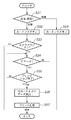
以下、以上の構成に基づく本実施の形態に係るフォトダイレクトプリンタ装置1000における処理を、図7乃至図12に示すフローチャートを参照して説明する。尚、これの処理はDSP3002のCPUにより、マルチタスク処理により実行される。
【0030】
図7は、プリンタ装置1000とデジタルカメラ3012とが接続される場合の処理を示すフローチャートである。
【0031】
ますステップS1で、USBホストタスクにより、USBバスにデジタルカメラ3012が接続されたかどうかを調べる。カメラ3012が接続されたことが検知されるとステップS2に進み、デジタルカメラ3012が接続されたことを示すメモリ3003のカメラフラグをオンにする。次にステップS3に進み、PCカード3011によるプリントモードか、PC3010よりのデータに基づく印刷モードの実行中かどうかをみる。そうでない時、或いは印刷モードの実行中であればそのモードが終了するのを待ってステップS4に進み、操作パネル1010の表示部1006にカメラマーク6000を表示して、ユーザにデジタルカメラ3012が接続されたことを報知する。そしてステップS5に進み、そのデジタルカメラ3012からの画像データの取り込み、及びそのカメラ3012の操作部によりなされる操作指示に従って、そのデジタルカメラ3012で撮像されて、そのカメラ3012の記憶媒体に記憶されている画像のプリント処理を実行する。
【0032】
一方ステップS1でデジタルカメラ3012が接続されたのではなく接続が解除された、即ち、デジタルカメラ3012が切り離されている場合はステップS6に進み、カメラフラグがオンかどうか、即ち、今まで接続されていて、今回、初めてカメラ3012が切り離されたかどうかをみる。そうであればステップS7に進み、カメラフラグをオフにし、ステップS8で表示部1006に表示されていたカメラマーク6000を消去する。そしてステップS9に進み、PCカード3011が装着されていることを示すカードフラグがオンかどうかを調べる。オンであればステップS10に進み、それまで無効にされていたPCカード3011からの画像データの読み出しや、その読み出した画像データの印刷処理などに進む。これは、デジタルカメラ3012が接続されている場合には、PCカード3011からの画像データの読み出しやそれによる印刷処理が実行されずにサスペンドされた状態であるため、これらの処理に移行するためのものである。尚、ステップS6でカメラフラグがオフの場合、或いはステップS9で、カードフラグがオフの場合は、そのまま処理を終了する。
【0033】
図8は、PCカード3011の装着、或いは脱着に伴う処理を説明するフローチャートである。
【0034】
このPCカード3011の着脱は割り込みにより知らされ、まずステップS21で、PCカード3011が装着されたのか、或いは取り外されたのかをみる。装着された場合はステップS22に進み、PCカード3011が装着されたことを示すカードフラグをオンにする。次にステップS23に進み、カメラ3012が接続されているかどうかを、カメラフラグにより判定する。カメラフラグがオンであれば、PCカード3011が装着されたことによる、データの取り込みを行うことなく、そのまま処理を終了する。
【0035】
一方、カメラフラグがオフであればステップS24に進み、PCモード、即ち、PC3010からの印刷指示に従って印刷ジョブを実行中かどうかをみる。そうでなければステップS26に進むが、そうであればステップS25に進み、その印刷ジョブが終了するのを待ってステップS26に進む。ステップS26では、操作パネル1010の操作指示に従って、PCカード3011からのデータの読み出しを行い、ステップS27で、操作パネル1010からの指示に従って、その読み出した画像データを印刷する。
【0036】
またステップS21で、PCカード3011が外された場合はステップS28に進み、カードフラグをオフにして、PCカード3011が取り外されたことを記憶しておく。
【0037】
図9は、PC3010からの印刷データを受信して印刷する処理を説明するフローチャートである。
【0038】
PC3010からの印刷データを受信するとステップS31で、カメラフラグがオンかどうか、即ち、デジタルカメラ3012が接続されているかどうかをみる。接続されている時はステップS32に進み、ビジー信号をPC3010に出力して、PC3010からの画像データを印刷できない旨を知らせる。
【0039】
一方、ステップS31で、カメラフラグがオフの時はステップS33に進み、カードフラグがオンか、即ちPCカード3011が装着されているかをみる。PCカード3011が装着されていない場合はステップS35に進むが、装着されている時はステップS34に進み、PCカード3011からの画像データの印刷処理が実行されているかどうかをみる。印刷処理中であればステップS33に戻って、PCカード3011の画像データの印刷終了を待ってステップS34からステップS35に進み、PC3010からの画像データを受信して印刷する、所謂、通常のPCプリンタとしての動作を実行する。
【0040】
図10は、ビューワ1011への画像表示処理を説明するフローチャートである。
【0041】
ビューワ1011への表示エベントが発生するとステップS41に進み、カメラフラグがオンかどうかをみる。オンでなければステップS42に進み、表示すべきデータをビューワ1011に出力して、表示を指示された画像を表示する。一方、カメラフラグがオン、即ち、デジタルカメラ3012が接続されているときは、何もせずに処理を終了する。
【0042】
これにより、デジタルカメラ3012が接続されているときは、ビューワ1011への画像表示が禁止される。
【0043】
図11は、操作パネル1010との間の入出力制御を示すフローチャートである。
【0044】
操作パネル1010におけるキー入力イベント或いは表示部1006への表示イベントが発生するとステップS51に進み、カメラフラグがオンかどうかをみる。オンでなければステップS52に進み、その発生したキー入力イベント、或いは表示イベントに応じた処理を実行する。一方、カメラフラグがオン、即ち、デジタルカメラ3012が接続されているときはステップS53に進み、表示部1006に前述したカメラマーク6000を表示して処理を終了する。
【0045】
これにより、デジタルカメラ3012が接続されているときは、操作パネル1010におけるキー操作が無視されることになる。
【0046】
また図12は、PC3010からPCカード3011へのアクセスを示すフローチャートである。
【0047】
PC3010からのPCカード3011へのアクセス要求が入力されるとステップS61に進み、カードフラグがオンかどうかをみる。オンでなければPCカード3011が装着されていないので、その旨をPC3010に伝えて処理を終了する。PCカード3011が装着されている時はステップS62に進み、カメラフラグがオンかどうか、即ち、デジタルカメラ3012が接続されているかどうかをみる。接続されている時はステップS63に進み、デジタルカメラ3012との間のデータのやり取りを時分割し、その時分割した時間でPC3010からPCカード3011へのアクセスを許可する。一方、ステップS62で、デジタルカメラ3012が接続されていない時はステップS64に進み、PC3010によるPCカード3011への画像データの書き込み、或いはPCカード3011からの画像データの読み出しを許可する。
【0048】
これにより、デジタルカメラ3012が接続されている状態でも、PC3010からPCカード3011にアクセスすることが可能となる。
【0049】
尚、上記説明では、デジタルカメラが接続された場合に、そのデジタルカメラによる操作を最優先とする場合で説明したが、例えばデジタルカメラ、PCカード、PCのいずれを最優先とするかを任意に設定できるようにしても良い。
【0050】
又或いはデフォルトで、デジタルカメラを最優先に設定しておき、ユーザが手動により、PCカード、或いはPCを最優先に設定できるようにしてもよい。
【0051】
また、ビューワ1011への表示を常にエネーブルにするスイッチ等を設け、デジタルカメラが接続された場合でも、そのカメラからの画像データをビューワ1011に表示できるようにしても良い。このような設定を行うスイッチは、例えば操作パネル1010設けても良く、或いは装置に設けられた他のスイッチ等でも良い。
【0052】
なお本発明は、複数の機器(例えばホストコンピュータ、インターフェース機器、リーダ、プリンタなど)から構成されるシステムに適用しても、一つの機器からなる装置(例えば、複写機、ファクシミリ装置など)に適用してもよい。
【0053】
また、本発明の目的は、前述した実施形態の機能を実現するソフトウェアのプログラムコードを記録した記憶媒体(または記録媒体)を、システムあるいは装置に供給し、そのシステムあるいは装置のコンピュータ(またはCPUやMPU)が記憶媒体に格納されたプログラムコードを読み出し実行することによっても達成される。この場合、記憶媒体から読み出されたプログラムコード自体が前述した実施形態の機能を実現することになり、そのプログラムコードを記憶した記憶媒体は本発明を構成することになる。また、コンピュータが読み出したプログラムコードを実行することにより、前述した実施形態の機能が実現されるだけでなく、そのプログラムコードの指示に基づき、コンピュータ上で稼働しているオペレーティングシステム(OS)などが実際の処理の一部または全部を行い、その処理によって前述した実施形態の機能が実現される場合も含まれる。
【0054】
さらに、記憶媒体から読み出されたプログラムコードが、コンピュータに挿入された機能拡張カードやコンピュータに接続された機能拡張ユニットに備わるメモリに書込まれた後、そのプログラムコードの指示に基づき、その機能拡張カードや機能拡張ユニットに備わるCPUなどが実際の処理の一部または全部を行い、その処理によって前述した実施形態の機能が実現される場合も含まれる。
【0055】
以上説明したように本実施の形態によれば、PC、メモリカード及びデジタルカメラを接続し、それらよりの画像データを入力して印刷するプリンタ装置において、それぞれ優先順位を設けて印刷できるので、ユーザが意図しない機器或いはメモリ等からの画像データを印刷する虞がなくなる。
【0056】
尚、本実施の形態では、撮像装置としてデジタルカメラを例に挙げて説明したが本発明はこれに限られるものではない。例えば、近年においては、撮像機能と撮像して得られた画像データを保存する機能を備えた携帯電話も知られており、本実施の形態で挙げたデジタルカメラの替わりに、そのような携帯電話を、接続ケーブルを介して接続可能な構成としてもよい。
【0057】
また、携帯可能な情報端末として、PDA(Personal Digital Assistance)として、画像を表示可能な液晶モニタや、撮像した画像を保存可能なメモリを備えたものも最近普及しつつあり、このようなPDAを接続ケーブルで接続可能とし、上述の実施の形態のデジタルカメラと同様に、保存されている画像データを記録可能に構成してもよい。
【0058】
また本実施の形態に係るフォトダイレクトプリンタ装置によれば、一台のプリンタ装置で、PCプリンタ、カメラ用のプリンタ、及びメモリプリンタとしての機能を実現できる。
【0059】
【発明の効果】
以上説明したように本発明によれば、撮像装置が接続された場合に、その撮像装置からの画像データを優先的に処理することができる。
【0060】
また本発明によれば、撮像装置が接続された場合に、その撮像装置における操作を有効にし、それ記録装置における操作を無効にすることができる。これにより、複数の機器やメモリが接続された場合でも、ユーザの意図しない画像の印刷を防止できるという効果がある。
【図面の簡単な説明】
【図1】本発明の実施の形態に係るフォトダイレクトプリンタ装置の概観斜視図である。
【図2】本実施の形態に係るフォトダイレクトプリンタ装置の操作パネルの概観図である。
【図3】本実施の形態に係るフォトダイレクトプリンタ装置の制御に係る主要部の構成を示すブロック図である。
【図4】本実施の形態に係るフォトダイレクトプリンタ装置のASICの構成を示すブロック図である。
【図5】本実施の形態に係るフォトダイレクトプリンタ装置とデジタルカメラとを接続した状態を示す図である。
【図6】本実施の形態に係るフォトダイレクトプリンタ装置とデジタルカメラとが接続されたときの操作パネルの表示部への表示例を示す図である。
【図7】本実施の形態に係るフォトダイレクトプリンタ装置とデジタルカメラとが接続される場合の処理を示すフローチャートである。
【図8】本実施の形態に係るフォトダイレクトプリンタ装置における、PCカードの装着、或いは脱着に伴う処理を説明するフローチャートである。
【図9】本実施の形態に係るフォトダイレクトプリンタ装置における、PCからの印刷データを受信して印刷する処理を説明するフローチャートである。
【図10】本実施の形態に係るフォトダイレクトプリンタ装置における、ビューワへの画像表示処理を説明するフローチャートである。
【図11】本実施の形態に係るフォトダイレクトプリンタ装置における操作パネルの入出力制御を示すフローチャートである。
【図12】本実施の形態に係るフォトダイレクトプリンタ装置における、PCからPCカードへのアクセス要求処理を説明するフローチャートである。[0001]
BACKGROUND OF THE INVENTION
The present invention relates to a recording apparatus that inputs image data from an imaging apparatus such as a digital camera or a memory and records it on a recording medium, a control method therefor, and a recording medium.
[0002]
[Prior art]
In recent years, digital cameras (imaging devices), so-called digital cameras, that can take an image with a simple operation and convert it into digital image data have been widely used. When printing an image taken with such a camera and using it as a photograph, the taken digital image data is usually once taken into a PC (computer) from the digital camera, and image processing is performed on the PC. After that, the data is generally output from the PC to a color printer and printed.
[0003]
[Problems to be solved by the invention]
On the other hand, recently, a color print system that can directly transmit digital image data from a digital camera to a color printer for printing without using a PC, and a digital camera that is mounted and stores captured images. A so-called photo direct (PD) printer has been developed in which a memory card is directly attached to a color printer and a photographed image stored in the memory card can be printed.
[0004]
However, since such a photo direct printer can be connected to a camera, a memory card, and even a PC, the operability and erroneous operation of the printer may become a problem when they are connected at the same time.
[0005]
The present invention has been made in view of the above conventional example, and provides a recording apparatus that preferentially processes image data from the imaging apparatus when the imaging apparatus is connected, a control method thereof, and a recording medium. Objective.
[0006]
It is another object of the present invention to provide a recording apparatus, a control method thereof, and a recording medium that enable operations in the imaging apparatus and disable operations in the recording apparatus when the imaging apparatus is connected.
[0007]
[Means for Solving the Problems]
In order to achieve the above object, the recording apparatus of the present invention has the following configuration. That is,
A recording device that records an image based on received image data,
A mounting unit for mounting a storage medium for storing image data;
A terminal for connecting to an imaging device capable of outputting captured image data;
Processing means for processing image data input via the mounting portion and the terminal;
An operation unit that is operated by a user to input commands and data;
Detecting means for detecting whether or not an imaging device is connected via the terminal;
Invalidating means for invalidating input of image data from the storage medium attached to the attachment unit and operation in the operation unit when the detection unit detects that the imaging device is connected;
Recording control means for controlling to record an image based on image data from the imaging device;
Control means for controlling to continue the input of the image data from the storage medium by the invalidating means and the invalid state of the operation in the operation unit while the detecting means detects that the imaging device is connected; ,
It is characterized by having.
[0010]
In order to achieve the above object, a control method for a recording apparatus of the present invention comprises the following steps. That is,
A control method for controlling a recording apparatus for recording an image based on received image data,
A detection step of detecting whether or not the imaging device is connected;
When it is detected that the imaging device is connected in the detection step, an invalidation step of invalidating input of image data from the attached storage medium and user operation in the operation unit,
A recording control step of controlling to record an image based on image data from the imaging device;
A control step for controlling to continue the input of image data from the storage medium in the invalidation step and the invalid state of the operation in the operation unit while detecting that the imaging device is connected in the detection step; ,
It is characterized by having.
[0013]
DETAILED DESCRIPTION OF THE INVENTION
Preferred embodiments of the present invention will be described below in detail with reference to the accompanying drawings.
[0014]
FIG. 1 is a schematic perspective view of a
[0015]
In FIG. 1, the main body that forms the outer shell of the photo
[0016]
One end of the
[0017]
A
[0018]
FIG. 2 is an overview of
[0019]
In the figure, the liquid
[0020]
Next, with reference to FIG. 3, the configuration of the main part relating to the control of the photo direct printer according to the present embodiment will be described. In FIG. 3, the same reference numerals are given to portions common to the above-described drawings, and the description thereof is omitted.
[0021]
In FIG. 3,
[0022]
Note that the exchange of signals between the
[0023]
FIG. 4 is a block diagram showing the configuration of the
[0024]
[0025]
An outline of the operation based on the above configuration will be described below.
<Normal PC printer mode>
This is a print mode in which an image is printed based on print data sent from the
[0026]
In this mode, when data from the
<Direct print mode from PC card>
When the
<Direct print mode from camera>
FIG. 5 is a diagram showing a state in which the photo
[0027]
In the figure, a cable 500 includes a
[0028]
FIG. 6 is a diagram illustrating a display state of the
[0029]
Hereinafter, processing in the photo
[0030]
FIG. 7 is a flowchart illustrating processing when the
[0031]
In step S1, it is checked by the USB host task whether the
[0032]
On the other hand, if the
[0033]
FIG. 8 is a flowchart for explaining processing associated with insertion or removal of the
[0034]
The attachment / detachment of the
[0035]
On the other hand, if the camera flag is off, the process proceeds to step S24 to check whether the print job is being executed in accordance with the PC mode, that is, the print instruction from the
[0036]
If the
[0037]
FIG. 9 is a flowchart for describing processing for receiving print data from the
[0038]
When print data from the
[0039]
On the other hand, when the camera flag is off in step S31, the process proceeds to step S33 to check whether the card flag is on, that is, whether the
[0040]
FIG. 10 is a flowchart for explaining image display processing on the
[0041]
When a display event to the
[0042]
Thereby, when the
[0043]
FIG. 11 is a flowchart showing input / output control with the
[0044]
When a key input event on the
[0045]
Thus, when the
[0046]
FIG. 12 is a flowchart showing access from the
[0047]
When an access request to the
[0048]
Thus, the
[0049]
In the above description, when a digital camera is connected, the operation by the digital camera is given the highest priority. For example, any of the digital camera, the PC card, and the PC is given the highest priority. It may be settable.
[0050]
Alternatively, by default, the digital camera may be set with the highest priority so that the user can manually set the PC card or PC with the highest priority.
[0051]
In addition, a switch or the like that always enables display on the
[0052]
Note that the present invention can be applied to a system (for example, a copier, a facsimile machine, etc.) composed of a single device even if it is applied to a system composed of a plurality of devices (for example, a host computer, interface device, reader, printer, etc.). May be.
[0053]
Another object of the present invention is to supply a storage medium (or recording medium) in which a program code of software that realizes the functions of the above-described embodiments is recorded to a system or apparatus, and the computer (or CPU or CPU) of the system or apparatus. (MPU) can also be achieved by reading and executing the program code stored in the storage medium. In this case, the program code itself read from the storage medium realizes the functions of the above-described embodiment, and the storage medium storing the program code constitutes the present invention. Further, by executing the program code read by the computer, not only the functions of the above-described embodiments are realized, but also an operating system (OS) running on the computer based on the instruction of the program code. A case where part or all of the actual processing is performed and the functions of the above-described embodiments are realized by the processing is also included.
[0054]
Furthermore, after the program code read from the storage medium is written into a memory provided in a function expansion card inserted into the computer or a function expansion unit connected to the computer, the function is based on the instruction of the program code. The case where the CPU of the expansion card or the function expansion unit performs part or all of the actual processing and the functions of the above-described embodiments are realized by the processing is also included.
[0055]
As described above, according to the present embodiment, a printer that connects a PC, a memory card, and a digital camera, inputs image data from them, and prints them can be printed with priority levels. However, there is no risk of printing image data from an unintended device or memory.
[0056]
In the present embodiment, a digital camera has been described as an example of the imaging apparatus, but the present invention is not limited to this. For example, in recent years, a mobile phone having an imaging function and a function of saving image data obtained by imaging is also known. Instead of the digital camera mentioned in this embodiment, such a mobile phone is known. May be configured to be connectable via a connection cable.
[0057]
In addition, as a portable information terminal, a PDA (Personal Digital Assistance), which is equipped with a liquid crystal monitor capable of displaying an image and a memory capable of storing a captured image, is becoming popular recently. Connection may be made with a connection cable, and the stored image data may be recorded in the same manner as the digital camera of the above-described embodiment.
[0058]
In addition, according to the photo direct printer apparatus according to the present embodiment, functions as a PC printer, a camera printer, and a memory printer can be realized with a single printer apparatus.
[0059]
【The invention's effect】
As described above, according to the present invention, when an imaging device is connected, image data from the imaging device can be preferentially processed.
[0060]
Further, according to the present invention, when an imaging device is connected, the operation on the imaging device can be validated and the operation on the recording device can be invalidated. Thereby, even when a plurality of devices and memories are connected, there is an effect that printing of an image unintended by the user can be prevented.
[Brief description of the drawings]
FIG. 1 is a schematic perspective view of a photo direct printer according to an embodiment of the present invention.
FIG. 2 is an overview of an operation panel of the photo direct printer according to the present embodiment.
FIG. 3 is a block diagram showing a configuration of a main part related to control of the photo direct printer according to the present embodiment.
FIG. 4 is a block diagram showing a configuration of an ASIC of the photo direct printer according to the present embodiment.
FIG. 5 is a diagram showing a state in which the photo direct printer according to the present embodiment and a digital camera are connected.
FIG. 6 is a diagram illustrating a display example on the display unit of the operation panel when the photo direct printer according to the present embodiment and a digital camera are connected.
FIG. 7 is a flowchart showing processing when the photo direct printer according to the present embodiment and a digital camera are connected.
FIG. 8 is a flowchart for explaining processing associated with insertion or removal of a PC card in the photo direct printer according to the present embodiment.
FIG. 9 is a flowchart illustrating a process for receiving and printing print data from a PC in the photo direct printer according to the present embodiment.
FIG. 10 is a flowchart illustrating image display processing on a viewer in the photo direct printer according to the present embodiment.
FIG. 11 is a flowchart showing input / output control of the operation panel in the photo direct printer according to the present embodiment.
FIG. 12 is a flowchart illustrating access request processing from a PC to a PC card in the photo direct printer according to the present embodiment.
Claims (12)
画像データを格納する記憶媒体を装着する装着部と、
撮像した画像データを出力可能な撮像装置に接続するための端子と、
前記装着部及び端子を介して入力される画像データを処理する処理手段と、
ユーザにより操作されて命令及びデータを入力するための操作部と、
前記端子を介して撮像装置が接続されたか否かを検知する検知手段と、
前記検知手段により前記撮像装置が接続されたことが検知されると、前記装着部に装着されている前記記憶媒体からの画像データの入力及び前記操作部における操作を無効にする無効化手段と、
前記撮像装置からの画像データに基づいて画像を記録するように制御する記録制御手段と、
前記検知手段で撮像装置が接続されたことを検知している間、前記無効化手段による記憶媒体からの画像データの入力及び前記操作部における操作の無効状態を継続するように制御する制御手段と、
を有することを特徴とする記録装置。A recording device that records an image based on received image data,
A mounting unit for mounting a storage medium for storing image data;
A terminal for connecting to an imaging device capable of outputting captured image data;
Processing means for processing image data input via the mounting portion and the terminal;
An operation unit that is operated by a user to input commands and data;
Detecting means for detecting whether or not an imaging device is connected via the terminal;
Invalidating means for invalidating input of image data from the storage medium attached to the attachment unit and operation in the operation unit when the detection unit detects that the imaging device is connected;
Recording control means for controlling to record an image based on image data from the imaging device;
Control means for controlling to continue the input of the image data from the storage medium by the invalidating means and the invalid state of the operation in the operation unit while the detecting means detects that the imaging device is connected; ,
A recording apparatus comprising:
前記ホストコンピュータによる前記インターフェース手段を介した前記記憶媒体へのアクセスを許可する許可手段とを更に有し、
前記制御手段は、前記検知手段により前記撮像装置が接続されていると検知している間、記憶媒体からの画像データの入力及び前記操作部における操作の無効状態を継続するように前記無効化手段を制御するとともに、前記ホストコンピュータによる前記インターフェース手段を介した前記記憶媒体へのアクセスを許容するように前記許可手段を制御することを特徴とする請求項1に記載の記録装置。Interface means for connecting to a host computer;
Further possess a permission means for permitting access to said storage medium via said interface means by said host computer,
The invalidating means is configured to continue the invalidation state of the input of the image data from the storage medium and the operation of the operation unit while the control means detects that the imaging device is connected by the detecting means. The recording apparatus according to claim 1 , wherein the permission unit is controlled so as to permit access to the storage medium via the interface unit by the host computer .
撮像装置が接続されたか否かを検知する検知工程と、
前記検知工程で前記撮像装置が接続されたことが検知されると、装着されている記憶媒体からの画像データの入力及び操作部におけるユーザ操作を無効にする無効化工程と、
前記撮像装置からの画像データに基づいて画像を記録するように制御する記録制御工程と、
前記検知工程で撮像装置が接続されたことを検知している間、前記無効化工程による記憶媒体からの画像データの入力及び前記操作部における操作の無効状態を継続するように制御する制御工程と、
を有することを特徴とする記録装置の制御方法。A control method for controlling a recording apparatus for recording an image based on received image data,
A detection step of detecting whether or not the imaging device is connected;
When it is detected that the imaging device is connected in the detection step, an invalidation step of invalidating input of image data from the attached storage medium and user operation in the operation unit,
A recording control step of controlling to record an image based on image data from the imaging device;
A control step for controlling to continue the input of image data from the storage medium in the invalidation step and the invalid state of the operation in the operation unit while detecting that the imaging device is connected in the detection step; ,
A control method for a recording apparatus, comprising:
前記制御工程は、前記検知工程で前記撮像装置が接続されていると検知している間、記憶媒体からの画像データの入力及び前記操作部における操作の無効状態を継続するように前記無効化工程を制御するとともに、前記ホストコンピュータによる前記記憶媒体へのアクセスを許容するように前記許可工程を制御することを特徴とする請求項6に記載の記録装置の制御方法。Further have a permission step of permitting access to the storage medium by the host computer,
While the control step detects that the imaging device is connected in the detection step, the invalidation step so as to continue the input of the image data from the storage medium and the invalid state of the operation in the operation unit. 7. The recording apparatus control method according to claim 6 , wherein the permission step is controlled so as to allow access to the storage medium by the host computer .
Priority Applications (8)
| Application Number | Priority Date | Filing Date | Title |
|---|---|---|---|
| JP2001305697A JP4054555B2 (en) | 2001-10-01 | 2001-10-01 | Recording apparatus, control method therefor, and recording medium |
| US10/254,506 US7057750B2 (en) | 2001-10-01 | 2002-09-26 | Printing apparatus, control method therefor, and storage medium |
| AU2002301246A AU2002301246B2 (en) | 2001-10-01 | 2002-09-27 | Printing Apparatus, Control Method Therefor, and Storage Medium |
| KR1020020059084A KR100549744B1 (en) | 2001-10-01 | 2002-09-28 | Printing apparatus, control method therefor, and storage medium |
| CNB021442150A CN1177296C (en) | 2001-10-01 | 2002-09-29 | Recording device and control method and recording medium |
| EP02021992A EP1301020B1 (en) | 2001-10-01 | 2002-09-30 | Printing apparatus, control method therefor, and storage medium |
| DE60220231T DE60220231T2 (en) | 2001-10-01 | 2002-09-30 | Image printing apparatus, control method therefor and storage medium |
| CA002406351A CA2406351C (en) | 2001-10-01 | 2002-10-01 | Printing apparatus, control method therefor and storage medium |
Applications Claiming Priority (1)
| Application Number | Priority Date | Filing Date | Title |
|---|---|---|---|
| JP2001305697A JP4054555B2 (en) | 2001-10-01 | 2001-10-01 | Recording apparatus, control method therefor, and recording medium |
Publications (2)
| Publication Number | Publication Date |
|---|---|
| JP2003103883A JP2003103883A (en) | 2003-04-09 |
| JP4054555B2 true JP4054555B2 (en) | 2008-02-27 |
Family
ID=19125447
Family Applications (1)
| Application Number | Title | Priority Date | Filing Date |
|---|---|---|---|
| JP2001305697A Expired - Fee Related JP4054555B2 (en) | 2001-10-01 | 2001-10-01 | Recording apparatus, control method therefor, and recording medium |
Country Status (8)
| Country | Link |
|---|---|
| US (1) | US7057750B2 (en) |
| EP (1) | EP1301020B1 (en) |
| JP (1) | JP4054555B2 (en) |
| KR (1) | KR100549744B1 (en) |
| CN (1) | CN1177296C (en) |
| AU (1) | AU2002301246B2 (en) |
| CA (1) | CA2406351C (en) |
| DE (1) | DE60220231T2 (en) |
Families Citing this family (19)
| Publication number | Priority date | Publication date | Assignee | Title |
|---|---|---|---|---|
| US6628194B1 (en) * | 1999-08-31 | 2003-09-30 | At&T Wireless Services, Inc. | Filtered in-box for voice mail, e-mail, pages, web-based information, and faxes |
| WO2003076199A1 (en) * | 2002-03-14 | 2003-09-18 | Seiko Epson Corporation | Printer and printer control method |
| KR100484176B1 (en) * | 2002-11-08 | 2005-04-18 | 삼성전자주식회사 | Method and apparatus for controlling an image display |
| JP2004310672A (en) | 2003-04-10 | 2004-11-04 | Seiko Epson Corp | Data input device and image output system |
| JP2005066988A (en) * | 2003-08-22 | 2005-03-17 | Canon Inc | Image feeder, recorder, recording system and its controlling method and program |
| US7489417B2 (en) | 2003-09-30 | 2009-02-10 | Toshiba Corporation | USB print |
| US7554680B2 (en) | 2003-10-01 | 2009-06-30 | Seiko Epson Corporation | Printer equipped with display for displaying menu screens for setting printing conditions |
| US7448734B2 (en) * | 2004-01-21 | 2008-11-11 | Silverbrook Research Pty Ltd | Inkjet printer cartridge with pagewidth printhead |
| US20050157112A1 (en) | 2004-01-21 | 2005-07-21 | Silverbrook Research Pty Ltd | Inkjet printer cradle with shaped recess for receiving a printer cartridge |
| US20050185205A1 (en) * | 2004-02-20 | 2005-08-25 | Neal Eckhaus | Digital printer for transferring and printing images from a digital camera and a computer |
| JP4700943B2 (en) | 2004-09-06 | 2011-06-15 | キヤノン株式会社 | Information processing apparatus, control method therefor, and program |
| US20060067723A1 (en) * | 2004-09-30 | 2006-03-30 | James Edmund H Iii | Operator module configured for detachable attachment to an imaging apparatus |
| JP2007083620A (en) * | 2005-09-22 | 2007-04-05 | Fuji Xerox Co Ltd | Image forming apparatus and its control method |
| JP5133516B2 (en) * | 2005-11-14 | 2013-01-30 | コニカミノルタビジネステクノロジーズ株式会社 | Menu display device, menu display method, and menu display program |
| JP2007179208A (en) * | 2005-12-27 | 2007-07-12 | Noritsu Koki Co Ltd | Image processing device |
| JP2008105406A (en) * | 2006-09-28 | 2008-05-08 | Brother Ind Ltd | Image formation apparatus |
| US8864296B2 (en) * | 2008-01-30 | 2014-10-21 | Hewlett-Packard Development Company, L.P. | System for priming a fluid dispenser by expanding gas bubbles |
| CN107116911A (en) * | 2017-03-28 | 2017-09-01 | 温州走着瞧科技有限公司 | The ink-jet flat board printing device of detection can be automatically positioned |
| KR20220170422A (en) | 2021-06-23 | 2022-12-30 | 민맥스 주식회사 | Regenerative electronic load smart parallel control system |
Family Cites Families (12)
| Publication number | Priority date | Publication date | Assignee | Title |
|---|---|---|---|---|
| WO1997050243A1 (en) | 1996-06-25 | 1997-12-31 | Casio Computer Co., Ltd. | Printing apparatus and printing system |
| GB9626891D0 (en) | 1996-12-24 | 1997-02-12 | Rue Fortronic De Limited | Memory card reading terminal |
| US6573927B2 (en) | 1997-02-20 | 2003-06-03 | Eastman Kodak Company | Electronic still camera for capturing digital image and creating a print order |
| DE69835179T2 (en) * | 1997-03-12 | 2007-07-05 | Canon K.K. | Method, system and device for data transmission and program for data transmission method stored in a storage medium |
| JP3880123B2 (en) | 1997-03-12 | 2007-02-14 | キヤノン株式会社 | Data communication device |
| JPH118792A (en) | 1997-06-13 | 1999-01-12 | Kyocera Corp | Digital camera system which can integrally be connected with printer |
| JPH11138911A (en) * | 1997-11-07 | 1999-05-25 | F & F:Kk | Printer |
| US6356357B1 (en) * | 1998-06-30 | 2002-03-12 | Flashpoint Technology, Inc. | Method and system for a multi-tasking printer capable of printing and processing image data |
| JP2000177210A (en) * | 1998-12-17 | 2000-06-27 | Olympus Optical Co Ltd | Storage built-in printer |
| JP2000280583A (en) * | 1999-04-01 | 2000-10-10 | Toshiba Tec Corp | Imaging apparatus |
| KR100351664B1 (en) | 1999-07-14 | 2002-09-11 | 가시오게산키 가부시키가이샤 | Customer terminal apparatus, its system, and recording medium which records that program |
| JP2001156987A (en) | 1999-11-30 | 2001-06-08 | Canon Inc | System and method for forming image and storage medium |
-
2001
- 2001-10-01 JP JP2001305697A patent/JP4054555B2/en not_active Expired - Fee Related
-
2002
- 2002-09-26 US US10/254,506 patent/US7057750B2/en not_active Expired - Fee Related
- 2002-09-27 AU AU2002301246A patent/AU2002301246B2/en not_active Ceased
- 2002-09-28 KR KR1020020059084A patent/KR100549744B1/en not_active IP Right Cessation
- 2002-09-29 CN CNB021442150A patent/CN1177296C/en not_active Expired - Fee Related
- 2002-09-30 EP EP02021992A patent/EP1301020B1/en not_active Expired - Lifetime
- 2002-09-30 DE DE60220231T patent/DE60220231T2/en not_active Expired - Lifetime
- 2002-10-01 CA CA002406351A patent/CA2406351C/en not_active Expired - Fee Related
Also Published As
| Publication number | Publication date |
|---|---|
| CA2406351C (en) | 2008-07-22 |
| KR100549744B1 (en) | 2006-02-08 |
| JP2003103883A (en) | 2003-04-09 |
| EP1301020B1 (en) | 2007-05-23 |
| EP1301020A3 (en) | 2003-08-13 |
| CN1412717A (en) | 2003-04-23 |
| DE60220231T2 (en) | 2008-01-17 |
| US20030063148A1 (en) | 2003-04-03 |
| EP1301020A2 (en) | 2003-04-09 |
| CN1177296C (en) | 2004-11-24 |
| US7057750B2 (en) | 2006-06-06 |
| AU2002301246B2 (en) | 2008-06-26 |
| DE60220231D1 (en) | 2007-07-05 |
| CA2406351A1 (en) | 2003-04-01 |
| KR20030028411A (en) | 2003-04-08 |
Similar Documents
| Publication | Publication Date | Title |
|---|---|---|
| JP4054555B2 (en) | Recording apparatus, control method therefor, and recording medium | |
| US7224480B2 (en) | Imaging apparatus, system having imaging apparatus and printing apparatus, and control method therefor | |
| JP3884942B2 (en) | IMAGING DEVICE, SYSTEM HAVING IMAGING DEVICE AND RECORDING DEVICE AND CONTROL METHOD THEREOF | |
| JP3496009B2 (en) | Recording apparatus, control method therefor, and program | |
| JP4208640B2 (en) | Printing system, printing control method, printing apparatus, and control method therefor | |
| JP4027161B2 (en) | Printer apparatus and control method thereof | |
| JP3848130B2 (en) | IMAGING DEVICE, SYSTEM HAVING IMAGING DEVICE AND RECORDING DEVICE AND CONTROL METHOD THEREOF | |
| JP2004009388A (en) | Printing equipment and its control process as well as printing system | |
| JP4371632B2 (en) | Image recording apparatus and recording control method therefor | |
| JP2004072350A (en) | Digital camera and printer | |
| JP4143501B2 (en) | Image supply apparatus, recording system including the image supply apparatus and recording apparatus, and communication control method thereof | |
| JP2008288906A (en) | Print system, and control method and program therefor | |
| JP2007164340A (en) | Print system and method for controlling print system | |
| JP2005161592A (en) | Printing apparatus | |
| JP4125018B2 (en) | Image recording apparatus, image processing apparatus, and control method thereof | |
| JP2006171812A (en) | Image output system | |
| JP2003246120A (en) | Control method for image recorder and image recording system | |
| JP4047147B2 (en) | Recording apparatus and control method thereof | |
| JP2008254382A (en) | Printing apparatus, controlling method of the same, and program | |
| JP2004009316A (en) | Direct printer | |
| JP2006168079A (en) | Recording system and method for recording it, image feeding apparatus and method for controlling it, recording apparatus and method for controlling it, program, and storing medium | |
| JP2006005760A (en) | Recording device, imaging device, and printing system | |
| JP4612907B2 (en) | Image supply apparatus and control method thereof | |
| JP2005167559A (en) | Print system | |
| JP2004193869A (en) | Recorder |
Legal Events
| Date | Code | Title | Description |
|---|---|---|---|
| A621 | Written request for application examination |
Free format text: JAPANESE INTERMEDIATE CODE: A621 Effective date: 20040916 |
|
| A977 | Report on retrieval |
Free format text: JAPANESE INTERMEDIATE CODE: A971007 Effective date: 20060511 |
|
| A131 | Notification of reasons for refusal |
Free format text: JAPANESE INTERMEDIATE CODE: A131 Effective date: 20061106 |
|
| A521 | Request for written amendment filed |
Free format text: JAPANESE INTERMEDIATE CODE: A523 Effective date: 20061227 |
|
| TRDD | Decision of grant or rejection written | ||
| A01 | Written decision to grant a patent or to grant a registration (utility model) |
Free format text: JAPANESE INTERMEDIATE CODE: A01 Effective date: 20071203 |
|
| A61 | First payment of annual fees (during grant procedure) |
Free format text: JAPANESE INTERMEDIATE CODE: A61 Effective date: 20071210 |
|
| FPAY | Renewal fee payment (event date is renewal date of database) |
Free format text: PAYMENT UNTIL: 20101214 Year of fee payment: 3 |
|
| R150 | Certificate of patent or registration of utility model |
Free format text: JAPANESE INTERMEDIATE CODE: R150 |
|
| FPAY | Renewal fee payment (event date is renewal date of database) |
Free format text: PAYMENT UNTIL: 20111214 Year of fee payment: 4 |
|
| FPAY | Renewal fee payment (event date is renewal date of database) |
Free format text: PAYMENT UNTIL: 20121214 Year of fee payment: 5 |
|
| FPAY | Renewal fee payment (event date is renewal date of database) |
Free format text: PAYMENT UNTIL: 20131214 Year of fee payment: 6 |
|
| LAPS | Cancellation because of no payment of annual fees |