JP4371632B2 - Image recording apparatus and recording control method therefor - Google Patents
Image recording apparatus and recording control method therefor Download PDFInfo
- Publication number
- JP4371632B2 JP4371632B2 JP2002164623A JP2002164623A JP4371632B2 JP 4371632 B2 JP4371632 B2 JP 4371632B2 JP 2002164623 A JP2002164623 A JP 2002164623A JP 2002164623 A JP2002164623 A JP 2002164623A JP 4371632 B2 JP4371632 B2 JP 4371632B2
- Authority
- JP
- Japan
- Prior art keywords
- image data
- compressed image
- recording
- data
- memory
- Prior art date
- Legal status (The legal status is an assumption and is not a legal conclusion. Google has not performed a legal analysis and makes no representation as to the accuracy of the status listed.)
- Expired - Fee Related
Links
Images


Classifications
-
- G—PHYSICS
- G06—COMPUTING; CALCULATING OR COUNTING
- G06F—ELECTRIC DIGITAL DATA PROCESSING
- G06F3/00—Input arrangements for transferring data to be processed into a form capable of being handled by the computer; Output arrangements for transferring data from processing unit to output unit, e.g. interface arrangements
- G06F3/12—Digital output to print unit, e.g. line printer, chain printer
-
- H—ELECTRICITY
- H04—ELECTRIC COMMUNICATION TECHNIQUE
- H04N—PICTORIAL COMMUNICATION, e.g. TELEVISION
- H04N1/00—Scanning, transmission or reproduction of documents or the like, e.g. facsimile transmission; Details thereof
- H04N1/00127—Connection or combination of a still picture apparatus with another apparatus, e.g. for storage, processing or transmission of still picture signals or of information associated with a still picture
- H04N1/00278—Connection or combination of a still picture apparatus with another apparatus, e.g. for storage, processing or transmission of still picture signals or of information associated with a still picture with a printing apparatus, e.g. a laser beam printer
-
- H—ELECTRICITY
- H04—ELECTRIC COMMUNICATION TECHNIQUE
- H04N—PICTORIAL COMMUNICATION, e.g. TELEVISION
- H04N2201/00—Indexing scheme relating to scanning, transmission or reproduction of documents or the like, and to details thereof
- H04N2201/0008—Connection or combination of a still picture apparatus with another apparatus
- H04N2201/0015—Control of image communication with the connected apparatus, e.g. signalling capability
-
- H—ELECTRICITY
- H04—ELECTRIC COMMUNICATION TECHNIQUE
- H04N—PICTORIAL COMMUNICATION, e.g. TELEVISION
- H04N2201/00—Indexing scheme relating to scanning, transmission or reproduction of documents or the like, and to details thereof
- H04N2201/0008—Connection or combination of a still picture apparatus with another apparatus
- H04N2201/0034—Details of the connection, e.g. connector, interface
- H04N2201/0037—Topological details of the connection
- H04N2201/0041—Point to point
-
- H—ELECTRICITY
- H04—ELECTRIC COMMUNICATION TECHNIQUE
- H04N—PICTORIAL COMMUNICATION, e.g. TELEVISION
- H04N2201/00—Indexing scheme relating to scanning, transmission or reproduction of documents or the like, and to details thereof
- H04N2201/0008—Connection or combination of a still picture apparatus with another apparatus
- H04N2201/0034—Details of the connection, e.g. connector, interface
- H04N2201/0048—Type of connection
- H04N2201/0049—By wire, cable or the like
-
- H—ELECTRICITY
- H04—ELECTRIC COMMUNICATION TECHNIQUE
- H04N—PICTORIAL COMMUNICATION, e.g. TELEVISION
- H04N2201/00—Indexing scheme relating to scanning, transmission or reproduction of documents or the like, and to details thereof
- H04N2201/0077—Types of the still picture apparatus
- H04N2201/0084—Digital still camera
Description
【0001】
【発明の属する技術分野】
本発明は、例えばデジタルカメラ等で撮影された画像データを入力して記録媒体に記録する画像記録装置及びその記録制御方法に関するものである。
【0002】
【従来の技術】
近年、簡単な操作で画像を撮影してデジタル画像データに変換できるデジタルカメラ(撮像装置)、所謂、デジカメが広く使用されるようになってきている。このようなカメラで撮影した画像を印刷して写真として使用する場合には、通常、一旦、その撮影されたデジタル画像データを、デジタルカメラからPC(コンピュータ)に取り込み、そのPCで画像処理を行った後、そのPCからカラープリンタに出力して印刷するのが一般的である。
【0003】
これに対して最近は、PCを介することなく、直接、デジタルカメラからカラープリンタにデジタル画像データを伝送して印刷することができるカラープリントシステムや、デジタルカメラに搭載され、撮像した画像を記憶しているメモリカードを、直接、カラープリンタに装着し、そのメモリカードに記憶されている、撮影された画像を印刷できる、所謂フォトダイレクト(PD)プリンタ等も開発されている。
【0004】
デジタルカメラに格納されている画像データは、一般的にはJPEG等により圧縮されており、上述のPDプリンタ装置は、この圧縮画像データを入力しバッファに格納した後、それを伸張して印刷を行っている。このような圧縮画像データを入力し、それを伸張して印刷する場合の伸張方法として、例えば特開平10−262249号公報「圧縮画像データの伸張方法及び装置」がある。これによると、圧縮画像データとして蓄積された以外の順序で、MCU単位に画像データを取り出すことが記載されている。この方法を用いれば、1画面分の画像出力バッファを準備する必要がなく画像データの伸張処理に要するメモリサイズを縮小できるという利点がある。但し、この発明が有効なものとなる前提として、データの読み出し速度が十分に速いという要件が必要になる。これは、十分に速いアクセス速度が得られる場合は、頻繁にMCU単位でのデータのアクセスを行っても、その画像データを伸張して出力する速度に与える影響は少ないと考えられる。
【0005】
【発明が解決しようとする課題】
しかしながら上記従来例では、MCU単位での画像データのアクセスが頻繁に発生するために、画像ファイルなどへのリード、シークが十分に高速に行えない場合には、その画像データが印刷されるまでの時間が著しく長くなる。即ち、圧縮画像データを伸張処理前に1度読み取り、1画面中のMCU毎の符号化ビット長情報を求め、所定の順にMCU単位で圧縮画像の伸張処理を行うため、画像データの先端部から後端部にかけてランダムに、画像データへのアクセスが発生する。また、画像データのサイズが、そのPDプリンタ装置のメモリサイズを超えている場合は、単純に画像データの先頭からバッファリングを行っただけでは、最後の画像データ部分がバッファリングできない。このため、そのバッファメモリのサイズを越えた画像データ部分を印刷する際には、更にカメラにそのデータを要求して取得するためのアクセスが必要になり、よりアクセス速度の遅さの影響が出てしまう。
【0006】
この問題点を図11及び図12を参照して詳しく説明する。
【0007】
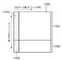
図11は、ラスタ走査順に圧縮されたJPEGデータをその順序で受信してイメージ展開した場合の、イメージメモリにおける画像データの存在域(斜線部)を示す図で、図示のように、イメージ展開された画像データは、その水平方向の長さがそれぞれ異なっている。ここでプリンタ装置のメモリ容量を抑えて製品のコストダウンを図るために、このイメージメモリのメモリ容量はイメージデータ全体を格納できる容量以下に設定されている。図において、10000で示す部分がイメージメモリに格納可能な範囲とする。
【0008】
また、プリントヘッドの走査範囲を狭くして製品の小型化を図りながら、より大きな画像の印刷出力を可能にするために、図11におけるような横長の画像に対して垂直方向に画像を印刷する方法が用いられている。
【0009】
従って、図12のように、11000で示す画像データを、ラスタ順、即ち、JPEGデータの順に格納して展開すると、11001で示す部分がイメージメモリのメモリ容量内に含まれ、11002で示す部分がはみ出してしまい、記憶されなくなる。ここで、キャリッジ(プリントヘッド)の走査方向は垂直方向であるため、最初のヘッド走査で印刷されるデータ部分(斜線部:11003+11004)の内、11004で示すデータ部分がイメージメモリに格納されていないため、この印刷走査のためには、更にデジタルカメラに対して、この部分11004に対応するJPEGデータを要求し、それを受取って復号してイメージ展開する必要が生じる。このような処理は画像データの印刷に要する時間を長くし、ユーザにとって極めて使いずらいものとなっていた。
【0010】
本発明は上記従来例に鑑みてなされたもので、画像データを撮像装置から効率良く取得してメモリに記憶し、撮像装置からの画像データの転送回数を減らして画像の記録に要する時間を短縮する画像記録装置及びその画像記録制御方法を提供することを目的とする。
【0011】
また本発明の目的は、少ないメモリ容量の場合でも、画像データを効率良く記憶して画像データの転送回数を減らし、画像の記録に要する時間を短縮できるようにした画像記録装置及びその画像記録制御方法を提供することにある。
【0012】
【課題を解決するための手段】
上記目的を達成するために本発明の画像記録装置は以下のような構成を備える。即ち、
撮像装置からの圧縮画像データを受信して記録する画像記録装置であって、
記録ヘッドを走査して記録する記録手段と、
メモリの領域を複数のブロックに分割し、受信した圧縮画像データを前記ブロック単位で当該メモリに記憶する記憶制御手段と、
前記メモリに記憶されている前記圧縮画像データを伸張してイメージデータに展開する展開手段と、
前記記録ヘッドの一走査で記録される分の圧縮画像データが前記メモリに記憶されているかどうかを判定する判定手段と、
前記判定手段により前記メモリに記憶されていないと判定されると、前記記録ヘッドの一走査で記録される分の圧縮画像データに加えて、少なくとも1つ以上の前記ブロックに相当する圧縮画像データを前記撮像装置に要求する要求手段と、を有することを特徴とする。
【0013】
上記目的を達成するために本発明の画像記録制御方法は以下のような工程を備える。即ち、
撮像装置からの圧縮画像データを受信して記録する画像記録装置における画像記録制御方法であって、
記録ヘッドを走査して記録する記録工程と、
メモリの領域を複数のブロックに分割し、受信した圧縮画像データを前記ブロック単位で当該メモリに記憶する記憶制御工程と、
前記メモリに記憶されている前記圧縮画像データを伸張してイメージデータに展開する展開工程と、
前記記録ヘッドの一走査で記録される分の圧縮画像データが前記メモリに記憶されているかどうかを判定する判定工程と、
前記判定工程で前記メモリに記憶されていないと判定されると、前記記録ヘッドの一走査で記録される分の圧縮画像データに加えて、少なくとも1つ以上の前記ブロックに相当する圧縮画像データを前記撮像装置に要求する要求工程と、を有することを特徴とする。
【0014】
【発明の実施の形態】
以下、添付図面を参照して本発明の好適な実施の形態を詳細に説明する。
【0015】
図1は、本発明の実施の形態に係るフォトダイレクトプリンタ装置(以下、PDプリンタ装置)1000の概観斜視図である。このPDプリンタ装置1000は、ホストコンピュータ(PC)からデータを受信して印刷する通常のPCプリンタとしての機能と、メモリカードなどの記憶媒体に記憶されている画像データを直接読取って印刷したり、或いはデジタルカメラからの画像データを受信して印刷する機能を備えている。
【0016】
図1において、本実施の形態に係るPDプリンタ装置1000の外殻をなす本体は、ケースM1001、上ケース1002、アクセスカバー1003及び排出トレイ1004の外装部材を有している。また、下ケース1001は、PDプリンタ装置1000の略下半部を、上ケース1002は本体の略上半部をそれぞれ形成しており、両ケースの組合せによって内部に後述の各機構を収納する収納空間を有する中空体構造をなし、その上面部及び前面部にはそれぞれ開口部が形成されている。さらに、排出トレイ1004は、その一端部が下ケース1001に回転自在に保持され、その回転によって下ケース1001の前面部に形成される開口部を開閉させ得るようになっている。このため、記録動作を実行させる際には、排出トレイ1004を前面側へと回転させて開口部を開成させることにより、ここから記録シートが排出可能となると共に、排出された記録シートを順次積載し得るようになっている。また、排紙トレイ1004には、2枚の補助トレイ1004a,1004bが収納されており、必要に応じて各トレイを手前に引き出すことにより、用紙の支持面積を3段階に拡大、縮小させ得るようになっている。
【0017】
アクセスカバー1003は、その一端部が上ケース1002に回転自在に保持され、上面に形成される開口部を開閉し得るようになっており、このアクセスカバー1003を開くことによって本体内部に収納されている記録ヘッドカートリッジ(不図示)あるいはインクタンク(不図示)等の交換が可能となる。なお、ここでは特に図示しないが、アクセスカバー1003を開閉させると、その裏面に形成された突起がカバー開閉レバーを回転させるようになっており、そのレバーの回転位置をマイクロスイッチなどで検出することにより、アクセスカバーの開閉状態を検出し得るようになっている。
【0018】
また、上ケース1002の上面には、電源キー1005が押下可能に設けられている。また、上ケース1002の右側には、液晶表示部1006や各種キースイッチ等を備える操作パネル1010が設けられている。この操作パネル1010の構造は、図2を参照して詳しく後述する。1007は自動給送部で、記録シートを装置本体内へと自動的に給送する。1008は紙間選択レバーで、プリントヘッドと記録シートとの間隔を調整するためのレバーである。1009はカードスロットで、ここにメモリカードを装着可能なアダプタが挿入され、このアダプタを介してメモリカードに記憶されている画像データを直接取り込んで印刷することができる。このメモリカード(PC)としては、例えばコンパクトフラッシュ(登録商標)メモリ、スマートメディア、メモリスティック等がある。1011はビューワ(液晶表示部)で、このPDプリンタ装置1000の本体に着脱可能であり、PCカードに記憶されている画像の中からプリントしたい画像を検索する場合などに、1コマ毎の画像やインデックス画像などを表示するのに使用される。1012は後述するデジタルカメラを接続するためのUSB端子である。また、このPD装置1000の後面には、パーソナルコンピュータ(PC)を接続するためのUSBコネクタが設けられている。
【0019】
図2は、本実施の形態に係るPDプリンタ装置1000の操作パネル1010の概観図である。
【0020】
図において、液晶表示部1006には、その左右に印刷されている項目に関するデータを各種設定するためのメニュー項目が表示される。ここに表示される項目としては、例えば、印刷したい範囲の先頭写真番号、指定コマ番号(開始コマ指定/印刷コマ指定)、印刷を終了した範囲の最後の写真番号(終了)、印刷部数(部数)、印刷に使用する用紙(記録シート)の種類(用紙種類)、1枚の用紙に印刷する写真の枚数設定(レイアウト)、印刷の品位の指定(品位)、撮影した日付を印刷するかどうかの指定(日付印刷)、写真を補正して印刷するかどうかの指定(画像補正)、印刷に必要な用紙枚数の表示(用紙枚数)等がある。これら各項目は、カーソルキー2001を用いて選択、或いは指定される。2002はモードキーで、このキーを押下する毎に、印刷の種類(インデックス印刷、全コマ印刷、1コマ印刷等)を切り替えることができ、これに応じてLED2003の対応するLEDが点灯される。2004はメンテナンスキーで、プリントヘッドのクリーニング等、プリンタのメンテナンスを行わせるためのキーである。2005は印刷開始キーで、印刷の開始を指示する時、或いはメンテナンスの設定を確立する際に押下される。2006は印刷中止キーで、印刷を中止させる時や、メンテナンスの中止を指示する際に押下される。
【0021】
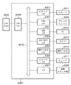
次に図3を参照して、本実施の形態に係るPDプリンタ装置1000の制御に係る主要部の構成を説明する。尚、この図3において、前述の図面と共通する部分は同じ記号を付与して、それらの説明を省略する。
【0022】
図3において、3000は制御部(制御基板)を示している。3001はASIC(専用カスタムLSI)を示し、その構成は図4のブロック図を参照して詳しく後述する。3002はDSP(デジタル信号処理プロセッサ)で、内部にCPUを有し、後述する各種制御処理及び、輝度信号(RGB)から濃度信号(CMYK)への変換、スケーリング、ガンマ変換、誤差拡散等の画像処理等を担当している。3003はメモリで、DSP3002のCPUの制御プログラムを記憶するプログラムメモリ3003a、及び実行時のプログラムを記憶するRAMエリア、画像データなどを記憶するワークメモリとして機能するメモリエリアを有している。3004はプリンタエンジンで、ここでは、複数色のカラーインクを用いてカラー画像を印刷するインクジェットプリンタのプリンタエンジンが搭載されている。3005はデジタルカメラ(DSC)3012を接続するためのポートとしてのUSBコネクタである。3006はビューワ1011を接続するためのコネクタである。3008はUSBハブ(USB HUB)で、このPDプリンタ装置1000がPC3010からの画像データに基づいて印刷を行う際には、PC3010からのデータをそのままスルーし、USB3021を介してプリンタエンジン3004に出力する。これにより、接続されているPC3010は、プリンタエンジン3004と直接、データや信号のやり取りを行って印刷を実行することができる(一般的なPCプリンタとして機能する)。3009は電源コネクタで、電源3011により、商用ACから変換された直流電圧を入力している。PC3010は一般的なパーソナルコンピュータ、3011は前述したメモリカード(PCカード)、3012はデジタルカメラ(DSC:Digital Still Camera)である。
【0023】
尚、この制御部3000とプリンタエンジン3004との間の信号のやり取りは、前述したUSB3021又はIEEE1284バス3022を介して行われる。
【0024】
図4は、ASIC3001の構成を示すブロック図で、この図4においても、前述の図面と共通する部分は同じ記号を付与して、それらの説明を省略する。
【0025】
4001はPCカードインターフェース部で、装着されたPCカード3011に記憶されている画像データを読取ったり、或いはPCカード3011へのデータの書き込み等を行う。4002はIEEE1284インターフェース部で、プリンタエンジン3004との間のデータのやり取りを行う。このIEEE1284インターフェース部4002は、デジタルカメラ3012或いはPCカード3011に記憶されている画像データを印刷する場合に使用されるバスである。4003はUSBインターフェース部で、PC3010との間でのデータのやり取りを行う。4004はUSBホストインターフェース部で、デジタルカメラ3012との間でのデータのやり取りを行う。4005は操作パネル・インターフェース部で、操作パネル1010からの各種操作信号を入力したり、表示部1006への表示データの出力などを行う。4006はビューワ・インターフェース部で、ビューワ1011への画像データの表示を制御している。4007は各種スイッチやLED4009等との間のインターフェースを制御するインターフェース部である。4008はCPUインターフェース部で、DSP3002との間でのデータのやり取りの制御を行っている。4010はこれら各部を接続する内部バス(ASICバス)である。
【0026】
図5は、本実施の形態に係るフォトダイレクトプリンタ装置1000の画像処理制御に係る機能構成をより詳しく示す機能ブロック図である。尚、この図8においても、前述の図面と共通する部分は同じ記号を付与して、それらの説明を省略する。
【0027】
図5において、USBバスインターフェース等のインターフェース部7005を介して入力されたPCカード3011、カメラ3012或はPC3010からの画像データ或はJPEG圧縮された画像データは、一旦入力バッファ7000に格納され、圧縮されたデータの場合はJPEG解凍部(JPEGデコーダ)7006により解凍され、Y,Cb,Cr信号からRGB信号に変換された後、RGBバッファ7001に格納される。7010はX,Yスケーリング部で、RGBバッファ7001に格納された画像データのX及び/又はY方向のサイズを変換する。3D3(7007)は、ルックアップテーブル7009を参照してRGBデータの色空間を変換する。また3D6(7008)は、ルックアップテーブル7009を参照して、RGB信号をC,M,Y,K,LC(明るいシアン),LM(明るいマゼンタ)の6色の信号に変換する。7011は1D出力部で、一次元テーブル7012を参照してγ変換等の色処理を実行する。7012は誤差拡散(ED)部で、多値画像データに対して誤差拡散処理を実行して、各色の2値画像データ(或は多値データ)を生成する。こうして生成された2値(或は多値)画像データは、EDバッファ7003に格納される。7004はワークバッファで、各色のインクを吐出する複数の記録ヘッドのそれぞれに対応する記録データを記憶している。こうして作成された各記録ヘッドに対応する記録データはプリンタインターフェース7013を介してプリンタエンジン3004に送られて印刷される。
【0028】
以上の構成に基づく動作概要を以下に説明する。
【0029】
<通常のPCプリンタモード>
これはPC3010から送られてくる印刷データに基づいて画像を印刷する印刷モードである。
【0030】
このモードでは、PC3010からのデータがUSBコネクタ1013(図3)を介して入力されると、USBハブ3008、USB3021を介して直接プリンタエンジン3004に送られ、PC3010からのデータに基づいて印刷が行われる。
【0031】
<PCカードからの直接プリントモード>
PCカード3011がカードスロット1009に装着或いは脱着されると割り込みが発生し、これによりDSP3002はPCカード3011が装着されたか或いは脱着(取り外された)されたかを検知できる。PCカード3011が装着されると、そのPCカード3011に記憶されている圧縮された(例えばJPEG圧縮)画像データを読込んでメモリ3003に記憶する。その後、その圧縮された画像データを解凍して再度メモリ3003に格納する。次に、操作パネル101を使用して、その格納した画像データの印刷が指示されると、RGB信号からYMCK信号への変換、ガンマ補正、誤差拡散等を実行してプリンタエンジン3004で印刷可能な記録データに変換し、IEEE1284インターフェース部4002を介してプリンタエンジン3004に出力することにより印刷を行う。
【0032】
<カメラからの直接プリントモード>
図6は本実施の形態に係るPDプリンタ装置1000とデジタルカメラ3012とを接続した状態を示す図である。
【0033】
図において、ケーブル5000は、PDプリンタ装置1000のコネクタ1012と接続されるコネクタ5001と、デジタルカメラ3012の接続用コネクタ5003と接続するためのコネクタ5002とを備えており、また、デジタルカメラ3012は、内部のメモリに保存している画像データを、接続用コネクタ5003を介して出力可能に構成されている。なお、デジタルカメラ3012の構成としては、内部に記憶手段としてのメモリを備えるものや、取外し可能なメモリを装着するためのスロットを備えたものなど、種々の構成を採用することができる。このように、図6に示すケーブル5000を介してPDプリンタ装置1000とデジタルカメラ3012とを接続することにより、デジタルカメラ3012からの画像データを直接PDプリンタ装置1000で印刷することができる。
【0034】
ここで図6に示すように、PDプリンタ装置1000にデジタルカメラ3012が接続された場合は、操作パネル1010の表示部1006にはカメラマークのみが表示され、操作パネル1010における表示及び操作が無効になり、又ビューワ1011への表示も無効になる。従って、これ以降はデジタルカメラ3012でのキー操作及びデジタルカメラ3012の表示部(不図示)への画像表示のみが有効になるので、ユーザはそのデジタルカメラ3012を使用して印刷指定を行うことができる。
【0035】
以下、本実施の形態の特徴部分について説明する。
【0036】
図7(A)〜(C)は、デジタルカメラ3012からJPEGデータを受信して記憶する入力バッファ7000の中の画像データを格納するメモリエリアの構成を説明する図である。この入力バッファ7000は、受信したJPEGデータを記憶しており、JPEG解凍部7006からJPEGデータが要求されると、それに対応するJPEGデータをJPEG解凍部7006に供給して解凍させる。こうして解凍されたJPEG画像データは、印刷イメージに対応するRGBデータ、YMCKデータに変換され、プリンタエンジンにおけるヘッドの走査に同期してプリンタエンジン3004に出力されて印刷が行われる。
【0037】
図7(A)は、この入力バッファ7000のメモリ構成を示す概念図で、ここではメモリ内を複数のセル(ブロック)に分割して、セル単位にJPEGデータを記憶している。図において、斜線部は、有効なJPEGデータが記憶されているセル(有効セル)を示し、白のセルは有効なJPEGデータが記憶されていないセル(空きセル)を示している。
【0038】
図7(B)は、各セルのデータ構造を説明する図である。
【0039】
図において、601はデータ(512バイト)で、JPEGデータが記憶される。なお、本実施例では512バイトのデータを例に挙げて説明するが、本発明を適用可能なシステムにおいて、データのバイト数が512バイトに限定されるものではない。602は、データ601のデータが、元の画像ファイルの何処(何バイト目)に位置しているかを示す位置情報である。603は有効フラグで、このセルのデータが有効であるか否かを示す。604は次セルへのポインタで、このセルに後続しているセルを指示している。605は前セルのポインタで、このセルの一つ前の連携しているセルを指示している。このようなポインタにより、各セル同士の接続関係を規定することにより、1つの画像ファイルのJPEGデータのセルをメモリ空間上で物理的な位置に隣接して配置する必要がない。これにより、メモリ空間を有効に活用することができる。
【0040】
図7(C)は、各セル同士の関連を説明する図で、ヘッダセル→「空きセル」→「有効セル」(最も古い(最初に格納されたセル)セル→新しい(最近格納されたセル)セルの順)→ヘッダセルの順に、リング状に論理的に関連付けて接続されている。ここでは「有効セル」を、最古のセルから最新のセルの順に並べてあるので、「空きセル」がなくなったときに、最も古い「有効セル」を「空きセル」に変更して、その「空きセル」に新たに取得したデータを格納することができる。またヘッダセルの直後に「空きセル」を配置しているので、新たな圧縮画像データを受信した時に、その圧縮画像データを記憶するための「空きセル」を直に探すことができる。
【0041】
次に、図8のフローチャートを参照して、このPDプリンタ装置1000とデジタルカメラ(DSC)3012とのやり取りの概要を説明する。
【0042】
この処理はDSC3012において、画像ファイルが指定されて、その印刷が指示されることにより開始され、まずステップS1で、DSC3012より、その指定された画像ファイルのJPEGデータを入力して入力バッファ7000の所定のメモリエリアに格納する。ここで、画像ファイルのデータ量によっては、この入力バッファ7000に、その画像ファイルの圧縮データを全て格納できない場合があり得る。このステップS1の処理は図9のフローチャートを参照して後述する。
【0043】
次にステップS2に進み、JPEG解凍部7006にJPEGデータを送り、そのJPEGデータの解凍を指示する。次にステップS3に進み、入力バッファ7000に格納されている圧縮データを解凍すると、プリンタエンジン3004におけるプリントヘッドの一走査分の記録データ(イメージデータ)が生成できるかどうかを判定し、生成できる場合はステップS6に進み、そのJPEGデータを伸張して、一主走査分のイメージデータを展開する。そしてステップS7に進んで一主走査のプリント処理を実行し、次にステップS8で、この画像ファイルの印刷処理が終了したかを調べる。終了していないときはステップS2に戻り、次の一主走査の圧縮データの伸張処理に進む。
【0044】
一方、ステップS3で、一走査分の記録データ(イメージデータ)が生成されない場合はステップS4に進み、DSC3012に対してJPEGデータを要求し、その要求に応じて送られてくる圧縮データを受信して入力バッファ7000に記憶する。これにより、次の一主走査で印刷するイメージデータの生成が可能になる。
【0045】
図9は前述のステップS1における、DSC3012からのJPEGデータの入力処理を示すフローチャートである。
【0046】
まずステップS11で、入力バッファ7000の画像データ記憶エリアの各セルのデータを初期化(クリア)する。次にステップS12に進み、DSC3012に対して、DSC3012から取得できる最大サイズのデータを要求し、それを受信する。次にステップS13に進み、その受信したJPEGデータを、入力バッファ7000のセル単位で取り込む。この処理をステップS14で、入力バッファ7000の「空きセル」がなくなるまで繰り返し実行する。
【0047】
この処理を図7を参照して説明する。最初、図7(A)において、入力バッファ7000の全てのセルはクリアされた状態にあり、空いているセルに、受信した順番にJPEGデータが記憶される。そして、その格納されたセルの順番に、「有効セル」の最古のセル乃至「有効セル」の最新セルというように、各セルのポインタにより各セル同士が関連付けられる。尚、「空きセル」がなくなった状態では、ヘッダセルの直後には、「有効セル」の内の最古のセルが位置付けられる。但し、これらセルの関連付けは、前述したように、あくまでも概念的なものであり物理的な位置順序を示すものではない。
【0048】
次に、図10のフローチャートを参照して、図8のステップS3乃至S5の処理をより詳しく説明する。
【0049】
まずステップS21で、次の一主走査で印刷される分のイメージデータをJPEG解凍部7006に供給して、このJPEG解凍部7006から要求されるJPEGデータを全て処理したかどうかを判定する。そうであれば、これ以上処理を行う必要がないので、そのまま処理を終了する。
【0050】
そうでない時、即ち、JPEG解凍部7006から次のJPEGデータが要求されている時はステップS22に進み、その要求されたJPEGデータが既に入力バッファ7000のいずれかのセルに格納されているか否かを判断する。これはJPEG解凍部7006から次に必要なJPEGデータが指定されるので、それに対応するセルのデータを、そのセルの位置情報602を参照して探す。こうして要求されたJPEGデータがセルに格納されている時はステップS23に進み、そのセルからJPEGデータを読み出して、JPEG解凍部7006に供給する。そしてステップS24に進み、そのJPEGデータを読み出したセルの有効フラグ603を使用済みを示すオフにして、そのセルを「空きセル」とする。そして、この「空きセル」を、図7(C)に示すヘッダセルの直後に位置付ける。これはヘッダセルの次セルへのポインタ604を、その「空きセル」の先頭位置にし、その「空きセル」の前セルのポインタ605をヘッダセルの最後尾を指示する値にし、その「空きセル」の次セルへのポインタ604を、それ以前の「空きセル」の先頭位置、或いは他に「空きセル」がない場合は、最古の「有効セル」の先頭を指示する値に変更すればよい。また、その「有効セル」から「空きセル」に変更されたセルの前後の「有効セル」或いは「空きセル」のポインタ604,605も同様に、変更されることはいうまでもない。
【0051】
これにより、既に入力バッファ7000に記憶されているJPEGデータをデコードしてイメージに展開し、そのデコードにより、そのJPEGデータが記憶されていたセルを解放することができる。
【0052】
一方、ステップS22で、JPEG解凍部7006から要求されたJPEGデータが入力バッファ7000のいずれのセルにも格納されていない時はステップS25に進み、DSC3012に対してJPEGデータを要求しなければならない。ここでは、JPEG解凍部7006から要求されたJPEGデータ量だけを要求したのでは効率的でないため、更に複数のセル分に相当するJPEGデータ(最適取得セル個数分)を要求する。ここではこの最適取得セル個数は、(JPEG解凍部7006から要求されたJPEGデータ量)+(最適取得セル個数分)の合計値が、DSC3012から一度に取得可能なJPEGデータ量(1パケット分)以下であることが必須条件である。ここで、最適取得セル個数は、以下の計算式で求めることができる。
重み=ファイルサイズ/受信バッファサイズ
・ファイルサイズと受信バッファサイズの比率を算出
1MCUライン辺りのサイズ=ファイルサイズ/(MCU数×セルデータサイズ)
・1MCUライン中にどれだけのデータが入るか算出
最適取得量=(1MCUライン辺りのサイズ/重み)×セルデータサイズ;
・1MCUライン当りの取得サイズを算出
【0053】
こうして、この要求したデータ量に従ってDSC3012から送信されるJPEGデータを受信するとステップS26に進み、JPEG解凍部7006から要求された分のJPEGデータをJPEG解凍部7006に供給する。次にステップS27に進み、余分に要求した(最適取得セル個数分)のJPEGデータを入力バッファ7000に格納するために、その(最適取得セル個数分)のJPEGデータを格納できるだけの「空きセル」が、入力バッファ7000にあるかどうかをみる。それだけの「空きセル」があればステップS28に進み、その(最適取得セル個数分)のJPEGデータを「空きセル」に格納し、それら新たにJPEGデータが格納されたセルを「有効セル」とし、それらセルを図7(C)に示す「最新有効セル」の後(ヘッダセルの前方)に続けて位置付ける。
【0054】
またステップS27で、(最適取得セル個数分)のJPEGデータを格納できるだけの「空きセル」が入力バッファ7000にない場合はステップS29に進み、「有効セル」の中の最古のセル(最もヘッダセルに近い「有効セル」)から必要な個数分((最適取得セル個数分)−(既に存在している「空きセル」の数))のセルを「空きセル」に変更する。これにより、図7(C)において、連続している「空きセル」の個数が(最適取得セル個数分)確保されたことになり、ステップS28で、それら最適取得セル個数分のJPEGデータをセルに格納することができる。
【0055】
この様にして、入力バッファ(メモリ)を効率良く使用して、DSC3012からのJPEGデータの取得回数を減らすことにより、DSC3012からJPEGデータを取得して印刷するまでの時間を短縮することができる。
【0056】
また、DSC3012から取得したデータを記憶するメモリ容量を少なく抑えながら、印刷に要する時間の増大を防止できるという効果がある。
【0057】
なお本発明は、複数の機器(例えばホストコンピュータ、インターフェース機器、リーダ、プリンタなど)から構成されるシステムに適用しても、一つの機器からなる装置(例えば、複写機、ファクシミリ装置など)に適用してもよい。
【0058】
また、本発明の目的は、前述した実施形態の機能(カメラ側で行われる処理、プリンタ側で行われる各種印刷処理)を実現するソフトウェアのプログラムコードを記録した記憶媒体(または記録媒体)を、システムあるいは装置に供給し、そのシステムあるいは装置のコンピュータ(またはCPUやMPU)が記憶媒体に格納されたプログラムコードを読み出し実行することによっても達成される。この場合、記憶媒体から読み出されたプログラムコード自体が前述した実施形態の機能を実現することになり、そのプログラムコードを記憶した記憶媒体は本発明を構成することになる。また、コンピュータが読み出したプログラムコードを実行することにより、前述した実施形態の機能が実現されるだけでなく、そのプログラムコードの指示に基づき、コンピュータ上で稼働しているオペレーティングシステム(OS)などが実際の処理の一部または全部を行い、その処理によって前述した実施形態の機能が実現される場合も含まれる。
【0059】
さらに、記憶媒体から読み出されたプログラムコードが、コンピュータに挿入された機能拡張カードやコンピュータに接続された機能拡張ユニットに備わるメモリに書込まれた後、そのプログラムコードの指示に基づき、その機能拡張カードや機能拡張ユニットに備わるCPUなどが実際の処理の一部または全部を行い、その処理によって前述した実施形態の機能が実現される場合も含まれる。
【0060】
【発明の効果】
以上説明したように本発明によれば、少ない容量のメモリを効率良く使用して、撮像装置からの画像データを効率良く記憶できる。
【0061】
また本発明によれば、メモリ容量の少ないメモリを使用した場合でも、撮像装置からの画像データの転送回数を減らして画像の印刷に要する時間を短縮することができるという効果がある。
【図面の簡単な説明】
【図1】本発明の実施の形態に係るPDプリンタ装置の概観斜視図である。
【図2】本実施の形態に係るPDプリンタ装置の操作パネルの概観図である。
【図3】本実施の形態に係るPDプリンタ装置の制御に係る主要部の構成を示すブロック図である。
【図4】本実施の形態に係るPDプリンタ装置のASICの構成を示すブロック図である。
【図5】本実施の形態に係るフォトダイレクトプリンタ装置の画像処理制御に係る機能構成を示す機能ブロック図である。
【図6】本実施の形態に係るPDプリンタ装置とデジタルカメラとを接続した状態を示す図である。
【図7】本実施の形態に係る入力バッファのデータ構成を説明する図である。
【図8】本発明の実施の形態に係るPDプリンタ装置におけるデジタルカメラからのデータ取得処理の概要を説明するフローチャートである。
【図9】図8のステップS1におけるカメラからのJPEGデータの入力処理を示すフローチャートである。
【図10】本実施の形態の入力バッファでのバッファリング処理を説明するフローチャートである。
【図11】従来の問題点を説明する図である。
【図12】従来の問題点を説明する図である。[0001]
BACKGROUND OF THE INVENTION
The present invention relates to an image recording apparatus that inputs image data taken by, for example, a digital camera and records the data on a recording medium, and a recording control method therefor.
[0002]
[Prior art]
In recent years, digital cameras (imaging devices), so-called digital cameras, that can take an image with a simple operation and convert it into digital image data have been widely used. When printing an image taken with such a camera and using it as a photograph, the taken digital image data is usually once taken into a PC (computer) from the digital camera, and image processing is performed on the PC. After that, the data is generally output from the PC to a color printer and printed.
[0003]
On the other hand, recently, a color print system capable of directly printing digital image data from a digital camera to a color printer without using a PC, and a built-in digital camera, storing captured images. A so-called photo direct (PD) printer has been developed, in which a memory card is directly attached to a color printer and a photographed image stored in the memory card can be printed.
[0004]
Image data stored in the digital camera is generally is compressed by JPEG or the like, the above PD printer, after storing in the buffer enter the compressed image data, it Shin Zhang and print It is carried out. To enter such compressed image data, as Shin Zhang method when printing it Shin Zhang to, for example, there is Japanese Patent Laid-Open No. 10-262249 "Shin Zhang method and apparatus of the compressed image data." According to this document, it is described that image data is extracted in units of MCUs in an order other than that stored as compressed image data. Using this method, has the advantage of reducing the memory size required for the extension Zhang processing of image data is not necessary to prepare an image output buffer for one screen. However, as a premise that the present invention is effective, a requirement that the data reading speed is sufficiently high is necessary. This, if sufficiently high access speed is obtained, frequently even if the access data of the MCU units, the effect on the speed of outputting the image data extension Zhang to is considered to be small.
[0005]
[Problems to be solved by the invention]
However, in the above conventional example, access to image data in units of MCU frequently occurs. Therefore, when reading and seeking to an image file or the like cannot be performed at a sufficiently high speed, until the image data is printed. Time is significantly increased. That is, read once the compressed image data prior Shin Zhang process, obtains the coded bit length information for each MCU in one screen, for performing extension Zhang process of the compressed image in MCU units in a predetermined order, the image data tip Access to the image data occurs at random from the rear part to the rear part. If the size of the image data exceeds the memory size of the PD printer, the last image data portion cannot be buffered by simply buffering from the beginning of the image data. For this reason, when printing an image data part that exceeds the size of the buffer memory, it is necessary to access the camera to obtain the data and obtain it, which has the effect of slower access speed. End up.
[0006]
This problem will be described in detail with reference to FIG. 11 and FIG.
[0007]
FIG. 11 is a diagram showing the existence area (shaded portion) of image data in the image memory when JPEG data compressed in raster scanning order is received and developed in that order. The image data have different horizontal lengths. Here, in order to reduce the cost of the product by suppressing the memory capacity of the printer device, the memory capacity of the image memory is set to be equal to or less than the capacity capable of storing the entire image data. In the figure, a portion indicated by 10000 is a range that can be stored in the image memory.
[0008]
Further, in order to enable printing of a larger image while narrowing the product by narrowing the scanning range of the print head, the image is printed in the vertical direction with respect to the horizontally long image as shown in FIG. The method is used.
[0009]
Accordingly, as shown in FIG. 12, when the image data indicated by 11000 is stored and expanded in raster order, that is, in the order of JPEG data, the part indicated by 11001 is included in the memory capacity of the image memory, and the part indicated by 11002 is indicated. It will stick out and will not be remembered. Here, since the scanning direction of the carriage (print head) is the vertical direction, the data portion indicated by 11004 is not stored in the image memory among the data portions (hatched portion: 11003 + 11004) printed by the first head scanning. Therefore, for this print scanning, it is necessary to request the JPEG data corresponding to this
[0010]
The present invention has been made in view of the above-described conventional example. Image data is efficiently acquired from an imaging apparatus and stored in a memory, and the number of times image data is transferred from the imaging apparatus is reduced to shorten the time required for image recording. An object of the present invention is to provide an image recording apparatus and an image recording control method thereof.
[0011]
Another object of the present invention is to provide an image recording apparatus capable of efficiently storing image data, reducing the number of times image data is transferred, and reducing the time required to record an image, even when the memory capacity is small, and the image recording control thereof. It is to provide a method.
[0012]
[Means for Solving the Problems]
In order to achieve the above object, the image recording apparatus of the present invention comprises the following arrangement. That is,
An image recording device that receives and records compressed image data from an imaging device,
Recording means for scanning and recording the recording head;
Storage control means for dividing a memory area into a plurality of blocks and storing the received compressed image data in the memory in units of the blocks;
Expansion means for expanding the compressed image data stored in the memory to expand it into image data;
Determination means for determining whether partial compressed image data to be recorded in one scan of the recording head is stored in the memory,
If the determination unit determines that the image is not stored in the memory, in addition to the compressed image data recorded by one scan of the recording head, the compressed image data corresponding to at least one block is Requesting means for requesting the imaging apparatus.
[0013]
In order to achieve the above object, the image recording control method of the present invention includes the following steps. That is,
An image recording control method in an image recording apparatus for receiving and recording compressed image data from an imaging apparatus,
A recording step of recording by scanning the recording head;
A storage control step of dividing a memory area into a plurality of blocks and storing the received compressed image data in the memory in units of the blocks;
A decompression step of decompressing the compressed image data stored in the memory and decompressing the compressed image data into image data;
A determination step of determining whether or not the compressed image data recorded in one scan of the recording head is stored in the memory;
If it is determined in the determination step that the image is not stored in the memory, in addition to the compressed image data recorded by one scan of the recording head, the compressed image data corresponding to at least one block is And a requesting process required for the imaging apparatus.
[0014]
DETAILED DESCRIPTION OF THE INVENTION
Preferred embodiments of the present invention will be described below in detail with reference to the accompanying drawings.
[0015]
FIG. 1 is a schematic perspective view of a photo direct printer apparatus (hereinafter referred to as a PD printer apparatus) 1000 according to an embodiment of the present invention. The
[0016]
In FIG. 1, the main body that forms the outer shell of the
[0017]
One end of the
[0018]
A
[0019]
FIG. 2 is an overview of the
[0020]
In the figure, the liquid
[0021]
Next, with reference to FIG. 3, the configuration of the main part related to the control of the
[0022]
In FIG. 3,
[0023]
Note that the exchange of signals between the
[0024]
FIG. 4 is a block diagram showing the configuration of the
[0025]
[0026]
FIG. 5 is a functional block diagram showing in more detail the functional configuration related to the image processing control of the photo
[0027]
In FIG. 5, image data from a
[0028]
An outline of the operation based on the above configuration will be described below.
[0029]
<Normal PC printer mode>
This is a print mode in which an image is printed based on print data sent from the
[0030]
In this mode, when data from the
[0031]
<Direct print mode from PC card>
When the
[0032]
<Direct print mode from camera>
FIG. 6 is a diagram showing a state in which the
[0033]
In the figure, a
[0034]
Here, as shown in FIG. 6, when the
[0035]
Hereafter, the characteristic part of this Embodiment is demonstrated.
[0036]
FIGS. 7A to 7C are diagrams illustrating the configuration of a memory area that stores image data in the
[0037]
FIG. 7A is a conceptual diagram showing the memory configuration of the
[0038]
FIG. 7B illustrates the data structure of each cell.
[0039]
In the figure,
[0040]
FIG. 7C is a diagram for explaining the relationship between cells. Header cell → “free cell” → “valid cell” (oldest (first stored cell) cell → new (recently stored cell)) The cells are connected in a ring-like manner in the order of cells) → header cells. Here, “Effective cells” are arranged in order from the oldest cell to the latest cell, so when the “empty cell” disappears, the oldest “effective cell” is changed to “empty cell” and its “ The newly acquired data can be stored in the “vacant cell”. Since “empty cell” is arranged immediately after the header cell, when new compressed image data is received, “empty cell” for storing the compressed image data can be searched directly.
[0041]
Next, an outline of the exchange between the
[0042]
This process is started when the
[0043]
In step S2, JPEG data is sent to the
[0044]
On the other hand, if print data (image data) for one scan is not generated in step S3, the process proceeds to step S4, JPEG data is requested from the
[0045]
FIG. 9 is a flowchart showing the JPEG data input process from the
[0046]
First, in step S11, the data of each cell in the image data storage area of the
[0047]
This process will be described with reference to FIG. First, in FIG. 7A, all the cells in the
[0048]
Next, the processing of steps S3 to S5 of FIG. 8 will be described in more detail with reference to the flowchart of FIG.
[0049]
First, in step S21, image data for the next main scanning is supplied to the
[0050]
Otherwise, that is, when the next JPEG data is requested from the
[0051]
As a result, JPEG data already stored in the
[0052]
On the other hand, if the JPEG data requested from the
Weight = file size / reception buffer size ・ Calculate the ratio of file size and
Calculated how much data is contained in one MCU line Optimum acquisition amount = (size per MCU line / weight) × cell data size;
-Calculate the acquisition size per MCU line.
In this way, when JPEG data transmitted from the
[0054]
In step S27, if there are no “empty cells” in the
[0055]
In this way, by efficiently using the input buffer (memory) and reducing the number of times JPEG data is acquired from the
[0056]
Further, there is an effect that it is possible to prevent an increase in time required for printing while suppressing a memory capacity for storing data acquired from the
[0057]
Note that the present invention can be applied to a system (for example, a copier, a facsimile machine, etc.) composed of a single device even if it is applied to a system composed of a plurality of devices (for example, a host computer, interface device, reader, printer, etc.). May be.
[0058]
In addition, an object of the present invention is to provide a storage medium (or recording medium) that records a program code of software that realizes the functions of the above-described embodiments (processing performed on the camera side, various printing processes performed on the printer side), This can also be achieved by supplying to a system or apparatus and reading and executing the program code stored in the storage medium by the computer (or CPU or MPU) of the system or apparatus. In this case, the program code itself read from the storage medium realizes the functions of the above-described embodiments, and the storage medium storing the program code constitutes the present invention. Further, by executing the program code read by the computer, not only the functions of the above-described embodiments are realized, but also an operating system (OS) running on the computer based on the instruction of the program code. A case where part or all of the actual processing is performed and the functions of the above-described embodiments are realized by the processing is also included.
[0059]
Furthermore, after the program code read from the storage medium is written into a memory provided in a function expansion card inserted into the computer or a function expansion unit connected to the computer, the function is determined based on the instruction of the program code. The case where the CPU of the expansion card or the function expansion unit performs part or all of the actual processing and the functions of the above-described embodiments are realized by the processing is also included.
[0060]
【The invention's effect】
As described above, according to the present invention, it is possible to efficiently store image data from the imaging apparatus by efficiently using a memory having a small capacity.
[0061]
In addition, according to the present invention, even when a memory with a small memory capacity is used, it is possible to reduce the time required to print an image by reducing the number of times image data is transferred from the imaging apparatus.
[Brief description of the drawings]
FIG. 1 is a schematic perspective view of a PD printer apparatus according to an embodiment of the present invention.
FIG. 2 is an overview diagram of an operation panel of the PD printer according to the present embodiment.
FIG. 3 is a block diagram illustrating a configuration of a main part related to control of the PD printer according to the present embodiment.
FIG. 4 is a block diagram illustrating a configuration of an ASIC of the PD printer apparatus according to the present embodiment.
FIG. 5 is a functional block diagram showing a functional configuration related to image processing control of the photo direct printer according to the present embodiment.
FIG. 6 is a diagram illustrating a state in which the PD printer according to the present embodiment and a digital camera are connected.
FIG. 7 is a diagram illustrating a data configuration of an input buffer according to the present embodiment.
FIG. 8 is a flowchart illustrating an outline of data acquisition processing from a digital camera in the PD printer according to the embodiment of the present invention.
FIG. 9 is a flowchart showing processing for inputting JPEG data from the camera in step S1 of FIG.
FIG. 10 is a flowchart for explaining buffering processing in the input buffer according to the embodiment;
FIG. 11 is a diagram illustrating a conventional problem.
FIG. 12 is a diagram for explaining a conventional problem.
Claims (10)
記録ヘッドを走査して記録する記録手段と、
メモリの領域を複数のブロックに分割し、受信した圧縮画像データを前記ブロック単位で当該メモリに記憶する記憶制御手段と、
前記メモリに記憶されている前記圧縮画像データを伸張してイメージデータに展開する展開手段と、
前記記録ヘッドの一走査で記録される分の圧縮画像データが前記メモリに記憶されているかどうかを判定する判定手段と、
前記判定手段により前記メモリに記憶されていないと判定されると、前記記録ヘッドの一走査で記録される分の圧縮画像データに加えて、少なくとも1つ以上の前記ブロックに相当する圧縮画像データを前記撮像装置に要求する要求手段と、
を有することを特徴とする画像記録装置。An image recording device that receives and records compressed image data from an imaging device,
Recording means for scanning and recording the recording head;
Storage control means for dividing a memory area into a plurality of blocks and storing the received compressed image data in the memory in units of the blocks;
Expansion means for expanding the compressed image data stored in the memory to expand it into image data;
Determination means for determining whether partial compressed image data to be recorded in one scan of the recording head is stored in the memory,
If the determination unit determines that the image is not stored in the memory, in addition to the compressed image data recorded by one scan of the recording head, the compressed image data corresponding to at least one block is Request means for requesting the imaging device;
An image recording apparatus comprising:
記録ヘッドを走査して記録する記録工程と、
メモリの領域を複数のブロックに分割し、受信した圧縮画像データを前記ブロック単位で当該メモリに記憶する記憶制御工程と、
前記メモリに記憶されている前記圧縮画像データを伸張してイメージデータに展開する展開工程と、
前記記録ヘッドの一走査で記録される分の圧縮画像データが前記メモリに記憶されているかどうかを判定する判定工程と、
前記判定工程で前記メモリに記憶されていないと判定されると、前記記録ヘッドの一走査で記録される分の圧縮画像データに加えて、少なくとも1つ以上の前記ブロックに相当する圧縮画像データを前記撮像装置に要求する要求工程と、
を有することを特徴とする画像記録制御方法。An image recording control method in an image recording apparatus for receiving and recording compressed image data from an imaging apparatus,
A recording step of recording by scanning the recording head;
A storage control step of dividing a memory area into a plurality of blocks and storing the received compressed image data in the memory in units of the blocks;
A decompression step of decompressing the compressed image data stored in the memory and decompressing the compressed image data into image data;
A determination step of determining whether or not the compressed image data recorded in one scan of the recording head is stored in the memory;
If it is determined in the determination step that the image is not stored in the memory, in addition to the compressed image data recorded by one scan of the recording head, the compressed image data corresponding to at least one block is A requesting step for requesting the imaging device;
An image recording control method comprising:
Priority Applications (6)
| Application Number | Priority Date | Filing Date | Title |
|---|---|---|---|
| JP2002164623A JP4371632B2 (en) | 2002-06-05 | 2002-06-05 | Image recording apparatus and recording control method therefor |
| US10/444,991 US7274478B2 (en) | 2002-06-05 | 2003-05-27 | Image printing apparatus and image printing control method |
| DE60334264T DE60334264D1 (en) | 2002-06-05 | 2003-06-04 | Image printing device and method for controlling the printing of the image |
| EP03012699A EP1370058B1 (en) | 2002-06-05 | 2003-06-04 | Image printing apparatus and image printing control method |
| CNB031411800A CN1222906C (en) | 2002-06-05 | 2003-06-05 | Image printing device and its printing control method |
| KR1020030036499A KR100641257B1 (en) | 2002-06-05 | 2003-06-05 | Image printing apparatus and image printing control method |
Applications Claiming Priority (1)
| Application Number | Priority Date | Filing Date | Title |
|---|---|---|---|
| JP2002164623A JP4371632B2 (en) | 2002-06-05 | 2002-06-05 | Image recording apparatus and recording control method therefor |
Publications (2)
| Publication Number | Publication Date |
|---|---|
| JP2004009440A JP2004009440A (en) | 2004-01-15 |
| JP4371632B2 true JP4371632B2 (en) | 2009-11-25 |
Family
ID=29545777
Family Applications (1)
| Application Number | Title | Priority Date | Filing Date |
|---|---|---|---|
| JP2002164623A Expired - Fee Related JP4371632B2 (en) | 2002-06-05 | 2002-06-05 | Image recording apparatus and recording control method therefor |
Country Status (6)
| Country | Link |
|---|---|
| US (1) | US7274478B2 (en) |
| EP (1) | EP1370058B1 (en) |
| JP (1) | JP4371632B2 (en) |
| KR (1) | KR100641257B1 (en) |
| CN (1) | CN1222906C (en) |
| DE (1) | DE60334264D1 (en) |
Families Citing this family (17)
| Publication number | Priority date | Publication date | Assignee | Title |
|---|---|---|---|---|
| US8605334B2 (en) * | 2002-08-05 | 2013-12-10 | Canon Kabushiki Kaisha | Recording system, recording apparatus, and control method therefor |
| JP2004135313A (en) * | 2002-09-18 | 2004-04-30 | Canon Inc | Device and method for image processing |
| JP2004165863A (en) * | 2002-11-12 | 2004-06-10 | Murata Mach Ltd | Color image transmission apparatus |
| EP1452956A3 (en) | 2003-02-12 | 2010-03-17 | Canon Kabushiki Kaisha | print control system |
| US7391913B2 (en) * | 2003-09-18 | 2008-06-24 | Arcsoft, Inc. | JPEG processing engine for low profile systems |
| EP1763736A4 (en) * | 2004-05-12 | 2007-11-28 | Samsung Electronics Co Ltd | Method of providing multimedia data for direct printing, direct printing method and apparatus thereof |
| WO2005109173A1 (en) * | 2004-05-12 | 2005-11-17 | Samsung Electronics Co., Ltd. | Direct printing method and apparatus |
| US7411608B1 (en) * | 2004-08-20 | 2008-08-12 | Raymond Wayne Moskaluk | System and method for producing photographic prints |
| JP4367929B2 (en) * | 2004-08-27 | 2009-11-18 | キヤノン株式会社 | Mobile phone, printing system and control method thereof |
| EP1791340A3 (en) * | 2005-10-07 | 2007-07-25 | Seiko Epson Corporation | Printer and image processing apparatus for printing raw data |
| JP4902569B2 (en) * | 2008-02-19 | 2012-03-21 | キヤノン株式会社 | Image coding apparatus and control method thereof |
| JP5121595B2 (en) * | 2008-06-10 | 2013-01-16 | キヤノン株式会社 | Image processing apparatus, image processing apparatus control method, storage medium, and program |
| US9013750B2 (en) * | 2009-06-25 | 2015-04-21 | Canon Kabushiki Kaisha | Image processing for processing image data in correspondence with each pixel of an image |
| US8976411B2 (en) | 2009-07-01 | 2015-03-10 | Canon Kabushiki Kaisha | Image processing in correspondence with each pixel of an image |
| US8934134B2 (en) * | 2009-07-02 | 2015-01-13 | Canon Kabushiki Kaisha | Image processing based on pixel and attribute values |
| US9635218B2 (en) * | 2009-07-03 | 2017-04-25 | Canon Kabushiki Kaisha | Image processing based on a pixel value in image data |
| US8411321B2 (en) * | 2009-09-09 | 2013-04-02 | Seiko Epson Corporation | Printing apparatus, layout adjustment method, program and recording medium |
Family Cites Families (15)
| Publication number | Priority date | Publication date | Assignee | Title |
|---|---|---|---|---|
| US5710931A (en) * | 1994-09-07 | 1998-01-20 | Canon Kabushiki Kaisha | Suspension state control for information processing devices such as battery powered computers |
| JPH08123587A (en) * | 1994-10-27 | 1996-05-17 | Canon Inc | Portable information processor |
| JP3707170B2 (en) | 1996-12-05 | 2005-10-19 | コニカミノルタビジネステクノロジーズ株式会社 | Image forming apparatus |
| EP0859326A3 (en) | 1997-02-14 | 1999-05-12 | Canon Kabushiki Kaisha | Data transmission apparatus, system and method, and image processing apparatus |
| US6195513B1 (en) * | 1997-02-17 | 2001-02-27 | Fuji Photo Film Co., Ltd. | Electronic camera accessory and image composition system |
| JP3559419B2 (en) | 1997-03-18 | 2004-09-02 | 松下電器産業株式会社 | Method and apparatus for decompressing compressed image data |
| US5870535A (en) * | 1997-05-12 | 1999-02-09 | Lexmark International, Inc. | Method and apparatus for building rasterized lines of bitmap data to be printed using a piecewise-linear direct memory access addressing mode of retrieving bitmap data line segments |
| JP3939825B2 (en) * | 1997-09-09 | 2007-07-04 | オリンパス株式会社 | Electronic camera |
| US6356357B1 (en) * | 1998-06-30 | 2002-03-12 | Flashpoint Technology, Inc. | Method and system for a multi-tasking printer capable of printing and processing image data |
| EP1119177B1 (en) | 1999-12-29 | 2004-04-07 | Hewlett-Packard Company, A Delaware Corporation | Method and system for receiving input-image data |
| JP4035278B2 (en) * | 2000-07-14 | 2008-01-16 | キヤノン株式会社 | Image processing method, apparatus, and recording medium |
| JP2002125116A (en) | 2000-10-17 | 2002-04-26 | Fuji Xerox Co Ltd | Image processing unit |
| JP2002262124A (en) * | 2000-11-30 | 2002-09-13 | Canon Inc | Image processor and method, and recording control method and device and printer driver |
| JP2002254611A (en) * | 2001-02-28 | 2002-09-11 | Canon Inc | Recording device and selection method for recording head performance data |
| US7130073B2 (en) * | 2002-05-10 | 2006-10-31 | Texas Instruments Incorporated | Efficient storage and rendering of patterns in a printer |
-
2002
- 2002-06-05 JP JP2002164623A patent/JP4371632B2/en not_active Expired - Fee Related
-
2003
- 2003-05-27 US US10/444,991 patent/US7274478B2/en not_active Expired - Fee Related
- 2003-06-04 DE DE60334264T patent/DE60334264D1/en not_active Expired - Lifetime
- 2003-06-04 EP EP03012699A patent/EP1370058B1/en not_active Expired - Lifetime
- 2003-06-05 KR KR1020030036499A patent/KR100641257B1/en not_active IP Right Cessation
- 2003-06-05 CN CNB031411800A patent/CN1222906C/en not_active Expired - Fee Related
Also Published As
| Publication number | Publication date |
|---|---|
| DE60334264D1 (en) | 2010-11-04 |
| EP1370058A3 (en) | 2006-01-04 |
| EP1370058A2 (en) | 2003-12-10 |
| CN1471045A (en) | 2004-01-28 |
| KR100641257B1 (en) | 2006-11-03 |
| CN1222906C (en) | 2005-10-12 |
| US7274478B2 (en) | 2007-09-25 |
| EP1370058B1 (en) | 2010-09-22 |
| US20030227648A1 (en) | 2003-12-11 |
| KR20030094127A (en) | 2003-12-11 |
| JP2004009440A (en) | 2004-01-15 |
Similar Documents
| Publication | Publication Date | Title |
|---|---|---|
| JP4371632B2 (en) | Image recording apparatus and recording control method therefor | |
| KR100549483B1 (en) | Recording apparatus and recording method | |
| US7595901B2 (en) | Imaging apparatus, system having imaging apparatus and printing apparatus, and control method therefor | |
| JP3496009B2 (en) | Recording apparatus, control method therefor, and program | |
| US20030081251A1 (en) | Imaging apparatus, system having imaging apparatus and printing apparatus, and control method therefor | |
| JP4054555B2 (en) | Recording apparatus, control method therefor, and recording medium | |
| JP2003244630A (en) | Image processing apparatus, image processing method, and digital camera | |
| US7170627B2 (en) | Imaging apparatus, system having imaging apparatus and printing apparatus, and control method therefor | |
| JP3950704B2 (en) | Image processing apparatus, image processing method, print control apparatus, print control method, and program | |
| JP4468120B2 (en) | Image supply device, method for controlling the device, program thereof, and storage medium | |
| JP2008288906A (en) | Print system, and control method and program therefor | |
| JP4125018B2 (en) | Image recording apparatus, image processing apparatus, and control method thereof | |
| JP4047147B2 (en) | Recording apparatus and control method thereof | |
| JP2006171812A (en) | Image output system | |
| JP2003246120A (en) | Control method for image recorder and image recording system | |
| JP2005167559A (en) | Print system | |
| JP2003200621A (en) | Recorder, its control method and recording medium | |
| JP2008254382A (en) | Printing apparatus, controlling method of the same, and program |
Legal Events
| Date | Code | Title | Description |
|---|---|---|---|
| A621 | Written request for application examination |
Free format text: JAPANESE INTERMEDIATE CODE: A621 Effective date: 20050603 |
|
| A131 | Notification of reasons for refusal |
Free format text: JAPANESE INTERMEDIATE CODE: A131 Effective date: 20090220 |
|
| A521 | Written amendment |
Free format text: JAPANESE INTERMEDIATE CODE: A523 Effective date: 20090417 |
|
| A131 | Notification of reasons for refusal |
Free format text: JAPANESE INTERMEDIATE CODE: A131 Effective date: 20090612 |
|
| A521 | Written amendment |
Free format text: JAPANESE INTERMEDIATE CODE: A523 Effective date: 20090806 |
|
| TRDD | Decision of grant or rejection written | ||
| A01 | Written decision to grant a patent or to grant a registration (utility model) |
Free format text: JAPANESE INTERMEDIATE CODE: A01 Effective date: 20090828 |
|
| A01 | Written decision to grant a patent or to grant a registration (utility model) |
Free format text: JAPANESE INTERMEDIATE CODE: A01 |
|
| A61 | First payment of annual fees (during grant procedure) |
Free format text: JAPANESE INTERMEDIATE CODE: A61 Effective date: 20090901 |
|
| FPAY | Renewal fee payment (event date is renewal date of database) |
Free format text: PAYMENT UNTIL: 20120911 Year of fee payment: 3 |
|
| R150 | Certificate of patent or registration of utility model |
Free format text: JAPANESE INTERMEDIATE CODE: R150 |
|
| FPAY | Renewal fee payment (event date is renewal date of database) |
Free format text: PAYMENT UNTIL: 20120911 Year of fee payment: 3 |
|
| FPAY | Renewal fee payment (event date is renewal date of database) |
Free format text: PAYMENT UNTIL: 20130911 Year of fee payment: 4 |
|
| LAPS | Cancellation because of no payment of annual fees |