JP6361861B2 - Recording device - Google Patents
Recording device Download PDFInfo
- Publication number
- JP6361861B2 JP6361861B2 JP2014062090A JP2014062090A JP6361861B2 JP 6361861 B2 JP6361861 B2 JP 6361861B2 JP 2014062090 A JP2014062090 A JP 2014062090A JP 2014062090 A JP2014062090 A JP 2014062090A JP 6361861 B2 JP6361861 B2 JP 6361861B2
- Authority
- JP
- Japan
- Prior art keywords
- medium
- substrate
- battery
- recording apparatus
- battery housing
- Prior art date
- Legal status (The legal status is an assumption and is not a legal conclusion. Google has not performed a legal analysis and makes no representation as to the accuracy of the status listed.)
- Active
Links
Images


Classifications
-
- B—PERFORMING OPERATIONS; TRANSPORTING
- B41—PRINTING; LINING MACHINES; TYPEWRITERS; STAMPS
- B41J—TYPEWRITERS; SELECTIVE PRINTING MECHANISMS, i.e. MECHANISMS PRINTING OTHERWISE THAN FROM A FORME; CORRECTION OF TYPOGRAPHICAL ERRORS
- B41J29/00—Details of, or accessories for, typewriters or selective printing mechanisms not otherwise provided for
- B41J29/02—Framework
-
- B—PERFORMING OPERATIONS; TRANSPORTING
- B41—PRINTING; LINING MACHINES; TYPEWRITERS; STAMPS
- B41J—TYPEWRITERS; SELECTIVE PRINTING MECHANISMS, i.e. MECHANISMS PRINTING OTHERWISE THAN FROM A FORME; CORRECTION OF TYPOGRAPHICAL ERRORS
- B41J13/00—Devices or arrangements of selective printing mechanisms, e.g. ink-jet printers or thermal printers, specially adapted for supporting or handling copy material in short lengths, e.g. sheets
- B41J13/10—Sheet holders, retainers, movable guides, or stationary guides
- B41J13/103—Sheet holders, retainers, movable guides, or stationary guides for the sheet feeding section
-
- B—PERFORMING OPERATIONS; TRANSPORTING
- B41—PRINTING; LINING MACHINES; TYPEWRITERS; STAMPS
- B41J—TYPEWRITERS; SELECTIVE PRINTING MECHANISMS, i.e. MECHANISMS PRINTING OTHERWISE THAN FROM A FORME; CORRECTION OF TYPOGRAPHICAL ERRORS
- B41J29/00—Details of, or accessories for, typewriters or selective printing mechanisms not otherwise provided for
- B41J29/12—Guards, shields or dust excluders
- B41J29/13—Cases or covers
-
- B—PERFORMING OPERATIONS; TRANSPORTING
- B41—PRINTING; LINING MACHINES; TYPEWRITERS; STAMPS
- B41J—TYPEWRITERS; SELECTIVE PRINTING MECHANISMS, i.e. MECHANISMS PRINTING OTHERWISE THAN FROM A FORME; CORRECTION OF TYPOGRAPHICAL ERRORS
- B41J23/00—Power drives for actions or mechanisms
- B41J23/02—Mechanical power drives
- B41J23/025—Mechanical power drives using a single or common power source for two or more functions
Landscapes
- Printers Characterized By Their Purpose (AREA)
- Accessory Devices And Overall Control Thereof (AREA)
- Ink Jet (AREA)
Description
本発明は、ファクシミリやプリンター等に代表される記録装置に関する。 The present invention relates to a recording apparatus represented by a facsimile, a printer, and the like.
ファクリミリやプリンター等に代表される記録装置においては、バッテリーを有し、且つ小型・軽量で、携帯性を備えたものが出回っている。特許文献1及び2に示すプリンターは、その一例である。
2. Description of the Related Art Recording apparatuses represented by a factory, a printer, and the like have a battery, are small and light, and have portability. The printers shown in
バッテリーは装置本体に対して着脱自在に設けられる構成の他、装置本体内に内蔵される場合もある。一方、携帯性を考慮したモバイルタイプのプリンターは装置の小型化が図られており、筐体内のスペースは余裕があまりない。加えて、携帯性を考慮するとさらなる小型化が市場要求となる。その為、制御基板のレイアウト、電子部品、モーターのレイアウトなどを考慮しながら最適なレイアウトで小型化を実現する必要がある。更に、バッテリーは熱による影響を受け易く、熱の影響によりバッテリーの使用環境外状態となり、バッテリーが所望の性能を発揮できない場合における考慮も必要となる。 In addition to a configuration in which the battery is detachably attached to the apparatus main body, the battery may be built in the apparatus main body. On the other hand, mobile-type printers that take portability into account are miniaturized, and there is not much room in the housing. In addition, considering portability, further downsizing is a market requirement. Therefore, it is necessary to realize miniaturization with an optimal layout while taking into account the layout of the control board, the electronic components, the motor, and the like. Furthermore, the battery is easily affected by heat, and it is necessary to consider when the battery is out of the use environment due to the influence of heat and the battery cannot exhibit the desired performance.
そこで本発明はこの様な状況に鑑みなされたものであり、その目的は、基板及びバッテリーの配置を適切なものとし、またこれに加えモーターの配置を適切なものとして、所望する性能を維持できる記録装置を提供することにある。 Therefore, the present invention has been made in view of such a situation, and the purpose thereof is to make the arrangement of the substrate and the battery appropriate, and in addition to this, make the arrangement of the motor appropriate so that the desired performance can be maintained. It is to provide a recording apparatus.
上記課題を解決するために本発明の一つの態様に係る記録装置は、媒体を傾斜状態に支持する媒体支持部と、前記媒体支持部に支持された媒体を送り出す媒体給送手段と、装置の制御手段を構成する基板と、前記媒体給送手段及び前記制御手段の動力源であるバッテリーを収容するバッテリー収容部と、を備え、前記バッテリー収容部及び前記基板は、前記媒体支持部の下側に配置されるとともに、前記基板に面する場所から外れた位置に前記バッテリー収容部が配置され、前記バッテリー収容部の配置領域と前記基板の配置領域は、高さ方向で少なくとも一部が同じ範囲にあり、前記バッテリー収容部は、少なくとも一部が前記基板に形成された第1の切り欠き部に入り込んでいる、ことを特徴とするものである。
また本発明の第1の態様に係る記録装置は、媒体を傾斜状態に支持する媒体支持部と、前記媒体支持部に支持された媒体を送り出す媒体給送手段と、装置の制御手段を構成する基板と、前記媒体給送手段及び前記制御手段の動力源であるバッテリーを収容するバッテリー収容部と、を備え、前記バッテリー収容部及び前記基板は、前記媒体支持部の下側に配置されるとともに、前記基板に面する場所から外れた位置に前記バッテリー収容部が配置され、前記バッテリー収容部の配置領域と前記基板の配置領域は、高さ方向で少なくとも一部が同じ範囲にあることを特徴とする。
In order to solve the above problems, a recording apparatus according to one aspect of the present invention includes a medium support unit that supports a medium in an inclined state, a medium feeding unit that feeds the medium supported by the medium support unit, and an apparatus A substrate that constitutes a control means; and a battery accommodating portion that accommodates a battery that is a power source of the medium feeding means and the control means, and the battery accommodating portion and the substrate are provided under the medium supporting portion. And the battery housing portion is disposed at a position away from the location facing the substrate, and the placement region of the battery housing portion and the placement region of the substrate are at least partially in the same range in the height direction. The battery housing portion is characterized in that at least a part thereof is inserted into a first cutout portion formed in the substrate.
Further, the recording apparatus according to the first aspect of the present invention constitutes a medium support unit that supports the medium in an inclined state, a medium feeding unit that sends out the medium supported by the medium support unit, and a control unit of the apparatus. A substrate and a battery accommodating portion that accommodates a battery that is a power source of the medium feeding means and the control means, and the battery accommodating portion and the substrate are disposed below the medium supporting portion. The battery housing portion is disposed at a position away from a location facing the substrate, and the placement region of the battery housing portion and the placement region of the substrate are at least partially within the same range in the height direction. And
本態様によれば、前記バッテリー収容部及び前記基板は、前記媒体支持部の下側に配置されるとともに、前記基板に面する場所から外れた位置に前記バッテリー収容部が配置されている為、前記バッテリーが前記基板からの放熱を直接受け難く、前記バッテリーを良好な状態に保つことができる。
また、前記バッテリー収容部の配置領域と前記基板の配置領域は、高さ方向で少なくとも一部が同じ範囲にある為、装置の高さ方向寸法を抑えることができる。
According to this aspect, the battery accommodating portion and the substrate are disposed below the medium support portion, and the battery accommodating portion is disposed at a position away from a location facing the substrate. The battery is difficult to receive heat directly from the substrate, and the battery can be kept in a good state.
In addition, since the arrangement area of the battery accommodating portion and the arrangement area of the substrate are at least partially in the same range in the height direction, the size in the height direction of the device can be suppressed.
本発明の第2の態様は、第1の態様において、前記バッテリー収容部の配置領域と前記基板の配置領域は、装置奥行き方向で少なくとも一部が同じ範囲にあることを特徴とする。
本態様によれば、前記バッテリー収容部の配置領域と前記基板の配置領域は、装置奥行き方向で少なくとも一部が同じ範囲にある為、装置の奥行き方向寸法を抑えることができる。
According to a second aspect of the present invention, in the first aspect, at least a part of the arrangement region of the battery housing portion and the arrangement region of the substrate is in the same range in the apparatus depth direction.
According to this aspect, since the arrangement area of the battery accommodating portion and the arrangement area of the substrate are at least partially in the same range in the apparatus depth direction, the dimension in the depth direction of the apparatus can be suppressed.
本発明の第3の態様は、第1のまたは第2の態様において、前記バッテリー収容部は、少なくとも一部が前記基板に形成された切り欠き部に入り込んでいることを特徴とする。
本態様によれば、前記バッテリー収容部は、少なくとも一部が前記基板に形成された切り欠き部に入り込んでいるので、装置の小型化を図ることができる。
According to a third aspect of the present invention, in the first or second aspect, at least a part of the battery housing portion enters a notch formed in the substrate.
According to this aspect, since at least a part of the battery housing part enters the notch formed in the substrate, the apparatus can be reduced in size.
上記課題を解決するために本発明の一つの態様に係る記録装置は、媒体の搬送方向に向かって下がり傾斜状に形成された支持部材を有し、前記媒体を傾斜状態に支持する媒体支持部と、前記媒体支持部に支持された媒体を送り出す媒体給送手段と、装置の制御手段を構成する基板と、前記媒体給送手段及び前記制御手段の動力源であるバッテリーを収容するバッテリー収容部と、を備え、前記バッテリー収容部及び前記基板は、それぞれ少なくとも一部が、装置高さ方向において前記支持部材の下側、かつ装置奥行き方向において前記支持部材の領域内に配置されるとともに、前記基板に面する場所から外れた位置に前記バッテリー収容部が配置され、前記バッテリー収容部の配置領域と前記基板の配置領域は、高さ方向で少なくとも一部が同じ範囲にあり、前記バッテリー収容部は、少なくとも一部が前記基板に形成された第1の切り欠き部に入り込んでいる、
ことを特徴とする。
また、本発明の第1の態様に係る記録装置は、媒体を傾斜状態に支持する媒体支持部と、前記媒体支持部に支持された媒体を送り出す媒体給送手段と、装置の制御手段を構成する基板と、前記媒体給送手段及び前記制御手段の動力源であるバッテリーを収容するバッテリー収容部と、を備え、前記バッテリー収容部及び前記基板は、前記媒体支持部の下側に配置されるとともに、前記基板に面する場所から外れた位置に前記バッテリー収容部が配置され、前記バッテリー収容部の配置領域と前記基板の配置領域は、高さ方向で少なくとも一部が同じ範囲にあることを特徴とする。
In order to solve the above-described problem, a recording apparatus according to an aspect of the present invention includes a medium support unit that includes a support member that is inclined toward a medium conveyance direction and that supports the medium in an inclined state. And a medium feeding means for feeding the medium supported by the medium supporting section, a substrate constituting the control means of the apparatus, and a battery accommodating portion for accommodating a battery which is a power source of the medium feeding means and the control means And at least a part of each of the battery housing portion and the substrate is disposed below the support member in the device height direction and in the region of the support member in the device depth direction, and The battery accommodating portion is disposed at a position deviated from a location facing the substrate, and the arrangement region of the battery accommodating portion and the arrangement region of the substrate are at least partially in the height direction. Flip the range, the battery housing portion intrudes into the first notch portion formed at least in part on said substrate,
It is characterized by that.
The recording apparatus according to the first aspect of the present invention includes a medium support unit that supports the medium in an inclined state, a medium feeding unit that sends out the medium supported by the medium support unit, and a control unit of the apparatus. And a battery accommodating portion that accommodates a battery that is a power source of the medium feeding means and the control means, and the battery accommodating portion and the substrate are disposed below the medium supporting portion. In addition, the battery accommodating portion is disposed at a position away from the place facing the substrate, and the arrangement region of the battery accommodating portion and the arrangement region of the substrate are at least partially within the same range in the height direction. Features.
本発明の第5の態様は、第1から第4の態様のいずれかにおいて、前記バッテリー収容部は、前記媒体支持部の下側に形成された空間において、装置奥行き方向の後方側に設けられていることを特徴とする。 According to a fifth aspect of the present invention, in any one of the first to fourth aspects, the battery housing portion is provided on a rear side in the apparatus depth direction in a space formed below the medium support portion. It is characterized by.
本発明の第6の態様は、第1から第5の態様のいずれかにおいて、前記基板を複数備え、複数の前記基板を構成する第1の基板は、装置奥行き方向の後方側において立設姿勢に設けられ、複数の前記基板を構成する第2の基板は、前記第1の基板と交差する姿勢を成すことを特徴とする。 According to a sixth aspect of the present invention, in any one of the first to fifth aspects, the plurality of substrates are provided, and the first substrate constituting the plurality of substrates is in a standing posture on the rear side in the apparatus depth direction. The second substrate constituting the plurality of substrates is configured to intersect with the first substrate.
本発明の第7の態様は、第1から第6の態様のいずれかにおいて、前記バッテリーにより駆動される第1のモーター及び第2のモーターを備え、前記第1のモーター及び前記第2のモーターが、媒体の給送方向と交差する方向である媒体幅方向において前記バッテリー収容部の両側に設けられていることを特徴とする。 According to a seventh aspect of the present invention, in any one of the first to sixth aspects, the first motor and the second motor driven by the battery are provided, and the first motor and the second motor are provided. Is provided on both sides of the battery housing portion in the medium width direction, which is a direction intersecting the medium feeding direction.
本態様によれば、前記バッテリーにより駆動される第1のモーター及び第2のモーターを備え、前記第1のモーター及び前記第2のモーターが、媒体の給送方向と交差する方向である媒体幅方向において前記バッテリー収容部の両側に設けられているので、記録装置における重量物が一箇所に偏らず、装置の持ち運び性が向上する。 According to this aspect, the medium width includes the first motor and the second motor driven by the battery, and the first motor and the second motor are in a direction intersecting the medium feeding direction. Since it is provided on both sides of the battery housing portion in the direction, heavy objects in the recording apparatus are not biased to one place, and the portability of the apparatus is improved.
本発明の第8の態様は、第7の態様において、前記第1のモーター及び前記第2のモーターの少なくとも一方は、前記基板に形成された第2の切り欠き部に入り込んでいることを特徴とする。
本態様によれば、前記第1のモーター及び前記第2のモーターの少なくとも一方は、前記基板に形成された第2の切り欠き部に入り込んでいるので、装置の小型化を図ることができる。
According to an eighth aspect of the present invention, in the seventh aspect, at least one of the first motor and the second motor enters a second notch formed in the substrate. And
According to this aspect, since at least one of the first motor and the second motor enters the second notch formed in the substrate, the apparatus can be reduced in size.
本発明の第9の態様は、第1から第8の態様のいずれかにおいて、前記媒体支持部から送り出された媒体の先端を前記媒体支持部の側へ戻す媒体戻し部材と、前記媒体支持部を形成するフレームに形成された、前記媒体戻し部材を露出させる開口と、を備え、前記開口が、前記基板から生じた熱を放出する放熱口を兼ねることを特徴とする。 According to a ninth aspect of the present invention, in any one of the first to eighth aspects, the medium return member that returns the front end of the medium fed from the medium support portion to the medium support portion side, and the medium support portion And an opening that exposes the medium return member, and the opening also serves as a heat release port that releases heat generated from the substrate.
本態様によれば、前記媒体支持部を形成するフレームに形成された、前記媒体戻し部材を露出させる開口が、前記基板から生じた熱を放出する放熱口を兼ねるので、前記基板から生じた熱を放出する放熱口を別途設ける必要がなく、装置のコストアップを抑えることができるとともに、前記基板から生じた熱を良好に放出できる。 According to this aspect, since the opening that exposes the medium return member formed in the frame that forms the medium support portion also serves as a heat radiation port that releases the heat generated from the substrate, the heat generated from the substrate. It is not necessary to separately provide a heat radiation port for discharging the heat, and the cost of the apparatus can be suppressed, and the heat generated from the substrate can be discharged well.
本発明の第10の態様は、第1から第9の態様のいずれかにおいて、前記バッテリー収容部は、前記媒体支持部を形成するフレームに、一体的に形成されていることを特徴とする。
本態様によれば、前記バッテリー収容部は、前記媒体支持部を形成するフレームに、一体的に形成されているので、装置の低コスト化を図ることができる。
According to a tenth aspect of the present invention, in any one of the first to ninth aspects, the battery housing portion is formed integrally with a frame forming the medium support portion.
According to this aspect, since the battery housing part is formed integrally with the frame forming the medium support part, the cost of the apparatus can be reduced.
本発明の第11の態様は、第9の態様において、前記基板から生じた熱は、前記基板に対し前記開口に面する位置に設けられた放熱部材を介して前記開口から放出されることを特徴とする。 According to an eleventh aspect of the present invention, in the ninth aspect, heat generated from the substrate is released from the opening via a heat dissipation member provided at a position facing the opening with respect to the substrate. Features.
本態様によれば、前記基板から生じた熱は、前記基板に対し前記開口に面する位置に設けられた放熱部材を介して前記開口から放出されるので、前記開口から進入した塵埃等が前記基板に付着することを防止でき、前記基板の性能を良好に維持することができる。 According to this aspect, since the heat generated from the substrate is released from the opening via the heat dissipation member provided at a position facing the opening with respect to the substrate, dust or the like entering from the opening is Adhering to the substrate can be prevented, and the performance of the substrate can be maintained well.
本発明の第12の態様は、第6の態様において、媒体に対し液体を噴射する液体噴射ヘッドと、前記液体噴射ヘッドと対向可能な位置に設けられた、媒体を支持する支持部材と、媒体の端部から外れた領域に噴射され、前記支持部材の上方から下方に導かれた液体を保持する第1液体保持部と、前記液体噴射ヘッドから廃液として噴射された液体を保持する第2液体保持部と、を備え、前記第2の基板の占有領域は、前記第1液体保持部の占有領域および前記第2液体保持部の占有領域と、装置高さ方向で重なっていることを特徴とする。 According to a twelfth aspect of the present invention, in the sixth aspect, a liquid ejecting head that ejects liquid onto the medium, a support member that supports the medium, provided at a position that can face the liquid ejecting head, and the medium A first liquid holding unit that holds the liquid that is ejected from the end portion of the supporting member and that is guided downward from above the support member; and a second liquid that holds the liquid ejected as waste liquid from the liquid ejecting head A holding portion, and the occupied area of the second substrate overlaps with the occupied area of the first liquid holding portion and the occupied area of the second liquid holding portion in the apparatus height direction. To do.
本態様によれば、前記第2の基板の占有領域は、前記第1液体保持部の占有領域および前記第2液体保持部の占有領域と、装置高さ方向で重なっているので、前記第1液体保持部および前記第2液体保持部を備えた構成において装置の小型化を図ることができる。 According to this aspect, the occupied area of the second substrate overlaps with the occupied area of the first liquid holding part and the occupied area of the second liquid holding part in the apparatus height direction. In the configuration including the liquid holding unit and the second liquid holding unit, the apparatus can be reduced in size.
以下、本発明の実施の形態を図面に基づいて説明する。尚、各実施例において同一の構成については、同一の符号を付し、最初の実施例においてのみ説明し、以後の実施例においてはその構成の説明を省略する。 Hereinafter, embodiments of the present invention will be described with reference to the drawings. In addition, about the same structure in each Example, the same code | symbol is attached | subjected and it demonstrates only in the first Example, The description of the structure is abbreviate | omitted in a subsequent Example.
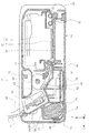
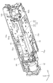
図1は本発明に係るプリンター(以下、プリンター10という。)の外観斜視図であり、図2はプリンター10を下方側から見た斜視図であり、図3はプリンター10における媒体搬送経路を示す側断面図であり、図4はプリンター10の装置本体を下方側から見た斜視図であり、図5は図4における装置本体において基板のシールド板及びバッテリーカバーを取り外した状態を示す斜視図である。
1 is an external perspective view of a printer according to the present invention (hereinafter referred to as a printer 10), FIG. 2 is a perspective view of the
図6は媒体支持部におけるバッテリー収容部と第1の基板及び第2の基板との位置関係を示す斜視図であり、図7は装置本体の背面における第1の基板とバッテリーとの位置関係を示す平面図であり、図8は装置本体の下面における第2の基板とバッテリーとの位置関係を示す平面図であり、図9は媒体支持部材を上方側から見た外観斜視図であり、図10は媒体支持部材にバッテリーを装着した状態を示す媒体支持部材の斜視図である。 FIG. 6 is a perspective view showing the positional relationship between the battery accommodating portion and the first substrate and the second substrate in the medium support portion, and FIG. 7 shows the positional relationship between the first substrate and the battery on the back surface of the apparatus main body. 8 is a plan view showing the positional relationship between the second substrate and the battery on the lower surface of the apparatus main body, and FIG. 9 is an external perspective view of the medium support member as viewed from above. 10 is a perspective view of the medium support member showing a state in which a battery is mounted on the medium support member.
図11は媒体支持部材にバッテリーを装着した状態を示す媒体支持部材の側断面図であり、図12は図10における媒体支持部材からバッテリーカバーを取り外した状態を示す媒体支持部材の斜視図であり、図13(A)はバッテリーの外観斜視図であり、図13(B)はバッテリーカバーの外観斜視図であり、図14は媒体支持部材において媒体戻しレバーが設けられた部分における断面図である。 11 is a side sectional view of the medium support member showing a state where a battery is mounted on the medium support member, and FIG. 12 is a perspective view of the medium support member showing a state where the battery cover is removed from the medium support member in FIG. 13A is an external perspective view of the battery, FIG. 13B is an external perspective view of the battery cover, and FIG. 14 is a cross-sectional view of the medium support member where the medium return lever is provided. .
各図において示すX−Y−Z座標系はX方向が記録ヘッドの走査方向および装置幅方向、Y方向が記録装置の奥行き方向及び用紙搬送方向、Z方向が装置高さ方向および後述する装置本体、増設ユニット、支持台、のこれらの重畳方向を示している。尚、各図において−Y方向を装置前面側とし、+Y方向側を装置背面側とする。 In the XYZ coordinate system shown in each figure, the X direction is the scanning direction of the recording head and the apparatus width direction, the Y direction is the depth direction of the recording apparatus and the paper transport direction, the Z direction is the apparatus height direction, and the apparatus main body described later. The overlapping directions of the extension unit and the support base are shown. In each figure, the -Y direction is the front side of the apparatus, and the + Y direction side is the back side of the apparatus.
■■■プリンターの概要について■■■■
図1ないし図3を参照して記録装置の一例としてのインクジェットプリンター10(以下、プリンター10という)について説明する。プリンター10は、装置本体12(図4参照)と、装置本体12の外観を構成するハウジング14と、装置本体12に対して開閉可能なカバー16とを備えている。
■■■ About the printer overview ■■■■
An ink jet printer 10 (hereinafter referred to as a printer 10) as an example of a recording apparatus will be described with reference to FIGS. The
カバー16は、装置本体12に対して回動可能に取り付けられており、図1に示すような閉じた状態と、図3に示すように装置本体12に対して回動させて開いた状態とを取り得る。尚、図3において説明のためカバー16は一部のみ図示している。また、カバー16は、図1に示すように閉じた状態においてプリンター10の上面及び前面の一部を構成する。
The
また、図2に示すようにプリンター10のハウジング14の背面には複数の弾性部材18が設けられている。この弾性部材18は、プリンター10の背面側を底部として机やテーブル等に置く際の支持部として機能する。
As shown in FIG. 2, a plurality of
次いで、図3を参照しながらプリンター10における媒体搬送経路上の構成要素についてさらに詳説する。図3において紙面右側(装置背面側)が給送経路上流であり、紙面左側(装置前面側)が給送経路下流となっている。また、図3における符号20が付された一点鎖線は、媒体の搬送経路を示している。尚、本明細書における媒体とは、普通紙や写真、はがき等の用紙を指している。
Next, components on the medium conveyance path in the
給送経路上流側には、ハウジング14に対してカバー16が開かれた状態において媒体を供給可能な媒体供給部22が設けられている。媒体供給部22には、媒体を傾斜姿勢で支持する媒体支持部24と、媒体支持部24に支持された媒体を媒体搬送経路下流側に搬送する、「媒体給送手段」としての給送ローラー26と、媒体戻しレバー28とを備えている。
A
媒体支持部24は、図3において−Y方向側に向かって下がり傾斜状に形成されている。また、媒体支持部24は、支持部材30を備えている(図9参照)。支持部材30は、給送ローラー26に対して接離方向に揺動可能に構成されている。
The
給送ローラー26は、支持部材30が給送ローラー26に接近する方向に変位した際、支持部材30に載置された最上位の媒体と接し、該最上位の媒体を給送経路下流側に給送する。この際、次位以降の媒体は、媒体戻しレバー28により支持部材30に戻され、次位以降の媒体が不用意に給送経路下流側に給送されることを防止する。尚、給送ローラー26は装置本体12内に設けられた、「第1のモーター」としての給送ローラー駆動モーター32(図4及び図5参照)により回転駆動させられる。
When the
媒体供給部22の下流側には搬送部34が設けられている。搬送部34には、一対の搬送ローラー対36が設けられている。搬送ローラー対36は複数の歯車を介して「第2のモーター」としての駆動モーター38(図4及び図5参照)により回転駆動させられる。搬送部34は、媒体供給部22から給送された媒体を搬送ローラー対36でニップして搬送方向下流側に搬送する。搬送部34の下流側には記録部40が設けられている。
A
記録部40は、キャリッジ42と、該キャリッジの底部に設けられた記録ヘッド44と、該記録ヘッドに対向し、媒体を支持するプラテン46とを備えている。記録ヘッド44は、プラテン46に支持された媒体と対向する。キャリッジ42は、装置本体12内部に設けられたキャリッジ駆動モーター48(図4及び図5参照)によって図3におけるX軸方向(紙面表裏方向)に往復動する様に駆動される。また、プラテン46は、媒体を下方から支持することにより、媒体の記録面と記録ヘッド44のヘッド面との間の距離(ギャップ)を規定する。
The
記録部40では、プラテン46に支持された媒体が記録ヘッド44に対向した際、記録ヘッド44の複数のノズル穴(図示せず)から「液体」としてのインクが媒体に向けて吐出され、当該インクが媒体の記録面(記録ヘッド44に対向する面)に着弾することにより記録が実行される。
In the
記録部40の搬送方向下流側には、排出部50が設けられている。排出部50は、排出ローラー対52を備えている。記録部40で記録が実行された媒体は、排出ローラー対52にニップされて装置前面から装置前方に向けて排出される。尚、排出ローラー対52は複数の歯車を介して駆動モーター38(図4及び図5参照)により回転駆動させられる。
A
尚、本実施例において、給送ローラー26を回転駆動させる給送ローラー駆動モーター32、搬送ローラー対36及び排出ローラー対52を回転駆動させる駆動モーター38及びキャリッジ42をX軸方向に移動させるキャリッジ駆動モーター48は後述する、「制御手段」としての制御部54(図5及び図6参照)により制御されている。
In this embodiment, the feed
■■■実施例について■■■■
■■■装置本体12の構成について■■■■
次いで、図4ないし図8を参照して装置本体12の構成、具体的には媒体支持部24、給送ローラー駆動モーター32、駆動モーター38、制御部54、後述するバッテリー収容部56について説明する。装置本体12の背面側、つまり+Y軸方向側の端部には、媒体支持部24が配置されている。
■■■ About Examples ■■■■
■■■ About the configuration of the
Next, the configuration of the apparatus
図6を参照するに媒体支持部24には、装置高さ方向における下側つまり−Z軸方向側にバッテリー収容部56が設けられている。また、バッテリー収容部56は、媒体支持部24の幅方向であるX軸方向において中央部に設けられている。また、バッテリー収容部56は、媒体支持部24において装置奥行き方向であるY軸方向における+Y軸方向側の端部に設けられている。
Referring to FIG. 6, the
ここで、図4及び図5を参照するに、装置本体12の背面側、つまり媒体支持部24の+Y軸方向側の端部には、給送ローラー駆動モーター32及び駆動モーター38が設けられている。本実施例では、給送ローラー駆動モーター32は、装置本体12(媒体支持部24)の−X軸方向側の端部に設けられており、駆動モーター38は装置本体12(媒体支持部24)の+X軸方向側の端部に設けられている。尚、図6において媒体支持部24の+X軸方向側の端部における駆動モーター38の図示は省略されている。
4 and 5, a feed
すなわち、バッテリー収容部56は、媒体支持部24においてX軸方向における給送ローラー駆動モーター32と駆動モーター38との間に設けられている(図4ないし図6参照)。
That is, the
つまり、本実施例では装置本体12における媒体の給送方向であるY軸方向と交差する媒体幅方向であるX軸方向においてバッテリー収容部56の両側にそれぞれ給送ローラー駆動モーター32及び駆動モーター38が設けられている。したがって、プリンター10における重量物が一箇所に偏らず、プリンター10の持ち運び性が向上する。
That is, in this embodiment, the feeding
また、図4及び図5を参照するに、装置本体12の底部において装置前方側には、「第1液体保持部」としてのインク吸収体55と、「第2液体保持部」としての廃インクカートリッジ57とが設けられている。インク吸収体55及び廃インクカートリッジ57は、それぞれプラテン46の下方に設けられている。また、インク吸収体55及び廃インクカートリッジ57は、プラテン46の下方において媒体の搬送方向に対して並列に配置されている。
4 and 5, an
インク吸収体55は、記録部40において媒体へ縁無し記録を実行する際、媒体の端部から外れた領域に吐出されて、プラテン46の上方から下方に導かれたインクを保持するように構成されている。具体的には、インク吸収体55は、スポンジ材で構成されている。
The
また、装置本体12内においてキャリッジ42の移動領域の−X軸方向側の端部にはキャップ手段61(図4及び図5参照)が設けられている。キャップ手段61は、ポンプ63に接続されている。キャップ手段61は、記録ヘッド44が当該キャップ手段61に対向する位置にある際、記録ヘッド44と係合し、ポンプ63により記録ヘッド44のノズル内のインクを吸引し、あるいは記録ヘッド44からフラッシング動作により打ち捨てられたインクを受ける。
Further, cap means 61 (see FIGS. 4 and 5) is provided at the end of the moving area of the
廃インクカートリッジ57は、ポンプ63を介してキャップ手段61に接続されている。廃インクカートリッジ57は、キャップ手段61に打ち捨てられた廃インクあるいは、ポンプ63により吸引された廃インクであってポンプ63から送出された廃インクを、カートリッジ内に収容する。
The
制御部54は、複数の基板から構成されている。本実施例では、制御部54は第1の基板58と第2の基板60とを備えている(図5参照)。図5及び図6に示すように第1の基板58及び第2の基板60は媒体支持部24において当該媒体支持部24の下側に配置されるとともにバッテリー収容部56に近接して配置されている。尚、各基板には、複数の電気抵抗やコンデンサー等が配置され、電気回路が形成されている。
The
図5に示すように第1の基板58は、装置本体12の背面側、つまり+Y軸方向側の端部においてZ軸方向に沿って立設姿勢に設けられ、媒体支持部24を形成するフレーム66の一部に固定されている(図6参照)。また、第2の基板60は、第1の基板58と交差する姿勢を成している(図5参照)。具体的には第2の基板60は、装置本体12の底部に設けられ、Z軸方向と交差するXY平面に平行に設けられている(図8参照)。
As shown in FIG. 5, the
また、図4に示すように第1の基板58にはシールド板62が取り付けられている。また、第2の基板60においてもシールド板64が取り付けられている。本実施例においてシールド板62、64は導電材料で形成されており、第1の基板58及び第2の基板60に対するノイズの影響を低減する。
Further, as shown in FIG. 4, a
図7に示すように、第1の基板58において−X軸方向側の端部には「第1の切り欠き部」としての切り欠き部58aが形成されている。装置本体12の背面側において、バッテリー収容部56はX軸方向においてその一部が第1の基板58の切り欠き部58aに入り込んだ状態で配置されている。
As shown in FIG. 7, a
また、装置本体12における装置高さ方向であるZ軸方向において装置本体12に対するバッテリー収容部56の配置領域は、第1の基板58及び第2の基板60の配置領域と少なくとも一部が同じ範囲内にある。したがって、バッテリー収容部56と、各基板58、60を装置高さ方向(Z軸方向)に積み重ねて配置する必要がないことから、プリンター10の装置高さ方向(Z軸方向)の寸法を小さくすること、又は抑えることができる。
In addition, the arrangement region of the
また、図8に示すように、第2の基板60において−X軸方向側の端部には「第1の切り欠き部」としての切り欠き部60aが形成されている。装置本体12の底部において、バッテリー収容部56はX軸方向においてその一部が第2の基板60の切り欠き部60aに入り込んだ状態で配置されている。
Further, as shown in FIG. 8, a
また、図5に示すように、第2の基板60は装置本体12の底部に設けられており、インク吸収体55及び廃インクカートリッジ57も装置本体12の底部に設けられている。
すなわち、装置高さ方向において第2の基板60の占有領域は、インク吸収体55の占有領域および廃インクカートリッジ57の占有領域と重なっている。
したがって、インク吸収体55及び廃インクカートリッジ57を備えた構成において装置の小型化を図ることができる。
As shown in FIG. 5, the
That is, the occupied area of the
Therefore, the apparatus can be miniaturized in the configuration including the
また、装置本体12における装置奥行き方向であるY軸方向において装置本体12に対するバッテリー収容部56の配置領域は、第1の基板58及び第2の基板60の配置領域と少なくとも一部が同じ範囲内にある。したがって、バッテリー収容部56と、各基板58、60を装置奥行き方向(Y軸方向)に重ねて配置する必要がないことから、プリンター10の装置奥行き方向(Y軸方向)の寸法を小さくすること、又は抑えることができる。
Further, in the Y axis direction that is the apparatus depth direction in the apparatus
さらに、本実施例においてバッテリー収容部56は、少なくとも一部が第1の基板58に形成された第2の切り欠き部58bに入り込むとともに、第2の基板60に形成された第2の切り欠き部60bに入り込んでいる。
したがって、このように構成することにより、装置の小型化を図ることができる。
Further, in the present embodiment, the
Therefore, with this configuration, the apparatus can be reduced in size.
また、図5ないし図7を参照するに、第1の基板58において+X軸方向側の端部には「第2の切り欠き部」としての切り欠き部58bが形成されている。さらに、図5、図6及び図8を参照するに第2の基板60において+X軸方向側の端部には「第2の切り欠き部」としての切り欠き部60bが形成されている。本実施例において、図5に示すように駆動モーター38は、装置本体12(媒体支持部24)の+X軸方向側の端部において第1の基板58の切り欠き部58b及び第2の基板60の切り欠き部60bに対応する位置に配置されている。
5 to 7, a
つまり、本実施例では、駆動モーター38は、第1の基板58に形成された第2の切り欠き部58bに入り込むとともに、第2の基板60に形成された第2の切り欠き部60bに入り込んでいる。
したがって、このように構成することにより、装置の小型化を図ることができる。
That is, in this embodiment, the
Therefore, with this configuration, the apparatus can be reduced in size.
ここで、バッテリー収容部56と第1の基板58及び第2の基板60の位置関係をまとめる。第1の基板58及び第2の基板60には複数の電子部品が取り付けられ、電気回路が形成されている。これらの電子部品から発した熱は、第1の基板58及び第2の基板60において電子部品が取り付けられた基板面から放熱され、基板面に面する領域に放出される。バッテリー収容部56は図7におけるX軸方向において第1の基板58の側方に位置するので、第1の基板58の基板面に面していない。したがって、バッテリー収容部56は装置本体12内において第1の基板58からの放熱を直接受け難い配置となっている。
Here, the positional relationship between the
さらに、バッテリー収容部56は図8におけるX軸方向において第2の基板60の側方に位置するので、第2の基板60の基板面に面していない。したがって、バッテリー収容部56は装置本体12内において第2の基板60からの放熱を直接受け難い配置となっている。
Further, since the
上記説明をまとめると、バッテリー収容部56、第1の基板58及び第2の基板60は、媒体支持部24の下側に配置されるとともに、第1の基板58及び第2の基板60に面する場所から外れた位置にバッテリー収容部56が配置されている為、バッテリー74(図13(A)参照)が第1の基板58及び第2の基板60からの放熱を直接受け難く、バッテリー74を良好な状態に保つことができる。
In summary, the
■■■媒体支持部及びバッテリー収納部の構成について■■■■
さらに図9ないし図13を参照して、媒体支持部24及びバッテリー収容部56の構成について説明する。図9に示すように媒体支持部24はフレーム66を備えている。フレーム66の上部には、支持部材30が取り付けられている。支持部材30は、支持部材30の上端に設けられた一対の揺動軸68を中心としてフレーム66に対して揺動可能に構成されている。
■■■ About the structure of the media support and battery compartment ■■■■
Further, with reference to FIGS. 9 to 13, configurations of the
また、フレーム66には支持部材30と対向する位置にX軸方向に延びる給送ローラー駆動軸70がフレーム66に対して回転可能に取り付けられている。給送ローラー駆動軸70には、給送ローラー26が当該給送ローラー駆動軸70と一体に回転可能に取り付けられている。
A feed
また、フレーム66において媒体搬送経路における支持部材30の下流側には、X軸方向に適宜間隔をおいて複数の開口72が設けられている。各開口72には、媒体戻しレバー28が設けられている。媒体戻しレバー28は給送ローラー駆動モーター32から駆動力を受ける駆動機構(不図示)により、媒体搬送経路に進出し、あるいは退避するように揺動駆動される。そして、媒体戻しレバー28が媒体搬送経路に進出する際、媒体戻しレバー28の少なくとも一部が開口72より媒体搬送経路側に突出し、開口72から露出する。
Further, on the downstream side of the
図10ないし図12に示すように、フレーム66の下部には、バッテリー収容部56が設けられている。より具体的には、図11に示すようにフレーム66は、−Y方向側に向かって下がり傾斜状に形成され、傾斜面には支持部材30が設けられている(図3参照)。尚、図11において支持部材30は、図示を省略している。
As shown in FIGS. 10 to 12, a
媒体支持部24は用紙を傾斜姿勢に支持する為、その下側には空間(デッドスペース)が形成される。バッテリー収容部56はこの空間を利用して配置される。より詳しくは、前記空間においてフレーム66のX軸方向における中央部には、バッテリー収容部56がフレーム66に一体的に形成されている。つまり、バッテリー収容部56は、媒体支持部24を形成するフレーム66に一体的に形成されているのでプリンター10の低コスト化を図ることができる。
Since the
バッテリー収容部56は、図10ないし図12に示すように箱状に形成され、−Z軸方向に開口している。バッテリー収容部56内には、着脱可能にバッテリー74が取り付けられている。バッテリー収容部56の−Z軸方向の開口には、図10に示すようにバッテリー収容部カバー76が着脱可能に取り付けられている。
The
バッテリー74は、図13(A)に示すようにX軸方向に延びる形態を成している。そして、バッテリー74のX軸方向の両端部には、図13(A)では図示していないがそれぞれ端子が設けられている。これら両端子と、制御部54の各基板58、60、給送ローラー駆動モーター32、駆動モーター38及びキャリッジ駆動モーター48とは電気的に接続され、これらの部材を駆動するための電力を供給する。
The
また、バッテリー収容部カバー76は、図13(B)に示すように箱状に形成され、+Z軸方向側が開口している。バッテリー収容部カバー76は、図示しないネジ等の締結部材によりバッテリー収容部56に取り付けられる。さらに、バッテリー収容部56にバッテリー74を収容して当該バッテリー収容部56にバッテリー収容部カバー76を取り付ける際、バッテリー74とバッテリー収容部カバー76との間には、弾性部材78(図11参照)が取り付けられている。
Further, the battery
本実施例において、弾性部材78はスポンジ材で構成されている。弾性部材78は、バッテリー収容部56にバッテリー74を収容して当該バッテリー収容部56にバッテリー収容部カバー76を取り付けた際、その弾性力によりバッテリー74をバッテリー収容部56内において+Z軸方向に付勢し、当該バッテリー収容部56内における所定の位置に保持する。
In this embodiment, the
また、バッテリー収容部カバー76の+Y軸方向側の端部には、+Z軸方向側に突出する複数の係合部76aが設けられている。係合部76aは、バッテリー収容部カバー76をバッテリー収容部56に取り付けた際、当該バッテリー収容部56の+Y軸方向側の端部に複数設けられたフック56aとそれぞれ係合する。
Further, a plurality of engaging
また、図11に示すようにバッテリー収容部56にバッテリー収容部カバー76を取り付けた際、係合部76aとバッテリー収容部56の+Y軸方向側の端部との間には弾性部材80が配置されている。弾性部材80もスポンジ材で構成されている。弾性部材80は、図11におけるY軸方向においてバッテリー収容部カバー76がバッテリー収容部56に対してずれることを抑制する。
As shown in FIG. 11, when the battery
■■■媒体支持部及び第2の基板との関係について■■■■
次に図6、図9、図12及び図14を参照して、媒体支持部24におけるフレーム66と第2の基板60との関係について説明する。先に説明したようにフレーム66には、媒体戻しレバー28を収容する開口72(図9参照)が複数設けられている。フレーム66において開口72の−Z軸方向側には空間82(図14参照)が形成されている。空間82は、図14に示すように媒体戻しレバー28の少なくとも一部を収容する。
■■■ Relationship with media support and second substrate ■■■■
Next, the relationship between the
また、図14に示すように、フレーム66の下部には第2の基板60が配置されている。第2の基板60は、フレーム66の下部においてXY平面に沿って延びている。そして、第2の基板60の少なくとも一部は、空間82に面している。
Further, as shown in FIG. 14, a
ここで、第2の基板60と空間82の−Z軸方向側の端部との間には、放熱部材84が設けられている。つまり、放熱部材84は第2の基板60に対し開口72に面する位置に設けられている。放熱部材84は、一例として熱伝導率の高い材質で構成されている。
Here, a
ここで第2の基板60には、複数の電気抵抗やコンデンサー等が設けられており、制御部54に通電するとこれらの部材が発熱する。第2の基板60から放たれた熱は、放熱部材84を介して空間82へと伝えられ、空間82から開口72を経て放出される。
Here, the
つまり、本実施例では媒体支持部24を形成するフレーム66に形成された、媒体戻しレバー28を露出させる開口72が、第2の基板60から生じた熱を放出する放熱口を兼ねるので、第2の基板60から生じた熱を放出する放熱口を別途設ける必要がなく、装置のコストアップを抑えることができるとともに、第2の基板60から生じた熱を良好に放出できる。
In other words, in this embodiment, the
また、本実施例では、放熱部材84は空間82と第2の基板60とを仕切っているので、開口72から空間82内に侵入した塵埃等が第2の基板60に付着することを防止できる。その結果、第2の基板60の性能を良好に維持することができる。
In this embodiment, since the
<<<実施例の変更例>>>
(1)本実施例では、開口72から第2の基板60における熱を放熱する構成としたが、この構成に代えて第1の基板58から開口72を介して放熱する構成としてもよく、又は開口72から第1の基板58及び第2の基板60の両方の熱を放熱する構成としてもよい。
また、媒体戻しレバー28にフラップ部材を取付けて媒体戻しレバーの作動時に空間82の空気を攪拌し、開口72からの放熱を促す構成としてもよい。
(2)本実施例において、第1の基板58の切り欠き部58bと第2の基板60の切り欠き部60bに対応する位置には駆動モーター38を配置する構成としたが、この構成に代えて、第1の基板58の切り欠き部58bと第2の基板60の切り欠き部60bに対応する位置には給送ローラー駆動モーター32を配置する構成としてもよい。
<<< Example of change of embodiment >>>
(1) In the present embodiment, the heat in the
Alternatively, a flap member may be attached to the
(2) In the present embodiment, the
上記説明をまとめると、本実施例におけるプリンター10は、媒体を傾斜状態に支持する媒体支持部24と、媒体支持部24に支持された媒体を送り出す給送ローラー26と、装置の制御部54を構成する基板58、60と、給送ローラー26及び制御部54の動力源であるバッテリー74を収容するバッテリー収容部56とを備えている。
バッテリー収容部56及び基板58、60は、媒体支持部24の下側に配置されるとともに、基板58、60に面する場所から外れた位置にバッテリー収容部56が配置されている。バッテリー収容部56の配置領域と基板58、60の配置領域は、高さ方向で少なくとも一部が同じ範囲にある。
In summary, the
The
また、バッテリー収容部56の配置領域と基板58、60の配置領域は、装置奥行き方向で少なくとも一部が同じ範囲にある。
In addition, the arrangement area of the
バッテリー収容部56は、少なくとも一部が基板58、60に形成された切り欠き部58a、60aに入り込んでいる。また、バッテリー収容部56は、媒体の給送方向であるY軸方向と交差する方向である媒体幅方向つまりX軸方向において中央部に設けられている。バッテリー収容部56は、媒体支持部24の下側に形成された空間において、装置奥行き方向であるY軸方向の後方側つまり+Y軸方向側に設けられている。
The
プリンター10は、基板58、60を複数備えている。複数の基板を構成する第1の基板58は、装置奥行き方向の後方側つまり+Y軸方向側において立設姿勢に設けられ、複数の前記基板を構成する第2の基板60は、第1の基板58と交差する姿勢を成している。
The
プリンター10は、バッテリー74により駆動される給送ローラー駆動モーター32及び駆動モーター38を備えている。給送ローラー駆動モーター32及び駆動モーター38が、媒体の給送方向であるY軸方向と交差する方向である媒体幅方向すなわちX軸方向においてバッテリー収容部56の両側に設けられている。
The
給送ローラー駆動モーター32及び駆動モーター38の少なくとも一方は、第1の基板58に形成された第2の切り欠き部58bに入り込むとともに、第2の基板60に形成された第2の切り欠き部60bに入り込んでいる。
At least one of the feed
プリンター10は、媒体支持部24から送り出された媒体の先端を媒体支持部24の側へ戻す媒体戻しレバー28と、媒体支持部24を形成するフレーム66に形成された、媒体戻しレバー28を露出させる開口72とを備えている。開口72は、第2の基板60から生じた熱を放出する放熱口を兼ねている。
The
バッテリー収容部56は、媒体支持部24を形成するフレーム66に一体的に形成されている。第2の基板60から生じた熱は、第2の基板60に対し開口72に面する位置に設けられた放熱部材84を介して開口72から放出される。
The
プリンター10は、媒体に対し液体を噴射する記録ヘッド44と、記録ヘッド44と対向可能な位置に設けられた、媒体を支持するプラテン46と、媒体の端部から外れた領域に噴射され、プラテン46の上方から下方に導かれたインクを保持するインク吸収体55と、記録ヘッド44から廃液として噴射されたインクを保持する廃インクカートリッジ57とを備えている。第2の基板60の占有領域は、インク吸収体55の占有領域および廃インクカートリッジ57の占有領域と、装置高さ方向で重なっている。
The
また、本実施形態では本発明に係るバッテリー収容部56を記録装置の一例としてのインクジェットプリンターに適用したが、その他液体噴射装置一般に適用することも可能である。
ここで、液体噴射装置とは、インクジェット式記録ヘッドが用いられ、該記録ヘッドからインクを吐出して被記録媒体に記録を行うプリンター、複写機及びファクシミリ等の記録装置に限らず、インクに代えてその用途に対応する液体を前記インクジェット式記録ヘッドに相当する液体噴射ヘッドから被記録媒体に相当する被噴射媒体に噴射して、前記液体を前記被噴射媒体に付着させる装置を含むものである。
Further, in the present embodiment, the
Here, the liquid ejecting apparatus uses an ink jet recording head, and is not limited to a recording apparatus such as a printer, a copier, and a facsimile machine that discharges ink from the recording head to perform recording on a recording medium. And a device for ejecting a liquid corresponding to the application from a liquid ejecting head corresponding to the ink jet recording head to an ejected medium corresponding to the recording medium, and attaching the liquid to the ejected medium.
液体噴射ヘッドとして、前記記録ヘッドの他に、液晶ディスプレー等のカラーフィルター製造に用いられる色材噴射ヘッド、有機ELディスプレーや面発光ディスプレー(FED)等の電極形成に用いられる電極材(導電ペースト)噴射ヘッド、バイオチップ製造に用いられる生体有機物噴射ヘッド、精密ピペットとしての試料噴射ヘッド等が挙げられる。 In addition to the recording head, as a liquid ejecting head, a color material ejecting head used for manufacturing a color filter such as a liquid crystal display, and an electrode material (conductive paste) used for forming an electrode such as an organic EL display or a surface emitting display (FED) Examples thereof include an ejection head, a bioorganic matter ejection head used for biochip production, and a sample ejection head as a precision pipette.
尚、本発明は上記実施例に限定されることなく、特許請求の範囲に記載した発明の範囲内で、種々の変形が可能であり、それらも本発明の範囲内に含まれるものであることは言うまでもない。 The present invention is not limited to the above-described embodiments, and various modifications can be made within the scope of the invention described in the claims, and these are also included in the scope of the present invention. Needless to say.
10 プリンター、12 装置本体、14 ハウジング、16 カバー、18 弾性部材、
22 媒体供給部、24 媒体支持部、26 給送ローラー、28 媒体戻しレバー、
30 支持部材、32 給送ローラー駆動モーター、34 搬送部、
36 搬送ローラー対、38 駆動モーター、40 記録部、42 キャリッジ、
44 記録ヘッド、46 プラテン、48 キャリッジ駆動モーター、50 排出部、
52 排出ローラー対、54 制御部、55 インク吸収体、56 バッテリー収容部、56a フック、57 廃インクカートリッジ、58 第1の基板、
58a、58b、60a、60b 切り欠き部、60 第2の基板、61 キャップ手段、
62、64 シールド板、63 ポンプ、66 フレーム、68 揺動軸、
70 給送ローラー駆動軸、72 開口、74 バッテリー、
76 バッテリー収容部カバー、76a 係合部、78、80 弾性部材、82 空間、84 放熱部材
10 printer, 12 device main body, 14 housing, 16 cover, 18 elastic member,
22 Medium supply unit, 24 Medium support unit, 26 Feed roller, 28 Medium return lever,
30 support members, 32 feed roller drive motors, 34 transport units,
36 transport roller pairs, 38 drive motors, 40 recording units, 42 carriages,
44 recording head, 46 platen, 48 carriage drive motor, 50 discharge section,
52 discharge roller pair, 54 control unit, 55 ink absorber, 56 battery housing unit, 56a hook, 57 waste ink cartridge, 58 first substrate,
58a, 58b, 60a, 60b notch, 60 second substrate, 61 cap means,
62, 64 Shield plate, 63 Pump, 66 Frame, 68 Oscillating shaft,
70 Feed roller drive shaft, 72 opening, 74 battery,
76 battery housing part cover, 76a engaging part, 78, 80 elastic member, 82 space, 84 heat dissipation member
Claims (14)
前記媒体支持部に支持された媒体を送り出す媒体給送手段と、
装置の制御手段を構成する基板と、
前記媒体給送手段及び前記制御手段の動力源であるバッテリーを収容するバッテリー収容部と、を備え、
前記バッテリー収容部及び前記基板は、それぞれ少なくとも一部が、装置高さ方向において前記支持部材の下側、かつ装置奥行き方向において前記支持部材の領域内に配置されるとともに、前記基板に面する場所から外れた位置に前記バッテリー収容部が配置され、
前記バッテリー収容部の配置領域と前記基板の配置領域は、高さ方向で少なくとも一部が同じ範囲にあり、
前記バッテリー収容部は、少なくとも一部が前記基板に形成された第1の切り欠き部に入り込んでいる、
ことを特徴とする記録装置。 A medium support portion having a support member formed in an inclined manner in a medium conveying direction and supporting the medium in an inclined state;
Medium feeding means for feeding out the medium supported by the medium support section;
A substrate constituting the control means of the apparatus;
A battery accommodating portion for accommodating a battery that is a power source of the medium feeding means and the control means,
The battery accommodating portion and the substrate are each disposed at least partially below the support member in the device height direction and in the region of the support member in the device depth direction, and facing the substrate The battery accommodating portion is disposed at a position deviated from,
The arrangement region of the battery housing part and the arrangement region of the substrate are at least partially in the same range in the height direction,
The battery housing portion is at least partially inserted into a first cutout portion formed in the substrate;
A recording apparatus.
ことを特徴とする記録装置。 The recording apparatus according to claim 1, wherein at least a part of the arrangement area of the battery housing portion and the arrangement area of the substrate are in the same range in the apparatus depth direction.
A recording apparatus.
ことを特徴とする記録装置。 3. The recording apparatus according to claim 1, wherein the battery housing portion is provided at a central portion in a medium width direction that is a direction intersecting a medium feeding direction.
A recording apparatus.
ことを特徴とする記録装置。 4. The recording apparatus according to claim 1, wherein the battery housing portion is provided on a rear side in a device depth direction in a space formed below the medium support portion. ,
A recording apparatus.
前記媒体支持部に支持された媒体を送り出す媒体給送手段と、
装置の制御手段を構成する複数の基板と、
前記媒体給送手段及び前記制御手段の動力源であるバッテリーを収容するバッテリー収容部と、を備え、
前記バッテリー収容部及び前記基板は、前記媒体支持部の下側に配置されるとともに、前記基板に面する場所から外れた位置に前記バッテリー収容部が配置され、
前記バッテリー収容部の配置領域と前記基板の配置領域は、高さ方向で少なくとも一部が同じ範囲にあり、
前記バッテリー収容部は、少なくとも一部が前記基板に形成された第1の切り欠き部に入り込み、
複数の前記基板を構成する第1の基板は、装置奥行き方向の後方側において立設姿勢に設けられ、
複数の前記基板を構成する第2の基板は、前記第1の基板と交差する姿勢を成す、
ことを特徴とする記録装置。 A medium support part for supporting the medium in an inclined state;
Medium feeding means for feeding out the medium supported by the medium support section;
A plurality of substrates constituting the control means of the apparatus;
A battery accommodating portion for accommodating a battery that is a power source of the medium feeding means and the control means,
The battery housing portion and the substrate are disposed below the medium support portion, and the battery housing portion is disposed at a position away from a location facing the substrate,
The arrangement region of the battery housing part and the arrangement region of the substrate are at least partially in the same range in the height direction,
The battery housing portion, viewed write enters the first notch portion formed at least in part on said substrate,
The first substrate constituting the plurality of substrates is provided in a standing posture on the rear side in the apparatus depth direction,
A plurality of second substrates constituting the plurality of substrates are configured to intersect with the first substrate;
A recording apparatus.
複数の前記基板を構成する第1の基板は、装置奥行き方向の後方側において立設姿勢に設けられ、
複数の前記基板を構成する第2の基板は、前記第1の基板と交差する姿勢を成す、
ことを特徴とする記録装置。 The recording apparatus according to any one of claims 1 to 4, comprising a plurality of the substrates,
The first substrate constituting the plurality of substrates is provided in a standing posture on the rear side in the apparatus depth direction,
A plurality of second substrates constituting the plurality of substrates are configured to intersect with the first substrate;
A recording apparatus.
前記媒体支持部に支持された媒体を送り出す媒体給送手段と、
装置の制御手段を構成する基板と、
前記媒体給送手段及び前記制御手段の動力源であるバッテリーを収容するバッテリー収容部と、
前記バッテリーにより駆動される第1のモーター及び第2のモーターと、
を備え、
前記バッテリー収容部及び前記基板は、前記媒体支持部の下側に配置されるとともに、前記基板に面する場所から外れた位置に前記バッテリー収容部が配置され、
前記バッテリー収容部の配置領域と前記基板の配置領域は、高さ方向で少なくとも一部が同じ範囲にあり、
前記バッテリー収容部は、少なくとも一部が前記基板に形成された第1の切り欠き部に入り込み、
前記第1のモーター及び前記第2のモーターが、媒体の給送方向と交差する方向である媒体幅方向において前記バッテリー収容部の両側に設けられている、
ことを特徴とする記録装置。 A medium support part for supporting the medium in an inclined state;
Medium feeding means for feeding out the medium supported by the medium support section;
A substrate constituting the control means of the apparatus;
A battery accommodating portion for accommodating a battery as a power source of the medium feeding means and the control means;
A first motor and a second motor driven by the battery;
With
The battery housing portion and the substrate are disposed below the medium support portion, and the battery housing portion is disposed at a position away from a location facing the substrate,
The arrangement region of the battery housing part and the arrangement region of the substrate are at least partially in the same range in the height direction,
The battery housing portion, viewed write enters the first notch portion formed at least in part on said substrate,
The first motor and the second motor are provided on both sides of the battery housing portion in a medium width direction that is a direction intersecting a medium feeding direction.
A recording apparatus.
前記第1のモーター及び前記第2のモーターが、媒体の給送方向と交差する方向である媒体幅方向において前記バッテリー収容部の両側に設けられている、
ことを特徴とする記録装置。 The recording apparatus according to any one of claims 1 to 6 , comprising a first motor and a second motor driven by the battery,
The first motor and the second motor are provided on both sides of the battery housing portion in a medium width direction that is a direction intersecting a medium feeding direction.
A recording apparatus.
ことを特徴とする記録装置。 The recording apparatus according to claim 7 or 8 , wherein at least one of the first motor and the second motor enters a second notch formed in the substrate.
A recording apparatus.
前記媒体支持部に支持された媒体を送り出す媒体給送手段と、
装置の制御手段を構成する基板と、
前記媒体給送手段及び前記制御手段の動力源であるバッテリーを収容するバッテリー収容部と、
前記媒体支持部から送り出された媒体の先端を前記媒体支持部の側へ戻す媒体戻し部材と、
前記媒体支持部を形成するフレームに形成された、前記媒体戻し部材を露出させる開口と、
を備え、
前記バッテリー収容部及び前記基板は、前記媒体支持部の下側に配置されるとともに、前記基板に面する場所から外れた位置に前記バッテリー収容部が配置され、
前記バッテリー収容部の配置領域と前記基板の配置領域は、高さ方向で少なくとも一部が同じ範囲にあり、
前記バッテリー収容部は、少なくとも一部が前記基板に形成された第1の切り欠き部に入り込み、
前記開口が、前記基板から生じた熱を放出する放熱口を兼ねる、
ことを特徴とする記録装置。 A medium support part for supporting the medium in an inclined state;
Medium feeding means for feeding out the medium supported by the medium support section;
A substrate constituting the control means of the apparatus;
A battery accommodating portion for accommodating a battery as a power source of the medium feeding means and the control means;
A medium return member for returning the leading end of the medium sent out from the medium support part to the medium support part side;
An opening formed in a frame forming the medium support portion and exposing the medium return member;
With
The battery housing portion and the substrate are disposed below the medium support portion, and the battery housing portion is disposed at a position away from a location facing the substrate,
The arrangement region of the battery housing part and the arrangement region of the substrate are at least partially in the same range in the height direction,
The battery housing portion, viewed write enters the first notch portion formed at least in part on said substrate,
The opening also serves as a heat radiating port that releases heat generated from the substrate.
A recording apparatus.
前記媒体支持部を形成するフレームに形成された、前記媒体戻し部材を露出させる開口と、を備え、
前記開口が、前記基板から生じた熱を放出する放熱口を兼ねる、
ことを特徴とする記録装置。 The recording apparatus according to any one of claims 1 to 7, wherein a medium return member that returns a leading end of the medium fed from the medium support part to the medium support part side;
An opening formed in a frame forming the medium support portion and exposing the medium return member,
The opening also serves as a heat radiating port that releases heat generated from the substrate.
A recording apparatus.
ことを特徴とする記録装置。 The recording apparatus according to any one of claims 1 to 11, wherein the battery housing portion, the frame forming the medium supporting portion are integrally formed,
A recording apparatus.
ことを特徴とする記録装置。 The recording apparatus according to claim 10 or 11 , wherein heat generated from the substrate is released from the opening via a heat dissipation member provided at a position facing the opening with respect to the substrate.
A recording apparatus.
前記液体噴射ヘッドと対向可能な位置に設けられた、媒体を支持する支持部材と、
媒体の端部から外れた領域に噴射され、前記支持部材の上方から下方に導かれた液体を
保持する第1液体保持部と、
前記液体噴射ヘッドから廃液として噴射された液体を保持する第2液体保持部と、を備え、
前記第2の基板の占有領域は、前記第1液体保持部の占有領域および前記第2液体保持部の占有領域と、装置高さ方向で重なっている、
ことを特徴とする記録装置。 The recording apparatus according to claim 5 or 6 , wherein a liquid ejecting head that ejects liquid onto a medium;
A support member that is provided at a position that can face the liquid ejecting head and supports the medium;
A first liquid holding unit that holds a liquid that is sprayed to a region off the edge of the medium and guided downward from above the support member;
A second liquid holding unit that holds the liquid ejected as waste liquid from the liquid ejecting head,
The occupied area of the second substrate overlaps with the occupied area of the first liquid holding part and the occupied area of the second liquid holding part in the apparatus height direction.
A recording apparatus.
Priority Applications (2)
| Application Number | Priority Date | Filing Date | Title |
|---|---|---|---|
| JP2014062090A JP6361861B2 (en) | 2014-03-25 | 2014-03-25 | Recording device |
| US14/662,935 US9415616B2 (en) | 2014-03-25 | 2015-03-19 | Recording apparatus |
Applications Claiming Priority (1)
| Application Number | Priority Date | Filing Date | Title |
|---|---|---|---|
| JP2014062090A JP6361861B2 (en) | 2014-03-25 | 2014-03-25 | Recording device |
Publications (3)
| Publication Number | Publication Date |
|---|---|
| JP2015182369A JP2015182369A (en) | 2015-10-22 |
| JP2015182369A5 JP2015182369A5 (en) | 2017-05-18 |
| JP6361861B2 true JP6361861B2 (en) | 2018-07-25 |
Family
ID=54189151
Family Applications (1)
| Application Number | Title | Priority Date | Filing Date |
|---|---|---|---|
| JP2014062090A Active JP6361861B2 (en) | 2014-03-25 | 2014-03-25 | Recording device |
Country Status (2)
| Country | Link |
|---|---|
| US (1) | US9415616B2 (en) |
| JP (1) | JP6361861B2 (en) |
Families Citing this family (6)
| Publication number | Priority date | Publication date | Assignee | Title |
|---|---|---|---|---|
| JP2017177409A (en) * | 2016-03-29 | 2017-10-05 | 三菱電機株式会社 | Thermal Printer |
| CN110936727B (en) | 2018-09-21 | 2021-06-15 | 精工爱普生株式会社 | Mobile device |
| US11012587B2 (en) | 2018-09-21 | 2021-05-18 | Seiko Epson Corporation | Mobile device with battery |
| CN110943505B (en) | 2018-09-21 | 2023-05-05 | 精工爱普生株式会社 | Mobile device |
| JP7243220B2 (en) * | 2018-09-21 | 2023-03-22 | セイコーエプソン株式会社 | mobile device |
| JP7097000B2 (en) * | 2018-09-28 | 2022-07-07 | 株式会社リコー | Image forming apparatus and image forming apparatus main body |
Family Cites Families (14)
| Publication number | Priority date | Publication date | Assignee | Title |
|---|---|---|---|---|
| US6241407B1 (en) * | 1999-09-16 | 2001-06-05 | Monarch Marking Systems, Inc. | Portable printer |
| US6618068B2 (en) | 2000-03-14 | 2003-09-09 | Olympus Optical Co., Ltd. | Printer device |
| JP3600173B2 (en) | 2000-03-14 | 2004-12-08 | オリンパス株式会社 | Portable printer device |
| JP3805283B2 (en) * | 2002-06-10 | 2006-08-02 | アルプス電気株式会社 | Thermal printer head release detection mechanism |
| JP4387651B2 (en) | 2002-10-07 | 2009-12-16 | キヤノン株式会社 | Recording device |
| JP2004157463A (en) * | 2002-11-08 | 2004-06-03 | Brother Ind Ltd | Image forming apparatus |
| US6969168B2 (en) | 2003-09-19 | 2005-11-29 | Hewlett-Packard Development Company, L.P. | Media loading and separation system for printer |
| US7448734B2 (en) * | 2004-01-21 | 2008-11-11 | Silverbrook Research Pty Ltd | Inkjet printer cartridge with pagewidth printhead |
| JP4381402B2 (en) * | 2006-09-13 | 2009-12-09 | ティーオーエー株式会社 | Wireless microphone device |
| JP2008246691A (en) * | 2007-03-29 | 2008-10-16 | Hoya Corp | Thermal line printer and battery pack |
| US8113645B2 (en) * | 2007-11-14 | 2012-02-14 | Seiko Corporation | Recording apparatus |
| JP5146382B2 (en) * | 2009-03-25 | 2013-02-20 | 株式会社デンソー | Manufacturing method of electronic device |
| JP5733488B2 (en) * | 2009-09-25 | 2015-06-10 | セイコーエプソン株式会社 | Recording device |
| CN102738574B (en) * | 2012-06-21 | 2014-09-03 | 华为终端有限公司 | Portable terminal and slot antenna thereof |
-
2014
- 2014-03-25 JP JP2014062090A patent/JP6361861B2/en active Active
-
2015
- 2015-03-19 US US14/662,935 patent/US9415616B2/en active Active
Also Published As
| Publication number | Publication date |
|---|---|
| US9415616B2 (en) | 2016-08-16 |
| US20150273905A1 (en) | 2015-10-01 |
| JP2015182369A (en) | 2015-10-22 |
Similar Documents
| Publication | Publication Date | Title |
|---|---|---|
| JP6361861B2 (en) | Recording device | |
| JP6019835B2 (en) | Recording device | |
| JP2012061789A (en) | Recording apparatus | |
| JP5974521B2 (en) | Liquid ejector | |
| JP6388107B2 (en) | Recording device | |
| JP6738039B2 (en) | Recording device | |
| JP2006096490A (en) | Medium guide device for feeding device | |
| JP6201372B2 (en) | Recording device | |
| JP5605180B2 (en) | Recording device | |
| JP6394861B2 (en) | Recording device | |
| US20170087884A1 (en) | Printing apparatus and platen | |
| US10935918B2 (en) | Printing apparatus | |
| JP2012069587A (en) | Pair circuit board work machine and pair circuit board work system | |
| JP2008036898A (en) | Cover structure, controlling apparatus, and electronic equipment | |
| JP2012061813A (en) | Recording medium support device and recorder | |
| JP7001140B1 (en) | Processing equipment and recording equipment | |
| JP5110023B2 (en) | Liquid discharge line head and liquid discharge apparatus | |
| JP6436285B2 (en) | Recording device | |
| JP2016007763A (en) | Recording device | |
| JP6380742B2 (en) | Recording device | |
| JP5894730B2 (en) | Recording device | |
| JP5898792B2 (en) | Circuit board work system | |
| JP6056140B2 (en) | Recording device | |
| JP2023068744A (en) | Liquid jet head and liquid jet device | |
| JP2012076899A (en) | Recording apparatus |
Legal Events
| Date | Code | Title | Description |
|---|---|---|---|
| A521 | Written amendment |
Free format text: JAPANESE INTERMEDIATE CODE: A523 Effective date: 20170322 |
|
| A621 | Written request for application examination |
Free format text: JAPANESE INTERMEDIATE CODE: A621 Effective date: 20170322 |
|
| A977 | Report on retrieval |
Free format text: JAPANESE INTERMEDIATE CODE: A971007 Effective date: 20171222 |
|
| A131 | Notification of reasons for refusal |
Free format text: JAPANESE INTERMEDIATE CODE: A131 Effective date: 20180110 |
|
| A521 | Written amendment |
Free format text: JAPANESE INTERMEDIATE CODE: A523 Effective date: 20180307 |
|
| TRDD | Decision of grant or rejection written | ||
| A01 | Written decision to grant a patent or to grant a registration (utility model) |
Free format text: JAPANESE INTERMEDIATE CODE: A01 Effective date: 20180530 |
|
| A61 | First payment of annual fees (during grant procedure) |
Free format text: JAPANESE INTERMEDIATE CODE: A61 Effective date: 20180612 |
|
| R150 | Certificate of patent or registration of utility model |
Ref document number: 6361861 Country of ref document: JP Free format text: JAPANESE INTERMEDIATE CODE: R150 |