JP4167436B2 - Recording device - Google Patents
Recording device Download PDFInfo
- Publication number
- JP4167436B2 JP4167436B2 JP2002058761A JP2002058761A JP4167436B2 JP 4167436 B2 JP4167436 B2 JP 4167436B2 JP 2002058761 A JP2002058761 A JP 2002058761A JP 2002058761 A JP2002058761 A JP 2002058761A JP 4167436 B2 JP4167436 B2 JP 4167436B2
- Authority
- JP
- Japan
- Prior art keywords
- recording
- recording medium
- paper
- unit
- plate
- Prior art date
- Legal status (The legal status is an assumption and is not a legal conclusion. Google has not performed a legal analysis and makes no representation as to the accuracy of the status listed.)
- Expired - Fee Related
Links
Images


Description
【0001】
【発明の属する技術分野】
本発明は、記録装置に関する。
【0002】
【従来の技術】
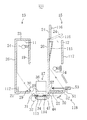
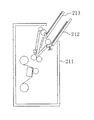
図22(a)に示すように、一般に普及しているプリンタ200では、プリンタ本体201の上側に給紙トレイ202が設けられ、プリンタ本体201の前側に排紙トレイ203が設けられている。しかし、このような構成では、図22(b)に示すように、プリンタ200を設置するために必要とされる設置スペース204は、プリンタ本体201に比較して相当大きなものとなる。そこで、設置スペースの低減を図るために、特開平11−334963号公報には、図23に示すように、薄型且つ縦長形状のプリンタ本体211を備え、給紙トレイ212と排紙トレイ213とがプリンタ本体211から斜め上方向に延びたいわゆる縦置き型のプリンタが提案されている。
【0003】
【発明が解決しようとする課題】
しかし、上記公報に開示されたプリンタでは、給紙トレイ212及び排紙トレイ213がプリンタ本体211から斜め上方向に突出していたため、両トレイ212,213の突出分だけ、余分な設置スペースが必要であった。したがって、設置スペースの更なる低減を図ることが困難であった。
【0004】
本発明は、かかる点に鑑みてなされたものであり、その目的とするところは、記録装置本体から突出する排紙トレイを削除することにより、記録装置のより一層の省スペース化を図ることにある。
【0005】
【課題を解決するための手段】
本発明に係る記録装置は、上方または斜め上方に開口する排出口が少なくとも形成された装置ケーシングと、前記装置ケーシング内に設けられ、記録媒体に対して記録を行う記録部と、前記装置ケーシング内に設けられ、前記記録部によって記録が行われた記録媒体を搬送する搬送手段と、前記装置ケーシング内において上下方向または斜め上下方向に延びるとともに前記排出口に連続する収容空間を区画形成し、前記搬送手段によって搬送された記録媒体を当該記録媒体の周囲全てを覆いつつ起立した状態に収容する収容部と、前記収容部に設けられ、記録媒体の取り出し時に、排出命令信号の入力により、前記収容部に収容された記録媒体の一部または全部を前記排出口から排出するように前記記録媒体を上方に搬送する上方搬送手段とを備えているものである。
【0006】
上記記録装置では、装置ケーシング内に設けられた収容部が収容空間を区画形成するとともに記録媒体を起立した状態に収容するので、従来のようなケーシングから斜め方向に突出する排紙トレイは不要となる。そのため、記録装置の設置スペースの低減が図られる。また、収容部は記録媒体の周囲全てを覆っているので、ユーザが記録直後の記録媒体に触れることがなく、記録媒体が汚れるおそれはない。
【0007】
さらに、記録媒体は、収容部に収容されているときにはその周囲全てを覆われているものの、排出の際には、排出命令信号の入力により、その一部または全部が上方搬送手段によって排出口から排出されることになる。そのため、記録媒体を容易に取り出すことができる。また、記録媒体の一部または全部が排出口から突出するので、記録媒体の排出状態を目視で確認することができる。
【0008】
前記記録装置は、収容部内の記録媒体の寸法を検出する寸法検出手段を備え、上方搬送手段は、記録媒体を排出口から所定の一定長さだけ突出させるように、前記寸法検出手段により検出された記録媒体の寸法に応じた量だけ前記記録媒体を上方に搬送するように構成されていることが好ましい。
【0009】
あるいは、前記記録装置は、記録媒体の寸法を入力する入力手段と、前記入力手段に入力された記録媒体の寸法を記憶する寸法記憶手段とを備え、上方搬送手段は、記録媒体を排出口から所定の一定長さだけ突出させるように、前記寸法記憶手段に記憶されている記録媒体の寸法に応じた量だけ前記記録媒体を上方に搬送するように構成されていてもよい。
【0010】
このことにより、記録媒体の寸法が異なっている場合であっても、上方搬送手段は、常に記録媒体を排出口から一定長さだけ突出させることになる。そのため、記録媒体を取り出す際に装置の上方に必要とされる取出用スペースは、記録媒体の寸法の相違に拘わらず一定となる。
【0011】
上方搬送手段は、記録媒体の下端部を支持する支持板と、当該支持板を上下移動させる駆動機構とを備えていてもよい。
【0012】
このことにより、上方搬送手段が簡易に構成される。
【0013】
収容部には、記録媒体の幅方向に移動することによって前記記録媒体の寸法に応じた所定位置に設定され且つ前記記録媒体の側辺部を規制する側板が設けられ、上方搬送手段は、前記側板の設定位置において分割され且つ前記記録媒体の下端部を支持する複数の分割板と、当該分割板を上下移動させる駆動機構とを備えていることが好ましい。
【0014】
このことにより、側板を記録媒体の寸法に応じた所定の位置に設定することにより、この側板が記録媒体の側辺部を規制することになる。そのため、記録媒体の幅方向のずれがなくなり、記録媒体の収容状態が向上する。記録媒体を支持する支持板が複数の分割板によって形成されているので、支持板の上下移動の際に支持板と側板との衝突が防止され、上方搬送動作は円滑に行われる。
【0015】
収容部には、記録媒体の幅方向に移動することによって前記記録媒体の寸法に応じた所定位置に設定され且つ前記記録媒体の側辺部を規制する側板が設けられ、上方搬送手段は、前記側板の設定位置に対応した位置に前記側板を挿通させる挿通口が形成され且つ前記記録媒体の下端部を支持する支持板と、当該支持板を上下移動させる駆動機構とを備えていてもよい。
【0016】
このことにより、記録媒体の収容状態が向上する。また、支持板には挿通口が形成されているので、支持板の上下移動の際に支持板と側板との衝突が防止され、上方搬送動作は円滑に行われる。
【0017】
前記記録装置は、収容部内の記録媒体の寸法を検出する寸法検出手段と、前記寸法検出手段の検出した記録媒体の寸法と前記側板の設定位置とが対応しているか否かを判定し、対応していないときには上方搬送手段の動作を中止させる保護機構とを備えていることが好ましい。
【0018】
あるいは、記録媒体の寸法を入力する入力手段と、前記入力手段に入力された記録媒体の寸法を記憶する寸法記憶手段と、前記寸法記憶手段に記憶されている記録媒体の寸法と前記側板の設定位置とが対応しているか否かを判定し、対応していないときには上方搬送手段の動作を中止させる保護機構とを備えていてもよい。
【0019】
このことにより、記録媒体の寸法と側板の設定位置とが対応していない状態で分割板または支持板が上下移動を行うことはなく、分割板または支持板と側板との衝突は未然に回避される。したがって、分割板または支持板と側板との破損を確実に防止することができ、装置の信頼性が向上する。
【0020】
前記記録装置は、収容部内の記録媒体の寸法を検出する寸法検出手段と、前記寸法検出手段の検出した記録媒体の寸法と前記側板の設定位置とが対応しているか否かを判定し、対応していないときには警告を発する警告手段とを備えていることが好ましい。
【0021】
あるいは、記録媒体の寸法を入力する入力手段と、前記入力手段に入力された記録媒体の寸法を記憶する寸法記憶手段と、前記寸法記憶手段に記憶されている記録媒体の寸法と前記側板の設定位置とが対応しているか否かを判定し、対応していないときには警告を発する警告手段とを備えていてもよい。
【0022】
このことにより、記録媒体の寸法と側板の設定位置とが対応していない場合には、警告手段によって警告が発せられるので、ユーザはそのことを迅速に認識することができる。
【0023】
前記記録装置は、有線または無線による排出命令信号が入力される排出スイッチを備え、上方搬送手段は、前記排出スイッチが入力されると搬送動作を開始するように構成されていてもよい。
【0024】
このことにより、記録媒体を取り出す必要がないときには、排出スイッチをOFFにすることにより記録媒体を収容部に収容しておく一方、記録媒体を取り出す必要があるときには、排出スイッチをONすることにより、記録媒体を容易に取り出すことができる。
【0025】
前記記録装置は、収容部への記録媒体の収容が完了すると所定の通知を行う通知手段を備えていてもよい。
【0026】
このことにより、通知手段による通知によって記録媒体の収容の完了を容易に認識することができる。
【0027】
前記記録装置は、排出口を開閉する開閉蓋を備えていることが好ましい。
【0028】
上記記録装置では、記録媒体を排出するとき以外は上記開閉蓋を閉鎖しておくことにより、収容部への塵や挨の侵入を防止することができる。
【0029】
記録部は、非接触式の記録ヘッドを有していることが好ましい。
【0030】
このことにより、非接触式の記録ヘッドは比較的小さな記録ヘッドであるので、装置の小型化及び薄型化が促進される。
【0031】
記録ヘッドは、インクジェットヘッドにより構成されていることが好ましい。
【0032】
インクジェットヘッドは様々な記録媒体に記録を行うことができるので、使用可能な記録媒体の種類が拡大する。また、高画質の記録を得ることができる。ヘッド自体が小型であるので、装置の小型化が促進される。
【0033】
【発明の効果】
以上のように、本発明によれば、記録媒体を起立した状態に収容する収容部を装置ケーシングの内部に設けることとしたので、設置スペースの低減を図ることができる。また、収容部は記録媒体の周囲全てを覆っているので、記録直後の記録媒体の汚れを防止することができる。さらに、排出命令信号の入力により記録媒体を排出口から排出する上方搬送手段を設けることにより、記録媒体を容易に取り出すことができる。
【0034】
【発明の実施の形態】
以下、本発明の実施の形態を図面に基づいて説明する。
【0035】
<実施形態1>
図1及び図2に示すように、実施形態1に係る記録装置は、いわゆる縦置き設置が可能なインクジェット式のプリンタ1である。プリンタ1はいわゆる横置き設置も可能であるが、以下では縦置き設置した場合について説明する。
【0036】
プリンタ1のケーシング10は、縦長の直方体形状に形成されている。ケーシング10の天板25の左側部には給紙口11が設けられ、右側部には排紙口12が設けられている。給紙口11及び排紙口12は、いずれも前後方向に細長い開口であり、上向きに開口している。給紙口11及び排紙口12には、それぞれ蓋23,24が設けられている。
【0037】
図2に示すように、ケーシング10には、天板25から下向きに延びる2つの区画板19,20と、ケーシング10内の下部において左側板26から右向きに延びる区画板21と、ケーシング10内の下部において右側板27から左向きに延びる区画板22とが設けられている。ケーシング10の内部はこれら区画板19,20,21,22によって仕切られており、ケーシング10の内部には、給紙部13と制御部16と記録部17と排紙部15とが形成されている。すなわち、ケーシング10内の左側部分には、左側板26と区画板19と区画板21とによって仕切られた給紙部13が形成されている。ケーシング10内の右側部分には、右側板27と区画板20と区画板22とによって仕切られた排紙部15が形成されている。ケーシング10内の中央部の下側部分には、インクジェットヘッド18を有する記録部17が形成されている。記録部17の上側には、区画板19と区画板20とによって仕切られた制御部16が形成されている。なお、制御部16と記録部17とは、本体部70を構成している。
【0038】
給紙部13の左側板26と区画板19と区画板21とは、印字前の記録紙を収容する供給側収容部を形成している。区画板19には、記録紙40の紙倒れを防止するための紙倒れ防止機構54が設けられている。紙倒れ防止機構54は、区画板19に固定されたバネ55と、バネ55の先端に固定されたローラ56とを備えている。この紙倒れ防止機構54は、バネ55の付勢力によって記録紙40の上端部を左側板26側に押さえつけることにより紙倒れを防止する一方、ローラ56の回転によって記録紙40の搬送を円滑化するものである。
【0039】
給紙部13には、区画板21と左側板26とに立て掛けられた傾斜板28と、区画板21上の先端側(図2の右側)に設けられた埋没自在な突起29とが設けられている。傾斜板28の下端部に対向する位置には、ピックアップローラ30が設けられている。これら傾斜板28、突起29及びピックアップローラ30は、給紙部13内の記録紙40を記録部17側に向かって一枚毎に送り出すための用紙送り出し手段を構成している。給紙部13内の紙を送り出す際には、突起29が区画板21内に埋没するとともに傾斜板28の傾き度合いが大きくなり、傾斜板28上の記録紙40の下端部がピックアップローラ30と接触する。そして、ピックアップローラ30が回転することにより、傾斜板28上の最も上側に位置する記録紙40のみが記録部17側に送り出されることになる。
【0040】
ピックアップローラ30の下方には、前後方向(図2の紙面表裏方向)に複数配列されたピンチローラ(分割ローラ)31と、これらピンチローラ31と対向するように配置された駆動ローラからなる給紙ローラ32とが設けられている。ピックアップローラ30とピンチローラ31と給紙ローラ32とは、上下方向に一直線上に並んでいる。そのため、ピックアップローラ30と給紙ローラ32とは、上下方向にオーバーラップしている。ピンチローラ31の左方には、給紙部13から記録部17に向かって延びるガイド板33が設けられている。このガイド板33は、給紙部13から搬送される記録紙40の先端部を給紙ローラ32とピンチローラ31との間に導くものである。なお、ピックアップローラ30とピンチローラ31と給紙ローラ32とは、供給側搬送機構を構成している。
【0041】
図3に示すように(なお、図2においては、記録部17の詳細な構成は省略している。)、記録部17は、記録ヘッドとしてのインクジェットヘッド18と、インクジェットヘッド18にインクを供給するインクタンク36とを備えている。本実施形態のインクジェットヘッド18は、ピエゾ式のインクジェットヘッドである。ただし、記録ヘッドには、バブル式のインクジェットヘッド等、その他のヘッドを用いてもよい。インクタンク36はインクジェットヘッド18に一体的に取り付けられている。インクジェットヘッド18及びインクタンク36は、前後方向(図3の左右方向)に延びるキャリッジ軸37に対して往復移動自在に取り付けられている。キャリッジ軸37の下方には、インクジェットヘッド18のヘッド面と対向するように配置されたプラテン34が設けられている。
【0042】
プラテン34の後側には、インクジェットヘッド18が非記録位置にあるときにインクジェットヘッド18のヘッド面を覆うキャップ38が設けられている。キャップ38にはインク排出用のチューブ39が取り付けられており、このチューブ39にはインク吸引機構41が設けられている。インク吸引機構41は、インクジェットヘッド18のインクをキャップ38内に吸引除去し、さらにキャップ38内のインクをチューブ39を通じてインク容器42に排出するものである。インク吸引機構41の構成は特に限定されるものではなく、例えば図4(a)及び(b)に示すように、吸引弁43及び排出弁44を備えた蛇腹状の伸縮体45によって構成されたポンプであってもよい。
【0043】
インクジェットヘッド18は、ノズル内のインクの増粘を防止するために、非記録位置において間欠的に全ノズルからインクを吐出するように構成されている。図3に示すように、プラテン34の前側には、そのように吐出されたインクを回収するインク容器35が設けられている。なお、キャップ38、インク容器42及びインク容器35の内部には、主としてインクの飛散を防止するために、スポンジ等からなるインク吸収体46が設けられている。
【0044】
図2に示すように、プラテン34の右方には、駆動ローラからなる排紙ローラ47と、排紙ローラ47と対向するように配置された拍車ローラ48とが設けられている。拍車ローラ48は、前後方向に所定間隔毎に配列された複数の小ローラからなっている。拍車ローラ48は、記録紙40を所定間隔毎に押さえつけることによって記録紙40に適度な張力を与え、ジャム(紙詰まり)の発生を防止している。
【0045】
インクジェット方式の記録では、記録紙40にインク滴を着弾させてインクドットを形成するが、記録紙40にインク滴が着弾すると、インクに含まれる溶媒は直ちに蒸発する。すると、記録紙40の収縮が起こり、そのままでは記録紙40に皺や波打ちが発生し、インクジェットヘッド18と記録紙40との間の間隔が変動して記録の品質が低下しやすい。そこで、本実施形態では、排紙ローラ47の対向ローラとして拍車ローラ48を用い、記録紙40に張力を与えることによって、記録紙40のプラテン34上の領域を平坦な面にしている。また、拍車ローラ48は、インクドットが形成された直後の記録面と直接接触するため、記録面との接触面積は小さい方がよい。そこで、本プリンタ1では、拍車ローラ48を、複数の小ローラからなるいわゆる分割拍車ローラによって形成することとした。
【0046】
プラテン34の右側部の上方には、記録紙40を排紙ローラ47と拍車ローラ48との間に導くガイド板49が設けられている。ガイド板49は水平方向に延びる板状部材からなり、その左端部は記録紙40を導入しやすいように上方に傾斜している。
【0047】
排紙ローラ47及び拍車ローラ48の右方には、記録紙40の搬送経路を排紙部15に向かって右斜め上方に変更させる経路変更板50が設けられている。
【0048】
経路変更板50の右上方には、駆動ローラ51と対向ローラ52とが設けられている。駆動ローラ51及び対向ローラ52の上方には、左右方向に移動自在な押し込み体53が設けられている。押し込み体53は、駆動ローラ51及び対向ローラ52によって搬送された記録紙40の後端部を排紙部15内に押し込むものである。本実施形態では、押し込み体53は平板形状に形成されているが、押し込み体53の形状は特に限定されるものではなく、円柱形状、角柱形状等、他の形状であってもよい。なお、排紙ローラ47、拍車ローラ48、経路変更板50、駆動ローラ51、及び対向ローラ52は、排出側搬送機構(搬送手段)を構成している。
【0049】
排紙部15の右側板27と区画板20と区画板22とは、記録後の記録紙40を収容する排紙側収容部を形成している。給紙部13と同様、排紙部15の区画板20にも、バネ55及びローラ56を有する紙倒れ防止機構54が設けられている。区画板22の先端部は、収容した記録紙40を脱落させないように上方に屈曲している。
【0050】
また、排紙部15には、上方搬送手段として、図示しない駆動機構によって上下移動自在な移動板57が設けられている。移動板57の上面は平滑面であり、記録紙40の後端部を支持する支持面を形成している。移動板57は、記録時には排紙部15の底部(つまり、区画板22の表面上)に位置する一方、記録紙40を排紙口12から取り出す際には、上方に移動する。このように移動板57が上方に移動することにより、記録紙40は排紙口12から所定長さ分だけ突出する。したがって、ユーザは記録紙40の上端部をつまんで引き出すことによって、排紙部15の内部に手を挿入することなく記録紙40を容易に取り出すことができる。
【0051】
移動板57は、記録紙40の後端部を上方に移動させるためのものであれば何でもよく、金属、プラスチック、セラミックスや、それらの複合体等を好適に使用することができる。また、移動板57の形状は特に限定されず、例えば、板状、棒状、矩形、円形、三角形や多角形等の形状であってもよい。
【0052】
図5に示すように、排紙部15には、記録紙40の側辺部を規制する用紙隔壁60が設けられている。用紙隔壁60は前後方向(つまり、記録紙40の幅方向)に移動自在な平板であり、記録紙40の用紙サイズに応じて手動または自動で上記方向に移動する。
【0053】
移動板57には、移動板57の上下移動の際に用紙隔壁60を挿通させる第1及び第2の挿通口64,65が形成されている。第1挿通口64は、記録紙40がA6サイズの用紙の場合に用紙隔壁60が設定される位置に形成されている。第2挿通口65は、記録紙40がA5サイズの用紙の場合に用紙隔壁60が設定される位置に形成されている。このように挿通口64,65が形成されていることにより、記録紙40の取り出しの際に移動板57と用紙隔壁60との衝突が防止され、移動板57の円滑な昇降動作が確保されている。
【0054】
なお、制御部16には、給紙部13に収容された用紙サイズを検出する用紙サイズ検出器71と、用紙隔壁60の設定位置が記録紙40の用紙サイズに対応しているか否かを判定し、対応していないときに警告を発するアラーム機構72とが設けられている。用紙サイズ検出器71は、用紙サイズを自動的に検出するものであってもよい。また、用紙サイズをユーザの手動による設定入力により検出するものであってもよい。例えば、用紙サイズ検出器71は、ユーザが記録紙40のサイズを入力する入力部(図示せず)と、当該入力部に入力された記録紙40のサイズを記憶する記憶部(図示せず)とを備えていてもよい。また、入力は、例えばパソコンやリモコン等における操作によって行われてもよい。つまり、入力を遠隔操作で行ってもよい。
【0055】
アラーム機構72には、警告音を発信する機構や、プリンタ1の表示部(図示せず)に所定の警告を表示させる機構等を用いることができる。また、アラーム機構72は、プリンタ1の破損を防止するため、用紙隔壁60の設定位置が記録紙40の用紙サイズに対応しているか否かを判定し、対応していないときに移動板57の移動を強制的に中止させる保護機構(図示せず)を備えていてもよい。
【0056】
図6に示すように、移動板57の上昇位置は、排紙口12から突出する記録紙40の突出長さLが一定となるように、記録紙40の用紙サイズに応じて異なっている。すなわち、移動板57は、用紙サイズが小さいほど高い位置にまで上昇するように構成されている。例えば、図6(a)に示すように、記録紙40aがA6サイズの用紙の場合には、移動板57は最も上方の第1位置にまで上昇する。図6(b)に示すように、記録紙40bがA5サイズの用紙の場合には、移動板57は上記第1位置よりも低い第2位置にまで上昇する。図6(c)に示すように、記録紙40cがA4サイズの用紙の場合には、移動板57は最も低い第3位置にまで上昇する。したがって、用紙サイズの異なる複数種類の記録紙40a〜40cを用いた場合であっても、各記録紙40a〜40cの排紙口12からの突出長さは一定となり、記録紙40a〜40cの取り出し作業は容易になる。また、用紙サイズの大きな記録紙40cを取り出す場合であっても、プリンタ1の上方に必要とされる空間は小さくてすむ。そのため、設置スペースを低減することができる。
【0057】
図1に示すように、ケーシング10の前面には、排出スイッチ58と、排出完了表示部59とが設けられている。排出スイッチ58は、ユーザが排紙部15の記録紙40を取り出す際に入力するスイッチである。当該排出スイッチ58の入力により、排紙部15の蓋24が開放されるとともに移動板57が上昇し、排紙口12から記録紙40の一部が突出する。これにより、ユーザは記録紙40を容易に取り出すことができる。排出スイッチ58は、押しボタンスイッチ等の公知のスイッチの他、リモコン等によって遠隔操作される各種スイッチ等によって構成することができる。排出完了表示部59は、排紙部15内の記録紙40の有無を通知するための表示部であり、記録紙40の排紙部15への収容が完了して排紙部15内に記録紙40が残っているときには点灯し、記録紙40の取り出しが完了すると消灯する。ただし、排出完了表示部59の表示方法は特に限定されるものではなく、記録紙40の取り出しが完了したときに点灯するように構成されていてもよい。また、排出完了表示部59は独立した表示部であってもよく、プリンタ1の各種設定のために用いられる表示部(図示せず)と兼用されていてもよい。
【0058】
以上のように、本実施形態に係るプリンタ1では、給紙部13及び排紙部15は上向きに延びており、本体部70は給紙部13と排紙部15との間に設けられている(図2参照)。また、給紙部13から記録部17に至る搬送経路及び記録部17から排紙部15に至る搬送経路は、それぞれ記録紙40の搬送方向を略直角方向に変化させるように形成されている。給紙部13から排紙部15に至る搬送経路の全体は、略U字型に形成されている。
【0059】
図7に示すように、記録部17から排紙部15に向かう搬送経路の変更角度θ、つまり記録部17における搬送方向D1と排紙部15に向かう搬送方向D2とのなす角の角度θは、90度〜180度となっている。なお、角度θは90度〜150度が好ましく、110度〜130度が特に好ましい。本実施形態では、上記角度θは約120度に設定されている。このように角度θを90度〜180度とした理由は、記録紙40自体の復元力によって記録紙40をプラテン34に押しつけ、記録面を平坦化するためである。
【0060】
図1及び図2に示すように、給紙部13の給紙口11と排紙部15の排紙口12とは、天板25と同じ高さに設けられている。また、蓋23,24を閉じた状態において、ケーシング10の上面は面一となる。したがって、ケーシング10の上に記録紙等を一時的に載置することができ、プリンタ1の上方のスペースを有効活用することができる。
【0061】
次に、図2を参照しながら、給紙から排紙に至るまでの動作について説明する。
【0062】
給紙の際には、まず、給紙部13の蓋23が開放され、給紙口11から記録紙40が挿入される。挿入された記録紙40は、それらの下辺部が突起29によって支持された状態で、給紙部13内に収容される。通常は複数枚の記録紙40が収容されるが、1枚の記録紙40のみを収容してもよいことは勿論である。
【0063】
記録動作の際には、突起29が埋没すると同時に、傾斜板28の下端部が右側に移動するように傾斜板28が移動する。これにより、傾斜板28上の最も上側に位置する記録紙40がピックアップローラ30と接触し、ピックアップローラ30の回転によって上記記録紙40が取り出される。そして、この記録紙40は、給紙ローラ32によって記録部17に搬送される。
【0064】
記録部17においては、インクジェットヘッド18から記録紙40に向かってインク滴が吐出される。これらインク滴は記録紙40に着弾し、記録紙40上に複数のインクドットを形成する。そして、これらインクドットにより、記録紙40上に所望の画像等が形成される。
【0065】
画像等が形成された記録紙40は、排紙ローラ47によって搬送され、経路変更板50によって搬送経路を変えた後、駆動ローラ51によって排紙部15に搬送される。排紙部15に搬送された記録紙40は、その後端部が押し込み体53によって右方向に押し込まれることにより、排紙部15内に起立した状態で収容される。なお、起立した状態とは、例えば図8(a)〜(e)のいずれかに示されたような状態をいう。
【0066】
上述の搬送動作及び記録動作は記録紙40ごとに連続して行われ、その結果、排紙部15に複数枚の記録紙40が収容される。その後は、ユーザが排出スイッチ58をONすることにより、排紙部15の蓋24が開放され、移動板57の上昇によって記録紙40が上方に持ち上げられる。その結果、記録紙40の一部が排紙口12から突出することになり、ユーザは記録紙40を容易に取り出すことができる。
【0067】
なお、上記説明では、プリンタ1を縦置き設置した場合を説明したが、本プリンタ1は横置き設置も可能である。なお、横置き設置の場合には、移動板57は上下方向に移動する代わりに水平方向に移動することになる。具体的には、図9に示すように、記録紙40を水平状態で供給及び排出するように横置きすることができ、また、図10に示すように、記録紙40を垂直状態で供給及び排出するように横置きすることも可能である。本プリンタ1は、設置スペース及び設置環境に応じて、縦置き及び横置きのいずれの設置態様も自由に選択することができる。
【0068】
以上のように、本プリンタ1では、給紙部13及び排紙部15が互いに平行に形成されているので、プリンタの全体形状が薄型になっている。したがって、プリンタの小型化を促進することができ、設置スペースの削減を図ることができる。従来のようにプリンタ専用のラック等は不要となり、例えば、縦置き設置する場合には、テレビの横やタワー型パソコンの側方などの小さなスペースにも設置することが可能となる。また、リビングに置いても、違和感なく使用することができる。
【0069】
縦置き設置の場合に、給紙部13及び排紙部15のそれぞれが鉛直方向に延びる状態となるので、プリンタ1は転倒しにくくなる。特に、本実施形態では、給紙部13と排紙部15とは本体部70を挟んで反対側に配置されているので、プリンタ1の全体の重心は、ケーシング10の中央部に位置しやすくなる。そのため、プリンタ1の転倒のおそれは少ない。また、記録動作時の振動が抑制される。したがって、記録動作は安定し、印字品質は向上する。
【0070】
ピックアップローラ30と給紙ローラ32とがケーシング10の長手方向にオーバーラップしているので、ケーシング10の幅を薄くすることができる。
【0071】
記録部17の記録ヘッドとしてインクジェットヘッド18を用いているので、記録部17を小型化することができる。また、高画質の画像を得ることができる。
【0072】
記録部17における搬送方向D1と排紙部15に向かう搬送方向D2とのなす角の角度θが180度よりも小さいので、プラテン34上の記録紙40は、記録紙40自体の復元力によってプラテン34側に押さえつけられる。したがって、記録紙40の後端部がプラテン34上から跳ね上がることはない。そのため、記録紙40の記録面の位置が変動することがなく、記録品質は向上する。また、記録紙40の後端部がインクジェットヘッド18に接触するおそれがなく、記録紙40によるインクジェットヘッド18の損傷は起こらない。
【0073】
ところで、記録紙40に張力を与えるための拍車ローラ48として分割拍車ローラを用いる装置では、拍車ローラ48だけでは記録紙40に与えられる張力は小さくなりやすい。また、記録紙40に与えられる張力は不均一になりやすい。しかし、本実施形態のプリンタ1では、記録紙40自体の復元力によって記録紙40がプラテン34側に押さえつけられるので、記録紙40の全体が適度な力で且つ均一にプラテン34に押しつけられる。したがって、分割拍車ローラを用いているにも拘わらず、記録紙40の記録面を十分に平坦化することができる。
【0074】
縦置き設置の場合に、排紙部15に導入された記録紙40の後端部を押し込み体53によって排紙部15側に押し込むこととしたので、ジャムの発生をより確実に防止することができる。すなわち、複数枚の記録紙40を連続印刷する際に、先に印字された記録紙40の後端部が駆動ローラ51及び対向ローラ52の近傍に残っていると、後から印字された記録紙40の先端部が先の記録紙40の後端部と接触し、ジャムを発生しやすくなる。しかし、本実施形態によれば、先の記録紙40の後端部は押し込み体53によって排紙部15の右側板27側に押し込まれるので、先の記録紙40が後の記録紙40の搬送経路を邪魔することがなく、ジャムの発生は未然に防止される。
【0075】
記録部17はケーシング10の下部に設けられ、その周りを覆われているので、ユーザが誤って記録部17に触れることはない。したがって、ユーザが誤って記録部17を破損させるおそれはない。
【0076】
また、印字された記録紙40は、周囲を覆われた排紙部15に収容される。そのため、直ちにプリンタ1の外部に排出される従来のプリンタと異なり、ユーザが印字直後の記録紙40の記録面に触れるおそれはない。したがって、記録紙40の記録面が十分に乾燥してから記録紙40を取り出すことになるので、印字のにじみ等は防止される。
【0077】
給紙部13及び排紙部15には開閉自在な蓋23,24がそれぞれ設けられているので、給紙部13及び排紙部15に塵や挨が入り込むことを防止することができる。したがって、プリンタ1の信頼性及び寿命を向上させることができる。
【0078】
排出完了表示部59を設けたので、ユーザが排紙部15における記録紙40の有無を容易に把握することができる。
【0079】
排出スイッチ58を設け、排出スイッチ58を入力したときに排紙部15の蓋24を開放することとしたので、記録紙40の取り出しのときにだけ排紙部15を開放することができる。
【0080】
−変形例−
なお、記録紙40を上昇させる移動板57は、一枚の板に挿通口64,65を設ける代わりに、図11に示すように、互いに分離された複数の移動板61,62,63から構成されていてもよい。この場合、移動板61,62,63のすべてを昇降させてもよく、用紙サイズに応じて1または2の移動板のみを昇降させてもよい。
【0081】
搬送経路の変更角度θは前述した値に限らず、記録紙40の後端部が下向きに力を受ける限り、どのような値でもよく、0度以上且つ180度未満の範囲内で任意の値をとることができる。
【0082】
上記実施形態では、ユーザが排出スイッチ58をONすることにより記録紙40を取り出すようにしていたが、このような手動の操作に限らず、所定の記録動作が終了すると蓋24の開放及び移動板57の移動が自動的に行われるように構成されていてもよい。
【0083】
また、給紙部13の左側板26と区画板19と区画板21とで、印字前の記録紙40を収容する供給側収容部を形成したが、供給側収容部をカセットで構成してもよい。また、排紙部15の右側板27と区画板20と区画板22とで、印字後の記録紙40を収容する排紙側収容部を形成したが、排紙側収容部をカセットで構成してもよい。このようにすることにより、記録紙40を1回で纏めて収容する場合や、纏めて取り出したりする場合に、利便性が向上する。
【0084】
<実施形態2>
図12に示すように、実施形態2に係るプリンタ100は、排紙部15の区画板22を記録部17のプラテン34の表面よりも低い位置に設け、記録部17からの記録紙40を排紙部15に導く駆動ローラ51及び対向ローラ52等(図2参照)を省略することとしたものである。
【0085】
本プリンタ100では、排紙部15の排紙口12は給紙部13の給紙口11よりも低い位置に設けられており、排紙部15の上部には段差部が設けられている。ただし、実施形態1と同様に排紙口12を給紙口11と同じ高さに設けてもよいことは勿論である。排紙部15の区画板22は、給紙部13の区画板21よりも低い位置に設けられている。
【0086】
本プリンタ100は、記録部17から排紙部15に搬送された記録紙40を排紙部15に押し込む押込手段として、実施形態1のようなスライド移動式の押し込み体53ではなく、図13(a)及び(b)に示すように、回転式の押し込み板101を備えている。押し込み板101は、記録紙40の用紙サイズに応じて分割された複数の板、すなわち第1押し込み板102と第2押し込み板103と第3押し込み板104とから構成されている。押し込み板102〜104の上端部は、回転軸105に固定されている。これにより、回転軸105を回転させることによって、押し込み板101は上端部を中心として回転する。記録紙40を排紙部15に搬送する際には、押し込み板101は記録部17側に傾き(図13(b)参照)、排紙部15の導入部分の空間を大きくすることによって記録紙40の搬送を容易にする。一方、記録紙40を排紙部15に収容した後は、押し込み板101は右側板27側に傾き(図13(a)参照)、紙倒れ防止機構54(図13においては図示せず)によって記録紙40を排紙部15の右側板27側に押しつける。
【0087】
排紙部15には、前後方向(つまり、用紙の幅方向)に移動自在な用紙隔壁106が設けられている。この用紙隔壁106は、排紙部15の収容空間を記録紙40のサイズに応じた大きさに調整するためのものである。押し込み板102〜104の押し込み動作の際に押し込み板102〜104が用紙隔壁106とぶつからないように、各押し込み板102〜104の間には、用紙隔壁106の厚みよりも幅の広い隙間が形成されている。
【0088】
第1押し込み板102は、A6サイズの記録紙40に対応した大きさに形成されている。第2押し込み板103は、第1押し込み板102と共同することによってA5サイズの記録紙40に対応する大きさに形成されている。第3押し込み板104は、第1押し込み板102及び第2押し込み板103と共同することによってA4サイズの記録紙40に対応する大きさに形成されている。そして、記録紙40がA6サイズの用紙の場合には、用紙隔壁106は第1押し込み板102と第2押し込み板103との間に設定される。一方、記録紙40がA5サイズの用紙の場合には、用紙隔壁106は第2押し込み板103と第3押し込み板104との間に設定される。記録紙40がA4サイズの用紙の場合には、用紙隔壁106は第3押し込み板104の後側(図13(a)に示す左側)に設定される。
【0089】
また、本プリンタ100では、移動板57もまた、用紙サイズに応じて第1移動板107、第2移動板108及び第3移動板109に分割されている。図示は省略するが、移動板107〜109には、これら移動板107〜109を上下移動させる駆動機構が設けられている。第1〜第3移動板107〜109の間にも、用紙隔壁106よりも幅の大きな隙間が形成されている。
【0090】
なお、押し込み板101の各板102〜104は、一体となって回転するように形成されていてもよく、個別に回転するように形成されていてもよい。また、移動板57の各板107〜109も、一体となって移動するように形成されていてもよく、個別に移動するように形成されていてもよい。
【0091】
本実施形態のプリンタ100も、実施形態1のプリンタ1と同様、縦置き設置及び横置き設置の両方の設置態様が可能である。
【0092】
本実施形態では、区画板22をプラテン34の表面よりも低い位置に設けたので、排紙ローラ47から搬送された記録紙40を排紙部15に導入するための導入機構(実施形態1における駆動ローラ51及び対向ローラ52など)は不要となる。したがって、部品点数の削減及びプリンタの更なる小型化が可能となる。また、排紙経路が短縮化されるので、排紙に必要な時間を短くすることができる。 押し込み板101が回転式に形成されているので、実施形態1と異なり、記録部17と排紙部15との間に押し込み体を収容するためのスペースを設ける必要がない。したがって、プリンタを更に小型化することができる。
【0093】
−変形例−
上記実施形態では、排紙部15の区画板22及び移動板57は、水平方向に延びる平板形状に形成されていた。しかし、図14に示すように、区画板22及び移動板57を記録部17側に向かって上方に傾斜する傾斜板によって形成してもよい。区画板22及び移動板57を記録部17に向かって上方に傾斜するように形成することにより、記録紙40の下端部は右側板27側に移動しようとする力を受ける。したがって、図15(a)に示すような記録紙40のたわみを防止することができ、図15(b)に示すように、記録紙40を直立状態に保持することが容易になる。
【0094】
図16に示すように、紙倒れ防止機構54を押し込み板101と制御部16との間に設けてもよい。このように紙倒れ防止機構54を押し込み板101の制御部16側に設けることにより、プリンタ100を横置きした場合に、押し込み板101の上面(右側板27側の面)に記録紙40を載置することが容易になる。つまり、押し込み板101の上面に紙倒れ防止機構54が設けられていないので、押し込み板101の上面は平らな面となり、記録紙40を容易に積層することができる。したがって、記録紙40を整理した状態で収容することができ、記録紙40の収容状態を向上させることができる。
【0095】
横置き設置の場合には、排紙ローラ47と拍車ローラ48との間から排紙部15に向かって記録紙40が導入される際に、移動板57を若干量だけ水平方向に移動させることにより、記録紙40の後縁部を排紙部15の内部に押し出すことが好ましい。これにより、記録紙40は排紙部15内の適正な位置に導かれることになる。
【0096】
横置き設置の場合には、記録紙40のサイズによっては、排紙部15に導入したときに記録紙40の先端部が排紙部15の蓋24に接触し、記録紙40の先端部がたわんでしまうおそれがある。そのような場合は、蓋24を開放した状態で記録紙40を排紙部15に導入することが好ましい。蓋24は、記録紙40を排紙部15に導入する際に自動的に開放するように構成されていてもよい。
【0097】
<実施形態3>
図17に示すように、本実施形態に係るプリンタ110は、排紙部15の区画板22を記録部17側に向かって下方に傾斜するように形成し、区画板22に記録紙40の搬送経路の変更機能を持たせることにより、経路変更板50(図2参照)を省略したものである。
【0098】
プリンタ110の区画板22は、排紙ローラ47及び拍車ローラ48の右側近傍にまで延びており、区画板22の先端部はプラテン34の表面よりも低い位置にある。そのため、排紙ローラ47と拍車ローラ48との間を通過した記録紙40は、その先端が区画板22上を移動することにより、搬送経路が右向き方向から徐々に上向き方向に変更される。このように、本実施形態では、排紙部15の区画板22が搬送経路の一部を形成している。
【0099】
本実施形態では、区画板22が移動板57を兼ねている。この場合、用紙サイズの異なる複数の記録紙の突出長さを一定にすることができ、取り出し作業が容易になる。また、構成が簡素化され、装置の更なる小型化が可能になり、かつコストダウンを図ることができる。
【0100】
以上のように、本実施形態によれば、経路変更板50を省略することができ、部品点数の削減を図ることが可能となる。また、排紙経路を更に短縮することができ、排紙時間を一層短くすることができる。
【0101】
なお、本プリンタ110も、縦置き設置及び横置き設置の両方の設置態様が可能である。
【0102】
<実施形態4>
図18に示すように、実施形態4に係るプリンタ111は、記録部17から排紙部15への記録紙40の挿入を、排紙部15の右側から行うようにしたものである。
【0103】
本実施形態では、給紙部13の用紙送り出し手段は、傾斜板28の代わりに、記録紙40の下端部を記録部17側に押し込む押し込み板112を備えている。したがって、本実施形態における用紙送り出し手段は、押し込み板112、突起29及びピックアップローラ30によって構成されている。なお、押し込み板112は、プリンタ111を縦置き設置した場合には左右方向に移動し、横置き設置した場合には上下方向に移動することになる。
【0104】
記録部17のプラテン34の上方には、記録紙40をインクジェットヘッド18とプラテン34との間に導くガイド板113,114が設けられている。
【0105】
排紙部15の右側板117の下側には、経路変更板50によって搬送経路が変更された記録紙40を導入する導入口118が形成されている。本実施形態では、駆動ローラ51及び対向ローラ52は、導入口118に設けられている。
【0106】
本実施形態では、印字された記録紙40は、排紙部15の区画板20上に堆積していく。そのため、記録紙40が堆積する面を収容側壁面と称するとすると、給紙部13の収容側壁面(つまり左側板26)と排紙部15の収容側壁面(区画板20)とは、同一の側(図18の左側)に位置することになる。したがって、図19に示すように、プリンタ111を横置きした場合に、給紙部13の収容側壁面と排紙部15の収容側壁面とを、共に下面とすることができる。また、横置き設置の場合に、排紙部15の導入部分は上側に位置することになるので、排紙部15への記録紙40の搬送が容易になる。
【0107】
なお、横置き設置の場合に記録紙40の取り出しを容易にするために、排紙部15の区画板20に、排紙口12に向かって上向きに傾斜する傾斜板115を設けるようにしてもよい。また、蓋24を開いた状態で記録紙40の先端部をつかみやすいように、記録紙40の先端部を持ち上げる突起116を蓋24の内面に設けるようにしてもよい。
【0108】
本実施形態に係るプリンタ111も、縦置き設置及び横置き設置の両方の設置態様が可能である。
【0109】
<実施形態5>
図20に示すように、実施形態5に係るプリンタ120は、給紙部13と排紙部15とを隣接させ、記録部17を排紙部15の外側に設けたものである。
【0110】
本実施形態では、区画板21の突起29の右方に、ピックアップローラを兼ねる給紙ローラ121が設けられている。給紙ローラ121の右側には、対向ローラ122が設けられている。記録部17は、給紙ローラ121の右斜め上に設けられている。記録動作の際に記録紙40が上下方向に搬送されるように、給紙ローラ121と対向ローラ122との隙間、インクジェットヘッド18とプラテン34との隙間、及び排紙ローラ47と拍車ローラ48との隙間は、上下方向に並んでいる。本実施形態では、排紙部15の右側板は実施形態2と同様の押し込み板101によって形成されている。
【0111】
なお、本実施形態に係るプリンタ120も、縦置き設置及び横置き設置の両方の設置態様が可能である。
【0112】
<その他の実施形態>
上記各実施形態では、給紙部13及び排紙部15の長手方向は、それぞれケーシング10の底面と直交していた。しかし、例えば図21(a)〜(c)に示すように、給紙部13及び排紙部15は、それらの長手方向がケーシング10の底面から傾斜していてもよい。ただし、装置の安定性を高めるために、給紙部13及び排紙部15は、それらの長手方向が同一の方向に傾いていないことが好ましい。つまり、給紙部13の長手方向と排紙部15の長手方向とは、いずれか一方のみが傾いているか、あるいは、互いに逆の方向に傾いていることが好ましい。具体的には、給紙部13の長手方向とケーシング10の底面90とのなす角の角度θ1は90度〜120度が好ましく、排紙部15の長手方向とケーシング10の底面90とのなす角の角度θ2も90度〜120度が好ましい。上記角度θ1とθ2とが同一の値であれば、左右の対称性が保たれ、安定性が更に向上するのでより好ましい(図21(c)参照)。
【0113】
記録部17の記録ヘッドは、インクジェットヘッド18に限らず、他のヘッドでもよい。ただし、記録部17の小型化のためには、非接触印字方式の記録ヘッドが好ましい。例えば、レーザ露光による感熱記録方式のヘッド、トナーを飛翔させることによって記録を行うトナージェット方式のヘッド等を好適に用いることができる。
【0114】
給紙口11または排紙口12は、斜め上方向に開口していてもよく、給紙部13または排紙部15は斜め上方向に延びていてもよい。
【0115】
記録媒体は記録用紙40に限定されるものではなく、OHP用のフィルムなど、その他のシート状記録媒体であってもよい。
【0116】
本発明の適用対象はプリンタに限定されず、複写機やFAX等、他の記録装置であってもよい。
【図面の簡単な説明】
【図1】 プリンタを縦置き設置した場合の斜視図である。
【図2】 プリンタの内部構造を示す断面図である。
【図3】 記録部の要部の概略構成図である。
【図4】 (a)及び(b)は、インク吸引機構の断面図である。
【図5】 排紙部の要部の斜視図である。
【図6】 (a)〜(c)は、用紙サイズに応じた支持板の上昇位置を説明する概念図である。
【図7】 記録紙の搬送経路を説明する記録部近傍の正面図である。
【図8】 (a)〜(e)は、排紙部の断面図である。
【図9】 プリンタを横置き設置した場合の斜視図である。
【図10】 プリンタを横置き設置した場合の斜視図である。
【図11】 排紙部の変形例の斜視図である。
【図12】 プリンタの内部構造を示す断面図である。
【図13】 (a)及び(b)は、排紙部の要部の斜視図である。
【図14】 プリンタの内部構造を示す断面図である。
【図15】 排紙部における記録紙のたわみ状態を説明するための図であり、(a)は支持板が水平な場合、(b)は支持板が傾斜している場合を示す。
【図16】 プリンタの内部構造を示す断面図である。
【図17】 プリンタの内部構造を示す断面図である。
【図18】 プリンタの内部構造を示す断面図である。
【図19】 プリンタの内部構造を示す断面図である。
【図20】 プリンタの内部構造を示す断面図である。
【図21】 (a)〜(c)は、給紙部と排紙部とケーシング底面との位置関係を説明する模式図である。
【図22】 (a)は従来のプリンタの斜視図、(b)は従来のプリンタの側面図である。
【図23】 従来のプリンタの要部断面図である。
【符号の説明】
10 ケーシング(装置ケーシング)
11 給紙口
12 排紙口(排出口)
13 給紙部
14 本体部
15 排紙部(収容部)
16 制御部
17 記録部
18 インクジェットヘッド(記録ヘッド)
32 給紙ローラ
34 プラテン
36 インクタンク
40 記録紙(記録媒体)
50 経路変更板
53 押し込み体
54 紙倒れ防止機構
57 移動板(上方搬送手段,支持板)
60 用紙隔壁(側板)
61,62,63 移動板(分割板)
64,65 挿通口[0001]
BACKGROUND OF THE INVENTION
The present invention relates to a recording apparatus.
[0002]
[Prior art]
As shown in FIG. 22A, in the
[0003]
[Problems to be solved by the invention]
However, in the printer disclosed in the above publication, since the paper feed tray 212 and the
[0004]
The present invention has been made in view of the above points, and an object of the present invention is to further reduce the space of the recording apparatus by deleting the paper discharge tray protruding from the recording apparatus main body. is there.
[0005]
[Means for Solving the Problems]
A recording apparatus according to the present invention includes an apparatus casing having at least a discharge port that opens upward or obliquely upward, a recording unit that is provided in the apparatus casing and performs recording on a recording medium, and the apparatus casing A conveying means for conveying a recording medium recorded by the recording unit, and a housing space extending in the vertical direction or diagonally up and down direction in the apparatus casing and continuing to the discharge port, The recording medium conveyed by the conveying means is arranged around the recording medium. all A storage portion that is housed in a standing state while covering, and provided in the storage portion, when taking out the recording medium, By inputting the discharge command signal And an upper conveying means for conveying the recording medium upward so that a part or all of the recording medium accommodated in the accommodating portion is discharged from the discharge port.
[0006]
In the recording apparatus, since the storage portion provided in the apparatus casing defines the storage space and stores the recording medium in an upright state, there is no need for a discharge tray that protrudes obliquely from the conventional casing. Become. Therefore, the installation space for the recording apparatus can be reduced. Also, the storage area is around the recording medium. all Therefore, the user does not touch the recording medium immediately after recording, and there is no possibility that the recording medium becomes dirty.
[0007]
Furthermore, when the recording medium is accommodated in the accommodating portion, all Although it is covered, when discharging By inputting the discharge command signal Part or all of it is discharged from the discharge port by the upper conveying means. Therefore, the recording medium can be easily taken out. In addition, since part or all of the recording medium protrudes from the discharge port, the discharge state of the recording medium can be visually confirmed.
[0008]
The recording apparatus includes a dimension detecting unit that detects a dimension of the recording medium in the accommodating portion, and the upper conveying unit is detected by the dimension detecting unit so that the recording medium protrudes from the discharge port by a predetermined fixed length. Preferably, the recording medium is transported upward by an amount corresponding to the size of the recording medium.
[0009]
Alternatively, the recording apparatus includes input means for inputting the dimensions of the recording medium, and dimension storage means for storing the dimensions of the recording medium input to the input means, and the upper conveying means removes the recording medium from the discharge port. The recording medium may be transported upward by an amount corresponding to the dimension of the recording medium stored in the dimension storage means so as to protrude by a predetermined fixed length.
[0010]
Thereby, even when the dimensions of the recording medium are different, the upper conveying means always causes the recording medium to protrude from the discharge port by a certain length. For this reason, the take-out space required above the apparatus when taking out the recording medium is constant regardless of the difference in the dimensions of the recording medium.
[0011]
The upper conveying means may include a support plate that supports the lower end of the recording medium and a drive mechanism that moves the support plate up and down.
[0012]
As a result, the upper conveying means is simply configured.
[0013]
The accommodating portion is provided with a side plate that is set in a predetermined position according to the size of the recording medium by moving in the width direction of the recording medium and regulates a side portion of the recording medium. It is preferable to include a plurality of divided plates that are divided at a set position of the side plate and support the lower end portion of the recording medium, and a drive mechanism that moves the divided plates up and down.
[0014]
Thus, by setting the side plate at a predetermined position corresponding to the size of the recording medium, the side plate regulates the side portion of the recording medium. For this reason, there is no displacement in the width direction of the recording medium, and the accommodation state of the recording medium is improved. Since the support plate for supporting the recording medium is formed by a plurality of divided plates, the support plate and the side plate are prevented from colliding when the support plate is moved up and down, and the upward conveying operation is performed smoothly.
[0015]
The accommodating portion is provided with a side plate that is set in a predetermined position according to the size of the recording medium by moving in the width direction of the recording medium and regulates a side portion of the recording medium. An insertion port through which the side plate is inserted may be formed at a position corresponding to the set position of the side plate, and a support plate that supports the lower end portion of the recording medium, and a drive mechanism that moves the support plate up and down may be provided.
[0016]
This improves the storage state of the recording medium. Further, since the insertion hole is formed in the support plate, the collision between the support plate and the side plate is prevented when the support plate moves up and down, and the upward conveyance operation is performed smoothly.
[0017]
The recording apparatus determines whether or not a dimension detection unit that detects a dimension of the recording medium in the storage unit, a dimension of the recording medium detected by the dimension detection unit, and a set position of the side plate correspond to each other. It is preferable to provide a protection mechanism for stopping the operation of the upper conveying means when it is not.
[0018]
Alternatively, input means for inputting the dimensions of the recording medium, dimension storage means for storing the dimensions of the recording medium input to the input means, and the dimensions of the recording medium stored in the dimension storage means and the setting of the side plate A protection mechanism may be provided that determines whether or not the position corresponds to the position, and stops the operation of the upper transport unit when the position does not correspond.
[0019]
This prevents the divided plate or the support plate from moving up and down in a state where the dimensions of the recording medium and the set position of the side plate do not correspond, and the collision between the divided plate or the support plate and the side plate is avoided in advance. The Therefore, the breakage between the divided plate or the support plate and the side plate can be surely prevented, and the reliability of the apparatus is improved.
[0020]
The recording apparatus determines whether or not a dimension detection unit that detects a dimension of the recording medium in the storage unit, a dimension of the recording medium detected by the dimension detection unit, and a set position of the side plate correspond to each other. It is preferable to provide warning means for issuing a warning when not.
[0021]
Alternatively, input means for inputting the dimensions of the recording medium, dimension storage means for storing the dimensions of the recording medium input to the input means, and the dimensions of the recording medium stored in the dimension storage means and the setting of the side plate It may be provided with warning means for determining whether or not the position corresponds and for issuing a warning when the position does not correspond.
[0022]
As a result, when the dimension of the recording medium does not correspond to the set position of the side plate, a warning is issued by the warning means, so that the user can quickly recognize it.
[0023]
The recording apparatus may include a discharge switch to which a wired or wireless discharge command signal is input, and the upper transfer unit may be configured to start a transfer operation when the discharge switch is input.
[0024]
Thus, when it is not necessary to take out the recording medium, the recording medium is accommodated in the accommodating portion by turning off the ejection switch. On the other hand, when it is necessary to remove the recording medium, the ejection switch is turned on. The recording medium can be easily taken out.
[0025]
The recording apparatus may include a notification unit that performs a predetermined notification when the storage of the recording medium in the storage unit is completed.
[0026]
Thus, the completion of storage of the recording medium can be easily recognized by the notification by the notification means.
[0027]
The recording apparatus preferably includes an open / close lid that opens and closes the discharge port.
[0028]
In the recording apparatus, dust and dust can be prevented from entering the housing portion by closing the opening / closing lid except when the recording medium is discharged.
[0029]
The recording unit preferably has a non-contact type recording head.
[0030]
Accordingly, since the non-contact type recording head is a relatively small recording head, downsizing and thinning of the apparatus are promoted.
[0031]
The recording head is preferably composed of an inkjet head.
[0032]
Since the inkjet head can perform recording on various recording media, the types of usable recording media are expanded. In addition, high-quality recording can be obtained. Since the head itself is small, downsizing of the apparatus is promoted.
[0033]
【The invention's effect】
As described above, according to the present invention, since the storage portion for storing the recording medium in an upright state is provided inside the apparatus casing, the installation space can be reduced. Also, the storage area is around the recording medium. all Therefore, the recording medium immediately after recording can be prevented from being soiled. further, By inputting discharge command signal By providing an upper conveying means for discharging the recording medium from the discharge port, the recording medium can be easily taken out.
[0034]
DETAILED DESCRIPTION OF THE INVENTION
Hereinafter, embodiments of the present invention will be described with reference to the drawings.
[0035]
<
As shown in FIGS. 1 and 2, the recording apparatus according to the first embodiment is an
[0036]
The
[0037]
As shown in FIG. 2, the
[0038]
The
[0039]
The
[0040]
Below the
[0041]
As shown in FIG. 3 (in FIG. 2, the detailed configuration of the
[0042]
A
[0043]
The
[0044]
As shown in FIG. 2, on the right side of the
[0045]
In ink jet recording, ink droplets are landed on the
[0046]
Above the right side of the
[0047]
A
[0048]
A driving
[0049]
The
[0050]
The
[0051]
The moving
[0052]
As shown in FIG. 5, the
[0053]
The moving
[0054]
Note that the
[0055]
As the
[0056]
As shown in FIG. 6, the rising position of the moving
[0057]
As shown in FIG. 1, a
[0058]
As described above, in the
[0059]
As shown in FIG. 7, the change angle θ of the conveyance path from the
[0060]
As shown in FIGS. 1 and 2, the
[0061]
Next, an operation from paper feeding to paper discharge will be described with reference to FIG.
[0062]
When feeding paper, first, the
[0063]
During the recording operation, the
[0064]
In the
[0065]
The
[0066]
The conveying operation and the recording operation described above are continuously performed for each
[0067]
In the above description, the case where the
[0068]
As described above, in the
[0069]
When installed vertically, each of the
[0070]
Since the
[0071]
Since the
[0072]
Since the angle θ between the conveyance direction D1 in the
[0073]
By the way, in an apparatus using a divided spur roller as the
[0074]
In the case of vertical installation, the trailing edge of the
[0075]
Since the
[0076]
The printed
[0077]
Since the
[0078]
Since the discharge
[0079]
Since the
[0080]
-Modification-
The moving
[0081]
The change angle θ of the transport path is not limited to the above-described value, and may be any value as long as the trailing edge of the
[0082]
In the above embodiment, the user takes out the
[0083]
In addition, the
[0084]
<Embodiment 2>
As shown in FIG. 12, in the
[0085]
In the
[0086]
In the
[0087]
The
[0088]
The first pushing
[0089]
In the
[0090]
In addition, each board 102-104 of the pushing
[0091]
Similarly to the
[0092]
In the present embodiment, since the
[0093]
-Modification-
In the above embodiment, the
[0094]
As shown in FIG. 16, a paper
[0095]
In the case of horizontal installation, when the
[0096]
In the case of horizontal installation, depending on the size of the
[0097]
<Embodiment 3>
As shown in FIG. 17, the
[0098]
The
[0099]
In the present embodiment, the
[0100]
As described above, according to the present embodiment, the
[0101]
The
[0102]
<Embodiment 4>
As shown in FIG. 18, the
[0103]
In the present embodiment, the paper feeding unit of the
[0104]
Above the
[0105]
An
[0106]
In the present embodiment, the printed
[0107]
In order to make it easy to take out the
[0108]
The
[0109]
<Embodiment 5>
As illustrated in FIG. 20, the
[0110]
In the present embodiment, a
[0111]
Note that the
[0112]
<Other embodiments>
In each of the above embodiments, the longitudinal directions of the
[0113]
The recording head of the
[0114]
The
[0115]
The recording medium is not limited to the
[0116]
The application target of the present invention is not limited to a printer, and may be another recording apparatus such as a copying machine or a FAX.
[Brief description of the drawings]
FIG. 1 is a perspective view when a printer is installed vertically.
FIG. 2 is a cross-sectional view showing an internal structure of the printer.
FIG. 3 is a schematic configuration diagram of a main part of a recording unit.
4A and 4B are cross-sectional views of an ink suction mechanism.
FIG. 5 is a perspective view of a main part of a paper discharge unit.
FIGS. 6A to 6C are conceptual diagrams for explaining the rising position of the support plate according to the paper size.
FIG. 7 is a front view of the vicinity of a recording unit for explaining a recording paper conveyance path;
FIGS. 8A to 8E are cross-sectional views of a paper discharge unit.
FIG. 9 is a perspective view when the printer is installed horizontally.
FIG. 10 is a perspective view when the printer is installed horizontally.
FIG. 11 is a perspective view of a modified example of the paper discharge unit.
FIG. 12 is a cross-sectional view showing the internal structure of the printer.
FIGS. 13A and 13B are perspective views of a main part of a paper discharge unit.
FIG. 14 is a cross-sectional view showing the internal structure of the printer.
FIGS. 15A and 15B are diagrams for explaining a bent state of the recording paper in the paper discharge unit, where FIG. 15A shows a case where the support plate is horizontal and FIG. 15B shows a case where the support plate is inclined.
FIG. 16 is a cross-sectional view showing the internal structure of the printer.
FIG. 17 is a cross-sectional view showing the internal structure of the printer.
FIG. 18 is a cross-sectional view showing the internal structure of the printer.
FIG. 19 is a cross-sectional view showing the internal structure of the printer.
FIG. 20 is a cross-sectional view showing the internal structure of the printer.
FIGS. 21A to 21C are schematic diagrams for explaining the positional relationship among a sheet feeding unit, a sheet discharging unit, and a casing bottom surface.
22A is a perspective view of a conventional printer, and FIG. 22B is a side view of the conventional printer.
FIG. 23 is a cross-sectional view of a main part of a conventional printer.
[Explanation of symbols]
10 Casing (device casing)
11 Paper feed slot
12 Paper discharge port (discharge port)
13 Paper feeder
14 Body
15 Paper discharge unit (container)
16 Control unit
17 Recording section
18 Inkjet head (recording head)
32 Paper feed roller
34 Platen
36 Ink tank
40 Recording paper (recording medium)
50 Route change board
53 Pusher
54 Paper fall prevention mechanism
57 Moving plate (upward conveying means, support plate)
60 Paper partition (side plate)
61, 62, 63 Moving plate (divided plate)
64,65 insertion port
Claims (15)
前記装置ケーシング内に設けられ、記録媒体に対して記録を行う記録部と、
前記装置ケーシング内に設けられ、前記記録部によって記録が行われた記録媒体を搬送する搬送手段と、
前記装置ケーシング内において上下方向または斜め上下方向に延びるとともに前記排出口に連続する収容空間を区画形成し、前記搬送手段によって搬送された記録媒体を当該記録媒体の周囲全てを覆いつつ起立した状態に収容する収容部と、
前記収容部に設けられ、記録媒体の取り出し時に、排出命令信号の入力により、前記収容部に収容された記録媒体の一部または全部を前記排出口から排出するように前記記録媒体を上方に搬送する上方搬送手段と
を備えている記録装置。A device casing having at least a discharge port that opens upward or obliquely upward;
A recording unit provided in the apparatus casing for recording on a recording medium;
A conveying means for conveying a recording medium provided in the apparatus casing and recorded by the recording unit;
A storage space extending in the vertical direction or diagonally up and down in the apparatus casing and continuing to the discharge port is defined, and the recording medium conveyed by the conveying means stands up while covering the entire periphery of the recording medium. An accommodating part for accommodating;
When the recording medium is taken out, the recording medium is conveyed upward so that a part or all of the recording medium accommodated in the accommodation part is ejected from the ejection port when a ejection command signal is input. And an upper conveying means.
収容部内の記録媒体の寸法を検出する寸法検出手段を備え、
上方搬送手段は、記録媒体を排出口から所定の一定長さだけ突出させるように、前記寸法検出手段により検出された記録媒体の寸法に応じた量だけ前記記録媒体を上方に搬送するように構成されている記録装置。The recording apparatus according to claim 1,
Comprising a dimension detecting means for detecting the dimension of the recording medium in the container;
The upper conveying means is configured to convey the recording medium upward by an amount corresponding to the size of the recording medium detected by the dimension detecting means so that the recording medium protrudes from the discharge port by a predetermined fixed length. Recording device.
記録媒体の寸法を入力する入力手段と、
前記入力手段に入力された記録媒体の寸法を記憶する寸法記憶手段とを備え、
上方搬送手段は、記録媒体を排出口から所定の一定長さだけ突出させるように、前記寸法記憶手段に記憶されている記録媒体の寸法に応じた量だけ前記記録媒体を上方に搬送するように構成されている記録装置。The recording apparatus according to claim 1,
An input means for inputting dimensions of the recording medium;
Dimensional storage means for storing the dimensions of the recording medium input to the input means,
The upward conveying means conveys the recording medium upward by an amount corresponding to the dimension of the recording medium stored in the dimension storage means so that the recording medium protrudes from the discharge port by a predetermined fixed length. Configured recording device.
上方搬送手段は、記録媒体の下端部を支持する支持板と、当該支持板を上下移動させる駆動機構とを備えている記録装置。The recording apparatus according to any one of claims 1 to 3,
The upper conveying means includes a support plate that supports the lower end of the recording medium, and a drive mechanism that moves the support plate up and down.
収容部には、記録媒体の幅方向に移動することによって前記記録媒体の寸法に応じた所定位置に設定され且つ前記記録媒体の側辺部を規制する側板が設けられ、
上方搬送手段は、前記側板の設定位置において分割され且つ前記記録媒体の下端部を支持する複数の分割板と、当該分割板を上下移動させる駆動機構とを備えている記録装置。The recording apparatus according to any one of claims 1 to 3,
The accommodating portion is provided with a side plate that is set at a predetermined position according to the dimensions of the recording medium by moving in the width direction of the recording medium and restricts the side portion of the recording medium,
The upper conveying means includes a plurality of divided plates that are divided at a set position of the side plate and support the lower end portion of the recording medium, and a drive mechanism that moves the divided plates up and down.
収容部には、記録媒体の幅方向に移動することによって前記記録媒体の寸法に応じた所定位置に設定され且つ前記記録媒体の側辺部を規制する側板が設けられ、
上方搬送手段は、前記側板の設定位置に対応した位置に前記側板を挿通させる挿通口が形成され且つ前記記録媒体の下端部を支持する支持板と、当該支持板を上下移動させる駆動機構とを備えている記録装置。The recording apparatus according to any one of claims 1 to 3,
The accommodating portion is provided with a side plate that is set at a predetermined position according to the dimensions of the recording medium by moving in the width direction of the recording medium and restricts the side portion of the recording medium,
The upper conveying means includes a support plate that is formed with an insertion port through which the side plate is inserted at a position corresponding to the set position of the side plate and supports the lower end of the recording medium, and a drive mechanism that moves the support plate up and down. Recording device equipped.
収容部内の記録媒体の寸法を検出する寸法検出手段と、
前記寸法検出手段の検出した記録媒体の寸法と前記側板の設定位置とが対応しているか否かを判定し、対応していないときには上方搬送手段の動作を中止させる保護機構とを備えている記録装置。The recording apparatus according to claim 5, wherein:
A size detecting means for detecting the size of the recording medium in the accommodating portion;
A recording mechanism including a protection mechanism that determines whether or not the size of the recording medium detected by the size detection unit corresponds to the set position of the side plate, and stops the operation of the upper conveying unit when the size does not correspond; apparatus.
記録媒体の寸法を入力する入力手段と、
前記入力手段に入力された記録媒体の寸法を記憶する寸法記憶手段と、
前記寸法記憶手段に記憶されている記録媒体の寸法と前記側板の設定位置とが対応しているか否かを判定し、対応していないときには上方搬送手段の動作を中止させる保護機構とを備えている記録装置。The recording apparatus according to claim 5, wherein:
An input means for inputting dimensions of the recording medium;
Dimension storage means for storing the dimensions of the recording medium input to the input means;
A protection mechanism for determining whether or not the dimension of the recording medium stored in the dimension storage means corresponds to the set position of the side plate, and to stop the operation of the upper conveying means when not corresponding. Recording device.
収容部内の記録媒体の寸法を検出する寸法検出手段と、
前記寸法検出手段の検出した記録媒体の寸法と前記側板の設定位置とが対応しているか否かを判定し、対応していないときには警告を発する警告手段とを備えている記録装置。The recording apparatus according to claim 5, wherein:
A size detecting means for detecting the size of the recording medium in the accommodating portion;
A recording apparatus comprising: a warning unit that determines whether or not the size of the recording medium detected by the size detection unit corresponds to the set position of the side plate, and issues a warning when the size does not correspond.
記録媒体の寸法を入力する入力手段と、
前記入力手段に入力された記録媒体の寸法を記憶する寸法記憶手段と、
前記寸法記憶手段に記憶されている記録媒体の寸法と前記側板の設定位置とが対応しているか否かを判定し、対応していないときには警告を発する警告手段とを備えている記録装置。The recording apparatus according to claim 5, wherein:
An input means for inputting dimensions of the recording medium;
Dimension storage means for storing the dimensions of the recording medium input to the input means;
A recording apparatus comprising: a warning unit that determines whether or not a dimension of the recording medium stored in the dimension storage unit corresponds to a set position of the side plate, and issues a warning when the dimension does not correspond.
有線または無線による排出命令信号が入力される排出スイッチを備え、
上方搬送手段は、前記排出スイッチが入力されると搬送動作を開始するように構成されている記録装置。The recording apparatus according to any one of claims 1 to 10,
Equipped with a discharge switch to which a wired or wireless discharge command signal is input,
The upper conveying means is a recording apparatus configured to start a conveying operation when the discharge switch is input.
収容部への記録媒体の収容が完了すると所定の通知を行う通知手段を備えている記録装置。The recording apparatus according to any one of claims 1 to 11,
A recording apparatus comprising notification means for performing a predetermined notification when the storage of the recording medium in the storage unit is completed.
排出口を開閉する開閉蓋を備えている記録装置。The recording apparatus according to any one of claims 1 to 12,
A recording apparatus comprising an opening / closing lid for opening and closing the discharge port.
記録部は、非接触式の記録ヘッドを有している記録装置。The recording apparatus according to any one of claims 1 to 13,
The recording device has a non-contact type recording head.
記録ヘッドは、インクジェットヘッドにより構成されている記録装置。15. The recording apparatus according to claim 14, wherein
The recording head is configured by an inkjet head.
Priority Applications (5)
| Application Number | Priority Date | Filing Date | Title |
|---|---|---|---|
| JP2002058761A JP4167436B2 (en) | 2002-03-05 | 2002-03-05 | Recording device |
| US10/278,616 US6848850B2 (en) | 2001-10-24 | 2002-10-23 | Recording apparatus |
| CNB021480729A CN1308151C (en) | 2001-10-24 | 2002-10-24 | Recorder |
| US10/999,844 US7140796B2 (en) | 2001-10-24 | 2004-11-30 | Recording apparatus |
| US10/999,845 US7195411B2 (en) | 2001-10-24 | 2004-11-30 | Recording apparatus with mechanism for ejecting recording medium |
Applications Claiming Priority (1)
| Application Number | Priority Date | Filing Date | Title |
|---|---|---|---|
| JP2002058761A JP4167436B2 (en) | 2002-03-05 | 2002-03-05 | Recording device |
Publications (2)
| Publication Number | Publication Date |
|---|---|
| JP2003252512A JP2003252512A (en) | 2003-09-10 |
| JP4167436B2 true JP4167436B2 (en) | 2008-10-15 |
Family
ID=28668643
Family Applications (1)
| Application Number | Title | Priority Date | Filing Date |
|---|---|---|---|
| JP2002058761A Expired - Fee Related JP4167436B2 (en) | 2001-10-24 | 2002-03-05 | Recording device |
Country Status (1)
| Country | Link |
|---|---|
| JP (1) | JP4167436B2 (en) |
Families Citing this family (4)
| Publication number | Priority date | Publication date | Assignee | Title |
|---|---|---|---|---|
| US7448734B2 (en) * | 2004-01-21 | 2008-11-11 | Silverbrook Research Pty Ltd | Inkjet printer cartridge with pagewidth printhead |
| JP5736702B2 (en) * | 2010-09-21 | 2015-06-17 | セイコーエプソン株式会社 | Recording device |
| JP2012091433A (en) * | 2010-10-28 | 2012-05-17 | Seiko Epson Corp | Liquid jet apparatus |
| JP5728989B2 (en) * | 2011-02-10 | 2015-06-03 | セイコーエプソン株式会社 | Recording device |
-
2002
- 2002-03-05 JP JP2002058761A patent/JP4167436B2/en not_active Expired - Fee Related
Also Published As
| Publication number | Publication date |
|---|---|
| JP2003252512A (en) | 2003-09-10 |
Similar Documents
| Publication | Publication Date | Title |
|---|---|---|
| US7195411B2 (en) | Recording apparatus with mechanism for ejecting recording medium | |
| JP2008297053A (en) | Cassette and image forming device | |
| JP2008297052A (en) | Cassette and image forming device | |
| JP4495637B2 (en) | Paper feeding device and electrophotographic apparatus provided with the same | |
| US9090103B2 (en) | Recording apparatus | |
| JP4678480B2 (en) | Image recording apparatus and paper feed tray applied thereto | |
| JP2020179982A (en) | Recording device | |
| JP2003127484A (en) | Recorder | |
| JP4167436B2 (en) | Recording device | |
| US7857574B2 (en) | Media processor | |
| JP3888913B2 (en) | Recording device | |
| JP2008108309A (en) | Media processor | |
| JP2003326788A (en) | Ink jet recorder | |
| JP4525669B2 (en) | RECORDING APPARATUS, LIQUID EJECTING APPARATUS, AND CONTROL METHOD AND CONTROL PROGRAM FOR CONVEYING UNIT | |
| JP6102128B2 (en) | Recording apparatus and recording method | |
| JP2000044104A (en) | Recorder | |
| JP6069912B2 (en) | Recording device | |
| JP2004025456A (en) | Recorder | |
| JP5724365B2 (en) | Image recording device | |
| JP5743131B2 (en) | Card storage cassette for information recording device | |
| JP3893767B2 (en) | Recording device | |
| JP5850483B2 (en) | Card storage cassette for information recording device | |
| JP2007283600A (en) | Discharging stacker elevating device, recording device, and liquid jetting device | |
| JP2004168001A (en) | Inkjet recorder | |
| JP2008063086A (en) | Paper feed unit and recording device provided therewith |
Legal Events
| Date | Code | Title | Description |
|---|---|---|---|
| A621 | Written request for application examination |
Free format text: JAPANESE INTERMEDIATE CODE: A621 Effective date: 20050203 |
|
| A977 | Report on retrieval |
Free format text: JAPANESE INTERMEDIATE CODE: A971007 Effective date: 20070403 |
|
| A131 | Notification of reasons for refusal |
Free format text: JAPANESE INTERMEDIATE CODE: A131 Effective date: 20071120 |
|
| A521 | Written amendment |
Free format text: JAPANESE INTERMEDIATE CODE: A523 Effective date: 20080110 |
|
| A02 | Decision of refusal |
Free format text: JAPANESE INTERMEDIATE CODE: A02 Effective date: 20080415 |
|
| A521 | Written amendment |
Free format text: JAPANESE INTERMEDIATE CODE: A523 Effective date: 20080508 |
|
| A911 | Transfer of reconsideration by examiner before appeal (zenchi) |
Free format text: JAPANESE INTERMEDIATE CODE: A911 Effective date: 20080612 |
|
| TRDD | Decision of grant or rejection written | ||
| A01 | Written decision to grant a patent or to grant a registration (utility model) |
Free format text: JAPANESE INTERMEDIATE CODE: A01 Effective date: 20080708 |
|
| A01 | Written decision to grant a patent or to grant a registration (utility model) |
Free format text: JAPANESE INTERMEDIATE CODE: A01 |
|
| A61 | First payment of annual fees (during grant procedure) |
Free format text: JAPANESE INTERMEDIATE CODE: A61 Effective date: 20080801 |
|
| R150 | Certificate of patent or registration of utility model |
Free format text: JAPANESE INTERMEDIATE CODE: R150 |
|
| FPAY | Renewal fee payment (event date is renewal date of database) |
Free format text: PAYMENT UNTIL: 20110808 Year of fee payment: 3 |
|
| LAPS | Cancellation because of no payment of annual fees |