CN101578418A - Lock apparatus and method - Google Patents
Lock apparatus and method Download PDFInfo
- Publication number
- CN101578418A CN101578418A CNA2006800455956A CN200680045595A CN101578418A CN 101578418 A CN101578418 A CN 101578418A CN A2006800455956 A CNA2006800455956 A CN A2006800455956A CN 200680045595 A CN200680045595 A CN 200680045595A CN 101578418 A CN101578418 A CN 101578418A
- Authority
- CN
- China
- Prior art keywords
- lock
- key
- coding
- encoding
- shell
- Prior art date
- Legal status (The legal status is an assumption and is not a legal conclusion. Google has not performed a legal analysis and makes no representation as to the accuracy of the status listed.)
- Granted
Links
Images


Classifications
-
- E—FIXED CONSTRUCTIONS
- E05—LOCKS; KEYS; WINDOW OR DOOR FITTINGS; SAFES
- E05B—LOCKS; ACCESSORIES THEREFOR; HANDCUFFS
- E05B29/00—Cylinder locks and other locks with plate tumblers which are set by pushing the key in
- E05B29/004—Cylinder locks and other locks with plate tumblers which are set by pushing the key in with changeable combinations
-
- E—FIXED CONSTRUCTIONS
- E05—LOCKS; KEYS; WINDOW OR DOOR FITTINGS; SAFES
- E05B—LOCKS; ACCESSORIES THEREFOR; HANDCUFFS
- E05B29/00—Cylinder locks and other locks with plate tumblers which are set by pushing the key in
-
- E—FIXED CONSTRUCTIONS
- E05—LOCKS; KEYS; WINDOW OR DOOR FITTINGS; SAFES
- E05B—LOCKS; ACCESSORIES THEREFOR; HANDCUFFS
- E05B29/00—Cylinder locks and other locks with plate tumblers which are set by pushing the key in
- E05B29/0013—Cylinder locks and other locks with plate tumblers which are set by pushing the key in with rotating plate tumblers
-
- E—FIXED CONSTRUCTIONS
- E05—LOCKS; KEYS; WINDOW OR DOOR FITTINGS; SAFES
- E05B—LOCKS; ACCESSORIES THEREFOR; HANDCUFFS
- E05B29/00—Cylinder locks and other locks with plate tumblers which are set by pushing the key in
- E05B29/0066—Side bar locking
-
- E—FIXED CONSTRUCTIONS
- E05—LOCKS; KEYS; WINDOW OR DOOR FITTINGS; SAFES
- E05B—LOCKS; ACCESSORIES THEREFOR; HANDCUFFS
- E05B15/00—Other details of locks; Parts for engagement by bolts of fastening devices
- E05B15/16—Use of special materials for parts of locks
- E05B15/1614—Use of special materials for parts of locks of hard materials, to prevent drilling
-
- Y—GENERAL TAGGING OF NEW TECHNOLOGICAL DEVELOPMENTS; GENERAL TAGGING OF CROSS-SECTIONAL TECHNOLOGIES SPANNING OVER SEVERAL SECTIONS OF THE IPC; TECHNICAL SUBJECTS COVERED BY FORMER USPC CROSS-REFERENCE ART COLLECTIONS [XRACs] AND DIGESTS
- Y10—TECHNICAL SUBJECTS COVERED BY FORMER USPC
- Y10T—TECHNICAL SUBJECTS COVERED BY FORMER US CLASSIFICATION
- Y10T70/00—Locks
- Y10T70/70—Operating mechanism
- Y10T70/7441—Key
- Y10T70/7486—Single key
- Y10T70/7508—Tumbler type
- Y10T70/7559—Cylinder type
- Y10T70/7588—Rotary plug
- Y10T70/7593—Sliding tumblers
- Y10T70/7599—Transverse of plug
- Y10T70/7616—Including sidebar
-
- Y—GENERAL TAGGING OF NEW TECHNOLOGICAL DEVELOPMENTS; GENERAL TAGGING OF CROSS-SECTIONAL TECHNOLOGIES SPANNING OVER SEVERAL SECTIONS OF THE IPC; TECHNICAL SUBJECTS COVERED BY FORMER USPC CROSS-REFERENCE ART COLLECTIONS [XRACs] AND DIGESTS
- Y10—TECHNICAL SUBJECTS COVERED BY FORMER USPC
- Y10T—TECHNICAL SUBJECTS COVERED BY FORMER US CLASSIFICATION
- Y10T70/00—Locks
- Y10T70/70—Operating mechanism
- Y10T70/7441—Key
- Y10T70/7729—Permutation
- Y10T70/7734—Automatically key set combinations
-
- Y—GENERAL TAGGING OF NEW TECHNOLOGICAL DEVELOPMENTS; GENERAL TAGGING OF CROSS-SECTIONAL TECHNOLOGIES SPANNING OVER SEVERAL SECTIONS OF THE IPC; TECHNICAL SUBJECTS COVERED BY FORMER USPC CROSS-REFERENCE ART COLLECTIONS [XRACs] AND DIGESTS
- Y10—TECHNICAL SUBJECTS COVERED BY FORMER USPC
- Y10T—TECHNICAL SUBJECTS COVERED BY FORMER US CLASSIFICATION
- Y10T70/00—Locks
- Y10T70/70—Operating mechanism
- Y10T70/7441—Key
- Y10T70/7729—Permutation
- Y10T70/774—Adjustable tumblers
Abstract
Lock assembly and method of coding and recoding locks. Some embodiments of a lock include a housing, a lock cylinder, a plurality of tumblers, a plurality of codebars, and a sidebar. Some embodiments of a lock include a housing, a lock cylinder, a plurality of tumblers, a plurality of code blocks, a sidebar, and a codebar.
Description
Related application
Here require in the U.S. Patent application No.10/336 of submission on January 3rd, 2003,250 priority, and this application has required in the U.S. Provisional Application No.60/345 of submission on January 3rd, 2002,631 priority, and two applications are incorporated in this by the mode of reference.
Technical field
The present invention relates in general to the method for a kind of lock and operable lock, more detailed it, relate to a kind of code and the lock that can encode again and lock encoded and Methods for Coding again.
Background technology
Although the technology of lock has a large amount of progress, traditional lock still exists several problems.Saying that for the vehicular manufacturer one of the most familiar problem is about being precoded into the problem of lock set (pre-coded lock sets).Vehicle typically is provided with lock-set, for example a plurality of door locks, vehicle back-up case lock, glove box lock and/or ignition lock.In most of situations, utilize a shared key to operate two or more locks that are used for vehicle.When coming at same key for motor vehicle a plurality of locks are encoded, the vehicular manufacturer is delivered on the general complete ground of the lock of common coding together.At vehicle between erecting stage, these lock-sets must and be followed the tracks of by mark carefully, even to guarantee that they are installed in the same vehicle--and they also are like this when being sent to different stations or additionally being transported to the different position of preparing to install.When the assembling vehicle, importantly, each lock in cover must be installed in the same vehicle.If exchanged from being locked between erecting stage of difference cover, then a plurality of vehicles must be installed new lock.This may relate to and removes and/or may cause assembly line temporarily to stop from assembly line on those vehicles.Therefore, use that to be precoded into lock set may be that cost is very high and time-consuming for the vehicular manufacturer.
Generally, code lock is the lock that can be encoded at key after lock is assembled back and/or lock and is mounted.Typically, traditional code lock adopts two-piece type brake bars (two-piecetumblers).This two-piece type brake bars generally has first member and second member, and this first member " reads " coded surface that inserts the key in the lock set, and this second member can releasably engage the shell of lock set.In this lock set, these two brake bars members were not connected to each other usually before the coding lock set or otherwise engage.Yet when two brake barses were combined together, the coding of lock was determined according to the relation between these two brake barses at least in part.Thereby, key need be inserted lock set for lock set that each brake bars member engages is encoded together.In some cases, the position of brake bars member changes according to the degree of depth of key cuts in the brake bars position.Then, key still keeps inserting, and together forcing two members of each brake bars to make them is that brake bars is set coding.Toothed edge on the member that is bonded together keeps the relation between two members.Therefore, utilize code lock, almost need not to consider problem about lock-set is mixed.Unfortunately, the design of such code lock has a lot of intrinsic restrictions, has limited the feasibility that it uses in a lot of application the (for example, vehicle is used).
A problem of traditional code lock is that they can't realize enough coded sequences usually.Generally, being precoded into lock set has a plurality of brake barses, and this brake bars reads the surfaces of keys of a plurality of positions along key.For example, a lot of precoding locks read surfaces of keys along key seven positions.In these positions each, key can have a plurality of different degree of depth.For example, in a lot of locks, key has five degree of depth that read by lock.Therefore, a lot of precoding locks can have a large amount of different coding (combination above 70,000 kinds in some cases) potentially.Yet a lot of code locks can not be encoded to a large amount of different depth of key, perhaps at least only can be encoded to the part of the number of the possible key degree of depth.For example, not the coding that has five different depths at each brake bars, but the coding that some code locks only can have maximum three degree of depth at each brake bars.The design of a large amount of keys and lock considers to have limited the quantity for the actual coding of key.What for example, expect usually is to avoid all identical key code of wherein all or nearly all notch depth.Yet the more substantial potential coding of lock causes the more substantial actual coding for same lock usually.
Why in traditional code lock, only may exist a reason of a limited number of coded sequences to be, the general toothed edge that uses in multi-piece type (for example two-piece type) brake bars.Can be for traditional code is locked enough firmly to bear picking lock or the powerful attempt of unblanking, the sawtooth that keeps the brake bars member to be bonded to each other must be relatively very big.Because the size of the stem of vehicle lock is considered to be scheduled to according to a large amount of aesthstic standards and other design, therefore, these big sawtooth allow code change less between each brake bars.Making the traditional code with pin stem size lock a kind of method that can have more odd encoder variation is to use littler sawtooth for the brake bars member.Unfortunately, this also can make easier being pried open with brute force of lock unblank, and makes between two brake bars members unexpected mobile.
Another critical limitation of tradition code lock is that the linearity about sometimes used two-piece type brake bars moves.Particularly, the brake bars member of traditional two-piece type brake bars use moves in linearly moving mode during cataloged procedure.In other words, in response to the contacting of the key recess step of surfaces of keys, the key engagement member is confined to linear movement.(comprise the automobile application) in a large amount of application, the maximum size of key and the distance between the dark and the most shallow key recess are to be determined by the consideration of aesthstic angle to a great extent.In code lock, use can pivot brake bars rather than in the code lock, use the advantage of linear mobile brake bars to be that the pivot brake bars can amplify the notch depth of the key that is read by brake bars of two-piece type.This be because, along with the distance of the pivotal point of distance brake bars increases, the length of the arc of being followed the tracks of by the pivot brake bars increases.
Another problem of tradition code lock is that this lock is usually designed to be used in the door of building.For the design constraint of door lock for vehicle significantly greater than the design constraint of building door lock.For example, the building door lock is generally made greatlyyer, can not cause what consequence simultaneously, can make this lockset be useful on the bigger space of odd encoder sequence thus.The customization size (typically, considering the size and the weight of lock here more) that lock barrel is reduced into the lock barrel that is used on the vehicle only can be amplified above-mentioned problem.Because above-mentioned the problems of the prior art and restriction, exist such demand for the code lock set, that is, this code lock set is reliably, can less relatively, enough firmly pries open with opposing and powerfully unblank, can lower cost ground produce and assembling, can have a large amount of encoding states, operate the purpose of lock set being encoded with realization and can use the brake bars element that pivots during cataloged procedure easily.Each embodiment of the present invention realizes one or more in these effects.
Summary of the invention
Some embodiments of the present invention provide a kind of and can lock by the code of authorized key operation.This lock can comprise shell and lock cylinder, and this lock cylinder location rotates with respect to shell in the enclosure and optionally.This lock can comprise location side lever in the enclosure.This side lever can latched position and with unlocked position that shell separates between move, in this latched position, at least a portion of side lever engages with shell to prevent that lock cylinder from rotating, at this unlocked position, side lever does not stop the rotation of lock cylinder.This lock can also comprise brake bars and the coding bar that is positioned in the lock cylinder.By inserting in lock cylinder and rotating the key of mandate and fix at least one coding bar with respect to side lever, brake bars never encoding state moves to encoding state.
A kind of method that lock is encoded comprises inserts lock cylinder with key, according at least one surperficial mobile brake bars of key, and moving and the mobile coding bar in response to brake bars.This method can comprise with respect to shell screw key and lock cylinder, in response to lock cylinder with respect to moving of shell will encode wedge never encoding state move to encoding state, be compressed to encoding state with the bar of to encode that moves in response to the coding wedge, thereby the regular coding bar is to provide the recess profile of key.
The embodiment of lock of can encoding again can comprise at least one brake bars of engaging key, engage the encoding block and the coding bar of described at least one brake bars, this coding bar with the coding site of described at least one encoding block joint and separate with described at least one encoding block mobile between the coding site.This lock of can encoding again can comprise lifting arm and shell, and this lifting arm is at coding site and mobile coding bar between the coding site not, and this shell comprises recess.When the unauthorized key was inserted key, this coding bar can engagement recesses, and when authorized key was inserted key, the coding bar can separate from recess.
A kind of method that lock is encoded again comprises insertion first authorized key, and lock cylinder is rotated to primary importance and insertion instrument.This method can comprise from least one encoding block separates the coding bar, shifts out first authorized key, insert second authorized key, and the bar of will encoding engages with described at least one encoding block.
In conjunction with the accompanying drawings, from following detailed description of the present invention, other purposes of the present invention and advantage and structure of the present invention and operation will become clear, wherein, run through accompanying drawing, and components identical has identical reference number.
Description of drawings
Further describe the present invention with reference to accompanying drawing, various embodiment of the present invention has been shown in the accompanying drawing.Yet, it should be noted that disclosed in the accompanying drawings the present invention only illustrates by the mode of example.The following describes with accompanying drawing in illustrated various elements and combination of elements can differently be arranged and be constructed, thereby produce the embodiment that still belongs in spirit of the present invention and the category.
In the accompanying drawing, identical reference number is represented identical parts:
Fig. 1 is the rear view according to the code brake bars lock set of first embodiment of the invention, key has been shown has inserted wherein;
Fig. 2 is the front perspective view of the shell shown in Fig. 1;
Fig. 3 is the phantom drawing of the lock barrel shown in Figure 1 that removes from shell, and wherein brake bars and transportation (transportation) brake bars has been extended;
Fig. 4 is the perspective back view of the sub-component of lock barrel shown in Fig. 3 and brake bars, wherein is inserted with key and with brake bars and transportation brake bars withdrawal;
Fig. 5 is the code tumbler assemblies shown in Fig. 1-4 and the exploded view of key;
Fig. 6 is the phantom drawing of the first shell engage brake bolt element shown in Fig. 5;
Fig. 7 is the phantom drawing of the first key engage brake bolt element shown in Fig. 5;
Fig. 8 is the phantom drawing of the second shell engage brake bolt element shown in Fig. 5;
Fig. 9 is the phantom drawing of the second key engage brake bolt element shown in Fig. 5;
Figure 10 A is the lateral view of the brake bars moving assembly shown in Fig. 1 and 5 before activating;
Figure 10 B is the lateral view of the brake bars moving assembly shown in Fig. 1 and 5 after activating;
Figure 11 A is the viewgraph of cross-section along the code brake bars lock set shown in Fig. 1 and 5 of the section B-B of Fig. 1 intercepting, and is shown as and is in the transport orientation of inserting before the key (Figure 11 A);
Figure 11 B is the viewgraph of cross-section of the assembly shown in Figure 11 A, is depicted as to have the code brake bars, and the key that this code brake bars utilization is inserted in the assembly locks installation position;
Figure 11 C is the viewgraph of cross-section of the assembly shown in Figure 11 A, is depicted as to have key, and this key rotated in assembly before activating the brake bars moving assembly;
Figure 11 D is the viewgraph of cross-section of the assembly shown in Figure 11 A, is depicted as the brake bars moving assembly that has the key that rotates and be activated in assembly; With
Figure 11 E is the viewgraph of cross-section of the assembly shown in Figure 11 A; Be depicted as the state that is in coding;
Figure 12 A is the Fig. 1 of the section A-A intercepting in Fig. 1 and the fragmentary sectional view of the code brake bars lock set shown in the 3-5, and shows the transportation brake bars on extended position;
Figure 12 B is the viewgraph of cross-section of the assembly shown in Figure 12 A, is depicted as the key with withdrawal transportation brake bars;
Figure 13 A is the rear end view of the code brake bars lock set shown in Fig. 1 and the 3-5, is depicted as to have the transportation brake bars that is extended;
Figure 13 B is the rear end view of the code brake bars lock set shown in Figure 13 A, is depicted as to have the transportation brake bars (Figure 13 B) that is contracted; With
Figure 13 C is the rear end view of the code brake bars lock set shown in Figure 13 A, is depicted as to have transportation brake bars that is contracted and the lock barrel that is rotated;
Figure 14 A is the preceding viewgraph of cross-section according to the code brake bars lock set of second embodiment of the invention, is shown in before the coding and does not have key to insert wherein situation;
Figure 14 B is the cross-sectional view of the assembly shown in Figure 14 A, illustrates to have to be inserted into wherein and to be in key before being encoded;
Figure 14 C is the cross-sectional view of the assembly shown in Figure 14 A, illustrates to have the brake bars moving assembly that is inserted into key wherein and is activated;
Figure 14 D is the cross-sectional view of the assembly shown in Figure 14 A, illustrates to have to be inserted into wherein and to be in key after being encoded; With
Figure 14 E is the cross-sectional view of the assembly shown in Figure 14 A, shows not to be inserted into wherein and to be in key after being encoded;
Figure 15 is the front perspective view according to the decomposition of the code brake bars lock set of third embodiment of the invention;
Figure 16 is the lateral view of part that is used for the key of the code brake bars lock set shown in Figure 15, shows the position of three brake barses of code brake bars lock set shown in Figure 15 when with the key plug-in package;
Figure 17 A is the preceding viewgraph of cross-section of the code brake bars lock set shown in the Figure 16 of the line A-A intercepting in Figure 16;
Figure 17 B is the preceding viewgraph of cross-section of the code brake bars lock set shown in the Figure 16 of the line B-B intercepting in Figure 16;
Figure 17 C is the preceding viewgraph of cross-section of the code brake bars lock set shown in the Figure 16 of the line C-C intercepting in Figure 16;
Figure 18 A is the preceding viewgraph of cross-section according to the code brake bars lock set of fourth embodiment of the invention, shows to be in before the coding and not have key to insert wherein situation;
Figure 18 B is the viewgraph of cross-section of the assembly shown in Figure 18 A, illustrates to have to be inserted into wherein and to be in key before being encoded;
Figure 18 C is the viewgraph of cross-section of the assembly shown in Figure 18 A, illustrates to have the brake bars that is inserted into key wherein and is activated and move;
Figure 18 D is the viewgraph of cross-section of the assembly shown in Figure 18 A, illustrates to have to be inserted into wherein and to be in key after being encoded; With
Figure 18 E is the viewgraph of cross-section of the assembly shown in Figure 18 A, and illustrating does not have key to insert wherein and be in situation after being encoded;
Figure 19 is the decomposition diagram according to the code brake bars lock set of fifth embodiment of the invention;
Figure 20 A is the schematic partial front perspective view of the lock set shown in Figure 19, has wherein removed shell, and is depicted as and is in not encoding state;
Figure 20 B is the schematic partial front perspective view of the lock set shown in Figure 20 A, illustrates to have the assembly that is in coding and released state; With
Figure 20 C is the schematic partial front perspective view of the lock set shown in Figure 20 A, illustrates to have the assembly that is in coding and lock-out state;
Figure 21 A is the viewgraph of cross-section of the lock set shown in Figure 19 and 20, shows to be in the not brake bars of encoding state;
Figure 21 B is the viewgraph of cross-section of the lock set shown in Figure 21 A, illustrates to have the assembly that is in coding and released state; With
Figure 21 C is the viewgraph of cross-section of the lock set shown in Figure 21 A, illustrates to have the assembly that is in coding and lock-out state;
Figure 22 is according to the phantom drawing of the rear end exploded of the code brake bars lock set of sixth embodiment of the invention, wherein has clutch between lock set and output mechanism;
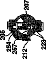
Figure 23 is the rear end partial, exploded perspective view of the code brake bars lock core column assembly shown in Figure 22, shows the situation that does not have shell and removed the side lever pedestal;
Figure 24 is the decomposition diagram of the side lever pedestal shown in Figure 23;
Figure 25 A is the phantom drawing of the brake bars shown in Figure 23, shows to be in not encoding state, and wherein the key joint element separates with the side lever joint element;
Figure 25 B is the phantom drawing of the brake bars shown in Figure 25 A, shows the key with insertion, the part that moves to key code in the brake bars, and the key joint element that separates with the side lever joint element;
Figure 25 C is the phantom drawing of the brake bars shown in Figure 25 A, illustrates to have the brake bars (that is, the key joint element engages with the side lever joint element) that is encoded, and has wherein removed key;
Figure 25 D is the viewgraph of cross-section of the lock shown in Figure 22, shows when being locked in coding and lock-out state each relative positions of following time;
Figure 26 is the front perspective view according to the code brake bars lock set of seventh embodiment of the invention;
Figure 27 is the front perspective view of the lock barrel shown in Figure 26, show the state that takes out from shell and wherein side lever be extended;
Figure 28 is the schematic partial front perspective view of the lock barrel shown in Figure 27, shows the part of lock barrel is removed to show side lever and side lever engage brake bolt element;
Figure 29 is the front perspective view of brake bars shown in Figure 28 and side lever, shows the state that takes out from lock barrel;
Figure 30 is the front perspective view similar to Figure 29, shows the several brake barses that are removed;
Figure 31 A is the phantom drawing of the side lever engage brake bolt element shown in Figure 27 and 28, shows the zigzag opening of side lever joint element;
Figure 31 B is the phantom drawing of the side lever engage brake bolt element shown in Figure 31 A, shows opposition side;
Figure 32 is the phantom drawing of the key engage brake bolt element shown in Figure 29;
Figure 33 is the side lever that shifts out from the lock barrel according to the code brake bars lock set of eighth embodiment of the invention and the phantom drawing of brake bars;
Figure 34 A is the phantom drawing of the brake bars shown in Figure 33, illustrates to have to be in the not brake bars of coding site;
Figure 34 B is the phantom drawing of the brake bars shown in Figure 34 A, illustrates to have the brake bars that is in the position in the cataloged procedure and the projection of brake bars is alignd with the depression of brake bars;
Figure 34 C is the phantom drawing of the brake bars shown in Figure 34 A, illustrates to have the brake bars that is in coding site;
Figure 35 A is the phantom drawing of the code brake bars lock set of the optional embodiment according to the present invention;
Figure 35 B is the phantom drawing of an embodiment of key that is used for the code brake bars lock set of Figure 35 A;
Figure 35 C is the lateral view of brake bars that is used for the code brake bars lock set of Figure 35 A;
Figure 35 D is the rear elevation of side lever that is used for the code brake bars lock set of Figure 35 A, and this side lever is shown as and is in before the coding;
Figure 35 E is the phantom drawing of the code brake bars lock set among Figure 35 A, and but it is in and key is inserted the state that code brake bars lock set also is not encoded;
Figure 35 F is the rear elevation of the side lever of Figure 35 D, and but it is depicted as to be in and key is inserted the state that code brake bars lock set also is not encoded;
Figure 35 G is the lateral view of the code brake bars lock set of Figure 35 A, and the wedge of wherein encoding was in elevated position before coding;
Figure 35 H is the front perspective view of the code brake bars lock set of Figure 35 A, and the wedge of wherein encoding was in retracted position before coding;
Figure 35 I is the lateral view of the code brake bars lock set of Figure 35 A, and the wedge of wherein encoding is in retracted position after coding;
Figure 35 J is the rear elevation that is in the side lever of coding Figure 35 A afterwards;
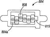
Figure 36 A is the phantom drawing of the braking latch assembly of can encoding again of optional embodiment according to the present invention;
Figure 36 B is the exploded view of the braking latch assembly of can encoding again shown in Figure 36 A;
Figure 36 C is another exploded view of the braking latch assembly of can encoding again shown in Figure 36 A;
Figure 36 D is the cross section of the braking latch assembly of can encoding again shown in Figure 36 A;
Figure 36 E is another cross section of the braking latch assembly of can encoding again shown in Figure 36 A;
Figure 36 F is the front elevation drawing of the braking latch assembly of can encoding again shown in Figure 36 A;
Figure 36 G is the bottom view of the part of the braking latch assembly of can encoding again shown in Figure 36 A;
Figure 36 H is the lateral view of the part of the braking latch assembly of can encoding again shown in Figure 36 A;
Figure 36 I is the phantom drawing of the part of the braking latch assembly of can encoding again shown in Figure 36 A.
The specific embodiment
According to an embodiment of lock set of the present invention shown in Fig. 1-13.At first with reference to figure 1-5, the lock set that illustrates (with 29 indications integrally) comprises shell 14, lock barrel 30 and brake bars 23, this lock barrel is positioned in the shell 14 and optionally with respect to shell 14 rotations, and brake bars is coupled and is used for can moving pivotally in lock barrel 30.By illustrated mode, the group 10 of the lock ﹠ key of this character is inserted key 26 (seeing Figure 12) by the key 1 that will suitably encode in the end of lock barrel 30 and is operated.Along with key 1 enters in the lock barrel 30, the coded surface of key 1 engages the brake bars 23 that can pivot, and causes the part of each brake bars 23 to pivot.In other embodiment, key 1 enters lock barrel 30 causes each brake bars 30 integrally to pivot.As here using, term " brake bars can pivot " (with its different form) is meant pivotable single-piece brake bars 23 and two-piece type or multi-piece type brake bars 23 in lock set 29, and this two-piece type or multi-piece type brake bars have pivotable one or more members in lock set 29.
When the key 1 of suitable coding was fully inserted in the lock set 29, the surface of brake bars 23 by key 1 moved to brake bars 23 and is retracted in position (Fig. 4) in the lock barrel 30 from the relevant position that one or more brake barses 23 extend lock barrel 30 (Fig. 3).In certain embodiments, in case insert key 1, then all brake bars 23 moves to retracted position from extended position.Then, can screw key 1 and lock barrel 30, the mechanism that is connected with lock set 29 with release.In this position, lock set 29 is unlocked.Then, key 1 can be rotated back to initial position, and it can be removed (under the situation of not carrying out such rotation, just can remove perhaps in certain embodiments).In this position, because lock barrel 30 can not rotate in shell 14, therefore, lock set 29 is in the lock state.By removing key 1, can pivot back their initial position of brake bars 23, at this initial position, at least one brake bars 23 14 extends from lock barrel 30 towards shell.
With reference to Fig. 1,2 and 5 that embodiment is shown, the lock set 29 of this embodiment has shell 14.In certain embodiments, shell 14 is the interfaces between lock set 29 and just blocked element, assembly or the device.The external surface 39 of shell 14 and 40 can be constructed to lock set 29 be matched element, assembly and the device of various application and lock set 29 is kept within it, and the element of various application, assembly and device are used including, but not limited to car door, plaque lid, control stick, instrument panel, automobile trunk, glove box and other vehicle.
In some embodiments of the invention, shell 14 also supports various other the workpieces of lock set 29.For example, as shown in Figure 2, shell 14 can have the diameter of variation along its length, and lock barrel 30 axially is contained in this shell.The inner surface of lock barrel 30 can have the ledge surface (34,35) that goes out as shown, and inner surface can change in any other mode, perhaps can have constant substantially diameter.The shell 14 of some embodiment has two inner axial grooves 36,37, and under the lock-out state of lock set 29, this inside axial groove can be admitted the part 52,63 (seeing Fig. 2 and Figure 11 A-E) from lock barrel 30 extensions of the brake bars 23 that can pivot.When the key of mistake was inserted in the lock barrel 30, two inner axial grooves 36,37 also can be admitted the part 32,33 that can extend from lock barrel 30 of the brake bars 30 that can pivot.As mentioned above, when brake bars 23 is moved with when lock barrel 30 extends to shell 14, brake bars 23 rotations of opposing lock barrel 30 in shell 14.For this purpose, the groove 36,37 of any amount or other depression can be positioned in any part of lock barrel inside, thereby admit brake bars 23.Because the brake bars 23 in the embodiment shown in Fig. 1-13 can pivot along two different directions round axis, as below being elaborated, what therefore adopt in this embodiment is to have minimum two grooves in the shell 14.In certain embodiments, can pivot brake bars 23 and one or more fexible bias pressure member (for example spring 12) are admitted and supported to lock barrel 30, and described fexible bias pressure member is used for along 14 part or all the pivoted brake barses 23 of direction bias voltage from lock barrel 30 towards shell.In this, lock barrel 30 can have opening 24, when brake bars end 52,63 is pivoted to extended position (latched position), as shown in Figure 3, brake bars end 52,63 extends through this opening 24, and when using wrong key, brake bars end 52,63 can extend through this opening 24.Alternatively, lock barrel 30 can have any other shape, and this shape allows brake bars end 52,63 to extend towards shell 14, to engage within it or to be received within depression, groove or other openings in the shell 14.At unlocked position as shown in Figure 4, brake bars end 52 and 63 is withdrawn in the circumference of lock barrel 30, rotates in shell 14 to allow lock barrel 30.
Shown in Fig. 1 and 3-5, lock barrel 30 can be constructed to two parts 11,13, these two parts by rivet, welding, screw, bolt, be fastened and connected, bond or adhere connect material, band, clip, pin is connected with opening or any other mode links together.The substitute is, lock barrel 30 can be an element that utilizes any traditional approach (for example moulding, machining, casting or the like) to make, perhaps can be formed by three or more parts, any mode that described three or more parts are described by two the lock barrel parts 11,13 shown in the above-mentioned reference links together.
In certain embodiments, lock barrel 30 has the louver body (not shown), and this louver body covers at least in part or covers key 26.Shutter can be close on the end that key 26 is installed in lock barrel 30.In addition, output mechanism can be connected to the opposite end of lock barrel 30, is used for power is delivered to the one or more elements that are connected in lock set 29 from lock barrel 30.Export structure can be taked multiple different form, includes but not limited to be installed to control lever (lever), driving shaft, connection, cam or other elements of lock set 29.
As described above, the brake bars 23 that can pivot can be coupled to lock barrel 30, to rotate with respect to lock barrel 30.Brake bars 23 can be installed by any way pivotly.Yet in the embodiment shown in fig. 3, brake bars 23 is pivotably mounted on the pivot 8, and it is attached to lock barrel 30.
Shown in the embodiment as shown in fig. 11, when key 1 was inserted lock barrel 30, brake bars 23 can engage key 1, and when key 1 not being inserted lock barrel 30, can be in conjunction with shell 14.Brake bars 23 can be by so any material, and this material is enough durable and enough firmly with the attempt of bearing any picking lock and undelegated powerful rotation lock stem and can resist wearing and tearing with the boundary of key 1.The size of brake bars 23 can be set to engage key in the key edge of the various degree of depth.Therefore, by using a plurality of brake barses 23, lock 29 key 1 releases that can only suitably be encoded with different key deep engagement keys 1.In certain embodiments, the embodiment shown in Fig. 1-13 for example, brake bars is positioned on the opposite side of key 1, engages thereby two coding edges 49,50 of key 1 are braked bolt 23.In this embodiment, brake bars 23 can be arranged by any way, and can be arranged in the lock set 29 with alternate mode in some cases.Still in this embodiment, brake bars 23 can be positioned as in response to the insertion of key 1 or shift out and pivot in opposite substantially direction.
Although each brake bars 23 of the present invention can be a discrete component, brake bars limits by two or more elements in certain embodiments.For example, brake bars 23 can be the two-piece type brake bars, shown in Fig. 5-9 and Figure 11 A-E.As shown, each pivotable two-piece type brake bars combination 23 by shell joint element 4 or 5 and key joint element 6 or 7 constitute.In certain embodiments, under the locking mode of lock set 29, shell joint element 4,5 is removable with splice enclosure 14 (thereby preventing lock barrel 30 rotations), and separates (thereby allowing lock barrel 30 with respect to shell 14 rotations) under unlock mode with shell 14.In addition, key joint element 6 and 7 can engage the coded surface 49 and 50 of key 1.In other embodiment, key joint element 6 and 7 can be positioned as on key 1 one sides one of being in only splicing encoded surperficial 49,50, as mentioned above.Whatsoever under the situation, each key joint element 6,7 all can have one or more surperficial 56, and when key 1 inserted in the lock set 29, this surface was contacted by one or more coded surfaces of key 1.This contact causes key joint element 6,7 to move with respect to shell joint element 4,5, and the two-piece type brake bars that is used to encode makes up 23 purpose, will be described in more detail below.
In certain embodiments, when lock set 29 was in not encoding state, shell joint element 4 and 5 was independent of key joint element 6 and 7 pivotally.When lock set 29 was in encoding state, this shell joint element 4 and 5 was independent of key joint element 6 and 7 no longer pivotally.
Brake bars 23 (and under the situation of multi-piece type brake bars, it is the element of brake bars 23) can pivot in lock barrel 30 with multitude of different ways.For example, in an embodiment as example, shell joint element 4,5 can pivot around pivot 8.Shell joint element 4,5 can pivot around pivot 8 by any way, for example by pivot 8 being received in the opening 51 in the shell joint element 4,5, shown in Fig. 5 and Figure 11 A-E.If desired, the position of pivot 8 between the end 59,60 of pivot 8 can have than major diameter part 58, to be provided for the position of extra support pivot 8 and brake bars 23.
Although shell joint element 4,5 can be taked aforesaid Any shape, promptly this shape can move it and enter and the engaging of disengaging and shell 14, but in certain embodiments, shell joint element 4,5 has opening within it, and key 1 can be admitted by this opening.The element 4 and 5 of this embodiment also has at least one part 52,63 (perhaps having two parts 52,63 in other embodiments), and this part is splice enclosure 14 under the lock-out state of aforesaid lock set 29.
In those embodiment of use multi-piece type brake bars 23 of the present invention, the member of brake bars 23 can be for relative to each other movably, and can be engaged with each other at different relative position places.This joint can produce with different ways.For example, shown in the embodiment as example in, each shell joint element 4,5 can be by engaging corresponding key joint element 6,7 at the tooth that is meshing with each other of two elements 4,5 and 6,7 on both.In this juncture, shell joint closes at least one projection on the element 4,5 or caves in and 54 can be respectively engages with at least one depressions or protrusions 57 on key joint element 6,7 outside.Yet in other embodiment, shell joint element 4,5 or key joint element 6,7 have a plurality of depressions or protrusions, so that element 4,5 is engaged with each other at two different relative position places with 6,7 at least.In other embodiment, two elements 4,5 and 6,7 also has a plurality of depressions or protrusions, so that a plurality of relative bondings position of element 4,5,6,7 to be provided.
Although projection that is bonded with each other and depression 54,57 can be used to splice enclosure joint element 4,5 and key joint element 6,7, it should be noted that the element of other types can replace being used for this purpose.The mode by example only, shell joint element 4,5 can have one or more magnets thereon, this magnet can attract the one or more magnets on key joint element 6,7, so that shell joint element 4,5 is remained on the appropriate location with respect to key joint element 4,5,6,7.As another example, shell joint element 4,5 can have one or more surfaces, this surface by the one or more surface of key joint element 6,7 utilize the enough big system of defeating against, so that shell joint element 4,5 is concerned with respect to the position that key joint element 6,7 remains on expectation.Can also use other elements and the feature of shell and key joint element 4,5,6,7, shell joint element 4,5 is remained on the position relation of expectation with respect to key joint element 6,7.In other embodiment, two elements 4,5 and 6,7 can also by be fastened, frictional fit or the like keeps together.
(for example embodiment shown in Fig. 1-13) in some embodiments of the invention, shell and key joint element 4,5,6,7 are flat substantially shape.In other embodiment, shell and key joint element 4,5,6,7 have other any desired shapes.Yet, can use the element of flat pattern substantially, the purpose that is used to save the space.
On any part that the projection of shell and key joint element 4,5,6,7 and 54,57 these elements of permission that can be positioned at shell and key joint element 4,5,6,7 that cave in are engaged with each other, below with more detailed description.Yet, the inventor finds, when the part of the part of shell joint element 4,5 and/or key joint element 6,7 is positioned in the plane different with the remainder of shell joint element 4,5 and key binding member 6,7 respectively, space in lock set 29 is by better utilization, and improved the performance of lock set 29.More specifically, expectation is in certain embodiments, the joint element of shell and/or key joint element 4,5,6,7 or feature (for example, projection or cave in 54,57) are positioned in the outside with respect to the plane of the remainder of similar elements 4,5,6,7.For example, shown in the embodiment shown in Fig. 5-9 and 11, the projection of each shell joint element 4,5 and cave in and 54 be positioned in being in of shell joint element 4,5 with respect on the part outside the plane of shell joint element 4,5 remainders.If desired, key joint element 6,7 can also or have biasing depression and projection 57 with replacing.In certain embodiments, shell joint element 4,5 or key joint element 6,7 (but not being the both) have this biased engagement feature or structure.
Have among those embodiment of brake bars of two or more elements (as mentioned above) in use of the present invention, the brake bars element that moving into the relation of being engaged with each other can be in repeatedly between the operating period and keep this relation afterwards of lock set.This can realize by the different ways that depends on the engaged mode of brake bars element at least in part.For example, if the magnet group can remain on the brake bars element relation that is engaged with each other, then the magnet group can be enough to keep this relation.Similarly, keep the relation that is engaged with each other, then frictional fit or be fastened and be enough to keep this relation if use frictional fit or be fastened.In other embodiment, the engagement relationship between the brake bars element keeps by one (or a plurality of) point that change brake bars elements pivot is centered on.Key joint element 6,7 in the embodiment shown in Fig. 1-13 provides the example of this element control.
Particularly, shown in the embodiment shown in Fig. 5,7,9 and 11, pivot 8 can pass the opening 55 in the key joint element 6,7, and this opening is configured as at two diverse locations and admits pivot 8.Key joint element 6,7 can pivot around pivot 8, and can move to another position from a position with respect to pivot 8.Go out as shown, opening 55 is shaped as pivot 8 is remained in two diverse locations at least one, thereby key joint element 6,7 can move with respect to pivot 8, and can be maintained at the position that key joint element 6,7 engages with shell joint element 4,5.For example, in the embodiment shown in Fig. 1-13, key joint element 4,5 has the two positions opening 55 of the hourglass shape of being configured as.The hourglass shape of these openings 55 allows pivot 8 to move (perhaps opening 55 moves with respect to pivot 8) in opening 55, and " fastening " enters the position with respect to pivot 8, key joint element 6,7 engages with shell joint element 4,5 in described position, as mentioned above.In this, opening 55 can be deformable, to produce snap action between two position 55a, 55b of the key joint element on the supporter 86,7.In certain embodiments, the deformability in hole can utilize one or more seams, otch, hole or release opening 65 near the pivot opening 55, the relative thin by pivot opening 55 is provided wall or flexible wall, realize by between the pivot aperture position, using one or more projections or the like.
In certain embodiments, key joint element 6 and 7 is placed on the not coding site on the pivot 8 between the erecting stage of lock 29.For example, in the illustrated embodiment, pivot 8 passes the inside position 55a of two positions opening 55, the projection of normal key joint element 6,7/depression 57 (or a plurality of) thus, thus they separate with the coupling projection/depression (or a plurality of) of shell joint element 4,5.Tumbler assemblies 23 can be maintained on the pivot 8 by screw thread, weld seam, clip, lasso or other likes of pushing on packing ring 3, the nut at any end or 59,60 places, two ends of pivot 8.Yet, in some optional embodiment, (for example wherein not needing to move among the embodiment that carries out the brake bars coding) by element with respect to pivot 8, pivot 8 can form the part of an element of two-piece type brake bars 23.
Although the brake bars 23 of lock set 29, pivot 8 and other elements can assemble by any way, but in certain embodiments, uncoded brake bars elements combination (that is, shell joint element 4 that cooperates with key joint element 7 or the shell joint element 5 that cooperates with key joint element 6) can be assemblied on the pivot 8 and as a unit sub-component to be inserted in the lock barrel 30.
With reference now to by the embodiment of Figure 11 A-11E shown in the by way of example only,, cataloged procedure of the present invention will be described.In the embodiment shown in this, the cataloged procedure of lock set 29 is from the insertion of key 1, as shown in Figure 11 B.Along with key 1 enters lock barrel 30, key joint element 6 and 7 be pivoted to small part by the determined scope of coding depth on surfaces of keys 49,50.In case key 1 fully inserts, key joint element 6 and 7 places the coded surface 49,50 of key against ground.
As shown in the order shown in Figure 11 B-11D, by in response to the rotation of key 1 with respect to shell 14 rotation lock stems 30, lock 29 is encoded at key 1.Along with lock barrel 30 rotates, key joint element 6 and 7 on pivot 8 from inside pivot hole position 55a move to outside pivot hole position 55b (in conjunction with Fig. 7 and 9 and referring to Figure 11 C and 11D).Should move and can cause by different ways, for example by key joint element 6,7 against the cam of the inner surface of shell 14, apply one or more springs of power or the like directly or indirectly to key joint element 6,7 by at least one position of rotation place at lock barrel 30.
Key joint element 6 and 7 can cause the projection on key joint element 6 and 7 and/or 57 (or a plurality of) of caving in, the depression of the correspondence on the splice enclosure joint element 4 and 5 and/or projection 54 (or a plurality of) moving from inside position 55a to external position 55b on the pivot 8.This joint has produced the brake bars combination 23 of the specific notch depth that is encoded to key 1.Therefore, under encoding state, shell joint element 4,5 and key joint element 6,7 can pivot together around pivot 8.Shown in Figure 11 E, in case key 1 is moved out of, at least one spring 12 (see figure 5) can be biased into one or more brake barses 23 and the engaging of shell 14, and prevents that thus lock barrel 30 is with respect to shell 14 rotations.
In case brake bars 23 is encoded, then brake bars 23 can remain on their encoding state in one or more modes.For example, in the two-piece type brake bars embodiment shown in Fig. 1-13, key joint element 6,7 is retained as with shell joint element 4,5 has the encoding relation that it engages, and the encoding relation of described joint is partly kept by the relation between above-mentioned pivot 8 and the two positions opening 55.
Fig. 1,5 and 10-11 in the another kind of mode that brake bars 23 is remained on after the coding their encoding state has been shown.Particularly, lock set 29 in the illustrated embodiment has brake bars travel mechanism 31, be used for key engage brake bolt element 6 and 7 in lock barrel 30 never coding site move to coding site.Brake bars travel mechanism 31 is connected to shell 14 or forms as one with shell 14, and can be suitable for comprising removable supporter 15, brake bars movable plate/bar 17, brake bars movable plate supporter 16, one or more spring 18 and cover 19.This lid 19 can form as one with shell 14, and utilize one or more pins 20,21 (seeing Fig. 1,5 and 10), screw, rivet, clip and other traditional fasteners in other embodiments, utilize viscosity or bonding connection material, shell 14 or the like is connected with it by being fastened.If desired, shell 14 can be provided with one or more elements or feature, so that brake bars travel mechanism 31 is connected with it, and helps moving of brake bars travel mechanism 31, thus bias voltage brake bars 23, as below illustrating.For example, in the illustrated embodiment, shell 14 has bead (lug) 41, raceway groove 42 and opening 43, this bead is used to install brake bars travel mechanism 31 (certainly replace ground and use other fastener opening, projection, clip socket or other elements), this raceway groove is used for supporting and the removable supporter 15 that leads, brake bars movable plate/bar 17 can extend through this opening 43 or otherwise be received within this opening 43, so that brake bars 23 is biased in the shell 14.
Brake bars travel mechanism 31 can (brake bars movable plate/bar 17 be biased applying power on the brake bars in shell 14 23, and mobile brake bars 23, as mentioned above) by being activated with respect to shell 14 rotation lock stems 30.For example, in the illustrated embodiment, when lock barrel 30 was rotated during cataloged procedure, the surface 61 on the removable supporter 15 (seeing Fig. 1 and 10) was by the protruding top of part of lock barrel 30.More specifically, when lock barrel during cataloged procedure 30 is rotated, the removable supporter 15 of the protruding top of the cam face 66 on the back of lock barrel 30 (seeing Fig. 3 and 4) brake bars travel mechanism 31.Refer again to Fig. 1 and 10, the effect of cam-follower is played on the surface 61 of removable supporter 15 thus.As shown in Figure 10A and 10B, because follower 61 relies on (riding) on cam face 66, therefore removable supporter 15 moves with respect to the remainder of brake bars travel mechanism 31, cause brake bars movable plate supporter 16 to unclamp thus, and allow resiliently biased brake bars movable plate/bar 17 radially to move inward towards lock barrel 30 from removable supporter 15.Shown in Figure 11 C and 11D, should moving of brake bars movable plate/bar 17 causes brake bars movable plate contact key engage brake bolt element 6,7, and cause key engage brake bolt element 6,7 never encoding state move to encoding state, describe in detail as top.
Although above-mentioned brake bars travel mechanism 31 is a kind of modes of 23 pairs of lock sets of mobile brake bars, 29 codings, it should be understood that brake bars travel mechanism 31 can adopt multiple other forms that can carry out this identical function.The mode by example only, in case key 1 is inserted lock barrel 30, then the brake bars travel mechanism such as above-mentioned brake bars travel mechanism can be triggered, with brake bars movable plate/bar 17 towards brake bars 23 bias voltages.Particularly, in case key 1 is inserted lock barrel 30, then key 1 can contact and move removable supporter 15 (perhaps similar elements or structure) directly or indirectly.Then, lock barrel 30 can align biased brake bars movable plate/bar 17 with respect to the rotation of shell 14 with shell aperture 43, enters brake bars opening 43 to allow brake bars movable plate 43, and bias voltage brake bars 23, as mentioned above.
As another example, can brake bars movable plate supporter 16 be removed by the user and activate brake bars movable plate/bar 17, wherein this brake bars movable plate supporter 16 is that brake bars movable plate/bar 17 is remained on (in this case, not needing removable supporter 15 or element that is equal to or structure) with respect to the retracted position of brake bars 23.In this, brake bars movable plate supporter 16 can be taked to be removed or be otherwise released to activate the multiple different form of brake bars movable plate/bar 17.Can also use other structure, in case so that in case when inserting key 1 in the lock barrel 30 or lock barrel 30 during with respect to shell 14 rotations, then bias voltage brake bars movable plate/bar 17 or other elements make it abut against brake bars 23 in the shell 14.In these optional mechanisms each falls in the spirit and scope of the present invention.
In some embodiments of the invention, desirably be before utilizing key 1 coding lock set 29, to keep the position of rotation of lock barrel 30 with respect to shell 14.For example, can use element or device to prevent that lock barrel 30 from rotating with respect to shell 14 during transportation or operable lock assembly.An example of this element has been shown in Fig. 1,3-5,12 and 13.In the illustrated embodiment, transportation brake bars 9 keeps the position of lock barrel 30 with respect to shell 14, thus, has kept the orientation of brake bars combination before lock set 29 is encoded.In certain embodiments, these transportation brake barses 9 or similar structure (as describing in detail in other embodiments) can also prevent that cataloged procedure from beginning prematurely.For example, in the illustrated embodiment, the transportation brake bars is positioned and is orientated and prevents lock barrel 30 rotation and lock is encoded, and is fully inserted into up to key 1.
With reference to figure 5, transportation brake bars 9 can form " E " shape with three foot section 46,47,48.Best shown in Figure 12 and 13, uncoded lock set 29 can lock barrel 30 from middle position (vertical line of key) rotation a certain amount of (for example, be 21 in the illustrated embodiment, but littler or bigger rotation amount also is possible) situation under be assembled and install, and by the transportation brake bars 9 be fixed on this position.With reference to figure 12A, lock barrel 30 is in coding site not and the depression, groove, seam or other the openings 25 that extend in the shell 14 by the end 38 with the foot section 38 of a transportation brake bars are maintained at this position.Although transportation brake bars 9 can by be fastened or suppress the lock barrel 30 that is connected, by gently frictionally engaging within the opening 25 or otherwise being maintained at this position, transport brake bars 9 and still can utilize at least one spring 22 to be biased in this position.
Continue with reference to the embodiment shown in figure 12B and the 13B, the insertion of key 1 can form moving of transportation brake bars 9, with the 25 withdrawal transportation brake barses 9 of the opening in shell 14.More specifically, when selected key 1 is fully inserted lock barrel 30 during cataloged procedure, the surface of key 1 (for example, end at key 1) can contact the foot section 46 of transportation brake bars 9, overcome the biasing force of transportation brake bars spring 22 thus and protruding top transportation brake bars 9 away from shell aperture 25.After this, allow lock barrel 30 rotations.
What will be understood by those skilled in the art that is that transportation brake bars 9 can be taked can be in the multiple different shape that plays retractile action during the cataloged procedure when in a single day key 1 inserts.The shape of transportation brake bars 9 depends on the shape and/or the position of transportation brake bars 9 on lock barrel 30 of shape, shell 14 and the shell aperture 25 of lock barrel 30 at least in part.Other transportation brake bars can be C shape or L shaped, can be shaped as and 23 similar shapes of brake bars in the illustrated embodiment, can be shaped or the like in any traditional mode.In addition, it should be noted that if desired, transportation brake bars 23 can be by the user manually from shell aperture 25 withdrawal, and, in certain embodiments or even can in lock set 29, remove.
For illustrated purpose, Figure 11 A-11E shows the encoding operation of carrying out on the lock set 29 in illustrated embodiment of the present invention.Assembling and uncoded lock 29 can be installed on the member (not shown) to be locked or in, wherein transport brake bars and extend in its transporting position, brake bars element 4,5,6,7 is in their position that is not encoded, and there is not key in the key 26 in the lock barrel 30, shown in Figure 11 A.Because brake bars end 32 contacts the inner surface of shell 14 and can not enter the axial groove of shell owing to the transport orientation of lock barrel 30 with 52, so shell engage brake bolt element 4,5 is limited in the border of lock barrel 30 when transporting position.When key 1 inserts lock barrel 30, because the coded surface 49 contact brake bars surfaces 56 of key 1, so key engage brake bolt element 6,7 is round pivot 8 pivots (seeing Figure 11 B).
Continue the embodiment shown in the reference, in case key 1 is fully inserted in the lock barrel 30, then transports brake bars 9 and can separate (seeing shown in Figure 12 and 13), thereby allow lock barrel 30 with respect to shell 14 rotations from shell 14.Then, key is rotated, and so that lock barrel 30 is rotated to the centre position, shown in Figure 11 C, this causes brake bars travel mechanism 31 to activate (that is take-off the brake bolt movable plate/bar 17).Brake bars movable plate/bar 17 is biased towards the center of lock barrel 30 thus, and this causes key joint element 6,7 to move, to engage corresponding shell joint element 4,5.Thus, finish cataloged procedure, shown in Figure 11 D, and key 1 shifted out in lock barrel 30.When key 1 shifts out in lock barrel 30, brake bars 23 can be biased round pivot 8, cause the border of shell engage brake bolt componentry 32,33,52,63 extend through lock barrels 30, enter the axial groove 36 of shell 14, prevent that thus lock barrel 30 is with respect to shell 14 rotations (seeing Figure 11 E).In the lock-out state of the lock set 29 that forms, shell engage brake bolt componentry 32,33,52,63 rotates to prevent lock barrel, as shown in Figure 3 in the enclosure with the opposite side on mode extend through lock barrel 30 borders that replace substantially.
Have in the some embodiments of the present invention of two or more brake bars elements at brake bars, code lock set 29 can be encoded again.Coding can be carried out with different ways again, and every kind of mode allows the element of one or more brake barses 23 to separate to realize coding again.For example, in the embodiment shown in Fig. 1-13, shell 14 can have one or more openings 44, is used for key joint element 6,7 is entered from the instrument that shell joint element 4,5 pushes away allowing.More specifically,, the key 1 of encoding for lock set 29 is inserted into lock barrel 30, and lock barrel 30 is rotated to its original transporting position for encoded lock set 29 is encoded to different key codes again with reference to figure 2.Then, instrument is inserted in each notch 44 in the shell 14, so that key engage brake bolt element 6,7 is moved back to its initial uncoded position, in this position, they are from 4,5 withdrawals of shell engage brake bolt element.After finishing this, key 1 is contracted, and can reset brake bars travel mechanism 31 (if it has been used).For example, in the embodiment shown in Fig. 1-13, brake bars movable plate/bar 17 is from the state withdrawal (if desired, removing pin 20,21, lid 19 and spring 18) of its extension, and removable supporter 15 is returned to its transporting position.Then, another key that will have new coding inserts in the lock barrel 30, with the repeated encoding process.
In other embodiment, brake bars travel mechanism 31 can partially or fully be removed or opening, to allow the user near key engage brake bolt element 6,7 (and/or shell joint element 4,5), to control key engage brake bolt element 6,7.In other embodiment, pivot 8 can be approaching by the user, and can be moved, thereby mobile brake bars is to realize coding again.Only by the mode of example, the pivot 8 in the embodiment shown in Fig. 1-13 can be moved to separate key joint element 6,7 from shell joint element 4,5.In this case, then, new key can be inserted, and pivot 8 is turned back to its home position, be used to carry out remaining encoding operation.Other modes of in lock set 29 of the present invention key being encoded again also are possible, and each of these modes falls in the spirit and scope of the present invention.
Another embodiment of the brake bars lock set that can pivot has been shown among Figure 14 A-14E, and with 129 totally expressions.Similar to the brake bars lock set 29 in the embodiment shown in Fig. 1-13, the embodiment shown in Figure 14 A-14E has used the pivoted brake bars 123 in lock barrel 130, and this brake bars is optionally rotatable with respect to shell 114.Also similar to the embodiment shown in Fig. 1-13, this embodiment has used the pivoted brake bars 23 of code, and each is to be limited by movably a plurality of elements relative to each other.Embodiment shown in Figure 14 A-14E has used the brake bars 23 that all has two elements.First element is a key joint element 6, and this key joint element can engage the coded surface 149 of key 101.Second element can be a shell joint element 104, and this shell joint element is the shell joint latched position splice enclosure 114 releasably of closing element 104 outside.Before coding, key joint element 106 can irrespectively can pivot with shell joint element 104.Particularly, key joint element 106 can be pivotably connected to the rod follower 170 in the lock barrel 130.If desired, key engage brake bolt element 106 can also be by spring 112 bias voltages.In addition, shell joint element 104 can be positioned in the lock barrel 130, and is led by lock barrel 130 and support.
Key engage brake bolt element 106 can have at least one projection and/or cave in 157, is used for optionally respectively engaging with one or more depressions and/or projection 154 on the shell joint element 104, with splice enclosure joint element 104 under the state of coding.The projection of key engage brake bolt element 106 and/or cave in 157 can be positioned on the key engage brake bolt element 106 Anywhere, but in some other embodiment, on the end relative that they are positioned in key engage brake bolt element 106 with pivot 108.Although can having, the lock barrel 130 of lock set 129 is positioned as the brake bars 123 that only contact is in the coded surface on key 101 1 sides, but the lock barrel 130 among some embodiment have be positioned as the coded surface on contact key 101 opposite sides brake bars 123 (for example, have key engage brake bolt element 106 alternately, it pivots in opposite direction when being positioned in and contacting with key 101).As shown in the embodiment shown in Figure 14 E, shell joint element 104 can extend in groove, depression or other the opening of shell 114, thus splice enclosure 114 under the locking mode of lock set 129.For the brake bars 123 with two or more elements, at least one brake bars element is shaped as splice enclosure 114 by this way.For example, continue with reference to figure 14A-14E, the part of each shell engage brake bolt element 104 can be shaped as in depression, groove or other openings that is received within shell 114.
Can under the not encoding condition shown in Figure 14 A and 14B, be assembled at the lock set among the embodiment shown in Figure 14 A-14E 129, wherein shell joint element 104 is included in the lock barrel 130 by shell 114.Thus, follower 170 is received within depression, groove and other openings 171 in the inwall of shell 114.
In order to be the lock set 129 setting codings shown in Figure 14 A-14E, key 101 is inserted in the lock barrel 130, and key joint element 106 is with respect to coded surface 149,150 pivots of key 101, as shown in Figure 14 B.In case key 101 is fully inserted into, in the projection on the key joint element 106 and/or cave in and 157 can close the corresponding projection on the element 104 with shell joint outside and/or cave in and 154 align.Shown in Figure 14 C and 14D, key 101 is in company with rotation in the lock barrel 130 shell together 114 then, and this causes follower 170 to be advanced in the lock barrel 130 by the cam face radial drive on the shell 114.For the key notch depth of the correspondence of each the brake bars position in the lock barrel 130, follower 170 cause the projection on the key joint element 106 and/or cave in 157 become with shell joint element 104 on corresponding depression and/or projection 154 engage.In the embodiment shown in Figure 14 A-14E, then about 180 of lock barrel 130 rotations are arrived middle lock-out state, but this state can be positioned at littler or bigger angle in other embodiments.In certain embodiments, behind the coding, the available angular range of lock barrel rotation can be+60.Yet other rotating range falls in the spirit and scope of the present invention.Therefore, in other embodiments, at least in part according to the position of the shell aperture of admitting brake bars 123 and the shape of brake bars 123, this scope bigger or smaller.Shown in Figure 14 D and 14E, behind coding, follower 170 remains on its radially inner position, and remains on this position by the inwall of shell 114.Therefore, be inserted into lock barrel 130 and when lock barrel 130 was extracted, brake bars combination 123 can keep being bonded to their coding site at key 101.
In order to change the coding of lock set 129, correct key 101 can be used for this lock of release, and allows lock barrel 130 to be rotated to its original coding position.Then, extract key 101 and insert new key.Then, rotation lock stem 130, thus at new key lock set 129 is encoded in the above described manner.
Another embodiment according to code lock of the present invention has been shown among Figure 15-17.As other embodiment shown in Fig. 1-14, this embodiment has also used pivotable two-piece type brake bars 223, is used to the lock set 229 after the assembling that coding is provided.Similar to embodiment before, the embodiment shown in Figure 15-17 has lock barrel 230, shell 214 and the brake bars 223 that can pivot.Yet, with above-mentioned and in Fig. 1-14 embodiment before illustrated different, brake bars 223 can pivot during cataloged procedure, and in lock set 229 normal operating period translations.Each two-piece type brake bars 223 that can pivot can comprise shell joint element 204,205 and key joint element 206,207.In certain embodiments, before coding lock set 229, key joint element 206,207 shell joint outside closes in element 204 and 205 and can pivot.
For the lock set 229 among the embodiment shown in the code pattern 15-17, key 201 is inserted uncoded lock set 229.When key 201 was inserted into, key was through the brake bars 223 in the lock barrel 230.In certain embodiments, for example at the embodiment shown in Figure 15-17, before passing brake bars 223, key 201 also passes seat ring 279 (bezel) or panel.If desired, can between brake bars 223, place gasket element 282, and this gasket element can have and is configured as the opening of therefrom admitting key 201.In case key 201 is inserted into lock set 229, the end of key 201 can contact clutch disc 276.Clutch disc 276 can be to overcome key 201 applied forces and spring-loaded (by one or more springs 278).Spring can be an any type, includes, but are not limited to wind spring, sheet spring, torsionspring etc.For example, the spring 278 in the embodiment shown in Figure 15-17 can be a sheet spring 278, and this sheet spring extends from base portion, and this base portion is received within the shell 214.Can insert lock barrel and clutch disc 276 is mobile backwards by key 201, compress spring 278 thus.
As shown in this embodiment, clutch disc 276 can have opening 277, and this opening initial phase departs from for the end of key 201.Particularly, when opening and key suitably rotate when aliging, opening 277 has the shape of the end that can admit key 201.For example, in the illustrated embodiment, opening 277 is long, and can admit the end of key 201 with certain anglec of rotation of key 201.Can use other shapes of opening 277, and to mate and to admit the end of key 201 with similar mode.Bias between the opening 277 in the end of key 201 and the clutch disc 276 can be corresponding to the rotation amount (below will illustrate in greater detail) of key 201 during cataloged procedure.For example, in the illustrated embodiment, this bias approximately is 130 degree, but bias may be bigger or littler.
Along with key 201 rotates in the lock barrel 230 of the embodiment shown in Figure 15-17, key 201 begins to contact key joint element 206,207, and this causes key joint element 206,207 with respect to 204,205 rotations of shell joint element.In certain embodiments, lock barrel 230 does not together rotate with key 201 in this coding step.Replace, seat ring 279 (if use), key joint element 206,207 and packing ring 282 (if use) can together rotate with key 201.In certain embodiments, can prevent that lock barrel 230 is with respect to shell 214 rotations by shell conjugative component 209.Shell conjugative component 209 can be positioned on the lock barrel 230, and can be used to prevent that lock barrel 230 with respect to shell 214 rotations, is moved up to shell conjugative component 209.In the illustrated embodiment, shell conjugative component 209 is long elements, and is received within groove, seam, depression or other openings in the lock barrel 230, and can axially move within it.
Otch in each key joint element 206,207 rotation amount (this rotation amount has determined the coding of lock set 229) and the key 201 is relevant in the degree of depth of a certain position, and described position is brake bars element 206,207 positions along key 201 places in key 201 is inserted into brake bars 230 time.With reference to figure 17A-17C, because key 201 does not contact key joint element 206,207, up to just contact of rotation in key 201 afterwards, therefore, the notch depth in key 201 is big more, and key joint element 206,207 rotates fewly more.When key joint element 206,207 when shell joint closes in the element 204,205 rotation outside, the projection 57 on key joint element 206,207 afterbodys can be bonded on the depression 254 in the shell joint element 204,205.This joint at least temporarily remains on key joint element 206,207 their coding site with respect to shell joint element 204,205.
Key 201 rotated fully with the end of key 1 with after opening 277 in the clutch disc 276 aligns, the end of key 201 can enter opening 277.In the illustrated embodiment, spring 278 pushes clutch disc 276 towards key 201, to form this joint.Along with clutch member 276 moves towards key 201, clutch member 276 can promote and mobile shell conjugative component 209 with respect to lock barrel 230.In the illustrated embodiment, move away spring 278 in groove, seam, depression or other openings of shell conjugative component 209 in lock barrel 230.Should mobile can cause shell conjugative component 209 to separate, and allow lock barrel 230 thus with respect to shell 214 rotations from lock barrel 230.Should move shoulder or recess, depression, groove, seam or other openings that can also cause seat ring joint element 211 to engage on the seat ring 279, and between seat ring 279 and lock barrel 230, set up mechanical connection thus, thereby utilize key 201 rotation lock stems 230.The orientation of seat ring with respect to lock barrel 230 also established in this connection.Seat ring joint element 211 can be to extend into the one or more spring-loaded pin that engages with seat ring 279, clip, finger etc.Alternatively, seat ring joint element 211 can be such member (as shown in figure 15), and this member is towards the loading spring of seat ring 279 (for example, utilizing one or more springs 213), and be configured as the shape with seat ring 279 coupling, with from seat ring 279 to lock barrel 230 transfer torques.Other shapes of seat ring joint element 211 are possible, and fall in the spirit and scope of the present invention.
Being further rotated of key 201 can make lock barrel 230 rotate through another angle, and this angle can produce cam action between a plurality of clampers 280 that the inner surface and the contiguous brake bars 233 of shell 214 are located.This cam action is similar to the relation between the shell 114 to relation and the follower in the embodiments of the invention shown in Figure 14 A-14E 170 between the shell 14 to the key joint element 6,7 in the embodiments of the invention shown in Fig. 1-13.Especially, clamper 280 can protruding top shell 214, and moves forward into thus in the space that is limited between shell joint element 204,205 and the key joint element 206,207.Clamper is fixed on the appropriate location with key joint element 206,207 with respect to shell joint element 204,205 thus, thus coding brake bars 223.In case key shifts out, spring 212 or other fexible bias pressure member can be biased to brake bars 233 position of their splice enclosure 214.
In the operation of the lock set shown in Figure 15-17 229, key 201 is inserted into lock barrel 230.When inserting key 201, key 201 engages key joint element 206,207, and this causes brake bars combination 223 with respect to lock barrel 230 and shell 214 translations.After inserting key 201, the shell joint element 204,205 of brake bars combination 223 is by indentation lock barrel 230, and this allows lock barrel 230 with key 201 rotations, thus release lock set 229.
Above-mentioned lock set embodiment has all used the one or more brake barses that pivot at certain some place during the process of coding lock set.Other embodiment of the present invention have used during encoding linear or mainly have been linearly moving code brake barses.At the embodiment shown in Figure 18 A-18E is a such embodiment.Similar to the above-mentioned embodiment that illustrates, the lock set 329 shown in Figure 18 A-18E can have one or more brake barses 323 in shell 314, lock barrel 330 and the lock barrel 330.Each brake bars 323 can be limited by two or more elements, and these two or more elements are relative to each other removable, to realize the purpose of coding.For example, in the illustrated embodiment, the brake bars of each code combination 323 comprises key joint element 306,307 and shell joint element 304,305.These elements can be led by lock barrel 330 and support, and go out as shown.
Key joint element 306,307 all can have at least one key composition surface 356 and be used for one or more projections of splice enclosure joint element 304,305 and/or cave in 357.Similarly, shell joint element 304,305 all can have at least one surface, and this at least one surface has the one or more projections that are used for joint key joint element 306,307 during cataloged procedure and/or caves in 354.Although element 304,305,306,307 can have above-mentioned Any shape with reference to the detailed description of the embodiment shown in the figure 1-13, the composition surface of key joint element 306,307 and shell joint element 304,305 can be a bowed shape.In other words, the composition surface of key joint element 306,307 can be to be used for the depressions or protrusions that engage with the projection or the sunk surface of shell joint element 304,305 respectively.An example of this brake bars component shape is shown in Figure 18 A-18E.Arcuate interface face between these brake bars elements can be provided for more encoding and/or is used to improve the bigger composition surface of joint for element 304,305,306,307.In certain embodiments, shell joint element 304,305 is removable, and (for example, each shell joint element 304,305 has such part with splice enclosure 315, when shell joint closed element 304,305 and moves to latched position outside, this part can splice enclosure 315).
Shown in Figure 18 A, lock set 329 can assemble with brake bars combination 323 under uncoded situation.Thus, key joint element 306,307 is removable with respect to shell joint element 304,305.In certain embodiments, key joint element 306,307 by one or more wind springs 312 with respect to shell joint element 304,305 towards a position bias voltage.Although for this purpose, can use one or more springs 312, can use other biasing device, include, but are not limited to the spring of sheet spring, torsion spring and/or other types, magnet group or the like.Before coding, shell joint element 304,305 can be positioned in the border of lock barrel 330 fully or basically, and is remained on wherein by the inwall of shell 314.
In order to be coded in the lock set 329 shown in Figure 18 A-18E, key 301 is inserted lock barrel 330, as shown in Figure 18 B.When inserting key 301, the coded surface of key 301 engages the key composition surface 356 of key joint element 306,307.Key joint element 306,307 is under the effect of key 301 applied forces and reaction is translation and pivot a little.In case key 301 is inserted into, at least one projection on each key joint element 306,307 or cave in and 357 align with at least one depressions or protrusions 354 on corresponding shell joint element 304,305 respectively.In certain embodiments, 357 align with one depressions or protrusions 354 of surpassing on corresponding shell joint element 304,305 respectively in surpassing one projection or caving on each key joint element 306,307.Also in other embodiments, in the one or more projections on the key joint element 304,305 or cave in 357 with one or more projections on corresponding shell joint element 304,305 or cave in and 354 align, but at least one pair of depression and projection are alignd in each brake bars in this embodiment, thereby provide joint between brake bars element 304,306 and 305,307.Mode by example in Figure 18 A-18E shows this layout, the projection 357 that wherein shows key joint element 306,307 contact ground, top with the projection of shell joint element 304,305 top, and the depression top of another projection 357 of key joint element 306,307 and shell joint element 304,305 is to hollowly contacting (still this can be the relation to pushing up of caving in other embodiment).
As mentioned above, key 301 enters in the lock barrel 330 of lock set 329, causes the key composition surface 356 of key joint element 306,307 to move with respect to shell joint element 304,305.The amount of movement of key joint element 306,307 may depend on the key degree of depth at each key joint element 306,307 place at least in part.In certain embodiments, key joint element 306,307 can be positioned in the lock barrel 330, thereby pivots in different directions when key 301 enters.In the embodiment of these and other, some key joint elements 306 can be positioned at lock barrel 330 interior sides with contact key 301, and other key joint element 307 can be positioned in the lock barrel 330 to contact relative sides of key 301.By the brake bars element is arranged in such a way, encode with a side of only using key 301 and to compare, can form more coded sequence.
Although the key joint element 306,307 in Figure 18 A-18E illustrated embodiment is pushed to engage with shell joint element 304,305 with respect to other multi-piece type brake barses in any of the above methods, key joint element 306,307 can engage with shell joint element 304,305 by the cam arrangement between one or more surfaces of follower and shell 314.For example, with reference to figure 18B and 18C, the key 301 of insertion can be rotated, thereby with respect to shell 314 rotation lock stems 330.Along with lock barrel 330 rotations, follower 370 can move on the inner surface of shell 314.Go out as shown, follower 370 can be the shape of bar.Inner surface is preferably shaped to convex top follower 370.In this, follower 370 can be received within before cataloged procedure in groove, depression and other the opening 371 of shell 314.When follower 370 was mobile by this way, follower 370 can force key joint element 306,307 splice enclosure joint elements 304,305.
In certain embodiments, lock barrel 330 is rotated, and is positioned to them up to shell joint element 304,305 with respect to shell 314 and can extends into the position that engages with shell, thereby prevent that lock barrel 330 from rotating with respect to shell.In the embodiment shown in Figure 18 A-18E, for this purpose, lock barrel 330 is rotated about 180 degree, but depends on the initial position relation between shell joint element 304,305 and the shell 314 at least in part, and bigger or littler rotation is possible.
After lock barrel 330 was rotated as top firm explanation, when making key 301 from lock barrel 330 withdrawals owing to follower 370 inside location, brake bars element 323 kept engaging (seeing Figure 18 D).When shifting out key 301, spring 312 can bias voltage brake bars element 323, and this can cause shell joint element 304,305 splice enclosure 314 then, for example engages by the mode that enters one or more grooves, depression or other openings in the shell 314.Do not have in lock barrel 330 under the prerequisite of key 301, this joint prevents that lock barrel 330 is with respect to shell 314 rotations.In the embodiment shown in Figure 18 A-18E, the available scope of lock barrel rotation is approximately+60, but in other embodiments of the invention, littler or bigger lock barrel rotating range is possible.
In order to change the coding of lock set 329, the key 301 that is used for the coding of lock set 329 can be used for release lock set 329, and lock barrel 330 is rotated back to its coding site (for example, seeing Figure 18 A and 18B).Then, key 301 can be extracted, and another can be had the key insertion of different coding.Then, can carry out above-mentioned identical step, to utilize 301 pairs of lock sets of different keys, 329 codings.After rotating back to the scope utilized of lock barrel rotation, have only the new key 301 can release lock set 329.
Another embodiment according to the lock set that pivots of the present invention has been shown among Figure 19-21.Similar to the brake bars lock set 29 in the embodiment shown in Fig. 1-18, the embodiment shown in Figure 19-21 has used the brake bars 423 that can pivot.Yet different with before embodiment is, brake bars 423 is by the outside of general location at lock barrel 430, and can have the part of extending in lock barrel 430.Brake bars 423 in the embodiment shown in Figure 19-21 is positioned in the shell 414, and the position outside lock barrel 430 can pivot.
With reference to Figure 19, the lock set 429 of this embodiment has shell 414, and this shell holds and support the various workpieces of lock set.For example, shell 414 can hold lock barrel 430 and the one or more brake bars 423 that pivots that optionally rotates with respect to shell 414.In the embodiment shown in Figure 19-21, the pivot guider 488 of side lever 484 and mark also is positioned in the shell 414.Side lever 484 is movably with engage brake bolt 430 under lock-out state, and under this lock-out state, lock barrel 430 is limited with respect to shell 414 rotations.Shell 414 can have opening, and lock barrel 430 axially is received in this opening, and perhaps this opening can be shaped as and admits lock barrel 430.Except holding the brake bars 423 that to pivot, shell 414 also holds one or more fexible bias pressure members (for example spring 412), and this fexible bias pressure member is positioned in substantially can pivot part or all of brake bars 423 of direction bias voltage towards lock barrel 430.In certain embodiments, for example at the embodiment shown in Figure 19, biasing member can be inserted in one or more openings of shell 414, and remains on the appropriate location by Shell Plate 414a.In certain embodiments, shell 414 has a plurality of interior grooves 436,437, and the part of the brake bars 423 that can pivot is admitted and held to this interior groove, and the brake bars 423 that is used for pivoting remains on suitable arrangement.
As shown in Figure 19, two or more parts that shell 414 can be constructed to be bonded together by any way for example are connected or the like by rivet, anvil stake or curl (no matter whether being to use the mother metal of housing parts), welding, screw, bolt, the connection that is fastened, viscosity or bonding connection material, band, clip, pin and opening.As shown in Figure 19, the shell 414 of exemplary embodiment keeps together by two pins 402.The substitute is, shell 414 can limit by (for example moulding, turning, casting etc.) discrete component made from any traditional approach.
As shown in Figure 19-21, shell rotatably supports lock barrel 430.Lock barrel 430 can also have one or more grooves 424, and the key composition surface of brake bars 423 extends through this groove, goes out as shown.If desired, the key composition surface of brake bars 423 can be advanced in these grooves 424 by spring 412 bias voltages under the condition of locking.Although brake bars in the illustrated embodiment 423 is received within the groove 424 of lock barrel 430, but in order to touch the key 401 that inserts in it, any can realize brake bars 423 and be inserted in any other lock barrel shape that contacts between the key 401 in the lock barrel be possible (for example, by the seam that extends along lock barrel 430, a series of hole in lock barrel 430, the extension of brake bars 423 passes a series of hole and is admitted, to contact key 401 in it etc.).In this, brake bars 423 needn't leave no choice but contact lock barrel 430.Yet key 401 needn't directly contact the brake bars 423 among this enforcement of the present invention or any other embodiment.But, just can be enough by the non-direct contact of intermediary element.For example, key 401 can contact with follower or other members, and this follower or other members contact and mobile brake bars 423 in turn.
Although brake bars 423 quilts are towards lock barrel 430 bias voltages in the embodiment shown in Figure 19-21C, the contact (if any) between lock barrel 430 and the brake bars 423 needn't leave no choice but prevent lock barrel 430 rotations.Yet, it should be noted that the state that brake bars 423 can be shaped and be oriented in lock set 429 lockings contacts down and joint lock barrel 430, thereby rotatablely moving of lock barrel 430 is limited or is prevented under lock condition.Be described in more detail as following, side lever 484 can be used to prevent that lock barrel 430 is with respect to shell 414 rotations.In the groove, depression or other openings or the feature that are received within lock barrel 430, side lever 484 can prevent lock barrel 430 rotations.In certain embodiments, be the rotation that joint between side lever 484 and the lock barrel 430 has stoped lock barrel under the lock-out state of lock set 429.
With reference now to Figure 21 A-21C,, each brake bars 423 in the illustrated embodiment has gudgeon (trunion) portion 408, side lever junction surface 457 and key junction surface 456.In certain embodiments, extend between the gudgeon portion 408 of brake bars 423 and side lever junction surface 457 at the key junction surface 456 of each brake bars 423.The key junction surface 456 of brake bars 423 can be received within the lock barrel groove 424, as mentioned above.The key junction surface 456 of each brake bars 423 has the surface that contact is inserted into the coded portion of the key in the lock barrel 430.
The part of the brake bars 423 that illustrates has gudgeon 408, and this gudgeon can help to be provided with the coding of lock set in some implementations, and can play the effect of pivot in other embodiments.Illustrated among the embodiment shown in Figure 19-21, gudgeon 408 can be positioned at an end of brake bars 423.Yet if desired, gudgeon 408 can be positioned at other positions on the brake bars 423.Among some code embodiment that illustrate below and be described in more detail, gudgeon 408 aligns with pivot guider 488 and engages, to determine the coding of lock.In case lock is under the coding situation, the brake bars 423 in the embodiment shown in Figure 19-21 pivots round gudgeon 408, and this gudgeon is supported in the groove 488a of pivot guider 488 pivotly.
With reference now to the code embodiment shown in Figure 19-21,, the interaction of brief description pivot guider 488 and gudgeon 408.Be described in more detail as following, when during cataloged procedure, inserting key 401 in the lock barrels 430, brake bars 423 pivots, and gudgeon 408 moves with respect to the pivot guider 488 of mark.In case key 401 is fully inserted into, each gudgeon 408 is positioned on the pivot guider 488 of the mark of encoding corresponding to key 401 with respect to groove 488a.Then, the pivot guider 488 of gudgeon 408 and mark is engaged with each other.In certain embodiments, pivot guider 488 is biased into brake bars 423 and engages.For example, go out as shown in Figure 19, comprise in the enclosure one or more springs 418 by coaming plate 419 and pivot guider 488 can be biased into brake bars 423 and engage.When lock when being encoded by this way, even after key 401 shifted out, pivot guider 488 and brake bars 423 kept engaging.
Although narrated explanation about brake bars among the embodiment shown in Figure 19-21 and the joint between the pivot guider with reference to gudgeon and groove, but other embodiment of the present invention has used other layout and structure, is used for this joint between the side lever junction surface 457 of key junction surface 456 and brake bars 423.Only by the mode of example, on each brake bars 423 one or more grooves can be set, this groove can engage (for example, the structure of putting upside down with the structure shown in Figure 19-21) with pin or other the pivot element on pivot guider 488.As another example, other embodiment can use the tooth that is meshing with each other on brake bars part 456,457, in the frictional fit between these elements or can be implemented in any other juncture of the pivoting action between these elements.
As mentioned above, another part of each brake bars 423 and side lever 484 interact in the embodiment shown in Figure 19-21.Side lever 484 is similar to most of traditional side levers aspect a lot.Therefore, do not describe the operation of side lever 484 in detail.Seemingly phase-locked with most of traditional side levers, each brake bars 423 can have under the state of non-locking with the part of plug-socket relation with side lever 484 couplings.Only by the mode of example, the recess 457 with coupling projection 484a is used among the embodiment shown in Figure 21 A-21C.Yet, can put upside down this structure, thereby recess is positioned on the side lever 484, and the coupling projection is positioned on the brake bars 423.When suitable key inserted lock, recess 457 and projection 484a were in the relation of coupling, and side lever 484 may be biased to the state (that is, being disengaged with lock barrel 430) of non-locking.Yet, when suitable key when lock barrel 430 shifts out, each brake bars 423 is biased into latched position.When brake bars 423 was pivoted to their latched position, recess 457 and the matching relationship between the projection 484a on the side lever 484 on the side lever junction surface of brake bars 423 were destroyed.Because therefore this destruction take place in recess 457 protruding tops and process projection 484a.Gone bad with the power that is produced of aliging of the projection 484a of side lever 484 by recess 457 protruding burstings and to have caused side lever 484 to move to the state of locking.Because it is bigger than the biasing force that side lever 484 is biased into unlocked position brake bars 423 to be biased into the biasing force of lock-out state, therefore, side lever moves to lock-out state.Thus, under unlocked state, the recess 457 in the side lever junction surface of brake bars 423 does not line up with the projection 484a of side lever 484.
Unlike traditional side lever lock, it radially outwards is biased into side lever with shell in the lock barrel and engages, and side lever 484 is engaged from shell 414 interior radially inwardly being biased into lock barrel 430 in the illustrated embodiment.Therefore, under the lock-out state of lock set 429, the sidepiece co-operate of the sidepiece of side lever 484 and lock barrel groove 427 is to prevent that lock barrel 430 is with respect to shell 414 rotations.When the key 401 of suitable coding was installed, the recess 457 on the brake bars 423 became and aligns (perhaps general alignment) with the projection 484a of side lever 484, with the projection 484a that allows side lever 484 be received within the recess 457 and with side lever 484 from lock barrel 430 withdrawals.Along with the withdrawal of side lever 484, lock barrel 430 can rotate in shell 414, to actuate output mechanism.
Now the operation of the coding lock that illustrates in this embodiment will only be described by the mode of example.Suppose that lock set is encoded, the operation that begins to lock from the insertion of the key 401 of suitable coding.Along with key 401 is inserted in the lock barrel 430, the coded surface of key 401 begin to contact brake bars 423 key composition surface 456 and with its interaction.This interaction forces brake bars 423 to pivot round the gudgeon 408 that engages with the pivot guider 488 of mark, moves at least a portion of each brake bars 423 thus in radial direction with respect to lock barrel 430.This motion causes the side lever composition surface convex top surface bar 484 of brake bars 423 successively.In case suitably the key 401 of coding is fully inserted, align with projection 484a on the side lever 484 (the perhaps general alignment) that become of the recess 457 on the side lever junction surface of each brake bars 423 then, cause side lever 484 to move thus to break away from and the engaging of lock barrel 430, the projection 484a on side lever 484 is parked in the recess 457 of each brake bars 423.Therefore, the sidepiece of side lever 484 no longer is received within the lock barrel groove 427, and lock barrel 430 rotates freely with respect to shell 414, thereby produces actuating of output mechanism.
In order to limit relatively moving between lock barrel 430 and the shell 414 (that is, will lock 429 and be placed on lock-out state) once more, key 401 is rotated to be got back to the initial lock position and is moved out of.When key 401 is removed, cause the coded portion of key 401 no longer to contact the key composition surface 456 of brake bars 423.This allows brake bars 423 to pivot round their gudgeon 408, and moves towards lock barrel 430 under the effect of the biasing force of brake bars spring 412.This pivot further causes the side lever composition surface of brake bars 423 and side lever 484 to interact, and because inward direction (towards lock barrel 430) convex top surface bar 484 in the match surface at side lever junction surface and the dislocation between the side lever 484 and radially.Particularly, brake bars 423 mobile forces the projection 484a of side lever 484 to move out the recess 457 of brake bars 423.After being forced to shift out from the recess 457 of brake bars, side lever 484 is radially biased towards brake bars 430, and engages lock barrel groove 427, thereby prevents relatively moving between lock barrel 430 and the shell 414.
In being inserted into lock barrel 430 among the embodiment shown in Figure 19-21 if not the key 401 of the key of suitable coding, so because side lever 484 can release lock stem 430, so lock set 429 can release.Because the match surface (for example, the projection 484a of side lever 484) of side lever 484 and the side lever junction surface (for example, the recess 457 of brake bars 423) of each brake bars 423 do not line up, so side lever 484 can release lock stem 430.As mentioned above, this dislocation forces side lever 484 to keep engaging with lock barrel 430.Therefore, because side lever 484 can release lock stem 430, so lock barrel 430 can not be with respect to shell 414 rotations.
As shown in Figure 19-21, brake bars 423 only is shown as on the side that is positioned at lock barrel 430, and only engages a side of key 401.Yet,, show such lock set 429 with this brake bars layout only by example and illustrated mode.Brake bars 423 can be positioned on the opposite side of lock barrel 430, thereby brake bars 423 engages the opposite side of key 401 in the mode that replaces or replace substantially.
As mentioned above, an advantage in the lot of advantages of this embodiment is that it is a code.Therefore, lock set 429 of the present invention can be assembled under uncoded condition.Under the uncoded condition of some embodiment, 484 alignment of the match surface at the side lever junction surface of each brake bars 423 and side lever allow engaging of side lever 484 biased disengagings and lock barrel 430 thus.Break away from and the engaging and brake bars 423 when aliging with side lever projection 484a of lock barrel 430 when side lever 484 moves, brake bars 423 and side lever 484 can provide pivotal point for the brake bars under the unlocked state 423 in the boundary at match surface place.In the illustrated embodiment, owing to gudgeon 408 is not located under uncoded state in the pivot guider 488 of coding, so brake bars 423 can pivot round side lever 484.Yet, in some implementations because biasing member 412 is radially towards lock barrel 423 compressing brake barses 423, therefore, prevent brake bars 423 under encoding condition not voluntarily or utilize other power and pivot.In such embodiments, biasing member 412 may be oriented the key engagement surface abuts lock barrel 430 that forces brake bars 423.
As mentioned before, when the brake bars 423 in the shown embodiment of Figure 19-21 is in its uncoded state following time, because gudgeon 408 is not located in the pivot guider 488, so brake bars 423 can pivot round side lever 484.Pivot guider 488 is maintained under the uncoded state, separates from gudgeon by control lever or bar 415, shown in Figure 19 and 20.In certain embodiments, an end of control lever 415 is positioned in the opening 489 of pivot guider 488.Opening 489 can be depression, groove, two locating apertures, L shaped opening or the like.In control lever 415 is in opening 489 or when being in the part selected in the opening or the position range, pivot guider 488 is maintained at the position that breaks away from respect to brake bars 423.In case control lever 415 is removed from the part of opening 489 or opening 489, pivot guider 488 is movable to the bonding station with respect to brake bars 423.In the embodiment shown in Figure 19-21, first one of control lever 415 and opening 489a engages, and preventing pivot guider 488 engage brake bolts 423, and is movable to the second place, to allow pivot guider 488 engage brake bolts 423.Go out as shown, control lever 415 pivots around pivotal pin 416, to allow pivot guider 488 engage brake bolts 423.In case control lever 415 pivot disengagings engage with opening 489a's, then spring 418 is towards brake bars 423 bias voltage pivot guiders 488.
As shown in Figure 19-21, control lever 415 can also be used to prevent that lock barrel 430 from not rotating under the encoding condition.Go out as shown, the end of control lever 415 can be received within depression, groove, seam and other openings in the lock barrel 430 of cross-section key, to prevent lock barrel 430 rotations.Because this layout, during cataloged procedure, key 401 can be used for control lever 415 moved and break away from and the engaging of lock barrel 430.Shown in Figure 20 A, control lever can be equipped with the finger that extends at axial direction.When control lever 415 engaged lock barrel 430, finger was in abutting connection with the part of lock barrel 430, to prevent the lock barrel rotation.This finger can adopt unshowned multiple shape.For example, finger can also radially extend in the hole, to prevent lock barrel 430 rotations.In addition, finger can be jagged, and lock barrel can have the sawtooth of coupling, thereby prevents lock barrel 430 rotations, up to being encoded.Other modes that releasably engage to prevent the lock barrel rotation with lock barrel 430 also are possible, and drop in the spirit and scope of the present invention.
In Figure 19-21, exemplary approach has been shown, thus wherein can mobile control lever 415 mobile pivot guiders 488 (perhaps allowing pivot guider 488 to move).With reference to Figure 20, when key inserted lock barrel 430, control lever 415 was moved by key 401 especially.In the illustrated embodiment, control lever 415 can not move and break away from and the engaging of lock barrel 430, and is fully inserted up to key 401.This has guaranteed that lock can be encoded at whole key 401.Yet in other embodiments, what can expect is that the part of a coding key 401 in this case, in the certain-length insertion lock with key 401, thereby allows the lock barrel rotation and lock is carried out release.In this embodiment, control lever 415 can be different with respect to the position of lock barrel 430, thereby control lever 415 is driven at the place, different insertion point in lock barrel 430 of key 401.In other embodiments, control lever 415 (or insert or other mechanisms of rotation by key) was moved outside the time of partly or completely inserting key 401.
Along with control lever 415 moves, it unclamps pivot guider 488, moves towards brake bars 423 to allow pivot guider 488, and engages gudgeon 408.Along with pivot guider 488 moves, control lever 415 moves to the second place of opening 489.In the second place shown in Figure 20 C, the sidewall 490 of control lever 415 coupling openings 489, this prevents that control lever 415 from moving back to primary importance, and prevents the rotation of the interfere in ends lock barrel 430 of control lever 415 the most close lock barrels 430.
Although used same control lever 415 in the illustrated embodiment, be used to prevent that lock barrel 430 from rotating under uncoded condition, and be used for pivot guider 488 is remained on the separation point position, but other embodiment can use a plurality of bars of separation or other mechanisms to realize each function.For example, although the embodiment that illustrates has used the control lever 415 that engages with opening 489 with the control cataloged procedure, but can use a plurality of other elements and assembly to unclamp pivot guider 488 it is engaged with brake bars 423, thereby they are fixed on the appropriate location.These elements and assembly can be by key 401 protruding tops, by key 401 disengaging of rolling or pivot, moved by key 401, driven by key 401 and maybe can move with any other mode, to unclamp pivot guider 488.In addition, these optional elements and assembly can move, to allow pivot guider 488 engage brake bolts 423, this can move by spring-loaded, by promoting or (for example spurring pivot guider 488, by causing pivot guider 488 in lock set, to move) action, realize by utilizing another element or assembly only to allow pivot guider 488 to move (for example, by lock barrel rotation subsequently) or the like towards lock barrel.
For the exemplary lock assembly 429 shown in the code pattern 19-21, with the lock barrel 430 of key 401 insertion lock sets 429, as shown in Figure 20 B and 21B.When key 401 was inserted into, the key composition surface 456 of the surface of the coding of key 401 and brake bars 423 interacted.This interaction causes brake bars 423 to pivot around the recess 457 of the brake bars 423 that engages side lever 484.In case key 401 is fully inserted into, the key composition surface of brake bars 423 456 engage keys 401 coded surface part and stop against this part.According to the coding of key 401, some brake barses 423 stop at than other brake bars and radially extend farther position (with respect to lock barrel 430).One in a plurality of grooves in the pivot guider 488 of this and then the gudgeon 408 that causes each brake bars 423 and mark is alignd, and perhaps additionally is positioned at wherein a position in two or more diverse locations of fixing gudgeon 408.At the embodiment that illustrates, after key 401 was inserted fully, control lever 415 unclamped lock barrel 430 realizing rotation, and unclamped pivot guider 488 and move realizing.Go out as shown, then, the pivot guider 488 of mark can move to engage the gudgeon 408 of alignment.In case key 401 shifts out from lock barrel 430, lock set 429 is encoded maintenance.Yet when key 401 was moved out of, lock set 429 was transformed into lock-out state from unlocked state, as mentioned above.
In certain embodiments, the lock set shown in Figure 19-21 can be decoded or be encoded at different keys again.The mode by example only, a kind of method of decoding lock set 429 is by (for example withdrawing pivot guider 488 in any suitable manner, by one or more control levers connected or the pivot guider 488 of withdrawing pivotly, by extend to pivot guider 488 and be movably with one or more pins, finger or other elements of withdrawal pivot guider 488, by trimming hole (wherein control lever 415 extends into this trimming hole and can actuate control lever 415 to cause pivot guider 488 withdrawals or the like).This allows to utilize a new key to restart cataloged procedure.
Among Figure 22-25 another embodiment of the present invention has been shown.This embodiment has utilized shell 514, lock barrel 530, brake bars 523 and side lever 584.The major part of the structure in the embodiment shown in Figure 22-25 with reference to the illustrated structural similarity of front embodiment.Except the structure and feature that the following describes, can in the embodiment that illustrates previously of the present invention, find about other information of the lock set shown in Figure 22-25.
Brake bars 523 in the embodiments of the invention shown in Figure 22-25 is positioned in the lock barrel 530, and is made of two elements.First element is a key joint element 506,507, and second element is a side lever joint element 583.Not under the encoding condition, these elements 506,507,583 are separated from one another at lock set.Yet, under the state of coding, key engage brake bolt element 506,507 and side lever engage brake bolt element 583 corresponding to the specific relative position place of the coding of key 501 by fixed to one another.
As directed, key joint element 506,507 can have the structure similar to the plate brake bars, and this plate brake bars has opening, and this opening is positioned as and allows key 501 to pass its insertion when key inserts lock barrel 530.Although show the brake bars of O shape substantially, the brake bars 523 of other types and shape is possible.For example, each brake bars 523 can have L shaped, C shape, T shape, I shape or the like.Irrelevant with the shape of brake bars, in the time of in key 501 is inserted into lock barrel 530, the coded surface of the part of key joint element 506,507 contact key 501.Key joint element 506,507 also has by side lever engage brake bolt element 583 engaging portion.In certain embodiments (for example, in the embodiment shown in Figure 24 and 25), this part can be zigzag, have rib, card-cut, micro-pits is arranged, perhaps additionally be configured as other shapes that secure fit is provided between two elements 506,507 and 583.
Key joint element 506,507 can also have the part that is used for combined spring or other biasing members.This part that is used to engage biasing member can be positioned at any position on the key joint element 506,507.When key 501 when keyhole shifts out, the biasing member (not shown) is biased into latched position with brake bars element 506,507.Key joint element 506,507 can be biased with the form that replaces substantially in opposite substantially direction in a conventional manner.Yet in certain embodiments, key joint element 506,507 can biased in identical direction (still in a conventional manner).
Side lever joint element 583 in the embodiment shown in Figure 22-25 has raceway groove 583a, and this raceway groove engages the sidepiece of key joint element 506,507 during cataloged procedure.This side lever joint element 583 can remain on bonding station with key joint element 506,507 by frictional fit, interference engagement, interlock fit, be fastened etc.In addition, in the exemplary embodiment of Figure 22-25, although raceway groove 583a engages the sidepiece of key joint element 506,507, raceway groove 583a can engage any other part of key joint element 506,507.In optional embodiment, connected structure can be put upside down, thereby raceway groove is positioned on the key joint element 506,507, is used for engaging with any part of side lever joint element 583.
As shown in Figure 25 A and 25B, two brake bars elements 506,507,583 are irrelevant each other before coding.Yet in case be encoded, the raceway groove 583a of side lever joint element 583 straddles on the sidepiece of key engage brake bolt element 506,507, and is fixed to key engage brake bolt element 506,507 by frictional fit under the state of coding.In certain embodiments, frictional fit between two brake bars elements 506,507,583 connects can realize brake bars element 506,507,583 accurate location relative to each other, and can reduce or foozle problem that elimination is relevant with the location of brake bars in lock set 529 with brake bars 523.In order stably to keep by the coding that relative position limited of brake bars element 506,507,583 and to provide for disturbing injury or the wrong impedance of using, the match surface of key engage brake bolt element 506,507 can be a sawtooth, and the coupling edge of side lever engage brake bolt 583 can have punching press burr and/or upset a little simultaneously.Thus, the edge of side lever engage brake bolt element 583 can engage key joint element 506,507 for certain and can resist any change of setting for coding.
To further describe the cataloged procedure of the embodiment shown in Figure 22-25 now.With reference to figure 25A-25C, the cataloged procedure of lock set 529 starts from the insertion of key 501.Along with key 501 enters lock barrel 530, key joint element 506,507 moves at least in part by the determined scope of the coding depth on the surfaces of keys.In case key 501 is fully inserted into, the coded surface that key joint element 506,507 can abut against key stops.As below illustrating, use the coding set mechanism to cause brake bars element 506,507,583 to be engaged with each other then.
At the lock set 529 shown in Figure 22-25 by being encoded at key 501 with respect to shell 514 rotation lock stems 530 in response to the rotation of key 501.When lock barrel 530 is rotated, side lever joint element 583 pushes against shell 514 inner surfaces protruding by side lever 584 and does and move towards key joint element 506,507, and this protruding mode of work that pushes is to similar with follower 170, the 370 described modes among the 3rd embodiment with respect to first.Can cause that this moves in other multiple modes, for example by protruding the push work of side lever joint element 583, abut against one or more springs that side lever joint element 583 applies power or the like directly or indirectly by at least one position of rotation place and cause at lock barrel 530 against the inner surface of shell 514.Yet, in other embodiment, needn't lock with coding by the rotation lock stem.On the contrary, can use here coding set mechanism among explanation and illustrated any one embodiment.For example, be suitable for using in the present embodiment at the coding set mechanism shown in Fig. 1-13 and the 19-21.
As illustrated in above-mentioned several embodiment and mention, moving of side lever joint element 583 can cause by the inside of side lever 584 protruding top shells 514, the inside of this shell and then on side lever joint element 583, apply power again, thus side lever joint element 583 is moved into and the engaging of key joint element 506,507.Under uncoded condition, side lever 584 extends into depression in the shell 514 from lock barrel 530.The inner surface of shell 514 is configured as, and at lock barrel 530 during with respect to shell 514 rotation, causes side lever 584 to be pushed (for example, inclined-plane that limits by the inside at shell 514 or other cam face) towards lock barrel 530.Describe in detail as following, when side lever 584 is forced when being retracted in the lock barrel 530 by the inner surface of shell 514, side lever 584 forces side lever joint element 583 to engage key joint elements 506,507.
Shown in Figure 25 C, side lever joint element 583 is engaged with each other by frictional fit towards the mobile permission element 506,507,583 of key joint element 506,507.Yet other juncture is possible, for example makes projection and/or depression (or a plurality of) on the key joint element 506,507 engage depressions or protrusions (or a plurality of) corresponding on the side lever joint element 583.This joint has produced the brake bars combination 523 of the specific notch depth that is encoded to key 501.Therefore, under the state of coding, in response to the power that is applied on any one element, side lever joint element 583 and key joint element 506,507 can together move.
In case key 501 is moved out of, at least one spring or other biasing member (not shown) can make up brake bars the one or more lock-out states that are biased in 523.As what be described in more detail about the embodiment shown in Figure 19-21, this bias voltage and then can cause side lever joint element 583 on side lever 584, to apply power.Thus, side lever 584 radially is forced to engage with shell 514, and this has prevented that lock barrel 530 from rotating in mode known in the art with respect to shell 514.Side lever 584 and brake bars combination 523 can be in any traditional modes or to engage about the described mode of the disclosed embodiments among Figure 19-21.For example, side lever 584 and brake bars combination 523 can engage in the mode that plug and socket engages, for example the projection of element 523,584 and the joint of depression.In certain embodiments, for example at the embodiment shown in Figure 22-25, side lever joint element 583 has a pair of projection 583b, and this forms depression 583c to projection 583b, and side lever 584 engages within it.When formed depression 583c alignd with the projection on the side lever 584 by projection 583b, side lever 584 is biased to be advanced to engage with depression 583c.Should moving of side lever 584 causes side lever 584 to be retracted in the lock barrel 530, and breaks away from opening 514.
In other embodiments, side lever 584 does not have projection.On the contrary, under being constructed to condition at non-locking, the projection 583c on the side lever engage brake bolt element 583 stops on any side of side lever 584.Therefore, in case insert the suitably key of coding, then the depression 583c on the side lever engage brake bolt element can align with side lever 584.When the depression 583c on the side lever engage brake bolt element 583 alignd with side lever 584, the projection 583b on the side lever engage brake bolt element 583 was positioned on any side of side lever 584.Thus, side lever 584 can be biased towards the depression 583c of side lever engage brake bolt element 583.Therefore, side lever 584 from the withdrawal that engages of shell 514, to allow lock barrel 530 with respect to shell 514 rotations.
Other embodiment can also use the side lever 584 with pick-proof feature 584b (anti-pick feature).Used depression 584b on side lever 584 in the exemplary pick-proof feature shown in Figure 22-24, rather than projection, be used for engage brake bolt combination 523.Because the structure of side lever engage brake bolt element 583, so should can be used as the pick-proof feature by depression 584b.When the people attempted picking lock, the projection 583b on side lever engage brake bolt element 583 can align with the depression 584b on the side lever 584 and engage.When this took place, because projection 583c engages with depression 584b, the people who attempts picking lock may think that brake bars makes up 523 and suitably aligns with side lever 584.Yet side lever engage brake bolt element 583 does not suitably align with side lever 584 on the contrary, and this can make side lever 584 from shell 514 withdrawals, as mentioned above.Therefore, side lever 584 can not separate from shell 514.
In certain embodiments, before coding, side lever joint element 584 can be limited in the carrier 586, as shown in figure 24.Before coding, side lever engage brake bolt element 583 can be limited in the perforated wall of carrier 586.In certain embodiments, before coding, side lever engage brake bolt element 583 can remain in the perforated wall by frictional fit.Yet in other were implemented, before coding, side lever engage brake bolt element 583 only abuts against perforated wall to be stopped.Among any one embodiment in both, interference engagement or be frictionally engaged can remain the side lever joint element desired locations that is limited in the carrier 586, is encoded up to lock.In another other embodiment, side lever engage brake bolt element 583 is by remaining on the appropriate location on carrier 586 or by the one or more projectioies (boss), bead (lug), depression, wall, pin, finger or other elements that are used for 583 alignment of side lever engage brake bolt element that it limited.How to be maintained in the carrier 586 irrelevantly with side lever engage brake bolt element 583, each side lever engage brake bolt element 583 can remain on appropriate location (by the mode that allows side lever 584 to withdraw from shell 514) with key engage brake bolt element 506,507 general alignment ground.This layout can produce the lock set that needs less action that lock is encoded.
As shown in the illustrated embodiment, carrier 586 can be a part that comprises the big sub-component of side lever, and this sub-component for example is a side lever pedestal 585, as shown in Figure 23 and 24.Side lever pedestal 585 can help the easier assembling of lock set 529.This side lever pedestal 585 can be made of carrier 586, side lever joint element 583 and side lever 584, in some cases, may further include side lever spring or other biasing member 518 and/or covers 519.In when assembling, side lever joint element 583 can be parked in the opening of carrier 586 or with it and align, and perhaps can additionally be maintained in the carrier 586, as mentioned above.In addition, side lever 584 can against or contiguous side lever joint element 583 stop.(wherein side lever engage brake bolt element 583 is maintained in the opening in the carrier 586) in certain embodiments, side lever 584 can have such part, this part engages side lever engage brake bolt element 583 during cataloged procedure, and forces side lever engage brake bolt element to pass carrier walls.If you are using, side lever biasing member 518 can abut against that side lever 584 stops and tegmentum 519 remains on the appropriate location.
In other embodiment, a large amount of structures described in the earlier paragraphs can be removed.For example, side lever joint element 583 can releasably be arranged on the side lever 584 or be connected to side lever (perhaps contiguous another element of the side lever), and can utilize and aforesaidly transfer to brake bars 506,507 (having avoided using the needs of carrier 586 thus) with being frictionally engaged of its.Alternatively, side lever 584 can integrally be removed.In such an embodiment, side lever engage brake bolt element 583 can be forced to any way described in other embodiment of the present invention and enter joint.Particularly, for example can use about at the illustrated coding set mechanism of Fig. 1-2 1 the disclosed embodiments.
In those embodiment that use side lever pedestal 585, side lever pedestal 585 can be installed into these side lever pedestal 585 contiguous lock barrel 530 and key engage brake bolt elements 506,507 after assembling side lever pedestal 585, perhaps alternatively, be assembled in the lock set 529.In addition, rotation at lock barrel 530 causes side lever 584 to be forced in those embodiment of lock barrel 530 compactings (as mentioned above) by the inner surface of shell 514, than the state of locking and coding, the distance that side lever 584 can extended distance pedestal 585 under encoding state not lid 519 is farther.This farther extension is because side lever joint element 583 causes in the location of encoding state not.Under encoding state not, side lever joint element 583 is maintained in the pedestal 585, and under encoding state, they are coupled to key joint element 506,507.Utilizing the 585 maintained whiles of pedestal, side lever joint element 583 can occupy the space in the pedestal 585, and this forces side lever 584 more farther than the distance of extending under encoding state from covering 519 distances of extending.During cataloged procedure, the carrier walls that side lever 584 forces side lever joint element 583 to pass pedestal 585 is to mate with key joint element 506,507.This has formed more space for side lever 584 in pedestal 585.Therefore, side lever 584 does not extend so far away from pedestal 585 under the state of coding.In certain embodiments, side lever 584 is extending about 1 millimeter than lacking under coding and the lock-out state under encoding state not.
Another embodiment according to code of the present invention lock has been shown among Figure 26-32, this embodiment aspect a lot of to before embodiment similar.For example, two embodiment have similar shell, lock barrel and side lever.Be to set up between key engage brake bolt element and the side lever engage brake bolt element mode that engages at the embodiment shown in Figure 26-32 with main difference between the embodiment shown in Figure 22-25.Except the structure and feature that the following describes, find among the embodiment that can before the present invention, illustrate about other information at the lock set shown in Figure 26-32.
Similar to the embodiment shown in above-mentioned Figure 22-25, the embodiments of the invention shown in Figure 26-32 have shell 614, lock barrel 630 and the one or more brake barses 623 in lock barrel 630.Each brake bars 623 can be limited with two or more elements of realizing the coding purpose by relative to each other removable.For example, in the embodiment shown in this, each code brake bars combination 623 can comprise key joint element 606,607 and side lever joint element 683.Under encoding state not, key engage brake bolt element the 606, the 607th, with side lever joint element 683 irrespectively movably.Under the state of coding, these elements 606,607,683 are connect each other in the position with respect to key code.
Quite similar with embodiment before, key engage brake bolt element 606,607 can have the schematic structure similar to the plate brake bars, and this plate brake bars has opening, and this opening is positioned as and allows key therefrom to pass when key inserts lock barrel 630.Although show the brake bars 623 of O shape substantially at Figure 29,30 and 32, the brake bars 623 of other types and shape is possible.For example, each brake bars 623 can have L shaped, C shape, T shape, I shape or the like.Irrelevant with the shape of brake bars 623, in certain embodiments, when inserting lock barrel 630, the part of key joint element 606,607 can contact the coded surface of key.
Key joint element 606,607 can also have the part that is used for combined spring or other biasing members.This part that is used to engage biasing member can be positioned at any position on the element 606,607.When key when keyhole shifts out, this biasing member (not shown) is biased into latched position with brake bars element 606,607.Key joint element 606,607 can be biased in opposite substantially direction in the mode that replaces substantially.Yet in other embodiments, key joint element 606,607 can be biased in identical direction.
Go out as shown, key joint element 606,607 and side lever joint element 683 can utilize connection and be engaged with each other.This connection can be adopted various ways, for example interference fit, frictional fit, interference engagement, is fastened, mates cooperation or the like.For example, key joint element 606,607 can have one or more projections and/or cave in 657, is used to engage side lever joint element 683.Similarly, side lever engage brake bolt element 683 can have at least one surface, and this surface has one or more projections and/or caves in 654, is used for engaging during cataloged procedure key joint element 606,607.
With reference to the exemplary embodiment shown in the figure 26-32, key engage brake bolt element 606,607 has at least one projection 657 of the opening 654 that engages side lever engage brake bolt element.Shown in Figure 31 and 32, projection 657 has the periphery of sawtooth or recess, and simultaneously, the side lever joint element can have the profile of coupling along the inside of opening 654.In addition, opening 654 is longer than projection 657, to allow to have a plurality of potential bonding station with key joint element 683 during cataloged procedure.In case projection 657 is inserted in the opening 654, sawtooth alignment and interlocking, mobile mutually on the biased direction of brake bars to prevent between two members.
Although used zigzag projection 657 and depression 654 in conjunction with key and side lever engage brake bolt element 683,606 and 607, shown in Figure 26-32, projection 657 and depression 654 (if use) need not to be zigzag.For example, it is not the joint of zigzag simple protrusion and depression that some embodiments of the present invention have been used, and other embodiment can use one or more projections and the depression with other matched shape simultaneously.Can comprise circle, square, triangle, polygon or the like as the non-limiting tabulation of this coupling peripheral shape.In addition, certain other embodiments can be used a plurality of projections and/or depression, and by this a plurality of projections and/or depression, brake bars element 606,607,683 can releasably be engaged at two or more relative position places.
Because side lever engage brake bolt element 683 does not engage with key engage brake bolt element 606,607 under encoding state not, therefore before the coding and during the cataloged procedure, can use multiple different element and feature at the lock set shown in Figure 26-32, be used to control the position and the orientation of side lever engage brake bolt element 683.The mode by example only, (and as below be described in more detail), position and the orientation of a feature control side lever engage brake bolt element 683 under encoding condition not in the feature in the embodiment shown is set, and another feature control side lever engage brake bolt element 683 position and orientation during cataloged procedure.Although used two features of separating in the illustrated embodiment, in various other embodiment they can in conjunction with.
Each side lever engage brake bolt element 683 can have one or more opening 683d of contiguous core 630, shown in Figure 31 B.These openings can engage one or more projection 630e (seeing the 630a of lock barrel portion among Figure 28) on the lock barrel 630 or other features of lock under uncoded condition, be used for the position and the orientation of control side lever joint element before coding.For example, in the embodiment shown in Figure 26-32, opening 683d engages the projection 630e on lock barrel 630, the 630a.Side lever engage brake bolt element 683 can remain on the position that engages with projection 630e by frictional fit, interference fit, interference engagement, bonding, biasing member or the like.In addition, in certain embodiments, one or more rib 683e (or other projection) can extend from the inwall of opening 683d, with strengthen with lock barrel 630,630a on projection 630e frictional fit or produce this frictional fit.A kind of method that side lever engage brake bolt element 683 is engaged with lock barrel 630,630a is to assemble lock by opening 683d is engaged with projection 630e on lock barrel 630, the 630a.Yet, the substitute is, can use the various trigger mechanisms of explanation here, be used for after locking, producing joint by assembling completely or partially.Side lever engage brake bolt element can remain on side lever engage brake bolt element 683 and key engage brake bolt element 606,607 positions aligning with this joint the (by opening 683d) of lock barrel 630,630a, to help quicker and more easily to encode.It should be understood that, opening 683d in the projection 630e of lock barrel 630,630a and the side lever engage brake bolt element 683 can fall in the position scend, and can replace with a plurality of optional structures and element, be used to provide of unclamped joint and the maintenance of side lever engage brake bolt element 683 with respect to lock barrel 630,630a.
After cataloged procedure began, the side lever engage brake bolt element 683 in the exemplary embodiment shown in Figure 26-32 was pulled and leaves lock barrel 630,630a.This causes the separation between the projection 630e on opening 683d on the side lever joint element 683 and lock barrel 630, the 630a.For do not change between encoding state and the encoding state during this period of time in keep the orientation of side lever joint element 683, can use push pedal 687.In other feature, push pedal 687 prevents that side lever joint element 683 is in translation when key engage brake bolt element 623 moves or pivot roughly.Therefore, push pedal 687 helps lend some impetus to quick, the succinct joint between the element 606,607,683.As directed, push pedal 687 has substantially open frame construction, realizes substituting with any structure of described function identical functions just now but can use.During cataloged procedure, the position and the orientation of framework control side lever engage brake bolt element 683, and during cataloged procedure and afterwards the opening in the framework allow side lever 684 engage side lever joint elements 683 and with its interaction.
Present cataloged procedure with the exemplary embodiment shown in the key diagram 26-32.In this embodiment, the cataloged procedure of lock set 629 is from the insertion of key 601.When key 601 entered lock barrel 630, key joint element 606,607 can move to such scope, and this scope is determined by the coding depth on the surfaces of keys at least in part.When key 601 was fully inserted into, the coded surface that key joint element 606,607 can abut against key stopped.Then, can use the coding set mechanism that key engage brake bolt element 606,607 is attached to side lever engage brake bolt element 683, for example the local described any structure that side lever engage brake bolt element is moved with respect to key engage brake bolt element of being used for of here other.
Encode at the lock set 629 shown in 601 couples of Figure 26-32 of key with respect to shell 614 rotation lock stems 630 by the rotation of response key 601.When lock barrel 630 was rotated, side lever joint element 683 was moved towards key joint element 606,607.As above specified, should move and to cause with different ways, for example abut against the protruding work that pushes of the inner surface of shell 614, abut against side lever joint element 683 by at least one position of rotation and apply one or more springs of power or the like directly or indirectly at lock barrel 630 by side lever joint element 683.Yet, in other embodiment, needn't lock with coding by the rotation lock stem.On the contrary, can alternatively use above-mentioned not rotary coding set mechanism as required.For example, be suitable for using in the present embodiment with reference to figure 1-13 and the disclosed coding set mechanism of 19-21 illustrated embodiment.
As illustrated in above-mentioned several embodiment, above-mentioned the moving of side lever joint element 683 can cause by the inside of side lever 684 protruding top shells 614, the inside of this shell and then on side lever joint element 683, apply power again, thus side lever joint element 683 is moved into and the engaging of key joint element 606,607.Under uncoded condition, side lever 684 extends into depression in the shell 614 from lock barrel 630.The inner surface of shell 614 can be shaped as, and causes side lever 684 to be pushed (for example, inclined-plane that limits by the inside at shell 614 or other cam face) towards lock barrel 630 when lock barrel 630 is with respect to shell 614 rotation.Describe in detail as following, when side lever 684 is forced when being retracted in the lock barrel 630 by the inner surface of shell 614, side lever 684 forces side lever joint element 683 to engage key joint elements 606,607.
Go out as shown, side lever joint element 683 is towards the protrusion engagement side lever engage brake bolt element 683 of the mobile permission key engage brake bolt element 606,607 of key joint element 606,607.In certain embodiments, element 606,607,683 utilizes friction and/or the coupling cooperation between the two elements and is held togather, as mentioned above.Yet, can use other juncture, for example the plug and socket of any kind cooperates.This joint has produced the brake bars combination 623 of the specific notch depth that is encoded to key 601.Therefore, under encoding state, side lever joint element 683 and key joint element 606,607 can move and be in the same place in response to the power on any one element that is applied among both.
In case key 601 is moved out of, at least one spring (not shown) can move to lock-out state with one or more brake barses 623.Aforesaid, mobile by this way brake bars 623 causes side lever 684 by the engaging of protruding jacking and shell 614, and prevents the rotation of lock barrel 630 with respect to shell 614 thus.Side lever 684 and brake bars combination 623 can or above-mentionedly engage about the described mode of disclosed embodiments of the invention among Figure 19-21 in any traditional mode.For example, side lever 684 and brake bars combination 623 can engage in the mode that any plug and socket engages, for example the projection of element 623,684 and the joint of depression.Shown in Figure 31 A and 31B, side lever joint element 683 has depression 683c, the projection that can admit side lever 684 in this depression.As depression 683c when aliging with the projection on the side lever 684, side lever 684 is biased to advance engage (for example passing through one or more springs or other biasing member, not shown) with the 683c that caves in.Should moving of side lever 684 causes side lever 684 to be withdrawn and disengaging shell 614 in lock barrel 630.
When the key of correct coding when the lock set shown in Figure 26-32 shifts out, spring (locating in a conventional manner with bias voltage brake bars combination 623) is biased into spring-loaded brake bars combination 623 their latched position.By means of the shape of depression 683c and the side lever projection 683c of coupling, side lever 684 is radially outward oppressed in should moving of brake bars combination 623, so that side lever 684 splice enclosure 614 prevent that thus lock barrel 630 is with respect to shell 614 rotations (and locking lock).
As mentioned above, lock of the present invention interacts with another device or miscellaneous part substantially, and described another device or miscellaneous part are including, but not limited to breech lock or various ignition part.Because the range of movement that the range of movement of lock was equal to when these devices may not have and lock is encoded, therefore, during cataloged procedure, these devices may need initially to open with the motion isolation of lock.For example, some automobile door lock only has the motion rotating range between plus or minus 45 degree.In other words, bolt has the limited range of movement that can not surpass.Because in some embodiments of the invention, lock barrel can be rotated the range of movement greater than connected device (for example breech lock) during cataloged procedure, therefore at least during the part of cataloged procedure, may need lock and device isolation.Therefore, be equipped with clutch or other motion isolation element, be delivered to the device of connected certain movement scope with the rotation that during cataloged procedure, prevents to lock according to the lock of some embodiments of the present invention.Therefore, in these embodiments, along with cataloged procedure begins, lock barrel is rotated, but locking output mechanism (for example, being connected to the control lever of this device) does not rotate.Along with cataloged procedure continues, clutch member (perhaps other isolated components) engages lock barrel drivingly and produces motion and the power of waiting to be passed to the lock output mechanism then.Therefore, lock barrel is further rotated the motion that has produced breech lock or other devices.
The example of isolated component and lock output mechanism has been shown among Figure 22 and 23.In this embodiment, spring-loaded clutch 593 is positioned between lock barrel 530 and the output mechanism 594, and have two projection 593a, 593b, when lock barrel 530 rotated with respect to clutch member 593, these two projections engaged two depressions 530a, 530b on the lock barrel 530 respectively.Projection 593a and depression 530a similarly are shaped, but have the shape that is different from the 593b that caves in.And projection 593b and depression 530b similarly are shaped, but have the shape that is different from the 593a that caves in.Therefore, when these elements correctly alignd, 593 on clutch engaged lock barrel 530.
The projection 593a of clutch member 593,593b initially do not align with depression 530a, 530b on the lock barrel 530, allow lock barrel 530 to rotate under the prerequisite that does not transfer the motion to output mechanism 594 thus.Because the shape of these elements, they can depart from 180 degree or more.Yet, after lock barrel 530 rotation predetermined amount, align with projection 593a, 593b on the clutch 593 at the depression 530a on the lock barrel 530,530b.Spring 595 bias voltage clutches 593 enter and the engaging of lock barrel 530.After clutch 593 engaged lock barrel 530, the further motion of lock barrel 530 was passed to output mechanism 594.
Still shown in Figure 22 and 23, clutch member 593 can also have can be at the tail member 593c of splice enclosure 514 under the encoding condition not.Under the situation of this tail member 593c not, because being frictionally engaged between clutch 593 and the lock barrel 530, clutch 593 may can together not rotate with lock barrel 530 under the encoding state.Because tail member 593c splice enclosure 514 and shell 514 under encoding state not do not rotate, so clutch 593 can be with lock barrel 530 rotations.Yet in case projection 593a, 593b on two elements and depression 530a, 530b engage, clutch 593 is with lock barrel 530 rotation certainly.
It should be understood that, can put upside down at the depression 530a on the lock barrel 530,530b and the projection 593a on clutch member 593,593b, perhaps can utilize any other clutch mechanism known in the art to replace, perhaps replace by any other structure that engages one another or the element that after the amount of lock barrel 530 rotation expectations, engage to drive output mechanism.In addition, the quantity of joint element and shape can change.For example, lock barrel 530 can be provided with clutch joint element or projection, and output mechanism (perhaps other intermediary element) can be provided with clutch plate or depression.In other embodiments, but this clutch mechanism, structure and element comprise and be not restricted to the pin that is positioned on clutch or the lock barrel or retainer (dogs), the tooth or the like that intermeshes on clutch and lock barrel, in the rotatable depression of advancing in lock barrel or the clutch or opening of this pin and retainer.This interchangeable clutch mechanism, structure and element fall in the spirit and scope of the present invention.
Another embodiment according to code lock of the present invention has been shown among Figure 33-34.This embodiment aspect a lot of to before embodiment similar.For example, the similarity of the embodiment shown in the embodiment shown in Figure 33-34 and Figure 26-32 is that two embodiment have used similar shell, lock barrel and side lever.Therefore, except the mechanism and feature that the following describes, can in foregoing embodiment of the present invention, find about other information of the lock set shown in Figure 33-34.
Similar to the above-mentioned embodiment that illustrates previously, brake bars in the embodiments of the invention shown in Figure 22-24 combination 723 is used in shell similar to the shell 614 shown in Figure 26-28 and lock barrel 630 and lock barrel.Each brake bars 723 can be limited with two or more elements of realizing the coding purpose by removable relative to each other.For example, in the embodiment shown in Figure 33-34, the brake bars of each code combination 723 comprises key joint element 706,707 and side lever joint element 783.Under encoding state not, key engage brake bolt element 706,707 and side lever joint element 783 are irrelevant.Under the state of coding, these elements 706,707,783 are connect each other in the position with respect to key code.
With quite similar at the embodiments of the invention shown in Figure 26-32, key engage brake bolt element 706,707 has the illustrate structure similar to the plate brake bars, this plate brake bars has opening, and this opening is positioned as and allows key to pass wherein when key inserts lock barrel 730.Although show the roughly brake bars of O shape, the brake bars of other types and shape is possible.For example, brake bars can have L shaped, C shape, T shape, I shape or the like.Irrelevant with the shape of brake bars, when key is inserted into lock barrel (not shown among Figure 33-34), the part of key joint element 706,707 should be able to contact the coded surface of key 701.
Key engage brake bolt element 706,707 can also have and is used for the part of combined spring in a conventional manner or other biasing members.This part that is used for combined spring or other biasing members can be positioned at (for example ledge (ledge) or the projection shown in Figure 33 and 34) Anywhere on the element 706,707.When with key when keyhole shifts out, this biasing member (not shown) is biased into latched position with brake bars element 706,707.
Key engage brake bolt element 706,707 at the embodiment shown in Figure 33-34 engages the second brake bars element 783 under the condition of coding.Key joint element 706,707 all can have at least one key composition surface 756 and be used to and engages one or more projections of side lever joint element 783 and/or cave in 757.Only by the mode of example, shown in Figure 34 A-34C, key engage brake bolt element 706,707 has the opening 757 that engages the one or more projections on the side lever engage brake bolt element 783, for example breach, depression, recess, groove or the like.In certain embodiments, each key engage brake bolt element 706,707 has a plurality of openings 757, shown in Figure 33 and 34.As required, these openings 757 can have any layout or interval.Yet in certain embodiments, opening 757 is arranged each other substantially equidistantly.Although the embodiment that illustrates shows the key joint element 706,707 with opening 757, described opening is used for engaging (following detailed description) with projection 754 on side lever joint element 783, this connected structure can be substituted by and put upside down, to realize identical functions.
As mentioned above, the lock set shown in Figure 33-34 729 also has side lever engage brake bolt element 783.As shown in Figure 33, side lever engage brake bolt element 783 has part that engages side lever 784 and the part that optionally engages key engage brake bolt element 706,707.In certain embodiments, the projection of side lever engage brake bolt element 783 adopts the form of the pin 754 of one or more openings 757 that can engage key engage brake bolt element 706,707.This pin 754 can have any desired shape, and has circular substantially shape of cross section in the illustrated embodiment.In some cases, pin 754 can be withdrawn.Can be arranged in by any way on the side lever engage brake bolt element 783 although sell 754, sell 754 non-equally spaced from opening in certain embodiments, and/or have and the opening 757 different intervals on key engage brake bolt element 706,707.This pin can allow each brake bars 723 to have how potential coding site and more firm pin 754 at interval.
In certain embodiments, be described in more detail as following, during cataloged procedure, pin has only in 754 a pin joint to be combined in corresponding opening 757 in the key joint element 706,707, and other pin 754 is advanced in the main body of side lever engage brake bolt element 783 by key joint element 706,707 simultaneously.In other embodiments, two or more pins (perhaps other projection 754) are bonded on the corresponding opening 757 in the key joint element 706,707.
To briefly explain the cataloged procedure of the embodiment shown in Figure 33-34 now.In this embodiment, the cataloged procedure of lock set 729 is from inserting the key (not shown).Along with key enters lock barrel (to illustrate and illustrated identical mode with reference to embodiment before), key joint element 706,707 can move to such scope, and this scope is determined by the coding depth on surfaces of keys at least in part.When key was fully inserted into, the coded surface that key joint element 706,707 can abut against key stopped.
With respect to shell rotation lock stem, lock set is encoded at key by the rotation of response key.When lock barrel was rotated, side lever joint element 783 moved towards key joint element 706,707.Should move and to cause with different ways, for example abut against the protruding work that pushes of the inner surface of shell, abut against side lever joint element 783 by at least one position of rotation and apply one or more springs of power or the like directly or indirectly at lock barrel by side lever joint element 783.Yet, in other embodiment, needn't lock with coding by the rotation lock stem.But, can use the optional coding set mechanism among explanation here and illustrated any one other embodiment to substitute.For example, can be suitable for using in the present embodiment with reference to the coding set mechanism described in figure 1-13 and the 19-21.
In certain embodiments, the above-mentioned inside that moves through side lever 784 protruding top shells of side lever joint element 783 causes, the inside of this shell and then on side lever joint element 783, apply power again, thus side lever joint element 783 is moved into and the engaging of key joint element 706,707.Under uncoded condition, side lever 784 extends into depression in the shell from lock barrel.As in the embodiment shown in Figure 26-32, the inner surface of shell is configured as, and causes side lever 784 to be pushed (for example, by the inclined-plane that limits in the inside of shell or other cam face) towards lock barrel when lock barrel rotates with respect to shell.Be described in more detail as following, be retracted in the lock barrel when side lever 784 is forced by the inner surface of shell, side lever 784 forces side lever joint element 783 to engage key joint element 706,707.
Go out as shown, side lever joint element 783 towards the pin 754 of the mobile permission side lever engage brake bolt element 783 of key joint element 706,707 near and engage key engage brake bolt element 706,707.As shown in Figure 34 C, near key joint elements 706,707 o'clock, in the pin 754 of each side lever joint element 783 one alignd with opening 757 in corresponding key joint element 706,707 at side lever joint element 783.Yet in other embodiments, more than one pin of each brake bars 723 and the alignment of opening are possible.Therefore, when two brake bars elements are engaged with each other, only there is the pin that aligns with opening 757 754 to keep extending, and is forced to be retracted into side lever joint element 783 with other pins 754 that remaining opening 757 does not line up.Therefore, side lever joint element 783 and key joint element 706,707 can utilize the frictional fit between engaged pin 754 and the opening 757 and be held togather.Yet other juncture is possible, and for example the plug and socket of any kind cooperates.Only by the mode of example, certain other embodiments is utilized the active force of spring-loaded side lever 784 will sell 754 and is remained on bonding station.Joint between the brake bars part 783,706,707 has produced the brake bars combination 723 of the specific notch depth that is encoded into key.Therefore, under the state of coding, side lever joint element 783 can move in response to the power that applies on any one element in two elements with key joint element 706,707 is in the same place.
In case key is moved out of, at least one spring (not shown) can advance lock-out state with one or more brake bars 723 bias voltages.As above with reference in the embodiments of the invention shown in Figure 26-32 explanations, this bias voltage and then cause side lever 784 to be gone into and the engaging of shell by radially protruding jacking prevents the rotation of lock barrel with respect to shell thus.The action of shown side lever 784 is in fact similar to the side lever action among the foregoing embodiment.Side lever 784 and brake bars 723 separated when therefore, any side bar arrangement recited above can be used to be created in key and shifts out.
Figure 35 A-35J shows brake bars lock set 829 according to another embodiment of the present invention.Similar to the brake bars lock set 829 shown in Fig. 1-13, brake bars lock set 829 comprise the side lever 884 of code and can be included in lock cylinder or lock barrel 830 in brake bars 823 (shown in Figure 35 A, 35E, 35G and 35I), this lock cylinder or lock barrel are optionally with respect to shell 814 rotations (shown in Figure 35 H).Similar to the brake bars lock set 29 shown in Fig. 1-13, brake bars 823 relative to each other can move freely.Except the parts of the brake bars lock set 29 shown in Fig. 1-13, brake bars lock set 829 can comprise coding bar 808 with coupling projection 884a and the side lever 884 with coding wedge 815.
As shown in Figure 35 C, the brake bars 823 of code all can comprise recess 857.The recess 857 of coding bar 808 can adopt any suitable shape (for example, V-arrangement, square or the like), and it can admit the coupling projection 884a of the correspondingly-shaped of coding bar 808.Each coding bar 808 can engage each recess 857 of each brake bars 823.Before brake bars lock set 829 was encoded, coding bar 808 relative to each other moved freely.
As shown in Figure 35 C, each brake bars 823 can comprise key junction surface 856.Figure 35 B shows key 801, and this key can be braked the key junction surface 856 of bolt 823 and admit.Key 801 can comprise the first coding edge 849 and the second coding edge 850.Yet key 801 can comprise the coded surface and/or the edge of any proper number and/or structure.As shown in Figure 35 H, lock barrel 830 can comprise key 826.Key 801 can insert in the key 826, thus the sidepiece (for example top or bottom) at the key junction surface 856 of contact brake bars 823.Therefore, brake bars 823 can be with respect to the first and second coding edges 849,850 and moving of key 801.
In certain embodiments, as shown in Figure 35 A, brake bars 823 can be received within the groove 824 of lock barrel 830, thus contact key 801.Yet, any other lock barrel shape that can realize between brake bars 823 and the key 801 contact be possible (for example, along the groove of lock barrel 830 extensions, in a series of holes of lock barrel 830, the extension of brake bars 823 can pass this series of apertures and be admitted with contact key 801 or the like).In addition, brake bars 823 needn't leave no choice but contact lock barrel 830.In addition, key 801 needn't leave no choice but directly contact brake bars 823.But the non-direct contact by one or more intermediary element can be enough.For example, key 801 can contact with follower or other member, this follower or other member so that again the contact and mobile brake bars 823.
Figure 35 F is back (perhaps) view of coding bar 808, and after key 801 was inserted key 826 and makes its key junction surface 856 of passing brake bars 823, this coding bar relative to each other moved at the internal freedom of side lever 884.As shown in Figure 35 H, side lever 884 can be positioned in the inside of lock barrel 830, makes the rear side (perhaps inboard) of coding bar 808 face the center of lock barrel 830.
Shown in Figure 35 G and 35H, before brake bars lock set 829 was encoded, the coding wedge 815 of side lever 884 can extend to the top of the top surface of side lever 884.Coding wedge 815 can be carried out the similar function of control lever that illustrates and illustrate with respect to one or more embodiment of front.Before brake bars lock set 829 was encoded, because the recess 857 of the coupling projection 884a engage brake bolt 823 of coding bar 808, therefore, coding bar 808 can move freely (shown in Figure 35 C) together in company with the key junction surface 856 of brake bars 823.
The operator can come key (for example, key 801) the coding braking latch assembly 829 for authorizing by key 801 being inserted key 826 and rotation lock stem 830 for the first time.With before the first time rotation lock stem 830, coding wedge 815 can extend to the top (shown in Figure 35 G) of the top surface of side lever at operator's screw key 801.When operator's screw key 801 with first time during rotation lock stem 830, coding wedge 815 can move (ride) along the skewed surface 827 (shown in Figure 35 H) of lock barrel 830 inside.Rotate for the first time the operator after (for example, about 90 degree turn clockwise) key 801, coding wedge 815 can become the inside (shown in Figure 35 I) that is engaged with lock barrel 830.The coding wedge 815 that engages lock barrel 830 can cause coding bar 808 tightly to be engaged in the side lever 884 together.The friction of coupling projection 884a of coding bar 808 and the texture bar 808 that can prevent to encode relative to each other or with respect to side lever 884 moves.In case coding bar 808 is positioned according to the first and second coding edges 849,850 of key 801 and is prevented from relative to each other and with respect to the moving of side lever 884, then brake bars lock set 829 can be encoded.In case the operator uses key 801 to come the first rotation lock stem, then the operator can rotate to the key outflow location with key 801, and shifts out key 801 from key 826.
In case brake bars lock set 829 is encoded, the operator just can insert in the lock barrel 830 and lock barrel 830 is rotated to latched position and lock brake bars lock set 829 by the key 801 of will authorize, in this latched position, side lever 884 prevents lock barrel 830 rotations.When the key 801 of authorizing is inserted into key 826 and is rotated to latched position and when shifting out, brake bars 823 moves to lock-out state, at this lock-out state, brake bars 823 can not suitably align and splicing encoded bar 808.Therefore, coding bar 808 does not allow side lever 884 to separate from shell 814.
In case brake bars lock set 829 is encoded, the operator can insert key 826 by the key 801 of will authorize and come release brake bars lock set 829.Brake bars 823 can move (for example, pivoting) according to the first and second coding edges 849,850 of key 801.If insert the key 801 of authorizing, the coupling projection 884a of the bar 808 of then encoding can be fitted in the recess 857 of all brake barses 823.When each coding bar 808 when suitably engaging each brake bars 823, side lever 884 can come off and falls in the lock barrel 830 from shell 814, thereby allows lock barrel 830 rotations.Then, the operator can rotate the key 801 of mandate, with release brake bars lock set 829.
Figure 36 A-36I shows the lock 929 of can encoding again according to another embodiment of the present invention.As shown in Figure 36 B and 36C, the lock 929 of can encoding again comprises shell 914, lock cylinder 930, a plurality of thin slice brake bars 923, a plurality of encoding block 908, side lever 984, coding bar 984 and lifting arm 985.Lock cylinder 930 comprises key 926 (shown in Figure 36 C), is used to admit first key 901 (as shown in Figure 36 A) of authorizing.When inserting key 926, first key of authorizing 901 engages a plurality of thin slice brake barses 923 that are positioned in the lock cylinder 930.Shown in Figure 36 B and 36C, thin slice brake bars 923 is positioned realizing lock cylinder 930 moving radially in opening 986 separately, this separately opening locate perpendicular to the longitudinal axis of lock cylinder 930 and along this longitudinal axis.The direction (for example, with vertical orientation of Figure 36 C of the level orientation of Figure 36 F corresponding (versus)) that thin slice brake bars 923 is parallel to key 926 moves.Brake bars spring 924 can be coupled to each corresponding thin slice brake bars 923, so that the constant bias power towards the bottom 989 of lock cylinder 930 to be provided on thin slice brake bars 923.Brake bars spring 924 can prevent that thin slice brake bars 923 from separating with lock cylinder 930.When not having key, brake bars spring 924 can also remain on fixing position with thin slice brake bars 923, thus the excess noise of minimizing thin slice brake bars 923 and mobile.Brake bars spring cup 925 can be coupled to brake bars spring 924, thereby brake bars spring 924 is remained on default position with respect to thin slice brake bars 923.
Shown in Figure 36 I, each thin slice brake bars 923 has " U-shaped " that forms the first arm 927 and second arm 928.The first arm 927 of thin slice brake bars 923 can be bent, and extends to the foot section 931 of the position of close adjacent thin slice brake bars 923 with formation.The structure of the foot section 931 of thin slice brake bars 923 can allow brake bars spring 924 to be oriented to the longitudinal axis of more close lock cylinder 930, and this can make the diameter of lock cylinder 930 be reduced.Shown in Figure 36 G and 36I, a plurality of encoding blocks 908 can be arranged to, and make to engage recess 935 on each corresponding thin slice brake bars 923 in the projection on the bar 908 of independently encoding 910.Encoding block 908 can also have sawtooth 909 on two parallel side portions.
Shown in Figure 36 A-36C, lock cylinder lid 987 can be positioned on the front portion 988 of lock cylinder 930, thereby one group of anti-drill pin 982 is remained in the lock cylinder 930.Lock cylinder lid 987 can be coupled to lock cylinder 930 and can with its rotation.Lock cylinder lid 987 can comprise feeding hole (access hole) 937, and when lock cylinder lid 987 is coupled to lock cylinder 930, can align with the feeding hole 936 of lock cylinder 930 in this feeding hole.
Also as shown in Figure 36 C, shell 914 can comprise the hole 915 that is used to admit lock cylinder 930.The maintainance block 917 that is connected to shell 914 can comprise opening 918, and described opening 918 is used to admit lifting arm 985 (as shown in Figure 36 D-36F) when lock cylinder 930 is in the unlocked position.
As shown in Figure 36 A, shell 914 can be surrounded by sleeve 920.This sleeve 920 can come protection lock cylinder 930 by the raceway groove 913 that covers shell 914, and this sleeve can bias voltage coding bar 946 and/or side lever 984 when the key of mandate is inserted in the lock 929 of can encoding again.Sleeve 920 can comprise one or more flexing arms 976, when key from encoding lock 929 again when shifting out, these one or more flexing arms can contact coding bar 946 and/or side lever 984.Sleeve 920 can also be assisted and be prevented to pry open the lock 929 of can encoding again by shell 914.Sleeve 920 can wrap in shell 914 and side lever 984 both around, and the both sides that can be abutted against maintainance block 917.The back keeps circle 997 lock cylinder 930 can be remained in the shell 914.
As shown in Figure 36 A, spring cup 921 can be connected to maintainance block 917.Spring cup 921 can comprise the projection 952 of the opening 953 (as shown in Figure 36 B-36C) that can engage on the maintainance block 917.In the embodiment of lock 929 that can encode again, sleeve 920 and spring cup 921 can be combined into single parts (for example, being formed by metal or plastic one-piece structure).After first authorized key 901 is inserted into key 926, in conjunction with sleeve 920 and spring cup 921 when assembling process finishes, can slip into the appropriate location.Yet, in conjunction with sleeve 920 and spring cup 921 can slip into the appropriate location before being encoded at the lock 929 of can encoding again.For example, between assembling and/or installation period, master key can be inserted key 926.
As shown in Figure 36 D and 36E, spring cup 921 can comprise biasing member 966, with towards lock cylinder 930 bias voltage lifting arms 985.Lifting arm 985 at one end can comprise pivot 922, thereby when lifting arm 985 moved with respect to the opening 918 of maintainance block 917, lifting arm 985 was round pivot 922 rotations.Lifting arm 985 can comprise junction surface 990, this junction surface can contact pivot rods 991 actuate the point 994.Pivot rods 991 can also be positioned in the opening 918 of maintainance block 917, and can pivot round pivot 992.Shown in Figure 36 C, pivot rods 991 can extend into maintainance block 917 downwards, contacts thereby at least one base angle 993 of pivot rods 991 can be inserted into the feeding hole 919 interior instruments 905 of shell 914.When pivot rods 991 during round pivot 992 rotation, the actuating point 994 and can move of pivot rods 991.Actuate the junction surface 990 that point 994 can contact lifting arm 985, thereby lifting arm 985 is round pivot 922 rotations.Lifting arm 985 can also comprise grapple 995 (catch), is used to admit the accessory 945 of coding bar 946.
As shown in Figure 36 G-36H, side lever 984 can be coupled to coding bar 946.Coding bar 946 can comprise a series of column 950 as accessory, and this column extends from the opposite side of coding bar 946.This column 950 all can have the sawtooth 951 that is used to mesh the sawtooth 909 on the encoding block 908.Distance between each sawtooth 909 of encoding block 908 can be the gauged distance relevant with the different depth of key recess, thereby the position of encoding block 908 can change according to the degree of depth of key recess in the specific axial positions of specific thin slice brake bars 923.As shown in Figure 36 B, 36C, 36G and 36H, encoding block 908 can be positioned in the raceway groove 983 of side lever 984, with the column 950 of realizing splicing encoded bar 946.As shown in Figure 36 D, the flexing arm 976 of sleeve 920 can be with side lever 984 towards lock cylinder 930 bias voltages, thereby the projection of encoding block 908 910 is by towards thin slice brake bars 923 bias voltages.
Can between erecting stage, carry out to encode the again initial code of lock 929.The lock 929 of can encoding again can be assembled fully, except coding bar and sleeve 920 (having or do not have the spring cup 921 that forms as one).In this, with respect to the projection 910 of the encoding block 908 in the recess 935 that is positioned at thin slice brake bars 923, thin slice brake bars 923 can all be positioned at identical upright position with encoding block 908.Can allow encoding block 908 only in the raceway groove 983 of side lever 984, to move perpendicular to the line of the longitudinal axis of lock cylinder 930 along cardinal principle.The key 901 of authorizing can be inserted the lock 929 of can encoding again, this causes thin slice brake bars 923 and their respective coding pieces 908 to move forward into position with respect to authorized key 901.Coding bar 946 can pass shell 914 and insert and enter side lever 984, thereby with respect to side lever 984 locking encoding blocks 908.When the sawtooth 909 of encoding block 908 mated with the corresponding sawtooth 951 of coding bar 946, encoding block 908 and coding bar 946 can be locked in together (shown in Figure 36 G).Can be substantially equal to the degree of depth of standard key recess to the distance on the pinnacle of another sawtooth from the encoding block 908 and the pinnacle of any sawtooth of coding bar 946.
When coding bar 946 when encoding block 908 is locked in the appropriate location, when not having key to insert lock cylinder 930 or the unauthorized key inserted lock cylinder 930, side lever 984 can extend into the recess 916 (as shown in Figure 36 B and 36C) of shell 914.When inserting authorized key 901, the recess 935 of thin slice brake bars 923 can align with the projection 910 of encoding block 908.Coding bar 946 can fall into the opening 977 interior (as shown in Figure 36 B and 36C) of side lever 984, with the encoding block 908 of joint alignment, thereby allows rotation lock cylinder 930.In case finish initial code, sleeve 920 (having or do not have the spring cup 921 that forms as one) can be wrapped in shell 914 around.
In case after the assembling, lock just can be to be encoded at first authorized key 901.The locking the position, key 926 can be vertical, and the sawtooth 909 of encoding block 908 can be encoded into the coding bar 946 column 950 sawtooth 951 and engage.In latched position, thin slice brake bars 923 can be biased towards the bottom 989 of lock cylinder 930, and at least one projection 910 of encoding block 908 does not engage with the recess 935 of thin slice brake bars 923.Therefore, side lever 984 engages with the recess 916 of shell 914, and lock cylinder 930 can not be rotated.For the release lock 929 of can encoding again,, first authorized key 901 can be inserted key 926 (as shown in Figure 36 B) when key 926 when being vertical.When first authorized key 901 was inserted key 926, thin slice brake bars 923 can move according to the recess of first authorized key 901.All projections 910 of encoding block 908 can bonding sheet brake bars 923 the recess 935 of correspondence.Then, side lever 984 can 976 surpassed lock cylinder 930 by one or more flexing arms of sleeve 920 and inside bias voltage.Then, lock cylinder 930 about 90 degree that can freely turn clockwise, thus arrive unlocked position (as shown in Figure 36 D).In one embodiment, the diameter of the side lever 984 of lock cylinder 930 and the inside bias voltage of quilt can be about 12.75 millimeters.
As shown in Figure 36 D and 36E, for the lock 929 of can encoding again is encoded to the second authorized key (not shown) again, lock cylinder 930 can be in coding site again, and wherein first authorized key 901 is inserted in key 926.As shown in Figure 36 D, at coding site again, the accessory 945 of coding bar 946 can align with the grapple 995 of lifting arm 985.Pivot rods 991 can be respectively aligns with the feeding hole 919,936 and 937 of shell 914, lock cylinder 936 and lock cylinder lid 987.As shown in Figure 36 E, when with feed to align in hole 919,936 and 937 and first authorized key 901 when being fully inserted into key 926, coding tools 905 inserts the feeding hole 919,936 and 937 of aliging again.Coding tools 905 can be paper clip (paperclip) or other the forked object of unidirectional point again.When coding tools 905 inserted feeding hole 919,936 and 937 again, coding tools 905 can contact the base angle 993 of pivot rods 991 again, causes pivot rods 991 to move round its pivot 992.When pivot rods 991 moves, actuate the junction surface 990 that point 994 can contact lifting arm 985, cause pivot rods 991 to raise lifting arm 985.When lifting arm 985 was raised, grapple 985 can be pulled out the accessory 945 of coding bar 946 and the engaging of encoding block 908, as shown in Figure 36 C.
The projection 910 of encoding block 908 can continue to engage with the recess 935 of thin slice brake bars 923.When coding tools 905 remains in the feeding hole 919,936 and 937 again, first authorized key 901 can be shifted out.Thin slice brake bars 923 and encoding block 908 can freely move along lock cylinder 930 interior openings 986.When coding tools 905 remains in the feeding hole 919,936 and 937 again, second authorized key can be inserted key 926.Thin slice brake bars 923 and encoding block 908 can move to the reposition corresponding to the recess on second authorized key together.After second authorized key inserts fully, coding tools 905 again can be shifted out.
As shown in Figure 36 D, when shifting out again coding tools 905, coding bar 985 is pushed to the appropriate location by the biasing member 966 of spring cup 921 towards lock cylinder 930, and this can engage with sawtooth 909 on the encoding block 908 and the coding of second authorized key is locked onto side lever 984 by the sawtooth 951 on the column 950 of the bar 985 of will encoding.Then, the lock 929 of can encoding again can only utilize second coding key operation, and can be rotated counterclockwise 90 degree and locked.
As shown in Figure 36 B and 36C,, spline piece 980 can be positioned in the lock cylinder 930 in order to eliminate the possibility that lock set 929 is encoded at the key that does not insert fully.Spline piece 980 can be in key outflow location and coding site place splice enclosure 914 again.When key was inserted fully, spline piece 980 can be pulled out and the engaging of shell 914 by key.When each key was shifted out by flexing arm 981, spline piece 980 can turn back to its bonding station, and this flexing arm 981 is molded to spline piece 980.Can be in lock cylinder 930 by before the key rotation, except thin slice brake bars 923 suitably with encoding block 908 aligns, separate with shell 914 by requiring spline piece 980, spline piece 980 can also be as the pick-proof features in the code lock 929.As shown in Figure 36 B and the 36C, anti-drill pin 982 is mobile by helping prevent, crooked or disconnect lock cylinder 930, can also play for the deterrent effect of stealing.Anti-drill pin 982 can be inserted into contiguous key 926 and feed in the lock cylinder 930 in hole 936.
Just the modification of the brake bars element of explanation is the modification of illustrated embodiment but only is some modification in the possible modification of illustrated embodiment, and these possible modification fall in the spirit and scope of the present invention.For example, above provide limited amount replacement for some embodiment of the present invention.Yet modification described above is applicable to other embodiment of the present invention of statement here.
Above explanation and in the drawings illustrated embodiment only represent that and original idea is not that design of the present invention and principle are limited by the mode of example.Thus, it will be appreciated by one skilled in the art that under the prerequisite that does not deviate from the spirit and scope of the present invention and can carry out various modifications element and their structure and layout.For example, with reference to each lock set 29,129,229,329,429,529,629,729,829,929, be illustrated for the feature of lock set 29,129,229,329,429,529,629,729,829,929 and the various replacements of element.Except shown in each embodiment be described as in the above mutually repelling or inconsistent feature, element and mode of operation, it should be noted, can be applicable among other the embodiment with reference to feature, element and the mode of operation of the replacement of each lock set 29,129,229,329,429,529,629,729,829,929 explanations.Run through a variety of modification that embodiment described above discloses some architectural feature.Can not only be because some modification is not disclosed with respect to one or more embodiment, just mean that these modification can not be applied to these embodiment.For example, any coding set mechanism can be changed with disclosed each embodiment and work.As another example, about the side lever among the embodiment and disclosed pick-proof mechanism under the situation of any one other embodiment being carried out minor variations, also can be applied among these embodiment.
In certain embodiments, part or all of brake bars 6,106,206,306,406,506,606,706 can be reversed and/or rotate, with as second or on the same group brake bars 7,107,207,307,407,507,607,707 not.In these embodiments, the brake bars in two groups can be identical on shape and structure, reduces quantity that is applied in different parts in the lock set and the manufacturing cost that reduces lock set thus.
Another example that falls into the various modifications in the spirit and scope of the present invention is still about brake bars.Although Shuo Ming of the present invention various embodiment represent that with terms such as key joint element, shell joint element, side lever joint elements protection domain that the part of brake bars, these terms do not limit claims does not relate to this joint between brake bars and key, side lever and the shell simultaneously yet or contacts here.Brake bars element of the present invention can engage other element and be used as other function.For example, some embodiments of the present invention have been used and have been used to read the brake bars element of key code and the brake bars element of carrying out lock function by bridge joint shear line between lock barrel and shell.Yet these functions all are not limited to specific brake bars part.On the contrary, briefly explain as following, " key joint element " can carry out the identical a lot of functions of function with " side lever joint element " and " shell joint element ".Similarly, other brake bars elements of explanation can be suitable for carrying out also one or more in the function of other brake bars elements of explanation here here.
The mode by example only, with reference to figure 11E, key joint element 7 may be modified as also by the mode similar to shell joint element 4 and splice enclosure.A kind of modification like this can comprise the bend arm 52 of shell joint element 4 (it is depicted as and is positioned at outside the cross sectional planes) is connected to key joint element 7, rather than be connected to shell joint element 4 or also be connected to shell joint element 4 simultaneously.Therefore, " key joint element " can engage the coded surface and the splice enclosure of key in latched position, and " shell joint element " mainly plays the effect of the purpose of the coding that keeps lock.Yet when inserting the key of mistake in the lock, " shell joint element " is in splice enclosure still under the situation of bend arm 52.In this case, the part that is labeled as the shell joint element of 32 (in Figure 11 A) will extend into shell, thereby prevent the lock barrel rotation.
With reference to Figure 18, another example of the function that may revise of brake bars element will be described here.The key joint element 306 of this embodiment can also be modified, and rotates with respect to shell to prevent lock barrel.As directed, key joint element 306 has U-shaped structure substantially.Any end of U-shaped can be extended with splice enclosure in latched position.Replacedly, can utilize traditional side lever to replace bar 370.Thus, the joint that side lever and " key joint element " 306 can have above-described projection/depression is used to control the position of side lever.In this layout, " key joint element " still is " side lever joint element ".
Although toply illustrated at the embodiments of the invention shown in Fig. 1-35 in the application aspect the vehicle, it should be understood that this kind lock set can use in a lot of other are used with reference to them.The mode by example only can be used to lock the door, fence, built-in wardrobe, strongbox in building or house etc. according to lock set of the present invention.
Claims (69)
- One kind by the key of authorizing exercisable code lock, described lock comprises:Shell;Lock cylinder, described lock cylinder is positioned in the described shell, and optionally rotatable with respect to described shell;Side lever, described side lever latched position and and the unlocked position that breaks away from of described shell between move, in described latched position, at least a portion of described side lever engages with described shell to prevent that described lock cylinder from rotating, at described unlocked position, described side lever does not stop described lock cylinder rotation;Be positioned at a plurality of coding bars in the described lock cylinder, by in described lock cylinder, insert and rotate in the key of described mandate at least one action and by in described a plurality of coding bars at least one fixed with respect to described side lever, described a plurality of coding bars never encoding state move to encoding state; AndA plurality of brake barses, described brake bars are positioned in the described lock cylinder and engage described a plurality of coding bar.
- 2. code as claimed in claim 1 lock, wherein, described a plurality of brake barses are disposed in the described lock cylinder, when inserting the key of described mandate with box lunch relative to each other and translation.
- 3. code lock as claimed in claim 1, wherein, described a plurality of coding bar is assembled under described not encoding state, and during at least one action in the insertion of the key of finishing described mandate and rotation and by will described a plurality of coding bars at least one fix with respect to described side lever, be encoded according to the key of described mandate.
- 4. code lock as claimed in claim 1, wherein, described a plurality of brake barses can move to described unlocked position with respect to described lock cylinder, and at described unlocked position, described side lever allows described lock cylinder to rotate with respect to described shell.
- 5. code lock as claimed in claim 1, wherein, described side lever comprises the coding wedge, described coding wedge has not coding site and coding site, at described not coding site, described coding wedge extends and described a plurality of coding bar is in described not encoding state, and at described coding site, described coding wedge withdrawal and described a plurality of coding bar are in described encoding state.
- 6. code lock as claimed in claim 5, wherein, described a plurality of coding bars relative to each other move freely at described not encoding state, and described a plurality of coding bar can not relative to each other move at described encoding state.
- 7. code as claimed in claim 1 lock, wherein, described side lever engages a plurality of coding bars, and when the key with described mandate inserted described lock cylinder and rotates to allow described lock cylinder, described a plurality of coding bars engaged described a plurality of brake bars.
- 8. code lock as claimed in claim 7, wherein, in described a plurality of brake bars each comprises that in recess and the described a plurality of coding bar each comprises the coupling projection, when the key with described mandate inserts described lock cylinder, and described each recess of coupling protrusion engagement.
- 9. code as claimed in claim 8 lock, wherein, when inserting the key of described mandate, each in described a plurality of coding bars engages each recess, breaks away from and the engaging of described shell so that described side lever moved.
- 10. code lock as claimed in claim 1, wherein, described lock cylinder comprises key, described key is used to admit the key of described mandate.
- 11. one kind is carried out Methods for Coding to lock, described method comprises:Key is inserted lock cylinder;According at least one surface of described key, move a plurality of brake barses;In response to moving of described a plurality of brake barses, move a plurality of coding bars;Rotate described key and described lock cylinder with respect to shell;In response to described lock cylinder with respect to the moving of described shell, will encode wedge never encoding state move to encoding state; AndArrive moving of described encoding state in response to described coding wedge, compress described a plurality of coding bar, thereby described a plurality of coding bars are fixed, so that key recess profile to be provided.
- 12. method as claimed in claim 11 comprises that further the oblique inner surface that abuts against described shell promotes described coding wedge, so that described coding wedge is moved to described encoding state from described not encoding state.
- 13. method as claimed in claim 11 further comprises, because the friction of described a plurality of coding bars and at least one in the texture, and prevent that described a plurality of coding bar from moving.
- 14. method as claimed in claim 11 wherein, along the direction of the rotation that is parallel to described lock cylinder, is compressed described a plurality of coding bar.
- 15. method that locks the code lock, described code lock comprises in the enclosure lock cylinder of location at least in part, is positioned at side lever, a plurality of brake bars in the described shell and be attached to a plurality of coding bars of described side lever and described a plurality of brake barses at least in part, and described method comprises:When described lock cylinder is in the unlocked position, the key of authorizing is inserted described lock cylinder;Described a plurality of brake barses are engaged with described key;If it is the key of described mandate is inserted into, then that described a plurality of brake barses and described a plurality of coding pole pair are neat;Described side lever is withdrawn from described shell;Described lock cylinder is rotated to latched position with respect to described shell;By shifting out described key, with at least one brake bars in described a plurality of brake barses move break away from described a plurality of coding bars in the engaging of a coding bar;When described at least one brake bars in described a plurality of brake barses be moved break away from described a plurality of coding bars in the engaging of a described coding bar time, described side lever is engaged with described shell; AndWhen described side lever engages described shell, prevent described lock cylinder rotation.
- 16. method as claimed in claim 15, wherein, when the projection of the described coding bar in described at least one brake bars in described a plurality of brake barses and the described a plurality of coding bar was not received within the recess, the described coding bar in described at least one brake bars in described a plurality of brake barses and the described a plurality of coding bar broke away from.
- 17. the method for a release code lock, described code lock comprises in the enclosure lock cylinder of location at least in part, is positioned at side lever, a plurality of brake bars in the described shell and be attached to a plurality of coding bars of described side lever and described a plurality of brake barses at least in part, and described method comprises:Key is inserted described lock cylinder;Described a plurality of brake barses are engaged with described key;Described a plurality of coding bars are alignd with described a plurality of brake barses;When described a plurality of brake barses and described a plurality of coding pole pair are neat, described side lever is separated from described shell; AndRotate described lock cylinder with respect to described shell.
- 18. method as claimed in claim 17, wherein, when the projection of each the coding bar in described a plurality of coding bars was received within the recess of each brake bars in described a plurality of brake bars, described a plurality of coding bars alignd with described a plurality of brake barses.
- 19. the lock of can encoding again comprises:Shell;Lock cylinder, described lock cylinder are positioned in the described shell at least in part;A plurality of brake barses, described brake bars are positioned in the described lock cylinder at least in part;A plurality of encoding blocks, described encoding block engage described a plurality of brake bars;Side lever, described side lever engage at least one in described lock cylinder and the described shell; AndThe coding bar, described coding bar is attached to described side lever, and described coding bar removably is inserted between described a plurality of encoding block.
- 20. the lock of can encoding again as claimed in claim 19 further comprises the lifting arm that is attached to described shell, described lifting arm shifts out described coding bar and be inserted between the described encoding block.
- 21. the lock of can encoding again as claimed in claim 19, wherein, when described coding bar engaged described a plurality of encoding block, the described lock of can encoding again was in encoding state.
- 22. the lock of can encoding again as claimed in claim 19, wherein, when described coding bar when described a plurality of encoding blocks separate, the described lock of can encoding again is in encoding state again, and described a plurality of encoding block relative to each other moves freely.
- 23. the lock of can encoding again as claimed in claim 19, wherein, described side lever moves between locked, in described latched position, described side lever engages with described shell to prevent described lock cylinder rotation, at described unlocked position, described side lever separates with described shell, and wherein said side lever allows described lock cylinder rotation.
- 24. the lock of can encoding again as claimed in claim 20, wherein, described coding bar comprises and is used for the accessory that engages with the part of described lifting arm.
- 25. the lock of can encoding again as claimed in claim 19, wherein, described coding bar and described a plurality of encoding block comprise sawtooth, and when described coding bar was inserted between described a plurality of encoding block, the described sawtooth of described coding bar engaged the described sawtooth of described encoding block.
- 26. the lock of can encoding again as claimed in claim 25, wherein, the described sawtooth of described coding bar is positioned on a plurality of columns, and described column is inserted between described a plurality of encoding block.
- 27. the lock of can encoding again as claimed in claim 19, wherein, each encoding block of described a plurality of encoding blocks comprises in projection and the depression, in described projection and the depression described one with each of described a plurality of brake barses on described projection and cave in another match each other.
- 28. the lock of can encoding again as claimed in claim 19, wherein, described coding bar comprises and is used for the accessory that substantially directly engages with instrument.
- 29. one kind is carried out Methods for Coding again to lock, described lock comprise shell, lock cylinder, with the pieceable brake bars of encoding block, and coding bar, described method comprises:To be used for the original key that described lock is encoded is inserted described lock cylinder;Described lock cylinder is moved to unlocked position from latched position;In the described shell first depression is alignd with second depression in the described lock cylinder;Instrument is inserted described first depression and described second depression;Unclamp engaging of described coding bar and described encoding block;New key is inserted; AndDescribed coding bar is engaged with described encoding block again.
- 30. method as claimed in claim 29 further comprises lifting arm and described tool engagement.
- 31. method as claimed in claim 30 further is included in after the described lifting arm of described tool engagement, shifts out described original key.
- 32. method as claimed in claim 30 further comprises rotating hinge spare engaging described lifting arm, thereby unclamps engaging of described coding bar and described encoding block.
- 33. method as claimed in claim 30 further comprises the accessory that contacts described coding bar, with towards the described coding bar of the central part bias voltage of described lock cylinder, thereby described coding bar is engaged with described encoding block again.
- 34. method as claimed in claim 29 further is included in and inserts after the described new key, removes described instrument.
- 35. the lock of can encoding again comprises:At least one brake bars that engages with key;At least one encoding block that engages with described at least one brake bars;The coding bar, described coding bar is coding site that engages with described at least one encoding block and moving between the coding site of separating with described at least one encoding block;Be attached to the side lever of described coding bar; AndShell, described shell comprises recess, and when undelegated key was inserted key, described side lever engaged with described recess, and when the key of will authorize inserted described key, described side lever separated with described recess.
- 36. the lock of can encoding again as claimed in claim 35, wherein, described coding bar comprises at least one column, and described at least one column comprises at least one group of sawtooth.
- 37. the lock of can encoding again as claimed in claim 36, wherein, each in described at least one encoding block comprises at least one group of sawtooth.
- 38. the lock of can encoding again as claimed in claim 35, wherein, described at least one encoding block is included in first sawtooth on first side and second sawtooth on second side.
- 39. the lock of can encoding again as claimed in claim 35 further comprises lifting arm, described lifting arm engages described coding bar, and at described coding site and described mobile described coding bar between the coding site.
- 40. the lock of can encoding again as claimed in claim 35, wherein, described coding bar comprises at least one column, and described at least one column is included in first sawtooth on first side and second sawtooth on second side.
- 41. the lock of can encoding again as claimed in claim 35, wherein, described at least one encoding block comprises projection, the recess of described protrusion engagement on described at least one brake bars.
- 42. the lock of can encoding again as claimed in claim 39 further comprises pivot rods, described pivot rods is attached to described shell so that engage lifting arm when inserting coding tools again.
- 43. the lock of can encoding again as claimed in claim 42, wherein, described coding tools again is a paper clip.
- 44. the lock of can encoding again as claimed in claim 39, wherein, described lifting arm comprises grapple, and described grapple is admitted the accessory of described coding bar.
- 45. the lock of can encoding again as claimed in claim 35, wherein, described at least one brake bars be U-shaped and comprise foot section.
- 46. the lock of can encoding again as claimed in claim 35 further comprises at least one spring, is used for described at least one brake bars of bias voltage.
- 47. the lock of can encoding again as claimed in claim 46 further comprises the brake bars spring cup that is attached to lock cylinder and described at least one spring.
- 48. the lock of can encoding again as claimed in claim 35 further comprises sleeve, described sleeve be positioned in described shell at least a portion around.
- 49. the lock of can encoding again as claimed in claim 35 further comprises being attached to lock cylinder and maintenance circle contiguous described shell.
- 50. the lock of can encoding again as claimed in claim 35 further comprises lock cylinder, described lock cylinder comprises described key and admits at least one opening of described at least one brake bars.
- 51. the lock of can encoding again as claimed in claim 35 further comprises lock cylinder, is positioned in the described shell to the contiguous described lock cylinder of described side lever.
- 52. the lock of can encoding again as claimed in claim 35 further comprises the spline piece, if key is not fully inserted into, then described spline piece prevents the described lock of can encoding again of described key rotation.
- 53. the lock of can encoding again as claimed in claim 48, wherein said sleeve comprises at least one flexing arm, and described flexing arm is towards described at least one encoding block of described at least one brake bars bias voltage.
- 54. the method for the lock of encoding again, described method comprises:Insert first authorized key;Lock cylinder is rotated to primary importance;The insertion instrument;The bar of will encoding separates with at least one encoding block;Described first authorized key is shifted out;Insert second authorized key; AndDescribed coding bar is engaged with described at least one encoding block.
- 55. method as claimed in claim 54 further comprises described second authorized key of rotation, to lock the described lock of can encoding again.
- 56. method as claimed in claim 54 further comprises and utilizes described first authorized key that inserts key that described lock cylinder is rotated to described primary importance.
- 57. method as claimed in claim 54 comprises further and insert described instrument with mobile pivot rods that described pivot rods moves lifting arm, described lifting arm moves away described at least one encoding block with described coding bar.
- 58. method as claimed in claim 54, further comprise the joint between the recess of the projection that remains on described at least one encoding block and described at least one brake bars, thereby when described coding bar separated with described at least one encoding block, described at least one encoding block moved with described at least one brake bars.
- 59. method as claimed in claim 54 comprises that further contiguous key inserts described instrument.
- 60. method as claimed in claim 54 comprises that further the longitudinal axis that is in substantially parallel relationship to described lock cylinder inserts described instrument.
- 61. method as claimed in claim 54 further comprises paper clip is inserted in the opening in the described lock cylinder.
- 62. method as claimed in claim 54 comprises that further cardinal principle moves described coding bar perpendicular to the longitudinal axis of described lock cylinder.
- 63. method as claimed in claim 54 further comprises described coding bar is remained on the state that separates with described at least one encoding block, up to described second authorized key is inserted key.
- 64. method as claimed in claim 54 further comprises when inserting described second authorized key, removes described instrument.
- 65. method as claimed in claim 54 further comprises towards the described coding bar of described at least one encoding block bias voltage.
- 66. method as claimed in claim 54 further comprises when inserting authorized key when rotating described lock cylinder, and described at least one brake bars is alignd with described at least one encoding block.
- 67. method as claimed in claim 54, further comprise when inserting the unauthorized key, by when described at least one brake bars does not align with described at least one encoding block, described side lever being engaged with recess in the shell, prevent described lock cylinder rotation.
- 68. method as claimed in claim 54 further comprises described coding rod lock to described at least one encoding block, with the described lock of can encoding again of encoding.
- 69. method as claimed in claim 54 comprises that further prevention to the described lock coding of can encoding again, is fully inserted into up to described second authorized key.
Applications Claiming Priority (3)
| Application Number | Priority Date | Filing Date | Title |
|---|---|---|---|
| US11/244,881 US7634930B2 (en) | 2002-01-03 | 2005-10-06 | Lock apparatus and method |
| US11/244,881 | 2005-10-06 | ||
| PCT/US2006/038967 WO2007044457A2 (en) | 2005-10-06 | 2006-10-05 | Lock apparatus and method |
Publications (2)
| Publication Number | Publication Date |
|---|---|
| CN101578418A true CN101578418A (en) | 2009-11-11 |
| CN101578418B CN101578418B (en) | 2013-02-06 |
Family
ID=37943375
Family Applications (1)
| Application Number | Title | Priority Date | Filing Date |
|---|---|---|---|
| CN2006800455956A Expired - Fee Related CN101578418B (en) | 2005-10-06 | 2006-10-05 | Lock apparatus and method |
Country Status (4)
| Country | Link |
|---|---|
| US (3) | US7634930B2 (en) |
| EP (2) | EP1931844A2 (en) |
| CN (1) | CN101578418B (en) |
| WO (1) | WO2007044457A2 (en) |
Families Citing this family (44)
| Publication number | Priority date | Publication date | Assignee | Title |
|---|---|---|---|---|
| US7634930B2 (en) | 2002-01-03 | 2009-12-22 | Strattec Security Corporation | Lock apparatus and method |
| US8347678B2 (en) | 2002-09-26 | 2013-01-08 | Newfrey, Llc | Rekeyable lock cylinder assembly |
| US7114357B2 (en) | 2002-09-26 | 2006-10-03 | Newfrey, Llc | Keying system and method |
| US7007528B2 (en) | 2004-04-01 | 2006-03-07 | Newfrey Llc | Re-keyable lock cylinder |
| TW200900569A (en) * | 2007-06-25 | 2009-01-01 | Taiwan Fu Hsing Ind Co Ltd | A lock core capable of swiftly changing keys and the key changing method thereof |
| TW200844314A (en) * | 2007-05-11 | 2008-11-16 | Taiwan Fu Hsing Ind Co Ltd | Lock cylinder fitting to different keys and method for fitting a lock cylinder with different keys |
| US7530246B2 (en) * | 2007-05-21 | 2009-05-12 | Cheng-Ju Yang | Wafer-type tumbler cylinder and key |
| US7424815B1 (en) * | 2007-06-12 | 2008-09-16 | Giussani Techniques S.P.A. | Reprogrammable lock |
| CA2691311C (en) * | 2007-06-13 | 2015-11-17 | Schlage Lock Company | Programmable lock cylinder assembly |
| TWM333453U (en) * | 2007-07-02 | 2008-06-01 | Tong Lung Metal Ind Co Ltd | Key positioning control equipment |
| CN101196085B (en) * | 2007-12-13 | 2012-02-01 | 朱长洛 | Clip type anti-theft lock |
| US8424349B2 (en) * | 2008-01-18 | 2013-04-23 | Master Lock Company Llc | Key cylinder lock arrangements |
| CN101999024B (en) * | 2008-04-10 | 2015-04-22 | 胡夫休尔斯贝克及福尔斯特公司 | Locking device comprising a key and a locking cylinder |
| US20090277235A1 (en) * | 2008-05-06 | 2009-11-12 | Chao-Ming Huang | Lock cylinder assembly |
| TWI372201B (en) * | 2008-05-12 | 2012-09-11 | Taiwan Fu Hsing Ind Co Ltd | Rekeyable lock cylinder, plug assembly of the same and method for rekeying the same |
| CA2678068C (en) * | 2008-08-29 | 2014-04-15 | Tong Lung Metal Industry Co., Ltd. | Re-keyable cylinder lock |
| SE533347C2 (en) * | 2009-01-19 | 2010-08-31 | Bernt Adolfsson | Lock and binary key thereto |
| CA2667712C (en) | 2009-06-01 | 2012-12-18 | Wesko Systems Limited | Lock core with releasable clasp for driver |
| DE102009030032A1 (en) * | 2009-06-23 | 2010-12-30 | ABUS August Bremicker Söhne KG | Platelet cylinder with lockable platelet tumblers |
| IT1397790B1 (en) * | 2010-01-25 | 2013-01-24 | Rielda Serrature Srl | PROGRAMMABLE CYLINDER LOCK WITH A HIGH NUMBER OF COMBINATIONS. |
| US8490446B2 (en) | 2010-04-23 | 2013-07-23 | Schlage Lock Company | Programmable lock cylinder assembly |
| US8099988B1 (en) | 2010-08-09 | 2012-01-24 | Newfrey, Llc | Tool-less rekeyable lock cylinder |
| NZ594709A (en) * | 2010-09-09 | 2012-03-30 | Assa Abloy Australia Pty Ltd | Low profile combination lock and latch for sliding cavity door of varying widths |
| US20160305459A1 (en) | 2010-12-10 | 2016-10-20 | Solar Clam-P | Panel Mounting System and Method |
| CN102022033B (en) * | 2010-12-21 | 2012-09-12 | 程友良 | Fork-shaped sheet top locking lock core |
| US8646298B2 (en) * | 2011-03-03 | 2014-02-11 | Peter J. Lessels | Electronically-configurable key |
| WO2012128756A1 (en) * | 2011-03-22 | 2012-09-27 | Schlage Lock Company | System and method for assembling a door lock |
| US8291735B1 (en) | 2011-03-31 | 2012-10-23 | Newfrey, Llc | Rekeyable lock cylinder having rotatable key followers |
| US9657499B2 (en) * | 2011-10-10 | 2017-05-23 | Spectrum Brands, Inc. | Method and apparatus for a rekeyable master key lock |
| JP5875071B2 (en) * | 2012-04-25 | 2016-03-02 | 株式会社ホンダロック | Cylinder lock |
| WO2014026166A2 (en) | 2012-08-09 | 2014-02-13 | Ingersoll-Rand Company | Hybrid lock cylinder |
| US9540847B2 (en) * | 2014-06-06 | 2017-01-10 | Rodolfo Pena | Magnetically enhanced key and lock system |
| US9758987B2 (en) | 2014-09-29 | 2017-09-12 | RB Distribution, Inc. | Self-learning lock and lock assembly apparatus |
| CH710833A1 (en) * | 2015-03-09 | 2016-09-15 | Kaba Ag | Closing cylinder and method for programming a closing cylinder. |
| US10612271B2 (en) | 2015-06-16 | 2020-04-07 | Spectrum Brands, Inc. | Rekeyable lock cylinder with enhanced torque resistance |
| CA2920469A1 (en) | 2016-02-09 | 2017-08-09 | John Mcleod | Weather resistant pin lock |
| WO2018111966A1 (en) | 2016-12-14 | 2018-06-21 | Horizon Global Americas Inc. | Programmable lock with pull pin assembly |
| US10550613B2 (en) * | 2017-02-09 | 2020-02-04 | Khan's Enterprise Co., Ltd. | Pressing type latch device |
| US10337210B2 (en) * | 2017-06-08 | 2019-07-02 | Winloc Ag | Interchangeable cylinder lock core for a cylinder lock unit |
| US10570643B2 (en) | 2017-06-08 | 2020-02-25 | Winloc Ag | Cylinder lock core for a cylinder lock unit |
| US10465419B2 (en) | 2017-09-29 | 2019-11-05 | RB Distribution, Inc. | Self-learning lock and lock assembly |
| CN108343317B (en) * | 2018-02-26 | 2019-03-29 | 中山市海诗蔓五金有限公司 | The locking of multistage anti-theft spring lock and open method |
| CA3113243A1 (en) | 2018-09-21 | 2020-03-26 | Knox Associates, Inc. Dba Knox Company | Electronic lock state detection systems and methods |
| US11319726B2 (en) | 2018-10-22 | 2022-05-03 | Spectrum Brands, Inc. | Tool-less rekeyable lock cylinder |
Family Cites Families (396)
| Publication number | Priority date | Publication date | Assignee | Title |
|---|---|---|---|---|
| US3125878A (en) | 1964-03-24 | Gutman | ||
| US1565556A (en) * | 1921-10-27 | 1925-12-15 | Jules A Fremon | Pin-tumbler lock |
| US1476841A (en) * | 1923-02-07 | 1923-12-11 | Raymond Harry | Key lock |
| US1610224A (en) * | 1924-01-04 | 1926-12-07 | Ace Lock Company | Lock |
| US1550053A (en) * | 1924-11-06 | 1925-08-18 | Armstrong Harry William Dudley | Garage-door opening and closing device |
| US1845867A (en) * | 1929-12-13 | 1932-02-16 | Ellingson Elling | Master-key lock |
| US1923411A (en) * | 1930-05-13 | 1933-08-22 | George A Armstrong | Lock device |
| CH150857A (en) | 1930-06-20 | 1931-11-30 | Bauer Ag | Lock with locking possibility with different keys. |
| US1965889A (en) | 1933-11-03 | 1934-07-10 | Briggs & Stratton Corp | Lock |
| US2021185A (en) * | 1934-04-14 | 1935-11-19 | Edwin P Hurd | Lock |
| US2007143A (en) * | 1934-06-13 | 1935-07-02 | Keil Francis & Son Inc | Lock construction |
| US2024441A (en) * | 1935-01-10 | 1935-12-17 | Briggs & Stratton Corp | Lock |
| US2194469A (en) | 1935-04-04 | 1940-03-26 | Jules A Fremon | Pin tumbler lock |
| US2232017A (en) | 1935-12-28 | 1941-02-18 | Yale & Towne Mfg Co | Lock |
| US2162929A (en) | 1936-02-28 | 1939-06-20 | Armstrong Fullerton Geo Gordon | Door lock |
| FR820764A (en) | 1936-02-28 | 1937-11-18 | Lock | |
| US2139842A (en) | 1937-02-13 | 1938-12-13 | Arthur W Miller | Lock |
| CH202800A (en) | 1937-06-11 | 1939-02-15 | Lewis Curtis George | Device for hanging sashes of windows or doors. |
| FR823038A (en) | 1937-06-14 | 1938-01-12 | Support and adjustment fittings for window frames | |
| GB522385A (en) | 1937-12-10 | 1940-06-17 | Simon Futran | Improvements relating to locking systems |
| US2440429A (en) | 1942-01-08 | 1948-04-27 | Best Frank Ellison | Key |
| US2391832A (en) | 1943-02-05 | 1945-12-25 | Yale & Towne Mfg Co | Removable core cylinder |
| US2418080A (en) | 1943-04-21 | 1947-03-25 | Ledin Charles | Removable cylinder |
| US2370862A (en) | 1943-08-04 | 1945-03-06 | Yale & Towne Mfg Co | Removable core cylinder |
| US2430914A (en) | 1944-03-20 | 1947-11-18 | Ciani Americo | Key with guides and movable steps for insertion at back |
| GB641072A (en) | 1946-03-01 | 1950-08-02 | Ingersoll Ltd | Improvements in plug and cylinder type lock mechanism |
| US2603081A (en) | 1949-03-19 | 1952-07-15 | Pelle Stephen | Tumbler lock adjustable for different keys |
| US2563215A (en) | 1950-02-23 | 1951-08-07 | Gen Motors Corp | Cylinder locking device |
| GB696200A (en) | 1952-05-10 | 1953-08-26 | Arley Fabrications Ltd | Improvements in door catches |
| US2831338A (en) * | 1953-09-01 | 1958-04-22 | Yale & Towne Mfg Co | Side bar lock |
| US2895323A (en) | 1954-04-05 | 1959-07-21 | Kennedy Ernest Norbert | Change key lock |
| US3080744A (en) * | 1956-12-18 | 1963-03-12 | Yale & Towne Mfg Co | Side bar cylinder lock |
| GB860070A (en) | 1957-02-23 | 1961-02-01 | Armstrong Patents Co Ltd | Improvements in or relating to door operating appliances |
| US2977786A (en) | 1959-08-03 | 1961-04-04 | Schlage Lock Co | Pin tumbler cylinder lock |
| US3059462A (en) | 1960-04-07 | 1962-10-23 | Yale & Towne Mfg Co | Construction key tumbler cylinder assembly |
| US3175379A (en) | 1962-06-01 | 1965-03-30 | Russell | Construction master key system |
| US3190093A (en) | 1963-02-07 | 1965-06-22 | Schlage Lock Co | Pin tumbler cylinder and key system |
| US3234768A (en) | 1963-04-15 | 1966-02-15 | Russell | Key actuated mechanism with temporary ball tumbler |
| US3149486A (en) | 1963-04-22 | 1964-09-22 | Russell | Collapsing cylinder bottom pin |
| US3172284A (en) | 1963-06-18 | 1965-03-09 | Yale & Towne Inc | Construction lock cylinder |
| US3255620A (en) | 1963-07-05 | 1966-06-14 | John D Quillen | Cycle lock |
| US3183692A (en) | 1963-08-28 | 1965-05-18 | Yale & Towne Inc | Construction lock cylinder |
| US3210973A (en) | 1963-09-04 | 1965-10-12 | Independent Lock Co | Lock construction |
| GB1008908A (en) | 1963-11-14 | 1965-11-03 | John Frederick Wellekens | Improvements relating to locking mechanism |
| US3261189A (en) | 1963-12-10 | 1966-07-19 | Best Frank Ellison | Single shear line lock |
| US3243979A (en) | 1964-01-24 | 1966-04-05 | Reed G Silvern | Variable key |
| US3257831A (en) | 1964-04-13 | 1966-06-28 | Schlage Lock Co | Construction lock cylinder |
| US3261188A (en) | 1964-07-15 | 1966-07-19 | Chicago Lock Co | Quick-change axial pin tumbler lock assembly |
| US3315503A (en) | 1964-07-31 | 1967-04-25 | Schlage Lock Co | Construction cylinder unit |
| US3320781A (en) | 1964-08-28 | 1967-05-23 | Lewis J Hill | Key operated locks |
| US3322450A (en) | 1964-09-21 | 1967-05-30 | Russell | Adjustable roller latch |
| FR1425311A (en) * | 1964-10-07 | 1966-01-24 | Fichet Soc | Enhancements to multi-combination safety locks |
| US3336769A (en) | 1964-12-15 | 1967-08-22 | Russell | Self-adjusting key-actuated mechanism for mailbox doors |
| US3345838A (en) | 1965-06-28 | 1967-10-10 | Russell | Double sliding door lock |
| US3321942A (en) | 1965-08-09 | 1967-05-30 | Russell | Pushbutton actuated lock |
| US3395558A (en) | 1966-03-09 | 1968-08-06 | Russell | Key-actuated mechanism with emergency key |
| US3337254A (en) | 1966-03-23 | 1967-08-22 | Fred J Russell | Handhold retainer block |
| US3487667A (en) | 1966-03-31 | 1970-01-06 | Norris Industries | Lock with metal shim between plastic retractor slide and plastic retractor case |
| US3431757A (en) | 1966-09-05 | 1969-03-11 | Hideo Hori | Multiple key lock having change key mechanism |
| US3469876A (en) | 1967-02-27 | 1969-09-30 | Norris Industries | Unit lock dual dead bolts |
| US3459448A (en) | 1967-04-14 | 1969-08-05 | Norris Industries | Low-friction insert for latch bolt retractor |
| US3467429A (en) | 1967-05-08 | 1969-09-16 | Norris Industries | Spring-urged knob face and spindle combination |
| US3434752A (en) | 1967-10-23 | 1969-03-25 | Norris Industries | Handhold shank bearing |
| US3503233A (en) | 1968-06-05 | 1970-03-31 | Norris Industries | Retaining plate for a door or drawer cam lock |
| US3563071A (en) | 1969-09-22 | 1971-02-16 | Larry N Barger | Lock with changeable combination |
| US3585826A (en) | 1970-01-09 | 1971-06-22 | Leonard Mercurio | Pivoted tumbler lock construction |
| US3667264A (en) | 1970-02-10 | 1972-06-06 | Emhart Corp | Lock core |
| US3589153A (en) | 1970-02-16 | 1971-06-29 | Lewis J Hill | Key operated lock |
| US3604231A (en) * | 1970-02-19 | 1971-09-14 | Feliciano P Buschi | Pickproof lock |
| US3693384A (en) | 1970-08-25 | 1972-09-26 | Joseph M Genakis | Step cam disc cylinder lock |
| CH532705A (en) | 1970-10-15 | 1973-01-15 | Motta Benito Di | Cylinder lock with adjustable diameter pins |
| DE2062074A1 (en) | 1970-12-17 | 1972-06-29 | Arn. Kiekert Söhne, 5628 Heiligenhaus | Cylinder lock |
| US3667262A (en) | 1971-01-11 | 1972-06-06 | Lewis J Hill | Key operated lock |
| US3665741A (en) | 1971-01-15 | 1972-05-30 | Einar Holst | Self-codifying lock |
| US3727440A (en) | 1971-06-14 | 1973-04-17 | Kidde & Co Walter | Tumbler lock code pin and key coding set and method of coding a lock and complementary key |
| US3735612A (en) | 1971-06-28 | 1973-05-29 | A Popovici | Double spring bolt re-keyable padlock |
| US3787812A (en) | 1971-10-20 | 1974-01-22 | Waterbury Pressed Metal Co | Pick-proof lock |
| US3728880A (en) | 1972-02-10 | 1973-04-24 | Fort Lock Corp | Rekeyable axial pin tumbler lock |
| US3754422A (en) | 1972-06-26 | 1973-08-28 | American Locker Co | Cylinder lock and u-shaped key and method of forming same |
| US3934434A (en) | 1973-09-24 | 1976-01-27 | Jack Law | Key safe apparatus |
| US3910083A (en) | 1974-03-01 | 1975-10-07 | Glen E Burlingame | Combination changing cylinder lock |
| US3938359A (en) | 1974-08-19 | 1976-02-17 | James W. Raymond | Lock assembly |
| US3983728A (en) | 1974-10-23 | 1976-10-05 | Sargent & Greenleaf, Inc. | Double changeable key lock for safe deposit boxes and the like |
| FR2297976A1 (en) | 1975-01-17 | 1976-08-13 | Fichet Bauche | SECURITY LOCK |
| US3961507A (en) | 1975-01-17 | 1976-06-08 | Fork Lock Corporation | Resettable axial pin tumbler lock |
| US3999413A (en) | 1975-01-31 | 1976-12-28 | Raymond James W | Lock assembly |
| US3998080A (en) | 1975-04-30 | 1976-12-21 | Norris Industries, Inc. | Frangible construction lock system |
| US3952562A (en) | 1975-06-09 | 1976-04-27 | Snow A Ray | Combined knob and permutation lock assembly for door latches |
| US3979647A (en) | 1975-06-11 | 1976-09-07 | The Eastern Company | Inductively coupled lock |
| US3990282A (en) | 1975-06-24 | 1976-11-09 | Sorum Lorang N | Tumbler type lock |
| US3999414A (en) | 1975-08-29 | 1976-12-28 | Lapp-Finze Eisenwarenfabriken Aktiengesellschaft | Maximum-security lock |
| US4148012A (en) | 1975-09-26 | 1979-04-03 | Greer Hydraulics, Inc. | Access control system |
| US4015458A (en) | 1975-11-21 | 1977-04-05 | Leonard Mercurio | Wafer type tumbler lock construction having individual side bar tumbler inhibiting means |
| FR2343107A1 (en) | 1976-03-02 | 1977-09-30 | Initial | Tamper proof tumbler lock - has sleeve between fixed and rotary key blocks with stacked discs to operate tumblers |
| US4072032A (en) | 1976-06-01 | 1978-02-07 | Klaus Gartner | Key changeable lock |
| US4209782A (en) | 1976-08-05 | 1980-06-24 | Maximilian Wachtler | Method and circuit arrangement for the electronically controlled release of door, safe and function locks using electronically coded keys |
| US4142391A (en) | 1976-08-18 | 1979-03-06 | Paig Robert M | Re-keying locking kit and method thereof |
| US4336701A (en) | 1976-09-16 | 1982-06-29 | Raymond James W | Keying process for resettable lock |
| GB1554877A (en) | 1976-09-22 | 1979-10-31 | Raymond J W | Lock assembly |
| US4069694A (en) | 1976-09-27 | 1978-01-24 | James W. Raymond | Resettable lock assembly for hotels, and the like |
| US4094175A (en) | 1976-12-20 | 1978-06-13 | Julius Pechner | Internal tumbler lock key change system |
| FR2384923A1 (en) | 1977-03-25 | 1978-10-20 | Fichet Bauche | Lock for building under construction - has temporary site key with pin releasing further wards to suit final occupancy key |
| US4148092A (en) | 1977-08-04 | 1979-04-03 | Ricky Martin | Electronic combination door lock with dead bolt sensing means |
| US4328692A (en) | 1978-04-12 | 1982-05-11 | Dice Harry E | Booby-trapped lock cylinder with integral intrusion detector |
| US4191037A (en) | 1978-05-01 | 1980-03-04 | Hudson Lock, Inc. | Cylinder lock with key responsive removable core |
| US4232353A (en) | 1978-06-19 | 1980-11-04 | Roger Mosciatti | Door lock security system |
| US4228669A (en) | 1978-07-03 | 1980-10-21 | Kysor Industrial Corporation | Double cylinder lock with key retention |
| US4233828A (en) | 1978-11-22 | 1980-11-18 | Keystone Consolidated Industries, Inc. | Changeable combination, axial pin tumbler lock with single interface |
| DE2853655A1 (en) | 1978-12-13 | 1980-07-03 | Egon Gelhard | CYLINDLE LOCK WITH KEY FOR MECHANICAL AND / OR ELECTROMECHANICAL LOCKING |
| DE2922431C2 (en) | 1979-06-01 | 1984-07-19 | Kiekert GmbH & Co KG, 5628 Heiligenhaus | Lock cylinders for motor vehicle door locks |
| US4282731A (en) | 1979-06-04 | 1981-08-11 | Taksony Joseph G | Pin-tumbler-type lock having antipick security action |
| SE422480B (en) | 1979-07-10 | 1982-03-08 | Gkn Stenman Ab | CYLINDERLESS KEY TO THIS AND MANUFACTURING THE KEY |
| GB2063988B (en) | 1979-11-27 | 1983-06-02 | Franzen Soehne S | Combination lock |
| FR2477618A1 (en) | 1980-03-07 | 1981-09-11 | Antivols Simplex Sa | Barrel lock with quickly modified combination - has spring loaded double piece transverse bolts setting and changing combination |
| US4377940A (en) | 1980-09-30 | 1983-03-29 | Richard Hucknall | Impression-resistant lock |
| US4372139A (en) | 1980-10-20 | 1983-02-08 | Laake Dennis L | Self-contained re-keyable lock |
| US4376382A (en) | 1980-12-01 | 1983-03-15 | James W. Raymond | Resettable lock assembly |
| US4375159A (en) | 1981-01-28 | 1983-03-01 | Sargent & Greenleaf, Inc. | Changeable combination tumbler wheel type key lock |
| US4404824A (en) | 1981-02-05 | 1983-09-20 | Lori Corporation | Side-bar lock |
| US4398405A (en) | 1981-03-30 | 1983-08-16 | Product Concepts, Inc. | Lock with key-controlled removable and installable plug and key for same |
| US4498327A (en) * | 1981-03-30 | 1985-02-12 | Taboola Pty. Ltd. | Cylinder locks and keys therefor |
| US4519228A (en) | 1981-04-01 | 1985-05-28 | Trioving A/S | Electronic recodeable lock |
| US4416129A (en) | 1981-06-04 | 1983-11-22 | Hudson Lock, Inc. | Cylinder lock with key removable plug |
| US4444034A (en) | 1981-07-16 | 1984-04-24 | Best Lock Corporation | Pull-resistant lock core |
| US4412437A (en) | 1981-12-07 | 1983-11-01 | Innovative Research Corporation | Rekeyable lock method and apparatus |
| US4440009A (en) | 1981-12-07 | 1984-04-03 | Innovative Research Corporation | Rekeyable lock method and apparatus |
| US4765663A (en) * | 1982-01-25 | 1988-08-23 | Winfield Locks, Inc. | Spring-loaded dead bolt assembly |
| US4471638A (en) | 1982-03-26 | 1984-09-18 | Steelcase Inc. | Front removable lock |
| NO153409C (en) | 1982-09-02 | 1986-03-12 | Trioving As | RECOVERABLE ELECTRONIC LAST. |
| US4516417A (en) * | 1982-12-13 | 1985-05-14 | American Standard Inc. | Changeable keylock having tumblers with shiftable pivot seats |
| US4641505A (en) | 1982-12-27 | 1987-02-10 | Maurice Thomas A | Security device for real estate brokers |
| ES270406Y (en) | 1983-02-17 | 1984-02-16 | COMBINATION KEY. | |
| US4712400A (en) | 1983-05-04 | 1987-12-15 | Chicago Lock Company | Removable cylinder lock |
| US4609780A (en) | 1983-09-29 | 1986-09-02 | Azcorp Technology | Electronic secure entry system, apparatus and method |
| US4672828A (en) | 1984-01-12 | 1987-06-16 | Lori Corporation | Key-in-knob cylinder replacement system |
| US4717816A (en) * | 1984-02-13 | 1988-01-05 | Raymond James W | Electronic lock and key system for hotels and the like |
| US4616491A (en) | 1984-05-30 | 1986-10-14 | Genest Leonard Joseph | Key operated electronic lock |
| US4599875A (en) | 1984-08-09 | 1986-07-15 | William De Forrest | Gate lock structure |
| US4616492A (en) | 1984-09-07 | 1986-10-14 | Barfield J David | Key combination lock |
| US4715201A (en) | 1984-11-08 | 1987-12-29 | Valhi, Inc. | Cylinder lock with removable plug |
| DE3443516A1 (en) | 1984-11-29 | 1986-06-05 | Egon 5352 Zülpich Gelhard | Lock cylinder with key |
| US4648252A (en) | 1985-05-03 | 1987-03-10 | Dugan Thomas J | Sliding door lock |
| US4741188A (en) | 1985-07-16 | 1988-05-03 | Smith Jerry R | Rekeyable master and user lock system with high security features |
| DE3529882A1 (en) | 1985-08-21 | 1987-02-26 | Vdo Schindling | SYSTEM FOR LOCKING AND / OR UNLOCKING A SECURITY DEVICE |
| US4712427A (en) | 1985-10-21 | 1987-12-15 | Sundstrand Data Control, Inc. | Vibrating beam accelerometer with velocity change output |
| US4620429A (en) * | 1985-11-12 | 1986-11-04 | Quillen John D | Cycle lock |
| US4634822A (en) | 1985-11-15 | 1987-01-06 | Fort Lock Corporation | Multiple operation switch lock |
| IT1208841B (en) * | 1985-12-19 | 1989-07-10 | Rielda Serrature Srl | CYLINDER LOCK WITH INTERCHANGEABLE KEY |
| US4635453A (en) | 1986-03-13 | 1987-01-13 | Emhart Industries, Inc. | Lock set |
| US4723427A (en) | 1986-03-21 | 1988-02-09 | Medeco Security Locks Inc. | Symmetrical side bar lock and key therefor |
| US4789859A (en) | 1986-03-21 | 1988-12-06 | Emhart Industries, Inc. | Electronic locking system and key therefor |
| US4712398A (en) | 1986-03-21 | 1987-12-15 | Emhart Industries, Inc. | Electronic locking system and key therefor |
| US4848115A (en) | 1986-03-21 | 1989-07-18 | Emhart Industries, Inc. | Electronic locking system and key therefor |
| US4712402A (en) | 1986-06-16 | 1987-12-15 | Monahan Brian J | Integrally and sequentially re-keyable lock apparatus and method |
| US4712401A (en) | 1986-07-02 | 1987-12-15 | Monahan Brian J | Randomly and integrally re-keyable lock apparatus and method |
| US4747281A (en) | 1986-07-02 | 1988-05-31 | Monahan Brian J | Randomly and integrally re-keyable lock apparatus and method |
| DE3627547A1 (en) | 1986-08-13 | 1988-02-18 | Burg Waechter Kg Luelin A | Two-way lock |
| US4732023A (en) | 1986-08-15 | 1988-03-22 | Shen Chao C | Modifiable cylinder |
| US4703638A (en) | 1986-08-25 | 1987-11-03 | Bergstrom Roger E | Removable core lockset with anti-pick core removal ring |
| US4689978A (en) | 1986-10-27 | 1987-09-01 | Drummond Robert L | Side bar wafer lock, an improved spring retainer for said lock, and a method of using said spring retainer in said lock |
| US4729231A (en) | 1986-12-29 | 1988-03-08 | Wu Tsay D | Changeable key type lock barrel |
| CA1303373C (en) | 1987-04-17 | 1992-06-16 | Frank Joseph Martin | Re-keyable pin tumbler drawer lock and pin tumbler cabinet door lock |
| US4765163A (en) | 1987-04-20 | 1988-08-23 | Yale Security Inc. | Front-loaded knob assembly |
| US4881148A (en) | 1987-05-21 | 1989-11-14 | Wickes Manufacturing Company | Remote control system for door locks |
| US4876783A (en) | 1987-06-19 | 1989-10-31 | Progressive Security Products, Inc. | Method and apparatus for conversion of doorknob lock sets |
| US4836002A (en) | 1987-07-01 | 1989-06-06 | Monahan Brian J | Programmable lock apparatus and method |
| US4854143A (en) | 1987-08-07 | 1989-08-08 | Intelock Corporation | Bolt assembly and method |
| DE3742826A1 (en) | 1987-08-22 | 1989-03-02 | Schulte Schlagbaum Ag | LOCKING SYSTEM COMPOSED BY LOCK AND SEVERAL KEYS |
| US4850210A (en) | 1987-09-21 | 1989-07-25 | Richard S. Adler | Lock adjustable to operate with different keys |
| US5325690A (en) | 1987-09-21 | 1994-07-05 | Richard S. Adler | Lock adjustable to operate with different keys |
| US4901545A (en) | 1987-12-28 | 1990-02-20 | Rising Star Technologies (A Partnership) | Self-contained electromechanical locking device |
| GB2214557A (en) | 1988-01-19 | 1989-09-06 | Jiun P Eng Lo | Rekeyable system for cylinder locks |
| US4794772A (en) | 1988-03-10 | 1989-01-03 | K.X.L. Manufacturing, Inc. | Axial wafer tumbler lock and key |
| US4858456A (en) | 1988-04-06 | 1989-08-22 | Mcgee Sr Rodney M | Resettable axial tumbler lock |
| US4909053A (en) | 1988-05-17 | 1990-03-20 | Liberty Telephone Communications, Inc. | High security door locking device |
| NO166248C (en) | 1988-05-24 | 1991-06-19 | Trioving As | DEVICE FOR RE-ROLLABLE HOLE CARD CARDS. |
| US4809525A (en) | 1988-05-25 | 1989-03-07 | Cox Terry L | Plunger lock with removable core |
| DE3825457A1 (en) | 1988-07-27 | 1990-02-01 | Bks Gmbh | LATCH LOCK, PARTICULAR POCKET LOCK |
| US5089692A (en) | 1988-07-29 | 1992-02-18 | Trioving A.S. | Electronic lock |
| JP2688429B2 (en) | 1988-09-29 | 1997-12-10 | マミヤ・オーピー株式会社 | Motor lock safe |
| US4912953A (en) | 1988-09-29 | 1990-04-03 | National Lock Corporation | Re-keyable cylinder lock |
| RU2093653C1 (en) | 1988-10-14 | 1997-10-20 | Давид Исаакович Шафиркин | Interlocking coding device |
| US4966021A (en) * | 1988-11-04 | 1990-10-30 | Masco Building Products Corp. | Reprogrammable lock and keys therefor |
| NZ232484A (en) | 1989-02-15 | 1992-07-28 | Sedley Bruce S | Magnetic key operated lock with code changing wheels and magnet pins |
| US4942749A (en) | 1989-06-26 | 1990-07-24 | Jacob Rabinow | Interchangeable key lock with rolling tumblers |
| GB8915844D0 (en) * | 1989-07-11 | 1989-08-31 | Hedley Purvis Ltd | Quick-fastening nut |
| US5000019A (en) | 1989-08-07 | 1991-03-19 | Foster Merle L | Cylinder lock and method for using same |
| US5101649A (en) | 1989-11-02 | 1992-04-07 | Rad Lock Inc. | Key-operable lock with removable plug |
| CH679507A5 (en) * | 1989-12-15 | 1992-02-28 | Bauer Kaba Ag | |
| US5479154A (en) | 1990-04-06 | 1995-12-26 | Siemens Aktiengesellschaft | Process for operating a remote-controllable central locking installation of a vehicle |
| US4996856A (en) | 1990-04-16 | 1991-03-05 | Lin Peir Kuen | Structure of cylinder lock |
| US6005487A (en) | 1990-05-11 | 1999-12-21 | Medeco Security Locks, Inc. | Electronic security system with novel electronic T-handle lock |
| US5038589A (en) | 1990-05-22 | 1991-08-13 | Frank J. Martin Company | Rekeyable cam lock |
| US5044180A (en) | 1990-05-25 | 1991-09-03 | Master Lock Company | Rekeyable shrouded lock |
| US5010754A (en) | 1990-07-06 | 1991-04-30 | Lori Corporation | Lock actuator with removable operator |
| US5010753A (en) | 1990-07-06 | 1991-04-30 | Lori Corporation | Interchangeable core lock |
| US5076081A (en) | 1990-07-06 | 1991-12-31 | Lori Corporation | Key for interchangable core lock |
| US5044185A (en) | 1990-11-07 | 1991-09-03 | Green James R | Bypass key system and methods |
| US5103661A (en) * | 1990-11-13 | 1992-04-14 | Tong Lung Metal Industry Co., Ltd. | Mechanical code lock |
| US5070715A (en) | 1991-01-28 | 1991-12-10 | Schlage Lock Company | Interchangeable lock core cylinder |
| CN2093219U (en) | 1991-03-07 | 1992-01-15 | 李流安 | Spring lock capable of changing key |
| US5083662A (en) | 1991-03-12 | 1992-01-28 | Pliant Plastics Corporation | Key cover |
| US5181605A (en) | 1991-03-12 | 1993-01-26 | Pliant Plastics Corporation | Key cover |
| US5309152A (en) | 1991-03-18 | 1994-05-03 | Darwin Krucoff | Security system with membrane switches to detect binary code on mechanical key |
| US5088305A (en) | 1991-03-18 | 1992-02-18 | Fort Lock Corporation | Snap-in self holding disc tumbler construction |
| US5077994A (en) * | 1991-04-05 | 1992-01-07 | Yale Security Inc. | Door lock having removable outside lever handle for the purpose of changing the key cylinder |
| US5176015A (en) | 1991-04-10 | 1993-01-05 | Sussina Stan J | Restricted key system |
| US5375444A (en) | 1991-05-20 | 1994-12-27 | Shield Security Systems, Inc. | Multi-key core lock assembly |
| US5168734A (en) * | 1991-06-17 | 1992-12-08 | Rad Lock, Inc. | Re-combinate removable plug lock |
| US5121618A (en) | 1991-07-25 | 1992-06-16 | Rita Scott | Attachment for transforming lock cylinders into interchangeable cores |
| US5121619A (en) | 1991-07-31 | 1992-06-16 | Frank J. Martin Company | Speed release mechanism for cylinder and plug assembly for use with cabinet locks |
| US5209088A (en) | 1991-08-08 | 1993-05-11 | Rimma Vaks | Changeable code lock |
| US5174136A (en) | 1991-10-04 | 1992-12-29 | Thwing Randy L | Dual function padlock with removable cylinder mechanism |
| US5884511A (en) | 1991-10-24 | 1999-03-23 | Cardlok Pty. Ltd. | Mechanical card lock |
| NZ244869A (en) | 1991-10-24 | 1996-06-25 | Cardlok Pty Ltd | Slotted card for use as lock key: lock used by operation of combination and slotted key cards |
| US5792286A (en) | 1991-12-13 | 1998-08-11 | Nkk Corporation | High-strength thin plate of iron-nickel-cobalt alloy excellent in corrosion resisitance, repeated bending behavior and etchability, and production thereof |
| CA2117283C (en) * | 1991-12-19 | 2003-05-13 | Ake Haggstrom | A cylinder lock-key-combination, a key therefor and a method of producing the key from a key blank |
| US5226304A (en) | 1991-12-30 | 1993-07-13 | Michael Scott | Universal cylinder modification kit enables lock to have interchangeable care |
| US5211044A (en) | 1992-01-14 | 1993-05-18 | Kim Kwon W | Universal lock and key |
| US5233850A (en) | 1992-02-03 | 1993-08-10 | Marc Schroeder | Rekeyable lock system |
| US5552777A (en) | 1992-02-14 | 1996-09-03 | Security People, Inc. | Mechanical/electronic lock and key |
| US5216909A (en) | 1992-04-01 | 1993-06-08 | Armoogam Michael A | Electro-mechanical locking mechanism |
| US5279138A (en) | 1992-05-04 | 1994-01-18 | Gallagher Francis E | Lock having removable lock-actuator cartridge |
| DE4215794A1 (en) | 1992-05-13 | 1993-11-18 | Schulte Schlagbaum Ag | Locking system |
| DE4216421A1 (en) | 1992-05-18 | 1993-11-25 | Schulte Schlagbaum Ag | Locking system consisting of a lock and several keys |
| GB9213652D0 (en) | 1992-06-26 | 1992-08-12 | Sedley Bruce S | Magnetic locks |
| SE502017C2 (en) | 1992-07-06 | 1995-07-17 | Widen And Sandh Key Partners A | Cylinder lock-key combination, key for such combination, key blank for making such key and cylinder lock for inclusion in the combination |
| DE9218855U1 (en) | 1992-09-12 | 1995-11-02 | Czaja Klaus | Codable cylinder lock |
| US5209087A (en) | 1992-09-16 | 1993-05-11 | Cox Terry L | High security removable core cylinder lock |
| SE505518C2 (en) | 1993-01-28 | 1997-09-08 | Assa Ab | Cylinder lock with interchangeable lock cylinder |
| US5295376A (en) | 1993-04-22 | 1994-03-22 | Fort Lock Corporation | Zero clearance lock |
| DE4323693C2 (en) | 1993-07-15 | 2002-07-18 | Bremicker Soehne Kg A | Hang castle |
| US5345794A (en) | 1993-08-17 | 1994-09-13 | Bruce Jenks | Shackleless padlock system |
| US6575001B1 (en) * | 1993-08-26 | 2003-06-10 | David A. Simon | Control pedal disabling device |
| US5487287A (en) | 1993-09-02 | 1996-01-30 | Viggiano; Mark S. | Quick-release lock retaining bracket method and apparatus |
| US5431034A (en) | 1993-09-23 | 1995-07-11 | Tong-Lung Metal Industry Co., Ltd. | Cylinder lock with removable and replaceable key plug |
| US5423198A (en) | 1993-11-12 | 1995-06-13 | Kaba High Security Locks, Inc. | Dual control mode lock |
| US5771722A (en) | 1993-11-12 | 1998-06-30 | Kaba High Security Locks Corporation | Dual control mode lock system |
| US5749253A (en) | 1994-03-30 | 1998-05-12 | Dallas Semiconductor Corporation | Electrical/mechanical access control systems and methods |
| SE501359C2 (en) | 1994-01-14 | 1995-01-23 | Sargent & Greenleaf | Re-encodable storage lock for safe deposit boxes, such as safes |
| US5450662A (en) | 1994-01-27 | 1995-09-19 | Watts; James A. | Apparatus and method of rebroaching a lock assembly |
| US5688085A (en) | 1994-01-27 | 1997-11-18 | Watts; James A. | Apparatus for rebroaching a lock assembly and a lock assembly made using said apparatus |
| DE4407966A1 (en) | 1994-03-10 | 1995-09-14 | Valeo Borg Instr Verw Gmbh | Electronic code lock, in particular for deactivating a motor vehicle immobilizer |
| US5816629A (en) | 1994-03-17 | 1998-10-06 | Grodon Lock Inc. | Sliding door latch with self-retracting finger pull |
| US5428978A (en) | 1994-03-29 | 1995-07-04 | Alpha Corporation | Cylinder lock device resistible against unauthorized unlocking |
| US5848541A (en) | 1994-03-30 | 1998-12-15 | Dallas Semiconductor Corporation | Electrical/mechanical access control systems |
| US5507163A (en) | 1994-04-04 | 1996-04-16 | Juang; Wen-Jang | Interchangeable lock core structure |
| US5475998A (en) | 1994-05-27 | 1995-12-19 | Sargent Manufacturing Company | Lock assembly with locking bar |
| DE4420372A1 (en) | 1994-06-10 | 1995-12-14 | Ymos Ag Ind Produkte | Locking system, in particular for motor vehicles and building equipment |
| US5564296A (en) | 1994-07-13 | 1996-10-15 | International Security Products, Inc. | Leverset conversion apparatus |
| IL110496A (en) | 1994-07-28 | 1998-12-27 | Lo Jiuan Peng | Rekeyable cylinder and keys therefor |
| SE505780C2 (en) | 1994-07-28 | 1997-10-06 | Assa Ab | Cylinder lock / key combination as well as key and key blank |
| US5606882A (en) | 1994-09-21 | 1997-03-04 | Tri/Mark Corporation | Lock assembly with interchangeable key plug |
| US5542273A (en) | 1994-11-23 | 1996-08-06 | Bednarz; James W. | Positive acting barrel lock |
| US5540071A (en) | 1995-02-16 | 1996-07-30 | Huf-North America Automotive Parts Manufacturing Corp. | Lock cylinder with a body having integral spring retainer |
| US5630332A (en) | 1995-06-07 | 1997-05-20 | Kaba High Security Locks Corporation | Hybrid plug lock |
| US5918491A (en) | 1995-06-07 | 1999-07-06 | Maxwell; Daniel H. | Locking enclosure for vending machines |
| US5718136A (en) | 1995-08-31 | 1998-02-17 | Kaba High Security Locks Corporation | Lost key lock-out cylinder |
| US5758525A (en) | 1995-09-01 | 1998-06-02 | Ilco Unican, Inc. | High security key operated lock |
| US5657652A (en) | 1995-09-05 | 1997-08-19 | Frank J. Martin Company | Pin tumbler cabinet door and drawer deadlocking latch-lock |
| US6564601B2 (en) * | 1995-09-29 | 2003-05-20 | Hyatt Jr Richard G | Electromechanical cylinder plug |
| US5704234A (en) | 1995-10-11 | 1998-01-06 | Strattec Security Corporation | Cylinder lock incorporating a slam resistance pad |
| DE19544840A1 (en) | 1995-12-01 | 1997-06-05 | Valeo Deutschland Gmbh & Co | Cylinder lock with turning core containing tumblers in keyhole |
| DE59506748D1 (en) * | 1995-12-11 | 1999-10-07 | Berchtold Ag | LOCKING DEVICE WITH A CYLINDLE LOCK AND A FLAT KEY |
| DK0866906T3 (en) * | 1995-12-11 | 1999-08-09 | Berchtold Ag Sea Schliess Syst | Locking device with a cylinder lock and a flat key |
| AUPN890196A0 (en) | 1996-03-25 | 1996-04-18 | Australian Lock Company Pty Ltd | Removable plug lock |
| US5765417A (en) | 1996-04-03 | 1998-06-16 | U-Shin Ltd. | Free wheel lock cylinder |
| US5810402A (en) | 1996-08-09 | 1998-09-22 | Emhart Inc. | Adjustable interconnected lock |
| US5819569A (en) | 1996-08-29 | 1998-10-13 | Herdman; Rodrick A. | Lock with changeable warding positions |
| US5771176A (en) | 1996-09-03 | 1998-06-23 | Froehlich; Phillip E. | Process and apparatus for enhancement for security in a mechanical lock environment (DPN-1) |
| US5752400A (en) | 1996-10-07 | 1998-05-19 | Kim; Kwon W | Universal lock and key |
| US5857365A (en) | 1997-05-02 | 1999-01-12 | Emhart Inc. | Electronically operated lock |
| US5775149A (en) | 1997-01-21 | 1998-07-07 | Small; Keith R. | Device for preventing door lock access |
| IT1291177B1 (en) * | 1997-03-10 | 1998-12-29 | Rielda Srl | PROGRAMMABLE CYLINDER LOCK, PROVIDED WITH MASTER KEYS. |
| US5921121A (en) | 1997-04-18 | 1999-07-13 | Tang; Xu Fai | Adjustable key-type spring pin lock cylinder |
| US5921123A (en) | 1997-04-18 | 1999-07-13 | Abus August Bremicker Soehne Ag | Rekeyable padlock |
| US5797286A (en) | 1997-04-29 | 1998-08-25 | Emhart Inc. | Lockset |
| EP0988433B1 (en) | 1997-06-09 | 2003-03-26 | Allan R. Larsen | A locking device |
| DE19730793A1 (en) | 1997-07-18 | 1999-01-21 | Bosch Gmbh Robert | Anti-theft device for motor vehicle equipment |
| US5987946A (en) | 1997-08-15 | 1999-11-23 | Watts; James A. | Lock picking method and apparatus |
| WO1999011891A1 (en) | 1997-09-03 | 1999-03-11 | Combi-Bolt Limited | Draw bolt assemblies |
| JP3034230B2 (en) | 1997-10-09 | 2000-04-17 | サンポウロック販売株式会社 | Lever tumbler type cylinder lock |
| NZ336537A (en) | 1997-11-05 | 2001-02-23 | Medeco Security Locks | Electronic lock including a mechanical drive train and a solenoid engageable with a drive member |
| US5884512A (en) | 1997-12-04 | 1999-03-23 | Wayne; Kenneth | Multi-use lock housing and cylinder |
| US5979200A (en) | 1997-12-12 | 1999-11-09 | Compx International, Inc. | Axial pin tumbler removable core lock |
| US6374653B1 (en) | 1997-12-22 | 2002-04-23 | Security People, Inc. | Mechanical/electronic lock and key therefor |
| US6000609A (en) | 1997-12-22 | 1999-12-14 | Security People, Inc. | Mechanical/electronic lock and key therefor |
| US5921122A (en) | 1998-05-27 | 1999-07-13 | Taiwan Fu Hsing Industry Co. Ltd. | Device for preventing falling of upper pin tumblers of a lock during change of a lock core in the lock |
| US6079240A (en) | 1998-07-24 | 2000-06-27 | Arrow Lock Manufacturing Company | Modular removable core cylinder assembly |
| US6496101B1 (en) | 1998-08-12 | 2002-12-17 | Star Lock Systems, Inc. | Electro-mechanical latch assembly |
| US6345522B1 (en) | 1998-08-12 | 2002-02-12 | Star Lock Systems, Inc. | Electro-mechanical latching apparatus |
| US6134928A (en) | 1998-09-10 | 2000-10-24 | Kang; Samuel | Method and apparatus for decoding lock cylinders |
| US6047577A (en) | 1998-10-09 | 2000-04-11 | Klimas; Frank | Abnormal use indicator for door lock |
| JP2968965B1 (en) | 1998-12-02 | 1999-11-02 | 株式会社サンポウロック | Cylinder lock |
| US6029484A (en) | 1998-12-07 | 2000-02-29 | Jetton; James E. | Secure door handle |
| US5970760A (en) | 1999-01-11 | 1999-10-26 | Shen; Mu-Lin | Lock core-changeable type auxiliary lock with improved pull-resistant structure |
| US6021655A (en) | 1999-01-26 | 2000-02-08 | Lab Security Systems Corporation | Interchangeable core lock repinning apparatus |
| US6012311A (en) | 1999-02-26 | 2000-01-11 | Medeco Security Locks, Inc. | Removable core lock |
| US6263713B1 (en) * | 1999-03-03 | 2001-07-24 | Master Lock Company | Shearable lock assembly and method of manufacture |
| US6295850B1 (en) | 1999-04-09 | 2001-10-02 | Loctec Corporation | Key-operated cylinder lock with removable plate tumbler container |
| US6142717A (en) | 1999-05-18 | 2000-11-07 | Staiger; William A. | Method and apparatus for re-keying a lock |
| US6443504B1 (en) * | 2000-02-09 | 2002-09-03 | Emhart Llc | Sliding door latch with finger pull lever |
| US6516644B1 (en) | 1999-07-26 | 2003-02-11 | Schlage Lock Company | Method of master keying a system of locks |
| AU6770100A (en) | 1999-08-13 | 2001-03-13 | Emhart Inc. | Adjustable-backset latch system for locksets, and method |
| US6481255B2 (en) * | 1999-09-01 | 2002-11-19 | International Security Products, Inc. | High security side bar lock |
| US6151936A (en) | 1999-09-03 | 2000-11-28 | Randall; Donald Lee | Method and apparatus for lock pick kit |
| JP4194723B2 (en) | 1999-09-30 | 2008-12-10 | 株式会社アルファ | Cylinder lock |
| CN2395003Y (en) | 1999-11-17 | 2000-09-06 | 姚衍宗 | Lock capable of changing key and key |
| BR0015822B1 (en) | 1999-11-24 | 2009-05-05 | lock mechanism having a semi-permanent mechanical connection. | |
| US6415523B1 (en) | 1999-12-07 | 2002-07-09 | Clifford Eugene Wood | Digital key decoder |
| JP2003517686A (en) | 1999-12-17 | 2003-05-27 | キム、シハン | Information coding and retrieval system and method |
| US6553800B2 (en) * | 2000-01-19 | 2003-04-29 | Schlage Lock Company | Side bar plunger and solenoid cylinder locking mechanism |
| US6295725B1 (en) | 2000-02-09 | 2001-10-02 | A-1 Security Manufacturing Corp. | Capping system and method |
| US6419288B1 (en) | 2000-02-10 | 2002-07-16 | Weiser Lock Corporation | Door latch assembly with accelerated bolt motion, deadbolt and replacement face plates |
| JP2001234648A (en) | 2000-02-24 | 2001-08-31 | Nikkoo:Kk | Cylinder lock |
| JP3709146B2 (en) | 2000-03-09 | 2005-10-19 | 株式会社アルファ | Cylinder lock |
| CN2412073Y (en) * | 2000-03-28 | 2000-12-27 | 范锦华 | Improved insertion-bar door lock tapered end |
| US6578396B2 (en) * | 2000-03-29 | 2003-06-17 | Medeco Security Locks, Inc. | Removable cylindrical lock core |
| US6382006B1 (en) | 2000-03-29 | 2002-05-07 | Medeco Security Lock, Inc. | Removable cylindrical lock core |
| CA2331405A1 (en) | 2000-04-06 | 2001-10-06 | Schlage Lock Company | Electronic key assembly with spring loaded data pin and contact |
| GB0009793D0 (en) * | 2000-04-25 | 2000-06-07 | Meritor Light Vehicle Sys Ltd | A lock mechanism |
| US20010039818A1 (en) * | 2000-05-12 | 2001-11-15 | Jones Steven W. | Pad lock |
| US6889533B2 (en) * | 2000-06-02 | 2005-05-10 | Fuller Bros. Lock, Inc. | Removable keyless turning mechanism for locks |
| US6516643B1 (en) | 2000-06-09 | 2003-02-11 | Michael Cohnitz Olshausen | Pop-up, precision lock-cylinder that reveals at once, with visual and tactile cues, who else with a key has sought or gained entry |
| US6425274B1 (en) | 2000-07-31 | 2002-07-30 | Abus Usa | Rekeyable padlock with a lock cylinder having an enlarged viewing slot |
| US6745602B2 (en) | 2000-11-22 | 2004-06-08 | Newfrey Llc | Quick install door knob assembly |
| DE10058590C1 (en) * | 2000-11-25 | 2002-07-25 | Dom Sicherheitstechnik | Key and associated locking cylinder |
| DE10162201A1 (en) * | 2000-12-20 | 2002-07-11 | Tokai Rika Co Ltd | Key cylinder and method for assembling a key cylinder |
| US20020095962A1 (en) * | 2001-01-19 | 2002-07-25 | Alan Doerr | Thumbturn extension assembly |
| US20020095963A1 (en) * | 2001-01-19 | 2002-07-25 | Alan Doerr | Electronic deadbolt flex assembly |
| US6591644B2 (en) * | 2001-01-19 | 2003-07-15 | Schlage Lock Company | Ball bearing cylinder plug and key retention |
| US6568727B2 (en) * | 2001-02-05 | 2003-05-27 | Newfrey Llc | Retention and reinforcement system for knobs and levers |
| US6474118B2 (en) * | 2001-03-29 | 2002-11-05 | Compx International Inc. | Scissors latch lock |
| US6532782B2 (en) | 2001-04-17 | 2003-03-18 | Ming-Hsiang Chiu | Detachable lock core |
| US7090263B2 (en) | 2001-05-04 | 2006-08-15 | Spx Corporation | Door latching device and method |
| US6523378B2 (en) | 2001-05-09 | 2003-02-25 | Lambert Kuo | Push-lock |
| US6662606B2 (en) * | 2001-06-20 | 2003-12-16 | Newfrey Llc | Lock cylinder retainer |
| US7225651B2 (en) | 2001-07-02 | 2007-06-05 | Master Lock Company Llc | Pick-resistant wafer tumbler lock with sidebars |
| US6978647B2 (en) | 2001-07-02 | 2005-12-27 | Master Lock Company | Pick-resistant wafer tumbler lock with sidebars |
| US6622537B2 (en) * | 2001-07-16 | 2003-09-23 | Newfrey Llc | Deadbolt with LED and wiring harness |
| US6868704B2 (en) * | 2001-07-25 | 2005-03-22 | Triangle Brass Manufacturing Company, Inc. | Anti-vandal door lock apparatus |
| ES2183739B1 (en) | 2001-08-03 | 2004-01-01 | Talleres Escoriaza Sa | ELECTRONIC LOCK SYSTEM FOR ACCESS CONTROL. |
| US20030041630A1 (en) * | 2001-08-31 | 2003-03-06 | Laitala Daniel A. | Rekeyable lock with circumferential pin configuration |
| GB0122633D0 (en) * | 2001-09-20 | 2001-11-14 | Meritor Light Vehicle Sys Ltd | Inside door release mechanism |
| AUPR838901A0 (en) * | 2001-10-19 | 2001-11-15 | Cylock Pty Ltd | Improved security lock |
| AUPR838701A0 (en) * | 2001-10-19 | 2001-11-15 | Cylock Pty Ltd | Improved lock |
| US6860529B2 (en) * | 2001-11-02 | 2005-03-01 | Newfrey Llc | Push button with latch kick-off |
| US20030159483A1 (en) | 2001-11-05 | 2003-08-28 | Kondratuk Michael W. | Rekeyable mortise lock |
| US6776017B2 (en) * | 2001-11-08 | 2004-08-17 | Ez Change Lock Company, Llc | Adaptable radial tumbler lock |
| US7634930B2 (en) * | 2002-01-03 | 2009-12-22 | Strattec Security Corporation | Lock apparatus and method |
| US7047778B2 (en) * | 2002-01-03 | 2006-05-23 | Strattec Security Corporation | Vehicular lock apparatus and method |
| US6634197B2 (en) * | 2002-01-22 | 2003-10-21 | Assa Ab | Lock device with removable core |
| JP4096562B2 (en) | 2002-01-23 | 2008-06-04 | 美和ロック株式会社 | Variable lever tumbler lock |
| US7603879B2 (en) * | 2002-03-16 | 2009-10-20 | Dauterive Leroy D | Deadbolt vinyl gate fence lock and system |
| JP4125911B2 (en) | 2002-04-16 | 2008-07-30 | 美和ロック株式会社 | Variable lever tumbler lock |
| US6889534B2 (en) * | 2002-05-23 | 2005-05-10 | Thomas M. Koluch | Controlled access lock |
| ITTO20020529A1 (en) | 2002-06-19 | 2003-12-19 | Mottura Serrature Di Sicurezza | SECURITY LOCK FOR HOME DOORS AND SIMILAR |
| US6718807B2 (en) * | 2002-07-18 | 2004-04-13 | Assa Ab | Lock device with removable core |
| US6860131B2 (en) | 2002-09-26 | 2005-03-01 | Newfrey Llc | Rekeying a lock assembly |
| US6959569B2 (en) | 2002-09-26 | 2005-11-01 | Newfrey Llc | Re-keyable lock assembly |
| US8347678B2 (en) | 2002-09-26 | 2013-01-08 | Newfrey, Llc | Rekeyable lock cylinder assembly |
| US7114357B2 (en) | 2002-09-26 | 2006-10-03 | Newfrey, Llc | Keying system and method |
| US6862909B2 (en) | 2002-09-26 | 2005-03-08 | Newfrey Llc | Devices, methods, and systems for keying a lock assembly |
| JP3776078B2 (en) | 2002-10-15 | 2006-05-17 | タキゲン製造株式会社 | Sidebar type variable code cylinder lock |
| US6679090B1 (en) | 2003-01-10 | 2004-01-20 | Compx International, Inc. | Removable core lock with increased rotation |
| US6701761B1 (en) | 2003-02-11 | 2004-03-09 | Bauer Products, Inc. | Lock system for vehicles and the like |
| US6748777B1 (en) | 2003-02-26 | 2004-06-15 | Vsr Lock, Inc. | Removable internal core pin tumbler lock |
| UA72639C2 (en) * | 2003-02-26 | 2005-03-15 | Віталій Феодосійович Бардаченко | Bardachenkos cylinder lock |
| BRPI0408088B1 (en) | 2003-03-04 | 2015-07-07 | Kwikset Corp | Lock drum that may have new secret and method of keying a lock drum |
| US6951123B2 (en) | 2003-03-05 | 2005-10-04 | Newfrey Llc | Rekeyable lock |
| US7096698B2 (en) * | 2003-03-11 | 2006-08-29 | Harrow Products Llc | Override assembly for door lock systems having a clutch mechanism |
| US7533550B2 (en) * | 2003-05-08 | 2009-05-19 | Ez Change Lock Company | Rapid-change lock |
| DE10324205B3 (en) | 2003-05-28 | 2004-10-21 | Dom-Sicherheitstechnik Gmbh & Co. Kg | Cylinder for a lock comprises a key with a highly profiled rib having control tracks arranged next to each other in the key insertion direction |
| US6973813B2 (en) | 2003-12-05 | 2005-12-13 | Newfrey Llc | Re-keyable lock and method |
| US6948748B2 (en) * | 2003-12-11 | 2005-09-27 | Newfrey Llc | Door handle spring assembly |
| CN2670535Y (en) * | 2003-12-22 | 2005-01-12 | 狮城科技园(苏州)有限公司 | Lock with replaceable key |
| US20050179266A1 (en) * | 2004-02-17 | 2005-08-18 | Oscar Romero | Interconnected chassis for a lock set |
| US6935146B1 (en) * | 2004-02-23 | 2005-08-30 | Vance Lock Industrial Co., Ltd. | Changeable lock assembly |
| WO2005080716A1 (en) | 2004-02-25 | 2005-09-01 | Vitaliy Bardachenko | Bardachenko cylindrical lock |
| US7100408B2 (en) * | 2004-03-02 | 2006-09-05 | Newfrey, Llc | Front loading lock assembly |
| US8127579B2 (en) * | 2004-03-10 | 2012-03-06 | Newfrey Llc | Universal lock cylinder |
| US7007528B2 (en) * | 2004-04-01 | 2006-03-07 | Newfrey Llc | Re-keyable lock cylinder |
| US7162901B2 (en) * | 2004-04-01 | 2007-01-16 | Newfrey Llc | Variable shear line lock cylinder |
| US7104098B2 (en) * | 2004-05-03 | 2006-09-12 | Newfrey Llc | Front loading lock assembly |
| US20060010945A1 (en) * | 2004-07-13 | 2006-01-19 | Herdman Rodrick A | Programmable lock with temporary access key |
| US7290418B2 (en) * | 2004-07-30 | 2007-11-06 | Ez Change Lock Company, Llc | Programmable lock with a controlled programming position |
| US7152891B2 (en) * | 2004-09-09 | 2006-12-26 | Newfrey Llc | Field-reversible locking mechanism |
| US20060059965A1 (en) | 2004-09-17 | 2006-03-23 | Benstead Evan A | Rekeyable lock having 2-piece pin with rotatable member |
| US20060101880A1 (en) | 2004-11-12 | 2006-05-18 | Ward-Dolkas Paul C | Re-keyable lock cylinder |
| TW200619483A (en) * | 2004-12-09 | 2006-06-16 | Sinox Co Ltd | Padlock having dual unlocking modes |
| US20060185404A1 (en) * | 2005-02-18 | 2006-08-24 | Hansen Randall C | Codeable padlock |
| CN2818692Y (en) * | 2005-09-09 | 2006-09-20 | 玛拉峰电子(苏州)有限公司 | Multifunctional lock |
| US8881567B2 (en) | 2005-10-21 | 2014-11-11 | Kwikset Corporation | Reset fixture for rekeyable lock assembly |
| TW200842231A (en) | 2007-04-24 | 2008-11-01 | Tong Lung Metal Ind Co Ltd | Lock apparatus capable of repeatedly setting key and method thereof |
| US7424815B1 (en) * | 2007-06-12 | 2008-09-16 | Giussani Techniques S.P.A. | Reprogrammable lock |
| TWI340784B (en) | 2007-09-26 | 2011-04-21 | Taiwan Fu Hsing Ind Co Ltd | A method for a rekeyable lock cylinder |
-
2005
- 2005-10-06 US US11/244,881 patent/US7634930B2/en not_active Expired - Fee Related
-
2006
- 2006-10-05 CN CN2006800455956A patent/CN101578418B/en not_active Expired - Fee Related
- 2006-10-05 EP EP20060816325 patent/EP1931844A2/en not_active Withdrawn
- 2006-10-05 WO PCT/US2006/038967 patent/WO2007044457A2/en active Application Filing
- 2006-10-05 EP EP20090015069 patent/EP2175092A3/en not_active Withdrawn
-
2008
- 2008-04-02 US US12/061,282 patent/US20080282755A1/en not_active Abandoned
-
2009
- 2009-11-10 US US12/615,679 patent/US9003845B2/en not_active Expired - Fee Related
Also Published As
| Publication number | Publication date |
|---|---|
| CN101578418B (en) | 2013-02-06 |
| EP1931844A2 (en) | 2008-06-18 |
| US20060117822A1 (en) | 2006-06-08 |
| WO2007044457A9 (en) | 2007-06-07 |
| EP2175092A2 (en) | 2010-04-14 |
| US7634930B2 (en) | 2009-12-22 |
| US20080282755A1 (en) | 2008-11-20 |
| WO2007044457A3 (en) | 2009-07-09 |
| WO2007044457A2 (en) | 2007-04-19 |
| US9003845B2 (en) | 2015-04-14 |
| US20100050718A1 (en) | 2010-03-04 |
| EP2175092A3 (en) | 2014-09-03 |
Similar Documents
| Publication | Publication Date | Title |
|---|---|---|
| CN101578418B (en) | Lock apparatus and method | |
| EP1470306B1 (en) | Vehicular lock apparatus and method | |
| JP4704935B2 (en) | Cylinder lock device and disengagement mechanism | |
| EP2084351A1 (en) | Rekeyable lock assembly and method of operation | |
| JP5014914B2 (en) | Cylinder lock device | |
| US7406847B2 (en) | Cylinder lock | |
| EP0195293B1 (en) | A disc type cylinder lock | |
| US8146395B2 (en) | Anti-theft lock with plate tumblers | |
| US20100206025A1 (en) | Master key lock, system and method | |
| US8485569B2 (en) | Lock assembly | |
| CN203905663U (en) | Combined lock | |
| CN210508701U (en) | Improved puzzle lock | |
| TWI491788B (en) | Disc cylinder lock structure with a security disc and a key thereof | |
| CN201933894U (en) | External operating device of fireproof door lock | |
| JPH0543173Y2 (en) | ||
| JP2600311Y2 (en) | Key device | |
| KR20050102734A (en) | Auxiliary door lock for magnatic card | |
| KR200307307Y1 (en) | Auxiliary door lock for magnetic card | |
| JPH09112089A (en) | High safety key operation lock | |
| JPH086988Y2 (en) | Lock device and covering member for the lock device | |
| JPH07180405A (en) | Cylinder lock device | |
| JPH0510668U (en) | Cylinder lock | |
| JPH09100659A (en) | Cylinder lock | |
| WO2008081195A2 (en) | Lock assembly |
Legal Events
| Date | Code | Title | Description |
|---|---|---|---|
| C06 | Publication | ||
| PB01 | Publication | ||
| C10 | Entry into substantive examination | ||
| SE01 | Entry into force of request for substantive examination | ||
| C14 | Grant of patent or utility model | ||
| GR01 | Patent grant | ||
| CF01 | Termination of patent right due to non-payment of annual fee | ||
| CF01 | Termination of patent right due to non-payment of annual fee |
Granted publication date: 20130206 Termination date: 20201005 |