WO2025142153A1 - 基板処理装置および基板処理方法 - Google Patents
基板処理装置および基板処理方法 Download PDFInfo
- Publication number
- WO2025142153A1 WO2025142153A1 PCT/JP2024/039876 JP2024039876W WO2025142153A1 WO 2025142153 A1 WO2025142153 A1 WO 2025142153A1 JP 2024039876 W JP2024039876 W JP 2024039876W WO 2025142153 A1 WO2025142153 A1 WO 2025142153A1
- Authority
- WO
- WIPO (PCT)
- Prior art keywords
- substrate
- liquid
- liquid supply
- nozzle
- pipe
- Prior art date
- Legal status (The legal status is an assumption and is not a legal conclusion. Google has not performed a legal analysis and makes no representation as to the accuracy of the status listed.)
- Pending
Links
Images





Classifications
-
- H—ELECTRICITY
- H10—SEMICONDUCTOR DEVICES; ELECTRIC SOLID-STATE DEVICES NOT OTHERWISE PROVIDED FOR
- H10P—GENERIC PROCESSES OR APPARATUS FOR THE MANUFACTURE OR TREATMENT OF DEVICES COVERED BY CLASS H10
- H10P52/00—Grinding, lapping or polishing of wafers, substrates or parts of devices
-
- H—ELECTRICITY
- H10—SEMICONDUCTOR DEVICES; ELECTRIC SOLID-STATE DEVICES NOT OTHERWISE PROVIDED FOR
- H10P—GENERIC PROCESSES OR APPARATUS FOR THE MANUFACTURE OR TREATMENT OF DEVICES COVERED BY CLASS H10
- H10P76/00—Manufacture or treatment of masks on semiconductor bodies, e.g. by lithography or photolithography
Definitions
- the present invention relates to a substrate processing apparatus and a substrate processing method for removing an unnecessary film formed on one surface of a substrate.
- Substrate processing equipment is used to carry out various processes on substrates such as semiconductor substrates, substrates for FPDs (Flat Panel Displays) such as liquid crystal displays or organic EL (Electro Luminescence) displays, substrates for optical disks, substrates for magnetic disks, substrates for magneto-optical disks, substrates for photomasks, ceramic substrates, or substrates for solar cells.
- FPDs Fluorescence Panel Displays
- organic EL Electro Luminescence
- an unnecessary resist film formed on one surface of a substrate (wafer) is removed by using a sulfuric acid hydrogen peroxide mixture (SPM). More specifically, the substrate having the resist film is held in a horizontal position by a spin chuck and rotated around a vertical axis. In this state, an SPM nozzle is disposed above the rotating substrate, and SPM is supplied from the SPM nozzle toward the center of rotation of the substrate.
- SPM is a mixture of sulfuric acid (H 2 SO 4 ) and hydrogen peroxide (H 2 O 2 ), and has a strong oxidizing power.
- H 2 SO 4 sulfuric acid
- H 2 O 2 hydrogen peroxide
- the resist film formed on the substrate may include portions that are easy to remove from one side of the substrate and portions that are difficult to remove from one side of the substrate due to factors such as variations in the thickness of the resist film and variations in the adhesion between the substrate and the resist film. Therefore, in order to reliably remove the portions of the resist film that are difficult to remove from one side of the substrate, it may be possible to extend the time for which SPM is supplied to the substrate.
- the object of the present invention is to provide a substrate processing apparatus and a substrate processing method that can remove an unwanted film formed on one surface of a substrate without damaging the substrate and reduce the amount of processing liquid used.
- a substrate processing apparatus is a substrate processing apparatus that performs a removal process to remove an unnecessary film formed on one surface of a substrate using a processing liquid containing Caro's acid, the Caro's acid being generated by mixing one of sulfuric acid and hydrogen peroxide solution as a first liquid and the other of sulfuric acid and hydrogen peroxide solution as a second liquid, the substrate processing apparatus including a nozzle that ejects the processing liquid so as to impinge on a plurality of portions of the one surface of the substrate, and a first liquid supply system that supplies the first liquid to the nozzle through the first pipe.
- the substrate processing method includes a step of acquiring information about the film removal capability of the processing liquid to be supplied to each of the plurality of portions of the one surface of the substrate for the portion, a step of setting operating conditions of the first liquid supply system and the second liquid supply system corresponding to each of the plurality of portions of the substrate based on the acquired information so that the processing liquid having the corresponding film removal capability collides with the plurality of portions of the one surface of the substrate, and a step of controlling the first liquid supply system and the second liquid supply system based on the set operating conditions of the first liquid supply system and the second liquid supply system.
- the present invention makes it possible to remove an unnecessary film formed on one side of a substrate without damaging the substrate and to reduce the amount of processing liquid used.
- FIG. 1 is a schematic diagram showing the configuration of a substrate processing apparatus according to an embodiment of the present invention.
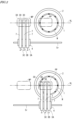
- FIG. 2 is a plan view of the substrate processing apparatus for explaining the functions of the nozzle support portion and the nozzle moving device in FIG.
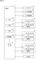
- FIG. 3 is a block diagram showing the configuration of a control system of the substrate processing apparatus of FIG.
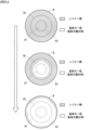
- FIG. 4 is a diagram showing an example of the time series change in the peeled state of the resist film during the removal process.
- FIG. 5 is a diagram showing another example of the time-series change in the peeled state of the resist film during the removal process.
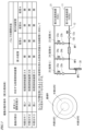
- FIG. 6 is a diagram showing a first specific example of a plurality of operating conditions that are set corresponding to a plurality of portions of the substrate W, respectively.
- FIG. 1 is a schematic diagram showing the configuration of a substrate processing apparatus according to an embodiment of the present invention.
- FIG. 2 is a plan view of the substrate processing apparatus for explaining the functions of the nozzle support portion and the nozzle moving device in
- FIG. 7 is a diagram showing a second specific example of a plurality of operating conditions that are set corresponding to a plurality of portions of the substrate W, respectively.
- FIG. 8 is a flow chart showing an example of a film removal process performed by the control unit of FIG.
- FIG. 9 is a schematic diagram showing the configuration of a substrate processing apparatus according to another embodiment.
- FIG. 10 is a diagram showing an example of the configuration of three processing liquid supplying devices according to another embodiment.
- substrate refers to a substrate for an FPD (Flat Panel Display) used in liquid crystal display devices or organic EL (Electro Luminescence) display devices, a semiconductor substrate, a substrate for an optical disk, a substrate for a magnetic disk, a substrate for a magneto-optical disk, a substrate for a photomask, a ceramic substrate, or a substrate for a solar cell, etc.
- FPD Fluorescence Deposition
- organic EL Electro Luminescence
- the substrate processing apparatus described below is a single-wafer type substrate processing apparatus used in a removal process for removing an unnecessary film (in this example, a resist film) formed on one surface (main surface) of a substrate.
- a substrate having an unnecessary film formed on one surface thereof is rotated in a horizontal position.
- SPM sulfuric acid hydrogen peroxide mixture
- SPM is supplied as a processing liquid to the one surface of the substrate.
- SPM is a mixture of sulfuric acid (H 2 SO 4 ) and hydrogen peroxide (H 2 O 2 ), and contains Caro's acid (H 2 SO 5 ).
- Caro's acid is generated by a chemical reaction between sulfuric acid and hydrogen peroxide, has a strong oxidizing power, and reacts with the unnecessary film to dissolve the film. As a result, the unnecessary film is peeled off and removed from the one surface of the substrate.
- the substrate processing apparatus 100 is provided at least partially within a chamber (not shown).
- the spin chuck 1 has a spin motor 1a, a spin base 1b, and chuck pins 1c.
- the spin motor 1a is provided at the bottom of the chamber so that its rotation shaft protrudes upward.
- the spin base 1b has a disk shape and is attached in a horizontal position to the upper end of the rotation shaft of the spin motor 1a.
- the multiple chuck pins 1c are provided on the upper surface of the spin base 1b and hold the peripheral edge of the substrate W.
- the spin motor 1a operates with the multiple chuck pins 1c holding the substrate W. This causes the substrate W to rotate around a vertical axis.
- a mechanical spin chuck 1 is used to hold the peripheral portion of the substrate W.
- this is not limiting, and instead of a mechanical spin chuck, an adsorption type spin chuck that adsorbs and holds the underside of the substrate W may be used.
- the cup 2 is provided to surround the spin chuck 1.
- the cup 2 is supported so that it can be raised and lowered by a cup lifting device 2D.
- the cup lifting device 2D includes an air cylinder or the like, and moves the cup 2 between two predetermined height positions (upper and lower positions described below).
- the three processing liquid supply devices 3A, 3B, and 3C basically have the same configuration.
- FIG. 1 the configuration of only processing liquid supply device 3C is shown in detail.
- the configuration of processing liquid supply device 3C will be explained as a representative of the three processing liquid supply devices 3A, 3B, and 3C.
- the processing liquid supply device 3C is mainly composed of a first liquid supply system 10, a second liquid supply system 20, and a nozzle 30.
- the first liquid supply system 10 includes a first liquid supply source 11, a first pipe 12, a valve 12a, an adjustment unit 12b, and an agitation unit 12c.
- the first liquid supply source 11 is a source of sulfuric acid, and is composed of a power utility facility of the factory or a liquid delivery device including a liquid storage unit.
- the upstream end of the first pipe 12 is connected to the first liquid supply source 11.
- the downstream end of the first pipe 12 is connected to the nozzle 30.
- the valve 12a, the adjustment unit 12b, and the agitation unit 12c are provided in the first liquid supply source 11 so as to be aligned in this order from the upstream end to the downstream end of the first liquid supply source 11.
- the portion located between the adjustment section 12b and the stirring section 12c is called the first portion MP1.
- the portion located between the stirring section 12c and the nozzle 30 is called the second portion MP2, and the portion located at the nozzle 30 is called the third portion MP3.
- a standby position WP is set at a position on the virtual line VL offset from the spin chuck 1 and cup 2 in a plan view.
- a processing position PP is set at a position on the virtual line VL overlapping with the spin chuck 1 in a plan view.
- the substrate processing apparatus 100 includes a rinse nozzle (not shown) and a rinse liquid supply system (not shown) that supplies rinse liquid to the rinse nozzle. After the resist film has been removed by the treatment liquid, the rinse nozzle ejects the rinse liquid toward one surface of the substrate W on which the treatment liquid remains. This removes the treatment liquid from the substrate W (rinsing process).
- the control unit 6 and the operation unit 9 will be described in detail later.
- Fig. 3 is a block diagram showing the configuration of the control system of the substrate processing apparatus 100 in Fig. 1.
- the control unit 6 includes a CPU (Central Processing Unit) 61, a RAM (Random Access Memory) 62, a ROM (Read Only Memory) 63, and a storage device 64.
- CPU Central Processing Unit
- RAM Random Access Memory
- ROM Read Only Memory
- RAM 62 is used as a working area for CPU 61.
- ROM 63 stores a system program.
- Storage device 64 includes a storage medium such as a hard disk or semiconductor memory, and stores a film removal program for performing the removal process. Furthermore, storage device 64 stores a number of operating conditions for the substrate processing apparatus 100 related to the removal process. The multiple operating conditions are conditions respectively associated with multiple portions of the substrate W that are the target of the removal process. The multiple operating conditions will be described in detail later.
- the film removal program may be provided in a state stored in a recording medium such as a CD-ROM 65, and installed in the ROM 63 or the storage device 64.
- the film removal program may be distributed from a server external to the substrate processing apparatus 100 via a communication network, and installed in the ROM 63 or the storage device 64.
- the control unit 6 also controls the cup lifting device 2D so that the cup 2 is held in the lower position when the substrate W is placed on the spin chuck 1, when the substrate W is removed from the spin chuck 1, and when no removal process is being performed.
- the lower position is the position of the cup 2 when the upper end of the cup 2 is lower than the substrate W held by the spin chuck 1.
- the control unit 6 also controls the nozzle movement device 5 so that the three nozzles 30 of the three processing liquid supply devices 3A, 3B, and 3C are held at the processing position PP while the removal process is being performed.
- the control unit 6 also controls the nozzle movement device 5 so that the three nozzles 30 of the three processing liquid supply devices 3A, 3B, and 3C are held at the standby position WP while the removal process is not being performed.
- the storage device 64 of the control unit 6 stores a number of operating conditions for the substrate processing apparatus 100 related to the removal process.
- the operating conditions include information regarding the operation of each of the valves 12a, 23a, 24a, 25a and the adjustment units 12b, 23b, 24b, 25b of the three processing liquid supply devices 3A, 3B, 3C.
- the control unit 6 controls the valves 12a, 23a, 24a, 25a and adjustment units 12b, 23b, 24b, 25b of the three processing liquid supply devices 3A, 3B, 3C based on a number of operating conditions during the removal process.
- hydrogen peroxide is supplied from the second liquid supply system 20 to at least two of the first portion MP1, the second portion MP2, and the third portion MP3 of the liquid flow path.
- SPM processing liquid
- the operation unit 9 in FIG. 1 includes a keyboard and a pointing device, and is configured to be operable by the user. The user can input the above-mentioned multiple operating conditions by operating the operation unit 9. When multiple operating conditions are input in the operation unit 9, the control unit 6 stores the input operating conditions in the storage device 64.
- ease of removal means that the resist film is easily removed
- low ease of removal means that the resist film is difficult to remove
- the ease of removal for one substrate W may differ from one another in multiple parts of one surface of the substrate W depending on the material constituting the resist film formed on the substrate W, the thickness distribution of the resist film, and the distribution of adhesion between the resist film and the substrate W.
- the distribution of ease of removal on one surface of one substrate W can be understood to some extent by performing a removal process in advance on a sample substrate of the same type as the substrate W or by simulating the removal process.
- the ability of the processing liquid to remove the resist film is referred to as the film removal ability.
- the degree of film removal ability represents the degree of reactivity of the processing liquid with respect to the resist film formed on the substrate W, and is determined primarily by the Caro's acid concentration of the processing liquid.
- FIG. 4 shows an example of the time series change in the peeling state of the resist film during removal processing.
- the top, middle and bottom rows show plan views in chronological order, each showing the state of the resist film when a processing liquid having a common film removal capability is supplied to the entire surface of the substrate W.
- the resist film present on the substrate W is shown as a dot pattern.
- the time series change in the peeling state of the resist film as shown in FIG. 4 can be obtained, for example, by capturing images of one surface of the substrate W during the removal process with a camera every predetermined time.
- an inner portion R1, a middle portion R2, and an outer portion R3 are defined on one surface of the substrate W.
- the inner portion R1 is located at the center of the substrate W.
- the middle portion R2 has a circular ring shape and surrounds the inner portion R1.
- the outer portion R3 has a circular ring shape that includes the outer peripheral edge of the substrate W and surrounds the middle portion R2.
- the radius of the inner portion R1, the width of the middle portion R2 in the radial direction of the substrate W, and the width of the outer portion R3 in the radial direction of the substrate W are all equal to each other.
- the substrate W corresponding to the example of Figure 4 has high removability in the inner portion R1, medium removability in the middle portion R2, and low removability in the outer portion R3.
- FIG. 5 shows another example of the time series change in the peeling state of the resist film during removal processing.
- FIG. 5 similar to the example of FIG. 4, plan views showing the state of the resist film when a processing liquid having a common film removal ability is supplied to the entire surface of the substrate W are shown in chronological order in the upper, middle and lower rows. In each of the upper, middle and lower rows of FIG. 5, the resist film present on the substrate W is shown as a dot pattern.
- the substrate W corresponding to the example of Figure 5 has low removability in the inner portion R1, medium removability in the middle portion R2, and high removability in the outer portion R3.
- the distribution of removability of the resist film on the substrate W as shown in Figures 4 and 5 can be understood to some extent by performing a removal process on a sample substrate W in advance or by performing a simulation. Furthermore, according to the understood distribution of removability, it is possible to predict the film removal capability of the processing liquid to be supplied to each of the multiple portions of the substrate W, as described above.
- the film removal capability of the processing liquid to be supplied to each of the multiple portions of the substrate W is predicted according to the ease of removal of the resist film on one surface of the substrate W to be processed. Then, information indicating the relationship between each of the multiple portions of the substrate W and the preferred film removal capability corresponding to that portion is obtained as substrate portion information.
- three processing liquid supply devices 3A, 3B, and 3C are provided corresponding to the inner portion R1, the middle portion R2, and the outer portion R3 of the substrate W, respectively.
- the film removal capability of the processing liquid discharged from each nozzle 30 of the processing liquid supply devices 3A, 3B, and 3C can be adjusted by controlling the operation of each part of the first liquid supply system 10 and the second liquid supply system 20 of the processing liquid supply devices.
- the operating conditions of the first liquid supply system 10 and the second liquid supply system 20 of the processing liquid supply device 3A corresponding to the inner portion R1 of the substrate W are determined based on the acquired substrate portion information. Also, the operating conditions of the first liquid supply system 10 and the second liquid supply system 20 of the processing liquid supply device 3B corresponding to the middle portion R2 of the substrate W are determined based on the substrate portion information. Furthermore, the operating conditions of the first liquid supply system 10 and the second liquid supply system 20 of the processing liquid supply device 3C corresponding to the outer portion R3 of the substrate W are determined based on the substrate portion information.
- a plurality of operating conditions corresponding to each of a plurality of portions of the substrate W are input by, for example, the user operating the operation unit 9, and are stored in the storage device 64 of FIG. 3.
- the degree of film removal ability indicates the reactivity of the processing liquid with respect to the resist film formed on the substrate W, and is determined mainly by the Caro's acid concentration of the processing liquid.
- the film removal ability of the processing liquid discharged from the nozzle 30 can be adjusted by controlling the multiple valves 12a, 23a, 24a, and 25a and the multiple adjustment units 12b, 23b, 24b, and 25b.
- the valve 24a is opened and the adjustment unit 24b is controlled so that hydrogen peroxide flows at a predetermined flow rate in the second sub-pipe 24.
- new hydrogen peroxide that has not been heated to a high temperature is supplied to the second part MP2, thereby generating new Caro's acid.
- the concentration of Caro's acid in the treatment liquid flowing through the first pipe 12 downstream of the second part MP2 increases compared to the treatment liquid flowing through the agitation unit 12c.
- the valve 25a is opened and the adjustment unit 25b is controlled so that hydrogen peroxide flows at a predetermined flow rate in the second sub-pipe 25.
- new hydrogen peroxide that has not been heated to a high temperature is supplied to the third portion MP3, thereby generating new Caro's acid.
- the concentration of Caro's acid in the treatment liquid discharged from the nozzle 30 increases compared to the treatment liquid flowing through the agitation unit 12c.
- the inventor confirmed that the Caro's acid concentration in the treatment liquid varies depending on the mixing ratio of sulfuric acid and hydrogen peroxide in each of the multiple parts (MP1, MP2, MP3) of the liquid flow path. Based on this, the inventor discovered that when sulfuric acid and hydrogen peroxide are mixed in multiple parts (MP1, MP2, MP3) of the liquid flow path, the Caro's acid concentration in the treatment liquid ejected from nozzle 30 tends to be higher by increasing the mixing ratio of hydrogen peroxide to sulfuric acid in the downstream part compared to the upstream part.
- the inventor has found that the Caro's acid concentration of the treatment liquid generated by mixing sulfuric acid and hydrogen peroxide at a predetermined mixing ratio in the first part MP1 and the second part MP2 tends to be higher than the Caro's acid concentration of the treatment liquid generated when sulfuric acid and hydrogen peroxide are mixed at a predetermined mixing ratio in the first part MP1 and the third part MP3.
- the inventor has found that the further away from the nozzle 30 the part to which hydrogen peroxide is added is in the liquid flow path, the higher the Caro's acid concentration of the treatment liquid ejected from the nozzle 30 tends to be.
- FIG. 6 is a diagram showing a first specific example of multiple operating conditions that are set corresponding to multiple portions of a substrate W.
- the operating conditions of three processing liquid supply devices 3A, 3B, and 3C that are set for the inner portion R1, middle portion R2, and outer portion R3 of the substrate W, respectively, are shown in a table.
- an explanatory diagram of the multiple portions of the substrate W is shown below the table to make the table easier to understand.
- a configuration diagram of each processing liquid supply device 3A, 3B, and 3C is shown to make the table easier to understand.
- the first specific example in FIG. 6 is set for a substrate W having a resist film with high removability in the inner portion R1, slightly higher removability in the middle portion R2, and low removability in the outer portion R3.
- a processing liquid with low film removal capability to the inner portion R1
- a processing liquid with slightly lower film removal capability to the middle portion R2
- a processing liquid with high film removal capability to the outer portion R3.
- the target ratio of the flow rates of the liquids flowing through the first pipe 12, pipe A, pipe B, and pipe C is set to 100:10:0:90 so that the Caro's acid concentration of the treatment liquid produced is low.
- the target ratio of the flow rates of the liquid flowing through the first pipe 12 is set to 100:20:0:80 so that the Caro's acid concentration of the treatment liquid generated is slightly low.
- the target ratio of the flow rates of the liquid flowing through the first pipe 12 is set to 100:30:70:0 so that the concentration of Caro's acid in the generated treatment liquid is high.
- the valves 12a, 23a, 24a, and 25a are open in the processing liquid supplying apparatus 3A. Furthermore, the adjustment units 12b, 23b, 24b, and 25b are each controlled so that the ratio of the flow rates of the liquids flowing through the first pipe 12, pipe A, pipe B, and pipe C becomes the target ratio of 100:10:0:90. In this case, since the target ratio for pipe B is 0, the valve 24a for pipe B may be closed.
- the valves 12a, 23a, 24a, and 25a are opened. Furthermore, the adjustment units 12b, 23b, 24b, and 25b are each controlled so that the ratio of the flow rates of the liquids flowing through the first pipe 12, pipe A, pipe B, and pipe C becomes the target ratio of 100:20:0:80. In this case, since the target ratio for pipe B is 0, the valve 24a for pipe B may be closed.
- the valves 12a, 23a, 24a, and 25a are in an open state. Furthermore, the adjustment units 12b, 23b, 24b, and 25b are each controlled so that the ratio of the flow rates of the liquids flowing through the first pipe 12, pipe A, pipe B, and pipe C becomes the target ratio of 100:30:70:0. In this case, since the target ratio for pipe C is 0, the valve 25a for pipe B may be in a closed state.
- Fig. 7 is a diagram showing a second specific example of multiple operation conditions set corresponding to multiple parts of the substrate W.
- the operation conditions of the three processing liquid supplying devices 3A, 3B, and 3C set for the inner part R1, the middle part R2, and the outer part R3 of the substrate W, respectively, are shown in a table.
- an explanatory diagram of the multiple parts of the substrate W is shown below the table to facilitate understanding of the table.
- a configuration diagram of each processing liquid supplying device 3A, 3B, and 3C is shown to facilitate understanding of the table.
- the second specific example in FIG. 7 is set for a substrate W having a resist film with high removability in the inner portion R1, high removability in the middle portion R2, and low removability in the outer portion R3.
- a processing liquid with low film removal capability to the inner portion R1
- a processing liquid with low film removal capability to the middle portion R2
- a processing liquid with high film removal capability to the outer portion R3.
- valve 12a when valve 12a is open, the flow rate of the liquid flowing through the first pipe 12 is predefined. Also, when valves 23a, 24a, and 25a are open, the flow rates of the liquid flowing through pipes A, B, and C are predefined. In this case, the Caro's acid concentration of the treatment liquid discharged from the nozzle 30 varies depending on the open/closed states of valve 12a of the first pipe 12, valve 23a of pipe A, valve 24a of pipe B, and valve 25a of pipe C.
- the operating conditions of the treatment liquid supplying device 3B corresponding to the middle portion R2 are set so that the open/closed states of the valves 12a, 23a, 24a, and 25a are set to "open,” “open,” “closed,” and “open,” respectively, so that the concentration of Caro's acid in the treatment liquid produced is low.
- the valves 12a, 23a, and 25a are open, and the valve 24a is closed.
- the valves 12a, 23a, and 25a are open, and the valve 24a is closed.
- the valves 12a, 23a, and 24a are open, and the valve 25a is closed.
- the multiple adjustment units 12b, 23b, 24b, and 25b are controlled so that they are in states corresponding to the predetermined flow rates for the first pipe 12, pipe A, pipe B, and pipe C, respectively.
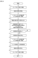
- FIG. 8 is a flowchart showing an example of a film removal processing by the control unit 6 of Fig. 1.
- the film removal processing described below is performed by the CPU 61 of the control unit 6 executing a film removal program stored in the storage device 64 on the RAM 62.
- the CPU 61 controls the cup lifting device 2D to move the cup 2 from the lower position to the upper position (step S11).
- the CPU 61 also controls the spin motor 1a to rotate the substrate W held by the multiple chuck pins 1c on the spin base 1b (step S12).
- the CPU 61 controls the nozzle moving device 5 to move the three nozzles 30 of the three processing liquid supply devices 3A, 3B, 3C from the standby position WP to the processing position PP (step S13).
- the CPU 61 reads a plurality of operating conditions stored in the storage device 64 (step S14).
- the CPU 61 controls the valves 12a, 23a, 24a, 25a and the adjustment units 12b, 23b, 24b, 25b of the three processing liquid supply devices 3A, 3B, 3C based on the read plurality of operating conditions (step S15).
- processing liquids having the corresponding film removal capabilities are supplied to the inner portion R1, the middle portion R2, and the outer portion R3 of the substrate W.
- the CPU 61 measures the elapsed time from the start of processing in step S15. The CPU 61 also determines whether or not the supply of the processing liquid should be stopped based on whether or not the measured time has reached the predetermined supply time (step S16).
- step S16 If the supply of the treatment liquid should not be stopped, the CPU 61 repeats the process of step S16. On the other hand, if the supply of the treatment liquid should be stopped, the CPU 61 stops the supply of the treatment liquid by closing the multiple valves 12a, 23a, 24a, and 25a of the three treatment liquid supply devices 3A, 3B, and 3C (step S17).
- the CPU 61 controls the nozzle moving device 5 to move the three nozzles 30 of the three processing liquid supply devices 3A, 3B, 3C from the processing position PP to the standby position WP (step S18).
- the CPU 61 also controls a rinse liquid supply system (not shown) and the spin motor 1a to perform a rinse process and a drying process on the substrate W from which the resist film has been removed (step S19).
- the drying process in step S19 is a so-called spin drying process in which the substrate W after the rinse process is rotated at high speed to dry the substrate W.
- the CPU 61 controls the spin motor 1a to stop the rotation of the substrate W (step S20).
- the CPU 61 also controls the cup lifting device 2D to move the cup 2 from the upper position to the lower position (step S21), completing the series of processes.
- the three processing liquid supplying devices 3A, 3B, and 3C are controlled to follow a plurality of operating conditions corresponding to a plurality of portions (inner portion R1, middle portion R2, and outer portion R3) of one surface of the substrate W.
- processing liquids having appropriate film removal capabilities for removing the resist film are respectively supplied to the plurality of portions of one surface of the substrate W and collide with the portions.
- the film removal capabilities of the processing liquid are most effective when the processing liquid is discharged from the nozzle 30 and reaches (collides with) the resist film on the substrate W.
- the substrate processing apparatus 100 in the above embodiment is provided with processing liquid supply devices 3A, 3B, and 3C corresponding to the inner portion R1, middle portion R2, and outer portion R3 of the substrate W, respectively, but the present invention is not limited to this.
- the substrate processing apparatus 100 may have only one processing liquid supply device.
- Figure 9 is a schematic diagram showing the configuration of a substrate processing apparatus 100 according to another embodiment.
- the substrate processing apparatus 100 of Figure 9 has only one processing liquid supply device 3 as a configuration for supplying processing liquid to the substrate W.
- the arm member 7 (see Figure 2) of the processing liquid supply device 3 is moved in the rail direction during the removal process. As a result, the processing liquid ejected from one nozzle 30 is sequentially supplied to multiple portions of one surface of the substrate W.
- the substrate processing apparatus 100 of FIG. 9 is set with the multiple operating conditions of FIG. 6.
- the nozzle 30 is positioned to face the internal portion R1 of the substrate W.
- the valves 12a, 23a, 24a, 25a are opened.
- the adjustment units 12b, 23b, 24b, 25b are each controlled so that the ratio of the flow rates of the liquids flowing through the first pipe 12, pipe A, pipe B, and pipe C becomes the target ratio of 100:10:0:90.
- the nozzle 30 is positioned to face the middle portion R2 of the substrate W.
- the valves 12a, 23a, 24a, 25a are opened.
- the adjustment units 12b, 23b, 24b, 25b are each controlled so that the ratio of the flow rates of the liquids flowing through the first pipe 12, pipe A, pipe B, and pipe C becomes the target ratio of 100:20:0:80.
- the substrate processing apparatus 100 of FIG. 9 by moving one processing liquid supplying device 3, processing liquids each having appropriate film removal capabilities are sequentially supplied to the inner portion R1, middle portion R2, and outer portion R3 of the substrate W. This eliminates the need to provide multiple processing liquid supplying devices 3 in the substrate processing apparatus 100. Therefore, the substrate processing apparatus 100 of FIG. 9 has a simplified configuration with an reduced number of parts.
- a nozzle 30 is connected to the downstream end of a first pipe 12Y drawn out from the processing liquid supplying device 3A.
- a valve 12d is provided in the first pipe 12Y, similar to the valve 12d in the processing liquid supplying device 3A.
- the portion located between the valve 12d and the nozzle 30 is called the sixth portion MP6.
- the portion located at the nozzle 30 is called the seventh portion MP7.
- the portion of the second main pipe 22 drawn out from the treatment liquid supplying device 3B is led into the treatment liquid supplying device 3C.
- the downstream end of the second main pipe 22 is located inside the treatment liquid supplying device 3C.
- the portion including the downstream end of the second main pipe 22 constitutes part of the treatment liquid supplying device 3C.
- One branch is provided in the portion of the second main pipe 22 that constitutes part of the treatment liquid supplying device 3C.
- Two second sub-pipes 28, 29 are connected so as to connect one branch and the downstream end of the second main pipe 22 to the sixth part MP6 and the seventh part MP7 of the liquid flow path, respectively.
- a valve 28a and an adjustment unit 28b are provided in the second sub-pipe 28, and a valve 29a and an adjustment unit 29b are provided in the second sub-pipe 29.
- a portion of the configuration of the processing liquid supply device 3A is used in common with the other processing liquid supply devices 3B and 3C as a common supply system 40.
- the substrate processing apparatus 100 has three processing liquid supply devices 3A, 3B, and 3C, the present invention is not limited to this.
- the substrate processing apparatus 100 may have two processing liquid supply devices, or may have four or more processing liquid supply devices.
- the greater the number of processing liquid supply devices the greater the portion of the substrate W that can be processed simultaneously, improving the processing efficiency of the substrate W.
- the fewer the number of processing liquid supply devices the less the increase in the number of parts of the substrate processing apparatus 100 and the simpler the configuration.
- the first liquid supply source 11 is a source of sulfuric acid and the second liquid supply source 21 is a source of hydrogen peroxide, but the present invention is not limited to this.
- the first liquid supply source 11 may be a source of hydrogen peroxide and the second liquid supply source 21 may be a source of sulfuric acid.
- the second liquid supply system 20 of each of the processing liquid supply devices 3A, 3B, and 3C has three second sub-pipes 23, 24, and 25 as piping for mixing hydrogen peroxide solution with sulfuric acid, but the present invention is not limited to this.
- the second liquid supply system 20 may have only two second sub-pipes, or may have four or more second sub-pipes. When the second liquid supply system 20 has four or more second sub-pipes, the sulfuric acid and hydrogen peroxide solution can be mixed in four or more parts of the liquid flow path formed by the first pipe 12 and the nozzle 30. This increases the degree of freedom of the operating conditions that can be set to generate the processing liquid.
- the substrate processing apparatus 100 may also include a supply device (SC1 supply device) that supplies a mixed liquid (SC1) of ammonia water and hydrogen peroxide water as another processing liquid to the substrate W held by the spin chuck 1.
- SC1 supply device supplies a mixed liquid (SC1) of ammonia water and hydrogen peroxide water as another processing liquid to the substrate W held by the spin chuck 1.
- SC1 supply device supplies a mixed liquid (SC1) of ammonia water and hydrogen peroxide water as another processing liquid to the substrate W held by the spin chuck 1.
- the substrate processing apparatus is A substrate processing apparatus, which performs a removal process for removing an unnecessary film formed on one surface of a substrate using a processing solution containing Caro's acid,
- the Caro's acid is produced by mixing one of sulfuric acid and hydrogen peroxide solution as a first liquid and the other of sulfuric acid and hydrogen peroxide solution as a second liquid
- the substrate processing apparatus includes: a nozzle that ejects the processing liquid so as to impinge on a plurality of portions of the one surface of the substrate; a first liquid supply system including a first pipe connected to the nozzle and supplying the first liquid to the nozzle through the first pipe; a second liquid supply system including a plurality of second pipes respectively connected to a plurality of different portions of a liquid flow path formed by the nozzle and the first pipe, and supplying the second liquid to the liquid flow path through any one of the plurality of second pipes; a control unit that controls the first liquid supply system and the second liquid supply
- the nozzle includes a plurality of nozzles respectively corresponding to the plurality of portions of the one surface of the substrate;
- the first liquid supply system includes a plurality of first liquid supply systems respectively corresponding to the plurality of nozzles;
- the second liquid supply system includes a plurality of second liquid supply systems respectively corresponding to the plurality of nozzles,
- the substrate processing method includes: The method may include supporting the plurality of nozzles such that, during the removal process, outlets of the plurality of nozzles for ejecting processing liquid face the plurality of portions of the one surface of the substrate, respectively.
Landscapes
- Cleaning Or Drying Semiconductors (AREA)
- Exposure Of Semiconductors, Excluding Electron Or Ion Beam Exposure (AREA)
- Manufacturing Of Printed Circuit Boards (AREA)
Abstract
基板処理装置は、処理液を吐出するノズルと、ノズルに接続された第1の配管を含み、第1の配管を通してノズルに第1の液を供給する第1の液供給系と、ノズルおよび第1の配管により形成される液流路のうち互いに異なる複数の部分にそれぞれ接続された複数の第2の副配管を含み、それらの副配管のいずれかを通して液流路に第2の液を供給する第2の液供給系と、基板上に形成された膜の除去処理時に、複数の動作条件に基づいて第1の液供給系および第2の液供給系を制御する制御部とを備える。複数の動作条件は、基板の複数の部分の各々にそれぞれ対応付けられている。
Description
本発明は、基板の一面上に形成された不要な膜を除去する基板処理装置および基板処理方法に関する。
半導体基板、液晶表示装置もしくは有機EL(Electro Luminescence)表示装置等のFPD(Flat Panel Display)用基板、光ディスク用基板、磁気ディスク用基板、光磁気ディスク用基板、フォトマスク用基板、セラミック基板または太陽電池用基板等の基板に種々の処理を行うために、基板処理装置が用いられる。
特許文献1に記載された基板処理装置においては、基板(ウェハ)の一面上に形成された不要なレジスト膜がSPM(Sulfuric acid hydrogen peroxide mixture)を用いて除去される。より具体的には、レジスト膜を有する基板がスピンチャックにより水平姿勢で保持され、鉛直軸の周りで回転される。この状態で、回転する基板の上方の位置にSPMノズルが配置され、当該SPMノズルから基板の回転中心に向かってSPMが供給される。SPMは、硫酸(H2SO4)と過酸化水素水(H2O2)との混合液であり、強い酸化力を有する。それにより、基板上のレジスト膜が、SPMの酸化力により基板の一面から剥離され、除去される。
ところで、レジスト膜を有する基板上にSPMが供給される場合、レジスト膜の複数の部分は、必ずしも均一に除去されるわけではない。例えば、基板上に形成されるレジスト膜は、レジスト膜の厚さのばらつきおよび基板とレジスト膜との間の密着力のばらつき等の要因により、基板の一面から除去されやすい部分と、基板の一面から除去されにくい部分とを含む場合がある。そこで、レジスト膜のうち基板の一面から除去されにくい部分を確実に除去するために、基板に対するSPMの供給時間を長くすることが考えられる。
しかしながら、レジスト膜のうち基板の一面から除去されやすい部分に、長時間に渡ってSPMが供給されると、レジスト膜が除去された後、露出する基板の部分にSPMが長時間に渡って供給されることになる。この場合、基板の一部がSPMの酸化力により損傷を受ける可能性がある。また、長時間に渡るSPMの供給は、基板1枚当たりのSPMの使用量を増大させる。
本発明の目的は、基板に損傷を与えることなく基板の一面上に形成された不要な膜を除去するとともに処理液の使用量を低減することを可能にする基板処理装置および基板処理方法を提供することである。
本発明の一局面に従う基板処理装置は、カロ酸を含む処理液により基板の一面上に形成された不要な膜を除去する除去処理を行う基板処理装置であって、前記カロ酸は、硫酸および過酸化水素水のうち一方を第1の液とし、硫酸および過酸化水素水のうち他方を第2の液とした場合に、前記第1の液と前記第2の液とを混合することにより生成され、前記基板処理装置は、前記基板の前記一面の複数の部分に衝突するように前記処理液を吐出するノズルと、前記ノズルに接続された第1の配管を含み、前記第1の配管を通して前記ノズルに前記第1の液を供給する第1の液供給系と、前記ノズルおよび前記第1の配管により形成される液流路のうち互いに異なる複数の部分にそれぞれ接続された複数の第2の配管を含み、前記複数の第2の配管のうちいずれかを通して前記液流路に前記第2の液を供給する第2の液供給系と、前記除去処理時に、予め定められた複数の動作条件に基づいて前記第1の液供給系および前記第2の液供給系を制御する制御部とを備え、前記複数の動作条件は、前記基板の前記一面の複数の部分の各々に当該部分に対応する膜除去能力を有する処理液が衝突するように、前記基板の複数の部分にそれぞれ対応付けられた条件である。
本発明の他の局面に従う基板処理方法は、カロ酸を含む処理液により基板の一面上に形成された不要な膜を除去する除去処理を行う基板処理装置を用いた基板処理方法であって、前記カロ酸は、硫酸および過酸化水素水のうち一方を第1の液とし、硫酸および過酸化水素水のうち他方を第2の液とした場合に、前記第1の液と前記第2の液とを混合することにより生成され、前記基板処理装置は、前記基板の前記一面の複数の部分に衝突するように前記処理液を吐出するノズルと、前記ノズルに接続された第1の配管を含み、前記第1の配管を通して前記ノズルに前記第1の液を供給する第1の液供給系と、前記ノズルおよび前記第1の配管により形成される液流路のうち互いに異なる複数の部分にそれぞれ接続された複数の第2の配管を含み、前記複数の第2の配管のうちいずれかを通して前記第1の配管内に前記第2の液を供給する第2の液供給系とを備え、前記基板処理方法は、前記基板の前記一面の前記複数の部分の各々について、当該部分に供給されるべき処理液の膜除去能力に関する情報を取得するステップと、取得された前記情報に基づいて、前記基板の前記一面の前記複数の部分にそれぞれ対応する膜除去能力を有する処理液が衝突するように、前記基板の複数の部分の各々に対応する前記第1の液供給系および前記第2の液供給系の動作条件を設定するステップと、設定された前記第1の液供給系および前記第2の液供給系の動作条件に基づいて前記第1の液供給系および前記第2の液供給系を制御するステップとを含む。
本発明によれば、基板に損傷を与えることなく基板の一面上に形成された不要な膜を除去するとともに処理液の使用量を低減することが可能になる。
以下、本発明の一実施の形態に係る基板処理装置および基板処理方法について図面を参照しつつ説明する。以下の説明において、基板とは、液晶表示装置または有機EL(Electro Luminescence)表示装置等に用いられるFPD(Flat Panel Display)用基板、半導体基板、光ディスク用基板、磁気ディスク用基板、光磁気ディスク用基板、フォトマスク用基板、セラミック基板または太陽電池用基板等をいう。
また、以下に説明する基板処理装置は、基板の一面(主面)上に形成された不要な膜(本例では、レジスト膜)を除去する除去処理に用いられる枚葉式の基板処理装置である。本実施の形態に係る除去処理においては、一面に不要な膜が形成された基板が水平姿勢で回転される。その基板の一面に、処理液としてSPM(Sulfuric acid hydrogen peroxide mixture)が供給される。SPMは、硫酸(H2SO4)と過酸化水素水(H2O2)との混合液であり、カロ酸(H2SO5)を含む。カロ酸は、硫酸と過酸化水素水との間で化学反応が生じることにより生成され、強い酸化力を有し、不要な膜と反応することにより当該膜を溶解する。それにより、基板の一面から不要な膜が剥離され、除去される。
<1>基板処理装置の構成
図1は、本発明の一実施の形態に係る基板処理装置の構成を示す模式図である。図1に示すように、基板処理装置100は、主としてスピンチャック1、カップ2、カップ昇降装置2D、3つの処理液供給装置3A,3B,3C、ノズル支持部4、ノズル移動装置5、制御部6および操作部9を備える。
図1は、本発明の一実施の形態に係る基板処理装置の構成を示す模式図である。図1に示すように、基板処理装置100は、主としてスピンチャック1、カップ2、カップ昇降装置2D、3つの処理液供給装置3A,3B,3C、ノズル支持部4、ノズル移動装置5、制御部6および操作部9を備える。
基板処理装置100は、少なくとも一部が図示しないチャンバ内に設けられる。スピンチャック1は、スピンモータ1a、スピンベース1bおよびチャックピン1cを有する。スピンモータ1aは、回転軸が上方に向かって突出するように、チャンバの底部に設けられる。スピンベース1bは、円板形状を有し、スピンモータ1aの回転軸の上端部に水平姿勢で取り付けられる。複数のチャックピン1cは、スピンベース1bの上面上に設けられ、基板Wの周縁部を保持する。複数のチャックピン1cが基板Wを保持する状態でスピンモータ1aが動作する。それにより、基板Wが鉛直軸の周りで回転する。
上記のように、本例では、基板Wの周縁部を保持する機械式のスピンチャック1が用いられる。これに限らず、機械式のスピンチャックに代えて、基板Wの下面を吸着保持する吸着式のスピンチャックが用いられてもよい。
スピンチャック1を取り囲むように、カップ2が設けられている。カップ2は、カップ昇降装置2Dにより昇降可能に支持される。カップ昇降装置2Dは、エアシリンダ等を含み、予め定められた2つの高さ位置(後述する上位置および下位置)の間でカップ2を移動させる。
3つの処理液供給装置3A,3B,3Cは、基本的に同じ構成を有する。図1では、処理液供給装置3Cのみ構成の詳細が示される。3つの処理液供給装置3A,3B,3Cを代表して、処理液供給装置3Cの構成を説明する。
処理液供給装置3Cは、主として第1の液供給系10、第2の液供給系20およびノズル30から構成される。第1の液供給系10は、第1の液供給源11、第1の配管12、バルブ12a、調整部12bおよび攪拌部12cを含む。第1の液供給源11は、硫酸の供給源であり、工場の用力設備または液貯留部を含む送液装置等で構成される。第1の配管12の上流端は、第1の液供給源11に接続されている。第1の配管12の下流端は、ノズル30に接続されている。バルブ12a、調整部12bおよび攪拌部12cは、この順で第1の液供給源11の上流端から下流端に向かって並ぶように、第1の液供給源11に設けられている。
バルブ12aは、例えばボールバルブであり、開状態であるときに第1の配管12内の液体の流通を許容し、閉状態であるときに第1の配管12内の液体の流通を遮断する。調整部12bは、モータニードルバルブまたはレギュレータ等の流量調整器を含み、第1の配管12を流れる液体の流量を調整する。本例では、調整部12bは、モータニードルバルブである。攪拌部12cは、例えばインラインミキサであり、第1の配管12内で渦流等を生じさせることにより第1の配管12を流れる複数種類の液体(本例では、硫酸および過酸化水素水)を混合する。
本実施の形態においては、第1の配管12およびノズル30により形成される液流路において、調整部12bと攪拌部12cとの間に位置する部分を第1の部分MP1と呼ぶ。また、攪拌部12cとノズル30との間に位置する部分を第2の部分MP2と呼び、ノズル30に位置する部分を第3の部分MP3と呼ぶ。
第2の液供給系20は、第2の液供給源21、第2の主配管22、複数(本例では3つ)の第2の副配管23,24,25、複数(本例では3つ)のバルブ23a,24a,25aおよび複数の(本例では3つ)の調整部23b,24b,25bを含む。第2の液供給源21は、過酸化水素水の供給源であり、第1の液供給源11の例と同様に、工場の用力設備または液貯留部を含む送液装置等で構成される。
第2の主配管22の上流端は、第2の液供給源21に接続されている。第2の主配管22は、上流から下流に向かって並ぶ複数(本例では2つ)の分岐部を有する。第2の副配管23,24,25の上流端は、第2の主配管22の上流側の分岐部、第2の主配管22の下流側の分岐部、および第2の主配管22の下流端にそれぞれ接続されている。一方、第2の副配管23,24,25の下流端は、上記の液流路の第1の部分MP1、第2の部分MP2および第3の部分MP3にそれぞれ接続されている。
第2の副配管23には、バルブ23aおよび調整部23bがこの順で上流から下流に向かって並ぶように設けられている。第2の副配管24には、バルブ24aおよび調整部24bがこの順で上流から下流に向かって並ぶように設けられている。第2の副配管25には、バルブ25aおよび調整部25bがこの順で上流から下流に向かって並ぶように設けられている。
バルブ23a,24a,25aは、バルブ12aと同じ構成を有する。また、調整部23b,24b,25bは、調整部12bと同じ構成を有する。なお、バルブ12a,23a,24a,25aのうち一部のバルブは、他のバルブと異なる構成を有してもよい。また、調整部12b,23b,24b,25bのうち一部の調整部は、他の調整部と異なる構成を有してもよい。
上記の3つの処理液供給装置3A,3B,3Cの各々においては、第1の液供給系10のうちの一部の構成および第2の液供給系20のうちの一部の構成が、例えば硬質な樹脂製のアーム部材7(図2)により支持される。
図2は、図1のノズル支持部4およびノズル移動装置5の機能を説明するための基板処理装置100の平面図である。図2の上段に示すように、平面視でスピンチャック1およびカップ2の側方には、チャンバの底部にレール5rが設けられている。レール5rは、スピンチャック1およびカップ2に近接する位置で、一方向に延びるように設けられている。以下の説明では、平面視でレール5rが延びる方向をレール方向と呼ぶ。また、平面視で、スピンチャック1により保持される基板Wの中心を通りかつレール方向に延びる直線を仮想線VLと呼ぶ。
3つの処理液供給装置3A,3B,3Cの各々に対応するアーム部材7は、例えば棒形状を有し、先端部分でノズル30を支持する。ノズル支持部4は、3つのノズル30が仮想線VL上に並ぶように3本のアーム部材7を支持するとともに、レール方向に移動可能にレール5r上に設けられている。ノズル支持部4には、ノズル移動装置5の一部を構成するモータが取り付けられている。これにより、ノズル支持部4は、ノズル移動装置5が動作することにより、レール5r上を移動する。
基板処理装置100には、平面視で、スピンチャック1およびカップ2からずれた仮想線VL上の位置に待機位置WPが設定されている。また、平面視で、スピンチャック1に重なる仮想線VL上の位置に処理位置PPが設定されている。基板処理装置100が、除去処理を行わない待機状態にある場合、3つの処理液供給装置3A,3B,3Cの3つのノズル30は、図2の上段に示すように、平面視で待機位置WPに保持される。一方、基板処理装置100が、除去処理を行う場合、3つの処理液供給装置3A,3B,3Cの3つのノズル30は、図2の下段に示すように、平面視で処理位置PPに保持される。
本実施の形態においては、除去処理時に3つのノズル30が処理位置PPに保持された状態で、3つのノズル30が、スピンチャック1により保持される基板Wに対して予め定められた位置に位置決めされる。
具体的には、処理液供給装置3Aのノズル30は、平面視で、基板Wの中心部分(後述する内部分R1(図4等))に重なるように位置決めされる。また、処理液供給装置3Bのノズル30は、平面視で、基板Wの中心と基板Wの外周端部との間の中間部分(後述する中部分R2(図4等))に重なるように位置決めされる。また、処理液供給装置3Cのノズル30は、平面視で、基板Wの周縁部分(後述する外部分R3(図4等))に重なるように位置決めされる。このように位置決めされた状態で、各ノズル30は、当該ノズル30の吐出口が基板Wの一面に対向するように支持される。これにより、除去処理時には、各ノズル30の吐出口から基板Wの一面における3つの部分に向かってそれぞれ処理液が吐出される。吐出された処理液は、基板Wの一面(正確には、基板Wの一面または基板Wの一面を覆うレジスト膜)に衝突する。
なお、本実施の形態に係る基板処理装置100は、図示しないリンスノズルと、リンスノズルにリンス液を供給する図示しないリンス液供給系とを含む。リンスノズルは、処理液によりレジスト膜が除去された後、処理液が残留する基板Wの一面に向けてリンス液を吐出する。これにより、基板W上の処理液が除去される(リンス処理)。制御部6および操作部9についての詳細は後述する。
<2>基板処理装置の制御系
基板処理装置100の制御系について、図1の制御部6および操作部9の構成とともに説明する。図3は、図1の基板処理装置100の制御系統の構成を示すブロック図である。図3に示すように、制御部6は、CPU(中央演算処理装置)61、RAM(ランダムアクセスメモリ)62、ROM(リードオンリメモリ)63および記憶装置64を含む。
基板処理装置100の制御系について、図1の制御部6および操作部9の構成とともに説明する。図3は、図1の基板処理装置100の制御系統の構成を示すブロック図である。図3に示すように、制御部6は、CPU(中央演算処理装置)61、RAM(ランダムアクセスメモリ)62、ROM(リードオンリメモリ)63および記憶装置64を含む。
RAM62は、CPU61の作業領域として用いられる。ROM63には、システムプログラムが記憶される。記憶装置64は、ハードディスクまたは半導体メモリ等の記憶媒体を含み、除去処理を行うための膜除去プログラムを記憶する。さらに、記憶装置64は、除去処理に関する基板処理装置100の複数の動作条件を記憶する。複数の動作条件は、除去処理の対象となる基板Wの複数の部分にそれぞれ対応付けられた条件である。複数の動作条件の詳細は後述する。
なお、膜除去プログラムは、CD-ROM65等の記録媒体に格納された状態で提供され、ROM63または記憶装置64にインストールされてもよい。あるいは、膜除去プログラムは、通信網を介して基板処理装置100の外部のサーバから配信され、ROM63または記憶装置64にインストールされてもよい。
CPU61が膜除去プログラムを実行することにより、除去処理時に基板処理装置100の各部の動作が制御される。具体的には、制御部6は、基板Wがスピンベース1b上に載置され、複数のチャックピン1cにより保持された状態で、スピンモータ1aを制御することにより基板Wを回転させる。
また、制御部6は、スピンチャック1上に基板Wが載置される時、スピンチャック1から基板Wが取り出される時、および除去処理が行われない時に、カップ2が下位置で保持されるようにカップ昇降装置2Dを制御する。ここで、下位置とは、カップ2の上端部がスピンチャック1により保持される基板Wよりも下方にある時のカップ2の位置である。
また、制御部6は、除去処理が行われる間、カップ2が上位置で保持されるようにカップ昇降装置2Dを制御する。ここで、上位置とは、カップ2の上端部がスピンチャック1により保持される基板Wよりも上方にありかつカップ2の内周面が水平面内において基板Wの外周端部に対向する時のカップ2の位置である。この場合、除去処理中に基板Wから飛散する処理液がカップ2の内周面で受け止められる。カップ2により受け止められる処理液は、排液管を通して廃棄される。
また、制御部6は、除去処理が行われる間、3つの処理液供給装置3A,3B,3Cの3つのノズル30が処理位置PPで保持されるように、ノズル移動装置5を制御する。また、制御部6は、除去処理が行われない間、3つの処理液供給装置3A,3B,3Cの3つのノズル30が待機位置WPで保持されるように、ノズル移動装置5を制御する。
上記のように、制御部6の記憶装置64には、除去処理に関する基板処理装置100の複数の動作条件が記憶されている。複数の動作条件には、3つの処理液供給装置3A,3B,3Cの複数のバルブ12a,23a,24a,25aおよび複数の調整部12b,23b,24b,25bの各々の動作に関する情報が含まれる。
制御部6は、除去処理時に、複数の動作条件に基づいて3つの処理液供給装置3A,3B,3Cの複数のバルブ12a,23a,24a,25aおよび複数の調整部12b,23b,24b,25bを制御する。この場合、各処理液供給装置3A,3B,3Cにおいては、第1の配管12に硫酸が流れる状態で、液流路の第1の部分MP1、第2の部分MP2および第3の部分MP3のうち少なくとも2つの部分に第2の液供給系20から過酸化水素水が供給される。それにより、液流路内で複数回に渡って硫酸と過酸化水素水とが混合され、処理液(SPM)が生成される。
図1の操作部9は、キーボードおよびポインティングデバイスを含み、使用者により操作可能に構成される。使用者は、操作部9を操作することにより、上記の複数の動作条件を入力することができる。操作部9において複数の動作条件についての入力があると、制御部6は、入力された動作条件を記憶装置64に記憶する。
<3>膜の除去容易性および処理液の膜除去能力
以下の説明では、除去処理時におけるレジスト膜の除去のされやすさの程度を除去容易性と呼ぶ。「除去容易性が高い」とは、レジスト膜が除去されやすいことを意味し、「除去容易性が低い」とは、レジスト膜が除去されにくいことを意味するものとする。
以下の説明では、除去処理時におけるレジスト膜の除去のされやすさの程度を除去容易性と呼ぶ。「除去容易性が高い」とは、レジスト膜が除去されやすいことを意味し、「除去容易性が低い」とは、レジスト膜が除去されにくいことを意味するものとする。
一の基板Wについての除去容易性は、一の基板Wに形成されたレジスト膜を構成する材料、レジスト膜の厚さ分布、およびレジスト膜と基板Wとの間の密着性の分布等に応じて基板Wの一面の複数の部分で互いに異なる場合がある。一の基板Wの一面における除去容易性の分布は、予め一の基板Wと同じ種類のサンプル基板に除去処理を施したり、除去処理のシミュレーションを行うことにより、ある程度把握することができる。
また、以下の説明では、レジスト膜を除去する処理液の能力を膜除去能力と呼ぶ。膜除去能力の程度は、基板W上に形成されたレジスト膜に対する処理液の反応性の高さを表し、主として当該処理液のカロ酸濃度により定まる。
図4は、除去処理時におけるレジスト膜の剥離状態の時系列変化の一例を示す図である。図4では、基板Wの一面の全体に共通の膜除去能力を有する処理液が供給されたときのレジスト膜の状態を示す平面図が、上段、中段および下段の順に時系列で示される。図4の上段、中段および下段の各々においては、基板W上に存在するレジスト膜がドットパターンで示される。
なお、図4に示されるようなレジスト膜の剥離状態の時系列変化は、例えば除去処理中の基板Wの一面の状態を、所定時間経過するごとにカメラで撮像すること等により取得することができる。
ここで、基板Wの一面に、内部分R1、中部分R2および外部分R3を定義する。内部分R1は基板Wの中央に位置する。中部分R2は、円環形状を有し、内部分R1を取り囲む。外部分R3は、基板Wの外周端部を含む円環形状を有し、中部分R2を取り囲む。内部分R1の半径、基板Wの半径方向における中部分R2の幅、および基板Wの半径方向における外部分R3の幅は互いに等しいものとする。
図4の例では、除去処理が開始された後、基板Wの中心部分から基板Wの外周端部に向かって、レジスト膜が順次除去されている。そのため、図4の例に対応する基板Wは、内部分R1における除去容易性が高く、中部分R2における除去容易性が中程度であり、外部分R3における除去容易性が低いことがわかる。
したがって、図4の例に対応する基板Wに対しては、内部分R1に膜除去能力が低い処理液を供給することが好ましいことがわかる。この場合、内部分R1に膜除去能力が低い処理液を供給することで、除去処理中に基板Wの一面における内部分R1が損傷を受けることを抑制することができる。
また、図4の例に対応する基板Wに対しては、外部分R3に膜除去能力が高い処理液を供給することが好ましいことがわかる。この場合、外部分R3に膜除去能力が高い処理液を供給することで、除去処理中に外部分R3上のレジスト膜を効率よく除去することができる。すなわち、外部分R3上のレジスト膜を除去するための処理時間を低減することができる。
さらに、図4の例に対応する基板Wに対しては、中部分R2には、中程度の膜除去能力を有する処理液を供給することが好ましいことがわかる。
図5は、除去処理時におけるレジスト膜の剥離状態の時系列変化の他の例を示す図である。図5では、図4の例と同様に、基板Wの一面の全体に共通の膜除去能力を有する処理液が供給されたときのレジスト膜の状態を示す平面図が、上段、中段および下段の順に時系列で示される。図5の上段、中段および下段の各々においては、基板W上に存在するレジスト膜がドットパターンで示される。
図5の例では、除去処理が開始された後、基板Wの外周端部から基板Wの中心部分に向かって、レジスト膜が順次除去されている。そのため、図5の例に対応する基板Wは、内部分R1における除去容易性が低く、中部分R2における除去容易性が中程度であり、外部分R3における除去容易性が高いことがわかる。
したがって、図5の例に対応する基板Wに対しては、内部分R1に膜除去能力が高い処理液を供給することが好ましいことがわかる。また、図5の例に対応する基板Wに対しては、外部分R3に膜除去能力が低い処理液を供給することが好ましいことがわかる。さらに、中部分R2には、中程度の膜除去能力を有する処理液を供給することが好ましいことがわかる。
図4および図5に示すような基板Wにおけるレジスト膜の除去容易性の分布は、予めサンプルの基板Wに除去処理を施したり、シミュレーションを行うことにより、ある程度把握することができる。また、把握された除去容易性の分布に応じて、上記のように、基板Wの複数の部分の各々に供給されるべき処理液の膜除去能力を予測することができる。
本実施の形態では、処理対象となる基板Wの一面におけるレジスト膜の除去容易性に応じて、基板Wの複数の部分の各々に供給されるべき処理液の膜除去能力が予測される。その上で、基板Wの複数の部分の各々と、その部分に対応する好ましい膜除去能力との関係を示す情報が、基板部分情報として取得される。
図1の基板処理装置100において、3つの処理液供給装置3A,3B,3Cは、基板Wの内部分R1、中部分R2および外部分R3にそれぞれ対応して設けられている。処理液供給装置3A,3B,3Cの各々のノズル30から吐出される処理液の膜除去能力は、当該処理液供給装置の第1の液供給系10および第2の液供給系20の各部の動作を制御することにより調整することができる。
そこで、本実施の形態では、取得される基板部分情報に基づいて基板Wの内部分R1に対応する処理液供給装置3Aの第1の液供給系10および第2の液供給系20の動作条件が定められる。また、基板部分情報に基づいて基板Wの中部分R2に対応する処理液供給装置3Bの第1の液供給系10および第2の液供給系20の動作条件が定められる。さらに、基板部分情報に基づいて基板Wの外部分R3に対応する処理液供給装置3Cの第1の液供給系10および第2の液供給系20の動作条件が定められる。また、基板Wの複数の部分(本例では内部分R1、中部分R2および外部分R3)にそれぞれ対応する複数の動作条件が、例えば使用者による操作部9の操作により入力され、図3の記憶装置64に記憶される。
<4>処理液の膜除去能力と処理液供給装置の動作条件との関係
上記のように、膜除去能力の程度は、基板W上に形成されたレジスト膜に対する処理液の反応性の高さを表し、主として当該処理液のカロ酸濃度により定まる。図1の3つの処理液供給装置3A,3B,3Cの各々においては、複数のバルブ12a,23a,24a,25aおよび複数の調整部12b,23b,24b,25bを制御することによりノズル30から吐出される処理液の膜除去能力を調整することができる。
上記のように、膜除去能力の程度は、基板W上に形成されたレジスト膜に対する処理液の反応性の高さを表し、主として当該処理液のカロ酸濃度により定まる。図1の3つの処理液供給装置3A,3B,3Cの各々においては、複数のバルブ12a,23a,24a,25aおよび複数の調整部12b,23b,24b,25bを制御することによりノズル30から吐出される処理液の膜除去能力を調整することができる。
ここで、図1を参照しつつ、処理液供給装置3A,3B,3Cの各々における処理液中のカロ酸の生成メカニズムを説明する。ノズル30から処理液を吐出するために、まず、バルブ12aが開かれる。また、第1の配管12において硫酸が予め定められた流量で流れるように、調整部12bが制御される。さらに、バルブ23aが開かれるとともに、第2の副配管23において過酸化水素水が予め定められた流量で流れるように、調整部23bが制御される。この場合、第1の配管12においては、第1の部分MP1で硫酸と過酸化水素水とが合流し、攪拌部12cに送られる。攪拌部12cにおいては、硫酸と過酸化水素水とが攪拌される。それにより、硫酸と過酸化水素水との間の化学反応が促進され、カロ酸が生成される。
カロ酸の生成時には熱が発生する。そのため、攪拌部12cを流れる処理液(混合液)の温度は上昇する。処理液の温度が所定温度(例えば、過酸化水素水の沸点程度)を超えると、過酸化水素水の一部(カロ酸の生成に寄与しない過酸化水素水)が水と酸素とに分解されやすくなる。そのため、第1の配管12のうち第1の部分MP1から攪拌部12cまでの範囲で生成されるカロ酸の量には、制限がある。
そこで、上記の処理液供給装置3A,3B,3Cにおいては、第1の配管12を通る液流路のうち攪拌部12cよりも下流の第2の部分MP2および第3の部分MP3に新たな過酸化水素水をそれぞれ供給することが可能となっている。
例えば、上記のように攪拌部12cにおいてカロ酸が生成される状態で、バルブ24aを開くとともに、第2の副配管24において過酸化水素水が予め定められた流量で流れるように、調整部24bを制御する。この場合、第2の部分MP2において高温化していない新たな過酸化水素水が供給されることにより、新たなカロ酸が生成される。それにより、第2の部分MP2よりも下流側で第1の配管12を流れる処理液中のカロ酸の濃度が、攪拌部12cを流れる処理液に比べて上昇する。
あるいは、上記のように攪拌部12cにおいてカロ酸が生成される状態で、バルブ25aを開くとともに、第2の副配管25において過酸化水素水が予め定められた流量で流れるように、調整部25bを制御する。この場合、第3の部分MP3において高温化していない新たな過酸化水素水が供給されることにより、新たなカロ酸が生成される。それにより、ノズル30から吐出される処理液中のカロ酸の濃度が攪拌部12cを流れる処理液に比べて上昇する。
本発明者は、種々の実験およびシミュレーションを行った結果、処理液のカロ酸濃度は、液流路の複数の部分(MP1,MP2,MP3)の各々における硫酸と過酸化水素水との混合比率に応じて変化することを確認した。その上で、本発明者は、液流路の複数の部分(MP1,MP2,MP3)で硫酸と過酸化水素水とを混合する場合、上流に位置する部分よりも下流に位置する部分で硫酸に対する過酸化水素水の混合比率を大きくすることにより、ノズル30から吐出される処理液のカロ酸濃度は高くなる傾向があるという知見を得た。
その他、本発明者は、第1の部分MP1および第2の部分MP2において予め定められた一の混合比率で硫酸と過酸化水素水とを混合することにより生成される処理液のカロ酸濃度は、第1の部分MP1および第3の部分MP3において一の混合比率で硫酸と過酸化水素水とを混合する場合に生成される処理液のカロ酸濃度よりも高くなる傾向があるという知見を得た。つまり、本発明者は、過酸化水素水が追加される部分が液流路においてノズル30からより離れた位置にあるほど、ノズル30から吐出される処理液のカロ酸濃度は高くなる傾向があるという知見を得た。
そこで、本発明者は、得られた知見に基づいて、基板の複数の部分の各々に対応する膜除去能力を有する処理液が生成されるように、処理液供給装置3A,3B,3Cの動作条件を設定することを考えた。換言すれば、本発明者は、基板の複数の部分の各々に対応するカロ酸濃度を有する処理液が生成されるように、処理液供給装置3A,3B,3Cの動作条件を設定することを考えた。
<5>複数の動作条件の第1の具体例
以下の説明では、一の処理液供給装置における複数の第2の副配管23,24,25を区別する場合に、第2の副配管23を「配管A」と呼び、第2の副配管24を「配管B」と呼び、第2の副配管25を「配管C」と呼ぶ。
以下の説明では、一の処理液供給装置における複数の第2の副配管23,24,25を区別する場合に、第2の副配管23を「配管A」と呼び、第2の副配管24を「配管B」と呼び、第2の副配管25を「配管C」と呼ぶ。
図6は、基板Wの複数の部分にそれぞれ対応して設定される複数の動作条件の第1の具体例を示す図である。図6では、基板Wの内部分R1、中部分R2および外部分R3にそれぞれ設定される3つの処理液供給装置3A,3B,3Cの動作条件が表を用いて示される。また、表の下には、表の理解を容易にするための、基板Wにおける複数の部分の説明図が示される。さらに、表の理解を容易にするための、各処理液供給装置3A,3B,3Cの構成図が示される。
図6の第1の具体例は、内部分R1における除去容易性が高く、中部分R2における除去容易性がやや高く、外部分R3における除去容易性が低いレジスト膜の基板Wについて設定されるものとする。この場合、当該基板Wに対しては、内部分R1に膜除去能力が低い処理液を供給することが好ましく、中部分R2に膜除去能力がやや低い処理液を供給することが好ましく、外部分R3に膜除去能力が高い処理液を供給することが好ましい。
そこで、本例では、内部分R1に対応する処理液供給装置3Aの動作条件として、生成される処理液のカロ酸濃度が低くなるように、第1の配管12、配管A、配管Bおよび配管Cを流れる液体の流量の目標比率が100:10:0:90に設定される。
また、本例では、中部分R2に対応する処理液供給装置3Bの動作条件として、生成される処理液のカロ酸濃度がやや低くなるように、第1の配管12、配管A、配管Bおよび配管Cを流れる液体の流量の目標比率が100:20:0:80に設定される。
さらに、本例では、外部分R3に対応する処理液供給装置3Cの動作条件として、生成される処理液のカロ酸濃度が高くなるように、第1の配管12、配管A、配管Bおよび配管Cを流れる液体の流量の目標比率が100:30:70:0に設定される。
これらの結果、基板処理装置100が図6の複数の動作条件に従って動作する際には、処理液供給装置3Aにおいて、バルブ12a,23a,24a,25aが開状態となる。さらに、第1の配管12、配管A、配管Bおよび配管Cを流れる液体の流量の比率が目標比率である100:10:0:90となるように、調整部12b,23b,24b,25bがそれぞれ制御される。なお、この場合、配管Bの目標比率は0であるので、配管Bのバルブ24aは、閉状態にされてもよい。
また、処理液供給装置3Bにおいて、バルブ12a,23a,24a,25aが開状態となる。さらに、第1の配管12、配管A、配管Bおよび配管Cを流れる液体の流量の比率が目標比率である100:20:0:80となるように、調整部12b,23b,24b,25bがそれぞれ制御される。なお、この場合、配管Bの目標比率は0であるので、配管Bのバルブ24aは、閉状態にされてもよい。
また、処理液供給装置3Cにおいて、バルブ12a,23a,24a,25aが開状態となる。さらに、第1の配管12、配管A、配管Bおよび配管Cを流れる液体の流量の比率が目標比率である100:30:70:0となるように、調整部12b,23b,24b,25bがそれぞれ制御される。なお、この場合、配管Cの目標比率は0であるので、配管Bのバルブ25aは、閉状態にされてもよい。
<6>複数の動作条件の第2の具体例
図7は、基板Wの複数の部分にそれぞれ対応して設定される複数の動作条件の第2の具体例を示す図である。図7では、図6の例と同様に、基板Wの内部分R1、中部分R2および外部分R3にそれぞれ設定される3つの処理液供給装置3A,3B,3Cの動作条件が表を用いて示される。また、表の下には、表の理解を容易にするための、基板Wにおける複数の部分の説明図が示される。さらに、表の理解を容易にするための、各処理液供給装置3A,3B,3Cの構成図が示される。
図7は、基板Wの複数の部分にそれぞれ対応して設定される複数の動作条件の第2の具体例を示す図である。図7では、図6の例と同様に、基板Wの内部分R1、中部分R2および外部分R3にそれぞれ設定される3つの処理液供給装置3A,3B,3Cの動作条件が表を用いて示される。また、表の下には、表の理解を容易にするための、基板Wにおける複数の部分の説明図が示される。さらに、表の理解を容易にするための、各処理液供給装置3A,3B,3Cの構成図が示される。
図7の第2の具体例は、内部分R1における除去容易性が高く、中部分R2における除去容易性が高く、外部分R3における除去容易性が低いレジスト膜の基板Wについて設定されるものとする。この場合、当該基板Wに対しては、内部分R1に膜除去能力が低い処理液を供給することが好ましく、中部分R2に膜除去能力が低い処理液を供給することが好ましく、外部分R3に膜除去能力が高い処理液を供給することが好ましい。
ここで、本例では、3つの処理液供給装置3A,3B,3Cにおいて、バルブ12aが開状態であるときに、第1の配管12を流れる液体の流量は予め定められているものとする。また、バルブ23a,24a,25aが開状態であるときに、配管A、配管Bおよび配管Cを流れる液体の流量も予め定められているものとする。この場合、ノズル30から吐出される処理液のカロ酸濃度は、第1の配管12のバルブ12a、配管Aのバルブ23a、配管Bのバルブ24aおよび配管Cのバルブ25aの開閉状態によって変化する。
そこで、本例では、内部分R1に対応する処理液供給装置3Aの動作条件として、生成される処理液のカロ酸濃度が低くなるように、バルブ12a,23a,24a,25aの開閉状態が「開」、「開」、「閉」および「開」にそれぞれ設定される。
また、本例では、中部分R2に対応する処理液供給装置3Bの動作条件として、生成される処理液のカロ酸濃度が低くなるように、バルブ12a,23a,24a,25aの開閉状態が「開」、「開」、「閉」および「開」にそれぞれ設定される。
さらに、本例では、外部分R3に対応する処理液供給装置3Cの動作条件として、生成される処理液のカロ酸濃度が高くなるように、バルブ12a,23a,24a,25aの開閉状態が「開」、「開」、「開」および「閉」にそれぞれ設定される。
これらの結果、基板処理装置100が図7の複数の動作条件に従って動作する際には、処理液供給装置3Aにおいて、バルブ12a,23a,25aが開状態となり、バルブ24aが閉状態となる。また、処理液供給装置3Bにおいて、バルブ12a,23a,25aが開状態となり、バルブ24aが閉状態となる。さらに、処理液供給装置3Cにおいて、バルブ12a,23a,24aが開状態となり、バルブ25aが閉状態となる。なお、複数の調整部12b,23b,24b,25bは、第1の配管12、配管A、配管Bおよび配管Cについて予め定められた流量にそれぞれ対応する状態となるように制御される。
<7>制御部6による膜除去処理
図8は、図1の制御部6による膜除去処理の一例を示すフローチャートである。以下に説明する膜除去処理は、制御部6のCPU61が記憶装置64に記憶された膜除去プログラムをRAM62上で実行することにより行われる。
図8は、図1の制御部6による膜除去処理の一例を示すフローチャートである。以下に説明する膜除去処理は、制御部6のCPU61が記憶装置64に記憶された膜除去プログラムをRAM62上で実行することにより行われる。
制御部6による膜除去処理は、例えば未処理の基板W(一面全体にレジスト膜が形成された基板W)が基板処理装置100のチャンバ内に搬入され、スピンチャック1上に載置されることに応答して開始される。初期状態で、カップ2は下位置にあり、複数のノズル30は待機位置WPにあるものとする。また、3つの処理液供給装置3A,3B,3Cの複数のバルブ12a,23a,24a,25aは全て閉状態に維持されているものとする。さらに、制御部6の記憶装置64には、処理対象となる基板Wの複数の部分(内部分R1、中部分R2および外部分R3)にそれぞれ対応する3つの処理液供給装置3A,3B,3Cの複数の動作条件が記憶されているものとする。
膜除去処理が開始されると、CPU61は、カップ昇降装置2Dを制御することにより、カップ2を下位置から上位置に移動させる(ステップS11)。また、CPU61は、スピンモータ1aを制御することによりスピンベース1b上で複数のチャックピン1cにより保持される基板Wを回転させる(ステップS12)。さらに、CPU61は、ノズル移動装置5を制御することにより、3つの処理液供給装置3A,3B,3Cの3つのノズル30を待機位置WPから処理位置PPに移動させる(ステップS13)。
続いて、CPU61は、記憶装置64に記憶されている複数の動作条件を読み込む(ステップS14)。次に、CPU61は、読み込んだ複数の動作条件に基づいて3つの処理液供給装置3A,3B,3Cの複数のバルブ12a,23a,24a,25aおよび複数の調整部12b,23b,24b,25bを制御する(ステップS15)。これにより、基板Wの内部分R1、中部分R2および外部分R3に、それぞれ対応する膜除去能力を有する処理液が供給される。
本例では、レジスト膜を除去するための処理液の供給時間が予め定められているものとする。そこで、CPU61は、ステップS15の処理開始時点からの経過時間を計測する。また、CPU61は、計測された時間が予め定められた供給時間に達したか否かに基づいて、処理液の供給を停止すべきか否かを判定する(ステップS16)。
処理液の供給を停止すべきでない場合、CPU61は、ステップS16の処理を繰り返す。一方、処理液の供給を停止すべき場合、CPU61は、3つの処理液供給装置3A,3B,3Cの複数のバルブ12a,23a,24a,25aを閉状態にすることにより、処理液の供給を停止させる(ステップS17)。
次に、CPU61は、ノズル移動装置5を制御することにより、3つの処理液供給装置3A,3B,3Cの3つのノズル30を処理位置PPから待機位置WPに移動させる(ステップS18)。また、CPU61は、図示しないリンス液供給系を制御すること、およびスピンモータ1aを制御することにより、レジスト膜が除去された基板Wのリンス処理および乾燥処理を行う(ステップS19)。ステップS19における乾燥処理は、リンス処理後の基板Wを高速で回転させて基板Wを乾燥させる、いわゆるスピン乾燥処理である。
ステップS19における乾燥処理の終了後、CPU61は、スピンモータ1aを制御することにより基板Wの回転を停止させる(ステップS20)。また、CPU61は、カップ昇降装置2Dを制御することにより、カップ2を上位置から下位置に移動させ(ステップS21)、一連の処理を終了する。
<8>効果
(a)本実施の形態に係る基板処理方法においては、基板Wの一面の複数の部分の各々について、当該部分に供給されるべき処理液の膜除去能力に関する情報として、基板部分情報が取得される。基板部分情報に基づいて3つの処理液供給装置3A,3B,3Cの動作条件が、基板処理装置100に設定される。
(a)本実施の形態に係る基板処理方法においては、基板Wの一面の複数の部分の各々について、当該部分に供給されるべき処理液の膜除去能力に関する情報として、基板部分情報が取得される。基板部分情報に基づいて3つの処理液供給装置3A,3B,3Cの動作条件が、基板処理装置100に設定される。
基板処理装置100による除去処理時には、基板Wの一面の複数の部分(内部分R1、中部分R2および外部分R3)にそれぞれ対応する複数の動作条件に従うように、3つの処理液供給装置3A,3B,3Cが制御される。複数の動作条件が適切に設定されることにより、基板Wの一面の複数の部分に、レジスト膜を除去するために適切な膜除去能力を有する処理液がそれぞれ供給され、衝突する。処理液の膜除去能力は、ノズル30から吐出されて基板W上のレジスト膜に到達するとき(衝突するとき)に最も機能する。それにより、基板Wの一面の一部に不要なレジスト膜が残留したり、基板Wの一面の一部に損傷が発生することが抑制される。また、基板Wのうち除去容易性が低い部分に形成されたレジスト膜を除去するために、当該部分に多量の処理液を供給する必要がなくなる。
これらの結果、基板Wの一面上に損傷を与えることなく基板Wの一面上に形成された不要なレジスト膜を除去するとともに処理液の使用量を低減することが可能になる。
(b)上記の基板処理装置100においては、基板Wの3つの部分にそれぞれ対応するように3つの処理液供給装置3A,3B,3Cが用いられている。3つの処理液供給装置3A,3B,3Cの3つのノズル30は、ノズル支持部4およびノズル移動装置5により待機位置WPと処理位置PPとの間で移動される。3つのノズル30が処理位置PPに配置された状態で、3つのノズル30は、基板Wの一面の内部分R1、中部分R2および外部分R3にそれぞれ対向する。したがって、3つの処理液供給装置3A,3B,3Cを同時に動作させることにより、3つのノズル30から基板Wの複数の部分(内部分R1、中部分R2および外部分R3)に同時に処理液を供給することが可能となっている。それにより、1つのノズル30を用いて基板Wの一面の複数の部分に順次処理液を供給する場合に比べて、除去処理に要する時間を短縮することができる。その結果、処理時間が長くなることに起因するパーティクルの付着等の基板Wの汚染が防止される。
<9>他の実施の形態
(a)上記実施の形態に係る基板処理装置100は、基板Wの内部分R1、中部分R2および外部分R3にそれぞれ対応する処理液供給装置3A,3B,3Cを備えるが、本発明はこれに限定されない。
(a)上記実施の形態に係る基板処理装置100は、基板Wの内部分R1、中部分R2および外部分R3にそれぞれ対応する処理液供給装置3A,3B,3Cを備えるが、本発明はこれに限定されない。
基板処理装置100は、1つの処理液供給装置のみを有してもよい。図9は、他の実施の形態に係る基板処理装置100の構成を示す模式図である。図9の基板処理装置100は、基板Wに処理液を供給するための構成として、1つの処理液供給装置3のみを備える。その基板処理装置100においては、除去処理中に処理液供給装置3のアーム部材7(図2参照)がレール方向に移動される。それにより、1つのノズル30から吐出される処理液が、基板Wの一面の複数の部分に順次供給される。
ここで、本例においても、除去処理が行われる前には、基板処理装置100に、基板Wの複数の部分にそれぞれ対応する複数の動作条件が設定される。それにより、除去処理時には、ノズル30が対向する基板Wの部分に応じて、処理液供給装置3の各部の動作状態の制御が切り替えられる。
例えば、図9の基板処理装置100に図6の複数の動作条件が設定されている場合を想定する。この場合、除去処理の開始後、例えばノズル30が基板Wの内部分R1に対向するように位置決めされる。この状態で、バルブ12a,23a,24a,25aが開状態とされる。さらに、第1の配管12、配管A、配管Bおよび配管Cを流れる液体の流量の比率が目標比率である100:10:0:90となるように、調整部12b,23b,24b,25bがそれぞれ制御される。
次に、基板Wの内部分R1におけるレジスト膜の除去が完了すると、ノズル30が基板Wの中部分R2に対向するように位置決めされる。この状態で、バルブ12a,23a,24a,25aが開状態とされる。さらに、第1の配管12、配管A、配管Bおよび配管Cを流れる液体の流量の比率が目標比率である100:20:0:80となるように、調整部12b,23b,24b,25bがそれぞれ制御される。
次に、基板Wの中部分R2におけるレジスト膜の除去が完了すると、ノズル30が基板Wの外部分R3に対向するように位置決めされる。この状態で、バルブ12a,23a,24a,25aが開状態とされる。さらに、第1の配管12、配管A、配管Bおよび配管Cを流れる液体の流量の比率が目標比率である100:30:70:0となるように、調整部12b,23b,24b,25bがそれぞれ制御される。
上記のように、図9の基板処理装置100においては、1つの処理液供給装置3を移動させることにより、基板Wの内部分R1、中部分R2および外部分R3にそれぞれ適切な膜除去能力を有する処理液が順次供給される。これにより、基板処理装置100には、複数の処理液供給装置3を設ける必要がない。したがって、図9の基板処理装置100は、部品点数の増加が抑制され、構成が単純化されている。
(b)上記実施の形態に係る基板処理装置100においては、3つの処理液供給装置3A,3B,3Cはそれぞれ独立した構成を有するが、本発明はこれに限定されない。3つの処理液供給装置3A,3B,3Cの一部の構成は、3つの処理液供給装置3A,3B,3C間で共通に用いられてもよい。
図10は、他の実施の形態に係る3つの処理液供給装置3A,3B,3Cの構成の一例を示す図である。図10の3つの処理液供給装置3A,3B,3Cの構成について、図1の3つの処理液供給装置3A,3B,3Cの構成と異なる点を説明する。
図10の処理液供給装置3Aにおいては、第1の配管12のうち攪拌部12cと第2の部分MP2との間の部分に分岐部BPが設けられている。また、第1の配管12のうち分岐部BPと第2の部分MP2との間にバルブ12dが設けられている。第1の配管12の分岐部BPには、処理液供給装置3Aの外部に引き出され、処理液供給装置3Bおよび処理液供給装置3Cにそれぞれ延びる2つの第1の配管12X,12Yの上流端が接続されている。さらに、図10の処理液供給装置3Aにおいては、第2の主配管22が、第2の液供給源21から処理液供給装置3Aの外部に引き出されている。
図10の処理液供給装置3Bにおいては、処理液供給装置3Aから引き出された第1の配管12Xの下流端にノズル30が接続されている。第1の配管12Xには、処理液供給装置3Aのバルブ12dと同様に、バルブ12dが設けられている。第1の配管12Xおよびノズル30により形成される液流路において、バルブ12dとノズル30との間に位置する部分を第4の部分MP4と呼ぶ。また、ノズル30に位置する部分を第5の部分MP5と呼ぶ。
処理液供給装置3Aから引き出された第2の主配管22の部分は、処理液供給装置3B内に導かれるとともに、さらに処理液供給装置3Bから引き出されている。これにより、第2の主配管22の一部は、処理液供給装置3Bの一部を構成している。処理液供給装置3Bの一部を構成する第2の主配管22の部分には、2つの分岐部が設けられている。第2の主配管22の2つの分岐部と液流路の第4の部分MP4および第5の部分MP5とをそれぞれつなぐように、2つの第2の副配管26,27が接続されている。第2の副配管26にバルブ26aおよび調整部26bが設けられ、第2の副配管27にバルブ27aおよび調整部27bが設けられている。
図10の処理液供給装置3Cにおいては、処理液供給装置3Aから引き出された第1の配管12Yの下流端にノズル30が接続されている。第1の配管12Yには、処理液供給装置3Aのバルブ12dと同様に、バルブ12dが設けられている。第1の配管12Yおよびノズル30により形成される液流路において、バルブ12dとノズル30との間に位置する部分を第6の部分MP6と呼ぶ。また、ノズル30に位置する部分を第7の部分MP7と呼ぶ。
処理液供給装置3Bから引き出された第2の主配管22の部分は、処理液供給装置3C内に導かれている。第2の主配管22の下流端は処理液供給装置3C内に位置する。これにより、第2の主配管22の下流端を含む部分は、処理液供給装置3Cの一部を構成している。処理液供給装置3Cの一部を構成する第2の主配管22の部分には、1つの分岐部が設けられている。第2の主配管22の1つの分岐部および下流端と液流路の第6の部分MP6および第7の部分MP7とをそれぞれつなぐように、2つの第2の副配管28,29が接続されている。第2の副配管28にバルブ28aおよび調整部28bが設けられ、第2の副配管29にバルブ29aおよび調整部29bが設けられている。
上記の構成を有する図10の3つの処理液供給装置3A,3B,3Cにおいては、二点鎖線の枠で示すように、処理液供給装置3Aの一部の構成が、共通供給系40として、他の処理液供給装置3B,3Cに共通に用いられている。
これにより、共通供給系40内のバルブ12a,23aを開状態にすることにより、攪拌部12cで硫酸と過酸化水素水とを混合させることができる。また、3つの処理液供給装置3A,3B,3Cのバルブ12dを選択的に切り替えることにより、攪拌部12cを通過した処理液(硫酸と過酸化水素水との混合液)を3つのノズル30に選択的に供給することができる。
また、3つの処理液供給装置3A,3B,3Cのバルブ24a,25a,26a,27a,28a,29aの開閉状態を切り替えることにより、第2の液供給源21から各液流路への過酸化水素水の供給および停止を切り替えることができる。図10の構成によれば、3つの処理液供給装置3A,3B,3Cのうち一部の構成が共通に用いられることで、基板処理装置100の部品点数の増加が抑制され、構成が単純化する。
(c)上記実施の形態に係る基板処理装置100においては、3つの処理液供給装置3A,3B,3Cは、除去処理中に基板W上の3以上の部分に対向するように水平面内で移動されてもよい。
例えば、3つの処理液供給装置3A,3B,3Cは、3つのノズル30から基板W上の3つの部分に処理液を供給した後、3つのノズル30が基板W上の他の3つの部分に対向するように水平移動されてもよい。この場合、基板W上の他の3つの部分にさらに処理液を供給することができる。それにより、基板W上のより多くの部分に、適切な膜除去能力を有する処理液をそれぞれ供給することができる。
(d)上記実施の形態に係る基板処理装置100は、3つの処理液供給装置3A,3B,3Cを有するが、本発明はこれに限定されない。基板処理装置100は、2つの処理液供給装置を有してもよいし、4以上の処理液供給装置を有してもよい。この場合、処理液供給装置の数が多いほど、同時に処理可能な基板W上の部分が多くなり、基板Wの処理効率が向上する。一方、処理液供給装置の数が少ないほど、基板処理装置100の部品点数の増加が抑制され、構成が単純化される。
(e)上記実施の形態に係る基板処理装置100の各処理液供給装置3A,3B,3Cにおいては、第1の液供給源11が硫酸の供給源であり、第2の液供給源21が過酸化水素水の供給源であるが、本発明はこれに限定されない。上記の処理液供給装置3A,3B,3Cにおいては、第1の液供給源11が過酸化水素水の供給源であり、第2の液供給源21が硫酸の供給源であってもよい。
(f)上記実施の形態に係る各処理液供給装置3A,3B,3Cの第2の液供給系20は、硫酸に過酸化水素水を混合するための配管として、3つの第2の副配管23,24,25を有するが本発明はこれに限定されない。第2の液供給系20は、2つの第2の副配管のみを有してもよいし、4以上の第2の副配管を有してもよい。第2の液供給系20が4以上の第2の副配管を有する場合には、第1の配管12およびノズル30により形成される液流路の4以上の部分で、硫酸と過酸化水素水との混合を行うことができる。それにより、処理液を生成するために設定可能な動作条件の自由度が向上する。
(g)上記実施の形態では、各処理液供給装置3A,3B,3Cで処理液を生成するために、液流路の第1の部分MP1、第2の部分MP2および第3の部分MP3のうち2つの部分で硫酸と過酸化水素水とを混合する例を説明したが、本発明はこれに限定されない。液流路の第1の部分MP1、第2の部分MP2および第3の部分MP3の全ての部分で硫酸と過酸化水素水とを混合することにより、処理液が生成されてもよい。
(h)上記実施の形態に係る膜除去処理においては、カロ酸を含む処理液が基板Wに供給された後、リンス処理および乾燥処理がこの順で行われるが、本発明はこれに限定されない。基板処理装置100は、スピンチャック1により保持される基板Wに他の処理液として、アンモニア水と過酸化水素水との混合液(SC1)を供給する供給装置(SC1供給装置)を備えてもよい。この場合、上記のリンス処理と乾燥処理との間に、SC1供給装置による基板WへのSC1の供給および停止と、基板W上に残留するSC1を洗い流すための追加のリンス処理が行われてもよい。
<10>実施の形態の各部と請求項の各構成要素との対応
以下、請求項の各構成要素と実施の形態の各構成要素との対応の例について説明する。請求項の各構成要素として、請求項に記載されている構成または機能を有する他の種々の要素を用いることもできる。
以下、請求項の各構成要素と実施の形態の各構成要素との対応の例について説明する。請求項の各構成要素として、請求項に記載されている構成または機能を有する他の種々の要素を用いることもできる。
上記の実施の形態においては、基板処理装置100が基板処理装置の例であり、ノズル30がノズルの例であり、第1の配管12が第1の配管の例であり、第1の液供給系10が第1の液供給系の例であり、複数の第2の副配管23,24,25が複数の第2の配管の例であり、第2の液供給系20が第2の液供給系の例であり、制御部6が制御部の例である。
また、調整部12bが第1の流量調整部の例であり、調整部23b,24b,25bが第2の流量調整部の例であり、バルブ23a,24a,25aが複数の開閉弁の例であり、3つの処理液供給装置(3A,3B,3C)の3つのノズル30が複数のノズルの例である。
また、3つの処理液供給装置(3A,3B,3C)の3つの第1の液供給系10が複数の第1の液供給系の例であり、3つの処理液供給装置(3A,3B,3C)の3つの第2の液供給系20が複数の第2の液供給系の例であり、ノズル支持部4がノズル支持部の例であり、ノズル移動装置5がノズル移動部の例であり、基板部分情報が処理液の膜除去能力に関する情報の例である。
<11>実施の形態の総括
(第1項)第1項に係る基板処理装置は、
カロ酸を含む処理液により基板の一面上に形成された不要な膜を除去する除去処理を行う基板処理装置であって、
前記カロ酸は、硫酸および過酸化水素水のうち一方を第1の液とし、硫酸および過酸化水素水のうち他方を第2の液とした場合に、前記第1の液と前記第2の液とを混合することにより生成され、
前記基板処理装置は、
前記基板の前記一面の複数の部分に衝突するように前記処理液を吐出するノズルと、
前記ノズルに接続された第1の配管を含み、前記第1の配管を通して前記ノズルに前記第1の液を供給する第1の液供給系と、
前記ノズルおよび前記第1の配管により形成される液流路のうち互いに異なる複数の部分にそれぞれ接続された複数の第2の配管を含み、前記複数の第2の配管のうちいずれかを通して前記液流路に前記第2の液を供給する第2の液供給系と、
前記除去処理時に、予め定められた複数の動作条件に基づいて前記第1の液供給系および前記第2の液供給系を制御する制御部とを備え、
前記複数の動作条件は、前記基板の前記一面の複数の部分の各々に当該部分に対応する膜除去能力を有する処理液が衝突するように、前記基板の複数の部分にそれぞれ対応付けられた条件である。
(第1項)第1項に係る基板処理装置は、
カロ酸を含む処理液により基板の一面上に形成された不要な膜を除去する除去処理を行う基板処理装置であって、
前記カロ酸は、硫酸および過酸化水素水のうち一方を第1の液とし、硫酸および過酸化水素水のうち他方を第2の液とした場合に、前記第1の液と前記第2の液とを混合することにより生成され、
前記基板処理装置は、
前記基板の前記一面の複数の部分に衝突するように前記処理液を吐出するノズルと、
前記ノズルに接続された第1の配管を含み、前記第1の配管を通して前記ノズルに前記第1の液を供給する第1の液供給系と、
前記ノズルおよび前記第1の配管により形成される液流路のうち互いに異なる複数の部分にそれぞれ接続された複数の第2の配管を含み、前記複数の第2の配管のうちいずれかを通して前記液流路に前記第2の液を供給する第2の液供給系と、
前記除去処理時に、予め定められた複数の動作条件に基づいて前記第1の液供給系および前記第2の液供給系を制御する制御部とを備え、
前記複数の動作条件は、前記基板の前記一面の複数の部分の各々に当該部分に対応する膜除去能力を有する処理液が衝突するように、前記基板の複数の部分にそれぞれ対応付けられた条件である。
その基板処理装置においては、第1の液供給系の第1の配管を通して第1の液がノズルに供給される。また、第2の液供給系の複数の第2の配管のうちいずれかの配管を通して第1の配管内に第2の液が供給される。この場合、第1の配管の複数の部分のうちいずれかの部分で、第1の配管を流れる第1の液と第2の液とが混合される。それにより、第1の配管内でカロ酸を含む処理液が生成され、ノズルから吐出される。
第1の液供給系および第2の液供給系は、除去処理時に、複数の動作条件に従って動作するように制御される。それにより、基板の一面の複数の部分の各々に、当該部分に対応する膜除去能力を有する処理液が衝突する。処理液の膜除去能力の程度は、基板上の膜に対する処理液の反応性の高さを表し、主として当該処理液に含まれるカロ酸の濃度により定まる。
一方、除去処理時における不要な膜の除去のされやすさの程度(除去容易性)は、膜を構成する材料、膜の厚さ分布、および膜と基板との間の密着性等に応じて基板の一面の複数の部分で互いに異なる場合がある。処理対象となる基板における除去容易性の分布は、予めサンプル基板に除去処理を施したり、シミュレーションを行うことにより、ある程度把握することができる。
除去容易性の分布が把握できれば、その分布に応じて基板の一面の複数の部分の各々に供給されるべき処理液の膜除去能力を予測することができる。例えば、基板のうち除去容易性が低い(膜が除去されにくい)部分には、膜除去能力が高い処理液を供給する。これにより、当該部分の処理時間を低減しつつ、不要な膜の残留を抑制することができる。一方、基板のうち除去容易性が高い(膜が除去されやすい)部分には、膜除去能力が低い処理液を供給する。これにより、膜の除去とともに膜の下地部分が損傷することを抑制することができる。
上記の構成によれば、基板の一面の複数の部分にそれぞれ対応する複数の動作条件に従うように、第1の液供給系および第2の液供給系が制御される。複数の動作条件が適切に設定されることにより、基板の一面の複数の部分に、膜を除去するために適切な膜除去能力を有する処理液がそれぞれ供給される。したがって、基板の一面上の一部に不要な膜の一部が残留したり、基板の一面の一部に損傷が発生することが抑制される。また、基板のうち除去容易性が低い部分に形成された膜を除去するために、当該部分に多量の処理液を供給する必要がなくなる。
これらの結果、基板の一面上に損傷を与えることなく基板の一面上に形成された不要な膜を除去するとともに処理液の使用量を低減することが可能になる。
(第2項)第1項に係る基板処理装置において、
前記第1の液供給系は、前記第1の配管を流れる前記第1の液の流量を調整する第1の流量調整部を含み、
前記第2の液供給系は、前記複数の第2の配管をそれぞれ流れる前記第2の液の流量をそれぞれ調整する複数の第2の流量調整部を含み、
前記複数の動作条件は、前記基板の前記一面の前記複数の部分の各々に対応付けられた各第2の配管を流れる第2の液の流量と前記第1の配管を流れる前記第1の液の流量との間の目標比率を含み、
前記制御部は、前記除去処理時に、前記ノズルから吐出された処理液が衝突することになる前記基板の部分ごとに、各第2の配管を流れる前記第2の液の流量と前記第1の配管を流れる前記第1の液の流量との間の比率が、当該部分に対応付けられた前記目標比率となるように、前記第1の流量調整部および前記複数の第2の流量調整部を制御してもよい。
前記第1の液供給系は、前記第1の配管を流れる前記第1の液の流量を調整する第1の流量調整部を含み、
前記第2の液供給系は、前記複数の第2の配管をそれぞれ流れる前記第2の液の流量をそれぞれ調整する複数の第2の流量調整部を含み、
前記複数の動作条件は、前記基板の前記一面の前記複数の部分の各々に対応付けられた各第2の配管を流れる第2の液の流量と前記第1の配管を流れる前記第1の液の流量との間の目標比率を含み、
前記制御部は、前記除去処理時に、前記ノズルから吐出された処理液が衝突することになる前記基板の部分ごとに、各第2の配管を流れる前記第2の液の流量と前記第1の配管を流れる前記第1の液の流量との間の比率が、当該部分に対応付けられた前記目標比率となるように、前記第1の流量調整部および前記複数の第2の流量調整部を制御してもよい。
ノズルから基板に吐出される処理液の膜除去能力の程度は、各第2の配管を流れる第2の液の流量と前記第1の配管を流れる前記第1の液の流量との間の比率に応じて定まる。したがって、基板の一面の複数の部分に対応する複数の目標比率がそれぞれ適切に設定されることにより、基板の一面の複数の部分に、膜を除去するために適切な膜除去能力を有する処理液がそれぞれ供給される。
(第3項)第1項に係る基板処理装置において、
前記第2の液供給系は、前記複数の第2の配管にそれぞれ設けられる複数の開閉弁をさらに含み、
前記複数の動作条件は、前記基板の前記一面の前記複数の部分の各々に対応付けられた前記複数の開閉弁の開閉状態を含み、
前記制御部は、前記除去処理時に、前記ノズルから吐出された処理液が衝突することになる前記基板の部分ごとに、前記複数の開閉弁の開閉状態が当該部分に対応する開閉状態となるように、前記複数の開閉弁を制御してもよい。
前記第2の液供給系は、前記複数の第2の配管にそれぞれ設けられる複数の開閉弁をさらに含み、
前記複数の動作条件は、前記基板の前記一面の前記複数の部分の各々に対応付けられた前記複数の開閉弁の開閉状態を含み、
前記制御部は、前記除去処理時に、前記ノズルから吐出された処理液が衝突することになる前記基板の部分ごとに、前記複数の開閉弁の開閉状態が当該部分に対応する開閉状態となるように、前記複数の開閉弁を制御してもよい。
ノズルから基板に吐出される処理液の膜除去能力の程度は、複数の第2の配管のいずれの配管から第1の配管に第2の液が供給されたか、に応じて定まる。したがって、基板の一面の複数の部分に対応する複数の開閉状態が適切に設定されることにより、基板の一面の複数の部分に、膜を除去するために適切な膜除去能力を有する処理液がそれぞれ供給される。
(第4項)第1項~第3項に係る基板処理装置において、
前記ノズルは、前記基板の前記一面の前記複数の部分にそれぞれ対応する複数のノズルを含み、
前記第1の液供給系は、前記複数のノズルにそれぞれ対応する複数の第1の液供給系を含み、
前記第2の液供給系は、前記複数のノズルにそれぞれ対応する複数の第2の液供給系を含み、
前記基板処理装置は、
前記複数のノズルの処理液の吐出口が前記基板の前記一面の前記複数の部分にそれぞれ対向するように、前記複数のノズルを支持するノズル支持部をさらに備えてもよい。
前記ノズルは、前記基板の前記一面の前記複数の部分にそれぞれ対応する複数のノズルを含み、
前記第1の液供給系は、前記複数のノズルにそれぞれ対応する複数の第1の液供給系を含み、
前記第2の液供給系は、前記複数のノズルにそれぞれ対応する複数の第2の液供給系を含み、
前記基板処理装置は、
前記複数のノズルの処理液の吐出口が前記基板の前記一面の前記複数の部分にそれぞれ対向するように、前記複数のノズルを支持するノズル支持部をさらに備えてもよい。
この場合、複数の第1の液供給系および複数の第2の液供給系を同時に動作させることにより、複数のノズルから基板の複数の部分に同時に処理液を供給することが可能になる。それにより、1つのノズルを用いて基板の一面の複数の部分に順次処理液を供給する場合に比べて、除去処理に要する時間を短縮することができる。したがって、処理時間が長くなることに起因するパーティクルの付着等の基板の汚染が防止される。
(第5項)第1項~第3項に係る基板処理装置において、
前記基板処理装置は、
前記基板よりも上方の位置で前記ノズルを支持するとともに、前記ノズルと前記基板とを水平面内で相対的に移動させるノズル移動部とをさらに備え、
前記制御部は、前記除去処理時に、前記ノズルから吐出される処理液が前記基板の前記一面の複数の部分に順次衝突するように、前記ノズル移動部を制御してもよい。
前記基板処理装置は、
前記基板よりも上方の位置で前記ノズルを支持するとともに、前記ノズルと前記基板とを水平面内で相対的に移動させるノズル移動部とをさらに備え、
前記制御部は、前記除去処理時に、前記ノズルから吐出される処理液が前記基板の前記一面の複数の部分に順次衝突するように、前記ノズル移動部を制御してもよい。
この場合、基板の複数の部分に処理液を吐出するために、複数のノズルを用意する必要がない。したがって、基板処理装置の部品点数の増加が抑制され、構成が単純化する。
(第6項)第6項に係る基板処理方法は、
カロ酸を含む処理液により基板の一面上に形成された不要な膜を除去する除去処理を行う基板処理装置を用いた基板処理方法であって、
前記カロ酸は、硫酸および過酸化水素水のうち一方を第1の液とし、硫酸および過酸化水素水のうち他方を第2の液とした場合に、前記第1の液と前記第2の液とを混合することにより生成され、
前記基板処理装置は、
前記基板の前記一面の複数の部分に衝突するように前記処理液を吐出するノズルと、
前記ノズルに接続された第1の配管を含み、前記第1の配管を通して前記ノズルに前記第1の液を供給する第1の液供給系と、
前記ノズルおよび前記第1の配管により形成される液流路のうち互いに異なる複数の部分にそれぞれ接続された複数の第2の配管を含み、前記複数の第2の配管のうちいずれかを通して前記第1の配管内に前記第2の液を供給する第2の液供給系とを備え、
前記基板処理方法は、
前記基板の前記一面の前記複数の部分の各々について、当該部分に供給されるべき処理液の膜除去能力に関する情報を取得するステップと、
取得された前記情報に基づいて、前記基板の前記一面の前記複数の部分にそれぞれ対応する膜除去能力を有する処理液が衝突するように、前記基板の複数の部分の各々に対応する前記第1の液供給系および前記第2の液供給系の動作条件を設定するステップと、
設定された前記第1の液供給系および前記第2の液供給系の動作条件に基づいて前記第1の液供給系および前記第2の液供給系を制御するステップとを含む。
カロ酸を含む処理液により基板の一面上に形成された不要な膜を除去する除去処理を行う基板処理装置を用いた基板処理方法であって、
前記カロ酸は、硫酸および過酸化水素水のうち一方を第1の液とし、硫酸および過酸化水素水のうち他方を第2の液とした場合に、前記第1の液と前記第2の液とを混合することにより生成され、
前記基板処理装置は、
前記基板の前記一面の複数の部分に衝突するように前記処理液を吐出するノズルと、
前記ノズルに接続された第1の配管を含み、前記第1の配管を通して前記ノズルに前記第1の液を供給する第1の液供給系と、
前記ノズルおよび前記第1の配管により形成される液流路のうち互いに異なる複数の部分にそれぞれ接続された複数の第2の配管を含み、前記複数の第2の配管のうちいずれかを通して前記第1の配管内に前記第2の液を供給する第2の液供給系とを備え、
前記基板処理方法は、
前記基板の前記一面の前記複数の部分の各々について、当該部分に供給されるべき処理液の膜除去能力に関する情報を取得するステップと、
取得された前記情報に基づいて、前記基板の前記一面の前記複数の部分にそれぞれ対応する膜除去能力を有する処理液が衝突するように、前記基板の複数の部分の各々に対応する前記第1の液供給系および前記第2の液供給系の動作条件を設定するステップと、
設定された前記第1の液供給系および前記第2の液供給系の動作条件に基づいて前記第1の液供給系および前記第2の液供給系を制御するステップとを含む。
除去処理時における不要な膜の除去のされやすさの程度(除去容易性)は、膜を構成する材料、膜の厚さ分布、および膜と基板との間の密着性等に応じて基板の一面の複数の部分で互いに異なる場合がある。処理対象となる基板における除去容易性の分布は、予めサンプル基板に除去処理を施したり、シミュレーションを行うことにより、ある程度把握することができる。
除去容易性の分布が把握できれば、その分布に応じて基板の一面の複数の部分の各々に供給されるべき処理液の膜除去能力を予測することができる。例えば、基板のうち除去容易性が低い(膜が除去されにくい)部分には、膜除去能力が高い処理液を供給する。これにより、当該部分の処理時間を低減しつつ、不要な膜の残留を抑制することができる。一方、基板のうち除去容易性が高い(膜が除去されやすい)部分には、膜除去能力が低い処理液を供給する。これにより、膜の除去とともに膜の下地部分が損傷することを抑制することができる。処理液の膜除去能力の程度は、基板上の膜に対する処理液の反応性の高さを表し、主として当該処理液に含まれるカロ酸の濃度により定まる。
上記の基板処理方法においては、基板の一面の複数の部分の各々について、当該部分に供給されるべき処理液の膜除去能力に関する情報が取得される。取得された処理液の膜除去能力に関する情報に基づいて、第1の液供給系および第2の液供給系の動作条件が設定される。基板の一面の複数の部分にそれぞれ対応する複数の動作条件に従うように、第1の液供給系および第2の液供給系が制御される。
第1の液供給系および第2の液供給系の制御時には、第1の液供給系の第1の配管を通して第1の液がノズルに供給される。また、第2の液供給系の複数の第2の配管のうちいずれかの配管を通して第1の配管内に第2の液が供給される。この場合、第1の配管の複数の部分のうちいずれかの部分で、第1の配管を流れる第1の液と第2の液とが混合される。第1の配管内でカロ酸を含む処理液が生成され、ノズルから吐出される。それにより、基板の一面の複数の部分の各々に、当該部分に対応する膜除去能力を有する処理液が衝突する。
複数の動作条件が適切に設定されることにより、基板の一面の複数の部分に、膜を除去するために適切な膜除去能力を有する処理液がそれぞれ供給される。したがって、基板の一面上の一部に不要な膜の一部が残留したり、基板の一面の一部に損傷が発生することが抑制される。また、基板のうち除去容易性が低い部分に形成された膜を除去するために、当該部分に多量の処理液を供給する必要がなくなる。
これらの結果、基板の一面上に損傷を与えることなく基板の一面上に形成された不要な膜を除去するとともに処理液の使用量を低減することが可能になる。
(第7項)第6項に係る基板処理方法において、
前記複数の動作条件は、前記基板の前記一面の前記複数の部分の各々に対応付けられた各第2の配管を流れる第2の液の流量と前記第1の配管を流れる前記第1の液の流量との間の目標比率を含み、
前記第1の液供給系および前記第2の液供給系を制御するステップは、前記除去処理時に、前記ノズルから吐出された処理液が衝突することになる前記基板の部分ごとに、各第2の配管を流れる前記第2の液の流量と前記第1の配管を流れる前記第1の液の流量との間の比率が、当該部分に対応付けられた前記目標比率となるように、前記第1の配管を流れる前記第1の液の流量を調整することと、前記複数の第2の配管をそれぞれ流れる前記第2の液の流量をそれぞれ調整することとを含んでもよい。
前記複数の動作条件は、前記基板の前記一面の前記複数の部分の各々に対応付けられた各第2の配管を流れる第2の液の流量と前記第1の配管を流れる前記第1の液の流量との間の目標比率を含み、
前記第1の液供給系および前記第2の液供給系を制御するステップは、前記除去処理時に、前記ノズルから吐出された処理液が衝突することになる前記基板の部分ごとに、各第2の配管を流れる前記第2の液の流量と前記第1の配管を流れる前記第1の液の流量との間の比率が、当該部分に対応付けられた前記目標比率となるように、前記第1の配管を流れる前記第1の液の流量を調整することと、前記複数の第2の配管をそれぞれ流れる前記第2の液の流量をそれぞれ調整することとを含んでもよい。
ノズルから基板に吐出される処理液の膜除去能力の程度は、各第2の配管を流れる第2の液の流量と前記第1の配管を流れる前記第1の液の流量との間の比率に応じて定まる。したがって、基板の一面の複数の部分に対応する複数の目標比率がそれぞれ適切に設定されることにより、基板の一面の複数の部分に、膜を除去するために適切な膜除去能力を有する処理液がそれぞれ供給される。
(第8項)第6項に係る基板処理方法において、
前記第2の液供給系は、前記複数の第2の配管にそれぞれ設けられる複数の開閉弁をさらに含み、
前記複数の動作条件は、前記基板の前記一面の前記複数の部分の各々に対応付けられた前記複数の開閉弁の開閉状態を含み、
前記第1の液供給系および前記第2の液供給系を制御するステップは、前記除去処理時に、前記ノズルから吐出された処理液が衝突することになる前記基板の部分ごとに、前記複数の開閉弁の開閉状態が当該部分に対応する開閉状態となるように、前記複数の開閉弁を制御することを含んでもよい。
前記第2の液供給系は、前記複数の第2の配管にそれぞれ設けられる複数の開閉弁をさらに含み、
前記複数の動作条件は、前記基板の前記一面の前記複数の部分の各々に対応付けられた前記複数の開閉弁の開閉状態を含み、
前記第1の液供給系および前記第2の液供給系を制御するステップは、前記除去処理時に、前記ノズルから吐出された処理液が衝突することになる前記基板の部分ごとに、前記複数の開閉弁の開閉状態が当該部分に対応する開閉状態となるように、前記複数の開閉弁を制御することを含んでもよい。
ノズルから基板に吐出される処理液の膜除去能力の程度は、複数の第2の配管のいずれの配管から第1の配管に第2の液が供給されたか、に応じて定まる。したがって、基板の一面の複数の部分に対応する複数の開閉状態が適切に設定されることにより、基板の一面の複数の部分に、膜を除去するために適切な膜除去能力を有する処理液がそれぞれ供給される。
(第9項)第6項~第8項に係る基板処理方法において、
前記ノズルは、前記基板の前記一面の前記複数の部分にそれぞれ対応する複数のノズルを含み、
前記第1の液供給系は、前記複数のノズルにそれぞれ対応する複数の第1の液供給系を含み、
前記第2の液供給系は、前記複数のノズルにそれぞれ対応する複数の第2の液供給系を含み、
前記基板処理方法は、
前記除去処理時に、前記複数のノズルの処理液の吐出口が前記基板の前記一面の前記複数の部分にそれぞれ対向するように、前記複数のノズルを支持することを含んでもよい。
前記ノズルは、前記基板の前記一面の前記複数の部分にそれぞれ対応する複数のノズルを含み、
前記第1の液供給系は、前記複数のノズルにそれぞれ対応する複数の第1の液供給系を含み、
前記第2の液供給系は、前記複数のノズルにそれぞれ対応する複数の第2の液供給系を含み、
前記基板処理方法は、
前記除去処理時に、前記複数のノズルの処理液の吐出口が前記基板の前記一面の前記複数の部分にそれぞれ対向するように、前記複数のノズルを支持することを含んでもよい。
この場合、複数の第1の液供給系および複数の第2の液供給系を同時に動作させることにより、複数のノズルから基板の複数の部分に同時に処理液を供給することが可能になる。それにより、1つのノズルを用いて基板の一面の複数の部分に順次処理液を供給する場合に比べて、除去処理に要する時間を短縮することができる。したがって、処理時間が長くなることに起因するパーティクルの付着等の基板の汚染が防止される。
(第10項)第6項~第8項に係る基板処理方法において、
前記基板処理方法は、
前記除去処理時に、前記ノズルから吐出される処理液が前記基板の前記一面の複数の部分に順次衝突するように、前記基板よりも上方の位置で前記ノズルを支持するとともに、前記ノズルと前記基板とを水平面内で相対的に移動させるステップをさらに含んでもよい。
前記基板処理方法は、
前記除去処理時に、前記ノズルから吐出される処理液が前記基板の前記一面の複数の部分に順次衝突するように、前記基板よりも上方の位置で前記ノズルを支持するとともに、前記ノズルと前記基板とを水平面内で相対的に移動させるステップをさらに含んでもよい。
この場合、基板の複数の部分に処理液を吐出するために、複数のノズルを用意する必要がない。したがって、基板処理装置の部品点数の増加が抑制され、構成が単純化する。
Claims (10)
- カロ酸を含む処理液により基板の一面上に形成された不要な膜を除去する除去処理を行う基板処理装置であって、
前記カロ酸は、硫酸および過酸化水素水のうち一方を第1の液とし、硫酸および過酸化水素水のうち他方を第2の液とした場合に、前記第1の液と前記第2の液とを混合することにより生成され、
前記基板処理装置は、
前記基板の前記一面の複数の部分に衝突するように前記処理液を吐出するノズルと、
前記ノズルに接続された第1の配管を含み、前記第1の配管を通して前記ノズルに前記第1の液を供給する第1の液供給系と、
前記ノズルおよび前記第1の配管により形成される液流路のうち互いに異なる複数の部分にそれぞれ接続された複数の第2の配管を含み、前記複数の第2の配管のうちいずれかを通して前記液流路に前記第2の液を供給する第2の液供給系と、
前記除去処理時に、予め定められた複数の動作条件に基づいて前記第1の液供給系および前記第2の液供給系を制御する制御部とを備え、
前記複数の動作条件は、前記基板の前記一面の複数の部分の各々に当該部分に対応する膜除去能力を有する処理液が衝突するように、前記基板の複数の部分にそれぞれ対応付けられた条件である、基板処理装置。 - 前記第1の液供給系は、前記第1の配管を流れる前記第1の液の流量を調整する第1の流量調整部を含み、
前記第2の液供給系は、前記複数の第2の配管をそれぞれ流れる前記第2の液の流量をそれぞれ調整する複数の第2の流量調整部を含み、
前記複数の動作条件は、前記基板の前記一面の前記複数の部分の各々に対応付けられた各第2の配管を流れる第2の液の流量と前記第1の配管を流れる前記第1の液の流量との間の目標比率を含み、
前記制御部は、前記除去処理時に、前記ノズルから吐出された処理液が衝突することになる前記基板の部分ごとに、各第2の配管を流れる前記第2の液の流量と前記第1の配管を流れる前記第1の液の流量との間の比率が、当該部分に対応付けられた前記目標比率となるように、前記第1の流量調整部および前記複数の第2の流量調整部を制御する、請求項1記載の基板処理装置。 - 前記第2の液供給系は、前記複数の第2の配管にそれぞれ設けられる複数の開閉弁をさらに含み、
前記複数の動作条件は、前記基板の前記一面の前記複数の部分の各々に対応付けられた前記複数の開閉弁の開閉状態を含み、
前記制御部は、前記除去処理時に、前記ノズルから吐出された処理液が衝突することになる前記基板の部分ごとに、前記複数の開閉弁の開閉状態が当該部分に対応する開閉状態となるように、前記複数の開閉弁を制御する、請求項1記載の基板処理装置。 - 前記ノズルは、前記基板の前記一面の前記複数の部分にそれぞれ対応する複数のノズルを含み、
前記第1の液供給系は、前記複数のノズルにそれぞれ対応する複数の第1の液供給系を含み、
前記第2の液供給系は、前記複数のノズルにそれぞれ対応する複数の第2の液供給系を含み、
前記基板処理装置は、
前記複数のノズルの処理液の吐出口が前記基板の前記一面の前記複数の部分にそれぞれ対向するように、前記複数のノズルを支持するノズル支持部をさらに備える、請求項1~3のいずれか一項に記載の基板処理装置。 - 前記基板よりも上方の位置で前記ノズルを支持するとともに、前記ノズルと前記基板とを水平面内で相対的に移動させるノズル移動部とをさらに備え、
前記制御部は、前記除去処理時に、前記ノズルから吐出される処理液が前記基板の前記一面の複数の部分に順次衝突するように、前記ノズル移動部を制御する、請求項1~3のいずれか一項に記載の基板処理装置。 - カロ酸を含む処理液により基板の一面上に形成された不要な膜を除去する除去処理を行う基板処理装置を用いた基板処理方法であって、
前記カロ酸は、硫酸および過酸化水素水のうち一方を第1の液とし、硫酸および過酸化水素水のうち他方を第2の液とした場合に、前記第1の液と前記第2の液とを混合することにより生成され、
前記基板処理装置は、
前記基板の前記一面の複数の部分に衝突するように前記処理液を吐出するノズルと、
前記ノズルに接続された第1の配管を含み、前記第1の配管を通して前記ノズルに前記第1の液を供給する第1の液供給系と、
前記ノズルおよび前記第1の配管により形成される液流路のうち互いに異なる複数の部分にそれぞれ接続された複数の第2の配管を含み、前記複数の第2の配管のうちいずれかを通して前記第1の配管内に前記第2の液を供給する第2の液供給系とを備え、
前記基板処理方法は、
前記基板の前記一面の前記複数の部分の各々について、当該部分に供給されるべき処理液の膜除去能力に関する情報を取得するステップと、
取得された前記情報に基づいて、前記基板の前記一面の前記複数の部分にそれぞれ対応する膜除去能力を有する処理液が衝突するように、前記基板の複数の部分の各々に対応する前記第1の液供給系および前記第2の液供給系の動作条件を設定するステップと、
設定された前記第1の液供給系および前記第2の液供給系の動作条件に基づいて前記第1の液供給系および前記第2の液供給系を制御するステップとを含む、基板処理方法。 - 前記複数の動作条件は、前記基板の前記一面の前記複数の部分の各々に対応付けられた各第2の配管を流れる第2の液の流量と前記第1の配管を流れる前記第1の液の流量との間の目標比率を含み、
前記第1の液供給系および前記第2の液供給系を制御するステップは、前記除去処理時に、前記ノズルから吐出された処理液が衝突することになる前記基板の部分ごとに、各第2の配管を流れる前記第2の液の流量と前記第1の配管を流れる前記第1の液の流量との間の比率が、当該部分に対応付けられた前記目標比率となるように、前記第1の配管を流れる前記第1の液の流量を調整することと、前記複数の第2の配管をそれぞれ流れる前記第2の液の流量をそれぞれ調整することとを含む、請求項6記載の基板処理方法。 - 前記第2の液供給系は、前記複数の第2の配管にそれぞれ設けられる複数の開閉弁をさらに含み、
前記複数の動作条件は、前記基板の前記一面の前記複数の部分の各々に対応付けられた前記複数の開閉弁の開閉状態を含み、
前記第1の液供給系および前記第2の液供給系を制御するステップは、前記除去処理時に、前記ノズルから吐出された処理液が衝突することになる前記基板の部分ごとに、前記複数の開閉弁の開閉状態が当該部分に対応する開閉状態となるように、前記複数の開閉弁を制御することを含む、請求項6記載の基板処理方法。 - 前記ノズルは、前記基板の前記一面の前記複数の部分にそれぞれ対応する複数のノズルを含み、
前記第1の液供給系は、前記複数のノズルにそれぞれ対応する複数の第1の液供給系を含み、
前記第2の液供給系は、前記複数のノズルにそれぞれ対応する複数の第2の液供給系を含み、
前記基板処理方法は、
前記除去処理時に、前記複数のノズルの処理液の吐出口が前記基板の前記一面の前記複数の部分にそれぞれ対向するように、前記複数のノズルを支持することを含む、請求項6~8のいずれか一項に記載の基板処理方法。 - 前記除去処理時に、前記ノズルから吐出される処理液が前記基板の前記一面の複数の部分に順次衝突するように、前記基板よりも上方の位置で前記ノズルを支持するとともに、前記ノズルと前記基板とを水平面内で相対的に移動させるステップをさらに含む、請求項6~8のいずれか一項に記載の基板処理方法。
Applications Claiming Priority (2)
| Application Number | Priority Date | Filing Date | Title |
|---|---|---|---|
| JP2023223631A JP2025105222A (ja) | 2023-12-28 | 2023-12-28 | 基板処理装置および基板処理方法 |
| JP2023-223631 | 2023-12-28 |
Publications (1)
| Publication Number | Publication Date |
|---|---|
| WO2025142153A1 true WO2025142153A1 (ja) | 2025-07-03 |
Family
ID=96218831
Family Applications (1)
| Application Number | Title | Priority Date | Filing Date |
|---|---|---|---|
| PCT/JP2024/039876 Pending WO2025142153A1 (ja) | 2023-12-28 | 2024-11-08 | 基板処理装置および基板処理方法 |
Country Status (2)
| Country | Link |
|---|---|
| JP (1) | JP2025105222A (ja) |
| WO (1) | WO2025142153A1 (ja) |
Citations (4)
| Publication number | Priority date | Publication date | Assignee | Title |
|---|---|---|---|---|
| JP2013110324A (ja) * | 2011-11-22 | 2013-06-06 | Tokyo Electron Ltd | 基板処理装置および基板処理方法 |
| JP2015135984A (ja) * | 2015-03-13 | 2015-07-27 | 東京エレクトロン株式会社 | 基板処理方法および基板処理装置 |
| JP2016152355A (ja) * | 2015-02-18 | 2016-08-22 | 株式会社Screenホールディングス | 基板処理装置 |
| JP2018056293A (ja) * | 2016-09-28 | 2018-04-05 | 東京エレクトロン株式会社 | 基板処理装置および処理液供給方法 |
-
2023
- 2023-12-28 JP JP2023223631A patent/JP2025105222A/ja active Pending
-
2024
- 2024-11-08 WO PCT/JP2024/039876 patent/WO2025142153A1/ja active Pending
Patent Citations (4)
| Publication number | Priority date | Publication date | Assignee | Title |
|---|---|---|---|---|
| JP2013110324A (ja) * | 2011-11-22 | 2013-06-06 | Tokyo Electron Ltd | 基板処理装置および基板処理方法 |
| JP2016152355A (ja) * | 2015-02-18 | 2016-08-22 | 株式会社Screenホールディングス | 基板処理装置 |
| JP2015135984A (ja) * | 2015-03-13 | 2015-07-27 | 東京エレクトロン株式会社 | 基板処理方法および基板処理装置 |
| JP2018056293A (ja) * | 2016-09-28 | 2018-04-05 | 東京エレクトロン株式会社 | 基板処理装置および処理液供給方法 |
Also Published As
| Publication number | Publication date |
|---|---|
| JP2025105222A (ja) | 2025-07-10 |
| TW202534773A (zh) | 2025-09-01 |
Similar Documents
| Publication | Publication Date | Title |
|---|---|---|
| TWI839024B (zh) | 基板處理裝置 | |
| TWI709169B (zh) | 基板處理方法及基板處理裝置 | |
| KR101593651B1 (ko) | 기판 액처리 장치 및 기판 액처리 방법 그리고 기판 액처리 프로그램을 기록한 기록 매체 | |
| US9275881B2 (en) | Liquid processing apparatus, liquid processing method, and storage medium | |
| JP4672487B2 (ja) | レジスト除去方法およびレジスト除去装置 | |
| JP5782317B2 (ja) | 基板処理装置 | |
| TWI631996B (zh) | 基板處理方法及基板處理裝置 | |
| JP7096004B2 (ja) | 基板処理方法および基板処理装置 | |
| JP2008034779A (ja) | 基板処理方法および基板処理装置 | |
| JP6993885B2 (ja) | 基板処理方法および基板処理装置 | |
| US9266153B2 (en) | Substrate processing apparatus and substrate processing method | |
| JP2008177495A (ja) | 基板処理方法および基板処理装置 | |
| US7682463B2 (en) | Resist stripping method and resist stripping apparatus | |
| JP2009212407A (ja) | 基板処理方法および基板処理装置 | |
| JP5192853B2 (ja) | 基板処理方法および基板処理装置 | |
| JP5661598B2 (ja) | 基板処理装置および基板処理方法 | |
| JP2008235342A (ja) | 基板処理装置および基板処理方法 | |
| JP2010225789A (ja) | 基板処理装置 | |
| JP2005286221A (ja) | 基板処理装置および基板処理方法 | |
| JP2008034428A (ja) | 基板処理装置および基板処理方法 | |
| JP2007088381A (ja) | 基板処理装置および基板処理方法 | |
| JP2025105222A (ja) | 基板処理装置および基板処理方法 | |
| TWI924269B (zh) | 基板處理裝置及基板處理方法 | |
| JP2001271188A (ja) | 基板処理装置 | |
| TWI851059B (zh) | 基板處理裝置及基板處理方法 |
Legal Events
| Date | Code | Title | Description |
|---|---|---|---|
| 121 | Ep: the epo has been informed by wipo that ep was designated in this application |
Ref document number: 24912046 Country of ref document: EP Kind code of ref document: A1 |