WO2025141919A1 - 圧電振動素子 - Google Patents
圧電振動素子 Download PDFInfo
- Publication number
- WO2025141919A1 WO2025141919A1 PCT/JP2024/025226 JP2024025226W WO2025141919A1 WO 2025141919 A1 WO2025141919 A1 WO 2025141919A1 JP 2024025226 W JP2024025226 W JP 2024025226W WO 2025141919 A1 WO2025141919 A1 WO 2025141919A1
- Authority
- WO
- WIPO (PCT)
- Prior art keywords
- excitation electrode
- opening
- electrode
- vibration element
- region
- Prior art date
- Legal status (The legal status is an assumption and is not a legal conclusion. Google has not performed a legal analysis and makes no representation as to the accuracy of the status listed.)
- Pending
Links
Images


Classifications
-
- H—ELECTRICITY
- H03—ELECTRONIC CIRCUITRY
- H03H—IMPEDANCE NETWORKS, e.g. RESONANT CIRCUITS; RESONATORS
- H03H9/00—Networks comprising electromechanical or electro-acoustic elements; Electromechanical resonators
- H03H9/15—Constructional features of resonators consisting of piezoelectric or electrostrictive material
- H03H9/17—Constructional features of resonators consisting of piezoelectric or electrostrictive material having a single resonator
- H03H9/19—Constructional features of resonators consisting of piezoelectric or electrostrictive material having a single resonator consisting of quartz
-
- H—ELECTRICITY
- H03—ELECTRONIC CIRCUITRY
- H03H—IMPEDANCE NETWORKS, e.g. RESONANT CIRCUITS; RESONATORS
- H03H9/00—Networks comprising electromechanical or electro-acoustic elements; Electromechanical resonators
- H03H9/02—Details
- H03H9/02244—Details of microelectro-mechanical resonators
-
- H—ELECTRICITY
- H03—ELECTRONIC CIRCUITRY
- H03H—IMPEDANCE NETWORKS, e.g. RESONANT CIRCUITS; RESONATORS
- H03H9/00—Networks comprising electromechanical or electro-acoustic elements; Electromechanical resonators
- H03H9/02—Details
- H03H9/125—Driving means, e.g. electrodes, coils
- H03H9/13—Driving means, e.g. electrodes, coils for networks consisting of piezoelectric or electrostrictive materials
- H03H9/132—Driving means, e.g. electrodes, coils for networks consisting of piezoelectric or electrostrictive materials characterized by a particular shape
-
- H—ELECTRICITY
- H03—ELECTRONIC CIRCUITRY
- H03H—IMPEDANCE NETWORKS, e.g. RESONANT CIRCUITS; RESONATORS
- H03H9/00—Networks comprising electromechanical or electro-acoustic elements; Electromechanical resonators
- H03H9/02—Details
- H03H9/02244—Details of microelectro-mechanical resonators
- H03H2009/02283—Vibrating means
- H03H2009/02291—Beams
- H03H2009/02322—Material
-
- H—ELECTRICITY
- H03—ELECTRONIC CIRCUITRY
- H03H—IMPEDANCE NETWORKS, e.g. RESONANT CIRCUITS; RESONATORS
- H03H9/00—Networks comprising electromechanical or electro-acoustic elements; Electromechanical resonators
- H03H9/02—Details
- H03H9/02244—Details of microelectro-mechanical resonators
- H03H2009/02488—Vibration modes
- H03H2009/02511—Vertical, i.e. perpendicular to the substrate plane
Definitions
- the present invention relates to a piezoelectric vibration element.
- Piezoelectric vibration elements are used as timing devices, sensors, oscillators, etc. in various electronic devices such as mobile communication terminals, communication base stations, and home appliances.
- a piezoelectric vibration element comprises a piezoelectric piece having a pair of main surfaces, and a pair of excitation electrodes provided on the pair of main surfaces of the piezoelectric piece.
- Patent Document 1 discloses a vibration element that includes a substrate that vibrates with thickness-shear vibration, a first excitation electrode provided on one main surface of the substrate and shaped like a rectangle with the four corners cut out, and a second excitation electrode provided on the other main surface of the substrate, in which the ratio (S2/S1) of the area S1 of the rectangle to the area S2 of the first excitation electrode is 87.7% ⁇ (S2/S1) ⁇ 95.0%.
- Patent Document 1 can reduce the excitation intensity of spurious inharmonic modes, but as electronic devices become more sophisticated, there is a demand for further improvements in the vibration characteristics of piezoelectric vibration elements.
- a piezoelectric vibration element is a piezoelectric vibration element comprising a piezoelectric piece having a first principal surface and a second principal surface opposed to each other, a first electrode including a first excitation electrode provided on the first principal surface and a first extraction electrode connected to the first excitation electrode, and a second excitation electrode provided on the second principal surface, in which, in a plan view, there are provided a high sound velocity region located in the center of the region where the first excitation electrode and the second excitation electrode overlap, and a low sound velocity region located on the periphery of the region where the first excitation electrode and the second excitation electrode overlap, and having a sound velocity slower than that of the high sound velocity region.
- a piezoelectric vibration element is a piezoelectric vibration element comprising a piezoelectric piece having a first principal surface and a second principal surface opposed to each other, a first electrode including a first excitation electrode provided on the first principal surface and a first extraction electrode connected to the first excitation electrode, and a second excitation electrode provided on the second principal surface, in which, in a plan view, there are provided a high sound velocity region located in the center of the region where the first excitation electrode and the second excitation electrode overlap, and a low sound velocity region located on the periphery of the region where the first excitation electrode and the second excitation electrode overlap, and having a lower sound velocity than the high sound velocity region, and a first outer periphery of the first excitation electrode is , is provided inside the second outer periphery of the second excitation electrode, and the sound speed in the region where the first extraction electrode and the second excitation electrode overlap is smaller than the sound speed in the high sound speed region and is equal to or greater than the sound speed
- FIG. 13A to 13C are diagrams illustrating vibration distribution of the quartz crystal vibration element according to the eighth embodiment.
- 13A to 13C are diagrams illustrating vibration distribution of the quartz crystal vibration element according to the eighth embodiment.
- FIG. 13 is a plan view of a quartz crystal vibrating element according to a ninth embodiment. A diagram showing the vibration distribution of the quartz crystal vibration element according to the 9th embodiment. A diagram showing the vibration distribution of the quartz crystal vibration element according to the 9th embodiment. A diagram showing the vibration distribution of the quartz crystal vibration element according to the 9th embodiment.
- FIG. 23 is a plan view of a quartz crystal vibration element according to a tenth embodiment. A diagram showing the vibration distribution of the quartz crystal vibration element according to the tenth embodiment. A diagram showing the vibration distribution of the quartz crystal vibration element according to the tenth embodiment.
- FIG. 23 is a plan view of a quartz crystal vibration element according to the 18th embodiment.
- a diagram showing the vibration distribution of the quartz vibration element according to the 18th embodiment. A diagram showing the vibration distribution of the quartz vibration element according to the 18th embodiment.
- FIG. 21 is a plan view of a quartz crystal vibration element according to the nineteenth embodiment.
- a diagram showing the vibration distribution of the quartz crystal vibration element according to the 19th embodiment. A diagram showing the vibration distribution of the quartz crystal vibration element according to the 19th embodiment.
- FIG. 20 is a plan view of a quartz crystal vibrating element according to the twentieth embodiment.
- the length Ls is determined in the same manner as the length Lh1.
- the length Ws is the distance along the Z'-axis direction between the end of the bottleneck portion on the positive side of the Z'-axis and the end of the bottleneck portion on the negative side of the Z'-axis at a specified position, and is determined, for example, as the distance in the Z'-axis direction between the end of the bottleneck portion on the positive side of the Z'-axis and the end of the bottleneck portion on the negative side of the Z'-axis.
- the specified position is, for example, on a straight line that passes through the center of the bottleneck portion in a planar view and extends in the Z'-axis direction.
- the electromechanical coupling coefficient k of the S0 mode (hereinafter referred to as "k_S0”) in the first embodiment is 7.37%, and the frequency Fr of the S0 mode (hereinafter referred to as "Fr_S0”) is 985.14 MHz.
- the electromechanical coupling coefficient k of the A0Z mode (hereinafter referred to as "k_A0Z”) in the first embodiment is 0.04%, and the frequency Fr of the A0Z mode (hereinafter referred to as "Fr_A0Z”) is 985.64 MHz.
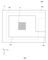
- the quartz crystal vibration element 100 according to the comparative example is similar to the quartz crystal vibration element 10 according to the first embodiment, except that the opening h1 is omitted, as shown in FIG. 8.
- k_S0 in the comparative example is 7.39%, and Fr_S0 is 985.13 MHz.
- k_A0Z in the comparative example is 0.37%, and Fr_S0 is 985.61 MHz.
- k_A0X in the comparative example is 0.12%, and Fr_S0 is 985.67 MHz.
- k_S0 is 7.39% when opening h1 is not provided, and k_S0 is 7.37% when opening h1 is provided, so the presence or absence of opening h1 has a small effect on k_S0.
- k_A0Z is reduced from 0.37% to 0.04% by providing opening h1.
- k_A0X is reduced from 0.12% to 0.00% by providing opening h1.
- the vibrations are distributed as if they are leaking from the excitation region to the first extraction electrode. This causes the vibration intensity on the first extraction electrode side in the excitation region to be stronger than the vibration intensity on the opposite side to the first extraction electrode, resulting in an imbalance in the vibration distribution.
- the vibration intensity on the first extraction electrode side in the excitation region is stronger than the vibration intensity on the opposite side to the first extraction electrode, resulting in an imbalance in the vibration distribution.
- there is no leakage of vibration to the first extraction electrode there is no leakage of vibration to the first extraction electrode, and the balance of the vibration distribution within the excitation region is improved.
- the vibrations are distributed as if they are leaking from the excitation region to the first extraction electrode. This is thought to be because the vibrations excited between the first extraction electrode and the second excitation electrode combine with the vibrations excited between the first excitation electrode and the second excitation electrode.
- the antisymmetric A0 mode is not excited because the positive and negative charges are offset in an ideal state, but when the balance of the vibration distribution is lost as in the comparative example, the amount that is not offset is emphasized.
- the opening h1 suppresses the coupling between the A0 mode in the excitation region and the vibration excited by the first extraction electrode. This improves the balance of the vibration distribution of the A0 mode in the excitation region, and the vibration distribution of the A0 mode approaches the ideal state. Therefore, the positive and negative charges in the A0 mode are offset, and the increase in k_A0Z and k_A0X caused by the first extraction electrode is suppressed.
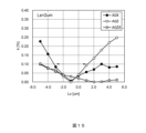
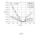
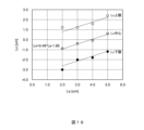
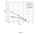
- FIGS. 12 and 13 are graphs showing the simulation results based on the first embodiment.
- the horizontal axis indicates the length Ls [ ⁇ m] of the narrow passage portion along the X-axis direction
- the vertical axis indicates the electromechanical coupling coefficient k [%].
- the horizontal axis indicates the length Ws [ ⁇ m] of the narrow passage portion along the Z'-axis direction
- the vertical axis indicates the electromechanical coupling coefficient k [%].
- the simulation conditions at this time are the same as the simulation conditions for vibration distribution based on the first embodiment, except that Ls and Ws are variables.
- k_A0ZX is the electromechanical coupling coefficient k of the spurious A0 mode in which vibrations of opposite phase are aligned in the Z'-axis and Z-axis directions.
- k_A0ZX is small over the entire range of the horizontal axis of the graphs shown in Figures 12 and 13, so a description of k_A0ZX will be omitted.
- the shorter the length Ws the smaller both k_A0X and k_A0Z become.
- the length Ws is 16 ⁇ m or less, i.e., when Ws/We ⁇ 0.20, k_A0X becomes sufficiently small.
- the length Ws is 12 ⁇ m or less, i.e., when Ws/We ⁇ 0.15, both k_A0X and k_A0Z become sufficiently small.
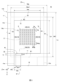
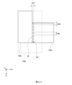
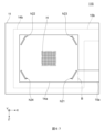
- the quartz vibration element 10 comprises a quartz blank 11, a first electrode including a first excitation electrode 14a and a first extraction electrode 15a provided on a first main surface 11A of the quartz blank 11, and a second electrode including a second excitation electrode 14b and a second extraction electrode 15b provided on a second main surface 11B of the quartz blank 11.
- a high sound velocity region 17 is provided in the center of an excitation region 19 where the first excitation electrode 14a and the second excitation electrode 14b overlap, and a low sound velocity region 18 is provided in the periphery of the excitation region 19, and a plurality of holes H are provided in the first excitation electrode 14a of the high sound velocity region 17 to increase the sound velocity.
- the outer periphery 71-74 of the first excitation electrode 14a is provided inside the outer periphery 81-84 of the second excitation electrode 14b, and the connection portion between the first excitation electrode 14a and the first extraction electrode 15a overlaps with the second excitation electrode 14b.
- An opening h1 is provided at the connection portion between the first excitation electrode 14a and the first extraction electrode 15a, and the opening h1 is substantially provided within a distance range of four times or less than the thickness Tq of the crystal piece 11 from the boundary B between the first excitation electrode 14a and the first extraction electrode 15a.
- the length Wh1 of the opening h1 in the Z'-axis direction along the boundary B is 50% or more and 90% or less of the length Wc of the first extraction electrode 15a in the Z'-axis direction along the boundary B (0.50 ⁇ Wh1/Wc ⁇ 0.90).
- Wh1/Wc 0.50 ⁇ Wh1/Wc it is possible to effectively suppress the coupling between the vibration excited between the first extraction electrode 15a and the second excitation electrode 14b and the vibration excited in the excitation region 19.
- Wh1/Wc ⁇ 0.90 it is possible to suppress the decrease in the Q value caused by the increase in resonance resistance due to the increase in wiring resistance.
- the relationship 2 ⁇ Lh1/Tq ⁇ Wh1/Tq holds for the thickness Tq of the quartz crystal piece 11, the length Wh1 of the opening h1 in the Z'-axis direction along the boundary B, and the length Lh1 of the opening h1 in the X-axis direction intersecting the boundary B.
- the opening h1 can effectively suppress coupling between the vibration excited between the first extraction electrode 15a and the second excitation electrode 14b and the vibration excited in the excitation area 19.
- the length Lh1 of the opening h1 in the X-axis direction intersecting with the boundary B is three times or more the thickness Tq of the quartz crystal piece 11 (3 ⁇ Lh1/Tq).
- the opening h1 can more effectively suppress coupling between the vibration excited between the first extraction electrode 15a and the second excitation electrode 14b and the vibration excited in the excitation region 19.
- the difference Ws between the length Wc of the first extraction electrode 15a in the Z'-axis direction along the boundary B and the length Wh1 of the opening h1 is defined as Wc, and the length We of the first excitation electrode 14a in the Z'-axis direction along the boundary B satisfies the relationship 0.05 ⁇ Ws/We ⁇ 0.15.
- Ws/We 0.05 ⁇ Ws/We it is possible to suppress the decrease in the Q value caused by the increase in resonance resistance due to the increase in wiring resistance.
- Ws/We ⁇ 0.15 it is possible to effectively suppress the coupling between the vibration excited between the first extraction electrode 15a and the second excitation electrode 14b and the vibration excited in the excitation region 19.
- k_A0Z becomes sufficiently small.
- k_A0X becomes sufficiently small. Therefore, when the relationship -2.0 ⁇ m ⁇ Lx ⁇ 1.5 ⁇ m holds, both k_A0X and k_A0Z become sufficiently small.
- Lx 0 ⁇ m, both k_A0X and k_A0Z are minimum.
- k_A0Z becomes sufficiently small.
- k_A0X becomes sufficiently small. Therefore, when the relationship -1.0 ⁇ m ⁇ Lx ⁇ 2.5 ⁇ m holds, both k_A0X and k_A0Z become sufficiently small.
- Lx 0 ⁇ m, both k_A0X and k_A0Z are minimum.
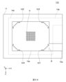
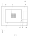
- Fig. 20 is a plan view of the quartz crystal vibrating element according to the third embodiment.
- the quartz crystal vibration element 103 has two openings h11 and h12.
- the planar shapes of the openings h11 and h12 are both rectangular slits.
- the opening h11 is provided along the boundary B.
- the opening h12 is provided on the positive X-axis side of the opening h11.
- the longitudinal direction of the opening h11 and the longitudinal direction of the opening h12 extend parallel to each other.
- the length Ls of the opening h11 along the X-axis direction is the same as the length Ls of the opening h12 along the X-axis direction.
- the opening h11 is a notch that opens on the negative Z'-axis side of the first extraction electrode 15a.
- the opening h12 is a notch that opens on the positive Z'-axis side of the first extraction electrode 15a.
- a portion of each of the openings h11 and h12 is aligned in the X-axis direction.
- FIGS. 21 to 23 are diagrams showing vibration distributions of a quartz crystal vibration element according to the third embodiment.
- FIG. 21 shows the vibration distribution of the main mode, S0 mode, as a result of a simulation based on the third embodiment.
- FIG. 22 shows the vibration distribution of the A0Z mode, as a result of a simulation based on the third embodiment.
- FIG. 23 shows the vibration distribution of the A0X mode, as a result of a simulation based on the third embodiment.
- the first excitation electrode 14a and the first extraction electrode 15a are shown, and the second excitation electrode 14b and the second extraction electrode 15b are omitted.
- k_S0 is 7.29% and Fr_S0 is 985.20 MHz.
- k_A0Z is 0.18% and Fr_A0Z is 985.73 MHz.
- k_A0X is 0.15% and Fr_A0X is 985.72 MHz.
- k_S0 increases, k_A0Z decreases, and k_A0X remains almost unchanged. Therefore, in the quartz crystal vibration element 103 of the third embodiment, the electromechanical coupling coefficient k is improved, although not as much as in the quartz crystal vibration element 10 of the first embodiment.
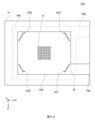
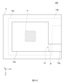
- Fig. 24 is a plan view of the quartz crystal vibrating element according to the fourth embodiment.
- the quartz crystal vibration element 104 has two openings h11 and h12.
- the openings h11 and h12 have the same planar shape of a rectangular slit and the same dimensions.
- the opening h11 is provided along the boundary B.
- the opening h12 is provided on the positive X-axis side of the opening h11.
- the longitudinal direction of the opening h11 and the longitudinal direction of the opening h12 extend parallel to each other. Both openings h11 and h12 are notch-shaped and open to the negative Z'-axis side of the first extraction electrode 15a.
- FIGS. 25 to 27 are diagrams showing vibration distributions of a quartz crystal vibration element according to the fourth embodiment.
- FIG. 25 shows the vibration distribution of the main mode, S0 mode, as a result of a simulation based on the fourth embodiment.
- FIG. 26 shows the vibration distribution of the A0Z mode, as a result of a simulation based on the fourth embodiment.
- FIG. 27 shows the vibration distribution of the A0X mode, as a result of a simulation based on the fourth embodiment.
- the first excitation electrode 14a and the first extraction electrode 15a are shown, and the second excitation electrode 14b and the second extraction electrode 15b are omitted.
- k_S0 is 7.29% and Fr_S0 is 985.21 MHz.
- k_A0Z is 0.03% and Fr_A0Z is 985.75 MHz.
- k_A0X is 0.06% and Fr_A0X is 985.72 MHz.
- the electromechanical coupling coefficient k is improved more than in the quartz crystal vibration element 103 of the third embodiment.
- the electromechanical coupling coefficient k can be improved more effectively by providing the two openings on the same side of the positive or negative Z' axis direction, rather than providing the two openings alternately on both the positive and negative Z' axis directions.
- Fig. 28 is a plan view of the quartz crystal vibrating element according to the fifth embodiment.
- the quartz crystal vibration element 105 has a plurality of openings h11.
- the planar shape of each of the plurality of openings h11 is the same rectangular slit shape, and the dimensions are also the same. All of the plurality of openings h11 are notches that open to the negative Z'-axis side of the first extraction electrode 15a.
- the plurality of openings h11 have their elongated direction in the Z'-axis direction along the boundary B, and are aligned in the X-axis direction that intersects with the boundary B.
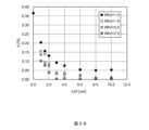
- FIG. 29 is a graph showing the simulation results based on the fifth embodiment.
- the horizontal axis indicates the total value Ls_total of the length Ls of the multiple openings h11, and the vertical axis indicates the electromechanical coupling coefficient k (k_A0Z) [%] of the A0Z mode.
- Ls 0.5 ⁇ m to 2.0 ⁇ m, in the range of 0 ⁇ m to 5.0 ⁇ m, the larger the total value of the lengths Ls, the smaller the electromechanical coupling coefficient k. From the viewpoint of reducing k_A0Z, it is preferable that 1.5 ⁇ m ⁇ Ls_total, more preferably 3.0 ⁇ m ⁇ Ls_total, and more preferably 4.5 ⁇ m ⁇ Ls_total. In other words, it is preferable that the total value Ls_total of the lengths Ls is equal to or greater than the thickness Tq of the crystal piece 11, more preferably equal to or greater than twice Tq, and even more preferably equal to or greater than three times Tq.
- k_A0Z will be sufficiently small.
- Ls 1.5 ⁇ m or 2.0 ⁇ m
- k_A0Z shows the same tendency when there are multiple openings h11 and when there is one opening h11.
- Ls 0.5 ⁇ m or 1.0 ⁇ m
- k_A0Z when there are multiple openings h11 is larger than k_A0Z when there is one opening h11.
- the suppression effect of the A0 mode decreases when Ls ⁇ 1.5 ⁇ m. Therefore, when there are multiple openings h11, it is desirable for the relationship 1.5 ⁇ m ⁇ Ls to hold.
- Fig. 30 is a plan view of the quartz crystal vibrating element according to the sixth embodiment.
- the length along the Z'-axis direction of the first excitation electrode 14a and the second excitation electrode 14b of the quartz crystal vibration element 106 according to the sixth embodiment is smaller than the length along the Z'-axis direction of the first excitation electrode 14a and the second excitation electrode 14b of the quartz crystal vibration element 101 according to the first embodiment.
- the aspect ratio of the first excitation electrode 14a and the second excitation electrode 14b of the quartz crystal vibration element 106 according to the sixth embodiment is larger than the aspect ratio of the first excitation electrode 14a and the second excitation electrode 14b of the quartz crystal vibration element 101 according to the first embodiment.
- Figs. 31 and 32 are graphs showing the simulation results based on the sixth embodiment.
- the horizontal axis indicates the length Ls [ ⁇ m] of the narrow passage portion along the X-axis direction
- the vertical axis indicates the electromechanical coupling coefficient k [%].
- the horizontal axis indicates the length Ws [ ⁇ m] of the narrow passage portion along the Z'-axis direction
- the vertical axis indicates the electromechanical coupling coefficient k [%].
- both k_A0X and k_A0Z become sufficiently small.
- the length Ws is 9 ⁇ m or less, i.e., when Ws/We ⁇ 0.15, both k_A0X and k_A0Z become sufficiently small.
- the conditions for the lengths Ls and Ws that result in a good electromechanical coupling coefficient k are the same.
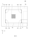
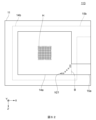
- Fig. 33 is a plan view of the quartz crystal vibrating element according to the seventh embodiment.
- Fig. 34 is an enlarged plan view of a connection portion in the seventh embodiment.
- a row of openings h2 aligned in a direction along the boundary B is provided on the first extraction electrode 15a side of the boundary B between the first excitation electrode 14a and the first extraction electrode 15a.
- the multiple openings h2 are arranged at equal intervals from the end of the first extraction electrode 15a on the positive Z'-axis side to the end on the negative Z'-axis side.
- the planar shape of the openings h2 is rectangular having a pair of sides extending along the Z'-axis direction and a pair of sides extending along the X-axis direction. One side of the openings h2 overlaps with the boundary B.
- the dimension of the opening h2 along the X-axis direction is defined as length Lh2.
- Length Lh2 is the length of the opening h2 along the direction in which the openings h2 are arranged, and is specified, for example, as the length of the opening h2 in a direction parallel to the direction in which the openings h2 are arranged.
- Length Wh2 is the dimension of the opening h2 along the Z'-axis direction.
- Length Wh2 is the length of the opening h2 along a direction intersecting the direction in which the openings h2 are arranged, and is specified, for example, as the length of the opening h2 in a direction perpendicular to the direction in which the openings h2 are arranged.
- the arrangement period of the openings h2 in the Z'-axis direction is defined as Wp.
- the arrangement period Wp is the arrangement period of the openings h2 along the direction in which the openings h2 are arranged, and is specified, for example, as the arrangement period of the openings h2 in the direction in which the openings h2 are arranged.
- FIGS. 35 to 37 are diagrams showing vibration distributions of a quartz crystal vibration element according to the seventh embodiment.
- FIG. 35 shows the vibration distribution of the S0 mode as a result of a simulation based on the seventh embodiment.
- FIG. 36 shows the vibration distribution of the A0Z mode as a result of a simulation based on the seventh embodiment.
- FIG. 37 shows the vibration distribution of the A0X mode as a result of a simulation based on the seventh embodiment.
- the first excitation electrode 14a and the first extraction electrode 15a are shown, and the second excitation electrode 14b and the second extraction electrode 15b are omitted.
- Figures 38 and 39 are graphs showing the results of a simulation based on the seventh embodiment.
- the horizontal axis shows the length Lh2 [ ⁇ m] of the opening h2 along the X-axis direction
- the vertical axis shows k_A0Z [%].
- the horizontal axis shows the ratio Wh2/Wp of the length Lh2 of the opening h2 along the Z'-axis direction to the array period Wp of the openings h2 (hereinafter referred to as the opening ratio), and the vertical axis shows k_A0Z [%].
- the row of openings h2 is provided on the first excitation electrode 14a side of the boundary B.
- the dimension from the boundary B to the end of the openings h2 on the negative X-axis side is the distance Lx.
- k_S0 in the example of the eighth embodiment is substantially the same as k_S0 in the comparative example.
- k_A0Z and Fr_A0X in the example of the eighth embodiment are smaller than k_A0Z and Fr_A0X in the comparative example.
Landscapes
- Physics & Mathematics (AREA)
- Acoustics & Sound (AREA)
- Piezo-Electric Or Mechanical Vibrators, Or Delay Or Filter Circuits (AREA)
Priority Applications (4)
| Application Number | Priority Date | Filing Date | Title |
|---|---|---|---|
| JP2025502442A JP7773705B1 (ja) | 2023-12-26 | 2024-07-12 | 圧電振動素子 |
| CN202480004546.6A CN120548673A (zh) | 2023-12-26 | 2024-07-12 | 压电振动元件 |
| US19/184,081 US20250247072A1 (en) | 2023-12-26 | 2025-04-21 | Piezoelectric resonator |
| JP2025188268A JP2026016790A (ja) | 2023-12-26 | 2025-11-07 | 圧電振動素子 |
Applications Claiming Priority (2)
| Application Number | Priority Date | Filing Date | Title |
|---|---|---|---|
| JP2023219822 | 2023-12-26 | ||
| JP2023-219822 | 2023-12-26 |
Related Child Applications (1)
| Application Number | Title | Priority Date | Filing Date |
|---|---|---|---|
| US19/184,081 Continuation US20250247072A1 (en) | 2023-12-26 | 2025-04-21 | Piezoelectric resonator |
Publications (1)
| Publication Number | Publication Date |
|---|---|
| WO2025141919A1 true WO2025141919A1 (ja) | 2025-07-03 |
Family
ID=96217236
Family Applications (1)
| Application Number | Title | Priority Date | Filing Date |
|---|---|---|---|
| PCT/JP2024/025226 Pending WO2025141919A1 (ja) | 2023-12-26 | 2024-07-12 | 圧電振動素子 |
Country Status (4)
| Country | Link |
|---|---|
| US (1) | US20250247072A1 (https=) |
| JP (2) | JP7773705B1 (https=) |
| CN (1) | CN120548673A (https=) |
| WO (1) | WO2025141919A1 (https=) |
Citations (10)
| Publication number | Priority date | Publication date | Assignee | Title |
|---|---|---|---|---|
| JPH0210907A (ja) * | 1988-06-28 | 1990-01-16 | Matsushima Kogyo Co Ltd | At振動子の周波数調整方法 |
| JPH1098351A (ja) * | 1996-07-31 | 1998-04-14 | Daishinku Co | 圧電振動デバイス |
| JP2001257560A (ja) * | 2000-03-10 | 2001-09-21 | Toyo Commun Equip Co Ltd | 超薄板圧電振動素子の電極構造 |
| JP2003273682A (ja) * | 2002-03-15 | 2003-09-26 | Seiko Epson Corp | 圧電振動片の周波数調整方法、圧電振動片および圧電デバイス |
| JP2010081317A (ja) * | 2008-09-26 | 2010-04-08 | Nippon Dempa Kogyo Co Ltd | 水晶振動子 |
| JP2010141570A (ja) * | 2008-12-11 | 2010-06-24 | Ube Ind Ltd | 圧電薄膜音響共振器およびその製造方法 |
| JP2012074807A (ja) * | 2010-09-28 | 2012-04-12 | Seiko Epson Corp | 圧電振動素子、表面実装型圧電振動子及び表面実装型圧電発振器 |
| JP2018074344A (ja) * | 2016-10-28 | 2018-05-10 | 京セラ株式会社 | 水晶素子および水晶デバイス |
| WO2022080426A1 (ja) * | 2020-10-13 | 2022-04-21 | 株式会社村田製作所 | 水晶振動素子および水晶振動子 |
| WO2023033147A1 (ja) * | 2021-09-06 | 2023-03-09 | 株式会社村田製作所 | 弾性波装置 |
-
2024
- 2024-07-12 WO PCT/JP2024/025226 patent/WO2025141919A1/ja active Pending
- 2024-07-12 JP JP2025502442A patent/JP7773705B1/ja active Active
- 2024-07-12 CN CN202480004546.6A patent/CN120548673A/zh active Pending
-
2025
- 2025-04-21 US US19/184,081 patent/US20250247072A1/en active Pending
- 2025-11-07 JP JP2025188268A patent/JP2026016790A/ja active Pending
Patent Citations (10)
| Publication number | Priority date | Publication date | Assignee | Title |
|---|---|---|---|---|
| JPH0210907A (ja) * | 1988-06-28 | 1990-01-16 | Matsushima Kogyo Co Ltd | At振動子の周波数調整方法 |
| JPH1098351A (ja) * | 1996-07-31 | 1998-04-14 | Daishinku Co | 圧電振動デバイス |
| JP2001257560A (ja) * | 2000-03-10 | 2001-09-21 | Toyo Commun Equip Co Ltd | 超薄板圧電振動素子の電極構造 |
| JP2003273682A (ja) * | 2002-03-15 | 2003-09-26 | Seiko Epson Corp | 圧電振動片の周波数調整方法、圧電振動片および圧電デバイス |
| JP2010081317A (ja) * | 2008-09-26 | 2010-04-08 | Nippon Dempa Kogyo Co Ltd | 水晶振動子 |
| JP2010141570A (ja) * | 2008-12-11 | 2010-06-24 | Ube Ind Ltd | 圧電薄膜音響共振器およびその製造方法 |
| JP2012074807A (ja) * | 2010-09-28 | 2012-04-12 | Seiko Epson Corp | 圧電振動素子、表面実装型圧電振動子及び表面実装型圧電発振器 |
| JP2018074344A (ja) * | 2016-10-28 | 2018-05-10 | 京セラ株式会社 | 水晶素子および水晶デバイス |
| WO2022080426A1 (ja) * | 2020-10-13 | 2022-04-21 | 株式会社村田製作所 | 水晶振動素子および水晶振動子 |
| WO2023033147A1 (ja) * | 2021-09-06 | 2023-03-09 | 株式会社村田製作所 | 弾性波装置 |
Also Published As
| Publication number | Publication date |
|---|---|
| JP2026016790A (ja) | 2026-02-03 |
| CN120548673A (zh) | 2025-08-26 |
| JP7773705B1 (ja) | 2025-11-20 |
| US20250247072A1 (en) | 2025-07-31 |
| JPWO2025141919A1 (https=) | 2025-07-03 |
Similar Documents
| Publication | Publication Date | Title |
|---|---|---|
| JP3969224B2 (ja) | 圧電共振子及びそれを用いた圧電フィルタ・デュプレクサ・通信装置 | |
| EP0641073B1 (en) | Packaged piezoelectric resonator | |
| WO2017208568A1 (ja) | 共振子及び共振装置 | |
| KR100330128B1 (ko) | 압전 공진자 | |
| JP2000278080A (ja) | 圧電デバイス | |
| US6987346B2 (en) | Energy trap type piezoelectric resonator component | |
| JP7773705B1 (ja) | 圧電振動素子 | |
| JP7465454B2 (ja) | 圧電振動素子、圧電振動子及び電子装置 | |
| US6333591B1 (en) | Piezoelectric resonator | |
| WO2026078949A1 (ja) | 圧電振動素子 | |
| JP7723916B2 (ja) | 圧電振動素子 | |
| JP2005033294A (ja) | 水晶振動素子 | |
| JP7606679B2 (ja) | 圧電振動素子、圧電振動子及び圧電発振器 | |
| JP7691035B1 (ja) | 圧電振動素子 | |
| US20250141426A1 (en) | Piezoelectric resonator | |
| JP7718606B2 (ja) | 圧電振動素子 | |
| US12407321B2 (en) | Quartz-crystal vibrating piece, crystal unit, crystal controlled oscillator, and intermediate wafer for quartz-crystal vibrating piece | |
| US20250357913A1 (en) | Quartz vibrating element and quartz vibrator including the same | |
| WO2025182135A1 (ja) | 圧電振動子 | |
| WO2025258357A1 (ja) | 基板及び圧電振動子 | |
| WO2025150245A1 (ja) | 圧電振動子 | |
| WO2025192111A1 (ja) | 圧電振動素子 |
Legal Events
| Date | Code | Title | Description |
|---|---|---|---|
| ENP | Entry into the national phase |
Ref document number: 2025502442 Country of ref document: JP Kind code of ref document: A |
|
| WWE | Wipo information: entry into national phase |
Ref document number: 2025502442 Country of ref document: JP |
|
| WWE | Wipo information: entry into national phase |
Ref document number: 202480004546.6 Country of ref document: CN |
|
| 121 | Ep: the epo has been informed by wipo that ep was designated in this application |
Ref document number: 24911818 Country of ref document: EP Kind code of ref document: A1 |
|
| WWP | Wipo information: published in national office |
Ref document number: 202480004546.6 Country of ref document: CN |