WO2025134875A1 - 電源装置 - Google Patents
電源装置 Download PDFInfo
- Publication number
- WO2025134875A1 WO2025134875A1 PCT/JP2024/043704 JP2024043704W WO2025134875A1 WO 2025134875 A1 WO2025134875 A1 WO 2025134875A1 JP 2024043704 W JP2024043704 W JP 2024043704W WO 2025134875 A1 WO2025134875 A1 WO 2025134875A1
- Authority
- WO
- WIPO (PCT)
- Prior art keywords
- power supply
- supply device
- cooling
- secondary battery
- battery holder
- Prior art date
- Legal status (The legal status is an assumption and is not a legal conclusion. Google has not performed a legal analysis and makes no representation as to the accuracy of the status listed.)
- Pending
Links
Images


Classifications
-
- H—ELECTRICITY
- H01—ELECTRIC ELEMENTS
- H01M—PROCESSES OR MEANS, e.g. BATTERIES, FOR THE DIRECT CONVERSION OF CHEMICAL ENERGY INTO ELECTRICAL ENERGY
- H01M10/00—Secondary cells; Manufacture thereof
- H01M10/60—Heating or cooling; Temperature control
- H01M10/61—Types of temperature control
- H01M10/613—Cooling or keeping cold
-
- H—ELECTRICITY
- H01—ELECTRIC ELEMENTS
- H01M—PROCESSES OR MEANS, e.g. BATTERIES, FOR THE DIRECT CONVERSION OF CHEMICAL ENERGY INTO ELECTRICAL ENERGY
- H01M10/00—Secondary cells; Manufacture thereof
- H01M10/60—Heating or cooling; Temperature control
- H01M10/62—Heating or cooling; Temperature control specially adapted for specific applications
- H01M10/625—Vehicles
-
- H—ELECTRICITY
- H01—ELECTRIC ELEMENTS
- H01M—PROCESSES OR MEANS, e.g. BATTERIES, FOR THE DIRECT CONVERSION OF CHEMICAL ENERGY INTO ELECTRICAL ENERGY
- H01M10/00—Secondary cells; Manufacture thereof
- H01M10/60—Heating or cooling; Temperature control
- H01M10/64—Heating or cooling; Temperature control characterised by the shape of the cells
- H01M10/643—Cylindrical cells
-
- H—ELECTRICITY
- H01—ELECTRIC ELEMENTS
- H01M—PROCESSES OR MEANS, e.g. BATTERIES, FOR THE DIRECT CONVERSION OF CHEMICAL ENERGY INTO ELECTRICAL ENERGY
- H01M10/00—Secondary cells; Manufacture thereof
- H01M10/60—Heating or cooling; Temperature control
- H01M10/65—Means for temperature control structurally associated with the cells
- H01M10/656—Means for temperature control structurally associated with the cells characterised by the type of heat-exchange fluid
- H01M10/6567—Liquids
- H01M10/6568—Liquids characterised by flow circuits, e.g. loops, located externally to the cells or cell casings
-
- H—ELECTRICITY
- H01—ELECTRIC ELEMENTS
- H01M—PROCESSES OR MEANS, e.g. BATTERIES, FOR THE DIRECT CONVERSION OF CHEMICAL ENERGY INTO ELECTRICAL ENERGY
- H01M50/00—Constructional details or processes of manufacture of the non-active parts of electrochemical cells other than fuel cells, e.g. hybrid cells
- H01M50/20—Mountings; Secondary casings or frames; Racks, modules or packs; Suspension devices; Shock absorbers; Transport or carrying devices; Holders
- H01M50/204—Racks, modules or packs for multiple batteries or multiple cells
-
- H—ELECTRICITY
- H01—ELECTRIC ELEMENTS
- H01M—PROCESSES OR MEANS, e.g. BATTERIES, FOR THE DIRECT CONVERSION OF CHEMICAL ENERGY INTO ELECTRICAL ENERGY
- H01M50/00—Constructional details or processes of manufacture of the non-active parts of electrochemical cells other than fuel cells, e.g. hybrid cells
- H01M50/20—Mountings; Secondary casings or frames; Racks, modules or packs; Suspension devices; Shock absorbers; Transport or carrying devices; Holders
- H01M50/204—Racks, modules or packs for multiple batteries or multiple cells
- H01M50/207—Racks, modules or packs for multiple batteries or multiple cells characterised by their shape
- H01M50/213—Racks, modules or packs for multiple batteries or multiple cells characterised by their shape adapted for cells having curved cross-section, e.g. round or elliptic
-
- Y—GENERAL TAGGING OF NEW TECHNOLOGICAL DEVELOPMENTS; GENERAL TAGGING OF CROSS-SECTIONAL TECHNOLOGIES SPANNING OVER SEVERAL SECTIONS OF THE IPC; TECHNICAL SUBJECTS COVERED BY FORMER USPC CROSS-REFERENCE ART COLLECTIONS [XRACs] AND DIGESTS
- Y02—TECHNOLOGIES OR APPLICATIONS FOR MITIGATION OR ADAPTATION AGAINST CLIMATE CHANGE
- Y02E—REDUCTION OF GREENHOUSE GAS [GHG] EMISSIONS, RELATED TO ENERGY GENERATION, TRANSMISSION OR DISTRIBUTION
- Y02E60/00—Enabling technologies; Technologies with a potential or indirect contribution to GHG emissions mitigation
- Y02E60/10—Energy storage using batteries
Definitions
- This disclosure relates to a power supply device.
- Power supply devices are used in which multiple rechargeable secondary battery cells, such as lithium-ion secondary batteries, are connected in series or parallel and housed in an exterior case to drive electrical equipment such as power tools, or to drive electrically-driven mobile objects such as vehicles and construction machinery (see, for example, Patent Document 1).
- the secondary battery cells used in such power supply devices generate heat when charged and discharged, and therefore need to be cooled.
- the amount of heat generated also tends to increase.
- the amount of heat generated by the power system components mounted on the circuit board must also be taken into consideration.
- a cooling pipe 840 for passing a medium such as cooling air may be arranged on the side of a battery block 830 composed of multiple secondary battery cells 801, and heat exchange may be performed by bringing the cooling pipe 840 into contact with the secondary battery cells 801 arranged at the end.
- One of the objectives of one embodiment of the present disclosure is to provide a power supply device that can efficiently cool secondary battery cells.
- Another objective of another embodiment is to provide a power supply device that facilitates heat exchange in cylindrical secondary battery cells.
- a power supply device includes a plurality of secondary battery cells, each having a cylindrical exterior can with each end face of the cylinder serving as a cell end face, a battery holder that houses the plurality of secondary battery cells, an exterior case that houses the battery holder, and a cooling section that is thermally coupled to a side face of the battery holder, the side face of the battery holder being curved to conform to the outer shape of the exterior can, and the cooling section being curved to conform to the shape of the side face of the battery holder.
- the cooling section is positioned to conform to the outer shape of the secondary battery cell located on the side of the battery holder, thereby increasing the contact area and enabling efficient cooling.
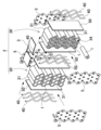
- FIG. 1 is an exploded perspective view showing a power supply device according to a first embodiment.
- FIG. FIG. 2 is an exploded perspective view of the battery module of FIG. 1 .
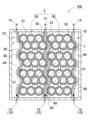
- FIG. 2 is a schematic cross-sectional view of the power supply device of FIG. 1 .
- FIG. 2 is a schematic cross-sectional view showing a power supply device according to a first comparative example.
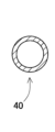
- FIG. 5A is a cross-sectional view of a cooling unit according to the first embodiment.
- FIG. 5B is a cross-sectional view of the cooling unit according to the second embodiment.
- FIG. 5C is a cross-sectional view of a cooling unit according to the third embodiment.
- FIG. 5D is a cross-sectional view of a cooling unit according to the fourth embodiment.
- FIG. 5A is a cross-sectional view of a cooling unit according to the first embodiment.
- FIG. 5B is a cross-sectional view of the cooling unit according to the second embodiment.
- FIG. 5C is
- FIG. 13 is a perspective view showing a battery module of a power supply device according to a fifth embodiment.
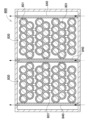
- FIG. 13 is a schematic cross-sectional view showing a power supply device according to a sixth embodiment.
- FIG. 11 is a schematic cross-sectional view showing a power supply device according to a second comparative example.
- the multiple secondary battery cells are stacked in multiple tiers in the vertical direction with the end faces of each cell on the same plane, the cell end faces of adjacent secondary battery cells in the vertical direction of the multiple tiers are offset with the center of the circle shifted, the side of the battery holder is formed in a corrugated shape in a cross-sectional view, and the cooling part is formed in a corrugated shape to follow the corrugation of the side of the battery holder.
- the cooling part is formed in a corrugated shape in the same way as the battery holder, which has corrugated sides due to the staggered arrangement, and is in contact with the battery holder over a wide area, thereby improving thermal bonding and improving heat dissipation.
- the cooling section is disposed on each side of the battery holder.
- the cooling section cools both the left and right sides of the battery holder, and the cooling of the internal secondary battery cells is performed from the left and right, thereby promoting heat dissipation.
- the battery holder includes a plurality of battery holders
- the cooling section includes a plurality of cooling sections, each of which is interposed between adjacent battery holders.
- the cooling section is formed in a tubular shape for flowing cooling gas inside.
- the power supply device in any of the above embodiments, further includes a flexible heat-conducting sheet interposed between the battery holder and the cooling section.
- a flexible heat-conducting sheet interposed between the battery holder and the cooling section.
- the power supply device disclosed herein can be used as a power source for portable electrical devices such as power tools and electric cleaners, as a driving power source for mobile objects such as electric carts, electric scooters and assisted bicycles, as a backup power source for servers in stationary power storage applications, as a power supply device for home, business and factory use, and even as a driving power source for vehicles such as hybrid cars and electric automobiles.
- portable electrical devices such as power tools and electric cleaners
- driving power source for mobile objects such as electric carts, electric scooters and assisted bicycles
- servers in stationary power storage applications as a power supply device for home, business and factory use
- a driving power source for vehicles such as hybrid cars and electric automobiles.
- FIG. 1 A power supply device 100 according to a first embodiment of the present disclosure is shown in Figures 1 to 3.
- Figure 1 shows an exploded perspective view of the power supply device 100 according to the first embodiment
- Figure 2 shows an exploded perspective view of the battery module 2 in Figure 1
- Figure 3 shows a schematic cross-sectional view of the power supply device 100 in Figure 1.
- the power supply device 100 shown in these figures includes an exterior case 10, a battery module 2, and a circuit board 3.
- the exterior case 10 houses the battery module 2 and the circuit board 3.
- the exterior case 10 may have any shape that has a storage space inside.
- the exterior case 10 has a box shape with an exterior that extends in one direction.
- the box-shaped exterior case 10 is composed of an upper case 11 and a lower case 12 that are divided into two parts, upper and lower.
- the present disclosure is not limited to this configuration, and the exterior case may be divided into three or more parts.
- the exterior case may also be divided into left and right parts.
- the divided exterior cases are waterproofed by a waterproof structure.
- the exterior case 10 is preferably made of a material with excellent insulating properties, for example a resin such as polycarbonate or PC-ABS alloy. However, the exterior case may also be made of a metal material such as aluminum or its alloy.
- An internal space is provided inside the exterior case 10 to house the battery module 2 and circuit board 3. In the example shown in Figure 1, an internal space is formed in the lower case 12, and the battery module 2 and circuit board 3 are housed therein.
- the exterior case 10 has an external opening 15 in a part thereof.
- the external opening 15 is connected to a cooling air passage.
- the external openings 15 are a first external opening 13 on the bottom surface of the exterior case 10 and a second external opening 14 on the upper side of the exterior case 10.
- the battery module 2 also called a core pack, houses a plurality of secondary battery cells 1.
- the battery module 2 may also be composed of a plurality of battery blocks 30, with each battery block 30 housing a plurality of secondary battery cells 1. In the example of Fig. 2, two battery blocks 30 are stacked laterally to form the battery module 2.
- a circuit board 3 is placed around each battery block 30.
- a cooling unit 40 is arranged on each side of the battery block 30.
- Each battery block 30 includes a battery holder 31, a rechargeable battery cell 1, and a lead plate 5. As shown in Fig. 2, the battery holder 31 has multiple cylindrical holder portions 34 into which a rechargeable battery cell 1 is inserted and held.
- the battery holder 31 may store all the rechargeable battery cells 1 as a whole, or may be divided into multiple sub-holders to store some of the multiple rechargeable battery cells in each sub-holder.
- the battery holder may also be divided in the length direction of the rechargeable battery cells.
- the battery holder 31 is made of a material with excellent insulating properties. It is preferably made of a resin such as polycarbonate or PC-ABS alloy.
- the battery block 30 also includes lead plates 5 for electrically connecting the rechargeable battery cells 1 to each other.
- the lead plates 5 are preferably arranged on the outer surface side of the battery holder 31.
- the lead plates 5 are electrically connected to the terminals of the rechargeable battery cells 1 that are exposed through electrode windows opened in the battery holder 31.
- Each lead plate 5 connects the electrodes of the cell end faces of the secondary battery cells 1 to each other, connecting multiple secondary battery cells 1 together.
- the lead plate 5 is made of a metal plate with excellent conductivity, such as an aluminum plate, a nickel plate, or a copper plate.
- Multiple secondary battery cells 1 are connected in series or in parallel via the lead plate 5.
- the number of series connections and the number of parallel connections can be set as desired according to the required specifications.
- each lead plate 5 mainly connects the end faces of 10 secondary battery cells 1, and a total of 21 secondary battery cells 1 are used in one battery block 30, forming 1 series x 21 parallel.
- two battery blocks 30 are stacked in the longitudinal direction of the secondary battery cells 1, and these battery blocks 30 are connected in series, forming a total of 42 secondary battery cells 1 in 2 series x 21 parallel.
- the number of secondary battery cells and the connection form i.e., the number of series and the number of parallel connections, are not limited to this configuration.
- the battery block 30 is connected to the circuit board 3 via lead plates 5.
- the circuit board 3 is equipped with a charge/discharge circuit that charges and discharges the secondary battery cells 1, and a protection circuit that monitors the voltage and temperature of the secondary battery cells 1 and cuts off the current in the event of an abnormality.
- the circuit board 3 is made of a glass epoxy board or the like.
- a board holder may also be provided as a member for holding the circuit board 3.
- a circuit board 3 is placed on the upper surface of each battery block 30, but the present disclosure is not limited to this configuration, and a single circuit board may be connected to each battery block.
- each battery block 30 houses a secondary battery cell 1 in a battery holder 31.
- Each secondary battery cell 1 may be a secondary battery cell having a cylindrical or rectangular external shape.
- the cylindrical secondary battery cells 1 are used in an outer can arranged in a staggered manner in a horizontal position.
- the number and arrangement of the secondary battery cells 1 are not limited to this example, and any number and arrangement may be appropriately adopted.
- cylindrical secondary battery cells may be arranged in a matrix (details will be described later).
- the secondary battery cells 1 may be any known secondary battery, such as a lithium ion secondary battery, a nickel metal hydride battery, or a nickel cadmium battery.
- Each secondary battery cell 1 has a positive electrode and a negative electrode.
- the positive or negative electrode terminal is preferably provided on one cell end face of the secondary battery cell 1.
- a positive electrode terminal is provided on one cell end face of the secondary battery cell 1, and the other face of the outer can serves as the negative electrode.
- the battery holder 31 stacks multiple secondary battery cells 1 in multiple vertical stages with the end faces of each cell on the same plane. Furthermore, the cell end faces of adjacent secondary battery cells 1 in the multiple stages are offset in the vertical direction with the centers of the circles shifted. As a result, the collection of multiple secondary battery cells 1 stored in the battery block 30 is aligned flat on the top and bottom surfaces, but has an uneven shape on the side surfaces with the centers of the cell end faces shifted. For this reason, the side surfaces of the battery holder 31 are curved to follow the external shape of the exterior can of the secondary battery cells 1, as shown in Figure 3.
- a cooling unit 40 is disposed on the side of the battery holder 31.
- the cooling unit 40 is thermally coupled to the cooling unit 40 via a thermally conductive sheet 50.
- the cooling unit 40 is curved to fit the shape of the side of the battery holder 31. By arranging the cooling unit 40 in this way to fit the outer shape of the secondary battery cells 1 located on the side of the battery holder 31, the contact area is increased, making it possible to perform cooling more efficiently.
- the secondary battery cells stored inside generate heat when they are charged and discharged, and therefore need to be cooled.
- One possible cooling structure is to arrange cooling pipes 840 for flowing a refrigerant such as cooling air on the side of a battery block 30 composed of multiple secondary battery cells 801, as in the power supply device 800 according to the comparative example shown in Figure 4, and to bring the cooling pipes 840 into contact with the secondary battery cells 801 arranged at the ends to exchange heat.
- the secondary battery cells 801 are often stacked vertically in a staggered arrangement with each row offset, as shown in FIG. 4, for space efficiency reasons.
- the secondary battery cells 801 located at the ends of the battery block 830 alternate between being in contact with the cooling pipes 840 installed on the sides of the battery block 830 and not being in contact with them.
- the contact points are line contact and the contact area is small. This makes it difficult to carry out efficient heat exchange.
- the cooling section 40 is not straight, but curved to follow the side shape of the battery holder 31, thereby increasing the contact area, promoting heat exchange, and enabling efficient cooling.
- the side of the battery holder 31 is formed in a corrugated shape in a cross-sectional view.
- the side surfaces of the multiple battery holders 31 constituting each of the two battery blocks 30 face each other so that the corrugated projections and recesses of the adjacent battery holders 31 fit together.
- the cooling section 40 is disposed on the outer side surface and adjacent side surface of each of the two battery blocks 30, and is formed in a corrugated shape so as to follow the corrugation of the side surface of the battery holder 31.
- the cooling section 40 disposed between two adjacent battery blocks 30 is shared by the two battery blocks 30. This ensures the density of the multiple secondary battery cells 1, and the cooling section 40 is formed in a similar corrugated shape to the battery holder 31, whose sides are corrugated due to the staggered arrangement, and the cooling section 40 is brought into contact over a wide area, improving thermal coupling and improving heat dissipation.
- the contact area is made larger, allowing for more efficient air cooling.
- the cooling section 40 can also cool not only the heat generated by the secondary battery cells 1 housed in the battery holder 31, but also the heat generating components mounted on the circuit board 3 placed on the battery holder 31, such as power semiconductors.
- the cooling section 40 is connected to the external opening 15 formed in the exterior case 10. Specifically, as shown in FIG. 3, the first external opening 13, which opens on the bottom surface of the exterior case 10 as the external opening 15, is connected to the lower end of the cooling section 40, and the second external opening 14, which opens on the upper side of the exterior case 10, is connected to the upper end of the cooling section 40.
- the air taken into the exterior case 10 through the external opening 15 is used as a cooling medium and is air-cooled by heat exchange in the cooling section 40.
- a fan or the like may be provided to forcibly flow the cooling air. Note that in this disclosure, an example is described in which cooling air is taken in from the first external opening 13 and discharged from the second external opening 14 as shown in FIG. 3, but this configuration is not limited to this, and it goes without saying that the cooling air may be taken in from the second external opening and discharged from the first external opening.
- the cooling unit 40 may be placed on only one side of the battery holder 31, but preferably, as shown in FIG. 3 etc., multiple cooling units 40 are used and placed on both sides of the battery holder 31. This allows the cooling units 40 to cool both the left and right sides of the battery holder 31, and the cooling of the internal secondary battery cells 1 from both the left and right promotes heat dissipation.
- the battery module 2 includes multiple battery holders 31.
- the cooling sections 40 are not only on the sides of the battery module 2 but also in between the multiple secondary battery cells 1, the secondary battery cells 1 that are located in the middle and prone to trapping heat can be directly cooled by the additional cooling section 40, making it possible to achieve even more efficient cooling.
- the cooling section 40 is made of a metal with excellent electrical conductivity.
- the cooling section 40 is formed into a hollow tube. By flowing a refrigerant such as a cooling gas inside this tube, heat exchange can be achieved with an air-cooled cooling pipe.
- a refrigerant such as a cooling gas inside this tube.
- multiple cooling pipes are arranged at a distance from each other on the side surface of each battery holder 31.
- Each cooling pipe is deformed into a corrugated shape to fit the curved surface of the battery holder 31. This type of configuration can be achieved relatively easily.
- the cross-sectional shape of the cooling pipe can be other than circular as shown in FIG. 5A.
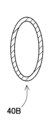
- the cooling section 40B of the power supply device according to embodiment 2 shown in FIG. 5B is a flat pipe with an elliptical cross-sectional shape. This allows the contact area with the battery holder 31 to be increased compared to a circular shape.
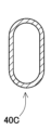
- the cross-sectional shape of the cooling section 40C is a track shape. This allows the contact area with the battery holder 31 to be further increased.
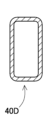
- the cross-sectional shape of the cooling section 40D may be rectangular as in the power supply device according to embodiment 4 shown in FIG. 5D. This allows the contact area with the battery holder 31 to be further increased.
- the rectangular cooling section has a rectangular shape with the contact surface with the cooling pipe as the long side. It is also preferable to chamfer the corners.
- the cross-sectional shape is not limited to a square shape, and can also be a polygonal shape such as a triangle.
- thermally conductive sheet 50 with excellent thermal conductivity can be interposed between the battery holder 31 and the cooling unit 40.
- the thermally conductive sheet 50 is flexible. By interposing the flexible thermally conductive sheet 50 between the side surface of the battery holder 31 and the cooling unit 40 in this manner, the gap at the bonding interface between them is reduced, preventing the formation of an insulating layer of air and improving thermal bonding.
- the thermally conductive sheet 50 can be, for example, a 1 mm to 3 mm elastically deformable cushion sheet with excellent thermal conductivity.
- the thermally conductive sheet 50 is sandwiched between the battery holder 31 and the cooling unit 40 in a crushed state and is in close contact with the battery holder 31 and the cooling unit 40. This reduces the formation of a heat insulating layer due to the occurrence of gaps, and brings the battery holder 31 and the cooling unit 40 into close thermal contact, allowing the secondary battery cells 1 to dissipate heat efficiently.
- the thermally conductive sheet 50 is in the form of a sheet that covers the entire side surface of the battery holder 31, but this is not limited to the configuration, and it may be configured to cover only the area where the cooling section contacts the battery holder.
- the thermally conductive sheet may be formed in the form of multiple strips.
- the power supply device 100 is configured to cool each battery block 30 from both sides by the cooling air flowing through the cooling unit 40 inside the exterior case 10.
- the inlets and outlets of the cooling air flowing through the cooling unit 40 are joined to the first external opening 13 opened on the bottom surface of the exterior case 10 and the second external opening 14 opened on the top surface of the exterior case 10.
- the gap between the first external opening 13 and the inlet and outlet of the cooling unit 40, and the gap between the second external opening 14 and the inlet and outlet of the cooling unit 40 are each liquid-tightly sealed by a sealant, and the joint surface between the upper case 11 and the lower case 12 constituting the exterior case 10 is also liquid-tightly sealed by a sealant, so that the exterior case 10 is configured to have a waterproof structure. Therefore, it is possible to prevent water from entering each battery block 30 of the exterior case 10 through the openings of the first external opening 13 and the second external opening 14 provided in the exterior case 10, or the gaps in the joint surface between the upper case 11 and the lower case 12.
- a tubular cooling pipe is used as the cooling unit 40, but the present disclosure does not limit the cooling unit 40 to a tubular shape, and the cooling unit 40 may be plate-shaped.
- the cooling unit 40 may be configured to flow cooling air inside a hollow plate.
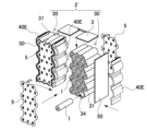
- FIG. 6 Such an example is shown in the perspective view of FIG. 6 as a power supply device according to embodiment 5, and its battery module 2'.
- the same components as those in embodiment 1 and the like are given the same reference numerals, and detailed descriptions are omitted as appropriate.
- the cooling section 40E arranged on the side of the battery module 2' shown in Figure 6 is formed in the shape of a hollow corrugated plate.
- the plate is made of a highly conductive material such as metal, and is open at the top and bottom. With this type of cooling section 40E, a single member can cool the entire side of the battery holder 31 over a wide area.
- the power supply device is attached to the electrical device to be driven and supplies power to the electrical device.
- the power supply device can be replaced to continue using the electrical device.
- the present invention is not limited to power supply devices of a replaceable type that mainly houses secondary battery cells, but can also be applied to configurations in which secondary battery cells are housed within the housing of electrical device.
- a power supply device is sufficient as long as it houses secondary battery cells in a case, and also includes power supply devices that have secondary battery cells built in for driving the electrical device itself within the housing.
- the present invention is not limited to replaceable power supply devices, but can also be applied to electrical devices that have built-in secondary battery cells.
- the power supply device can be suitably used as a power source for driving assisted bicycles, self-propelled robots for home delivery, electric carts for home delivery and golf courses, electric scooters, construction machinery, hybrid cars, electric cars, and other vehicles. It can also be used as a power source for portable electrical devices such as walkie-talkies, electric cleaners, and power tools. It can also be used as a cooling mechanism for electrical devices with built-in heating elements, and is not limited to being a power source. It can also be used as a stationary power storage device, for example, a power supply device for home, business, or factory use, or as a backup power source for servers, etc.
Landscapes
- Chemical & Material Sciences (AREA)
- Chemical Kinetics & Catalysis (AREA)
- Electrochemistry (AREA)
- General Chemical & Material Sciences (AREA)
- Engineering & Computer Science (AREA)
- Manufacturing & Machinery (AREA)
- Secondary Cells (AREA)
- Battery Mounting, Suspending (AREA)
Abstract
電源装置は、それぞれが外装缶を円筒状とし、該円筒状の各端面をそれぞれセル端面とする複数の二次電池セルと、複数の二次電池セルを収納する電池ホルダと、電池ホルダを収納する外装ケースと、電池ホルダの側面と熱結合された冷却部とを備える。電池ホルダは、その側面を、外装缶の外形に沿って湾曲させており、冷却部は、電池ホルダの側面の形状に沿って、湾曲されている。このように電池ホルダの側面に位置する二次電池セルの外形に沿うように冷却部を配置することで、接触面積を増して効率良く冷却を行うことが可能となる。
Description
本開示は、電源装置に関する。
リチウムイオン二次電池等の充電可能な二次電池セルを複数、直列や並列に接続して外装ケースに収納し、電動工具等の電気機器を駆動させたり、車両や建機などの電動移動体を駆動させたりする用途で、電源装置が利用されている(例えば特許文献1)。このような電源装置で用いる二次電池セルは、充放電によって発熱するため、冷却する必要がある。特に近年においては電源装置の高出力化、高容量化が求められており、使用する二次電池セルの高容量化が進められた結果、発熱量も高くなる傾向にある。また二次電池セル以外に、回路基板に実装されたパワー系実装部品の発熱量も考慮する必要がある。
このような熱対策として、図4に示すように複数の二次電池セル801で構成された電池ブロック830の側面に、冷却空気等の媒体を流すための冷却パイプ840を配置して、端部に配置された二次電池セル801と接触させることにより熱交換を行うことが考えられる。
しかしながら、円筒型の二次電池セル801を複数積層する構成においては、スペース効率を考えて図4に示すように行毎にオフセットさせた千鳥状に配置されることが多い。この結果、電池ブロック830の端部に位置する二次電池セル801は、電池ブロック830の側面に設置された冷却パイプ840と、接触するものと接触しないものとが交互に表れることとなる。また、冷却パイプ840と接触する二次電池セル801についても、二次電池セル801が円筒状であるため、接触箇所は線接触となり、接触面積が少ない。このため、効率的な熱交換を行い難い状況となっていた。
本開示の一形態の目的の一は、二次電池セルを効率良く冷却できるようにした電源装置を提供することにある。また他の形態の目的の一は、円筒状の二次電池セルの熱交換を行いやすくした電源装置を提供することにある。なお、本開示のこれらの目的や課題の記載は、他の目的や課題の存在を妨げるものではない。また本開示の一態様は、これらの課題の全てを解決する必要はないものとする。さらに本開示の明細書、図面、請求項の記載から、これら以外の課題を抽出することが可能である。
本開示の一形態に係る電源装置は、それぞれが外装缶を円筒状とし、該円筒状の各端面をそれぞれセル端面とする複数の二次電池セルと、前記複数の二次電池セルを収納する電池ホルダと、前記電池ホルダを収納する外装ケースと、前記電池ホルダの側面と熱結合された冷却部と、を備える電源装置であって、前記電池ホルダは、その側面を、前記外装缶の外形に沿って湾曲させており、前記冷却部は、前記電池ホルダの側面の形状に沿って、湾曲されている。
本開示の一形態に係る電源装置によれば、電池ホルダの側面に位置する二次電池セルの外形に沿うように冷却部を配置することで、接触面積を増して効率良く冷却を行うことが可能となる。
本開示の形態は、以下の構成や特徴によって特定されてもよい。
本開示の他の形態に係る電源装置は、上記形態において、前記複数の二次電池セルは、該複数の二次電池セルを、各セル端面が同一平面状となる姿勢で、上下方向に複数段に積層しており、該複数段の上下方向において隣接する二次電池セルの前記セル端面が、円形の中心をずらしたオフセット配置されており、前記電池ホルダの側面が、断面視において波形に形成されており、前記冷却部は、前記電池ホルダの側面の波形に沿うように、波形に形成されている。上記構成により、千鳥配置によって側面が波形となった電池ホルダに対して、冷却部を同様に波形に形成して、広い面積で接触させることにより熱結合性を向上させ、放熱性を改善できる利点が得られる。
また本開示の他の形態に係る電源装置は、上記いずれかの形態において、前記冷却部が、前記電池ホルダの両側の側面にそれぞれ配置されている。上記構成により、電池ホルダの左右の両面から冷却部で冷却して、内部の二次電池セルの冷却を左右から行うことで放熱を促進することができる。
さらに本開示の他の形態に係る電源装置は、上記いずれかの形態において、前記電池ホルダが、複数の電池ホルダを備えており、前記冷却部が、複数の冷却部を備えており、隣接する電池ホルダ同士の間に、それぞれ前記冷却部を介在させている。上記構成により、電池ホルダの側面のみならず、複数の二次電池セルの中間にも冷却部を配置して、中間に配置されて熱が籠もりやすい二次電池セルを、追加の冷却部で直接冷却することにより、さらに効率良く冷却を図ることが可能となる。
さらにまた本開示の他の形態に係る電源装置は、上記いずれかの形態において、前記冷却部が、内部に冷却気体を流すための管状に形成されている。上記構成により、空冷式の冷却管を電池ホルダの曲面に沿うように接触させて、効率良く熱交換を行うことが可能となる。
さらにまた本開示の他の形態に係る電源装置は、上記いずれかの形態において、さらに、前記電池ホルダと前記冷却部との間に介在される、可撓性を有する熱伝導シートを備えている。上記構成により、可撓性を有する熱伝導シートを電池ホルダの側面と冷却部との間に介在させることで、隙間をなくして接合界面における断熱層が形成される事態を抑制できる。
以下、本開示の実施形態を図面に基づいて説明する。ただし、以下に示す実施形態は、本開示の技術思想を具体化するための例示であって、本開示は以下のものに特定されない。また、本明細書は特許請求の範囲に示される部材を、実施形態の部材に特定するものでは決してない。特に実施形態に記載されている構成部品の寸法、材質、形状、その相対的配置等は特に特定的な記載がない限りは、本開示の範囲をそれのみに限定する趣旨ではなく、単なる説明例にすぎない。なお、各図面が示す部材の大きさや位置関係等は、説明を明確にするため誇張していることがある。さらに以下の説明において、同一の名称、符号については同一若しくは同質の部材を示しており、詳細説明を適宜省略する。さらに、本開示を構成する各要素は、複数の要素を同一の部材で構成して一の部材で複数の要素を兼用する態様としてもよいし、逆に一の部材の機能を複数の部材で分担して実現することもできる。
本開示の電源装置は、電動工具や電動クリーナ等の携帯型電気機器の電源として、また電動カートや電動スクータ、アシスト自転車などの移動体用の駆動用電源として、あるいは据え置き型の蓄電用途でサーバのバックアップ用電源や家庭用、事業所用、工場用の電源装置として、さらにはハイブリッド車や電気自動車等の車両の駆動用電源等に利用できる。以下、本発明の一実施形態として、電動工具用の駆動電源として用いる電源装置について説明する。
[実施形態1]
本開示の実施形態1に係る電源装置100を図1~図3に示す。これらの図において、図1実施形態1に係る電源装置100を示す分解斜視図、図2図1の電池モジュール2の分解斜視図、図3図1の電源装置100の模式断面図を、それぞれ示している。これらの図に示す電源装置100は、外装ケース10と、電池モジュール2と、回路基板3を備えている。
本開示の実施形態1に係る電源装置100を図1~図3に示す。これらの図において、図1実施形態1に係る電源装置100を示す分解斜視図、図2図1の電池モジュール2の分解斜視図、図3図1の電源装置100の模式断面図を、それぞれ示している。これらの図に示す電源装置100は、外装ケース10と、電池モジュール2と、回路基板3を備えている。
(外装ケース10)
外装ケース10は、電池モジュール2や回路基板3を収納する。外装ケース10の外形は、内部に収納空間を有する任意の形状が利用できる。図1に示す例では、外装ケース10は外観を一方向に延長した箱形に形成している。箱形の外装ケース10は、上下に二分割された上ケース11と下ケース12で構成されている。ただ本開示はこの構成に限られず、外装ケースを三分割以上に分割してもよい。また外装ケースを左右に分割してもよい。分割された外装ケース同士は防水構造により防水されている。
外装ケース10は、電池モジュール2や回路基板3を収納する。外装ケース10の外形は、内部に収納空間を有する任意の形状が利用できる。図1に示す例では、外装ケース10は外観を一方向に延長した箱形に形成している。箱形の外装ケース10は、上下に二分割された上ケース11と下ケース12で構成されている。ただ本開示はこの構成に限られず、外装ケースを三分割以上に分割してもよい。また外装ケースを左右に分割してもよい。分割された外装ケース同士は防水構造により防水されている。
この外装ケース10は、絶縁性に優れた部材、例えばポリカーボネートやPC-ABSアロイなどの樹脂製とすることが好ましい。ただ、外装ケースをアルミニウムやその合金など、金属製部材により構成してもよい。また外装ケース10の内部には、電池モジュール2や回路基板3を収納する内部空間を設けている。図1に示す例では、下ケース12に内部空間を形成し、電池モジュール2と回路基板3を収納している。
さらに外装ケース10は、その一部に外部開口部15を開口している。外部開口部15は、冷却空気路と連通される。図1に示す例では、外部開口部15として外装ケース10の底面に外部第一開口13を開口し、外装ケース10の上側に外部第二開口14を開口している。
(電池モジュール2)
電池モジュール2は、コアパックなどとも呼ばれ、複数の二次電池セル1を収納する。また電池モジュール2を、複数の電池ブロック30で構成し、各電池ブロック30に複数の二次電池セル1を収納してもよい。図2の例では、2つの電池ブロック30を横方向に積層して電池モジュール2を構成している。各電池ブロック30の周囲には回路基板3を載置している。さらに電池ブロック30の側面には、それぞれ冷却部40を配置している。
電池モジュール2は、コアパックなどとも呼ばれ、複数の二次電池セル1を収納する。また電池モジュール2を、複数の電池ブロック30で構成し、各電池ブロック30に複数の二次電池セル1を収納してもよい。図2の例では、2つの電池ブロック30を横方向に積層して電池モジュール2を構成している。各電池ブロック30の周囲には回路基板3を載置している。さらに電池ブロック30の側面には、それぞれ冷却部40を配置している。
(電池ホルダ31)
各電池ブロック30は、電池ホルダ31と、二次電池セル1と、リード板5を備える。電池ホルダ31は、図2に示すように筒状のホルダ筒部34を複数形成しており、各ホルダ筒部34に二次電池セル1を挿入して保持する。電池ホルダ31は、一体としてすべての二次電池セル1を収納する他、複数のサブホルダに分割して、複数の二次電池セルの内、何本かをサブホルダに収納するように構成してもよい。また電池ホルダを、二次電池セルの長さ方向に分割してもよい。
各電池ブロック30は、電池ホルダ31と、二次電池セル1と、リード板5を備える。電池ホルダ31は、図2に示すように筒状のホルダ筒部34を複数形成しており、各ホルダ筒部34に二次電池セル1を挿入して保持する。電池ホルダ31は、一体としてすべての二次電池セル1を収納する他、複数のサブホルダに分割して、複数の二次電池セルの内、何本かをサブホルダに収納するように構成してもよい。また電池ホルダを、二次電池セルの長さ方向に分割してもよい。
電池ホルダ31は、絶縁性に優れた材質で構成される。好ましくは、ポリカーボネートやPC-ABSアロイなどの樹脂製とする。
(リード板5)
また電池ブロック30は、二次電池セル1同士を電気接続するためのリード板5を備えている。リード板5は、好ましくは電池ホルダ31の外面側に配置される。リード板5は、電池ホルダ31に開口された電極窓を通じて表出された二次電池セル1の端子と、電気的に接続される。
また電池ブロック30は、二次電池セル1同士を電気接続するためのリード板5を備えている。リード板5は、好ましくは電池ホルダ31の外面側に配置される。リード板5は、電池ホルダ31に開口された電極窓を通じて表出された二次電池セル1の端子と、電気的に接続される。
各リード板5は、二次電池セル1のセル端面の電極同士を接続して、複数の二次電池セル1間を接続する。リード板5は、アルミニウム板やニッケル板、銅板等の導電性に優れた金属板で構成される。複数の二次電池セル1は、リード板5を介して直列や並列に接続される。直列接続数や並列接続数は、要求される仕様に応じて任意に設定できる。図2等の例では、各リード板5で主に10本の二次電池セル1の端面を接続し、一の電池ブロック30全体で計21本の二次電池セル1を使用して1直列×21並列としている。また2つの電池ブロック30を、二次電池セル1の長手方向に積層して、これらの電池ブロック30を直列に接続しており、計42本の二次電池セル1を2直列×21並列としている。ただ、二次電池セルの本数や接続形態、すなわち直列数や並列数は、この構成に限定されるものでない。
(回路基板3)
電池ブロック30は、リード板5を介して回路基板3に接続される。回路基板3は、二次電池セル1を充放電する充放電回路や、二次電池セル1の電圧や温度を監視して異常時には電流を遮断する保護回路等を実装している。回路基板3はガラスエポキシ基板などで構成される。また回路基板3を保持する部材として、基板ホルダを配置してもよい。
電池ブロック30は、リード板5を介して回路基板3に接続される。回路基板3は、二次電池セル1を充放電する充放電回路や、二次電池セル1の電圧や温度を監視して異常時には電流を遮断する保護回路等を実装している。回路基板3はガラスエポキシ基板などで構成される。また回路基板3を保持する部材として、基板ホルダを配置してもよい。
なお図2等の例では、各電池ブロック30の上面に回路基板3をそれぞれ載置する例を示しているが、本開示はこの構成に限られず、一枚の回路基板を各電池ブロックに接続してもよい。
(二次電池セル1)
各電池ブロック30は、図2に示すように、電池ホルダ31内に二次電池セル1を収納している。各二次電池セル1は、外形が円筒型や角型の二次電池セルを利用できる。図2等に示す例では、外装缶を円筒形の二次電池セル1を横置きの姿勢で千鳥状に並べて使用している。なお、二次電池セル1の数や配置は、この例に限らず、任意の数や配置を適宜採用できる。例えば円筒形の二次電池セルをマトリックス状に並べてもよい(詳細は後述)。二次電池セル1には、リチウムイオン二次電池やニッケル水素電池、ニッケルカドミウム電池等の、既知の二次電池が適宜利用できる。
各電池ブロック30は、図2に示すように、電池ホルダ31内に二次電池セル1を収納している。各二次電池セル1は、外形が円筒型や角型の二次電池セルを利用できる。図2等に示す例では、外装缶を円筒形の二次電池セル1を横置きの姿勢で千鳥状に並べて使用している。なお、二次電池セル1の数や配置は、この例に限らず、任意の数や配置を適宜採用できる。例えば円筒形の二次電池セルをマトリックス状に並べてもよい(詳細は後述)。二次電池セル1には、リチウムイオン二次電池やニッケル水素電池、ニッケルカドミウム電池等の、既知の二次電池が適宜利用できる。
各二次電池セル1は、それぞれ正極及び負極の電極を有する。正極または負極の電極の端子は、好ましくは二次電池セル1の一方のセル端面に設けられる。図2の例では、二次電池セル1の一方のセル端面に正極端子を設け、外装缶の他の面を負極としている。
電池ホルダ31は、複数の二次電池セル1を、各セル端面が同一平面状となる姿勢で、上下方向に複数段に積層している。また複数段の上下方向において隣接する二次電池セル1のセル端面が、円形の中心をずらしたオフセット配置されている。この結果、電池ブロック30に収納される複数の二次電池セル1の集合体は、上下面においてはフラットに並ぶ一方で、側面においては各セル端面の中心がずれた凹凸状となる。このため電池ホルダ31は、図3に示すようにその側面を、二次電池セル1の外装缶の外形に沿って湾曲させている。
(冷却部40)
このような電池ホルダ31の側面には、冷却部40が配置されている。冷却部40は、熱伝導シート50を介して冷却部40と熱結合されている。冷却部40は、電池ホルダ31の側面の形状に沿って、湾曲されている。このように電池ホルダ31の側面に位置する二次電池セル1の外形に沿うように冷却部40を配置することで、接触面積を増して効率良く冷却を行うことが可能となる。
このような電池ホルダ31の側面には、冷却部40が配置されている。冷却部40は、熱伝導シート50を介して冷却部40と熱結合されている。冷却部40は、電池ホルダ31の側面の形状に沿って、湾曲されている。このように電池ホルダ31の側面に位置する二次電池セル1の外形に沿うように冷却部40を配置することで、接触面積を増して効率良く冷却を行うことが可能となる。
二次電池セルを複数用いた電源装置では、内部に収納した二次電池セルが充放電によって発熱するため、冷却する必要がある。このような冷却構造として、図4に示す比較例に係る電源装置800のように、複数の二次電池セル801で構成された電池ブロック30の側面に、冷却空気等の冷媒を流すための冷却パイプ840を配置して、端部に配置された二次電池セル801と接触させることにより熱交換を行うことが考えられる。
円筒型の二次電池セル1を複数積層した電池ブロック830においては、スペース効率を考えて図4に示すように二次電池セル801を上下方向に積層する際に、行毎にオフセットさせた千鳥状に配置されることが多い。この結果、電池ブロック830の端部に位置する二次電池セル801は、電池ブロック830の側面に設置された冷却パイプ840と、接触するものと接触しないものとが交互に表れることとなる。また、冷却パイプ840と接触する二次電池セル801についても、二次電池セル801が円筒状であるため、接触箇所は線接触となり、接触面積が少ない。このため、効率的な熱交換を行い難い状況となっていた。
これに対し、実施形態1に係る電源装置100においては、図3に示すように、冷却部40を直線状とせず、電池ホルダ31の側面形状に従うように湾曲させることで、接触面積を増やして熱交換を促進し、効率良く冷却を行うことが可能となる。図3の例では、電池ホルダ31の側面が、断面視において波形に形成されている。2つの電池ブロック30をそれぞれ構成する複数の電池ホルダ31の側面は、隣接する電池ホルダ31の波形の凹凸が嵌り合うように互いに相対している。これに従って冷却部40は、2つの電池ブロック30のそれぞれ外側側面及び隣接側面に配置されて電池ホルダ31の側面の波形に沿うように、波形に形成されている。隣接する2つの電池ブロック30間に配置される冷却部40は、2つの電池ブロック30により共用されるようになっている。これにより、複数の二次電池セル1の集積度を確保した上で、千鳥配置によって側面が波形となった電池ホルダ31に対して、冷却部40を同様に波形に形成して、広い面積で接触させることにより熱結合性を向上させ、放熱性を改善できる利点が得られる。特に図4と比較して、電池ホルダ31の側面に配置されたすべての二次電池セル1に直接、冷却部40を接触させることで、より接触面積を広くして効率的な空冷が可能となる。
また冷却部40は、電池ホルダ31に収納された二次電池セル1の発熱のみならず、電池ホルダ31に載置された回路基板3に実装された実装部品、例えばパワー半導体等の発熱体の冷却も併せて行うことができる。
冷却部40は、外装ケース10に形成された外部開口部15と連通されている。具体的には図3に示すように、外部開口部15として外装ケース10の底面に開口した外部第一開口13を、冷却部40の下端と、外装ケース10の上側に開口した外部第二開口14を、冷却部40の上端と、それぞれ接続している。これにより、外部開口部15を通じて外装ケース10内に採り入れた空気を冷却媒体として、冷却部40でもって熱交換により空冷する。また必要に応じてファンなどを設けて、強制的に冷却空気を流してもよい。なお本開示においては、図3に示すように外部第一開口13から冷却空気を吸気して外部第二開口14から排出する例を説明しているが、この構成に限られず、外部第二開口から冷却空気を吸気して外部第一開口から排出するよう構成してもよいことはいうまでもない。
冷却部40は、電池ホルダ31の片面のみに配置してもよいが、好ましくは図3等に示すように、複数の冷却部40を用いて、電池ホルダ31の両側の側面にそれぞれ配置する。これにより、電池ホルダ31の左右の両面から冷却部40で冷却して、内部の二次電池セル1の冷却を左右から行うことで放熱を促進することができる。
また図2等の例では、電池モジュール2が複数の電池ホルダ31を備えている。このような複数の電池ホルダ31を用いた構成において、隣接する電池ホルダ31同士の間に冷却部40を介在させることが好ましい。これによって電池モジュール2の側面のみならず、複数の二次電池セル1の中間にも冷却部40を配置することで、中間に配置されて熱が籠もりやすい二次電池セル1を、追加の冷却部40で直接冷却することにより、さらに効率良く冷却を図ることが可能となる。
冷却部40は、導電性に優れた金属などで形成する。また冷却部40を中空の管状に形成する。この管状の内部に、冷却気体等の冷媒を流すことで、空冷式の冷却パイプで熱交換を実現できる。図2の例では、各電池ホルダ31の側面において、複数本の冷却パイプをそれぞれ離間して配置している。各冷却パイプを、電池ホルダ31の曲面に沿うように波形に変形させている。このような構成は、比較的容易に実現できる。
また冷却パイプの断面形状は、図5Aに示すように円形状とする他、他の形状とすることもできる。例えば図5Bに示す実施形態2に係る電源装置の冷却部40Bでは、断面形状を楕円形とした扁平パイプとしている。これにより、円形状に比べて電池ホルダ31との接触面積を増やすことができる。また図5Cに示す実施形態3に係る電源装置では、冷却部40Cの断面形状をトラック形状としている。これにより、さらに電池ホルダ31との接触面積を増すことができる。あるいは図5Dに示す実施形態4に係る電源装置のように、冷却部40Dの断面形状を矩形状としてもよい。これにより、電池ホルダ31との接触面積を一層増やすことができる。矩形状の冷却部は、冷却パイプとの接触面を長辺とした長方形状とすることが好ましい。また、隅部を面取りすることが好ましい。さらに断面形状は、四角形状に限らず、三角形状などの多角形状とすることもできる。
(熱伝導シート50)
また電池ホルダ31と冷却部40との間には、熱伝導性に優れた熱伝導シート50を介在させることができる。熱伝導シート50は、可撓性を有する。このように可撓性を有する熱伝導シート50を電池ホルダ31の側面と冷却部40との間に介在させることで、これらの接合界面における隙間を少なくして、空気の断熱層が形成される事態を抑制し、熱結合性を向上できる。
また電池ホルダ31と冷却部40との間には、熱伝導性に優れた熱伝導シート50を介在させることができる。熱伝導シート50は、可撓性を有する。このように可撓性を有する熱伝導シート50を電池ホルダ31の側面と冷却部40との間に介在させることで、これらの接合界面における隙間を少なくして、空気の断熱層が形成される事態を抑制し、熱結合性を向上できる。
また熱伝導シート50は、金属製の冷却部40と電池ホルダ31とを電気的に絶縁する絶縁性を備えることが好ましい。これにより冷却部40を通じて電池ホルダ31内の二次電池セル1が意図しない導通を生じる事態を回避できる。このように熱伝導シート50は、熱伝導性と絶縁性に優れ、かつある程度の弾性を有するものが使用できる。このような材質として、アクリル系、ウレタン系、エポキシ系、シリコーン系の樹脂等が挙げられる。また熱伝導性の優れたフィラーを充填したプラスチックシート、マイカ等を利用してもよい。熱伝導性の優れたフィラーとして、セラミックフィラーや金属フィラーを樹脂に配合することができる。さらに、熱伝導シート50と冷却部40との間にシリコンオイル等の熱伝導ペーストを塗布してより効率よく熱伝導できる構造にできる。
また熱伝導シート50には、例えば熱伝導性に優れた1mm~3mmの弾性変形するクッションシートが使用できる。熱伝導シート50は、電池ホルダ31と冷却部40の間で押しつぶされる状態に挟まれて、電池ホルダ31及び冷却部40に密着させている。これにより、隙間の発生による断熱層の形成を低減して、電池ホルダ31と冷却部40を熱結合状態に密着して二次電池セル1を効率よく放熱する。
なお図1等の例では、熱伝導シート50を、電池ホルダ31の側面全体を覆うシート状とした例を示しているが、この構成に限られず、冷却部が電池ホルダと当接する領域のみを覆うようにしてもよい。例えば熱伝導シートを、複数枚のストリップ状に形成してもよい。
(防水構造)
上述のように、電源装置100は、外装ケース10内部に冷却部40を流通する冷却空気により各電池ブロック30をそれぞれ両側から冷却する構成となっている。冷却部40を流通する冷却空気の出入り口は、外装ケース10の底面に開口される外部第一開口13と、外装ケース10の上面に開口される外部第二開口14とにそれぞれ接合される。そして、外部第一開口13と冷却部40の出入り口との隙間、及び外部第二開口14と冷却部40の出入り口との隙間は、それぞれシール材によって液密にシールされており、また、外装ケース10を構成する上ケース11と下ケース12との接合面もシール材によって液密にシールされており、外装ケース10は防水構造に構成されている。そのため、外装ケース10に設けた外部第一開口13及び外部第二開口14の開口や、上ケース11と下ケース12との接合面の隙間から水などが外装ケース10の各電池ブロック30内に侵入する事態を回避できる。
上述のように、電源装置100は、外装ケース10内部に冷却部40を流通する冷却空気により各電池ブロック30をそれぞれ両側から冷却する構成となっている。冷却部40を流通する冷却空気の出入り口は、外装ケース10の底面に開口される外部第一開口13と、外装ケース10の上面に開口される外部第二開口14とにそれぞれ接合される。そして、外部第一開口13と冷却部40の出入り口との隙間、及び外部第二開口14と冷却部40の出入り口との隙間は、それぞれシール材によって液密にシールされており、また、外装ケース10を構成する上ケース11と下ケース12との接合面もシール材によって液密にシールされており、外装ケース10は防水構造に構成されている。そのため、外装ケース10に設けた外部第一開口13及び外部第二開口14の開口や、上ケース11と下ケース12との接合面の隙間から水などが外装ケース10の各電池ブロック30内に侵入する事態を回避できる。
[実施形態5]
また以上の例では、冷却部40として管状の冷却パイプを用いる例を説明したが、本開示は冷却部40を管状に限定せず、板状としてもよい。例えば中空のプレート状の内部に冷却空気を流すように構成してもよい。このような例を実施形態5に係る電源装置として、その電池モジュール2’を図6の斜視図に示す。この図において上述した実施形態1等と同様の部材については、同じ符号を付して詳細説明を適宜省略する。
また以上の例では、冷却部40として管状の冷却パイプを用いる例を説明したが、本開示は冷却部40を管状に限定せず、板状としてもよい。例えば中空のプレート状の内部に冷却空気を流すように構成してもよい。このような例を実施形態5に係る電源装置として、その電池モジュール2’を図6の斜視図に示す。この図において上述した実施形態1等と同様の部材については、同じ符号を付して詳細説明を適宜省略する。
図6に示す電池モジュール2’の側面に配置された冷却部40Eは、波形に形成した中空のプレート状に形成している。プレート部は金属製等の導電性の高い材質で構成され、上下を開口している。このような冷却部40Eであれば、一の部材で電池ホルダ31の側面の全体を広い面積で冷却できる。
[実施形態6]
また以上の例では、二次電池セル1をオフセット配置した電源装置に適用する例を説明したが、本開示はこれに限られず、二次電池セルをマトリックス状に配置した例に適用してもよい。このような例を実施形態7に係る電源装置700として、図7の模式断面図に示す。この図において、上述した実施形態1等と同様の部材については、同じ符号を付して詳細説明を適宜省略する。
また以上の例では、二次電池セル1をオフセット配置した電源装置に適用する例を説明したが、本開示はこれに限られず、二次電池セルをマトリックス状に配置した例に適用してもよい。このような例を実施形態7に係る電源装置700として、図7の模式断面図に示す。この図において、上述した実施形態1等と同様の部材については、同じ符号を付して詳細説明を適宜省略する。
図8の比較例2に示す電源装置900のように、円筒型の二次電池セル901を行列状に配置した場合においても、その側面に直線状の冷却パイプ940を配置すると、二次電池セル901の円筒形の側面は線状に接触するため、各二次電池セル901と冷却パイプ940との接触面積は少ない。これに対し、図7に示す実施形態7に係る電源装置700のように、各二次電池セル1の側面に沿うように冷却部40を波形に湾曲させることで、各二次電池セル1との接触面積を増やして、熱結合性を向上させ、より冷却性能を高めることが可能となる。
以上の例では、電源装置を、駆動対象の電気機器に装着して、電気機器に対して給電する。電源装置の残容量が少なくなった場合や、電源装置が経年劣化した場合には、電源装置を交換して、電気機器を継続使用できる。ただ本発明は、電源装置を主に二次電池セルを収納した交換型のものに限定せず、電気機器の筐体内に二次電池セルを収納した態様にも適用できる。本開示において電源装置とは、ケース内に二次電池セルを収納しておれば足り、電気機器そのものの筐体内に駆動用の二次電池セルを内蔵したものも、電源装置に含む。すなわち、本発明は交換式の電源装置に限定せず、二次電池セルを内蔵した電気機器にも適用できる。
本開示に係る電源装置は、アシスト自転車の駆動用電力源や、宅配用の自走ロボットや宅配用、ゴルフ場用の電動カート、電動スクータ、建機、ハイブリッド車や電気自動車等の車両の駆動用電源として、好適に利用できる。また無線機、電動クリーナ、電動工具等の携帯型の電気機器用の電源等にも適宜利用できる。また電源に限らず、発熱体を内蔵した電気機器の冷却機構にも適用できる。あるいは、据え置き型の蓄電装置、例えば家庭用、事業所用、工場用の電源装置、あるいはサーバのバックアップ用電源等の用途にも利用できる。
100、700…電源装置
1…二次電池セル
2、2’…電池モジュール
3…回路基板
5…リード板
10…外装ケース
11…上ケース
12…下ケース
13…外部第一開口
14…外部第二開口
15…外部開口部
30…電池ブロック
31…電池ホルダ
34…ホルダ筒部
40、40B、40C、40D、40E…冷却部
50…熱伝導シート
800…電源装置
801…二次電池セル
830…電池ブロック
840…冷却パイプ
900…電源装置
901…二次電池セル
940…冷却パイプ
1…二次電池セル
2、2’…電池モジュール
3…回路基板
5…リード板
10…外装ケース
11…上ケース
12…下ケース
13…外部第一開口
14…外部第二開口
15…外部開口部
30…電池ブロック
31…電池ホルダ
34…ホルダ筒部
40、40B、40C、40D、40E…冷却部
50…熱伝導シート
800…電源装置
801…二次電池セル
830…電池ブロック
840…冷却パイプ
900…電源装置
901…二次電池セル
940…冷却パイプ
Claims (6)
- それぞれが外装缶を円筒とし、該円筒の各端面をそれぞれセル端面とする複数の二次電池セルと、
前記複数の二次電池セルを収納する電池ホルダと、
前記電池ホルダを収納する外装ケースと、
前記電池ホルダの側面と熱結合された冷却部と、
を備える電源装置であって、
前記電池ホルダは、その側面を、前記外装缶の外形に沿って湾曲させており、
前記冷却部は、前記電池ホルダの側面の形状に沿って、湾曲されてなる電源装置。 - 請求項1に記載の電源装置であって、
前記複数の二次電池セルは、該複数の二次電池セルを、各セル端面が同一平面となり、上下方向に複数段に積層しており、
該複数段の上下方向において前記複数の二次電池セルのうち隣接する二次電池セルの前記セル端面が、円形の中心をずらしたオフセット配置されており、
前記電池ホルダの側面が、断面視において波形に形成されており、
前記冷却部は、前記電池ホルダの側面の波形に沿うように、波形に形成されてなる電源装置。 - 請求項1に記載の電源装置であって、
前記冷却部が、前記電池ホルダの両側の側面にそれぞれ配置されてなる電源装置。 - 請求項3に記載の電源装置であって、
前記電池ホルダが、複数の電池ホルダを備えており、
前記冷却部が、複数の冷却部を備えており、
前記複数の電池ホルダのうち隣接する電池ホルダ同士の間に、それぞれ前記冷却部を介在させてなる電源装置。 - 請求項1~4のいずれか一項に記載の電源装置であって、
前記冷却部が、内部に冷却気体を流すための管状に形成されてなる電源装置。 - 請求項1~4のいずれか一項に記載の電源装置であって、さらに、
前記電池ホルダと前記冷却部との間に介在される、可撓性を有する熱伝導シートを備えてなる電源装置。
Applications Claiming Priority (2)
| Application Number | Priority Date | Filing Date | Title |
|---|---|---|---|
| JP2023-217216 | 2023-12-22 | ||
| JP2023217216 | 2023-12-22 |
Publications (1)
| Publication Number | Publication Date |
|---|---|
| WO2025134875A1 true WO2025134875A1 (ja) | 2025-06-26 |
Family
ID=96136922
Family Applications (1)
| Application Number | Title | Priority Date | Filing Date |
|---|---|---|---|
| PCT/JP2024/043704 Pending WO2025134875A1 (ja) | 2023-12-22 | 2024-12-10 | 電源装置 |
Country Status (1)
| Country | Link |
|---|---|
| WO (1) | WO2025134875A1 (ja) |
Citations (3)
| Publication number | Priority date | Publication date | Assignee | Title |
|---|---|---|---|---|
| WO2012101954A1 (ja) * | 2011-01-28 | 2012-08-02 | 株式会社ニフコ | バッテリパック |
| WO2017175487A1 (ja) * | 2016-04-05 | 2017-10-12 | ソニー株式会社 | 電池パック、及びこれを有する電子機器 |
| JP2023537450A (ja) * | 2021-07-22 | 2023-09-01 | 寧徳時代新能源科技股▲分▼有限公司 | 熱管理部材、電池及び電気利用装置 |
-
2024
- 2024-12-10 WO PCT/JP2024/043704 patent/WO2025134875A1/ja active Pending
Patent Citations (3)
| Publication number | Priority date | Publication date | Assignee | Title |
|---|---|---|---|---|
| WO2012101954A1 (ja) * | 2011-01-28 | 2012-08-02 | 株式会社ニフコ | バッテリパック |
| WO2017175487A1 (ja) * | 2016-04-05 | 2017-10-12 | ソニー株式会社 | 電池パック、及びこれを有する電子機器 |
| JP2023537450A (ja) * | 2021-07-22 | 2023-09-01 | 寧徳時代新能源科技股▲分▼有限公司 | 熱管理部材、電池及び電気利用装置 |
Similar Documents
| Publication | Publication Date | Title |
|---|---|---|
| KR101447057B1 (ko) | 전지셀의 장착 및 방열을 위한 방열 지지부재를 포함하는 전지모듈 | |
| JP5540070B2 (ja) | 電池モジュール及び電池パック | |
| JP5779793B2 (ja) | 優れた放熱能力を有するバッテリーモジュール及びそれを使用するバッテリーパック | |
| CN104285315B (zh) | 具有高效冷却结构的电池模块 | |
| KR101326086B1 (ko) | 콤팩트한 구조와 우수한 방열 특성의 전지모듈 및 그것을 포함하는 중대형 전지팩 | |
| KR101218751B1 (ko) | 냉각 효율성이 향상된 중대형 전지팩 | |
| CN102484300B (zh) | 其上安装有温度传感器的电池模块和包括该电池模块的中大型电池组 | |
| EP2432045B1 (en) | Battery cartridge having elastic pressing member, and battery module cotaining the same | |
| KR101205180B1 (ko) | 콤팩트하고 안정성이 우수한 냉각부재와 이를 포함하는 전지모듈 | |
| CN102473978B (zh) | 具有改善的冷却效率的电池模块 | |
| CN104412439B (zh) | 具有间接空气冷却结构的电池模块 | |
| US11289746B2 (en) | Cooling arrangement for an energy storage device | |
| JP7853276B2 (ja) | 電源装置 | |
| CN107068921A (zh) | 中大型电池组 | |
| KR20100041452A (ko) | 냉각 효율성이 향상된 전지모듈 어셈블리 | |
| JP7666850B2 (ja) | 絶縁油を含む電池モジュール及びこれを含む電池パック | |
| KR101658517B1 (ko) | 냉각 부재를 활용한 전지모듈 | |
| KR101533992B1 (ko) | 전지모듈 | |
| CN114503338A (zh) | 电池模块及包括该电池模块的电池组 | |
| CN121964765A (zh) | 电池组和包括所述电池组的装置 | |
| WO2025134875A1 (ja) | 電源装置 | |
| CN116848707A (zh) | 电池组及包括该电池组的装置 | |
| WO2025134768A1 (ja) | 電源装置及びその製造方法 | |
| WO2026014089A1 (ja) | 電源装置 | |
| WO2025248893A1 (ja) | 電源装置 |
Legal Events
| Date | Code | Title | Description |
|---|---|---|---|
| 121 | Ep: the epo has been informed by wipo that ep was designated in this application |
Ref document number: 24907260 Country of ref document: EP Kind code of ref document: A1 |