WO2025134792A1 - 医薬容器用管ガラス及び医薬容器の製造方法 - Google Patents
医薬容器用管ガラス及び医薬容器の製造方法 Download PDFInfo
- Publication number
- WO2025134792A1 WO2025134792A1 PCT/JP2024/043066 JP2024043066W WO2025134792A1 WO 2025134792 A1 WO2025134792 A1 WO 2025134792A1 JP 2024043066 W JP2024043066 W JP 2024043066W WO 2025134792 A1 WO2025134792 A1 WO 2025134792A1
- Authority
- WO
- WIPO (PCT)
- Prior art keywords
- glass tube
- average thickness
- pharmaceutical
- side wall
- pharmaceutical container
- Prior art date
- Legal status (The legal status is an assumption and is not a legal conclusion. Google has not performed a legal analysis and makes no representation as to the accuracy of the status listed.)
- Pending
Links
Images







Classifications
-
- A—HUMAN NECESSITIES
- A61—MEDICAL OR VETERINARY SCIENCE; HYGIENE
- A61J—CONTAINERS SPECIALLY ADAPTED FOR MEDICAL OR PHARMACEUTICAL PURPOSES; DEVICES OR METHODS SPECIALLY ADAPTED FOR BRINGING PHARMACEUTICAL PRODUCTS INTO PARTICULAR PHYSICAL OR ADMINISTERING FORMS; DEVICES FOR ADMINISTERING FOOD OR MEDICINES ORALLY; BABY COMFORTERS; DEVICES FOR RECEIVING SPITTLE
- A61J1/00—Containers specially adapted for medical or pharmaceutical purposes
- A61J1/05—Containers specially adapted for medical or pharmaceutical purposes for collecting, storing or administering blood, plasma or medical fluids ; Infusion or perfusion containers
-
- A—HUMAN NECESSITIES
- A61—MEDICAL OR VETERINARY SCIENCE; HYGIENE
- A61J—CONTAINERS SPECIALLY ADAPTED FOR MEDICAL OR PHARMACEUTICAL PURPOSES; DEVICES OR METHODS SPECIALLY ADAPTED FOR BRINGING PHARMACEUTICAL PRODUCTS INTO PARTICULAR PHYSICAL OR ADMINISTERING FORMS; DEVICES FOR ADMINISTERING FOOD OR MEDICINES ORALLY; BABY COMFORTERS; DEVICES FOR RECEIVING SPITTLE
- A61J1/00—Containers specially adapted for medical or pharmaceutical purposes
- A61J1/05—Containers specially adapted for medical or pharmaceutical purposes for collecting, storing or administering blood, plasma or medical fluids ; Infusion or perfusion containers
- A61J1/06—Ampoules or carpules
-
- C—CHEMISTRY; METALLURGY
- C03—GLASS; MINERAL OR SLAG WOOL
- C03B—MANUFACTURE, SHAPING, OR SUPPLEMENTARY PROCESSES
- C03B23/00—Re-forming shaped glass
- C03B23/04—Re-forming tubes or rods
- C03B23/043—Heating devices specially adapted for re-forming tubes or rods in general, e.g. burners
Definitions
- the present invention relates to glass tubes for pharmaceutical containers and a method for manufacturing pharmaceutical containers.
- a long pharmaceutical container glass tube is set in a vertical position (e.g., with the tube axis facing vertically) on a pharmaceutical container manufacturing device.
- the vertical pharmaceutical container glass tube is then heated with a burner and cut or thermally processed into a desired shape.
- multiple pharmaceutical containers are manufactured in sequence from a single pharmaceutical container glass tube (see, for example, Patent Documents 1 and 2).
- the pharmaceutical container tubular glass may be dropped, bottom down, onto a flat plate in order to set the pharmaceutical container tubular glass vertically in the pharmaceutical container manufacturing device.
- the pharmaceutical container glass tube may break due to the impact of being dropped.
- the objective of the present invention is to prevent glass tubes for pharmaceutical containers from being damaged by the impact of being dropped.
- the present invention which was invented to solve the above problems, is a glass tube for pharmaceutical containers that has a cylindrical side wall and a bottom that seals one end of the side wall, and the bottom has a grounding part connected to one end of the side wall and a raised bottom provided inside the grounding part, and is characterized in that the average thickness t1 [mm] of the side wall and the average thickness t2 [mm] of the grounding part satisfy the relationship t2/t1>1.025.
- the glass tube for pharmaceutical containers is dropped vertically with its bottom facing down onto a flat plate, the maximum tensile stress generated on the outer surface of the glass tube for pharmaceutical containers due to the impact of the drop will be small. As a result, the glass tube for pharmaceutical containers is less likely to break due to the impact of the drop.
- the average thickness t2 [mm] of the ground contact portion and the average thickness t3 [mm] of the center of the raised bottom portion satisfy the relationship -0.8 ⁇ (t2 - t3) ⁇ 0.5.
- the average thickness t2 [mm] of the ground contact portion and the average thickness t3 [mm] of the center of the raised bottom portion satisfy the relationship -0.8 ⁇ (t2-t3)/t2 ⁇ 0.6.
- the average thickness t2 [mm] of the ground contact portion and the minimum thickness t3min [mm] of the raised bottom portion satisfy the relationship 0.4 ⁇ t2/t3min ⁇ 2.6.
- the breakage strength of the glass tube for medical containers against the impact of dropping is increased, and the shape of the bottom can be easily formed by thermal processing.
- the outer surfaces of the tube ends can be prevented from contacting each other.
- the grounding part is likely to be located in a direction away from the tube axis, and the tube ends of the glass tube for medical containers may come into contact with each other, so that the tube ends are likely to be scratched.
- the value of (t2) 3 / (ro ⁇ (t1) 2 ) is too small, the glass tube for medical containers is likely to be broken by the impact of dropping.
- the average thickness t1 [mm] of the side wall portion, the average thickness t2 [mm] of the grounding portion, and the radial distance ro [mm] from the grounding point of the grounding portion to a virtual extension plane of the outer circumferential surface of the side wall portion satisfy the relationship 0.1 ⁇ (t2) 3 /(t1 ⁇ ro) ⁇ 0.8.
- the average thickness t2 [mm] of the grounding portion, the average thickness t3 [mm] of the central portion of the raised bottom, and the radial distance ro [mm] from the grounding point of the grounding portion to the outer circumferential surface of the side wall portion satisfy the relationship t2 ⁇ t3 ⁇ ro/(t1) 3 > 0.3.
- the total length of the pharmaceutical container glass tube in the tube axis direction is 500 mm or more.
- the glass tube for pharmaceutical containers can be made sufficiently long. Therefore, a large number of pharmaceutical containers can be manufactured from a single glass tube for pharmaceutical containers, improving the productivity of pharmaceutical containers.
- both ends of the side wall portion may be sealed.
- the present invention which was invented to solve the above problems, is a method for manufacturing pharmaceutical containers, characterized in that pharmaceutical containers are manufactured by processing pharmaceutical container tubular glass having any of the configurations described above in (1) to (11).
- the present invention makes it possible to prevent glass tubes for pharmaceutical containers from being damaged by the impact of being dropped.
- FIG. 1 is a longitudinal sectional view of a glass tube for pharmaceutical containers according to an embodiment of the present invention.
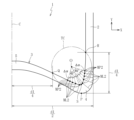
- FIG. 2 is an enlarged longitudinal sectional view showing a main part of the glass tube for pharmaceutical containers shown in FIG. 1.
- FIG. 2 is an enlarged longitudinal sectional view showing a main portion of the pharmaceutical container glass tube of FIG. 1, illustrating a method for calculating the average thickness t1 of the side wall portion.
- FIG. 2 is an enlarged longitudinal sectional view showing a main portion of the pharmaceutical container glass tube of FIG. 1 , illustrating a method for calculating an average thickness t2 of the ground contact portion.
- FIG. 2 is an enlarged longitudinal sectional view showing a main portion of the glass tube for pharmaceutical containers in FIG.
- FIG. 1 is an enlarged longitudinal sectional view showing a main portion of a glass tube for pharmaceutical containers according to Example 1.
- FIG. 4 is an enlarged longitudinal sectional view showing a main part of a glass tube for pharmaceutical containers according to Example 2.
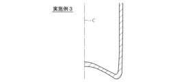
- FIG. 11 is an enlarged longitudinal sectional view showing a main part of a glass tube for pharmaceutical containers according to Example 3.
- FIG. 11 is an enlarged longitudinal sectional view showing a main part of a glass tube for pharmaceutical containers according to Example 4.
- FIG. 1 is an enlarged longitudinal sectional view showing a main portion of a glass tube for pharmaceutical containers according to Example 1.
- FIG. 4 is an enlarged longitudinal sectional view showing a main part of a glass tube for pharmaceutical containers according to Example 2.
- FIG. 11 is an enlarged longitudinal sectional view showing a main part of a glass tube for pharmaceutical containers according to Example 3.
- FIG. 11 is an enlarged longitudinal sectional view showing a main part of a glass tube for pharmaceutical containers according to Example 4.
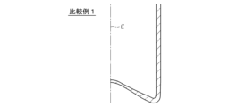
- FIG. 2 is an enlarged longitudinal sectional view showing a main part of a glass tube for pharmaceutical containers according to Comparative Example 1.
- FIG. 4 is an enlarged longitudinal sectional view showing a main portion of a glass tube for pharmaceutical containers according to Comparative Example 2.
- FIG. 11 is an enlarged longitudinal sectional view showing a main part of a glass tube for pharmaceutical containers according to Comparative Example 3.
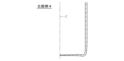
- FIG. 11 is an enlarged longitudinal sectional view showing a main part of a glass tube for pharmaceutical containers according to Comparative Example 4.
- a glass tube 1 for medical containers includes a cylindrical side wall 2 and a bottom 3 sealing one end of the side wall 2.
- the other end of the side wall 2 is not sealed but is open.
- the total length L1 of the pharmaceutical container glass tube 1 in the tube axis direction Y is preferably 500 to 2500 mm, more preferably 800 to 2000 mm, and even more preferably 1000 to 1800 mm.
- the outer diameter d1 of the side wall portion 2 is preferably 4 to 60 mm, more preferably 6 to 50 mm, and even more preferably 8 to 40 mm.
- the pharmaceutical container glass tube 1 is a long, thin body that is elongated in the tube axis direction Y.
- the bottom 3 includes a grounding portion 4 connected to one end of the side wall portion 2 and a raised bottom portion 5 provided on the inside of the grounding portion 4.
- the grounding portion 4 has a grounding point P that touches the flat plate when the pharmaceutical container glass tube 1 is placed on the flat plate in a vertical position.
- the grounding portion 4 corresponds to a corner of the bottom portion 3, and is a ring-shaped area in a plan view (when viewed along the tube axis direction Y).
- the glass tube 1 for pharmaceutical containers satisfies the following relationship. t2/t1>1.025 (1)
- the average thickness t1 of the side wall 2 is the average value (average value of 40 measured values in total) of the thicknesses measured at 10 points for each of the four types of side wall 2 included in any two cross sections passing through the tube axis center line C of the tubular glass 1 for pharmaceutical containers.
- the thickness of the glass as viewed in the normal direction from each measurement point M1 on the inner surface 1a of the tubular glass 1 for pharmaceutical containers (the length of the measurement line ML1 extending from measurement point MP1 in the normal direction of the inner surface 1a and intersecting with the outer surface 1b) is measured.
- the measurement point MP1 for calculating t1 is set as follows.
- any 10 points on the inner surface of the side wall 2 that are at least 1/2 the distance of the outer diameter d1 away from the ground point P in the tube axis direction Y are set as measurement points MP1.
- the measurement points MP1 include positions on the inner surface of the side wall 2 that are d1/2 away from the ground point P in the tube axis direction Y.
- the average thickness t2 of the grounding portion 4 is the average value (average value of 40 measured values in total) of the thicknesses measured at 10 locations for each of the four types of grounding portion 4 included in the two cross sections passing through the tube axis center line C of the tubular glass 1 for pharmaceutical containers that were used to measure the average thickness t1 of the side wall portion 2.
- the thickness of the glass as viewed in the normal direction from each measurement point MP2 on the inner surface 1a of the tubular glass 1 for pharmaceutical containers (the length of the measurement line ML2 that extends from each measurement point MP1 in the normal direction of the inner surface 1a and intersects with the outer surface 1b) is measured.
- the measurement point MP2 for calculating t2 for each of the four types of grounding portion 4 is set as follows. That is, a circle TC is set that passes through a point Q that is a quarter of the outer diameter d1 of the side wall 2 in the radial direction X from the tube axis center line C, a point R that is a quarter of the outer diameter d1 in the tube axis direction Y from a plane extending in the radial direction X that passes through the grounding point P of the grounding part 4, and a point S on the inner surface of the grounding part 4.
- the center point of the circle TC is O
- the point S is the point where the length of the line segment OS is maximum.
- 10 points on the inner surface of the grounding part 4 that exist within a range of 45° to the left and right of the line segment OS based on the center point O are set as measurement points MP2.
- measurement points MP2 are set at every certain angle (central angle) within a range of 45° to the left and right of the line segment OS based on the center point O
- measurement point MP2 includes a position 45° to the left and a position 45° to the right of line segment OS on the inner surface of ground contact portion 4, but does not include point S.
- the glass tube 1 for pharmaceutical containers satisfies the following relationship. (t2-t1)/t1 ⁇ 0.04 (2)
- the lower limit of (t2-t1)/t1 is preferably 0.1 or more from the viewpoint of preventing the pharmaceutical container glass tube 1 from being broken by dropping.
- the upper limit of (t2-t1)/t1 is preferably 0.5 or less, and more preferably 0.3 or less, from the viewpoint of facilitating the forming of the bottom by thermal processing.
- the glass tube 1 for pharmaceutical containers satisfies the relationship of the following formula: 0.4 ⁇ t2/t3 ⁇ 2.3 (3)
- the average thickness t3 at the center of the raised bottom 5 is the average value (average value of 20 measured values in total) of the thicknesses measured at 10 points for each of the two types of raised bottom 5 in the center of any two cross sections passing through the tube axis center line C of the pharmaceutical container tubular glass 1.
- the thickness of the glass as viewed in the normal direction from each measurement point MP3 on the inner surface 1a of the pharmaceutical container tubular glass 1 (the length of the measurement line ML3 extending from each measurement point MP3 in the normal direction of the inner surface 1a and intersecting with the outer surface 1b) is measured.
- the measurement points MP3 for calculating t3 are set as follows.
- five measurement points MP3 are set on the left and right of the tube axis center line C on the inner surface of the raised bottom 5.
- the distance between the leftmost measurement point and the rightmost measurement point is at least 1/4 of d1.
- a total of five measurement points MP3 are set along the radial direction X to the right of the tube axis center line C
- a total of five measurement points MP3 are set along the radial direction X to the left of the tube axis center line C.
- the measurement points MP3 do not include positions on the tube axis center line C on the inner surface of the raised bottom 5.
- the upper limit of t2/t3 is preferably 2.0 or less, and more preferably 1.5 or less, and the lower limit of t2/t3 is preferably 0.7 or more, and more preferably 0.8 or more.
- the glass tube 1 for pharmaceutical containers satisfies the relationship of the following formula: -0.8 ⁇ t2-t3 ⁇ 0.5 (4)
- the upper limit range of t2-t3 is preferably 0.35 mm or less, more preferably 0.3 mm or less, and particularly preferably 0.2 mm or less, and the lower limit range of t2-t3 is preferably -0.6 mm or more, more preferably 0 mm or more, and even more preferably 0.03 mm or more.
- the glass tube 1 for pharmaceutical containers satisfies the relationship of the following formula: -0.8 ⁇ (t2-t3)/t2 ⁇ 0.6 (5)
- the upper limit of (t2-t3)/t2 is preferably 0.35 or less, more preferably 0.3 or less, and particularly preferably 0.2 or less, and the lower limit of (t2-t3)/t2 is preferably -0.6 or more, more preferably 0 or more, and even more preferably 0.03 or more.
- the glass tube 1 for pharmaceutical containers satisfies the following relationship. 0.4 ⁇ t2/t3min ⁇ 2.6 (6)
- the minimum thickness t3min of the raised bottom 5 is the measured thickness of the thinnest part of the raised bottom 5 included in the two cross sections passing through the tube axis center line C of the tubular glass 1 for medical containers, which were used to measure the average thickness t1 of the side wall portion 2.
- the thickness of the glass as viewed in the normal direction from a certain point on the inner surface 1a of the tubular glass 1 for medical containers is measured.
- the part of the raised bottom 5 with the minimum thickness t3min may be formed in the center of the raised bottom 5, or may be formed between the center and the periphery of the raised bottom 5 (the connection between the raised bottom 5 and the ground portion 4).
- the upper limit of t2/t3min is preferably 2.2 or less, more preferably 1.8 or less, and particularly preferably 1.5 or less.
- the lower limit of t2/t3min is preferably 0.6 or more, more preferably 0.8 or more, and even more preferably 1.0 or more.
- the glass tube 1 for pharmaceutical containers satisfies the relationship of the following formula: 0.1 ⁇ (t2) 3 /(ro ⁇ (t1) 2 ) ⁇ 8 (7)
- the relationship of formula (7) is satisfied, even if the glass tube 1 for medical containers is dropped vertically with the bottom 3 facing down onto a flat plate, the maximum tensile stress Tmax generated on the outer surface 1b of the glass tube 1 for medical containers due to the impact of the drop will be small. As a result, the glass tube 1 for medical containers is less likely to break when dropped. In addition, it is possible to easily form the bottom 3 by thermal processing. Furthermore, even if multiple glass tubes 1 for medical containers are bundled together, the outer surfaces of the tube ends can be prevented from coming into contact with each other, making it difficult for the tube ends to be scratched.
- the upper limit range of (t2) 3 /(ro ⁇ (t1) 2 ) is more preferably 3 or less, even more preferably 1.03 or less, and especially preferably 0.9 or less, from the viewpoints of facilitating shaping of the bottom 3 of the medical container glass tube 1 by thermal processing while preventing scratches on the outer surface of the tube end even in a bundled state
- the upper limit range of (t2) 3 /(ro ⁇ (t1) 2 ) is more preferably 3 or less, even more preferably 1.0 or less, and especially preferably 0.9 or less, from the viewpoints of facilitating shaping of the bottom 3 of the medical container glass tube 1 by thermal processing while preventing scratches on the outer surface of the tube end even in a bundled state.
- the lower limit of (t2) 3 /(ro ⁇ (t1) 2 ) is more preferably 0.3 or more, even more preferably 0.65 or more, and particularly preferably 0.7 or more, from the viewpoint of preventing the pharmaceutical container glass tubular 1 from breaking when dropped, when the average thickness t1 of the side wall portion 2 is less than 0.9 mm.
- the lower limit of (t2) 3 /(ro ⁇ (t1) 2 ) is more preferably 0.2 or more, even more preferably 0.25 or more, and particularly preferably 0.3 or more, from the viewpoint of preventing the pharmaceutical container glass tubular 1 from breaking when dropped.
- the glass tube 1 for pharmaceutical containers satisfies the relationship of the following formula. 0.1 ⁇ (t2) 3 /(t1 ⁇ ro) ⁇ 2.5 (8)
- the relationship of formula (8) is satisfied, even if the pharmaceutical container glass tube 1 is dropped vertically with the bottom 3 facing down onto a flat plate, the maximum tensile stress Tmax generated on the outer surface 1b of the pharmaceutical container glass tube 1 due to the impact of the drop will be small. As a result, the pharmaceutical container glass tube 1 is less likely to break when dropped. In addition, the shape of the bottom 3 can be easily formed by thermal processing. Furthermore, even if multiple pharmaceutical container glass tubes are bundled together, the outer surfaces of the tube ends can be prevented from coming into contact with each other, making the tube ends less likely to be scratched.
- the upper limit range of (t2) 3 /(t1 ⁇ ro) is more preferably 1.0 mm or less, even more preferably 0.9 mm or less, and particularly preferably 0.8 mm or less, from the viewpoint of facilitating the shaping by thermal processing of the bottom 3 of the medical container glass tube 1 while preventing scratches on the outer surface of the tube end even in a bundled state.
- the upper limit range of (t2) 3 /(t1 ⁇ ro) is more preferably 0.9 mm or less, even more preferably 0.8 mm or less, and particularly preferably 0.7 mm or less, from the viewpoint of facilitating the shaping by thermal processing of the bottom 3 of the medical container glass tube 1 while preventing scratches on the outer surface of the tube end even in a bundled state.
- the lower limit of (t2) 3 /(t1 ⁇ ro) is preferably 0.2 mm or more, more preferably 0.5 mm or more, and even more preferably 0.7 mm or more, from the viewpoint of preventing the drop breakage of the pharmaceutical container glass tubular 1 when the side wall 2 has an average thickness t1 of less than 0.9 mm
- the lower limit of (t2) 3 /(t1 ⁇ ro) is preferably 0.2 mm or more, more preferably 0.25 mm or more, and even more preferably 0.3 mm or more, from the viewpoint of preventing the drop breakage of the pharmaceutical container glass tubular 1 when the side wall 2 has an average thickness t1 of less than 0.9 mm.
- the glass tube 1 for pharmaceutical containers satisfies the relationship of the following formula. d2/d1 ⁇ 0.86 (9)
- the upper limit of d2/d1 is preferably 0.85 or less, and the lower limit of d2/d1 is preferably 0.4 or more, and more preferably 0.5 or more.
- the glass tube 1 for pharmaceutical containers satisfies the relationship of the following formula. t2 ⁇ t3 ⁇ ro/(t1) 3 >0.3 (10)
- the lower limit of t2 ⁇ t3 ⁇ ro/(t1) 3 is more preferably 0.8 or more, even more preferably 1.5 or more, and especially preferably 2 or more, from the viewpoint of preventing the pharmaceutical container glass tube 1 from being broken when dropped, when the average thickness t1 of the sidewall 2 is less than 0.9 mm.
- the lower limit of t2 ⁇ t3 ⁇ ro/(t1) 3 is more preferably 0.7 or more, even more preferably 2 or more, and especially preferably 3 or more, from the viewpoint of preventing the pharmaceutical container glass tube 1 from being broken when dropped.
- the upper limit of t2 ⁇ t3 ⁇ ro/(t1) 3 is preferably 5 or less, more preferably 4 or less, and even more preferably 3 or less, from the viewpoint of facilitating molding by thermal processing.
- the upper limit range of t2 ⁇ t3 ⁇ ro/(t1) 3 is preferably 5 or less, more preferably 4 or less, and even more preferably 3.8 or less, from the viewpoint of facilitating molding by thermal processing.
- the angle ⁇ of the inner surface of the grounding portion 4 is preferably 50 to 90°, more preferably 55 to 80°, and even more preferably 60 to 70°. If the angle ⁇ of the inner surface of the grounding portion 4 is too small, it becomes difficult to form the bottom 3 by thermal processing. On the other hand, if the angle ⁇ of the inner surface of the grounding portion 4 is too large, the bottom 3 is more likely to receive impact when dropped, and it may be difficult to suppress damage.
- the angle ⁇ is the angle between the tangent LQ of the inner surface of the bottom 3 at point Q, which is a distance of 1/4 of the outer diameter d1 of the side wall 2 outward in the radial direction X from the tube axis center line C, and the tangent LR of the inner surface of the side wall 2 at point R, which is a distance of 1/4 of d1 upward in the tube axis direction Y from a plane extending in the radial direction X that passes through the grounding point P of the grounding portion 4.
- the average thickness t2 of the grounding portion 4 is preferably 0.6 to 1.4 mm, more preferably 0.8 to 1.3 mm or less, and particularly preferably 0.9 to 1.2 mm.
- the average thickness t2 of the grounding portion 4 is preferably 0.3 to 1.1 mm, more preferably 0.4 to 1.0 mm or less, and particularly preferably 0.50 to 0.95 mm.
- the average thickness t3 at the center of the raised bottom 5 is preferably 0.6 to 1.4 mm, more preferably 0.8 to 1.3 mm or less, and particularly preferably 0.9 to 1.2 mm.
- the average thickness t3 at the center of the raised bottom 5 is preferably 0.3 to 1.1 mm, more preferably 0.4 to 1.0 mm or less, and particularly preferably 0.50 to 0.95 mm.
- the maximum tensile stress Tmax generated on the outer surface 1b is 55 MPa or less.
- the maximum tensile stress Tmax is a value obtained by simulation.
- the length L1 of the pharmaceutical container glass tube 1 is 1500 mm
- the flat plate onto which it is dropped is a Teflon (registered trademark) plate.
- the simulation can be performed, for example, by time history response analysis using the finite element method.
- FEM software for example, Abaqus made by Dassault Systèmes, ANSYS Mechanical made by ANSYS, or Marc made by MSC can be used.
- the maximum tensile stress Tmax generated on the outer surface 1b of the pharmaceutical container glass tube 1 due to the impact of being dropped is preferably 50 MPa or less, more preferably 45 MPa or less, and most preferably 43 MPa or less.
- the manufacturing method of the glass tube 1 for medical containers having the above-mentioned configuration includes a preparation step of preparing a long original glass tube formed by the Danner method or the like, a sealing step of heating and sealing one end opening of the original glass tube with a burner, and a thermal processing step of thermally processing the sealed part into a shape corresponding to the bottom part 3 of the glass tube 1 for medical containers.
- the sealed part of the original glass tube may be heated with a burner while the sealed one end opening is facing upward. In this way, the center of the softened sealed part is bent downward by gravity, and the bottom part 3 having the ground part 4 and the raised bottom part 5 is formed.
- the bottom part 3 having the ground part 4 and the raised bottom part 5 may be formed by applying pressure from the outside to the inside of the tube to the sealed one end opening with a pressing member during or immediately after heating with the burner.
- the heating time using a burner in the thermal processing step is preferably 1 to 60 seconds, and more preferably 3 to 45 seconds.
- the pharmaceutical container glass tubular material 1 having the above-described configuration is processed to manufacture pharmaceutical containers.
- the pharmaceutical containers include ampoules, syringes, and vials.
- the method for manufacturing pharmaceutical containers includes a preparation step of setting the pharmaceutical container glass tube 1 in a vertical position with the bottom 3 facing down, a cutting step of heating a part of the pharmaceutical container glass tube 1 in the vertical position with a burner and cutting it to a predetermined length to obtain a container intermediate, and a thermal processing step of heating the end of the container intermediate with a burner to form it into a predetermined shape to obtain a pharmaceutical container.
- a preparation step of setting the pharmaceutical container glass tube 1 in a vertical position with the bottom 3 facing down a cutting step of heating a part of the pharmaceutical container glass tube 1 in the vertical position with a burner and cutting it to a predetermined length to obtain a container intermediate
- a thermal processing step of heating the end of the container intermediate with a burner to form it into a predetermined shape to obtain a pharmaceutical container.
- the vertically oriented glass tube 1 for pharmaceutical containers may be dropped onto a flat plate 6 with its bottom 3 facing down, thereby setting the vertically oriented glass tube 1 for pharmaceutical containers in a predetermined position.
- the shape of the bottom 3 of the glass tube 1 for pharmaceutical containers is regulated as described above, the glass tube 1 for pharmaceutical containers is less likely to break even if it is subjected to a drop impact due to collision with the flat plate 6. This improves the productivity of pharmaceutical containers.
- the bottom 3 of the glass tube 1 for pharmaceutical containers is removed, so that the bottom 3 of the glass tube 1 for pharmaceutical containers does not remain in the manufactured pharmaceutical containers.
- one end of the side wall 2 of the pharmaceutical container glass tube 1 is sealed with the bottom 3, and the other end of the side wall 2 is open and not sealed.
- the present invention is not limited to this. Both ends of the side wall 2 of the pharmaceutical container glass tube 1 may be sealed. In this way, it is possible to prevent foreign matter from entering the pharmaceutical container glass tube before the pharmaceutical container is manufactured using the pharmaceutical container glass tube 1. Therefore, a pharmaceutical container with high cleanliness can be manufactured.
- the bottom 3 having the above-mentioned shape may be formed on both ends of the side wall 2, or the bottom 3 having the above-mentioned shape may be formed on only one end of the side wall 2.
- glass tubes for pharmaceutical containers as shown in Figures 7 to 10 were produced, and as Comparative Examples 1 to 4, glass tubes for pharmaceutical containers as shown in Figures 11 to 14 were produced.
- the glass tubes for pharmaceutical containers shown in Examples 1 to 4 were produced by extending and adjusting the heating time with a burner in the range of 1.1 to 2 times longer than the glass tubes for pharmaceutical containers in Comparative Examples 1 to 4. Shape data was measured for each of these glass tubes for pharmaceutical containers. The results are shown in Table 1.
- t1 is the average thickness of the side wall
- t2 is the average thickness of the ground contact portion
- t3 is the average thickness at the center of the raised bottom
- t3min is the minimum thickness of the raised bottom
- ro is the radial distance from the ground contact point of the ground contact portion to the outer circumferential surface of the side wall
- d1 is the outer diameter of the side wall
- d2 is the diameter of the circle formed by the ground contact point of the ground contact portion
- ⁇ is the angle of the inner surface of the ground contact portion
- Tmax is the maximum tensile stress (simulation) generated on the outer surface of the tubular glass for pharmaceutical containers due to the impact of being dropped.
- Reference Signs List 1 Tube glass for medical containers 2: Side wall 3: Bottom 4: Grounding portion 5: Raised bottom P: Grounding point C: Tube axis center line X: Radial direction Y: Tube axis direction t1: Average thickness of side wall t2: Average thickness of grounding portion t3: Average thickness at the center of raised bottom ⁇ : Angle of inner surface of grounding portion
Landscapes
- Health & Medical Sciences (AREA)
- Hematology (AREA)
- Pharmacology & Pharmacy (AREA)
- Life Sciences & Earth Sciences (AREA)
- Animal Behavior & Ethology (AREA)
- General Health & Medical Sciences (AREA)
- Public Health (AREA)
- Veterinary Medicine (AREA)
- Chemical & Material Sciences (AREA)
- Engineering & Computer Science (AREA)
- Materials Engineering (AREA)
- Organic Chemistry (AREA)
- Medical Preparation Storing Or Oral Administration Devices (AREA)
- Re-Forming, After-Treatment, Cutting And Transporting Of Glass Products (AREA)
Abstract
医薬容器用管ガラス1は、円筒状の側壁部2と、側壁部2の一端部側を封止する底部3と、を備える。底部3は、側壁部2の一端部に連結された接地部4と、接地部4の内側に設けられた上げ底部5と、を備える。側壁部2の平均厚みt1[mm]と、接地部4の平均厚みt2[mm]とが、t2/t1>1.025なる関係を満たす。
Description
本発明は、医薬容器用管ガラス及び医薬容器の製造方法に関する。
医薬容器の製造工程では、まず、医薬容器の製造装置に対して、長尺な医薬容器用管ガラスを縦姿勢(例えば、管軸方向が垂直方向を向く姿勢)でセットする。その後、この縦姿勢の医薬容器用管ガラスをバーナーで加熱して切断したり、所定形状に熱加工したりする。これにより、一本の医薬容器用管ガラスから複数の医薬容器が順次製造される(例えば、特許文献1、2を参照)。
医薬容器の製造工程において、医薬容器の製造装置に対して医薬容器用管ガラスを縦姿勢でセットするために、底部を下にした縦姿勢の医薬容器用管ガラスを平板上に落下させる場合がある。
しかしながら、医薬容器用管ガラスの底部の形状が不適当であると、医薬容器用管ガラスが落下衝撃により破損する場合がある。
本発明は、医薬容器用管ガラスが落下衝撃によって破損するのを抑制することを課題とする。
(1) 上記の課題を解決するために創案された本発明は、円筒状の側壁部と、側壁部の一端部側を封止する底部と、を備える医薬容器用管ガラスであって、底部は、側壁部の一端部に連結された接地部と、接地部の内側に設けられた上げ底部と、を備え、側壁部の平均厚みt1[mm]と、接地部の平均厚みt2[mm]とが、t2/t1>1.025なる関係を満たすことを特徴とする。
このようにすれば、底部を下にした縦姿勢の医薬容器用管ガラスを平板上に落下させても、落下衝撃に伴って医薬容器用管ガラスの外表面に生じる最大引張応力は小さくなる。その結果、医薬容器用管ガラスが落下衝撃によって破損しにくくなる。
(2) 上記(1)の構成において、接地部の平均厚みt2[mm]と、上げ底部の中心部における平均厚みt3[mm]とが、-0.8<(t2-t3)<0.5なる関係を満たすことが好ましい。
このようにすれば、底部を下にした縦姿勢の医薬容器用管ガラスを平板上に落下させても、落下衝撃に伴って医薬容器用管ガラスの外表面に生じる最大引張応力は小さくなり、医薬容器用管ガラスの落下破損がより生じにくくなる。
(3) 上記(1)又は(2)の構成において、接地部の平均厚みt2[mm]と、上げ底部の中心部における平均厚みt3[mm]とが、-0.8<(t2-t3)/t2<0.6なる関係を満たすことが好ましい。
このようにすれば、底部を下にした縦姿勢の医薬容器用管ガラスを平板上に落下させても、落下衝撃に伴って医薬容器用管ガラスの外表面に生じる最大引張応力は小さくなり、医薬容器用管ガラスの落下破損がより生じにくくなる。
(4) 上記(1)~(3)の構成のいずれかにおいて、接地部の平均厚みt2[mm]と、上げ底部の最小厚みt3min[mm]とが、0.4<t2/t3min<2.6なる関係を満たすことが好ましい。
このようにすれば、底部を下にした縦姿勢の医薬容器用管ガラスを平板上に落下させても、落下衝撃に伴って医薬容器用管ガラスの外表面に生じる最大引張応力は小さくなる。その結果、医薬容器用管ガラスの落下破損がより生じにくくなる。
(5) 上記(1)~(4)のいずれかの構成において、接地部の平均厚みt2[mm]と、接地部の接地点から側壁部の外周面の仮想延長面までの径方向距離ro[mm]とが、0.1≦(t2)3/(ro×(t1)2)≦8なる関係を満たすことが好ましい。
このようにすれば、落下衝撃に対する医薬容器用管ガラスの破損強度を高めつつ、熱加工により底部の形状を成形しやすくなる。また、複数本の医薬容器用管ガラスを束状態にしても、互いの管端部の外表面の接触を防止できる。換言すれば、(t2)3/(ro×(t1)2)の値が大きくなりすぎると、底部の熱加工による成形が困難になるおそれがあり、その結果、生産性が低下しやすくなる。また、接地部(接地点)が管軸と離れた方向に位置しやすくなり、医薬容器用管ガラスの管端部同士が接触したりするおそれがあるため、管端に傷が生じやすい。一方、(t2)3/(ro×(t1)2)の値が小さくなりすぎると、落下衝撃によって医薬容器用管ガラスが破損しやすくなる。
(6) 上記(1)~(5)のいずれかの構成において、側壁部の平均厚みt1[mm]と、接地部の平均厚みt2[mm]と、接地部の接地点から側壁部の外周面の仮想延長面までの径方向距離ro[mm]とが、0.1≦(t2)3/(t1×ro)≦0.8なる関係を満たすことが好ましい。
このようにすれば、落下衝撃に対する医薬容器用管ガラスの破損強度を高めつつ、熱加工により底部の形状を成形しやすくなる。また、複数本の医薬容器用管ガラスを束状態にしても、互いの管端部の外表面の接触を防止できるため、管端に傷が生じにくい。
(7) 上記(1)~(6)のいずれかの構成において、側壁部の外径d1[mm]と、接地部の接地点により形成される円の直径d2[mm]とが、d2/d1≦0.86なる関係を満たすことが好ましい。
このようにすれば、底部を下にした縦姿勢の医薬容器用管ガラスを平板上に落下させても、落下衝撃に伴って医薬容器用管ガラスの外表面に生じる最大引張応力は小さくなる。その結果、医薬容器用管ガラスの落下破損がより生じにくくなる。
(8) 上記(1)~(7)のいずれかの構成において、接地部の平均厚みt2[mm]と、上げ底部の中心部における平均厚みt3[mm]と、接地部の接地点から側壁部の外周面までの径方向距離ro[mm]とが、t2×t3×ro/(t1)3>0.3なる関係を満たすことが好ましい。
このようにすれば、底部を下にした縦姿勢の医薬容器用管ガラスを平板上に落下させても、落下衝撃に伴って医薬容器用管ガラスの外表面に生じる最大引張応力は小さくなる。その結果、医薬容器用管ガラスの落下破損がより生じにくくなる。
(9) 上記(1)~(8)のいずれかの構成において、底部を下にした縦姿勢の医薬容器用管ガラスを450mmの高さからテフロン(登録商標)板上に落下させた場合に、医薬容器用管ガラスの外表面に発生する最大引張応力が55MPa以下であることが好ましい。
このようにすれば、医薬容器用管ガラスの落下破損がより生じにくくなる。
(10) 上記(1)~(9)のいずれかの構成において、医薬容器用管ガラスの管軸方向の全長が、500mm以上であることが好ましい。
このようにすれば、医薬容器用管ガラスが十分に長尺体となる。そのため、一本の医薬容器用管ガラスから多数の医薬容器を製造することができ、医薬容器の生産性が向上する。
(11) 上記(1)~(10)のいずれかの構成において、側壁部の両端部が封止されていてもよい。
このようにすれば、医薬容器用管ガラスの内部に異物が侵入する事態を防止できる。
(12) 上記の課題を解決するために創案された本発明は、医薬用容器の製造方法であって、上記(1)~(11)のいずれかの構成を備えた医薬容器用管ガラスを加工して、医薬用容器を製造することを特徴する。
このようにすれば、医薬容器用管ガラスの落下破損を抑制できるため、医薬容器の生産性が向上する。
本発明によれば、医薬容器用管ガラスが落下衝撃によって破損するのを抑制できる。
以下、本発明の実施形態を添付図面に基づいて説明する。
(医薬容器用管ガラス)
図1に示すように、本実施形態に係る医薬容器用管ガラス1は、円筒状の側壁部2と、側壁部2の一端部側を封止する底部3と、を備える。なお、本実施形態では、側壁部2の他端部側は封止されずに開口している。
図1に示すように、本実施形態に係る医薬容器用管ガラス1は、円筒状の側壁部2と、側壁部2の一端部側を封止する底部3と、を備える。なお、本実施形態では、側壁部2の他端部側は封止されずに開口している。
医薬容器用管ガラス1の管軸方向Yの全長L1は、500~2500mmであることが好ましく、800~2000mmであることがより好ましく、1000~1800mmであることがさらに好ましい。側壁部2の外径d1は、4~60mmであることが好ましく、6~50mmであることがより好ましく、8~40mmであることがさらに好ましい。つまり、医薬容器用管ガラス1は、管軸方向Yに細長い長尺体である。
底部3は、側壁部2の一端部に連結された接地部4と、接地部4の内側に設けられた上げ底部5と、を備える。
接地部4は、医薬容器用管ガラス1を縦姿勢で平板上に載置した場合に、平板に接地する接地点Pを有する。接地部4は、底部3の角部に相当し、平面視(管軸方向Yに沿ってみた場合)で円環状の領域である。
上げ底部5は、医薬容器用管ガラス1を縦姿勢で平板上に載置した場合に、平板に接地せずに上方に退避する部分である。上げ底部5は、平面視で円形状の領域である。上げ底部5は、例えば、半径方向Xに沿って延びる平面部で形成されていてもよいし、中心部が最も高位に位置する凸曲面で形成されていてもよい。本実施形態では、上げ底部5の周縁部が接地部4に接続されている。
図2に示すように、側壁部2の平均厚みをt1[mm]、接地部4の平均厚みをt2[mm]とすると、医薬容器用管ガラス1は、下式の関係を満たす。
t2/t1>1.025 (1)
t2/t1>1.025 (1)
ここで、側壁部2の平均厚みt1は、医薬容器用管ガラス1の管軸中心線Cを通る任意の2つの断面に含まれる4種の側壁部2について、それぞれ10か所ずつ厚みを測定した平均値(計40か所の測定値の平均値)とする。この際、図3に示すように、医薬容器用管ガラス1の内表面1aの各測点M1から法線方向にみたガラスの厚み(測点MP1から内表面1aの法線方向に延び外表面1bと交わる測線ML1の長さ)を測定するものとする。詳細には、4種の側壁部2のそれぞれについて、t1を算出するための測点MP1は以下のように設定する。すなわち、接地点Pから管軸方向Yに外径d1の1/2の距離以上離れた側壁部2の内表面上の任意の10点を測点MP1とする。例えば、側壁部2の内表面上において、接地点Pから管軸方向Yにd1/2離れた位置から管軸方向Yに沿って距離ΔY(ΔY=0.5mm)毎に計10点の測点MP1を設ける。なお、この例では、測点MP1は、側壁部2の内表面における、接地点Pから管軸方向Yにd1/2離れた位置を含む。
接地部4の平均厚みt2は、側壁部2の平均厚みt1の測定に用いた、医薬容器用管ガラス1の管軸中心線Cを通る2つの断面に含まれる4種の接地部4について、それぞれ10か所ずつ厚みを測定した平均値(計40か所の測定値の平均値)とする。この際、図4に示すように、医薬容器用管ガラス1の内表面1aの各測点MP2から法線方向にみたガラスの厚み(各測点MP1から内表面1aの法線方向に延び外表面1bと交わる測線ML2の長さ)を測定するものとする。詳細には、4種の接地部4のそれぞれについて、t2を算出するための測点MP2は以下のように設定する。すなわち、管軸中心線Cから半径方向Xの外側に側壁部2の外径d1の1/4の距離だけ離れた点Qと、接地部4の接地点Pを通る半径方向Xに延びる平面から管軸方向Yの上方に外径d1の1/4の距離だけ離れた点Rと、接地部4の内表面上にある点Sとを通る円TCを設定する。この際、円TCの中心点をOとすると、点Sは線分OSの長さが最大となる点である。そして、中心点Oを基準とする線分OSの左右45°の範囲に存在する接地部4の内表面上の10点を測点MP2とする。例えば、中心点Oを基準とする線分OSの左右45°の範囲に一定の角度(中心角)毎に測点MP2を設定する場合は、接地部4の内表面上において、中心点Oを基準とする線分OSの左45°の位置(又は右45°の位置)から角度Δα(Δα=10°)毎に計10点の測点MP2を設ける。なお、この例では、測点MP2は、接地部4の内表面における、線分OSの左45°の位置及び右45°の位置を含むが、点Sを含まない。
式(1)の関係を満たせば、底部3を下にした縦姿勢の医薬容器用管ガラス1を平板上に落下させても、落下衝撃によって医薬容器用管ガラス1の外表面1bに生じる最大引張応力Tmaxが小さくなる。その結果、医薬容器用管ガラス1が落下衝撃によって破損しにくくなる。
t2/t1の下限範囲は、医薬容器用管ガラス1の落下破損を抑制する観点からは、1.05以上であることがより好ましく、1.10以上であることがさらに好ましく、1.12以上であることが特に好ましい。一方、t2/t1の上限範囲は、底部3の熱加工による成形を容易にする観点からは、1.4以下であることが好ましく、1.35以下であることがより好ましく、1.30以下であることがさらに好ましい。
図2に示すように、側壁部2の平均厚みをt1[mm]、接地部4の平均厚みをt2[mm]とすると、医薬容器用管ガラス1は、下式の関係を満たすことが好ましい。
(t2-t1)/t1≧0.04 (2)
(t2-t1)/t1≧0.04 (2)
式(2)の関係を満たせば、底部3を下にした縦姿勢の医薬容器用管ガラス1を平板上に落下させても、落下衝撃によって医薬容器用管ガラス1の外表面1bに生じる最大引張応力Tmaxが小さくなる。その結果、医薬容器用管ガラス1の落下破損がより生じにくくなる。
(t2-t1)/t1の下限範囲は、医薬容器用管ガラス1の落下破損を抑制する観点からは、0.1以上であることがより好ましい。一方、(t2-t1)/t1の上限範囲は、底部の熱加工による成形を容易にする観点からは、0.5以下であることが好ましく、0.3以下であることがより好ましい。
図2に示すように、接地部4の平均厚みをt2[mm]、上げ底部5の中心部(管軸中心線C付近)における平均厚みをt3[mm]とすると、医薬容器用管ガラス1は、下式の関係を満たすことが好ましい。
0.4<t2/t3<2.3 (3)
0.4<t2/t3<2.3 (3)
ここで、上げ底部5の中心部における平均厚みt3は、医薬容器用管ガラス1の管軸中心線Cを通る任意の2つの断面に含まれる2種の上げ底部5の中心部について、それぞれ10か所ずつ厚みを測定した平均値(計20か所の測定値の平均値)とする。この際、図5に示すように、医薬容器用管ガラス1の内表面1aの各測点MP3から法線方向にみたガラスの厚み(各測点MP3から内表面1aの法線方向に延び外表面1bと交わる測線ML3の長さ)を測定するものとする。詳細には、2種の上げ底部5のそれぞれについて、t3を算出するための測点MP3は、以下のように設定する。すなわち、上げ底部5の内表面上に管軸中心線Cから左右に5点ずつ測点MP3を設定する。ただし、上記10点の測点MP3のち、最左端の測点と最右端の測点との距離は、d1の1/4以上の距離である。詳細には、例えば、上げ底部5の中心部の内表面において、管軸中心線Cから右側に半径方向Xに沿って計5点の測点MP3を設定すると共に、管軸中心線Cから左側に半径方向Xに沿って計5点の測点MP3を設定する。なお、この例では、測点MP3は、上げ底部5の内表面における、管軸中心線C上の位置は含まない。
式(3)の関係を満たせば、底部3を下にした縦姿勢の医薬容器用管ガラス1を平板上に落下させても、落下衝撃によって医薬容器用管ガラス1の外表面1bに生じる最大引張応力Tmaxが小さくなる。その結果、医薬容器用管ガラス1の落下破損がより生じにくくなる。
医薬容器用管ガラス1の落下破損を抑制する観点からは、t2/t3の上限範囲は、2.0以下であることがより好ましく、1.5以下であることがさらに好ましく、t2/t3の下限範囲は、0.7以上であることが好ましく、0.8以上であることがより好ましい。
図2に示すように、接地部4の平均厚みをt2[mm]、上げ底部5の中心部(管軸中心線C付近)における平均厚みをt3[mm]とすると、医薬容器用管ガラス1は、下式の関係を満たすことが好ましい。
-0.8<t2-t3<0.5 (4)
-0.8<t2-t3<0.5 (4)
式(4)の関係を満たせば、底部3を下にした縦姿勢の医薬容器用管ガラス1を平板上に落下させても、落下衝撃によって医薬容器用管ガラス1の外表面1bに生じる最大引張応力Tmaxが小さくなる。その結果、医薬容器用管ガラス1の落下破損がより生じにくくなる。
医薬容器用管ガラス1の落下破損を抑制する観点からは、t2-t3の上限範囲は、0.35mm以下であることがより好ましく、0.3mm以下であることがさらに好ましく、0.2mm以下であることが特に好ましく、t2-t3の下限範囲は、-0.6mm以上であることが好ましく、0mm以上であることがより好ましく、0.03mm以上であることがさらに好ましい。
図2に示すように、接地部4の平均厚みをt2[mm]、上げ底部5の中心部(管軸中心線C付近)における平均厚みをt3[mm]とすると、医薬容器用管ガラス1は、下式の関係を満たすことが好ましい。
-0.8<(t2-t3)/t2<0.6 (5)
-0.8<(t2-t3)/t2<0.6 (5)
式(5)の関係を満たせば、底部3を下にした縦姿勢の医薬容器用管ガラス1を平板上に落下させても、落下衝撃によって医薬容器用管ガラス1の外表面1bに生じる最大引張応力Tmaxが小さくなる。その結果、医薬容器用管ガラス1の落下破損がより生じにくくなる。
医薬容器用管ガラス1の落下破損を抑制する観点からは、(t2-t3)/t2の上限範囲は、0.35以下であることがより好ましく、0.3以下であることがさらに好ましく、0.2以下であることが特に好ましく、(t2-t3)/t2の下限範囲は、-0.6以上であることが好ましく、0以上であることがより好ましく、0.03以上であることがさらに好ましい。
図2に示すように、接地部4の平均厚みをt2[mm]、上げ底部5の最小厚みt3min[mm]とすると、医薬容器用管ガラス1は、下式の関係を満たすことが好ましい。
0.4<t2/t3min<2.6 (6)
0.4<t2/t3min<2.6 (6)
ここで、上げ底部5の最小厚みt3minは、側壁部2の平均厚みt1の測定に用いた、医薬容器用管ガラス1の管軸中心線Cを通る2つの断面に含まれる上げ底部5の中で、最も薄い部分の厚みを測定した値とする。この際、医薬容器用管ガラス1の内表面1aのある点から法線方向にみたガラスの厚みを測定するものとする。上げ底部5のうち最小厚みt3minとなる部分は、上げ底部5の中心部に形成されていてもよいし、上げ底部5の中心部と周縁部(上げ底部5と接地部4との連結部)との間に形成されていてもよい。
式(6)の関係を満たせば、底部3を下にした縦姿勢の医薬容器用管ガラス1を平板上に落下させても、落下衝撃によって医薬容器用管ガラス1の外表面1bに生じる最大引張応力Tmaxが小さくなる。その結果、医薬容器用管ガラス1の落下破損がより生じにくくなる。
医薬容器用管ガラス1の落下破損を抑制する観点からは、t2/t3minの上限範囲は、2.2以下であることがより好ましく、1.8以下であることがさらに好ましく、1.5以下であることが特に好ましい。一方、t2/t3minの下限範囲は、0.6以上であることが好ましく、0.8以上であることがより好ましく、1.0以上であることがさらに好ましい。
図2に示すように、接地部4の平均厚みをt2[mm]、接地部4の接地点Pから側壁部2の外周面(厳密には、側壁部2の外周面の仮想延長面)までの径方向距離をro[mm]とすると、医薬容器用管ガラス1は、下式の関係を満たすことが好ましい。
0.1≦(t2)3/(ro×(t1)2)≦8 (7)
0.1≦(t2)3/(ro×(t1)2)≦8 (7)
式(7)の関係を満たせば、底部3を下にした縦姿勢の医薬容器用管ガラス1を平板上に落下させても、落下衝撃によって医薬容器用管ガラス1の外表面1bに生じる最大引張応力Tmaxが小さくなる。その結果、医薬容器用管ガラス1の落下破損がより生じにくくなる。また、底部3の熱加工による成形を容易にすることができる。さらに、複数本の医薬容器用管ガラス1を束状態にしても、互いの管端部の外表面の接触を防止できるため、管端に傷が生じにくい。
(t2)3/(ro×(t1)2)の上限範囲は、側壁部2の平均厚みt1が0.9mm以上の場合、医薬容器用管ガラス1の底部3の熱加工による成形を容易にしつつ、束状態にしても管端部の外表面の傷を防止する観点からは、3以下であることがより好ましく、1.03以下であることがさらに好ましく、0.9以下であることが特に好ましい。(t2)3/(ro×(t1)2)の上限範囲は、側壁部2の平均厚みt1が0.9mm未満の場合、医薬容器用管ガラス1の底部3の熱加工による成形を容易にしつつ、束状態にしても管端部の外表面の傷を防止する観点からは、3以下であることがより好ましく、1.0以下であることがさらに好ましく、0.9以下であることが特に好ましい。一方、(t2)3/(ro×(t1)2)の下限範囲は、側壁部2の平均厚みt1が0.9mm以上の場合、医薬容器用管ガラス1の落下破損を抑制する観点からは、0.3以上であることがより好ましく、0.65以上であることがさらに好ましく、0.7以上であることが特に好ましい。(t2)3/(ro×(t1)2)の下限範囲は、側壁部2の平均厚みt1が0.9mm未満の場合、医薬容器用管ガラス1の落下破損を抑制する観点からは、0.2以上であることがより好ましく、0.25以上であることがさらに好ましく、0.3以上であることが特に好ましい。
側壁部2の平均厚みをt1[mm]、接地部4の平均厚みをt2[mm]、接地部4の接地点Pから側壁部2までの径方向距離をro[mm]とすると、医薬容器用管ガラス1は、下式の関係を満たす。
0.1≦(t2)3/(t1×ro)≦2.5 (8)
0.1≦(t2)3/(t1×ro)≦2.5 (8)
式(8)の関係を満たせば、底部3を下にした縦姿勢の医薬容器用管ガラス1を平板上に落下させても、落下衝撃によって医薬容器用管ガラス1の外表面1bに生じる最大引張応力Tmaxが小さくなる。その結果、医薬容器用管ガラス1の落下破損がより生じにくくなる。また、熱加工により底部3の形状を成形しやすくなる。さらに、複数本の医薬容器用管ガラスを束状態にしても、互いの管端部の外表面の接触を防止できるため、管端に傷が生じにくい。
(t2)3/(t1×ro)の上限範囲は、側壁部2の平均厚みt1が0.9mm以上の場合、医薬容器用管ガラス1の底部3の熱加工による成形を容易にしつつ、束状態にしても管端部の外表面の傷を防止する観点からは、1.0mm以下であることがより好ましく、0.9mm以下であることがさらに好ましく、0.8mm以下であることが特に好ましい。(t2)3/(t1×ro)の上限範囲は、側壁部2の平均厚みt1が0.9mm未満の場合、医薬容器用管ガラス1の底部3の熱加工による成形を容易にしつつ、束状態にしても管端部の外表面の傷を防止する観点からは、0.9mm以下であることがより好ましく、0.8mm以下であることがさらに好ましく、0.7mm以下であることが特に好ましい。一方、(t2)3/(t1×ro)の下限範囲は、側壁部2の平均厚みt1が0.9mm以上の場合、医薬容器用管ガラス1の落下破損を抑制する観点からは、0.2mm以上であることが好ましく、0.5mm以上であることがより好ましく、0.7mm以上であることがさらに好ましい。(t2)3/(t1×ro)の下限範囲は、側壁部2の平均厚みt1が0.9mm未満の場合、医薬容器用管ガラス1の落下破損を抑制する観点からは、0.2mm以上であることが好ましく、0.25mm以上であることがより好ましく、0.3mm以上であることがさらに好ましい。
図1及び図2に示すように、側壁部2の外径をd1[mm]、接地部4の接地点Pにより形成される円の直径をd2[mm]とすると、医薬容器用管ガラス1は、下式の関係を満たす。
d2/d1≦0.86 (9)
d2/d1≦0.86 (9)
式(8)の関係を満たせば、底部3を下にした縦姿勢の医薬容器用管ガラス1を平板上に落下させても、落下衝撃によって医薬容器用管ガラス1の外表面1bに生じる最大引張応力Tmaxが小さくなる。その結果、医薬容器用管ガラス1の落下破損がより生じにくくなる。
医薬容器用管ガラス1の落下破損を抑制する観点からは、d2/d1の上限範囲は、0.85以下であることがより好ましく、d2/d1の下限範囲は、0.4以上であることが好ましく、0.5以上であることがより好ましい。
図2に示すように、接地部4の平均厚みをt2[mm]、上げ底部5の中心部における平均厚みをt3[mm]、接地部4の接地点Pから側壁部2の外周面までの径方向距離をro[mm]とすると、医薬容器用管ガラス1は、下式の関係を満たす。
t2×t3×ro/(t1)3>0.3 (10)
t2×t3×ro/(t1)3>0.3 (10)
式(10)の関係を満たせば底部3を下にした縦姿勢の医薬容器用管ガラス1を平板上に落下させても、落下衝撃によって医薬容器用管ガラス1の外表面1bに生じる最大引張応力Tmaxが小さくなる。その結果、医薬容器用管ガラス1の落下破損がより生じにくくなる。
t2×t3×ro/(t1)3の下限範囲は、側壁部2の平均厚みt1が0.9mm以上の場合、医薬容器用管ガラス1の落下破損を抑制する観点からは、0.8以上であることがより好ましく、1.5以上であることがさらに好ましく、2以上であることが特に好ましい。t2×t3×ro/(t1)3の下限範囲は、側壁部2の平均厚みt1が0.9mm未満の場合、医薬容器用管ガラス1の落下破損を抑制する観点からは、0.7以上であることがより好ましく、2以上であることがさらに好ましく、3以上であることが特に好ましい。一方、t2×t3×ro/(t1)3の上限範囲は、側壁部2の平均厚みt1が0.9mm以上の場合、熱加工による成形を容易にする観点からは、5以下であることが好ましく、4以下であることがより好ましく、3以下であることがさらに好ましい。t2×t3×ro/(t1)3の上限範囲は、側壁部2の平均厚みt1が0.9mm未満の場合、熱加工による成形を容易にする観点からは、5以下であることが好ましく、4以下であることがより好ましく、3.8以下であることがさらに好ましい。
図2に示すように、接地部4の内表面の角度θは、50~90°であることが好ましく、55~80°であることがより好ましく、60~70°であることがさらに好ましい。接地部4の内表面の角度θが小さくなりすぎると、底部3を熱加工により形成しにくくなる。一方、接地部4の内表面の角度θが大きくなりすぎると、落下時に底部3において衝撃を受けやすくなるため、破損を抑制しにくくなるおそれがある。ここで、角度θは、管軸中心線Cから半径方向Xの外側に側壁部2の外径d1の1/4の距離だけ離れた点Qにおける底部3の内表面の接線LQと、接地部4の接地点Pを通る半径方向Xに延びる平面から管軸方向Yの上方にd1の1/4の距離だけ離れた点Rにおける側壁部2の内表面の接線LRとのなす角とする。
側壁部2の平均厚みt1が0.9mm以上の場合、医薬容器用管ガラス1の落下破損を抑制する観点からは、接地部4の平均厚みをt2は、0.6~1.4mmであることが好ましく、0.8~1.3mm以下であることがより好ましく、0.9~1.2mmであることが特に好ましい。側壁部2の平均厚みt1が0.9mm未満の場合、医薬容器用管ガラス1の落下破損を抑制する観点からは、接地部4の平均厚みをt2は、0.3~1.1mmであることが好ましく、0.4~1.0mm以下であることがより好ましく、0.50~0.95mmであることが特に好ましい。
側壁部2の平均厚みt1が0.9mm以上の場合、医薬容器用管ガラス1の落下破損を抑制する観点からは、上げ底部5の中心部における平均厚みをt3は、0.6~1.4mmであることが好ましく、0.8~1.3mm以下であることがより好ましく、0.9~1.2mmであることが特に好ましい。側壁部2の平均厚みt1が0.9mm未満の場合、医薬容器用管ガラス1の落下破損を抑制する観点からは、上げ底部5の中心部における平均厚みをt3は、0.3~1.1mmであることが好ましく、0.4~1.0mm以下であることがより好ましく、0.50~0.95mmであることが特に好ましい。
以上の構成を備えた医薬容器用管ガラス1は、底部3を下にした縦姿勢とした状態で450mmの高さから平板上に落下させた場合に、外表面1bに発生する最大引張応力Tmaxが55MPa以下となることが好ましい。なお、最大引張応力Tmaxは、シミュレーションにより求めた値である。シミュレーションでは、医薬容器用管ガラス1の長さL1は1500mm、落下させる平板はテフロン(登録商標)板とする。シミュレーションは、例えば有限要素法による時刻歴応答解析で実施可能である。市販の汎用FEMソフトウェアを用いる場合、例えば、ダッソー・システムズ社製のAbaqus、アンシス社製のANSYS Mechanical、MSC社製のMarcなどを使用することができる。
落下衝撃により医薬容器用管ガラス1の外表面1bに発生する最大引張応力Tmaxは、50MPa以下であることがより好ましく、45MPa以下であることがさらに好ましく、43MPa以下であることが特に好ましい。
(医薬容器用管ガラスの製造方法)
上記の構成を備えた医薬容器用管ガラス1の製造方法は、ダンナー法などにより成形された長尺な元管ガラスを準備する準備工程と、元管ガラスの一端開口部をバーナーで加熱して封止する封止工程と、封止部を医薬容器用管ガラス1の底部3に対応する形状に熱加工する熱加工工程と、を備える。なお、熱加工工程では、封止された一端開口部を上向きにした状態で、元管ガラスの封止部をバーナーで加熱してもよい。このようにすることで、軟化した封止部の中心部が重力により下方に撓み、接地部4と上げ底部5とを有する底部3が形成される。または、バーナーでの加熱中あるいは加熱直後に、封止された一端開口部に、管の外部からの内部に向かって、押し部材で圧力をかけることで接地部4と上げ底部5とを有する底部3を形成してもよい。
上記の構成を備えた医薬容器用管ガラス1の製造方法は、ダンナー法などにより成形された長尺な元管ガラスを準備する準備工程と、元管ガラスの一端開口部をバーナーで加熱して封止する封止工程と、封止部を医薬容器用管ガラス1の底部3に対応する形状に熱加工する熱加工工程と、を備える。なお、熱加工工程では、封止された一端開口部を上向きにした状態で、元管ガラスの封止部をバーナーで加熱してもよい。このようにすることで、軟化した封止部の中心部が重力により下方に撓み、接地部4と上げ底部5とを有する底部3が形成される。または、バーナーでの加熱中あるいは加熱直後に、封止された一端開口部に、管の外部からの内部に向かって、押し部材で圧力をかけることで接地部4と上げ底部5とを有する底部3を形成してもよい。
熱加工工程におけるバーナーによる加熱時間は、1~60秒であることが好ましく、3~45秒であることがより好ましい。
(医薬容器の製造方法)
本実施形態に係る医薬容器の製造方法では、上記の構成を備えた医薬容器用管ガラス1を加工して、医薬用容器を製造する。ここで、医薬用容器としては、例えば、アンプル、シリンジ、バイアルなどが挙げられる。
本実施形態に係る医薬容器の製造方法では、上記の構成を備えた医薬容器用管ガラス1を加工して、医薬用容器を製造する。ここで、医薬用容器としては、例えば、アンプル、シリンジ、バイアルなどが挙げられる。
詳細には、医薬容器の製造方法は、底部3を下にした縦姿勢で医薬容器用管ガラス1をセットする準備工程と、縦姿勢の医薬容器用管ガラス1の一部をバーナーで加熱して所定長さに切断し、容器中間体を得る切断工程と、容器中間体の端部をバーナーで加熱して所定形状に成形し、医薬容器を得る熱加工工程とを備える。このようにして、一本の医薬容器用管ガラス1から複数の医薬容器が順次製造される。
図6に示すように、準備工程では、底部3を下にした縦姿勢の医薬容器用管ガラス1を平板6上に落下させることにより、縦姿勢の医薬容器用管ガラス1を所定位置にセットする場合がある。この場合でも、医薬容器用管ガラス1は、底部3の形状が上述のように規制されているため、平板6との衝突により落下衝撃が加わっても破損しにくくなる。したがって、医薬容器の生産性を向上させることができる。なお、最初の切断工程において、医薬容器用管ガラス1の底部3は除去されるため、製造される医薬容器には医薬容器用管ガラス1の底部3は残されない。
なお、本発明の実施形態について説明したが、本発明の実施形態はこれに限定されるものではなく、本発明の要旨を逸脱しない範囲で種々変更を施すことが可能である。
上記の実施形態では、医薬容器用管ガラス1の側壁部2の一端部側が底部3で封止され、側壁部2の他端部は封止されずに開口している場合を説明したが、これに限定されない。医薬容器用管ガラス1の側壁部2の両端部はそれぞれ封止されていてもよい。このようにすれば、医薬容器用管ガラス1を用いて医薬容器を製造する前に、医薬容器用管ガラスの内部に異物が侵入する事態を防止できる。したがって、清浄度の高い医薬容器を製造できる。なお、医薬容器用管ガラス1の側壁部2の両端部を封止する場合、側壁部2の両端部のそれぞれに上述した形状を有する底部3を形成してもよいし、側壁部2の一端部のみに上述した形状を有する底部3を形成してもよい。
以下、本発明に係るガラス物品の製造方法について実施例に基づいて説明する。なお、以下の実施例は単なる例示であって、本発明は、以下の実施例に何ら限定されない。
実施例1~4として、図7~10に示す医薬容器用管ガラスを作製し、比較例1~4として、図11~14に示す医薬容器用管ガラスを作製した。実施例1~4に示す医薬用管ガラスは、比較例1~4の医薬容器用管ガラスよりも、バーナーによる加熱時間を1.1倍以上2倍以下の範囲で延長・調節することにより、作製した。これら各医薬容器用管ガラスについて、形状データを測定した。その結果を表1に示す。
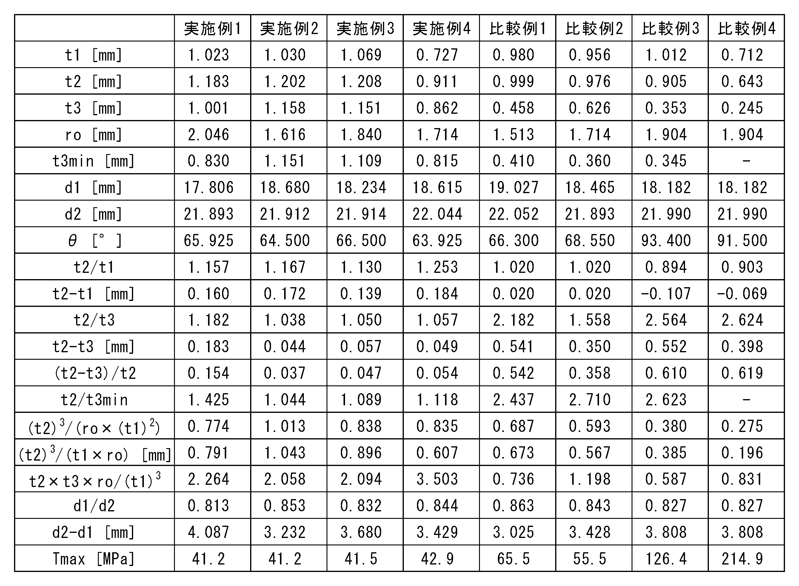
表1において、t1は側壁部の平均厚み、t2は接地部の平均厚み、t3は上げ底部の中心部における平均厚み、t3minは上げ底部の最小厚み、roは接地部の接地点から側壁部の外周面までの径方向距離、d1は側壁部の外径、d2は接地部の接地点により形成される円の直径、θは接地部の内表面の角度、Tmaxは落下衝撃により医薬容器用管ガラスの外表面に発生する最大引張応力(シミュレーション)をそれぞれ意味する。
表1の結果からも、実施例1~4に係る医薬容器用管ガラスでは、t2/t1が1.025超となっており、落下衝撃時に医薬容器用管ガラスの外表面に発生する最大引張応力Tmaxが50MPa以下と小さくなっていることが確認できる。一方、実施例1~4に係る医薬容器用管ガラスでは、t2/t1が1.025以下となっており、落下衝撃時に医薬容器用管ガラスの外表面に発生する最大引張応力Tmaxが50MPa超と大きくなっていることが確認できる。したがって、シミュレーション結果からも、比較例1~4に係る医薬容器用管ガラスでは落下破損が生じやすくなるが、実施例1~4に係る医薬容器用管ガラスでは落下破損が生じにくくなることが予想される。
そこで、実施例1~4及び比較例1~4に係る医薬容器用管ガラスに対して、実際に落下試験を行って破損本数を評価した。落下試験は、医薬容器用管ガラスの側壁部の外表面を案内するガイド筒内で、底部を下にした縦姿勢の医薬容器用管ガラスを450mmの高さからテフロン(登録商標)板上に落下させた。この落下試験を実施例1~4及び比較例1~4に係る医薬容器用管ガラスのそれぞれにつき20回(20本)ずつ行った。その結果を表2に示す。

表2に示すように、実際に行った落下試験でも、比較例1~4に係る医薬容器用管ガラスでは破損が生じる結果となったが、実施例1~4に係る医薬容器用管ガラスでは破損が生じないという良好な結果を得た。したがって、実際の落下試験でも、落下衝撃により生じる最大引張応力Tmaxのシミュレーション結果と同様の結果を得ることができた。
1 医薬容器用管ガラス
2 側壁部
3 底部
4 接地部
5 上げ底部
P 接地点
C 管軸中心線
X 径方向
Y 管軸方向
t1 側壁部の平均厚み
t2 接地部の平均厚み
t3 上げ底部の中心部における平均厚み
θ 接地部の内表面の角度
2 側壁部
3 底部
4 接地部
5 上げ底部
P 接地点
C 管軸中心線
X 径方向
Y 管軸方向
t1 側壁部の平均厚み
t2 接地部の平均厚み
t3 上げ底部の中心部における平均厚み
θ 接地部の内表面の角度
Claims (12)
- 円筒状の側壁部と、前記側壁部の一端部側を封止する底部と、を備える医薬容器用管ガラスであって、
前記底部は、前記側壁部の前記一端部に連結された接地部と、前記接地部の内側に設けられた上げ底部と、を備え、
前記側壁部の平均厚みt1[mm]と、前記接地部の平均厚みt2[mm]とが、
t2/t1>1.025
なる関係を満たすことを特徴とする医薬容器用管ガラス。 - 前記接地部の平均厚みt2[mm]と、前記上げ底部の中心部における平均厚みt3[mm]とが、
-0.8<(t2-t3)<0.5
なる関係を満たす請求項1に記載の医薬容器用管ガラス。 - 前記接地部の平均厚みt2[mm]と、前記上げ底部の中心部における平均厚みt3[mm]とが、
-0.8<(t2-t3)/t2<0.6
なる関係を満たす請求項1又は2に記載の医薬容器用管ガラス。 - 前記接地部の平均厚みt2[mm]と、前記上げ底部の最小厚みt3min[mm]とが、
0.4<t2/t3min<2.6
なる関係を満たす請求項1又は2に記載の医薬容器用管ガラス。 - 前記接地部の平均厚みt2[mm]と、前記接地部の接地点から前記側壁部の外周面までの径方向距離ro[mm]とが、
0.1≦(t2)3/(ro×(t1)2)≦8
なる関係を満たす請求項1又は2に記載の医薬容器用管ガラス。 - 前記側壁部の平均厚みt1[mm]と、前記接地部の平均厚みt2[mm]と、前記接地部の接地点から前記側壁部の外周面の仮想延長面までの径方向距離ro[mm]とが、
0.1≦(t2)3/(t1×ro)≦0.8
なる関係を満たす請求項1又は2に記載の医薬容器用管ガラス。 - 前記側壁部の外径d1[mm]と、前記接地部の接地点により形成される円の直径d2[mm]とが、
d2/d1≦0.86
なる関係を満たす請求項1又は2に記載の医薬容器用管ガラス。 - 前記接地部の平均厚みt2[mm]と、前記上げ底部の中心部における平均厚みt3[mm]と、前記接地部の接地点から前記側壁部の外周面の仮想延長面までの径方向距離ro[mm]とが、
t2×t3×ro/(t1)3>0.3
なる関係を満たす請求項1又は2に記載の医薬容器用管ガラス。 - 前記底部を下にした縦姿勢の前記医薬容器用管ガラスを450mmの高さからテフロン板上に落下させた場合に、前記医薬容器用管ガラスの外表面に発生する最大引張応力が55MPa以下である請求項1又は2に記載の医薬容器用管ガラス。
- 管軸方向の全長が、500mm以上である請求項1又は2に記載の医薬容器用管ガラス。
- 前記側壁部の両端部が封止されている請求項1又は2に記載の医薬容器用管ガラス。
- 請求項1又は2に記載の医薬容器用管ガラスを加工して、医薬用容器を製造することを特徴する医薬用容器の製造方法。
Priority Applications (1)
| Application Number | Priority Date | Filing Date | Title |
|---|---|---|---|
| CN202480073407.9A CN122228222A (zh) | 2023-12-19 | 2024-12-05 | 医药容器用管玻璃及医药容器的制造方法 |
Applications Claiming Priority (2)
| Application Number | Priority Date | Filing Date | Title |
|---|---|---|---|
| JP2023214030A JP2025097691A (ja) | 2023-12-19 | 2023-12-19 | 医薬容器用管ガラス及び医薬容器の製造方法 |
| JP2023-214030 | 2023-12-19 |
Publications (1)
| Publication Number | Publication Date |
|---|---|
| WO2025134792A1 true WO2025134792A1 (ja) | 2025-06-26 |
Family
ID=96136825
Family Applications (1)
| Application Number | Title | Priority Date | Filing Date |
|---|---|---|---|
| PCT/JP2024/043066 Pending WO2025134792A1 (ja) | 2023-12-19 | 2024-12-05 | 医薬容器用管ガラス及び医薬容器の製造方法 |
Country Status (3)
| Country | Link |
|---|---|
| JP (1) | JP2025097691A (ja) |
| CN (1) | CN122228222A (ja) |
| WO (1) | WO2025134792A1 (ja) |
Citations (3)
| Publication number | Priority date | Publication date | Assignee | Title |
|---|---|---|---|---|
| JP2019199396A (ja) * | 2018-05-18 | 2019-11-21 | ショット アクチエンゲゼルシャフトSchott AG | 改善された底部ジオメトリを備えたガラス容器 |
| US20210188687A1 (en) * | 2019-12-20 | 2021-06-24 | Schott Ag | Bottom forming process |
| US20240009078A1 (en) * | 2022-07-08 | 2024-01-11 | Schott Pharma Ag & Co. Kgaa | Glass containers for packaging salt or sugar-containing compositions in a frozen state |
-
2023
- 2023-12-19 JP JP2023214030A patent/JP2025097691A/ja active Pending
-
2024
- 2024-12-05 WO PCT/JP2024/043066 patent/WO2025134792A1/ja active Pending
- 2024-12-05 CN CN202480073407.9A patent/CN122228222A/zh active Pending
Patent Citations (3)
| Publication number | Priority date | Publication date | Assignee | Title |
|---|---|---|---|---|
| JP2019199396A (ja) * | 2018-05-18 | 2019-11-21 | ショット アクチエンゲゼルシャフトSchott AG | 改善された底部ジオメトリを備えたガラス容器 |
| US20210188687A1 (en) * | 2019-12-20 | 2021-06-24 | Schott Ag | Bottom forming process |
| US20240009078A1 (en) * | 2022-07-08 | 2024-01-11 | Schott Pharma Ag & Co. Kgaa | Glass containers for packaging salt or sugar-containing compositions in a frozen state |
Also Published As
| Publication number | Publication date |
|---|---|
| CN122228222A (zh) | 2026-06-16 |
| JP2025097691A (ja) | 2025-07-01 |
Similar Documents
| Publication | Publication Date | Title |
|---|---|---|
| CN215250411U (zh) | 玻璃容器 | |
| CN103517882B (zh) | 用于玻璃板再成形的方法和设备 | |
| EP2522641A2 (en) | Method for forming a vent port in a glass panel, and glass panel product manufactured using same | |
| CN107889484A (zh) | 基材真空成形模具和方法 | |
| JP2013536795A (ja) | ガラス基板を成形する装置及び方法 | |
| US9969642B2 (en) | One-press manufacturing method for glass container and glass container | |
| JP2021504283A5 (ja) | ||
| JP2025097691A (ja) | 医薬容器用管ガラス及び医薬容器の製造方法 | |
| TWI757989B (zh) | 罐容器 | |
| KR20100129872A (ko) | 유니버셜조인트의 크로스-스파이더 폐쇄 단조장치 및 그 방법 | |
| KR100813513B1 (ko) | 음극선관용 패널 | |
| CN117361859A (zh) | 底部形成工艺 | |
| CN107176782B (zh) | 玻璃热弯模具 | |
| JP6327319B2 (ja) | 金属管の製造方法及びその装置 | |
| CN107932886A (zh) | 一种制备大弧度弯管的设备及方法 | |
| JP3722457B2 (ja) | 陰極線管用ガラスパネル | |
| JP6957133B2 (ja) | ガラス成形レンズ、レンズ成形装置およびレンズ製造方法 | |
| KR20230020747A (ko) | 플렉시블 디스플레이용 커버 윈도우 | |
| JP6317617B2 (ja) | プレス成形用プリフォーム、及び、プレス成形用プリフォームの製造方法 | |
| CN1294613C (zh) | 阴极射线管的玻锥 | |
| JP5339106B2 (ja) | ガラスレンズのプレス成形方法 | |
| CN112585097B (zh) | 3d玻璃盖成型用模具及使用其的3d玻璃盖的制造方法 | |
| JP2013159347A (ja) | シュリンクラベル付きガラスびん | |
| EP3663216A1 (en) | Cylindrical body, container, and method for manufacturing container | |
| JP2006085994A (ja) | 陰極線管用ガラス物品及びその製造方法 |
Legal Events
| Date | Code | Title | Description |
|---|---|---|---|
| 121 | Ep: the epo has been informed by wipo that ep was designated in this application |
Ref document number: 24907178 Country of ref document: EP Kind code of ref document: A1 |