WO2025121237A1 - 乗物用シート - Google Patents
乗物用シート Download PDFInfo
- Publication number
- WO2025121237A1 WO2025121237A1 PCT/JP2024/042106 JP2024042106W WO2025121237A1 WO 2025121237 A1 WO2025121237 A1 WO 2025121237A1 JP 2024042106 W JP2024042106 W JP 2024042106W WO 2025121237 A1 WO2025121237 A1 WO 2025121237A1
- Authority
- WO
- WIPO (PCT)
- Prior art keywords
- seat cushion
- pair
- link
- seat
- cushion frame
- Prior art date
- Legal status (The legal status is an assumption and is not a legal conclusion. Google has not performed a legal analysis and makes no representation as to the accuracy of the status listed.)
- Pending
Links
Images





Classifications
-
- B—PERFORMING OPERATIONS; TRANSPORTING
- B60—VEHICLES IN GENERAL
- B60N—SEATS SPECIALLY ADAPTED FOR VEHICLES; VEHICLE PASSENGER ACCOMMODATION NOT OTHERWISE PROVIDED FOR
- B60N2/00—Seats specially adapted for vehicles; Arrangement or mounting of seats in vehicles
- B60N2/02—Seats specially adapted for vehicles; Arrangement or mounting of seats in vehicles the seat or part thereof being movable, e.g. adjustable
- B60N2/04—Seats specially adapted for vehicles; Arrangement or mounting of seats in vehicles the seat or part thereof being movable, e.g. adjustable the whole seat being movable
- B60N2/16—Seats specially adapted for vehicles; Arrangement or mounting of seats in vehicles the seat or part thereof being movable, e.g. adjustable the whole seat being movable height-adjustable
- B60N2/18—Seats specially adapted for vehicles; Arrangement or mounting of seats in vehicles the seat or part thereof being movable, e.g. adjustable the whole seat being movable height-adjustable the front or the rear portion of the seat being adjustable, e.g. independently of each other
Definitions
- the present invention relates to vehicle seats that can be installed in various types of vehicles.
- Patent Document 1 vehicle seats are known in which a seat cushion is supported via a pair of front and rear links (see, for example, Patent Document 1).
- the vehicle seat described in Patent Document 1 is configured to be able to change its posture between a relax mode in which the front part of the seat cushion is moved higher than the rear part, and a work mode in which both the front and rear parts are moved higher than the position of the seat cushion in drive mode.
- the vehicle seat includes a seat cushion that supports the buttocks of an occupant, and a change device that changes the inclination angle of the seat cushion's seat surface.
- the change device is configured to change the inclination angle so that the seat surface can be switched between a first position in which the seat surface is substantially horizontal or slopes downward toward the rear, and a second position in which the seat surface slopes upward toward the rear.
- the present invention allows the occupant to work in a forward-leaning position without placing the occupant in an uncomfortable position.
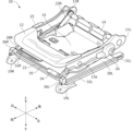
- FIG. 4 is a perspective view showing the structure of a seat cushion frame.
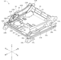
- FIG. 4 is a perspective view showing the structure of a seat cushion frame.
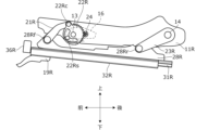
- FIG. 4 is a side view showing the lifting mechanism of the right side frame from the inside.
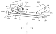
- FIG. 4 is a side view showing the lifting mechanism of the left side frame from the inside.
- FIG. FIG. 4 is a side view of the cushion side frame as viewed from the inside in the width direction.
- FIG. 4 is a side view of the cushion side frame as viewed from the inside in the width direction.
- FIG. 4 is a side view of the cushion side frame as viewed from the inside in the width direction.
- FIG. 4 is a side view of the cushion side frame as viewed from the inside in the width direction.
- FIG. 4 is a perspective view of a cover member attached to the front pipe.
- FIG. 4 is a plan view of the cover member attached to the front pipe.
- the vehicle seat according to the embodiment of the present invention can be applied to various vehicles, but below, an example of application to a vehicle, particularly a vehicle with an automatic driving function, i.e., an automatic driving vehicle, will be described.
- a vehicle to which the vehicle seat according to this embodiment is applied can run not only in an automatic driving mode in which no driving operation by the driver is required, but also in a manual driving mode in which the driver operates the vehicle.
- the vehicle to which the vehicle seat according to this embodiment is applied may be any of an engine vehicle having an internal combustion engine (engine) as a driving source, an electric vehicle having a driving motor as a driving source, and a hybrid vehicle having an engine and a driving motor as driving sources.
- FIG. 1 is a perspective view (as viewed diagonally from the front) of a vehicle seat (hereinafter simply referred to as a seat) 100 according to an embodiment of the present invention.
- the front-to-rear direction in FIG. 1 corresponds to the length of the vehicle
- the up-to-down direction corresponds to the height of the vehicle
- the left-to-right direction corresponds to the width of the vehicle.
- the front of the front-to-rear direction in FIG. 1 is the direction in which a passenger faces when in a riding position
- the left-to-right direction is the seat width direction
- the up-to-down direction is the seat height direction.
- the seat 100 is a vehicle seat used in the driver's seat or passenger seat of a vehicle, and includes a seat cushion 1 that supports the buttocks of an occupant, a seat back 2 that supports the back of the occupant, and a headrest 3 that is provided on the upper part of the seat back 2 and supports the head of the occupant.
- the seat cushion 1 extends in the front-rear and left-right directions and has a generally rectangular shape.
- the seat back 2 extends in the up-down and left-right directions and has a generally rectangular shape.
- the lower end of the seat back 2 is supported by the rear end of the seat cushion 1 via a pair of left and right reclining mechanisms 4 so that it can tilt in the front-rear direction with a shaft 4a extending in the left-right direction as a fulcrum.
- the reclining mechanisms 4 include a reclining actuator 4b, which will be described later.
- a controller 60 which will be described later, is provided under the cover of the seat cushion 1.
- FIG. 2A is a perspective view showing part of the seat frame inside the seat 100, more specifically, the structure of a frame (hereinafter referred to as the seat cushion frame) 10 that corresponds to the seat cushion 1.
- the seat cushion frame 10 is formed to fit the outer shape of the seat cushion 1.
- the seat cushion 1 is constructed by attaching a seat cushion pad made of a cushioning material such as urethane foam to the seat cushion frame 10, and then covering the outside of the seat cushion with a skin material made of synthetic leather, fabric, or the like.
- the seat cushion pad is supported by the seat cushion frame 10, and functions as a pressure-receiving part that receives the load from the occupant's buttocks.
- the seat cushion 1 includes a lifting device (hereinafter also referred to as a change device) 20 that changes the inclination angle of the seat cushion frame 10 so that the posture of the seat surface of the seat cushion 1 can be switched between three posture modes (drive mode, work mode, and relax mode) described below, and a slide device 30 that serves as a base member that supports the seat cushion frame 10 so that it can move in the front-rear direction.
- a lifting device hereinafter also referred to as a change device
- a slide device 30 that serves as a base member that supports the seat cushion frame 10 so that it can move in the front-rear direction.
- the slide device 30 is installed on the floor (body floor) below the seat 100 and extends in the front-rear direction.
- the seat cushion frame 10 is slidably engaged with the slide device 30, which allows the seat cushion 1 to move in the front-rear direction along the slide device 30 relative to the vehicle body.
- the seat cushion frame 10 comprises a pair of cushion side frames (hereinafter simply referred to as side frames) 11 (11L, 11R) arranged side by side, a cushion pan frame 12 that connects the front ends of the side frames 11L, 11R and covers the front of the side frames 11L, 11R, a metal front pipe 13 that connects the front parts of the side frames 11L, 11R behind the front end of the cushion pan frame 12, more preferably behind the front end of the cushion pan frame 12 and in front of the rear end of the cushion pan frame 12, a metal rear pipe 14 that connects the rear parts of the side frames 11L, 11R, and a pressure-receiving member 15 that is stretched across the front pipe 13 and rear pipe 14 and receives loads from above due to the weight of an occupant (seater). End caps 13a are attached to the right and left ends of the front pipe 13.
- the slide device 30 has a set of slide rails (hereinafter referred to as upper rails) 31 (31L, 31R) arranged side by side on the left and right, and a set of slide rails (hereinafter referred to as lower rails) 32 (32L, 32R) that are connected to the floor (body floor) via feet 19L, 19R and support the upper rails 31L, 31R so that they can move in the fore-and-aft direction.
- the slide device 30 also has a set of upper rail brackets 28 (28L, 28R) that are provided on the top surfaces of the upper rails 31L, 31R and connect the upper rails 31L, 31R to the side frames 11L, 11R.
- the slide device 30 has a rail connecting member 33 that connects the front ends of the lower rails 32L, 32R, a slide actuator (hereinafter also referred to as a rail actuator) 34 that is supported by the rail connecting member 33, a screw shaft 35 that rotates by the driving force of the slide actuator 34, and a pair of shaft support members 36 (36L, 36R) that are provided at the outer end of the screw shaft 35 in the seat width direction and support the screw shaft 35.
- a rail connecting member 33 that connects the front ends of the lower rails 32L, 32R
- a slide actuator 34 that is supported by the rail connecting member 33
- a screw shaft 35 that rotates by the driving force of the slide actuator 34
- a pair of shaft support members 36 36L, 36R
- the slide actuator 34 has a built-in electric motor and generates a driving force for rotating the screw shaft 35 via the electric motor.
- the shaft support member 36 has a gear box and transmits the rotational power of the screw shaft 35 via the gear box to a screw shaft (not shown) that extends in the front-rear direction inside the upper rail 31.
- the screw shaft of the upper rail 31 is arranged to pass through a ball screw (not shown) provided in the lower rail 32, and as the screw shaft of the upper rail 31 rotates, the upper rail 31 moves relative to the lower rail 32 in the front-rear direction.
- the slide device 30 functions as a slide mechanism.
- FIG. 2B is a perspective view showing the structure of the seat cushion frame 10 with the cushion pan frame 12 removed.
- the seat cushion frame 10 further includes a gear cover portion 16 that covers a part of the lifting device 20 (sector link 22R) in the seat width direction below the cushion pan frame 12, and an air conditioning unit 40 that sends air to the seating surface of the seat cushion frame 10 or draws air into the seating surface side.
- the gear cover portion 16 and the sector link 22R have insertion holes for inserting the front pipe 13.
- the front part of the gear cover portion 16 is attached to the right side frame 11R via the front pipe 13, and the rear end is joined to the inner wall surface of the side frame 11R.
- the sector link 22R is rotatably supported on the side frame 11R via the front pipe 13.
- the gear cover portion 16 is arranged so that the sector link 22R is positioned in the gap formed between the side frame 11R and the gear cover portion 16 in the seat width direction, i.e., so that it is located widthwise inward of the sector link 22R.
- the air conditioning unit 40 includes a blower 41, a blower bracket 42 that attaches the blower 41 to the cushion pan frame 12, and a duct 43 that extends from the blower 41 toward the seating surface and forms an airway that guides air from the blower 41 to the seating surface or from the seating surface to the blower 41.
- the end (supply/exhaust section) 43S of the duct 43 on the seating surface side is attached to a mounting port formed in the pressure-receiving member 15.
- FIG. 3 is a side view showing the lifting mechanism of the right side frame 11R from the inside.
- FIG. 4 is a side view showing the lifting mechanism of the left side frame 11L from the inside. As shown in FIG.
- the lifting device 20 includes a front link 21R having one end rotatably connected to the upper rail bracket 28R by a front support shaft 28Rf, a sector link 22R connected to the other end of the front link 21R by a link connection shaft 22Rc and connected to the front part of the side frame 11R via a front pipe (frame connection shaft) 13, a pinion gear 24 that can engage with a sector gear 22Rg formed on the rear surface of the sector link 22R, and a rear link 23R having one end rotatably connected to the upper rail bracket 28R by a rear support shaft 28Rr and the other end connected to the rear part of the side frame 11R via a rear pipe (rear connection shaft) 14.
- a front link 21R having one end rotatably connected to the upper rail bracket 28R by a front support shaft 28Rf
- a sector link 22R connected to the other end of the front link 21R by a link connection shaft 22Rc and connected to the front part of the side frame 11R via a front pipe (frame connection shaft)
- the gear cover portion 16 is indicated by a broken line in consideration of the ease of viewing the drawing.
- a stopper pin 22Rs is inserted into an opening provided in the sector link 22R, and when an end of the opening comes into contact with the stopper pin 22Rs, the rotation of the sector link 22R is restricted. In this manner, the stopper pin 22Rs is inserted into the opening, and the rotation range of the sector link 22R is restricted.
- the front link 21R is connected so that its front end is located rearward of the front end of the side frame 11R regardless of the posture mode of the seat cushion 1.
- the front link 21L is connected so that its front end is located rearward of the front end of the side frame 11L regardless of the posture mode of the seat cushion 1.
- the front link 21R and the sector link 22R are connected so that the link connection shaft 22Rc is positioned above the front pipe 13 regardless of the posture mode of the seat cushion 1, that is, so that the link connection shaft 22Rc moves above the front pipe 13 in a side view.
- the lifting device 20 includes a front link 21L, one end of which is rotatably connected to the upper rail bracket 28L by a front support shaft 28Lf, a support link 29, which is connected to the other end of the front link 21L by a link connection shaft 29c and is connected to the front of the side frame 11L via a front pipe (frame connection shaft) 13, a rear link (sector link) 22L, one end of which is rotatably connected to the upper rail bracket 28L by a rear support shaft 28Lr and the other end of which is connected to the rear of the side frame 11R via a rear pipe (rear connection shaft) 14, and a pinion gear 27 that can engage with a sector gear 22Rg formed on the front of the sector link 22L.
- FIG. 5 is a plan view of the seat cushion frame 10 with the cushion pan frame 12 removed.
- FIG. 6 is a rear view of the seat cushion frame 10 with the cushion pan frame 12 removed.
- the lifting device 20 further includes a front lifting actuator (hereinafter also simply referred to as the lifting actuator) 25 attached to the outer surface of the front part of the side frame 11R in the seat width direction, and a rear lifting actuator 26 (hereinafter also simply referred to as the lifting actuator) attached to the outer surface of the rear part of the side frame 11L in the seat width direction.
- the lifting actuator 25 incorporates an electric motor and generates a driving force for rotating the pinion gear 24 via the electric motor.
- the lifting actuator 26 incorporates an electric motor and generates a driving force for rotating the pinion gear 27 via the electric motor.
- the lifting actuators 25, 26 of the lifting device 20 and the slide actuator 34 of the slide device 30 are connected to the controller 60 by a wire harness (not shown) (hereinafter simply referred to as the harness), and the built-in motors are stopped or operated based on a control signal from the controller 60 received through the harness.
- the harness a wire harness (not shown) (hereinafter simply referred to as the harness)
- the controller 60 is provided on the left side of the seat cushion 1 as shown in FIG. 1, it is necessary to use the space below the seat cushion frame 10 to lead the harness from the controller 60 to the lifting actuator 25 provided on the right side of the seat cushion 1.
- the harness may be pulled or bent.
- the bent harness may interfere with a part of the seat cushion frame 10.
- a method of leading the harness by inserting the front pipe 13 from the controller 60 to the lifting actuator 25 can be considered.
- the end of the front pipe 13 may have unnecessary protrusions, so-called burrs, generated during processes such as cutting. Therefore, when a harness is inserted into the front pipe 13, the burrs on the end of the front pipe 13 may wear the surface of the harness or, in some cases, cause the harness to break. Therefore, in order to enable the harness to be routed through the front pipe 13, end caps 13a are attached to the ends (right and left ends) of the front pipe 13 as shown in Figures 2A and 2B.
- Figure 7 is a cross-sectional view of the end cap 13a.
- Figures 8A to 8C are side views of the side frame 11R as viewed from the inside in the width direction. Note that, to simplify the explanation, the cushion pan frame 12 and gear cover portion 16 are omitted from Figures 8A to 8C.
- the position of the seat 100 can be changed to multiple modes, such as a drive mode that puts the occupant in a position suitable for driving when the vehicle is normally running, a work mode that puts the occupant in a position that makes it easy to work while the vehicle is parked or in automatic running, and a relax mode that tilts the seat back 2 to put the occupant in a position that makes it easy to lie down.
- the lifting device 20 rotates the pinion gears 24, 27 via the lifting actuators 25, 26 to change the posture of the seat surface of the seat cushion 1 (hereinafter, sometimes simply referred to as the posture of the seat cushion 1) to correspond to each mode. More specifically, it changes the inclination angle of the seat surface of the seat cushion 1.
- the pinion gear 24 rotates, the meshing position between the pinion gear 24 and the sector gear 22Rg changes. This causes the sector link 22R to swing, and in conjunction with this, the front link 21R connected to the sector link 22R rotates around the front support shaft 28Rf. Furthermore, the front link 21L connected to the support link 29 journaled via the front pipe (frame connecting shaft) 13 at a position opposite the sector link 22R in the seat width direction rotates.
- FIG. 8A is a side view of the seat cushion 1 in drive mode.
- the lifting device 20 adjusts the meshing position between the pinion gear 24 and the sector gear 22Rg, and the meshing position between the pinion gear 27 and the sector gear 22Lg so that the posture of the seat cushion 1 is approximately horizontal or has a downward slope toward the rear, more specifically, so that the side frame 11 is approximately parallel to the upper rail 31 of the slide device 30 in a side view.
- the upper rail 31 is moved relative to the lower rail 32 in the fore-aft direction via the slide actuator 34 to adjust the position of the seat cushion 1 (fore-aft position) so that the seat occupant can assume a driving posture that makes it easy to operate the steering wheel, accelerator pedal, brake pedal, etc.
- FIG. 8B is a side view of the seat cushion 1 in the work mode.
- the lifting device 20 adjusts the meshing position between the pinion gear 24 and the sector gear 22Rg and the meshing position between the pinion gear 27 and the sector gear 22Lg so that the posture of the seat cushion 1 is upwardly inclined toward the rear as shown in FIG. 8B, more specifically, so that the height of the front part of the side frame 11 relative to the upper rail 31 is lower than in the drive mode, and the height of the rear part of the side frame 11 relative to the upper rail 31 is higher than in the drive mode.
- the upper rail 31 is moved rearward via the slide actuator 34 from the drive mode to adjust the position of the seat cushion 1 (front-rear position) so that the space at the feet of the seated person is secured, more specifically, so that sufficient space is secured between the legs (thighs) of the seated person and the bottom of the dashboard of the vehicle when the posture of the seat cushion 1 is in the state shown in FIG. 8B.
- the blower bracket 42 is attached to the cushion pan frame 12 so that its front end is located at least rearward of the rear end of the rail connecting member 33 in the front-rear direction, more specifically, in the extension direction of the upper rail 31 (or the lower rail 32) in the work mode.
- the blower bracket 42 is formed so that its lower surface (more specifically, the support surface that supports the blower 41) is inclined downward toward the rear. By making the support surface an inclined surface in this way, a sufficient gap can be provided between the duct 43 and the front pipe 13 in the vertical direction. As a result, it is possible to provide the blower bracket 42 so as to be located rearward of the rear end of the rail connecting member 33 while avoiding interference between the duct 43 and the front pipe 13. As shown in FIG.
- the lower end of the duct 43 in the work mode, the lower end of the duct 43 is located below the upper ends of the slide rails 31 and 32, so that a part of the air conditioner 40 overlaps with the slide rails 31 and 32 in the vertical direction in a side view.
- the front part of the side frame 11 can be lowered to the height of FIG. 8B without interfering with the air conditioner 40 and the slide rails 31 and 32.
- the blower bracket 42 is attached to the cushion pan frame 12 so that the position of the link connecting shaft 22Rc is higher than the blower bracket 42 in the work mode.
- FIG. 8C is a side view of the seat cushion 1 in the relax mode.
- the posture of the seat cushion 1 is downwardly inclined at a larger angle toward the rear than in the drive mode, more specifically, the height of the front part of the side frame 11 relative to the upper rail 31 is higher than in the drive mode, and the height of the rear part of the side frame 11 relative to the upper rail 31 is lower than in the drive mode.
- the upper rail 31 is moved rearward via the slide actuator 34 from the drive mode to adjust the position of the seat cushion 1 (front-rear position) so that the space at the feet of the seated person is secured, more specifically, so that the knees and feet of the seated person do not come into contact with the steering wheel or the lower part of the dashboard of the vehicle when the seated person lies down by tilting the seat back 2.
- the sector link 22R is covered by the gear cover portion 16 in the seat width direction, but is not completely covered in the vertical direction. Specifically, a part of the sector link 22R is exposed above the gear cover portion 16. Therefore, the exposed part may come into contact with the seat cushion pad attached to the seat cushion frame 10.
- the sector gear 22Rg is located above the sector link 22R, so a part of the sector gear 22Rg is exposed. If the sector link 22R swings in this state, the sector gear 22Rg may catch the seat cushion pad. Therefore, a cover member 50 that covers the sector link 22R in the vertical direction is attached to the right part of the front pipe 13.
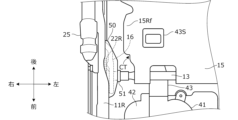
- Figure 9A is a perspective view of the cover member 50 attached to the front pipe 13.
- Figure 9B is a plan view of the cover member 50 attached to the front pipe 13.
- the cover member 50 is molded from resin or the like, and a bearing portion 51 that engages with the front pipe 13 is formed on the left side of the front part of the cover member 50, as shown in Figures 9A and 9B.
- the bearing portion 51 is pushed in from above the front pipe 13 to engage the bearing portion 51 with the front pipe 13.
- a step portion (cutout portion) CT is formed in the front portion of the front wing portion 15Rf.
- the step portion CT is not limited to the shape shown in FIG. 9B and may have other shapes. For example, if a cover member having a different shape from the cover member 50 is attached instead of the cover member 50, the step portion CT may be formed to match the planar shape of the exterior portion of that cover member.
- the seat 100 includes a seat cushion 1 that supports the buttocks of an occupant, and a lifting device 20 as a change device that changes the inclination angle of the seat surface of the seat cushion 1.
- the lifting device 20 is configured to change the inclination angle so that the posture of the seat surface of the seat cushion 1 can be switched between a first posture (posture in FIG. 8A ) in which the posture is substantially horizontal or has a downward slope toward the rear, and a second posture (posture in FIG. 8B ) in which the posture has an upward slope toward the rear.
- the seat cushion 1 has a seat cushion frame 10 that can move together with the seat surface.
- the lifting device 20 has a first support portion (front link 21L, front link 21R, and sector link 22R) that supports a front end portion of the seat cushion frame 10 so that it can be raised and lowered, and a second support portion (rear links 22L, 23R) that supports a rear end portion of the seat cushion frame 10 so that it can be raised and lowered.
- the first support portion supports the front end of the seat cushion frame 10 so that the height of the front end of the seat cushion frame 10 can be changed between a first front end height (the height of the front end of the side frame 11R in FIG. 8A) corresponding to the first posture, and a second front end height (the height of the front end of the side frame 11R in FIG. 8B) lower than the first front end height.
- the second support portion supports the rear end of the seat cushion frame 10 so that the height of the rear end of the seat cushion frame 10 can be changed between a first rear end height (the height of the rear end of the side frame 11R in FIG. 8A) corresponding to the first posture, and a second rear end height (the height of the rear end of the side frame 11R in FIG. 8B) higher than the first rear end height.
- a first rear end height the height of the rear end of the side frame 11R in FIG. 8A
- a second rear end height the height of the rear end of the side frame 11R in FIG. 8B
- the first support portion further supports the front end of the seat cushion frame 10 so that the height of the front end of the seat cushion frame 10 can be changed to a third front end height (the height of the front end of the side frame 11R in FIG. 8C) that is higher than the first front end height.
- the second support portion further supports the rear end of the seat cushion frame 10 so that the height of the rear end of the seat cushion frame 10 can be changed to a third rear end height (the height of the rear end of the side frame 11R in FIG. 8C) that is lower than the first rear end height.
- the lifting device 20 is configured to be able to change the inclination angle so that the posture of the seat surface of the seat cushion 1 can be switched between a first posture, a second posture, and a third posture (the posture in FIG. 8C) that has a downward slope toward the rear at an inclination angle larger than the inclination angle in the first posture. This configuration allows the occupant to not only work but also take a nap or lie down to rest while parking or during automatic driving.
- the seat 100 further includes upper rail brackets 28L, 28R as support members that support the seat cushion frame 10.
- the first support portion includes a front link 21R as a first link whose front end is connected to a front portion of the upper rail bracket 28R and which is rotatable in the vertical direction relative to the connection portion with the upper rail bracket 28R, and a sector link 22R as a second link which is connected to a rear end of the front link 21R and to a front portion of the seat cushion frame 10 and which is rotatable in the vertical direction around a connection portion with the seat cushion frame 10 (link connection shaft 22Rc in FIG. 3).
- the front link 21R is arranged so that the front end of the front link 21R is located rearward of the front end of the seat cushion frame 10 when it rotates relative to the connection portion with the upper rail bracket 28R.
- the lifting device 20 further has a pinion gear 24 as a first pinion gear that rotates around a rotation axis along the seat width direction
- the sector link 22R has a sector gear 22Rg formed on a part of its outer circumferential surface that engages with the pinion gear 24 so that it can rotate in conjunction with the rotation of the pinion gear 24.
- the front link 21R and the sector link 22R are arranged so that the connection between the front link 21R and the sector link 22R moves above the connection between the sector link 22R and the seat cushion frame 10 (front pipe (frame connection shaft) 13 in FIG. 3). This allows for a compact seat cushion (seat cushion frame) that allows the seat position to be changed by the link.
- the upper rail brackets 28L, 28R are equipped with a slide device 30 that moves the seat cushion frame 10 in the fore-and-aft direction.
- the seat cushion frame 10 has a pair of left and right side frames 11L, 11R extending in the fore-and-aft direction.
- the slide device 30 has a pair of left and right upper rails 31L, 31R corresponding to the pair of left and right side frames 11L, 11R, and a pair of left and right lower rails 32L, 32R that support the pair of left and right upper rails 31L, 31R movably in the fore-and-aft direction.
- the lifting device 20 has a pair of left and right first support portions that support the front ends of the pair of left and right side frames 11L, 11R, and a pair of left and right second support portions that support the rear ends of the pair of left and right side frames.
- Each of the pair of left and right first support parts has a pair of left and right first links (front link 21L and front link 21R) whose front ends are connected to the front parts of the pair of left and right upper rails 31L, 31R, and a pair of left and right second links (support link 29 and sector link 22R) that are connected to rear ends of the pair of left and right first links and connect the pair of left and right first links to front parts of the pair of left and right side frames 11L, 11R.
- a sector gear is formed in one of the pair of left and right second links (sector link 22R), and the pinion gear 24 is provided in the front part of the side frame 11R of the pair of left and right side frames 11L, 11R that corresponds to the second link (sector link 22R) on which the sector gear is formed.
- the lifting device 20 further includes a pinion gear 27 as a second pinion gear rotating around a rotation axis along the seat width direction at the rear of the side frame 11L not provided with the pinion gear 24 among the pair of left and right side frames 11L, 11R.
- Each of the pair of left and right second support parts includes a pair of left and right third links (sector link 22L and rear link 23R) whose front ends are connected to the rear parts of the pair of left and right upper rails 31L, 31R and whose rear ends are connected to the rear parts of the pair of left and right side frames 11L, 11R.
- a sector gear that engages with the pinion gear 27 is formed on a part of the outer circumferential surface of the third link (sector link 22L) connected to the side frame 11L provided with the pinion gear 27 so that the third link rotates in the vertical direction relative to the connecting part (rear pipe (rear connecting shaft) 14) with the side frame 11L in conjunction with the rotation of the pinion gear 27.
- the above embodiment can be modified in various ways. Modifications are described below.
- the front end of the seat cushion frame 10 can be changed to three different heights (first front end height (FIG. 8A), second front end height (FIG. 8B), and third front end height (FIG. 8C)).
- the rear end of the seat cushion frame 10 can be changed to three different heights (first rear end height (FIG. 8A), second rear end height (FIG. 8B), and third rear end height (FIG. 8C)).
- the heights of the front and rear ends of the seat cushion frame 10 may be changed in a number of steps other than three, for example, in a number of steps greater than three.
- the seat surface of the seat cushion 1 may be switchable to a posture mode other than the three posture modes shown in FIGS. 8A to 8C.
- the driving force for rotating the pinion gears 24, 27 is generated by the electric motors of the lifting actuators 25, 26.
- the pinion gears 24, 27 may be rotated by manual operation via an operating lever or dial provided on the side of the seat 100. That is, the passenger (seater) may be able to change the posture of the seat surface of the seat cushion 1 by operating an operating lever or dial.
- the driving force for rotating the screw shaft 35 is generated by the electric motor of the slide actuator 34, and the upper rail 31 is slidably moved relative to the lower rail 32.
- the upper rail 31 may be slidably moved relative to the lower rail 32 manually.
- the upper rail 31 may be slidably moved relative to the lower rail 32 by operating a slide operating lever (not shown) extending left and right provided below the front part of the seat 100.
- the rail connecting member 33 connects the front ends of the lower rails 32L and 32R, but the rail connecting member may connect the rear ends of the lower rails 32L and 32R. That is, the rail connecting member, slide actuator, screw shaft, and shaft support member may be disposed at the rear ends of the lower rails 32L and 32R.
Landscapes
- Engineering & Computer Science (AREA)
- Aviation & Aerospace Engineering (AREA)
- Transportation (AREA)
- Mechanical Engineering (AREA)
- Seats For Vehicles (AREA)
Abstract
乗物用シートは、乗員の臀部を支持するシートクッションと、シートクッションの座面の傾斜角を変更する昇降装置と、を備える。変更装置は、シートクッションの座面の姿勢が、略水平または後方にかけて下り勾配 となる第1姿勢と、後方にかけて上り勾配となる第2姿勢と、の間で切り換わるように傾斜角を変更可能に構成される。
Description
本発明は、各種乗り物に搭載される乗物用シートに関する。
従来、前後一対のリンクを介してシートクッションを支持する乗物用シートが知られている(例えば特許文献1参照)。上記特許文献1記載の乗物用シートは、シートクッションの前部を後部よりも上方に移動させたリラックスモードと、前部と後部の双方をドライブモードにおけるシートクッションの位置よりも上方に移動させたワークモードとに、姿勢変更可能に構成される。
ところで、駐車中や自動運転で走行中に、前傾姿勢で作業を行いたいというニーズがある。しかしながら、シートバックを前傾させると、乗員の姿勢が窮屈になり、好ましい作業姿勢を得ることが難しい。
本発明の一態様である乗物用シートは、乗員の臀部を支持するシートクッションと、シートクッションの座面の傾斜角を変更する変更装置と、を備える。変更装置は、座面の姿勢が、略水平または後方にかけて下り勾配となる第1姿勢と、後方にかけて上り勾配となる第2姿勢と、の間で切り換わるように傾斜角を変更可能に構成される。
本発明によれば、着座者を窮屈な姿勢にすることなく着座者の前傾姿勢での作業を可能にする。
以下、図面を参照して本発明の実施の形態について説明する。本発明の実施の形態に係る乗物用シートは、種々の乗物に対して適用することができるが、以下では、車両、特に自動運転機能を有する車両、すなわち自動運転車両に適用する例を説明する。本実施形態に係る乗物用シートが適用される車両は、ドライバによる運転操作が不要な自動運転モードでの走行だけでなく、ドライバの運転操作による手動運転モードでの走行も可能である。なお、本実施形態に係る乗物用シートが適用される車両は、内燃機関(エンジン)を走行駆動源として有するエンジン車両、走行モータを走行駆動源として有する電気自動車、エンジンと走行モータとを走行駆動源として有するハイブリッド車両のいずれであってもよい。
図1は、本発明の実施の形態に係る乗物用シート(以下、単にシートと呼ぶ。)100の斜視図(斜め前方から見た図)である。図1の前後方向は車両の長さ方向に相当し、上下方向は車両の高さ方向に相当し、左右方向は車幅方向に相当する。換言すると、図1の前後方向のうち前方は、乗車姿勢の乗員が向く方向であり、左右方向はシート幅方向であり、上下方向はシート高さ方向である。
図1に示すように、シート100は、車両の運転席や助手席などで使用される車両用シートであり、乗員の臀部を支持するシートクッション1と、乗員の背部を支持するシートバック2と、シートバック2の上部に設けられ、乗員の頭部を支持するヘッドレスト3とを備える。シートクッション1は、前後方向および左右方向に延在し、全体が略矩形状を呈する。シートバック2は、上下方向および左右方向に延在し、全体が略矩形状を呈する。シートバック2の下端部は、左右一対のリクライニング機構4を介してシートクッション1の後端部に、左右方向に延在する軸部4aを支点にして前後方向に傾動可能に支持される。リクライニング機構4は、後述するリクライニングアクチュエータ4bを備える。シートクッション1の表皮の下側には、後述するコントローラ60が設けられている。
図2Aは、シート100の内部のシートフレームの一部、より詳細には、シートクッション1に対応するフレーム(以下、シートクッションフレームと呼ぶ。)10の構造を示す斜視図である。シートクッションフレーム10は、シートクッション1の外形形状に沿って形成される。シートクッション1は、図1に示すように、シートクッションフレーム10に、ウレタンフォームなどのクッション材からなるシートクッションパッドを取り付け、さらにその外側に、合成皮革や布地などからなる表皮材を被せることで構成される。シートクッションパッドは、シートクッションフレーム10により支持され、乗員の臀部からの荷重を受ける受圧部として機能する。
シートクッション1は、シートクッション1の座面の姿勢が後述する3つの姿勢モード(ドライブモードとワークモードとリラックスモード)の間で切り換わるようシートクッションフレーム10の傾斜角を変更する昇降装置(以下、変更装置とも呼ぶ。)20と、シートクッションフレーム10を前後方向に移動可能に支持するベース部材としてのスライド装置30と、を備える。昇降装置20およびスライド装置30の詳細については後述する。
スライド装置30は、図2Aに示すように、シート100の下方のフロア(車体床部)に、前後方向に沿って延設される。シートクッションフレーム10は、スライド装置30にスライド可能に係合され、これによりシートクッション1が車体に対しスライド装置30に沿って前後方向に移動可能である。
シートクッションフレーム10は、左右に並ぶ一組のクッションサイドフレーム(以下、単にサイドフレームと呼ぶ。)11(11L,11R)と、サイドフレーム11L,11Rの前端部を連結しサイドフレーム11L,11Rの前方を覆うクッションパンフレーム12と、クッションパンフレーム12の前端部よりも後方において、より好適には、クッションパンフレーム12の前端部よりも後方かつクッションパンフレーム12の後端部よりも前方において、サイドフレーム11L,11Rの前部どうしを連結する金属製のフロントパイプ13と、サイドフレーム11L,11Rの後部どうしを連結する金属製のリアパイプ14と、フロントパイプ13およびリアパイプ14に掛け渡され、乗員(着座者)の重量等による上方からの荷重を受ける受圧部材15と、を備える。フロントパイプ13の右端部および左端部には、エンドキャップ13aが取り付けられる。
スライド装置30は、左右に並んで配置された一組のスライドレール(以下、アッパレールと呼ぶ。)31(31L,31R)と、フット19L,19Rを介してフロア(車体床部)に結合され、アッパレール31L,31Rを前後方向へ移動可能に支持する一組のスライドレール(以下、ロアレールと呼ぶ。)32(32L,32R)とを有する。また、スライド装置30は、アッパレール31L,31Rの上面に設けられ、アッパレール31L,31Rとサイドフレーム11L,11Rとを連結する一組のアッパレールブラケット28(28L,28R)を有する。さらに、スライド装置30は、ロアレール32L,32Rの前端部を連結するレール連結部材33と、レール連結部材33に支持されるスライドアクチュエータ(以下、レールアクチュエータとも呼ぶ。)34と、スライドアクチュエータ34の駆動力により回転するスクリューシャフト35と、スクリューシャフト35のシート幅方向における外端部に設けられ、スクリューシャフト35を支持する一組のシャフト支持部材36(36L,36R)と、を有する。
スライドアクチュエータ34は、電動モータを内蔵し、該電動モータを介してスクリューシャフト35を回転させるための駆動力を発生させる。シャフト支持部材36は、ギヤボックスを有し、スクリューシャフト35の回転動力を、ギヤボックスを介して、アッパレール31の内部に前後方向に沿って延設された不図示のスクリューシャフトに伝達する。アッパレール31のスクリューシャフトは、ロアレール32に設けられた不図示のボールねじを挿通するように設けられていて、アッパレール31のスクリューシャフトが回転することで、アッパレール31がロアレール32に対して前後方向に相対移動する。スライド装置30は、このような構成によりスライド機構としての機能を発揮する。
図2Bは、クッションパンフレーム12が外されたシートクッションフレーム10の構造を示す斜視図である。図2Bに示すように、シートクッションフレーム10はさらに、クッションパンフレーム12の下方において、昇降装置20の一部(セクタリンク22R)をシート幅方向において覆うギヤカバー部16と、シートクッションフレーム10の着座面に対して空気を送る、または着座面側の空気を吸い込む空調装置40と、を備える。
ギヤカバー部16およびセクタリンク22Rには、フロントパイプ13を挿通させるための挿通孔が形成されている。ギヤカバー部16の前部は、フロントパイプ13を介して右側のサイドフレーム11Rに取り付けられ、後端部は、サイドフレーム11Rの内壁面に接合される。セクタリンク22Rは、フロントパイプ13を介してサイドフレーム11Rに回転自在に軸支される。ギヤカバー部16は、シート幅方向においてセクタリンク22Rがサイドフレーム11Rとギヤカバー部16との間に形成された隙間内に配置されるように、すなわち、セクタリンク22Rよりも幅方向内側になるように設けられる。
空調装置40は、ブロア41と、ブロア41をクッションパンフレーム12に取り付けるブロアブラケット42と、ブロア41から着座面側に延在するとともに、ブロア41から着座面へまたは着座面からブロア41へ空気を導く気道を形成するダクト43と、を備える。ダクト43の着座面側の端部(給排部)43Sは、受圧部材15に形成された取付口に取り付けられる。
ここで、昇降装置20の構成を説明する。図3は、右側のサイドフレーム11Rの昇降機構を内側から示す側面図である。図4は、左側のサイドフレーム11Lの昇降機構を内側から示す側面図である。昇降装置20は、図3に示すように、一方の端部がフロント支軸28Rfによってアッパレールブラケット28Rと回転可能に連結されるフロントリンク21Rと、リンク連結軸22Rcによってフロントリンク21Rの他方の端部と連結されるとともにフロントパイプ(フレーム連結軸)13を介してサイドフレーム11Rの前部と連結されるセクタリンク22Rと、セクタリンク22Rの後面に形成されたセクタギヤ22Rgと係合可能なピニオンギヤ24と、一方の端部がリア支軸28Rrによってアッパレールブラケット28Rと回転可能に連結され、他方の端部がリアパイプ(リア連結軸)14を介してサイドフレーム11Rの後部と連結されるリアリンク23Rと、を備える。図3では、図面の見やすさを考慮して、ギヤカバー部16を破線で示している。セクタリンク22Rに設けられた開口部には、ストッパピン22Rsが挿通され、開口部の端部とストッパピン22Rsとが当接すると、セクタリンク22Rの回動が規制される。このように、開口部にストッパピン22Rsが挿通されることで、セクタリンク22Rの回動範囲が規制される。なお、フロントリンク21Rは、シートクッション1がいずれの姿勢モードであってもその前端部がサイドフレーム11Rの前端部よりも後方に位置するように接続される。また、フロントリンク21Lは、シートクッション1がいずれの姿勢モードであってもその前端部が、サイドフレーム11Lの前端部よりも後方に位置するように接続される。また、シートクッション1がいずれの姿勢モードであってもリンク連結軸22Rcがフロントパイプ13よりも上方に位置するように、すなわち、側面視においてリンク連結軸22Rcがフロントパイプ13よりも上方を移動するように、フロントリンク21Rとセクタリンク22Rとが連結される。
また、昇降装置20は、図4に示すように、一方の端部がフロント支軸28Lfによってアッパレールブラケット28Lと回転可能に連結されるフロントリンク21Lと、リンク連結軸29cによってフロントリンク21Lの他方の端部と連結されるとともにフロントパイプ(フレーム連結軸)13を介してサイドフレーム11Lの前部と連結されるサポートリンク29と、一方の端部がリア支軸28Lrによってアッパレールブラケット28Lと回転可能に連結され、他方の端部がリアパイプ(リア連結軸)14を介してサイドフレーム11Rの後部と連結されるリアリンク(セクタリンク)22Lと、セクタリンク22Lの前面に形成されたセクタギヤ22Rgと係合可能なピニオンギヤ27とを備える。
図5は、クッションパンフレーム12が外されたシートクッションフレーム10の平面図である。図6は、クッションパンフレーム12が外されたシートクッションフレーム10の背面図である。昇降装置20は、図5および図6に示すように、さらに、サイドフレーム11Rの前部のシート幅方向における外面に取り付けられる前部昇降アクチュエータ(以下、単に昇降アクチュエータとも呼ぶ。)25と、サイドフレーム11Lの後部のシート幅方向における外面に取り付けられる後部昇降アクチュエータ26(以下、単に昇降アクチュエータとも呼ぶ。)と、を備える。昇降アクチュエータ25は、電動モータを内蔵し、該電動モータを介してピニオンギヤ24を回転させるための駆動力を発生させる。同様に、昇降アクチュエータ26は、電動モータを内蔵し、該電動モータを介してピニオンギヤ27を回転させるための駆動力を発生させる。
なお、昇降装置20の昇降アクチュエータ25,26とスライド装置30のスライドアクチュエータ34は、不図示のワイヤハーネス(以下、単にハーネスと呼ぶ。)によりコントローラ60と接続され、ハーネスを介して受信されるコントローラ60からの制御信号に基づいて内蔵モータを停止または作動させる。一方で、図1のようにコントローラ60がシートクッション1の左部に設けられている場合、シートクッションフレーム10の下方の空間を利用して、コントローラ60からシートクッション1の右部に設けられた昇降アクチュエータ25へハーネスを導く必要がある。しかしながら、そのようにハーネスを取り回すと、シートクッションフレーム10のスライド動作等によりコントローラ60と昇降アクチュエータ25との距離が変動した場合に、ハーネスが引っ張られたり撓んだりするおそれがある。また、撓んだハーネスがシートクッションフレーム10の一部と干渉するおそれがある。このようなハーネスへの影響を回避する手段として、コントローラ60から昇降アクチュエータ25へとフロントパイプ13を挿通させてハーネスを導く方法が考えられる。しかしながら、フロントパイプ13の端部には、切削加工等の工程で発生した不要な突起、いわゆるバリが存在する場合がある。したがって、ハーネスをフロントパイプ13に挿通させて使用すると、フロントパイプ13の端部のバリによってハーネスの表面が摩耗したり、場合によってはハーネスが切断したりするおそれがある。そこで、フロントパイプ13を介したハーネスの取り回しを可能とするように、フロントパイプ13には、図2Aおよび図2Bに示すように、その端部(右端部および左端部)に、エンドキャップ13aが取り付けられている。図7は、エンドキャップ13aの断面図である。フロントパイプ13の端部に図7に示すようなエンドキャップ13aを装着することで、フロントパイプ13の端部のバリとハーネスとの接触を防止できる。これにより、フロントパイプ13を介した、シートクッションフレーム10のシート幅方向の一方側から他方側へのハーネスの取り回しが可能となる。
次いで、図8A~図8Cを用いて、昇降装置20によるシートクッション1の姿勢変更について説明する。図8A~図8Cは、サイドフレーム11Rを幅方向内側から見た側面図である。なお、図8A~図8Cでは、説明の簡略化のため、クッションパンフレーム12およびギヤカバー部16の図示を省略している。シート100は、車両の通常走行時に着座者を操縦に適した姿勢にするドライブモード、駐車中や自動走行時に着座者を作業等がしやすい姿勢にするワークモード、シートバック2を傾倒させることで着座者を横になりやすい姿勢にするリラックスモード等の複数のモードに姿勢変更可能である。
昇降装置20は、昇降アクチュエータ25,26を介してピニオンギヤ24,27を回転させて、各モードに対応させるようにシートクッション1の座面の姿勢(以下、単にシートクッション1の姿勢と表現する場合がある。)を変更する。より具体的には、シートクッション1の座面の傾斜角を変更する。ピニオンギヤ24が回転すると、ピニオンギヤ24とセクタギヤ22Rgとの噛み合い位置が変化する。これにより、セクタリンク22Rが揺動し、それに連動して、セクタリンク22Rに連結されたフロントリンク21Rがフロント支軸28Rfを中心に回動する。さらに、セクタリンク22Rとシート幅方向の対向する位置でフロントパイプ(フレーム連結軸)13を介して軸支されたサポートリンク29に連結された、フロントリンク21Lが回動する。また、ピニオンギヤ27が回転すると、ピニオンギヤ27とセクタギヤ22Lgとの噛み合い位置が変化する。これにより、セクタリンク22Lが揺動し、それに連動して、セクタリンク22Lとシート幅方向の対向する位置でリアパイプ(リア連結軸)14を介して回動可能に軸支されたリアリンク23Rが回動する。各リンク21R,21L,22R,22L,23R,29の以上のような動作によってシートクッション1の座面の傾斜角が調整される。
図8Aは、ドライブモードにおけるシートクッション1の側面図である。ドライブモードでは、図8Aに示すようにシートクッション1の姿勢が略水平または後方にかけて下り勾配となるように、より詳細には、サイドフレーム11がスライド装置30のアッパレール31と側面視で略平行になるように、昇降装置20は、ピニオンギヤ24とセクタギヤ22Rgとの噛み合い位置、および、ピニオンギヤ27とセクタギヤ22Lgとの噛み合い位置を調整する。また、ドライブモードでは、着座者がステアリングハンドルや、アクセルペダル、ブレーキペタル等を操作しやすい運転姿勢をとれるように、スライドアクチュエータ34を介してアッパレール31をロアレール32に対して前後方向に相対移動させて、シートクッション1の位置(前後方向の位置)を調整する。
図8Bは、ワークモードにおけるシートクッション1の側面図である。ワークモードでは、図8Bに示すようにシートクッション1の姿勢が後方にかけて上り勾配となるように、より詳細には、サイドフレーム11の前部のアッパレール31に対する高さをドライブモード時よりも低くするように、かつ、サイドフレーム11の後部のアッパレール31に対する高さをドライブモード時よりも高くするように、昇降装置20は、ピニオンギヤ24とセクタギヤ22Rgとの噛み合い位置、および、ピニオンギヤ27とセクタギヤ22Lgとの噛み合い位置を調整する。また、ワークモードでは、着座者の足元のスペースが確保されるように、より詳細には、シートクッション1の姿勢が図8Bの状態であるときに着座者の脚部(大腿部)と車両のダッシュボードの下部との間に十分なスペースが確保されるように、スライドアクチュエータ34を介してアッパレール31をドライブモード時よりも後方に移動させて、シートクッション1の位置(前後方向の位置)を調整する。
ワークモードにおいて、サイドフレーム11の前部のアッパレール31に対する高さを低くすると、レール連結部材33やスクリューシャフト35が配置される位置によっては、ブロアブラケット42の前端部とレール連結部材33やスクリューシャフト35とが干渉するおそれがある。このような干渉を避けるように、ブロアブラケット42は、ワークモードのときにその前端部が前後方向において、より詳細には、アッパレール31(またはロアレール32)の延在方向において少なくともレール連結部材33の後端部よりも後方に位置するように、クッションパンフレーム12に取り付けられる。一方で、ブロアブラケット42の前端部とレール連結部材33の後端部との干渉を回避するようにブロアブラケット42を後方に配置した場合、ダクト43がフロントパイプ13と干渉するおそれがある。そこで、図8B等に示すように、ブロアブラケット42は、その下面(より具体的にはブロア41を支持する支持面)が後方にかけて下方へ傾斜するように形成される。このように支持面を傾斜面とすることで、上下方向においてダクト43とフロントパイプ13との間に十分な隙間を設けることができる。その結果、ダクト43とフロントパイプ13との干渉を回避しつつ、ブロアブラケット42をレール連結部材33の後端部よりも後方に位置するように設けることが可能となる。また、図8Bに示すように、ワークモードでは、ダクト43の下端がスライドレール31,32の上端よりも下方に位置するため、側面視において空調装置40の一部とスライドレール31,32とが上下方向において重なるが、図5および図6に示すように、空調装置40をスライドレール31,32よりも幅方向内側に設けているので、空調装置40とスライドレール31,32とを干渉させることなく、サイドフレーム11の前部を図8Bの高さまで低くすることができる。なお、図8Bに示すように、ワークモードにおいてリンク連結軸22Rcの位置がブロアブラケット42よりも上方になるように、ブロアブラケット42がクッションパンフレーム12に取り付けられることが好ましい。
図8Cは、リラックスモードにおけるシートクッション1の側面図である。リラックスモードでは、図8Cに示すようにシートクッション1の姿勢が後方にかけてドライブモードよりも大きい傾斜角で下り勾配となるように、より詳細には、サイドフレーム11の前部のアッパレール31に対する高さをドライブモード時よりも高くするように、かつ、サイドフレーム11の後部のアッパレール31に対する高さをドライブモード時よりも低くするように、昇降装置20は、ピニオンギヤ24とセクタギヤ22Rgとの噛み合い位置、および、ピニオンギヤ27とセクタギヤ22Lgとの噛み合い位置を調整する。また、リラックスモードでは、着座者の足元のスペースが確保されるように、より詳細には、着座者がシートバック2を傾倒させて横になったときに着座者の膝や足が車両のステアリングハンドルやダッシュボードの下部と接触しないように、スライドアクチュエータ34を介してアッパレール31をドライブモード時よりも後方に移動させて、シートクッション1の位置(前後方向の位置)を調整する。
なお、図3および図5に示すように、セクタリンク22Rは、ギヤカバー部16によりシート幅方向において覆われているが、上下方向においては完全に覆われていない。具体的には、セクタリンク22Rの一部がギヤカバー部16の上方において露出している。そのため、その露出部分が、シートクッションフレーム10に取り付けられたシートクッションパッドと接触する可能性がある。特に、ドライブモード(図8A)やリラックスモード(図8C)では、セクタギヤ22Rgがセクタリンク22Rの上側に位置するため、セクタギヤ22Rgの一部が露出する。その状態でセクタリンク22Rが揺動すると、セクタギヤ22Rgがシートクッションパッドを巻き込むおそれがある。そこで、セクタリンク22Rを上下方向において覆うカバー部材50が、フロントパイプ13の右部に取り付けられる。図9Aは、フロントパイプ13に取り付けられたカバー部材50の斜視図である。図9Bは、フロントパイプ13に取り付けられたカバー部材50の平面図である。カバー部材50は樹脂等により成型され、カバー部材50の前部の左側には、図9Aおよび図9Bに示すように、フロントパイプ13に対して係合する軸受部51が形成されている。カバー部材50をフロントパイプ13に取り付ける際には、軸受部51をフロントパイプ13の上方から押し込んで、軸受部51をフロントパイプ13に係合させる。
一方で、カバー部材50が取り付けられた場合、図9Bに示すように、カバー部材50と、受圧部材15の右側の前羽部15Rfとのシート幅方向における距離が近くなり、受圧部材15がシート幅方向に位置ずれ等した場合に、カバー部材50と前羽部15Rfとが干渉するおそれがある。このような干渉を避けるように、図9Bに示すように、前羽部15Rfの前部には段差部(切り欠き部)CTが形成されている。なお、段差部CTは、図9Bに示す形状に限らず、その他の形状であってもよい。例えば、カバー部材50に代えてカバー部材50と形状が異なる他のカバー部材が取り付けられる場合には、そのカバー部材の外装部の平面視形状に合わせるように段差部CTが形成されてもよい。
以上説明した実施の形態によれば、以下のような作用効果を奏する。
(1)本実施形態に係るシート100は、乗員の臀部を支持するシートクッション1と、シートクッション1の座面の傾斜角を変更する変更装置としての昇降装置20と、を備える。昇降装置20は、シートクッション1の座面の姿勢が、略水平または後方にかけて下り勾配となる第1姿勢(図8Aの姿勢)と、後方にかけて上り勾配となる第2姿勢(図8Bの姿勢)と、の間で切り換わるように傾斜角を変更可能に構成される。シートクッション1は、座面とともに移動可能なシートクッションフレーム10を有する。昇降装置20は、シートクッションフレーム10の前端部を昇降可能に支持する第1支持部(フロントリンク21Lと、フロントリンク21Rおよびセクタリンク22R)と、シートクッションフレーム10の後端部を昇降可能に支持する第2支持部(リアリンク22L,23R)と、を有する。第1支持部は、シートクッションフレーム10の前端部の高さが第1姿勢に対応した第1前端部高さ(図8Aにおけるサイドフレーム11Rの前端部の高さ)と、第1前端部高さよりも低い第2前端部高さ(図8Bにおけるサイドフレーム11Rの前端部の高さ)とに変更可能となるように、シートクッションフレーム10の前端部を支持する。第2支持部は、シートクッションフレーム10の後端部の高さが第1姿勢に対応した第1後端部高さ(図8Aにおけるサイドフレーム11Rの後端部の高さ)と、第1後端部高さより高い第2後端部高さ(図8Bにおけるサイドフレーム11Rの後端部の高さ)とに変更可能となるように、シートクッションフレーム10の後端部を支持する。この構成により、乗員を窮屈な姿勢にすることなく前傾姿勢での作業が可能なように、シートクッションの座面の姿勢を変更できる。
(1)本実施形態に係るシート100は、乗員の臀部を支持するシートクッション1と、シートクッション1の座面の傾斜角を変更する変更装置としての昇降装置20と、を備える。昇降装置20は、シートクッション1の座面の姿勢が、略水平または後方にかけて下り勾配となる第1姿勢(図8Aの姿勢)と、後方にかけて上り勾配となる第2姿勢(図8Bの姿勢)と、の間で切り換わるように傾斜角を変更可能に構成される。シートクッション1は、座面とともに移動可能なシートクッションフレーム10を有する。昇降装置20は、シートクッションフレーム10の前端部を昇降可能に支持する第1支持部(フロントリンク21Lと、フロントリンク21Rおよびセクタリンク22R)と、シートクッションフレーム10の後端部を昇降可能に支持する第2支持部(リアリンク22L,23R)と、を有する。第1支持部は、シートクッションフレーム10の前端部の高さが第1姿勢に対応した第1前端部高さ(図8Aにおけるサイドフレーム11Rの前端部の高さ)と、第1前端部高さよりも低い第2前端部高さ(図8Bにおけるサイドフレーム11Rの前端部の高さ)とに変更可能となるように、シートクッションフレーム10の前端部を支持する。第2支持部は、シートクッションフレーム10の後端部の高さが第1姿勢に対応した第1後端部高さ(図8Aにおけるサイドフレーム11Rの後端部の高さ)と、第1後端部高さより高い第2後端部高さ(図8Bにおけるサイドフレーム11Rの後端部の高さ)とに変更可能となるように、シートクッションフレーム10の後端部を支持する。この構成により、乗員を窮屈な姿勢にすることなく前傾姿勢での作業が可能なように、シートクッションの座面の姿勢を変更できる。
(2)第1支持部はさらに、シートクッションフレーム10の前端部の高さが、第1前端部高さよりも高い第3前端部高さ(図8Cにおけるサイドフレーム11Rの前端部の高さ)に変更可能となるように、シートクッションフレーム10の前端部を支持する。第2支持部はさらに、シートクッションフレーム10の後端部の高さが、第1後端部高さより低い第3後端部高さ(図8Cにおけるサイドフレーム11Rの後端部の高さ)に変更可能となるように、シートクッションフレーム10の後端部を支持する。昇降装置20は、シートクッション1の座面の姿勢が、第1姿勢と、第2姿勢と、第1姿勢における傾斜角よりも大きい傾斜角で後方にかけて下り勾配となる第3姿勢(図8Cの姿勢)との間で切り換わるように傾斜角を変更可能に構成される。この構成により、駐車中や自動運転中に、乗員は作業を行うだけでなく仮眠をしたり横になって休憩をしたりすることが可能になる。
(3)シート100は、シートクッションフレーム10を支持する支持部材としてアッパレールブラケット28L,28Rをさらに備える。第1支持部は、前端部がアッパレールブラケット28Rの前部と接続され、アッパレールブラケット28Rとの接続部に対して上下方向に回動可能な第1リンクとしてのフロントリンク21Rと、フロントリンク21Rの後端部と連結されるとともにシートクッションフレーム10の前部と連結され、シートクッションフレーム10との連結部(図3のリンク連結軸22Rc)を中心に上下方向に回動可能な第2リンクとしてのセクタリンク22R、を有する。フロントリンク21Rは、アッパレールブラケット28Rとの連結部に対して回動するとき、フロントリンク21Rの前端部がシートクッションフレーム10の前端部よりも後方に位置するように設けられる。昇降装置20は、シート幅方向に沿った回転軸周りに回転する第1ピニオンギヤとしてのピニオンギヤ24をさらに有し、セクタリンク22Rは、ピニオンギヤ24の回転に連動して回動可能なように、外周面の一部にピニオンギヤ24と係合されるセクタギヤ22Rgが形成される。フロントリンク21Rとセクタリンク22Rは、フロントリンク21Rとセクタリンク22Rとの連結部がセクタリンク22Rとシートクッションフレーム10との連結部(図3のフロントパイプ(フレーム連結軸)13)よりも上方を移動するように設けられる。これにより、リンクによる座面の姿勢変更可能なシートクッション(シートクッションフレーム)をコンパクトな構成で実現できる。
(4)アッパレールブラケット28L,28Rは、シートクッションフレーム10を前後方向に移動させるスライド装置30を備える。シートクッションフレーム10は、前後方向に延在する左右一対のサイドフレーム11L,11Rを有する。スライド装置30は、左右一対のサイドフレーム11L,11Rに対応した左右一対のアッパレール31L,31Rと、左右一対のアッパレール31L,31Rを前後方向へ移動可能に支持する左右一対のロアレール32L,32Rと、を有する。昇降装置20は、左右一対のサイドフレーム11L,11Rの前端部を支持する左右一対の第1支持部と、左右一対のサイドフレームの後端部を支持する左右一対の第2支持部とを有する。左右一対の第1支持部はそれぞれ、前端部が左右一対のアッパレール31L,31Rの前部に接続される左右一対の第1リンク(フロントリンク21Lとフロントリンク21R)と、左右一対の第1リンクの後端部と連結され、左右一対の第1リンクと左右一対のサイドフレーム11L,11Rの前部とを接続する左右一対の第2リンク(サポートリンク29とセクタリンク22R)と、を有する。左右一対の第2リンクの一方の第2リンク(セクタリンク22R)にセクタギヤが形成され、ピニオンギヤ24は、左右一対のサイドフレーム11L,11Rのうち、セクタギヤが形成された第2リンク(セクタリンク22R)に対応したサイドフレーム11Rの前部に設けられる。さらに、昇降装置20は、左右一対のサイドフレーム11L,11Rのうちピニオンギヤ24が設けられていないサイドフレーム11Lの後部に、シート幅方向に沿った回転軸周りに回転する第2ピニオンギヤとしてのピニオンギヤ27をさらに有する。左右一対の第2支持部はそれぞれ、前端部が左右一対のアッパレール31L,31Rの後部に接続され、後端部が左右一対のサイドフレーム11L,11Rの後部と接続される左右一対の第3リンク(セクタリンク22Lとリアリンク23R)を有する。左右一対の第3リンクのうち、ピニオンギヤ27が設けられたサイドフレーム11Lに接続された第3リンク(セクタリンク22L)の外周面の一部に、該第3リンクがピニオンギヤ27の回転に連動してサイドフレーム11Lとの連結部(リアパイプ(リア連結軸)14)に対して上下方向に回動するように、ピニオンギヤ27と係合されるセクタギヤが形成される。このように、平面視略矩形状のシートクッションフレーム10にセクタリンク22L,22Rを対角配置することで、セクタリンク22L,22Rを駆動する昇降アクチュエータ25,26によるシートクッションフレーム10への荷重の偏りを防止でき、シートクッションフレーム10のゆがみの発生を抑制できる。
上記実施の形態は、種々の形態に変形することができる。以下、変形例について説明する。上記実施形態では、シートクッションフレーム10の前端部が3段階の高さ(第1前端部高さ(図8A)、第2前端部高さ(図8B)、第3前端部高さ(図8C))に変更される例を示した。また、シートクッションフレーム10の後端部が3段階の高さ(第1後端部高さ(図8A)、第2後端部高さ(図8B)、第3後端部高さ(図8C))に変更される例を示した。しかしながら、シートクッションフレーム10の前端部および後端部の高さは、3段階以外の段階数、例えば、3段階よりも多い段階数で変更されてもよい。すなわち、シートクッション1の座面は、図8A~図8Cに示す3つの姿勢モード以外の姿勢モードに切り換え可能であってもよい。
また、上記実施の形態では、ピニオンギヤ24,27を回転させるための駆動力を昇降アクチュエータ25,26の電動モータにより発生させるようにした。しかしながら、シート100の側面に設けられた操作レバーやダイヤルを介した手動操作によりピニオンギヤ24,27を回転させてもよい。すなわち、乗員(着座者)が操作レバーやダイヤルを操作してシートクッション1の座面の姿勢を切り換え可能であってもよい。また、上記実施の形態では、スライドアクチュエータ34の電動モータによりスクリューシャフト35を回転させるための駆動力を発生させて、ロアレール32に対してアッパレール31をスライド移動するようにした。しかしながら、手動でロアレール32に対してアッパレール31をスライド移動可能であってもよい。例えば、シート100の前部の下方に設けられた、左右に延びるスライド操作レバー(不図示)を操作することでロアレール32に対してアッパレール31がスライド移動可能に構成されてもよい。さらに、上記実施の形態では、レール連結部材33が、ロアレール32L,32Rの前端部を接続するようにしたが、レール連結部材は、ロアレール32L,32Rの後端部を接続してもよい。すなわち、レール連結部材、スライドアクチュエータ、スクリューシャフト、およびシャフト支持部材は、ロアレール32L,32Rの後端部に配置されてもよい。
以上の説明はあくまで一例であり、本発明の特徴を損なわない限り、上述した実施の形態および変形例により本発明が限定されるものではない。上記実施の形態と変形例の一つまたは複数を任意に組み合わせることも可能であり、変形例同士を組み合わせることも可能である。
1 シートクッション、2 シートバック、3 ヘッドレスト、4 リクライニング機構、10 シートクッションフレーム、11L,11R サイドフレーム、13 フロントパイプ、14 リアパイプ、21L,21R フロントリンク、22R セクタリンク、22L,23R リアリンク、28L,28R アッパレールブラケット、31R,31L アッパレール、32R,32L ロアレール、25,26 昇降アクチュエータ、34 スライドアクチュエータ、60 コントローラ、100 シート
Claims (9)
- 乗員の臀部を支持するシートクッションと、
前記シートクッションの座面の傾斜角を変更する変更装置と、を備え、
前記変更装置は、前記座面の姿勢が、略水平または後方にかけて下り勾配となる第1姿勢と、後方にかけて上り勾配となる第2姿勢と、の間で切り換わるように前記傾斜角を変更可能に構成されることを特徴とする乗物用シート。 - 請求項1に記載の乗物用シートにおいて、
前記シートクッションは、前記座面とともに移動可能なシートクッションフレームを有し、
前記変更装置は、前記シートクッションフレームの前端部を昇降可能に支持する第1支持部と、前記シートクッションフレームの後端部を昇降可能に支持する第2支持部と、を有することを特徴とする乗物用シート。 - 請求項2に記載の乗物用シートにおいて、
前記第1支持部は、前記シートクッションフレームの前端部の高さが前記第1姿勢に対応した第1前端部高さと、前記第1前端部高さよりも低い第2前端部高さとに変更可能となるように前記シートクッションフレームの前端部を支持し、
前記第2支持部は、前記シートクッションフレームの前記後端部の高さが前記第1姿勢に対応した第1後端部高さと、前記第1後端部高さより高い第2後端部高さとに変更可能となるように前記後端部を支持することを特徴とする乗物用シート。 - 請求項2または3に記載の乗物用シートにおいて、
前記第1支持部はさらに、前記シートクッションフレームの前端部の高さが、前記第1前端部高さよりも高い第3前端部高さに変更可能となるように前記シートクッションフレームの前端部を支持し、
前記第2支持部はさらに、前記シートクッションフレームの前記後端部の高さが、前記第1後端部高さより低い第3後端部高さに変更可能となるように前記シートクッションフレームの前記後端部を支持し、
前記変更装置は、前記座面の姿勢が、前記第1姿勢と、前記第2姿勢と、後方にかけて下り勾配となる第3姿勢との間で切り換わるように前記傾斜角を変更可能に構成され、
前記第3姿勢における前記傾斜角は、前記第1姿勢における前記傾斜角よりも大きいことを特徴とする乗物用シート。 - 請求項2から4のうちのいずれか1項に記載の乗物用シートにおいて、
前記シートクッションフレームを支持する支持部材をさらに備え、
前記第1支持部は、
前端部が前記支持部材の前部と接続され、前記支持部材との接続部に対して上下方向に回動可能な第1リンクと、前記第1リンクの後端部と連結されるとともに前記シートクッションフレームの前部と連結され、前記シートクッションフレームとの連結部を中心に上下方向に回動可能な第2リンクと、を有し、
前記第1リンクは、前記支持部材との連結部に対して回動するとき、前記第1リンクの前端部が前記シートクッションフレームの前端部よりも後方に位置するように設けられることを特徴とする乗物用シート。 - 請求項5に記載の乗物用シートにおいて、
前記第1リンクと前記第2リンクは、前記第1リンクと前記第2リンクとの連結部が前記第2リンクと前記シートクッションフレームとの連結部よりも上方を移動するように設けられることを特徴とする乗物用シート。 - 請求項5または6に記載の乗物用シートにおいて、
前記変更装置は、シート幅方向に沿った回転軸周りに回転するピニオンギヤをさらに有し、
前記第2リンクは、前記ピニオンギヤの回転に連動して回動可能なように、外周面の一部に前記ピニオンギヤと係合されるセクタギヤが形成されることを特徴とする乗物用シート。 - 請求項7に記載の乗物用シートにおいて、
前記支持部材は、前記シートクッションフレームを前後方向に移動させるスライド機構を備え、
前記シートクッションフレームは、前後方向に延在する左右一対のサイドフレームを有し、
前記スライド機構は、左右一対の前記サイドフレームに対応した左右一対のアッパレールと、左右一対の前記アッパレールを前後方向へ移動可能に支持する左右一対のロアレールと、を有し、
前記変更装置は、
左右一対の前記サイドフレームの前端部を支持する左右一対の前記第1支持部と、左右一対の前記サイドフレームの後端部を支持する左右一対の前記第2支持部とを有し、
左右一対の前記第1支持部はそれぞれ、前端部が左右一対の前記アッパレールの前部に接続される左右一対の前記第1リンクと、左右一対の前記第1リンクの前記後端部と連結され、左右一対の前記第1リンクと左右一対の前記サイドフレームの前部とを接続する左右一対の前記第2リンクと、を有し、
左右一対の前記第2リンクの一方の前記第2リンクに前記セクタギヤが形成され、
前記ピニオンギヤは、左右一対の前記サイドフレームのうち、前記セクタギヤが形成された前記第2リンクに対応した前記サイドフレームの前部に設けられることを特徴とする乗物用シート。 - 請求項7または8に記載の乗物用シートにおいて、
前記ピニオンギヤは、第1ピニオンギヤであり、
前記変更装置は、左右一対の前記サイドフレームのうち前記第1ピニオンギヤが設けられていない前記サイドフレームの後部に、シート幅方向に沿った回転軸周りに回転する第2ピニオンギヤをさらに有し、
左右一対の前記第2支持部はそれぞれ、前端部が左右一対の前記アッパレールの後部に接続され、後端部が左右一対の前記サイドフレームの後部と接続される左右一対の第3リンクを有し、
左右一対の前記第3リンクのうち、前記第2ピニオンギヤが設けられた前記サイドフレームに接続された前記第3リンクの外周面の一部に、該第3リンクが前記第2ピニオンギヤの回転に連動して前記サイドフレームとの連結部に対して上下方向に回動するように、前記第2ピニオンギヤと係合されるセクタギヤが形成されることを特徴とする乗物用シート。
Priority Applications (1)
| Application Number | Priority Date | Filing Date | Title |
|---|---|---|---|
| CN202480077203.2A CN122341509A (zh) | 2023-12-08 | 2024-11-28 | 交通工具用座椅 |
Applications Claiming Priority (4)
| Application Number | Priority Date | Filing Date | Title |
|---|---|---|---|
| US202363607756P | 2023-12-08 | 2023-12-08 | |
| US63/607,756 | 2023-12-08 | ||
| JP2024-055494 | 2024-03-29 | ||
| JP2024055494A JP2025092354A (ja) | 2023-12-08 | 2024-03-29 | 乗物用シート |
Publications (1)
| Publication Number | Publication Date |
|---|---|
| WO2025121237A1 true WO2025121237A1 (ja) | 2025-06-12 |
Family
ID=95979979
Family Applications (1)
| Application Number | Title | Priority Date | Filing Date |
|---|---|---|---|
| PCT/JP2024/042106 Pending WO2025121237A1 (ja) | 2023-12-08 | 2024-11-28 | 乗物用シート |
Country Status (2)
| Country | Link |
|---|---|
| CN (1) | CN122341509A (ja) |
| WO (1) | WO2025121237A1 (ja) |
Citations (3)
| Publication number | Priority date | Publication date | Assignee | Title |
|---|---|---|---|---|
| KR102235731B1 (ko) * | 2019-11-29 | 2021-04-05 | 주식회사 다스 | 하이트 조절이 가능한 시트의 틸트장치 |
| US11235685B2 (en) * | 2018-07-25 | 2022-02-01 | Keiper Seating Mechanisms Co., Ltd. | Vehicle seat |
| JP2023102740A (ja) * | 2022-01-12 | 2023-07-25 | 株式会社今仙電機製作所 | 車両用シート装置 |
-
2024
- 2024-11-28 WO PCT/JP2024/042106 patent/WO2025121237A1/ja active Pending
- 2024-11-28 CN CN202480077203.2A patent/CN122341509A/zh active Pending
Patent Citations (3)
| Publication number | Priority date | Publication date | Assignee | Title |
|---|---|---|---|---|
| US11235685B2 (en) * | 2018-07-25 | 2022-02-01 | Keiper Seating Mechanisms Co., Ltd. | Vehicle seat |
| KR102235731B1 (ko) * | 2019-11-29 | 2021-04-05 | 주식회사 다스 | 하이트 조절이 가능한 시트의 틸트장치 |
| JP2023102740A (ja) * | 2022-01-12 | 2023-07-25 | 株式会社今仙電機製作所 | 車両用シート装置 |
Also Published As
| Publication number | Publication date |
|---|---|
| CN122341509A (zh) | 2026-07-03 |
Similar Documents
| Publication | Publication Date | Title |
|---|---|---|
| US9315130B2 (en) | Articulating head restraint | |
| KR102235731B1 (ko) | 하이트 조절이 가능한 시트의 틸트장치 | |
| JP2019172189A (ja) | 車両用シート | |
| US20190315249A1 (en) | Seat adjustment mechanism | |
| EP0883421B1 (en) | Modular seat assembly | |
| US9402480B2 (en) | Adjustable seat assembly | |
| JP2025092354A (ja) | 乗物用シート | |
| JP2005145405A (ja) | 車両の運転姿勢調整装置 | |
| JP4501581B2 (ja) | 自動車の運転姿勢調整装置 | |
| JP2025183776A (ja) | 乗物用シート | |
| JP2025092359A (ja) | 乗物用シート | |
| WO2025121235A1 (ja) | 乗物用シート | |
| US20060103211A1 (en) | Seat assembly with inner seat back movable with a seat cushion | |
| JP2005271829A (ja) | 自動車の運転姿勢調整装置 | |
| JPS5911796Y2 (ja) | 姿勢調節式パワ−シ−ト | |
| CN223989968U (zh) | 车辆座椅 | |
| JP7188286B2 (ja) | 車両用シート装置 | |
| JP7859396B2 (ja) | 車両システム | |
| JP2025175911A (ja) | 乗物用シート | |
| JP4665577B2 (ja) | 自動車の可動フロア装置 | |
| JP4742739B2 (ja) | 車両用シート | |
| JP5017879B2 (ja) | 運転姿勢調整装置およびその組立方法 | |
| JP2023114424A (ja) | 乗り物 | |
| JP4710332B2 (ja) | 自動車のシート位置調整装置 | |
| KR20250177067A (ko) | 차량용 시트 |
Legal Events
| Date | Code | Title | Description |
|---|---|---|---|
| 121 | Ep: the epo has been informed by wipo that ep was designated in this application |
Ref document number: 24900531 Country of ref document: EP Kind code of ref document: A1 |
|
| NENP | Non-entry into the national phase |
Ref country code: DE |