WO2025110247A1 - ステータコア、電動機および発電機 - Google Patents
ステータコア、電動機および発電機 Download PDFInfo
- Publication number
- WO2025110247A1 WO2025110247A1 PCT/JP2024/041537 JP2024041537W WO2025110247A1 WO 2025110247 A1 WO2025110247 A1 WO 2025110247A1 JP 2024041537 W JP2024041537 W JP 2024041537W WO 2025110247 A1 WO2025110247 A1 WO 2025110247A1
- Authority
- WO
- WIPO (PCT)
- Prior art keywords
- stator core
- central axis
- core
- insulating film
- wire
- Prior art date
- Legal status (The legal status is an assumption and is not a legal conclusion. Google has not performed a legal analysis and makes no representation as to the accuracy of the status listed.)
- Pending
Links
Images









Classifications
-
- H—ELECTRICITY
- H02—GENERATION; CONVERSION OR DISTRIBUTION OF ELECTRIC POWER
- H02K—DYNAMO-ELECTRIC MACHINES
- H02K1/00—Details of the magnetic circuit
- H02K1/06—Details of the magnetic circuit characterised by the shape, form or construction
- H02K1/12—Stationary parts of the magnetic circuit
Definitions
- This disclosure relates to a stator core, an electric motor, and a generator.
- This application claims priority to Japanese Application No. 2023-199294, filed on November 24, 2023, and incorporates all of the contents of said Japanese application by reference.
- Stator cores for electric motors or generators are generally manufactured by punching electromagnetic steel sheets.
- this type of stator core has the problem that a large portion of the electromagnetic steel sheets used as material is discarded, resulting in low manufacturing yields.
- this type of stator core is manufactured by stacking punched electromagnetic steel sheets. This also creates the problem that it is difficult to manufacture stator cores that are tall.
- the stator core according to the present disclosure has a spiral shape with a constant distance from the central axis, and includes a core portion made of soft magnetic iron or silicon steel wire, and an insulating film covering the outer circumferential surface of the core portion.
- the half-width of the peak corresponding to the iron (220) plane in an X-ray diffraction analysis of the core portion is 0.31 degrees or less.
- FIG. 1 is a schematic perspective view showing the structure of a stator core in the present embodiment.
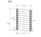
- FIG. 2 is a diagram corresponding to a cross section including the central axis A in FIG. 1 (a cross section taken along line II-II in FIG. 1).
- FIG. 3 is a schematic cross-sectional view showing the structure of the core wire portion and the insulating film that constitute the stator core.
- FIG. 4 is a flowchart showing an outline of a method for manufacturing a stator core.
- FIG. 5A is an enlarged cross-sectional view of a portion of a stator core in a first modified example.
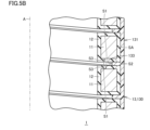
- FIG. 5B is an enlarged cross-sectional view of a portion of a stator core in a further modified example of the first modified example.
- FIG. 5A is an enlarged cross-sectional view of a portion of a stator core in a first modified example.
- FIG. 5B is an enlarged cross-sectional view of a portion of a stator core in
- FIG. 5C is an enlarged cross-sectional view of a portion of a stator core in a second modified example.
- FIG. 5D is an enlarged cross-sectional view of a portion of a stator core in a third modified example.
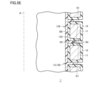
- FIG. 5E is an enlarged cross-sectional view of a portion of a stator core in a further modified example of the third modified example.
- FIG. 5F is an enlarged cross-sectional view of a portion of a stator core in the fourth modified example.
- FIG. 5G is an enlarged cross-sectional view of a portion of a stator core in the fifth modified example.
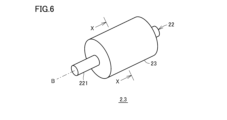
- FIG. 6 is a perspective view of the electric motor and the generator in this embodiment.
- FIG. 7 is a cross-sectional view taken along line XX in FIG.
- FIG. 8 is a diagram showing the relationship between the half-width of the peak corresponding to the iron (220) plane and the maximum magnetic permeability.
- the spiral stator core disclosed in the above-mentioned Patent Document 1 improves the problems of yield and difficulty in manufacturing.
- such a stator core has a problem that the maximum magnetic permeability, which is an important characteristic of the stator core, is insufficient.
- one of the objects of the present disclosure is to provide a stator core that can improve yield reduction and manufacturing difficulty while achieving high maximum magnetic permeability.
- the above stator core can provide a stator core that can reduce yield loss and manufacturing difficulties while achieving a high maximum magnetic permeability.
- a core wire having a spiral shape with a constant distance from a central axis the core wire being made of soft magnetic iron or silicon steel wire, and an insulating film covering the outer circumferential surface of the core wire.
- the half-width of the peak corresponding to the iron (220) plane in an X-ray diffraction analysis of the core wire is 0.31 degrees or less.
- the present inventors have studied the cause of the insufficient improvement in maximum magnetic permeability in a spiral stator core having an insulating film. As a result, they have obtained the following findings and have come up with the configuration of the stator core disclosed herein.
- a raw wire material made of soft iron or silicon steel is first prepared, and then a forming process is performed on this raw wire material to obtain a wire having a desired cross-sectional area and cross-sectional shape. At this time, since the amount of processing in the forming process is large, a large strain is introduced into the wire.
- the wire In order to remove this strain, an annealing process is performed on the wire, and after the strain is reduced, the wire is processed (coiled) into a spiral shape.
- the maximum magnetic permeability is not sufficiently improved in a stator core including a core portion manufactured in this manner.
- the present inventors have found that the maximum magnetic permeability is significantly improved by performing an annealing process after coiling. This is thought to be because coiling involves a smaller amount of processing than molding, and therefore the strain introduced is also small, but this small strain prevents the improvement of the maximum magnetic permeability.
- the inventors have discovered that a significant improvement in maximum magnetic permeability can be achieved by reducing the strain after coiling to an extremely low level, specifically to a level where the half-width of the peak corresponding to the iron (220) plane in X-ray diffraction analysis is 0.31 degrees or less. Note that small strain in the iron (220) plane (half-width of 0.31 degrees or less) means that the strain in the iron crystal lattice, including other crystal planes, is small overall.
- the half-width of the peak corresponding to the iron (220) plane in the X-ray diffraction analysis of the core wire portion is set to 0.31 degrees or less, thereby making it possible to achieve a high maximum magnetic permeability.
- the reduction in yield and the difficulty of manufacturing are improved. In this way, according to the stator core of the present disclosure, the reduction in yield and the difficulty of manufacturing are improved, and a high maximum magnetic permeability can be achieved.
- the half-width of the peak corresponding to the iron (220) plane in an X-ray diffraction analysis of the core wire portion may be 0.30 degrees or less. This configuration makes it possible to more reliably achieve a high maximum magnetic permeability.
- the insulating films covering adjacent core wire portions in a direction parallel to the central axis may be in contact with each other. This configuration can achieve a further improvement in maximum magnetic permeability.
- the stator core may further include a resin portion covering the insulating film, and in a cross section including the central axis, the resin portion may include at least one selected from the group consisting of a first portion covering the insulating film located on the opposite side of the central axis as viewed from the core portion, a second portion covering the insulating film located between the core portion and the central axis, and a third portion located between the insulating films covering adjacent core portions in a direction parallel to the central axis. This configuration can improve the insulation of the core portion.
- the resin portion may be a hardened body that bonds the insulating film that covers the core wire portions adjacent to each other in a direction parallel to the central axis. This configuration can increase the stability of the shape of the insulating-coated iron wire including the first portion, the second portion, and the insulating film.
- the cross section perpendicular to the longitudinal direction of the core wire portion may be rectangular. With this configuration, the space between adjacent core wire portions in the direction parallel to the central axis is reduced. As a result, a further improvement in maximum magnetic permeability can be achieved.
- the height of the cross section perpendicular to the longitudinal direction of the core wire portion in a direction parallel to the central axis may be 0.6 mm or less.
- the insulating film may be made of an inorganic material. Inorganic materials are suitable as materials for the insulating film that covers the core wire portion.
- the inorganic material may be a phosphate.
- Phosphate is particularly suitable as a material for the insulating film that covers the core wire from the standpoint of insulating properties, cost, ease of forming the insulating film, etc.
- the thickness of the insulating film may be 0.1 ⁇ m or more and 30 ⁇ m or less. If the thickness of the insulating film is less than 0.1 ⁇ m, there is a risk of insufficient insulation between adjacent core wire portions in a direction parallel to the central axis. On the other hand, if the thickness of the insulating film exceeds 30 ⁇ m, there is a risk of insufficient maximum magnetic permeability. Therefore, it is preferable that the thickness of the insulating film is within the above range. From the viewpoint of ensuring a higher maximum magnetic permeability, it is more preferable that the thickness of the insulating film is 5 ⁇ m or less.
- the aspect ratio which is the ratio of the length of the stator core in a direction parallel to the central axis to the outer diameter of the stator core, may be 3 or more.
- the electric motor of the present disclosure includes any one of the stator cores (1) to (11) above.
- This electric motor includes a stator core with a high maximum magnetic permeability, and therefore has high motor torque.
- the generator of the present disclosure includes any one of the stator cores described above in (1) to (11). This generator includes a stator core with a high maximum magnetic permeability, and therefore has high power generation efficiency.
- FIG. 1 is a schematic perspective view showing the structure of the stator core in this embodiment.
- FIG. 2 is a view corresponding to a cross section including the central axis A in FIG. 1 (a cross section taken along line II-II in FIG. 1).
- FIG. 3 is a schematic cross section showing the structure of the core wire portion and insulating film that make up the stator core.
- the stator core 1 in this embodiment has a structure in which an insulating coated iron wire 10 is wound in a spiral shape with a constant distance from a central axis A.
- the stator core 1 has a core wire portion 11 and an insulating film 12.
- the core wire portion 11 and the insulating film 12 constitute the insulating coated iron wire 10.
- the core wire portion 11 has a spiral shape with a constant distance r from the central axis A.
- the core wire portion 11 is composed of a wire made of electromagnetic soft iron or silicon steel.
- electromagnetic soft iron refers to electromagnetic soft iron as defined in JIS standard C2504.
- silicon steel is steel containing 1.0 mass% to 5.0 mass% silicon, 0.1 mass% or less carbon, and the remainder being iron and unavoidable impurities. Silicon steel may further contain at least one of 0.01 mass% to 1.2 mass% manganese and 0.01 mass% to 1.2 mass% aluminum.
- the shape of the cross section perpendicular to the longitudinal direction of the core wire portion 11 is not particularly limited, but may be rectangular, for example, as in this embodiment. In this disclosure, a rectangle includes a square.
- the state in which the cross-sectional shape of the core wire portion 11 is rectangular does not necessarily mean that the outer peripheral surfaces are strictly perpendicular to each other at each vertex. For example, chamfered portions may be formed in the areas of the outer peripheral surface corresponding to each vertex.
- the area of the outer peripheral surface corresponding to each vertex may be formed with a curved surface portion having an arc shape.
- the state in which the cross-sectional shape of the core wire portion 11 is rectangular means that (1) the proportion of the chamfered portions and curved surface portions formed at the corners of each side is 20% or less (preferably small), (2) the angle between the opposing sides is 2° or less (preferably 0.3° or less), and (3) the length of the other side opposite one side is 60% to 140% of the length of the other side (preferably close to 100%).
- the height h of the core wire portion 11 in a direction parallel to the central axis A of a cross section perpendicular to the longitudinal direction is preferably 0.6 mm or less.
- the width w of the core wire portion 11 in a direction perpendicular to the longitudinal direction of the cross section perpendicular to the central axis A can be appropriately determined according to the characteristics required of the stator core 1.
- the width w may be greater or smaller than the height h.
- the width w may be the same as the height h.
- the cross section perpendicular to the longitudinal direction of the core wire portion 11 may be square.
- the insulating film 12 is arranged so as to cover the outer peripheral surface of the core wire portion 11.
- the insulating film 12 may cover the end surface as well as the outer peripheral surface of the core wire portion 11.
- the material constituting the insulating film 12 is not particularly limited as long as it has insulating properties, but may be, for example, an inorganic material. From the viewpoints of insulating properties, cost, ease of insulating film formation, etc., the material constituting the insulating film 12 is preferably a phosphate.
- the phosphate is at least one selected from the group consisting of iron phosphate, zinc phosphate, and manganese phosphate.
- the material constituting the insulating film 12 may be an oxide of the soft electromagnetic iron or silicon steel constituting the core wire portion 11. In other words, the insulating film 12 may be an oxide film.
- the insulating films 12 covering adjacent core wire portions 11 in a direction parallel to the central axis A are in contact with each other.
- the outer circumferential surfaces of adjacent iron wires 10 with insulating coating are in contact with each other. Even if the insulating films 12 covering adjacent core wire portions 11 in a direction parallel to the central axis A are separated from each other in a cross section including the central axis A, the stator core 1 still functions. However, by bringing the insulating films 12 covering the core wire portions 11 into contact with each other, the maximum magnetic permeability of the stator core 1 can be improved.
- the thickness t of the insulating film 12 can be set appropriately depending on the characteristics required of the stator core 1. However, from the viewpoint of ensuring sufficient insulation while also achieving a high maximum magnetic permeability, it is preferable to set the thickness to 0.1 ⁇ m or more and 30 ⁇ m or less, and more preferably 0.1 ⁇ m or more and 5 ⁇ m or less.
- the stator core 1 of this embodiment has a spiral shape and adopts a structure including a core portion 11 made of a wire made of electromagnetic soft iron or silicon steel, and an insulating film 12 covering the outer surface of the core portion 11, thereby providing a stator core in which the reduction in yield and the difficulty of manufacturing are improved.
- the length L of the stator core 1 in the direction parallel to the central axis A is 50 mm or more, further 100 mm or more, and further 130 mm or more. If the length L of the stator core 1 in the direction parallel to the central axis A is within the above-mentioned range, the torque of the electric motor 2 (see FIG. 7, described later) including the stator core 1 can be increased. There is no upper limit to the length L of the stator core 1 in the direction parallel to the central axis A.
- the length L of the stator core 1 in the direction parallel to the central axis A is the average ((L1+L2)/2) of the lengths L1 and L2 at two points 180 degrees apart in the circumferential direction around the central axis A.
- the outer diameter D of the stator core 1 is 30 mm or less, further 20 mm or less. If the outer diameter D of the stator core 1 is within the above-mentioned range, the electric motor 2 or generator 3 including the stator core 1 can be made smaller.
- the aspect ratio (L/D) which is the ratio of the length L of the stator core 1 in the direction parallel to the central axis A to the outer diameter D of the stator core 1, is 3 or more, or 5 or more, or 10 or more, or even 15 or more. If the aspect ratio is within the above range, the electric motor 2 equipped with the stator core 1 can be made both high torque and compact. There is no upper limit to the aspect ratio.
- the stator core 1 of this embodiment the half-width of the peak corresponding to the iron (220) plane in the X-ray diffraction analysis of the core wire portion 11 is 0.31 degrees or less. In this way, the distortion of the core wire portion 11 is reduced to an extremely low level, and the stator core 1 is a stator core with improved maximum magnetic permeability. From the viewpoint of further improving the maximum magnetic permeability, it is preferable that the half-width of the peak corresponding to the iron (220) plane in the X-ray diffraction analysis of the core wire portion 11 is 0.30 degrees or less. As described above, the stator core 1 of the present disclosure is a stator core that is capable of improving yield reduction and manufacturing difficulty while achieving a high maximum magnetic permeability.
- FIG. 4 is a flow chart showing an outline of the method for manufacturing the stator core 1 in this embodiment.
- a raw wire preparation step is carried out as step S10.
- step S10 raw wire made of soft magnetic iron or silicon steel to become the core wire portion 11 is prepared.
- the wire diameter of the raw wire can be appropriately selected taking into consideration the cross-sectional area of the desired core wire portion 11 in a cross section perpendicular to the longitudinal direction, etc.
- a forming process is performed as step S20.
- the raw wire prepared in step S10 is subjected to forming processing.
- the forming process is not limited. Examples of forming processes include wire drawing and rolling. Wire drawing and rolling may be performed alone or in combination. For example, wire drawing is performed by passing the raw wire through a through hole formed in a die. Wire drawing may be performed multiple times using multiple dies. In this embodiment, the cross-sectional shape in the longitudinal direction of the core wire portion 11 is rectangular.
- a raw wire having a circular cross section perpendicular to the longitudinal direction is prepared, and by one or multiple wire drawing processes, it is processed into a wire having a circular cross section whose cross-sectional area perpendicular to the longitudinal direction is smaller than that of the raw wire.
- wire drawing is performed using a die formed with a through hole having a rectangular cross section (irregular shape processing), and a wire having a rectangular cross section perpendicular to the longitudinal direction is obtained.
- This wire becomes the core wire portion 11.
- the rolling process is performed by passing the raw wire material through rollers.
- the reduction in area in the above forming process can be, for example, 20% or more and 95% or less.
- magnetic annealing may be performed after the forming process.
- an insulating film forming process is carried out as step S30.
- an insulating film 12 is formed on the outer peripheral surface of the wire obtained in step S20, the cross section of which perpendicular to the longitudinal direction is rectangular.
- the material constituting the insulating film 12 is phosphate
- a phosphate coating process is carried out in step S30.
- the material constituting the insulating film 12 is oxide
- the core wire portion 11 after step S20 is left in the air at room temperature (25°C).
- the insulating film 12 may be an oxide film that is formed naturally (unintentionally) immediately after step S20.
- the insulating film 12 is formed on the outer peripheral surface of the electromagnetic soft iron or silicon steel wire obtained in step S20.
- a phosphate coating or an oxide film can be adopted as the insulating film forming the insulating film 12.
- the electromagnetic soft iron or silicon steel wire obtained in step S20 becomes the core wire portion 11.
- an iron wire 10 with an insulating coating including the core wire portion 11 and the insulating film 12 is obtained.
- step S40 a coiling process is carried out as step S40.
- the iron wire 10 with the insulating coating obtained in step S30 is processed into a spiral (coil) shape (coiling process).
- the coiling process can be carried out, for example, by bending the iron wire 10 with the insulating coating using a pin (processing using a coiling machine) or by winding the iron wire 10 with the insulating coating around a shaft.
- an annealing process is performed as step S50.
- an annealing process is performed on the iron wire 10 with insulating coating processed into a spiral shape.
- the annealing process can be performed, for example, by heating the iron wire 10 with insulating coating processed into a spiral shape to a temperature range of 600°C to 900°C in an inert gas atmosphere such as a nitrogen atmosphere. From the viewpoint of stability of characteristics, it is preferable to hold the iron wire 10 in the temperature range for 5 minutes to 60 minutes.
- the time to hold the iron wire 1 in the temperature range may be less than 5 minutes, but since the characteristics of the stator core 1 tend to become unstable, it is preferable to hold the iron wire 1 in the temperature range for 5 minutes or more.
- the time to hold the iron wire 1 in the temperature range may exceed 60 minutes, but from the viewpoint of productivity, it is preferable to hold the iron wire 1 in the temperature range for 60 minutes or less.
- the stator core 1 of the present embodiment can be manufactured by the above procedure.
- stator core 1 of this embodiment In the manufacturing method of the stator core 1 of this embodiment, an annealing process is performed after the coiling process is completed. As a result, the distortion of the core wire portion 11 constituting the stator core 1 is reduced to a level where the half-width of the peak corresponding to the iron (220) plane in the X-ray diffraction analysis is 0.31 degrees or less. As a result, according to the manufacturing method of the stator core of this embodiment, a stator core 1 having a high maximum magnetic permeability can be manufactured.
- the stator core 1 is heated to the above temperature range in an inert gas atmosphere in a state in which it is not constrained by other members, such as being wound around a core material, but has a free shape, and is held for the above preferred time to perform the annealing process.
- the stator core 1 of this embodiment has uniform distortion throughout the entire area and the variation in the size of the crystal grains is reduced.
- the stator core 1 includes a resin portion 13 in addition to the core portion 11 and the insulating film 12.
- the resin portion 13 covers the insulating film 12 that covers the core portion 11.
- FIG. 5A is an enlarged cross-sectional view of a portion of the stator core according to the first modification.
- the resin portion 13 includes a first portion 131 and a third portion 133.
- the first portion 131 is located on the opposite side of the central axis A as viewed from the core portion 11. In a cross section including the central axis A, the first portion 131 is located on the surface of the insulating film 12 that contacts the outer surface SA.
- the outer surface SA is the surface of the core portion 11 that is located on the opposite side of the central axis A.
- the first portion 131 has a cylindrical shape that extends along a direction parallel to the central axis A.
- the third portion 133 is continuous with the first portion 131. In a cross section including the central axis A, the third portion 133 is located between the insulating films 12 that cover the adjacent core portions 11 in a direction parallel to the central axis A. In a cross section including the central axis A, the third portion 133 is located between the insulating films 12 that contact each of the two opposing surfaces S1. In a cross section including the central axis A, the two opposing surfaces S1 are two surfaces where the adjacent core portions 11 in a direction parallel to the central axis A face each other. The third portion 133 is filled between the insulating films 12 that contact each of the two opposing surfaces S1. In a cross section including the central axis A, the third portion 133 faces the entire area of the opposing surface S1 in the radial direction.
- the resin portion 13 is composed of a hardened body 130.
- the hardened body 130 bonds the insulating films 12 that cover the core wire portions 11 that are adjacent to each other in a direction parallel to the central axis A.
- the hardened body 130 is a hardened adhesive or a hardened paint, specifically, a hardened epoxy resin adhesive or a hardened epoxy resin paint.
- the thickness (length in the radial direction) of the first portion 131 is 10 ⁇ m to 40 ⁇ m.
- the thickness (length in the direction parallel to the central axis A) of the third portion 133 is 10 ⁇ m to 40 ⁇ m.
- the resin portion 13 is formed between step S40 and step S50. After step S40, adhesive or paint is applied to the insulating coated iron wire 10 that has been processed into a spiral shape, and then the adhesive or paint is cured to form the cured body 130.
- FIG. 5B is an enlarged cross-sectional view of a portion of the stator core according to the further modified example of the first modified example.
- the third portion 133 faces a radial portion of each of the two opposing surfaces S1 in a cross section including the central axis A.
- the opposing surface S1 includes a first end S2 and a second end S3.
- the first end S2 is the end of the opposing surface S1 that is far from the central axis A.
- the second end S3 is the end of the opposing surface S1 that is closer to the central axis A.
- the third portion 133 faces the first end S2.
- the third portion 133 is offset from the second end S3.
- FIG. 5C is an enlarged cross-sectional view of a portion of the stator core in the second modified example.
- the resin part 13 includes a first part 131 (see Fig. 5A).
- the resin part 13 does not include a second part 132 (described later, see Fig. 5D) and a third part 133 (see Fig. 5A).
- FIG. 5D is an enlarged cross-sectional view of a portion of the stator core in the third modified example.
- the resin portion 13 includes a second portion 132.
- the second portion 132 is located between the core portion 11 and the central axis A.
- the second portion 132 is located on a surface of the insulating film 12 that contacts the inner side surface SB.
- the inner side surface SB is a surface of the core portion 11 that faces the central axis A.
- the second portion 132 has a cylindrical shape that extends along a direction parallel to the central axis A.
- the thickness (length in the radial direction) of the second portion 132 is 10 ⁇ m to 40 ⁇ m.
- the resin portion 13 does not include the first portion 131 (see FIG. 5A) and the third portion 133 (see FIG. 5A).
- FIG. 5E is an enlarged cross-sectional view of a portion of a stator core according to the further modified example of the third modified example.
- the resin part 13 includes a third part 133 in addition to the second part 132.
- the third part 133 is continuous with the second part 132.
- the third part 133 faces the second end part S3.
- the third part 133 is offset from the first end part S2.
- FIG. 5F is an enlarged cross-sectional view of a portion of the stator core in the fourth modified example.
- the resin part 13 includes a third part 133 (see Fig. 5A).
- the resin part 13 does not include a first part 131 (see Fig. 5A) and a second part 132 (see Fig. 5E).
- Fig. 5G is an enlarged cross-sectional view of a portion of the stator core in the fifth modified example.
- the resin part 13 includes a first part 131, a second part 132, and a third part 133.
- the third part 133 is continuous with each of the first part 131 and the second part 132.
- the resin part 13 may include at least one selected from the group consisting of the first part 131, the second part 132, and the third part 133.
- Fig. 6 is a perspective view of the electric motor and generator in this embodiment.
- Fig. 7 is a cross-sectional view taken along line XX in Fig. 1.
- the electric motor 2 includes a case 21, a shaft 22, a rotor 23, a stator core 1, and a coil 24.
- the case 21 has a cylindrical shape with an axis B.
- the case 21 houses a part of the shaft 22, the rotor 23, the stator core 1, and the coil 24.
- the shaft 22 has a common axis B with the case 21.
- the shaft 22 rotates about the axis B relative to the case 21.
- An end 221 of the shaft 22 in a direction parallel to the axis B is located outside the case 21.
- the rotor 23 is fixed to a part of the shaft 22.
- the rotor 23 has a common axis B with the shaft 22.
- the rotor 23 rotates about the axis B together with the shaft 22.
- the rotor 23 is composed of a permanent magnet.
- the stator core 1 is fixed to the inner surface of the case 21.
- the stator core 1 is located radially outside the rotor 23.
- the stator core 1 is located away from the outer circumferential surface of the rotor 23.
- the rotor 23 rotates relative to the stator core 1.
- the central axis A of the stator core 1 coincides with the axis B of the rotor 23.
- the coil 24 is located between the rotor 23 and the stator core 1.
- the coil 24 is located away from the outer circumferential surface of the rotor 23.
- the coil 24 is fixed to the inner surface 111 of the stator core 1.
- the generator 3 has the same configuration as the electric motor 2. That is, the generator 3 has a case 21, a shaft 22, a rotor 23, a stator core 1, and a coil 24.
- the stator core disclosed herein was fabricated, and an experiment was conducted to confirm that a high maximum magnetic permeability could be obtained.
- the experimental procedure was as follows.
- a stator core was produced using the same procedure as in the above embodiment, including steps S10 to S50 (Process A). Meanwhile, for comparison, a stator core was produced using the above embodiment's stator core manufacturing method, but with steps S40 and S50 swapped (Process B).
- the width w of the core was 1.0 mm
- the height h was 1.7 mm
- the thickness t of the insulating layer was 1 to 3 ⁇ m
- the outer diameter D of the stator core was 19.6 mm
- the inner diameter was 17.6 mm.
- the annealing temperature was changed in the temperature range of 400°C to 800°C, and samples were produced in which the magnitude of strain in the core (half-width of the peak corresponding to the iron (220) plane in X-ray diffraction analysis) was changed.
- X-ray diffraction analysis was performed on the core of the obtained sample to measure the half-width of the peak corresponding to the iron (220) plane.
- the magnetization curves of the obtained samples were also investigated, and the maximum magnetic permeability was calculated from the obtained magnetization curves.
- the magnetization curves were investigated using the secondary winding method, with 108 turns of primary winding and 30 turns of secondary winding wound around the ring. Iron loss was measured at room temperature (25°C) using an AC BH analyzer (manufactured by Metron Giken Co., Ltd.) until an excitation magnetic flux density Bm of 2.2 T (22 kG) was reached.
- Figure 8 shows the relationship between the half-width and maximum magnetic permeability of the samples obtained as a result of the above experiment.
- the horizontal axis corresponds to the half-width of the peak corresponding to the iron (220) plane in the X-ray diffraction analysis of the core wire.
- the vertical axis corresponds to the maximum magnetic permeability of the sample.
- the maximum magnetic permeability is displayed as relative magnetic permeability (unitless).
- the measurement points corresponding to the samples of process A and process B are located on a common curve. It can also be seen that the maximum permeability increases sharply in the region where the half-width of the peak corresponding to the iron (220) plane is 0.31 degrees or less, and further in the region where it is 0.30 degrees or less, and an excellent maximum permeability can be obtained. From the above experimental results, it is confirmed that the stator core disclosed herein can improve yield reduction and manufacturing difficulties while achieving a high maximum permeability.
- the measurement points of process B with the smaller half-width correspond to the sample with the heating temperature during annealing of 700°C.
- the measurement points of process A with the heating temperatures during annealing of 600°C, 700°C, and 800°C correspond to the three measurement points with half-widths of less than 0.30 degrees. From this, it is considered that in process B, a sufficiently small amount of strain was achieved during annealing with a half-width of less than 0.30 degrees, but strain was introduced by the subsequent coiling process, exceeding the strain that can achieve a high maximum magnetic permeability.
- stator core 1 stator core, 2 motor, 3 generator, 10 iron wire with insulating coating, 11 core wire, 12 insulating film, 13 resin part, 21 case, 22 shaft, 23 rotor, 24 coil, 111 inner surface, 130 hardened body, 131 first part, 132 second part, 133 third part, 221 end, A central axis, B axis, L length parallel to the central axis of the stator core, L1, L2 lengths at two points 180 degrees apart in the circumferential direction around the central axis, D outer diameter, S1 opposing surface, S2 first end, S3 second end, SA outer surface, SB inner surface, h height, r distance, t thickness, w width.
Landscapes
- Engineering & Computer Science (AREA)
- Power Engineering (AREA)
- Iron Core Of Rotating Electric Machines (AREA)
Priority Applications (2)
| Application Number | Priority Date | Filing Date | Title |
|---|---|---|---|
| JP2025523013A JPWO2025110247A1 (https=) | 2023-11-24 | 2024-11-22 | |
| CN202480057334.4A CN121794870A (zh) | 2023-11-24 | 2024-11-22 | 定子芯、电动机以及发电机 |
Applications Claiming Priority (2)
| Application Number | Priority Date | Filing Date | Title |
|---|---|---|---|
| JP2023199294 | 2023-11-24 | ||
| JP2023-199294 | 2023-11-24 |
Publications (1)
| Publication Number | Publication Date |
|---|---|
| WO2025110247A1 true WO2025110247A1 (ja) | 2025-05-30 |
Family
ID=95826759
Family Applications (2)
| Application Number | Title | Priority Date | Filing Date |
|---|---|---|---|
| PCT/JP2024/041537 Pending WO2025110247A1 (ja) | 2023-11-24 | 2024-11-22 | ステータコア、電動機および発電機 |
| PCT/JP2024/041538 Pending WO2025110248A1 (ja) | 2023-11-24 | 2024-11-22 | ステータコア、電動機および発電機 |
Family Applications After (1)
| Application Number | Title | Priority Date | Filing Date |
|---|---|---|---|
| PCT/JP2024/041538 Pending WO2025110248A1 (ja) | 2023-11-24 | 2024-11-22 | ステータコア、電動機および発電機 |
Country Status (3)
| Country | Link |
|---|---|
| JP (2) | JPWO2025110248A1 (https=) |
| CN (2) | CN121794870A (https=) |
| WO (2) | WO2025110247A1 (https=) |
Citations (6)
| Publication number | Priority date | Publication date | Assignee | Title |
|---|---|---|---|---|
| JPS61214746A (ja) * | 1985-03-15 | 1986-09-24 | Toshiba Corp | 電気機器鉄心の焼鈍方法 |
| JP2003189509A (ja) * | 2001-12-21 | 2003-07-04 | Matsushita Electric Ind Co Ltd | コアレスモータ |
| JP2012031458A (ja) * | 2010-07-29 | 2012-02-16 | Jfe Steel Corp | 成形性に優れた高強度冷延薄鋼板およびその製造方法 |
| JP2013102587A (ja) * | 2011-11-08 | 2013-05-23 | Seiko Epson Corp | バックヨークの製造方法、電動機、ロボット |
| WO2020129921A1 (ja) * | 2018-12-17 | 2020-06-25 | 日本製鉄株式会社 | ステータ用接着積層コアおよび回転電機 |
| WO2020149405A1 (ja) * | 2019-01-17 | 2020-07-23 | 日本製鉄株式会社 | 無方向性電磁鋼板、分割型固定子および回転電機 |
Family Cites Families (4)
| Publication number | Priority date | Publication date | Assignee | Title |
|---|---|---|---|---|
| JPH05219665A (ja) * | 1992-02-03 | 1993-08-27 | Matsushita Electric Ind Co Ltd | 円筒状ブラシレスモータ |
| JPH08223831A (ja) * | 1995-02-10 | 1996-08-30 | Toshiba Corp | 回転電機用の鉄心および回転子鉄心 |
| JP2004032861A (ja) * | 2002-06-24 | 2004-01-29 | Nidec Copal Corp | ステッピングモータ |
| JP2022131772A (ja) * | 2021-02-26 | 2022-09-07 | 日本電産株式会社 | モータ |
-
2024
- 2024-11-22 WO PCT/JP2024/041537 patent/WO2025110247A1/ja active Pending
- 2024-11-22 JP JP2025524489A patent/JPWO2025110248A1/ja active Pending
- 2024-11-22 CN CN202480057334.4A patent/CN121794870A/zh active Pending
- 2024-11-22 CN CN202480058360.9A patent/CN121866699A/zh active Pending
- 2024-11-22 WO PCT/JP2024/041538 patent/WO2025110248A1/ja active Pending
- 2024-11-22 JP JP2025523013A patent/JPWO2025110247A1/ja active Pending
Patent Citations (6)
| Publication number | Priority date | Publication date | Assignee | Title |
|---|---|---|---|---|
| JPS61214746A (ja) * | 1985-03-15 | 1986-09-24 | Toshiba Corp | 電気機器鉄心の焼鈍方法 |
| JP2003189509A (ja) * | 2001-12-21 | 2003-07-04 | Matsushita Electric Ind Co Ltd | コアレスモータ |
| JP2012031458A (ja) * | 2010-07-29 | 2012-02-16 | Jfe Steel Corp | 成形性に優れた高強度冷延薄鋼板およびその製造方法 |
| JP2013102587A (ja) * | 2011-11-08 | 2013-05-23 | Seiko Epson Corp | バックヨークの製造方法、電動機、ロボット |
| WO2020129921A1 (ja) * | 2018-12-17 | 2020-06-25 | 日本製鉄株式会社 | ステータ用接着積層コアおよび回転電機 |
| WO2020149405A1 (ja) * | 2019-01-17 | 2020-07-23 | 日本製鉄株式会社 | 無方向性電磁鋼板、分割型固定子および回転電機 |
Also Published As
| Publication number | Publication date |
|---|---|
| CN121866699A (zh) | 2026-04-14 |
| CN121794870A (zh) | 2026-04-03 |
| WO2025110248A1 (ja) | 2025-05-30 |
| JPWO2025110247A1 (https=) | 2025-05-30 |
| JPWO2025110248A1 (https=) | 2025-05-30 |
Similar Documents
| Publication | Publication Date | Title |
|---|---|---|
| JP5227756B2 (ja) | 軟磁性材料の製造方法 | |
| CN101277050A (zh) | 感应电机 | |
| JP2002530042A (ja) | 電動モータ用のバルクアモルファス金属磁気構成要素 | |
| EP1088382A1 (en) | Amorphous metal stator for a radial-flux electric motor | |
| CN1992468A (zh) | 电动机 | |
| CN102545415A (zh) | 一种非晶态合金径向磁场电机 | |
| US20080100154A1 (en) | Compacted magnetic core with high resistance, manufacturing method thereof, and motor for electric car | |
| CN109980863A (zh) | 定子的制造方法 | |
| WO2025110247A1 (ja) | ステータコア、電動機および発電機 | |
| JP5373002B2 (ja) | 希土類磁石及びそれを用いた回転機 | |
| CN112421897A (zh) | 一种无轭分块电枢轴向磁通电机定子铁心的制造方法 | |
| JP2023107731A (ja) | 軟磁気特性および加工性に優れたFe系非晶質合金、軟磁気特性および加工性に優れたFe系非晶質合金薄帯、巻鉄心、積鉄心および回転電機 | |
| US7843092B2 (en) | Core and method for producing core | |
| JP2006006015A (ja) | ステータコア | |
| JP2009114511A (ja) | 軟磁性金属箔の製造方法 | |
| JP2001303213A (ja) | 高効率モータ用の無方向性電磁鋼板 | |
| KR20260061252A (ko) | 스테이터 코어, 전동기 및 발전기 | |
| JP2021019385A (ja) | 回転機コア及びその製造方法 | |
| KR100937843B1 (ko) | 실린더형 비정질 합금 백 요크의 제조방법 및 이를 이용한 슬롯레스 모터의 제조방법 | |
| Takizawa et al. | Development of transverse flux motor with improved material and manufacturing method | |
| JP2010034335A (ja) | 希土類磁石及びそれを用いた回転機 | |
| JP7492105B2 (ja) | 積層コアおよび電気機器 | |
| JP2008259371A (ja) | 回転電機 | |
| JP5130131B2 (ja) | 配向圧粉磁心 | |
| TWI909363B (zh) | 積層鐵芯、旋轉電機及積層鐵芯之製造方法 |
Legal Events
| Date | Code | Title | Description |
|---|---|---|---|
| ENP | Entry into the national phase |
Ref document number: 2025523013 Country of ref document: JP Kind code of ref document: A |
|
| WWE | Wipo information: entry into national phase |
Ref document number: 2025523013 Country of ref document: JP |
|
| 121 | Ep: the epo has been informed by wipo that ep was designated in this application |
Ref document number: 24894237 Country of ref document: EP Kind code of ref document: A1 |