WO2025089134A1 - プラズマエッチング装置及びプラズマエッチング方法 - Google Patents
プラズマエッチング装置及びプラズマエッチング方法 Download PDFInfo
- Publication number
- WO2025089134A1 WO2025089134A1 PCT/JP2024/036692 JP2024036692W WO2025089134A1 WO 2025089134 A1 WO2025089134 A1 WO 2025089134A1 JP 2024036692 W JP2024036692 W JP 2024036692W WO 2025089134 A1 WO2025089134 A1 WO 2025089134A1
- Authority
- WO
- WIPO (PCT)
- Prior art keywords
- gas
- chamber
- flow rate
- diffusion chamber
- plasma
- Prior art date
- Legal status (The legal status is an assumption and is not a legal conclusion. Google has not performed a legal analysis and makes no representation as to the accuracy of the status listed.)
- Pending
Links
Images


Classifications
-
- H—ELECTRICITY
- H01—ELECTRIC ELEMENTS
- H01J—ELECTRIC DISCHARGE TUBES OR DISCHARGE LAMPS
- H01J37/00—Discharge tubes with provision for introducing objects or material to be exposed to the discharge, e.g. for the purpose of examination or processing thereof
- H01J37/32—Gas-filled discharge tubes
- H01J37/32431—Constructional details of the reactor
- H01J37/3244—Gas supply means
- H01J37/32449—Gas control, e.g. control of the gas flow
-
- H—ELECTRICITY
- H01—ELECTRIC ELEMENTS
- H01J—ELECTRIC DISCHARGE TUBES OR DISCHARGE LAMPS
- H01J37/00—Discharge tubes with provision for introducing objects or material to be exposed to the discharge, e.g. for the purpose of examination or processing thereof
- H01J37/32—Gas-filled discharge tubes
- H01J37/32431—Constructional details of the reactor
- H01J37/3244—Gas supply means
-
- H—ELECTRICITY
- H01—ELECTRIC ELEMENTS
- H01J—ELECTRIC DISCHARGE TUBES OR DISCHARGE LAMPS
- H01J37/00—Discharge tubes with provision for introducing objects or material to be exposed to the discharge, e.g. for the purpose of examination or processing thereof
- H01J37/32—Gas-filled discharge tubes
- H01J37/32431—Constructional details of the reactor
- H01J37/32798—Further details of plasma apparatus not provided for in groups H01J37/3244 - H01J37/32788; special provisions for cleaning or maintenance of the apparatus
- H01J37/32816—Pressure
- H01J37/32834—Exhausting
-
- H—ELECTRICITY
- H10—SEMICONDUCTOR DEVICES; ELECTRIC SOLID-STATE DEVICES NOT OTHERWISE PROVIDED FOR
- H10P—GENERIC PROCESSES OR APPARATUS FOR THE MANUFACTURE OR TREATMENT OF DEVICES COVERED BY CLASS H10
- H10P50/00—Etching of wafers, substrates or parts of devices
- H10P50/20—Dry etching; Plasma etching; Reactive-ion etching
- H10P50/24—Dry etching; Plasma etching; Reactive-ion etching of semiconductor materials
- H10P50/242—Dry etching; Plasma etching; Reactive-ion etching of semiconductor materials of Group IV materials
-
- H—ELECTRICITY
- H01—ELECTRIC ELEMENTS
- H01J—ELECTRIC DISCHARGE TUBES OR DISCHARGE LAMPS
- H01J2237/00—Discharge tubes exposing object to beam, e.g. for analysis treatment, etching, imaging
- H01J2237/32—Processing objects by plasma generation
- H01J2237/33—Processing objects by plasma generation characterised by the type of processing
- H01J2237/334—Etching
- H01J2237/3343—Problems associated with etching
- H01J2237/3346—Selectivity
Definitions
- This disclosure relates to a plasma etching apparatus and a plasma etching method.
- Patent Document 1 discloses a method for selectively etching a silicon oxide film on a substrate having a silicon nitride film and a silicon oxide film on the surface thereof, in which the substrate is intermittently exposed multiple times to at least one of a processing gas containing hydrogen fluoride gas and ammonia gas, and a processing gas containing a compound containing nitrogen, hydrogen, and fluorine in a vacuum atmosphere.
- One aspect of the present disclosure is a plasma etching apparatus comprising a chamber, a gas supply unit for supplying gas to the chamber, and a control unit.
- the gas supply unit comprises a gas box for supplying the gas, a gas diffusion chamber in which the gas from the gas box is diffused and introduced into the chamber, and an exhaust unit for exhausting the gas in the gas diffusion chamber.
- the control unit executes control including the steps of (a) supplying a first gas from the gas box at a first flow rate to generate plasma in the chamber, and (b) after stopping the supply of the first gas from the gas box, supplying a second gas from the gas box at a second flow rate and exhausting the gas diffusion chamber.
- the pressure in the gas diffusion chamber is maintained at or above a threshold value determined in advance based on plasma processing conditions as a pressure for maintaining the plasma in the chamber.
- gas switching can be performed appropriately during plasma etching.
- FIG. 1 is an explanatory diagram illustrating a configuration example of a plasma etching system according to an embodiment.
- 1 is a cross-sectional view showing a configuration example of a plasma etching apparatus according to an embodiment.
- FIG. 2 is a schematic diagram showing an outline of a configuration of a gas supply unit according to the first embodiment.
- FIG. 2 is a schematic diagram illustrating an example of the configuration of an exhaust unit.
- 10A and 10B are schematic diagrams illustrating an outline of another configuration example of the exhaust unit.
- 4 is a sequence chart relating to flow rate control in a gas supply method.
- 11 is a graph showing the pressure in the gas diffusion chamber in the gas supply method.
- 13 is a sequence chart relating to a modified example of flow rate control in a gas supply method.
- FIG. 1 is an explanatory diagram illustrating a configuration example of a plasma etching system according to an embodiment.
- 1 is a cross-sectional view showing a configuration example of a plasma etching apparatus
- 11 is a schematic diagram showing an outline of a configuration of a gas supply unit according to a second embodiment.
- 4 is a sequence chart relating to flow rate control in a gas supply method.
- 11 is a graph showing the pressure in the gas diffusion space and the chamber in the gas supply method.
- 6 is a sequence chart for flow rate control in a gas supply method according to a comparative example, and a graph showing pressure values in a gas diffusion space or chamber.
- a plasma etching process is performed in which a desired process gas is supplied to a process module that contains a semiconductor wafer (hereafter referred to as "substrate"), and the substrate is etched with the plasma of the process gas.
- Substrates processed by plasma etching include those having multiple layers stacked on the surface with different etching selectivity ratios.
- a process gas with a high selectivity ratio for each layer may be supplied in sequence, and after supplying one process gas to etch one layer, another process gas may be supplied to etch another layer, and these steps may be carried out in succession.
- Patent Document 1 discloses a method for selectively etching a silicon oxide film on a substrate having a silicon nitride film and a silicon oxide film on the surface thereof, in which the substrate is intermittently exposed multiple times to at least one of a processing gas containing hydrogen fluoride gas and ammonia gas, and a processing gas containing a compound containing nitrogen, hydrogen, and fluorine in a vacuum atmosphere.
- the gas diffusion chamber when exhausting one process gas and then supplying another process gas, the gas diffusion chamber may be exhausted through the shower head by an exhaust device connected to the chamber. In such cases, the flow of the process gas through the gas inlet of the shower head may become rate-limiting, preventing rapid exhaust of the gas diffusion chamber.
- the present inventors have studied this problem extensively and have come up with the idea of providing an exhaust section capable of exhausting the inside of the gas diffusion chamber at a sufficient speed. Furthermore, the present inventors have studied this problem extensively and have found that such an exhaust section has the following problem. That is, as shown in Fig. 12 of the comparative example, when switching between gases by supplying a first gas, exhausting the first gas through the exhaust section, and then supplying a second gas, the pressure in the gas diffusion chamber decreases while the exhaust section is exhausting the inside of the gas diffusion chamber, and thus the pressure in the chamber decreases. When the pressure in the chamber decreases below a threshold pressure PCT required to maintain the plasma generation state, the plasma generation state changes and, in some cases, an extinguishment occurs.
- the technology disclosed herein appropriately switches gases during plasma etching. Specifically, after the supply of the first gas is stopped, a second gas is supplied and the gas diffusion chamber is evacuated by an exhaust section provided in the gas diffusion chamber.
- the gas supply is controlled so that the pressure in the gas diffusion chamber is equal to or greater than the threshold pressure in the diffusion chamber at which plasma can be maintained in the chamber, or the pressure in the chamber is equal to or greater than the threshold pressure in the chamber at which plasma can be maintained in the chamber.
- FIG. 1 is a diagram for explaining a configuration example of a plasma etching system.
- the plasma etching system includes a plasma etching apparatus 1 and a control unit 2.
- the plasma etching system is an example of a substrate processing system
- the plasma etching apparatus 1 is an example of a substrate processing apparatus.
- the plasma etching apparatus 1 includes a plasma etching chamber 10 (hereinafter referred to as "chamber 10"), a substrate support unit 11, and a plasma generation unit 12.
- the chamber 10 has a plasma processing space.
- the chamber 10 also has at least one gas supply port for supplying at least one processing gas to the plasma processing space, and at least one gas exhaust port for exhausting gas from the plasma processing space.
- the gas supply port is connected to a gas box 21 described later, and the gas exhaust port is connected to an exhaust system 40 described later.
- the substrate support unit 11 is disposed in the plasma processing space, and has a substrate support surface for supporting a substrate.
- the plasma generating unit 12 is configured to generate a plasma PL from at least one processing gas supplied into the plasma processing space.
- the plasma PL formed in the plasma processing space may be a capacitively coupled plasma (CCP), an inductively coupled plasma (ICP), an ECR plasma (Electron-Cyclotron-resonance plasma), a helicon wave plasma (HWP), a surface wave plasma (SWP), or the like.
- various types of plasma generating units may be used, including AC (Alternating Current) plasma generating units and DC (Direct Current) plasma generating units.
- the AC signal (AC power) used in the AC plasma generating unit has a frequency in the range of 100 kHz to 10 GHz.
- AC signals include RF (Radio Frequency) signals and microwave signals.
- the RF signal has a frequency in the range of 100 kHz to 150 MHz.
- the acquired program is stored in the storage unit 2a2 and is read from the storage unit 2a2 by the processing unit 2a1 and executed.
- the medium may be various storage media readable by the computer 2a, or may be a communication line connected to the communication interface 2a3.
- the processing unit 2a1 may be a CPU (Central Processing Unit).
- the memory unit 2a2 may include a RAM (Random Access Memory), a ROM (Read Only Memory), a HDD (Hard Disk Drive), a SSD (Solid State Drive), or a combination of these.
- the communication interface 2a3 may communicate with the plasma etching apparatus 1 via a communication line such as a LAN (Local Area Network).
- FIG. 2 is a diagram for explaining an example of the configuration of the capacitively coupled plasma etching apparatus 1.
- the plasma etching apparatus 1 includes a chamber 10, a substrate support 11, a gas supply 20, a power supply 30, and an exhaust system 40.
- the substrate support 11 is disposed in the chamber 10.
- the substrate support 11 includes a main body 111 and a ring assembly 112.
- the main body 111 has a central region 111a for supporting the substrate W and an annular region 111b for supporting the ring assembly 112.
- a wafer is an example of a substrate W.
- the annular region 111b of the main body 111 surrounds the central region 111a of the main body 111 in a plan view.
- the substrate W is disposed on the central region 111a of the main body 111
- the ring assembly 112 is disposed on the annular region 111b of the main body 111 so as to surround the substrate W on the central region 111a of the main body 111. Therefore, the central region 111a is also called a substrate support surface for supporting the substrate W, and the annular region 111b is also called a ring support surface for supporting the ring assembly 112.
- the main body 111 includes a base 1110 and an electrostatic chuck 1111.
- the base 1110 includes a conductive member.
- the conductive member of the base 1110 may function as a lower electrode.
- the electrostatic chuck 1111 is disposed on the base 1110.
- the electrostatic chuck 1111 includes a ceramic member 1111a and an electrostatic electrode 1111b disposed within the ceramic member 1111a.
- the ceramic member 1111a has a central region 111a. In one embodiment, the ceramic member 1111a also has an annular region 111b. Note that other members surrounding the electrostatic chuck 1111, such as an annular electrostatic chuck or an annular insulating member, may have the annular region 111b.
- the ring assembly 112 includes one or more annular members.
- the one or more annular members include one or more edge rings and at least one cover ring.
- the edge rings are formed of a conductive or insulating material, and the cover rings are formed of an insulating material.
- the gas supply unit 20 includes a gas box 21, a gas flow path 22, a gas inlet, and an exhaust unit 24, which will be described in detail later.
- the gas box 21 is configured to supply a plurality of gases supplied from a gas source by controlling the flow rate.
- the gas flow path 22 is configured to supply the gas supplied from the gas box 21 to the gas inlet.
- the gas inlet is configured to introduce two or more processing gases into the chamber 10.
- the exhaust unit 24 is configured to exhaust the gas introduced to the gas inlet.
- the gas inlet includes a shower head 25.
- the shower head 25 is disposed above the substrate support 11. In one embodiment, the shower head 25 constitutes at least a part of the ceiling of the chamber 10.
- the chamber 10 has a plasma processing space 10s defined by the shower head 25, the sidewall 10a of the chamber 10, and the substrate support 11.
- the chamber 10 is grounded.
- the shower head 25 and the substrate support 11 are electrically insulated from the housing of the chamber 10.
- the shower head 25 is configured to introduce the processing gas from the gas box 21 into the plasma processing space 10s.
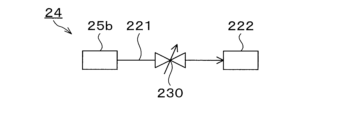
- the shower head 25 has at least one gas supply port 25a, at least one gas diffusion chamber 25b, and multiple gas inlets 25c.
- the processing gas supplied to the gas supply port 25a passes through the gas diffusion chamber 25b and is introduced into the plasma processing space 10s from the multiple gas inlets 25c.
- the shower head 25 also includes at least one upper electrode.
- the gas introduction section may include, in addition to the shower head 25, one or more side gas injectors (SGI) attached to one or more openings formed in the side wall 10a.
- SGI side gas injectors
- the gas box 21 may include at least one gas source 26 and at least one flow controller 27.
- the gas box 21 is configured to supply two or more process gases from respective gas sources 26 through respective flow controllers 27 to the showerhead 25.
- Each flow controller 27 may include, for example, a mass flow controller or a pressure-controlled flow controller.
- the gas box 21 may include at least one flow modulation device to modulate or pulse the flow rate of at least one process gas.
- the power supply 30 includes an RF power supply 31 coupled to the chamber 10 via at least one impedance matching circuit.
- the RF power supply 31 is configured to supply at least one RF signal (RF power) to at least one lower electrode and/or at least one upper electrode. This generates a plasma PL from at least one processing gas supplied to the plasma processing space 10s. Therefore, the RF power supply 31 can function as at least a part of the plasma generating unit 12.
- a bias RF signal to at least one lower electrode, a bias potential is generated on the substrate W, and ion components in the formed plasma can be attracted to the substrate W.
- the RF power supply 31 includes a first RF generating unit 31a and a second RF generating unit 31b.
- the first RF generating unit 31a is coupled to at least one lower electrode and/or at least one upper electrode via at least one impedance matching circuit and configured to generate a source RF signal (source RF power) for plasma generation.
- the source RF signal has a frequency in the range of 10 MHz to 150 MHz.
- the first RF generating unit 31a may be configured to generate multiple source RF signals having different frequencies. The generated one or more source RF signals are supplied to at least one lower electrode and/or at least one upper electrode.
- the second RF generator 31b is coupled to at least one lower electrode via at least one impedance matching circuit and configured to generate a bias RF signal (bias RF power).
- the frequency of the bias RF signal may be the same as or different from the frequency of the source RF signal.
- the bias RF signal has a lower frequency than the frequency of the source RF signal.
- the bias RF signal has a frequency in the range of 100 kHz to 60 MHz.
- the second RF generator 31b may be configured to generate multiple bias RF signals having different frequencies.
- the generated one or more bias RF signals are provided to at least one lower electrode. Also, in various embodiments, at least one of the source RF signal and the bias RF signal may be pulsed.
- the power supply 30 may also include a DC power supply 32 coupled to the chamber 10.
- the DC power supply 32 includes a first DC generator 32a and a second DC generator 32b.
- the first DC generator 32a is connected to at least one lower electrode and configured to generate a first DC signal.
- the generated first DC signal is applied to the at least one lower electrode.
- the second DC generator 32b is connected to at least one upper electrode and configured to generate a second DC signal.
- the generated second DC signal is applied to the at least one upper electrode.
- the first and second DC signals may be pulsed.
- a sequence of voltage pulses is applied to at least one lower electrode and/or at least one upper electrode.
- the voltage pulses may have a rectangular, trapezoidal, triangular or combination thereof pulse waveform.
- a waveform generator for generating a sequence of voltage pulses from the DC signal is connected between the first DC generator 32a and at least one lower electrode.
- the first DC generator 32a and the waveform generator constitute a voltage pulse generator.
- the second DC generator 32b and the waveform generator constitute a voltage pulse generator
- the voltage pulse generator is connected to at least one upper electrode.
- the voltage pulses may have a positive polarity or a negative polarity.
- the sequence of voltage pulses may also include one or more positive polarity voltage pulses and one or more negative polarity voltage pulses within one period.
- the first and second DC generating units 32a and 32b may be provided in addition to the RF power source 31, or the first DC generating unit 32a may be provided in place of the second RF generating unit 31b.
- the exhaust system 40 may be connected to, for example, a gas exhaust port 10e provided at the bottom of the chamber 10.
- the exhaust system 40 may include a pressure regulating valve and a vacuum pump.
- the pressure in the plasma processing space 10s is adjusted by the pressure regulating valve.
- the vacuum pump may include a turbomolecular pump, a dry pump, or a combination thereof.
- Fig. 3 is a schematic diagram showing an outline of the configuration of the gas supply unit 20. Note that in Fig. 3, for the sake of convenience, the chamber 10 and part of the substrate support unit 11, the plasma generation unit 12, and the like in the plasma etching apparatus 1 are omitted.
- the gas box 21 includes a first gas source 201 that supplies a first gas and a second gas source 202 that supplies a second gas.
- Each of the first gas source 201 and the second gas source 202 may include a plurality of gas sources.
- some of the gas sources may be shared by the first gas source 201 and the second gas source.
- the first gas and the second gas may be known gases that can selectively etch either a silicon nitride film or a silicon oxide film.
- the gas flow path 22 includes a first flow path 211 downstream of the first gas source 201 through which the first gas flows.
- the gas flow path 22 also includes a second flow path 212 downstream of the second gas source 202 through which the second gas flows.
- the first flow path 211 and the second flow path 212 join downstream of these flow paths to provide a common flow path 213 through which any one of the gases flows.
- the common flow path 213 according to this embodiment includes a branch structure 214 that distributes the gas so that the pressure in the surface direction is uniform.
- the common flow path 213 is connected to a plurality of gas supply ports 25a in the shower head 25 at the downstream end of the branch structure 214.
- the first flow path 211 includes a first valve 215 at the end connected to the common flow path 213.
- the second flow path 212 includes a second valve 216 at the end connected to the common flow path 213.
- the first gas supplied from the first gas source 201 flows through the first flow path 211 and into the common flow path 213.
- the first gas is dispersed as it flows through the branching structure 214 of the common flow path 213, and flows from the downstream end of the branching structure 214 into the gas diffusion chamber 25b via the multiple gas supply ports 25a in the shower head 25.
- the first gas is diffused in the gas diffusion chamber 25b so that the surface pressure distribution is approximately uniform, and then is introduced into the chamber 10 via the gas inlet port 25c.
- the gas diffusion chamber 25b is equipped with a pressure gauge P1.
- the pressure gauge P1 is configured to measure the pressure inside the gas diffusion chamber 25b and, as an example, to transmit the measurement value information to the control unit 2.
- the chamber 10 is equipped with a pressure gauge P2.
- the pressure gauge P2 is configured to measure the pressure inside the chamber 10 and, for example, to transmit the measurement value information to the control unit 2.
- the exhaust section 24 is connected to the gas diffusion chamber 25b.
- the exhaust section 24 includes an exhaust flow path 221 and a vacuum pump 222.
- the exhaust flow path 221 has an end connected to the gas diffusion chamber 25b and an end connected to the vacuum pump 222, and is configured to allow gas to flow therethrough.
- the vacuum pump 222 may include a turbomolecular pump, a dry pump, or a combination of these.
- the vacuum pump 222 may also be included in the exhaust system 40.
- multiple exhaust flow paths 221 are provided, and the ends of each that are connected to the gas diffusion chamber 25b are evenly arranged in the circumferential direction in a plan view of the gas diffusion chamber 25b. This allows the gas diffusion chamber 25b to be evacuated so that the pressure distribution in the surface direction is even.
- the exhaust unit 24 includes a control valve 230 in the exhaust flow path 221.
- the control valve 230 is configured so that the opening degree, opening/closing timing, or opening time can be controlled by the control unit 2 to adjust the flow rate of gas passing through the exhaust flow path 221.
- the exhaust section 24 includes a tank 240 in the exhaust flow path 221, and includes a first tank valve 241 and a second tank valve 242 before and after the tank 240.
- the inside of the tank 240 is configured to be able to maintain a negative pressure relative to the gas diffusion chamber 25b.
- the volume of the tank 240 is approximately the same as the volume of the gas diffusion chamber 25b.
- a gas supply method MT1 for supplying a gas to the chamber 10 using the gas supply unit 20 according to the first embodiment will be described with reference to Fig. 6 and Fig. 7.
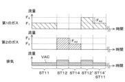
- Fig. 6 is a sequence chart for controlling the flow rate of the first gas or the second gas supplied from the first gas source 201 or the second gas source 202, and the exhaust flow rate from the gas diffusion chamber 25b by the exhaust unit 24 in the gas supply method MT1.
- Gas supply method MT1 is a method that involves switching the gas supplied to chamber 10 from a first gas to a second gas, or from the second gas to the first gas, and includes the following steps ST11 to ST14.
- step ST11 the supply of the first gas from the first gas source 201 is started at a first flow rate F 1 to generate plasma PL, and the supply of the first gas is stopped after a desired time.
- the first flow rate F 1 is a flow rate for maintaining the chamber 10 at a desired pressure in order to maintain the generation state of plasma PL of the first gas in the chamber 10.
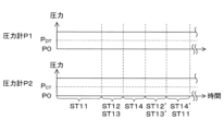
- the pressure in the gas diffusion chamber 25b is maintained at a diffusion chamber pressure threshold P DT or higher.
- step ST12 the second gas source 202 starts to supply the second gas at a second flow rate F2 .
- the second flow rate F2 will be described later.
- step ST13 the gas diffusion chamber 25b is evacuated by the exhaust unit 24 at an exhaust flow rate VAC, which will be described later. During this exhaust, the gas diffusion chamber 25b is maintained at a desired pressure as shown in FIG. 7, for reasons that will be described later. After an exhaust time, which will be described later, has elapsed, the exhaust of the gas diffusion chamber 25b is stopped.
- step ST14 the flow rate of the second gas supplied from the second gas source 202 is changed from the second flow rate F2 to a third flow rate F3 and is continued for a desired time.
- the third flow rate F3 is a flow rate smaller than the second flow rate F2 and is a flow rate for maintaining a desired pressure in the chamber 10 in order to maintain a state in which the plasma PL of the second gas is generated in the chamber 10.
- steps ST11 to ST14 complete the switch from the first gas to the second gas.
- plasma etching can be performed on the substrate W placed in the chamber 10 using the plasma PL of the first gas or the plasma PL of the second gas, respectively.
- the supply of the second gas is stopped, and then the first gas is supplied at a fourth flow rate F4 by a step ST12' similar to the step ST12, and the second gas is exhausted by a step ST13' similar to the step ST13, so that the second gas can be switched to the first gas.
- the flow rate of the first gas is changed from the fourth flow rate F4 to the first flow rate F1 by a step ST14' similar to the step ST14, and the process returns to the step ST11.
- the first flow rate F1 of the first gas corresponds to the third flow rate F3 of the second gas
- the fourth flow rate F4 of the first gas corresponds to the second flow rate F2 of the second gas. Then, the plasma etching can be continued while switching between the first gas and the second gas a desired number of times.
- step ST12 the second flow rate F2 in step ST12 will be described.
- the first gas supplied in step ST11 remains in the common flow path 213 and the gas diffusion chamber 25b when the supply is terminated.
- the second gas is sequentially filled in the common flow path 213 and the gas diffusion chamber 25b.
- the second gas pushes out the first gas remaining in the common flow path 213 in the direction of the gas diffusion chamber 25b.
- the first gas thus pushed out is sequentially exhausted in step ST13.
- the flow rate of the second gas supplied in step ST12 is approximately equal to the exhaust flow rate VAC when the first gas is sequentially exhausted in step ST13.
- the flow rate of the first gas pushed out from the common flow path 213 is approximately equal to the exhaust flow rate VAC. Since exhaust is performed from the exhaust unit 24 in step ST13, the flow rate obtained by subtracting the exhaust flow rate VAC from the flow rate of the first gas pushed out from the common flow path 213 is the apparent flow rate of the gas supplied to the gas diffusion chamber 25b. This apparent flow rate is not sufficient to maintain the gas diffusion chamber 25b at or above the diffusion chamber pressure threshold PDT .
- the chamber pressure threshold PCT is a value determined in advance based on plasma processing conditions such as the type of gas, the frequency or voltage of the RF signal, the temperature in the chamber 10, or the volume of the chamber 10. When the pressure in the chamber 10 is equal to or higher than the chamber pressure threshold PCT , the plasma in the chamber 10 is maintained.
- the chamber pressure threshold PCT may be determined experimentally for each plasma processing condition, or may be determined by simulation. In one embodiment, the chamber pressure threshold PCT is equal to or higher than 5 mTorr.
- the second gas is supplied at the second flow rate F2 in the process ST12.
- the flow rate of the first gas pushed out from the common flow path 213 is approximately the second flow rate F2 .
- the second flow rate F2 is the third flow rate F3 plus the advance flow rate FAd , and is therefore greater than the third flow rate F3 .
- the "advance" of the second gas means that the second gas is supplied during the exhaust of the first gas in the process ST13 (process ST12) prior to the process ST14 required for the plasma processing of the substrate W.
- the advance flow rate FAd is a flow rate that is added to the third flow rate during a period overlapping with the exhaust time of the process ST13, as shown in FIG. 6.
- the second flow rate F2 is the sum of the third flow rate F3 and the exhaust flow rate VAC.
- step ST13 exhaust is performed from the exhaust unit 24, so the flow rate obtained by subtracting the exhaust flow rate VAC from the second flow rate F2 becomes the apparent flow rate of the gas supplied to the gas diffusion chamber 25b.
- the gas diffusion chamber 25b is maintained at or above the diffusion chamber pressure threshold PDT during execution of step ST13, as shown in FIG.
- the exhaust flow rate VAC is a flow rate such that the apparent flow rate obtained by subtracting the exhaust flow rate VAC from the second flow rate F2 during the execution of the process ST13 is sufficient to maintain the gas diffusion chamber 25b at a desired pressure.
- the exhaust flow rate VAC may be approximately the same as the advance flow rate FAd included in the second flow rate F2 .
- the apparent flow rate obtained by subtracting the exhaust flow rate VAC from the second flow rate F2 is approximately the same as the third flow rate F3 , and this apparent flow rate is sufficient to maintain the gas diffusion chamber 25b at or above the threshold pressure PDT of the diffusion chamber.
- the exhaust time in step ST13 is not particularly limited, but is set to a time required for the first gas filled in the gas diffusion chamber 25b and the common flow path 213 to be sufficiently exhausted.
- Such an exhaust time can be determined from the sum of the volumes of the gas diffusion chamber 25b and the common flow path 213, the gas temperature, the exhaust flow rate VAC, and the flow rate of the gas introduced from the gas diffusion chamber 25b to the chamber 10, etc.
- the start and end of exhaust and the exhaust flow rate VAC are adjusted by controlling the opening and closing, the opening degree, and the opening time of the control valve 230.
- the adjustment of the advance flow rate F Ad included in the second flow rate F 2 may be performed in conjunction with the adjustment of the exhaust flow rate VAC, so that the advance flow rate F Ad and the exhaust flow rate VAC are approximately the same.
- the exhaust flow rate VAC may be controlled by the control valve 230 with reference to the pressure value measured by the pressure gauge P1 provided in the gas diffusion chamber 25b so that the pressure value is maintained at a desired pressure.
- the first tank valve 241 is opened when exhaust is started in step ST13.
- the tank 240 is previously set at a negative pressure relative to the gas diffusion chamber 25b, so that the gas diffusion chamber 25b and the tank 240 communicate with each other when the first tank valve is opened, and the gas in the gas diffusion chamber 25b is exhausted to the tank 240.
- the volume of the tank 240 is substantially the same as the volume of the gas diffusion chamber 25b
- all of the gas remaining in the gas diffusion chamber 25b is quickly exhausted to the tank 240 when the first tank valve 241 is opened in step ST13. This allows the remaining gas to be quickly exhausted and the gas to be quickly switched.
- FIG. 8 is a sequence chart for controlling the flow rate of the first gas or the second gas supplied from the first gas source or the second gas source in the gas supply method MT1, and the exhaust flow rate VAC from the gas diffusion chamber 25b.
- the gas diffusion chamber 25b is always evacuated by the exhaust unit 24 while the gas supply method MT1 is being performed.
- the pressure value measured by the pressure gauge P1 provided in the gas diffusion chamber 25b is referenced, and the exhaust flow rate VAC is controlled by the control valve 230 so that the pressure value is maintained at a desired value.
- control may be a known feedback control based on the pressure value. This makes it possible to maintain the gas diffusion chamber 25b at a desired pressure.
- Fig. 9 is a schematic diagram showing an outline of the configuration of the gas supply unit 300.
- the gas supply unit 300 includes a first gas line 301 and a second gas line 302.
- components of the first gas line 301 are shown by solid lines
- components of the second gas line 302 are shown by dotted lines.
- the configuration of the first gas line 301 is the same as that of the gas supply unit 20 according to the first embodiment described above. That is, the gas box 21 includes a first gas source 311 that supplies a first gas and a second gas source 312 that supplies a second gas in the first gas line 301.
- the gas flow path 22 includes a first flow path 321 that flows the first gas downstream of the first gas source 311.
- the gas flow path 22 includes a second flow path 322 that flows the second gas downstream of the second gas source 312.
- the first flow path 321 and the second flow path 322 are joined downstream of these flow paths to provide a common flow path 323 that flows any one of the gases.
- the first flow path 321 includes a first valve 325 at the end connected to the common flow path 323.
- the second flow path 322 includes a second valve 326 at the end connected to the common flow path 323.
- the common flow path 323 constitutes a branching structure 328 that distributes the gas so that the pressure in the planar direction is uniform.
- the common flow path 323 is connected to a plurality of gas supply ports 25a in the first gas diffusion chamber 330 in the shower head 25 at the downstream end of the branching structure 328.
- the first gas supplied from the first gas source 311 flows through the first flow path 321 and into the common flow path 323.
- the first gas is dispersed by passing through the branch structure 328 of the common flow path 323, and flows from the downstream end of the branch structure 328 into the first gas diffusion chamber 330 via the multiple gas supply ports 25a in the shower head 25.
- the first gas is diffused in the first gas diffusion chamber 330 so that the surface pressure distribution is approximately uniform, and then is introduced into the chamber 10 via the gas inlet port 25c in the first gas diffusion chamber 330.
- the first gas diffusion chamber 330 is equipped with a pressure gauge P1.
- the pressure gauge P1 measures the pressure inside the first gas diffusion chamber 330, and, as an example, transmits the measurement value information to the control unit 2.
- an exhaust unit 24 is connected to the first gas diffusion chamber 330.
- the configuration and control method of the exhaust unit 24 are the same as those in the first embodiment.
- the second gas line 302 includes a third gas source 341 that supplies a third gas, and a third flow path 342.
- the third gas source 341 may include a plurality of gas sources. In addition, some of the gas sources may be shared between the first gas source 311 or the second gas source 312.
- the third flow path 342 includes a branch structure 344, and is connected to a plurality of gas supply ports 25a in the second gas diffusion chamber 350 in the shower head 25 at the downstream end of the branch structure 344.
- the third gas may include, for example, a carrier gas commonly included in the first gas or the second gas.
- the carrier gas may include, for example, Ar and/or O2 gas.
- the third gas supplied from the third gas source 341 is dispersed by flowing through the branching structure 344 of the third flow path 342, and flows from the downstream end of the branching structure 344 through the multiple gas supply ports 25a in the shower head 25 into the second gas diffusion chamber 350.
- the third gas is diffused in the second gas diffusion chamber 350 so that the surface pressure distribution is approximately uniform, and then is introduced into the chamber 10 through the gas inlet port 25c in the second gas diffusion chamber 350.
- the first gas diffusion chamber 330 and the second gas diffusion chamber 350 in the showerhead 25 are independent of each other in terms of gas flow. That is, the second gas line is configured to be able to supply gas to the chamber 10 without passing through at least the first gas diffusion chamber 330. Since the exhaust unit 24 is connected only to the first gas diffusion chamber 330, exhaust by the exhaust unit 24 is performed only from the first gas diffusion chamber 330, and not from the second gas diffusion chamber 350.
- a gas supply method MT2 for supplying a gas to the chamber 10 using the gas supply unit 300 according to the second embodiment will be described with reference to Fig. 10.
- Fig. 10 is a sequence chart relating to control of the flow rates of the first gas, the second gas, and the third gas supplied from the first gas line 301 or the second gas line 302, and the exhaust flow rate from the first gas diffusion chamber 330 in the gas supply method MT2.
- Gas supply method MT2 is a method that enables the gas supplied to chamber 10 to be appropriately switched from a first gas to a second gas, or from the second gas to the first gas, and includes the following steps ST21 to ST24.
- step ST21 the supply of the first gas from the first gas source 311 is started at a first flow rate F1 to generate the plasma PL, and the supply of the first gas is stopped after a desired time.
- the first flow rate F1 is a flow rate for maintaining a desired pressure in the chamber 10 in order to maintain the state in which the plasma PL of the first gas is generated in the chamber 10.
- step ST22 the first gas diffusion space 330 is evacuated by the exhaust unit 24 at an exhaust flow rate VAC, which will be described later.
- the chamber 10 is maintained at a pressure equal to or higher than a threshold pressure PCT within the chamber 10 for reasons which will be described later.
- the exhaust of the first gas diffusion space 330 is stopped.
- step ST23 the supply of the second gas is started at a second flow rate F2 from the second gas source 312.
- the second flow rate F2 is a flow rate for maintaining the inside of the chamber 10 at a desired pressure in order to maintain a state in which the plasma PL of the second gas is generated in the chamber 10.
- step ST24 while the above steps ST21 to ST23 are being performed, a third gas is continuously supplied from a third gas source 341 to the second gas line 302 at a third flow rate F3 .
- the third flow rate F3 will be described later.
- steps ST21 to ST24 complete the switch from the first gas to the second gas.
- plasma etching can be performed on the substrate placed in chamber 10 using the plasma PL of the first gas or the plasma PL of the second gas, respectively.
- step ST22 and step ST21 can be performed in this order while continuing step ST24, thereby switching from the second gas to the first gas.
- plasma etching can be continued while switching between the first gas and the second gas a desired number of times.
- step ST24 details of step ST24 will be described.
- the first gas is sequentially exhausted from the common flow path 323 and the first gas diffusion chamber 330 in step ST22. Since no gas is supplied to the first gas diffusion chamber 330 during the execution of step ST22, the pressure value measured by the pressure gauge P1 provided in the first gas diffusion chamber 330 approaches vacuum P0 as shown in the upper part of FIG.
- the pressure in the chamber 10 decreases until the second gas is supplied in step ST23, and may fall below the threshold pressure PCT of the chamber pressure required to maintain the generation state of the plasma PL, resulting in extinguishing of the plasma PL (see FIG. 12).
- the significance of the threshold pressure PCT of the chamber pressure is the same as that described in the first embodiment.
- the third gas is supplied to the chamber 10 at a third flow rate F3 in step ST24.
- the pressure value measured by the pressure gauge P2 provided in the chamber 10 sufficiently exceeds the threshold pressure PCT in the chamber necessary to maintain the plasma PL, and the chamber 10 can be maintained at a sufficient pressure.
- the third flow rate F3 is a flow rate for maintaining the desired pressure in the chamber 10 in order to maintain the generation state of the plasma PL of the gas consisting of the first gas supplied from the first gas line 301 and the third gas supplied from the second gas line 302 in the chamber 10.
- the third flow rate F3 is a flow rate sufficient to generate a pressure in the chamber 10 that compensates for the reduced pressure.
- the third flow rate F3 is approximately the same as the exhaust flow rate VAC exhausted in the process ST22.
- the third gas is supplied at the third flow rate F3 , which is the same flow rate as the first gas exhausted from the first gas diffusion chamber 330 at the exhaust flow rate VAC in the process ST22, so that the pressure in the chamber 10 is maintained at or above the threshold PCT of the chamber pressure.
- the pressure of the gas filled in the first gas diffusion chamber 330 in the first gas line 301 can be made lower than in the first embodiment, thereby shortening the time required to evacuate the first gas diffusion chamber 330. Furthermore, by lowering the pressure of the gas filled in the first gas diffusion chamber 330, the risk of abnormal discharge can be reduced.
- a plasma etching apparatus comprising: A chamber; a gas supply unit for supplying a gas to the chamber; A control unit,
- the gas supply unit includes: a gas box for supplying the gas; a gas diffusion chamber in which the gas from the gas box is diffused and which introduces the gas into the chamber; an exhaust unit that exhausts the gas in the gas diffusion chamber,
- the control unit is (a) supplying a first gas from the gas box at a first flow rate to generate a plasma in the chamber; (b) after stopping the supply of the first gas from the gas box, supplying a second gas from the gas box at a second flow rate and evacuating the gas diffusion chamber;
- the pressure in the gas diffusion chamber is maintained at or above a threshold value that is predetermined based on plasma processing conditions as a pressure for maintaining the plasma in the chamber.
- the control unit further includes: (c) stopping the evacuation of the gas diffusion chamber after the execution of the (b) step; (d) continuing to supply the second gas from the gas box at a third flow rate that is smaller than the second flow rate;
- the second flow rate is the sum of the third flow rate and an exhaust flow rate when exhausting the inside of the gas diffusion chamber in the (b) step.
- a plasma etching apparatus comprising: A chamber; a gas supply unit for supplying a gas to the chamber; A control unit,
- the gas supply unit includes: a gas box for supplying the gas; A first gas line; a second gas line;
- the first gas line includes: a gas diffusion chamber through which the gas from the gas box is diffused and which introduces the gas into the chamber; an exhaust unit that exhausts the gas in the gas diffusion chamber, the second gas line is configured to be able to supply the gas to the chamber without passing through at least the gas diffusion chamber of the first gas line;
- the control unit is (a) supplying a first gas from the gas box in the first gas line at a first flow rate to generate a plasma in the chamber; (b) stopping the supply of the first gas from the gas box in the first gas line, followed by evacuating the gas diffusion chamber, followed by supplying a second gas at a second flow rate from the gas box in the first gas line; (c) supplying a third gas at a third flow rate from the gas box to
- Plasma etching equipment (5) The plasma etching apparatus according to (4) above, wherein in the step (b), an exhaust flow rate when exhausting the inside of the gas diffusion chamber in the first gas line is the same as the third flow rate.
- the exhaust unit includes a tank configured so that a negative pressure can be maintained inside the gas diffusion chamber,
- a plasma etching method using a plasma etching apparatus comprising: The plasma etching apparatus comprises: A chamber; a gas supply unit that supplies a gas to the chamber; The gas supply unit includes: a gas box for supplying the gas; a gas diffusion chamber in which the gas from the gas box is diffused and which introduces the gas into the chamber; an exhaust unit that exhausts the gas in the gas diffusion chamber,
- the plasma etching method includes: (a) supplying a first gas from the gas box at a first flow rate to generate a plasma in the chamber; (b) after stopping the supply of the first gas from the gas box, supplying a second gas from the gas box at a second flow rate and evacuating the gas diffusion chamber, The plasma etching method, wherein in the step (b), the pressure in the gas diffusion chamber is maintained at or above a threshold value that is predetermined based on plasma processing conditions as a pressure for maintaining the plasma in the chamber.
Landscapes
- Physics & Mathematics (AREA)
- Engineering & Computer Science (AREA)
- Plasma & Fusion (AREA)
- Chemical & Material Sciences (AREA)
- Analytical Chemistry (AREA)
- Drying Of Semiconductors (AREA)
Priority Applications (3)
| Application Number | Priority Date | Filing Date | Title |
|---|---|---|---|
| CN202480036574.6A CN121312312A (zh) | 2023-10-24 | 2024-10-15 | 等离子体蚀刻装置和等离子体蚀刻方法 |
| JP2025539770A JP7799906B2 (ja) | 2023-10-24 | 2024-10-15 | プラズマエッチング装置及びプラズマエッチング方法 |
| US19/382,395 US20260066237A1 (en) | 2023-10-24 | 2025-11-07 | Plasma etching apparatus and plasma etching method |
Applications Claiming Priority (2)
| Application Number | Priority Date | Filing Date | Title |
|---|---|---|---|
| JP2023-182263 | 2023-10-24 | ||
| JP2023182263 | 2023-10-24 |
Related Child Applications (1)
| Application Number | Title | Priority Date | Filing Date |
|---|---|---|---|
| US19/382,395 Continuation US20260066237A1 (en) | 2023-10-24 | 2025-11-07 | Plasma etching apparatus and plasma etching method |
Publications (1)
| Publication Number | Publication Date |
|---|---|
| WO2025089134A1 true WO2025089134A1 (ja) | 2025-05-01 |
Family
ID=95515430
Family Applications (1)
| Application Number | Title | Priority Date | Filing Date |
|---|---|---|---|
| PCT/JP2024/036692 Pending WO2025089134A1 (ja) | 2023-10-24 | 2024-10-15 | プラズマエッチング装置及びプラズマエッチング方法 |
Country Status (5)
| Country | Link |
|---|---|
| US (1) | US20260066237A1 (https=) |
| JP (1) | JP7799906B2 (https=) |
| CN (1) | CN121312312A (https=) |
| TW (1) | TW202533285A (https=) |
| WO (1) | WO2025089134A1 (https=) |
Citations (6)
| Publication number | Priority date | Publication date | Assignee | Title |
|---|---|---|---|---|
| JP2007234762A (ja) * | 2006-02-28 | 2007-09-13 | Hitachi High-Technologies Corp | プラズマエッチング装置及び方法 |
| JP2007287924A (ja) * | 2006-04-17 | 2007-11-01 | Hitachi High-Technologies Corp | プラズマ処理方法およびプラズマ処理装置 |
| JP2008091651A (ja) * | 2006-10-03 | 2008-04-17 | Hitachi High-Technologies Corp | プラズマエッチング装置およびプラズマエッチング方法 |
| JP2013197183A (ja) * | 2012-03-16 | 2013-09-30 | Tokyo Electron Ltd | 半導体製造装置のガス供給方法、ガス供給システム及び半導体製造装置 |
| JP2018064058A (ja) * | 2016-10-14 | 2018-04-19 | 東京エレクトロン株式会社 | 成膜装置、成膜装置のクリーニング方法及び記憶媒体 |
| JP2022034327A (ja) * | 2020-08-18 | 2022-03-03 | 東京エレクトロン株式会社 | 基板処理装置および基板処理装置のガス切り替え方法 |
-
2024
- 2024-10-15 JP JP2025539770A patent/JP7799906B2/ja active Active
- 2024-10-15 WO PCT/JP2024/036692 patent/WO2025089134A1/ja active Pending
- 2024-10-15 CN CN202480036574.6A patent/CN121312312A/zh active Pending
- 2024-10-16 TW TW113139240A patent/TW202533285A/zh unknown
-
2025
- 2025-11-07 US US19/382,395 patent/US20260066237A1/en active Pending
Patent Citations (6)
| Publication number | Priority date | Publication date | Assignee | Title |
|---|---|---|---|---|
| JP2007234762A (ja) * | 2006-02-28 | 2007-09-13 | Hitachi High-Technologies Corp | プラズマエッチング装置及び方法 |
| JP2007287924A (ja) * | 2006-04-17 | 2007-11-01 | Hitachi High-Technologies Corp | プラズマ処理方法およびプラズマ処理装置 |
| JP2008091651A (ja) * | 2006-10-03 | 2008-04-17 | Hitachi High-Technologies Corp | プラズマエッチング装置およびプラズマエッチング方法 |
| JP2013197183A (ja) * | 2012-03-16 | 2013-09-30 | Tokyo Electron Ltd | 半導体製造装置のガス供給方法、ガス供給システム及び半導体製造装置 |
| JP2018064058A (ja) * | 2016-10-14 | 2018-04-19 | 東京エレクトロン株式会社 | 成膜装置、成膜装置のクリーニング方法及び記憶媒体 |
| JP2022034327A (ja) * | 2020-08-18 | 2022-03-03 | 東京エレクトロン株式会社 | 基板処理装置および基板処理装置のガス切り替え方法 |
Also Published As
| Publication number | Publication date |
|---|---|
| US20260066237A1 (en) | 2026-03-05 |
| JP7799906B2 (ja) | 2026-01-15 |
| CN121312312A (zh) | 2026-01-09 |
| TW202533285A (zh) | 2025-08-16 |
| JPWO2025089134A1 (https=) | 2025-05-01 |
Similar Documents
| Publication | Publication Date | Title |
|---|---|---|
| US8753527B2 (en) | Plasma etching method and plasma etching apparatus | |
| US6632322B1 (en) | Switched uniformity control | |
| US7815740B2 (en) | Substrate mounting table, substrate processing apparatus and substrate processing method | |
| US20150053346A1 (en) | Plasma processing apparatus and plasma processing method | |
| TWI778064B (zh) | 電漿處理裝置、處理系統及蝕刻多孔質膜之方法 | |
| US20200168468A1 (en) | Etching method and substrate processing apparatus | |
| KR20190002326A (ko) | 플라즈마 에칭 방법 및 플라즈마 에칭 장치 | |
| WO2024014398A1 (ja) | プラズマ処理装置及びプラズマ処理方法 | |
| JP2024001464A (ja) | エッチング方法及びプラズマ処理装置 | |
| JP7799906B2 (ja) | プラズマエッチング装置及びプラズマエッチング方法 | |
| KR20150087120A (ko) | 플라즈마 처리 장치 | |
| WO2013191108A1 (ja) | プラズマ処理装置、及びプラズマ処理方法 | |
| JP7504004B2 (ja) | 基板処理装置及び基板処理方法 | |
| KR102931166B1 (ko) | 기판 처리 방법 및 기판 처리 장치 | |
| JP2023039828A (ja) | プラズマ処理方法及びプラズマ処理装置 | |
| WO2022224887A1 (ja) | ガス供給システム、基板処理装置、及びガス供給システムの運用方法 | |
| JP2022158811A (ja) | エッチング方法及びエッチング処理装置 | |
| US20260022460A1 (en) | Film formation method and film formation apparatus | |
| US20260018381A1 (en) | Etching apparatus and etching method | |
| JP2025174245A (ja) | プラズマエッチング装置及びシャワーヘッド | |
| WO2025216074A1 (ja) | 基板処理方法および基板処理装置 | |
| WO2024062804A1 (ja) | プラズマ処理装置及びプラズマ処理方法 | |
| JP2025024576A (ja) | プラズマ処理装置 | |
| JP2024035702A (ja) | プラズマ処理装置及びプラズマ処理方法 | |
| JP2024135093A (ja) | プラズマ処理装置 |
Legal Events
| Date | Code | Title | Description |
|---|---|---|---|
| 121 | Ep: the epo has been informed by wipo that ep was designated in this application |
Ref document number: 24882247 Country of ref document: EP Kind code of ref document: A1 |
|
| ENP | Entry into the national phase |
Ref document number: 2025539770 Country of ref document: JP Kind code of ref document: A |
|
| WWE | Wipo information: entry into national phase |
Ref document number: 2025539770 Country of ref document: JP |
|
| WWE | Wipo information: entry into national phase |
Ref document number: 11202506522Y Country of ref document: SG |
|
| WWP | Wipo information: published in national office |
Ref document number: 11202506522Y Country of ref document: SG |