WO2025074887A1 - ステアリングギアボックス及びサスペンションアッセンブリー及びステアリングシステム - Google Patents
ステアリングギアボックス及びサスペンションアッセンブリー及びステアリングシステム Download PDFInfo
- Publication number
- WO2025074887A1 WO2025074887A1 PCT/JP2024/033783 JP2024033783W WO2025074887A1 WO 2025074887 A1 WO2025074887 A1 WO 2025074887A1 JP 2024033783 W JP2024033783 W JP 2024033783W WO 2025074887 A1 WO2025074887 A1 WO 2025074887A1
- Authority
- WO
- WIPO (PCT)
- Prior art keywords
- front wheel
- rear wheel
- actuator
- wheel
- lock mechanism
- Prior art date
- Legal status (The legal status is an assumption and is not a legal conclusion. Google has not performed a legal analysis and makes no representation as to the accuracy of the status listed.)
- Pending
Links
Images








Classifications
-
- B—PERFORMING OPERATIONS; TRANSPORTING
- B60—VEHICLES IN GENERAL
- B60G—VEHICLE SUSPENSION ARRANGEMENTS
- B60G3/00—Resilient suspensions for a single wheel
- B60G3/18—Resilient suspensions for a single wheel with two or more pivoted arms, e.g. parallelogram
- B60G3/20—Resilient suspensions for a single wheel with two or more pivoted arms, e.g. parallelogram all arms being rigid
-
- B—PERFORMING OPERATIONS; TRANSPORTING
- B62—LAND VEHICLES FOR TRAVELLING OTHERWISE THAN ON RAILS
- B62D—MOTOR VEHICLES; TRAILERS
- B62D3/00—Steering gears
- B62D3/02—Steering gears mechanical
- B62D3/12—Steering gears mechanical of rack-and-pinion type
-
- B—PERFORMING OPERATIONS; TRANSPORTING
- B62—LAND VEHICLES FOR TRAVELLING OTHERWISE THAN ON RAILS
- B62D—MOTOR VEHICLES; TRAILERS
- B62D9/00—Steering deflectable wheels not otherwise provided for
Definitions
- This invention relates to a steering gear box, a suspension assembly, and a steering system.
- JP 2016-55804 A discloses technology that enables lateral movement and turning on the spot.
- the present invention was made with a focus on these conventional problems.
- the object of the present invention is to provide a steering gear box, suspension assembly, and steering system that can be easily installed in a vehicle, has excellent operability, and allows lateral movement and rotation on the spot.
- the present invention solves the above problems by the following means. Note that, for ease of understanding, the symbols corresponding to the embodiments of the present invention are written in parentheses, but the present invention is not limited to these. Furthermore, the configurations described with the symbols may be replaced or improved as appropriate.
- a steering gear box (100) having a
- a suspension unit (40); An actuator unit (50); having The suspension unit (40) comprises: a base member (41) having a shaft portion (411) standing upright on a top surface thereof, the shaft portion (411) being inserted into a hole in the vehicle body frame (1) and attached to the vehicle body frame (1); a suspension arm (42) attached to the base member (41) so as to be able to swing freely; a wheel mounting body (43) to which a wheel can be attached and which is assembled to the suspension arm (42); Equipped with The actuator unit (50) comprises: It is assembled to the upper part of the shaft portion (411) of the base member (41), A housing (51); an actuator (50) accommodated inside the housing (51) and capable of driving the shaft portion (411) of the base member (41) by rotation of a rotating shaft; a lock mechanism (50) that is housed inside the housing (51) and allows the rotation shaft of the actuator (50) to rotate freely in an unlocked state when it is not in operation, and allows the rotation shaft of the actuator (50) to rotate integrally
- a steering gear box (100); A right front wheel suspension assembly (210); Left front wheel suspension assembly (220); A right rear wheel suspension assembly (230); A left rear wheel suspension assembly (240); A steering system (10) having The steering gear box (100) comprises: A rack case (101); A rack bar (102) housed in the rack case (101); a pinion gear (103) that is longer than the diameter of the rack case (101), that passes through the rack case (101), that meshes with the rack bar (102), and that has one end connected to a steering column shaft (11); a lock mechanism (120) that is attached to the other end of the pinion gear (103) and allows the pinion gear (103) to rotate freely in an unlocked state when it is not in operation, and fixes the pinion gear (103) so as not to rotate in a locked state when it is in operation; Equipped with The right front wheel suspension assembly (210) comprises: A right front wheel suspension unit (40); A right front wheel actuator unit (50); having The right front wheel suspension unit (40) comprises: a right front wheel base member
- FIG. 1 is a perspective view showing a state in which a steering system is mounted on a vehicle body frame.
- FIG. 2 is a perspective view showing the suspension unit.
- FIG. 3 is a perspective view showing the suspension assembly.
- FIG. 4A is a side view of the suspension assembly, and
- FIG. 4B is a front view.
- FIG. 5 is a perspective view showing a state in which the suspension assembly shown in FIGS. 3 and 4A-B is used for a front wheel and is assembled to a vehicle body frame.
- FIG. 6 is a perspective view showing a steering gear box.
- 7A is a plan view showing the steering gear box
- FIG. 7B is a cross-sectional view taken along line BB of FIG. 7A
- FIG. 7C is a cross-sectional view taken along line CC of FIG. 7A.
- FIG. 8 is a diagram showing a steering system centered around a controller.
- FIG. 9 is a diagram showing an operation touch panel.
- FIG. 10 is a flow chart that the controller executes in the normal driving mode.
- FIG. 11 is a diagram showing the state of the wheels in the normal running mode.
- FIG. 12 is a diagram showing the operation touch panel in the rotate on the spot mode.
- FIG. 13 is a flow chart showing the operations performed by the controller in the rotate on the spot mode.
- FIG. 14 is a diagram showing the state of the wheels in the rotate on the spot mode.
- FIG. 15 is a diagram showing the operation touch panel in the parallel mode.
- FIG. 16 is a flow chart showing the operations executed by the controller in the parallel mode 1.
- FIG. 17 is a diagram showing the state of the wheels in the parallel mode 1.
- 18A-C are diagrams illustrating the problems in the parallel mode.
- FIG. 19 is a flow chart showing the operations executed by the controller in the parallel mode 2.
- 20A to 20C are diagrams showing the state of the wheels when the parallel mode 2 is executed.
- 21A to 21C are diagrams for explaining the running state of the vehicle when the lateral running (parallel) mode 2 is executed.
- FIG. 22 is a flow chart showing the operations performed by the controller in the slanting mode.
- FIG. 23 is a diagram showing the state of the wheels in the slanting mode.
- Figure 24 is a flowchart that the controller executes in small turn mode.
- Figure 25 shows the state of the wheels in small turn mode.
- FIG. 1 is a perspective view showing a state in which a steering system is mounted on a vehicle body frame.
- the steering system 10 includes a steering gear box 100, a right front wheel suspension assembly 210, a left front wheel suspension assembly 220, a right rear wheel suspension assembly 230, and a left rear wheel suspension assembly 240.
- the steering gear box 100 is mounted to a vehicle body frame 1.
- the right front wheel suspension assembly 210 and the left front wheel suspension assembly 220 are also mounted to the vehicle body frame 1.
- the steering gear box 100 is connected to a steering wheel 12 via a steering column shaft 11.
- the steering gear box 100 is also connected to the right front wheel suspension assembly 210 and the left front wheel suspension assembly 220.
- the right rear wheel suspension assembly 230 and the left rear wheel suspension assembly 240 are also mounted to the vehicle body frame 1.
- Figure 2 is a perspective view showing the suspension unit.
- the suspension unit 40 is of a double wishbone type, and mainly comprises an upright 41, suspension arms 42 (upper suspension arm 421, lower suspension arm 422), and a wheel mounting body 43. Note that below, the upper suspension arm will be referred to as the “upper arm” where appropriate. The lower suspension arm will be referred to as the “lower arm” where appropriate.
- the upright 41 is a base member on which the suspension arms 42 (upper arms 421, lower arms 422) and the like are attached.
- the upright 41 is attached to the vehicle body frame 1 as described below.
- An axle 411 is fixed upright on the top surface 41a of the upright 41. As described below, this axle 411 is inserted into a hole in the vehicle body frame 1, and the upright 41 is attached to the vehicle body frame 1.
- the upper arm 421 is a generally V-shaped member as shown in FIG. 3 described below. Near the base end of the upper arm 421, a hole is formed for passing the pivot shaft 4211 through. Near the tip of the upper arm 421, a hole is formed for passing the pivot shaft 4212 through.
- the upper arm 421 is supported by the upright 41 via the pivot shaft 4211.
- the lower arm 422 is a generally H-shaped member having two arm portions 4221 and a connecting portion 4222 that connects them.
- the connecting portion 4222 connects the lower portions of the two arm portions 4221.
- a hole for passing a pivot shaft 4223 is formed near the base end of the arm portion 4221 of the lower arm 422.
- a hole for passing a pivot shaft 4224 is formed near the tip of the arm portion 4221 of the lower arm 422.
- the lower arm 422 is supported by the upright 41 via the pivot shaft 4223.
- the wheel mounting body 43 is a member that mounts the wheel 400 via an axle.
- the wheel mounting body 43 is attached near the tips of the upper arm 421 and the lower arm 422 via a pivot shaft 4212 and a pivot shaft 4224.
- the wheel mounting body 43 illustrated in FIG. 2 is a motor that drives the wheel 400, and a housing 431 is attached to the upper arm 421 and the lower arm 422.
- FIG. 3 is a perspective view showing the suspension assembly.
- the suspension assembly 20 is configured by assembling an actuator unit 50 to a suspension unit 40 .
- the suspension assembly 20 is attached to the vehicle frame 1 by inserting the shaft 411 of the suspension unit 40 into the vehicle frame 1 and fixing the fixing member 30 to the vehicle frame 1 with the bolt 31.
- the actuator unit 50 is attached above the shaft 411.
- the actuator unit 50 is an integrated unit that incorporates an actuator and locking mechanism, as well as a reducer and a rotary encoder. The orientation of the upright 41 (suspension unit 40) is detected by this rotary encoder.
- a lever 60 is fixed to the housing 51 of the actuator unit 50. This lever 60 is necessary for the front wheel suspension assemblies 210, 220, but may or may not be provided for the rear wheel suspension assemblies 230, 240.
- a hole for attaching the lower arm 422 is formed at the bottom end of the upright 41.
- a hole near the base end of the arm portion of the lower arm 422 is aligned with this hole, and the pivot shaft 4223 is inserted, so that the lower arm 422 is attached to the upright 41 so that it can swing freely.
- a hole for attaching the upper arm 421 is formed directly above the hole into which the pivot shaft 4223 is inserted.
- a hole near the base end of the arm portion of the upper arm 421 is aligned with this hole, and the pivot shaft 4211 is inserted, so that the upper arm 421 is attached to the upright 41 so that it can swing freely.
- the lower arm 422 is longer than the upper arm 421.
- the tip of the upper arm 421 does not reach the wheel 400 in a front view, but the tip of the lower arm 422 reaches the wheel 400.
- the tip of the lower arm 422 is located outside the tip of the upper arm 421 in a front view.
- the lower arm 422 has a connecting portion 4222 that connects the lower portions of the two arm portions 4221.
- the lower arm 422 is supported on the upright 41 via a pivot shaft 4223.
- Figure 5 is a perspective view showing the suspension assembly shown in Figures 3 and 4A-B when used for the front wheels and assembled to the vehicle frame.
- the shaft 411 of the upright 41 is inserted so that it passes through the inside of this bearing, so that the upright 41 is attached to the body frame 1 so that it can rotate freely around the shaft 411 as the center of rotation.
- An actuator unit 50 is attached above the shaft 411.
- the actuator unit 50 is an integrated unit that incorporates an actuator and locking mechanism, as well as a reducer and rotary encoder. The orientation of the upright 41 (suspension unit 40) is detected by this rotary encoder.
- a lever 60 is also fixed to the housing 51 of the actuator unit 50.
- the actuator built into the actuator unit 50 is connected to the shaft 411 of the suspension unit 40 via a reduction gear. Therefore, when this actuator is activated, the shaft 411 rotates, causing the suspension unit 40 to rotate.
- the locking mechanism restricts the rotation of the actuator's rotating shaft.
- the actuator's rotating shaft In an unlocked state where the locking mechanism is not activated, the actuator's rotating shaft can rotate freely.
- the actuator's rotating shaft In a locked state where the locking mechanism is activated, the actuator's rotating shaft is integrated with the housing 51 of the actuator unit 50. Therefore, when the lever 60 is moved in this state, the shaft portion 411 rotates integrally with the housing 51 of the actuator unit 50, and the suspension unit 40 rotates.
- An example of a locking mechanism that is suitable is an electromagnetic brake. However, this is not limited to this. For example, it may be one that mechanically locks using gears or the like, or one that mechanically locks using hydraulic pressure.
- a suitable electromagnetic brake is one that operates in a de-energized state to enter a locked state, and is released from the lock and enters an unlocked state in a powered state.
- a steering gear box 100 is attached to the vehicle body frame 1.
- a tie rod 110 extending from the steering gear box 100 is connected to the lever 60. Note that FIG. 4 shows the tie rod 110 with the tie rod end 112 removed from the tie rod shaft 111.
- Fig. 6 is a perspective view of the steering gearbox.
- Fig. 7A is a plan view of the steering gearbox
- Fig. 7B is a cross-sectional view taken along line B-B of Fig. 7A
- Fig. 7C is a cross-sectional view taken along line C-C of Fig. 7A.
- the steering gear box 100 is a rack-and-pinion type in which a pinion gear 103 meshes with a rack bar 102 housed in a rack case 101.
- the pinion gear 103 is longer than the diameter of the rack case 101 and passes through the rack case 101.
- One end of the pinion gear 103 (the rear side of FIG. 6, the upper side of FIG. 7A) is connected to the steering column shaft 11.
- a lock mechanism unit 120 is attached to the other end of the pinion gear 103 (the front side of FIG. 6, the lower side of FIG. 7A). In an unlocked state in which the lock mechanism built into the lock mechanism unit 120 is not operating, the pinion gear 103 can rotate freely.
- a lock mechanism built into the lock mechanism unit 120 is preferably an electromagnetic brake. However, this is not limited to this. For example, it may be mechanically locked using gears or hydraulically locked.
- the electromagnetic brake is preferably a type that operates in a locked state when energized and is released and unlocked when de-energized.
- the rear wheel suspension assemblies 230, 240 have the same basic structure as the front wheel suspension assemblies 210, 220, as shown in Fig. 3 and Fig. 4. As shown in Fig. 1, bearings are fitted into holes formed near both the left and right ends of the rear of the body frame 1, and the shaft portion 411 of the upright 41 is inserted so as to penetrate the inside of the bearing, thereby assembling the rear wheel suspension assemblies 230, 240 to the body frame 1. As a result of being assembled in this manner, the upright 41 (suspension unit) is freely rotatable around the shaft portion 411 as the center of rotation. An actuator unit 50 is assembled above the shaft portion 411, similar to the front wheel suspension assemblies 210, 220.
- the actuator unit 50 is integrated with an actuator and a locking mechanism built in, and also with a reducer and a rotary encoder built in.
- the rear wheel suspension assemblies 230, 240 differ from the front wheel suspension assemblies 210, 220 in that the lever 60 does not have to be fixed to the housing 51 of the actuator unit 50.
- the same unit as that for the front wheels may be used, that is, one in which the lever 60 is fixed to the housing 51 of the actuator unit 50 may be used.
- the wheel mounting body 43 of the suspension unit 40 does not have to have a built-in motor that drives the wheel 400. If a motor is built only in the wheel mounting body 43 of the front wheel suspension unit 40, the vehicle can be made into a front-wheel drive vehicle.
- FIG. 8 is a diagram showing a steering system centered around a controller.
- the steering system 10 includes a steering gear box 100 connected to a controller 90 by a signal line, a right front wheel suspension assembly 210, a left front wheel suspension assembly 220, a right rear wheel suspension assembly 230, a left rear wheel suspension assembly 240, and an operation touch panel 70.
- FIG. 9 is a diagram showing an operation touch panel.
- the operation touch panel 70 displays the shift positions "P", “R”, “N” and “D”. The currently selected shift position is highlighted by a frame. In FIG. 9, the shift position "P" is selected. And, the special drive modes are displayed below the shift positions. “On-the-spot turning mode”, “slanting mode”, “small turn mode” and “parallel mode” are displayed.
- FIG. 10 is a flow chart that the controller executes in the normal driving mode.
- the driver does not operate the operation touch panel 70 in any particular way, i.e., when the special drive mode is not selected, the normal driving mode is selected.
- step S11 the controller locks the locking mechanisms of the front and rear wheel suspension assemblies when the front and rear wheels are in a neutral position in a straight-ahead state (facing in the fore-aft direction of the vehicle).
- step S12 the controller unlocks the locking mechanism of the steering gear box 100.
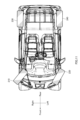
- FIG. 11 is a diagram showing the state of the wheels in the normal running mode.
- the wheels supension units
- the wheels are in a neutral state in which the front and rear wheels face in the straight forward direction of the vehicle.
- shift position "D” if the driver leaves the steering wheel 12 in the straight ahead position (neutral position) and steps on the accelerator pedal, the vehicle will move forward in a straight line.
- shift position "R” if the driver leaves the steering wheel 12 in the straight ahead position (neutral position) and steps on the accelerator pedal, the vehicle will move backward in a straight line.
- FIG. 12 is a diagram showing the operation touch panel in the rotate on the spot mode.
- the shift position "P" is selected, it becomes possible to select a special drive mode.
- an operation area 71 is displayed on the operation touch panel 70, and as shown in FIG. 12, it is displayed that the mode is the "rotate on the spot mode”.
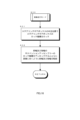
- Figure 13 is a flowchart that the controller executes in rotate mode.
- step S21 the controller locks the lock mechanism of the steering gear box 100 with the steering gear box 100 in the neutral position. This fixes the pinion gear.
- a command sound may be issued to the driver or a command lamp may be turned on/off to command the driver to move the steering wheel to the neutral position.
- the position of the rack bar 102 may also be adjusted by the power steering device.
- step S22 the controller unlocks the locking mechanisms of the front and rear wheel suspension assemblies, steers the right front wheel to the left, the left front wheel to the right, the right rear wheel in the same direction as the left front wheel, and the left rear wheel in the same direction as the right front wheel.
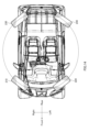
- FIG. 14 is a diagram showing the state of the wheels in the rotate on the spot mode.
- the wheels supension units
- the wheels become as shown in Fig. 14. That is, the right front wheel is steered to the left by a predetermined angle with respect to a straight-ahead state, the left front wheel is steered to the right by a predetermined angle with respect to a straight-ahead state, the right rear wheel is steered to the same direction as the left front wheel by a predetermined angle with respect to a straight-ahead state, and the left rear wheel is steered to the same direction as the right front wheel by a predetermined angle with respect to a straight-ahead state.
- FIG. 15 is a diagram showing the operation touch panel in the parallel mode.
- the driver selects the "parallel mode”
- an operation area 71 is displayed on the operation touch panel 70, and as shown in FIG. 15, the "parallel mode” is displayed.
- FIG 16 is a flowchart that the controller executes in parallel mode 1.
- step S31 the controller locks the lock mechanism of the steering gear box 100 when the steering gear box 100 is in the neutral position. This fixes the pinion gear.
- a command sound can be emitted to the driver or a command lamp can be turned on/off to command the driver to move the steering wheel to the neutral position.
- the position of the rack bar 102 can also be adjusted by the power steering device.
- step S32 the controller unlocks the locking mechanisms of the front and rear wheel suspension assemblies and steers the front and rear wheels so that they face straight to the side.
- FIG. 17 is a diagram showing the state of the wheels in the parallel mode 1.
- the wheels supension units
- the wheels become as shown in Fig. 17. That is, the right front wheel is steered about 90 degrees to the left with respect to the straight-ahead state and is in a straight-ahead state, the left front wheel is steered about 90 degrees to the right with respect to the straight-ahead state and is in a straight-ahead state, the right rear wheel is steered about 90 degrees in the same direction as the left front wheel with respect to the straight-ahead state and is in a straight-ahead state, and the left rear wheel is steered about 90 degrees in the same direction as the right front wheel with respect to the straight-ahead state and is in a straight-ahead state.
- the front and rear wheels are turned about 90 degrees from the straight-ahead position to a straight-ahead position, and equal driving force is generated on all four wheels, making straight-ahead driving possible.
- Figure 19 is a flowchart that the controller executes in parallel mode 2.
- the vehicle In parallel mode 1, the vehicle is a four-wheel drive type or a two-wheel drive type (front-wheel drive type/rear-wheel drive type). In contrast, in parallel mode 2, the vehicle is a two-wheel drive type (front-wheel drive type/rear-wheel drive type).
- front-wheel drive type In parallel mode 1, the vehicle is a four-wheel drive type or a two-wheel drive type (front-wheel drive type/rear-wheel drive type).
- the vehicle In parallel mode 1, the vehicle is a four-wheel drive type or a two-wheel drive type (front-wheel drive type/rear-wheel drive type).
- the vehicle In parallel mode 2, the vehicle is a two-wheel drive type (front-wheel drive type/rear-wheel drive type).
- front-wheel drive type in which the front wheels are drive wheels and the rear wheels are passive wheels.
- step S310 the controller locks the locking mechanism of the steering gear box 100 when the steering gear box 100 is in the neutral position. This fixes the pinion gear.
- a command sound can be emitted to the driver or a command lamp can be turned on/off to instruct the driver to move the steering wheel to the neutral position.
- the position of the rack bar 102 can also be adjusted by the power steering device.
- step S320 the controller unlocks the locking mechanisms of the front and rear wheel suspension assemblies and steers the front wheels more than 90 degrees from a straight-ahead state.
- the wheels are steered a few degrees beyond 90 degrees. In this way, the right and left front wheels will be positioned further forward on the vehicle the further they are from the vehicle centerline.
- the rear wheels are also steered about 90 degrees from a straight-ahead state. Although it depends on the vehicle specifications, the wheels are steered a few degrees before 90 degrees where the rear wheels are directly to the side, or to 90 degrees where the rear wheels are directly to the side. In this way, the right and left rear wheels will be positioned further forward on the vehicle or directly to the side the further they are from the vehicle centerline.
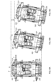
- FIG. 20A to 20C are diagrams showing the state of the wheels when the parallel mode 2 is executed.
- the wheels which were initially moving straight as shown in FIG. 20A, become as follows. That is, as shown in FIG. 20B, the right front wheel is steered to the left relative to a straight-ahead state, the left front wheel is steered to the right relative to a straight-ahead state, the right rear wheel is steered in the same direction as the left front wheel relative to a straight-ahead state, and the left rear wheel is steered in the same direction as the right front wheel relative to a straight-ahead state. Furthermore, as shown in FIG.
- the right front wheel is steered to the left by several degrees beyond 90 degrees from the straight-ahead state
- the left front wheel is steered to the right by several degrees beyond 90 degrees from the straight-ahead state. That is, the right front wheel and the left front wheel are positioned closer to the front of the vehicle as they are further from the vehicle center line CL.
- the right rear wheel is steered to about several degrees before 90 degrees or about 90 degrees in the same direction as the left front wheel as compared to the straight-ahead state
- the left rear wheel is steered to about several degrees before 90 degrees or about 90 degrees in the same direction as the right front wheel as compared to the straight-ahead state.
- the right rear wheel and the left rear wheel are positioned closer to the front of the vehicle or are directed straight to the side as they are further from the vehicle center line CL.
- the wheels are shown in a deformed state in which they are steered from the straight-ahead state to a greater extent than the actual steering angle.
- the right front wheel (drive wheel) and the left front wheel (drive wheel) rotate in the opposite direction to when the vehicle runs straight to the right, and the vehicle runs straight to the left.
- FIG. 22 is a flow chart showing the operations performed by the controller in the slanting mode.
- step S41 the controller locks the locking mechanism of the front wheel suspension assembly when the front wheel is in the neutral position in a straight-ahead state.
- step S42 the controller unlocks the locking mechanism of the steering gear box 100.
- step S43 the controller unlocks the locking mechanism of the rear wheel suspension assembly and steers the rear wheels in the same direction as the front wheels in accordance with the driver's steering wheel operation amount (the steering amount of the steering gear box).
- FIG. 23 is a diagram showing the state of the wheels in the slanting mode.
- the wheels are as shown in FIG. 23. That is, the front wheels are steered by the driver's steering wheel operation.
- the rear wheels are steered in the same direction as the front wheels by the actuator of the rear wheel suspension unit in accordance with the driver's steering wheel operation amount.
- the same driving force can be generated for the four wheels, so that diagonal running is possible by steering the rear wheels in the same manner as the front wheels.
- FIG. 24 is a flow chart that the controller executes in the small turn mode.
- step S51 the controller locks the locking mechanism of the front wheel suspension assembly when the front wheel is in the neutral position for straight ahead driving.
- step S52 the controller unlocks the locking mechanism of the steering gear box 100.
- step S53 the controller unlocks the locking mechanism of the rear wheel suspension assembly and steers the rear wheels in the opposite direction to the front wheels in accordance with the driver's steering wheel operation amount (the steering amount of the steering gear box).
- FIG. 25 is a diagram showing the state of the wheels in the small turn mode.
- the wheels supension units
- the front wheels are steered by the driver's steering wheel operation.
- the rear wheels are steered in the opposite direction to the front wheels by the actuator of the rear wheel suspension unit in accordance with the amount of steering wheel operation by the driver.
- the right rear wheel is steered in the opposite direction at an angle approximately equal to the steering angle of the right front wheel with respect to the neutral position.
- the left rear wheel is steered in the opposite direction at an angle approximately equal to the steering angle of the left front wheel with respect to the neutral position.
- the suspension is unitized and the suspension unit is assembled to the vehicle body frame 1 by inserting the shaft portion 411 of the suspension unit into a hole in the vehicle body frame 1, making assembly easy and improving productivity.
- Some suspension units have a built-in motor, while others do not, but the basic configuration is the same, making it easy to mass-produce.
- Electromagnetic brakes are suitable as locking mechanisms for suspension assemblies. Electromagnetic brakes are also suitable as locking mechanisms for steering gear boxes, as they are small, lightweight, and easy to control.
- the electromagnetic brake used in the suspension assembly is preferably a type that operates in a de-energized state to enter a locked state, and is released and unlocked when energized.
- the electromagnetic brake used in the steering gearbox is preferably a type that operates in a powered state to enter a locked state, and is released and unlocked when de-energized. In this way, in normal driving mode, both the electromagnetic brake used in the suspension assembly and the electromagnetic brake used in the steering gearbox are in a de-energized state.
- the normal driving mode lasts for a longer period of time than the special driving mode, which leads to energy savings.
- a double wishbone type suspension system is exemplified.
- the technical scope of the present invention be limited to the double wishbone type.
- it may be applied to a strut type, a multi-link type, etc.
Landscapes
- Engineering & Computer Science (AREA)
- Mechanical Engineering (AREA)
- Chemical & Material Sciences (AREA)
- Combustion & Propulsion (AREA)
- Transportation (AREA)
- Vehicle Body Suspensions (AREA)
Priority Applications (1)
| Application Number | Priority Date | Filing Date | Title |
|---|---|---|---|
| JP2025550860A JPWO2025074887A1 (https=) | 2023-10-05 | 2024-09-21 |
Applications Claiming Priority (4)
| Application Number | Priority Date | Filing Date | Title |
|---|---|---|---|
| JP2023173760 | 2023-10-05 | ||
| JP2023-173760 | 2023-10-05 | ||
| JP2023198574 | 2023-11-22 | ||
| JP2023-198574 | 2023-11-22 |
Publications (1)
| Publication Number | Publication Date |
|---|---|
| WO2025074887A1 true WO2025074887A1 (ja) | 2025-04-10 |
Family
ID=95283213
Family Applications (1)
| Application Number | Title | Priority Date | Filing Date |
|---|---|---|---|
| PCT/JP2024/033783 Pending WO2025074887A1 (ja) | 2023-10-05 | 2024-09-21 | ステアリングギアボックス及びサスペンションアッセンブリー及びステアリングシステム |
Country Status (2)
| Country | Link |
|---|---|
| JP (1) | JPWO2025074887A1 (https=) |
| WO (1) | WO2025074887A1 (https=) |
Citations (13)
| Publication number | Priority date | Publication date | Assignee | Title |
|---|---|---|---|---|
| JPS57174270U (https=) * | 1981-04-30 | 1982-11-02 | ||
| JPS62251277A (ja) * | 1986-04-22 | 1987-11-02 | Mitsubishi Electric Corp | 電動式後輪操舵装置 |
| JPH03178832A (ja) * | 1989-12-06 | 1991-08-02 | Shikoku Sogo Kenkyusho:Kk | 電気自動車 |
| JPH05124534A (ja) * | 1991-11-08 | 1993-05-21 | Nippondenso Co Ltd | 車両の操舵装置 |
| JP2004268754A (ja) * | 2003-03-10 | 2004-09-30 | Honda Motor Co Ltd | ステアバイワイヤ式操舵装置 |
| CN102069843A (zh) * | 2011-01-05 | 2011-05-25 | 吉林大学 | 线控车轮独立转向执行机构及车轮总成 |
| JP2012121391A (ja) * | 2010-12-07 | 2012-06-28 | Ntn Corp | ステアリング装置 |
| JP2013103665A (ja) * | 2011-11-16 | 2013-05-30 | Nissan Motor Co Ltd | インホイールモータ駆動車輪の転舵装置 |
| JP2013144509A (ja) * | 2012-01-16 | 2013-07-25 | Nissan Motor Co Ltd | インホイールモータ駆動車輪のモータ給電線配索構造 |
| CN103895697A (zh) * | 2014-04-16 | 2014-07-02 | 中国科学院深圳先进技术研究院 | 一种电动汽车四轮独立转向底盘系统及其线控转向机构 |
| JP2015131618A (ja) * | 2014-01-15 | 2015-07-23 | 本田技研工業株式会社 | 電動式転舵装置搭載車両 |
| JP2018202923A (ja) * | 2017-05-31 | 2018-12-27 | 株式会社東海理化電機製作所 | ロック装置 |
| WO2020145166A1 (ja) * | 2019-01-08 | 2020-07-16 | 株式会社Fomm | サスペンションユニット及び車両 |
-
2024
- 2024-09-21 JP JP2025550860A patent/JPWO2025074887A1/ja active Pending
- 2024-09-21 WO PCT/JP2024/033783 patent/WO2025074887A1/ja active Pending
Patent Citations (13)
| Publication number | Priority date | Publication date | Assignee | Title |
|---|---|---|---|---|
| JPS57174270U (https=) * | 1981-04-30 | 1982-11-02 | ||
| JPS62251277A (ja) * | 1986-04-22 | 1987-11-02 | Mitsubishi Electric Corp | 電動式後輪操舵装置 |
| JPH03178832A (ja) * | 1989-12-06 | 1991-08-02 | Shikoku Sogo Kenkyusho:Kk | 電気自動車 |
| JPH05124534A (ja) * | 1991-11-08 | 1993-05-21 | Nippondenso Co Ltd | 車両の操舵装置 |
| JP2004268754A (ja) * | 2003-03-10 | 2004-09-30 | Honda Motor Co Ltd | ステアバイワイヤ式操舵装置 |
| JP2012121391A (ja) * | 2010-12-07 | 2012-06-28 | Ntn Corp | ステアリング装置 |
| CN102069843A (zh) * | 2011-01-05 | 2011-05-25 | 吉林大学 | 线控车轮独立转向执行机构及车轮总成 |
| JP2013103665A (ja) * | 2011-11-16 | 2013-05-30 | Nissan Motor Co Ltd | インホイールモータ駆動車輪の転舵装置 |
| JP2013144509A (ja) * | 2012-01-16 | 2013-07-25 | Nissan Motor Co Ltd | インホイールモータ駆動車輪のモータ給電線配索構造 |
| JP2015131618A (ja) * | 2014-01-15 | 2015-07-23 | 本田技研工業株式会社 | 電動式転舵装置搭載車両 |
| CN103895697A (zh) * | 2014-04-16 | 2014-07-02 | 中国科学院深圳先进技术研究院 | 一种电动汽车四轮独立转向底盘系统及其线控转向机构 |
| JP2018202923A (ja) * | 2017-05-31 | 2018-12-27 | 株式会社東海理化電機製作所 | ロック装置 |
| WO2020145166A1 (ja) * | 2019-01-08 | 2020-07-16 | 株式会社Fomm | サスペンションユニット及び車両 |
Also Published As
| Publication number | Publication date |
|---|---|
| JPWO2025074887A1 (https=) | 2025-04-10 |
Similar Documents
| Publication | Publication Date | Title |
|---|---|---|
| JP4636256B2 (ja) | 転舵装置 | |
| US8701801B2 (en) | Electric vehicle | |
| US7644938B2 (en) | In-wheel suspension | |
| JP6351944B2 (ja) | ステアリング装置 | |
| JP6382545B2 (ja) | ステアリング装置及びそれを備えた車両 | |
| JP2007055409A5 (https=) | ||
| JP2012121391A (ja) | ステアリング装置 | |
| JP2020097291A (ja) | 特殊転舵装置を備えた車両 | |
| WO2015076253A1 (ja) | 車両 | |
| JPH06183365A (ja) | 車両用懸架装置 | |
| CN108297930B (zh) | 一种转向及悬架系统 | |
| JPH04103467A (ja) | 電気自動車 | |
| JPH05124535A (ja) | 車両用懸架装置 | |
| WO2025074887A1 (ja) | ステアリングギアボックス及びサスペンションアッセンブリー及びステアリングシステム | |
| JP2021098406A (ja) | 転舵装置 | |
| US20070175695A1 (en) | Steering gear | |
| WO2016039312A1 (ja) | ステアリング装置、及び車両の走行モードの切り替え方法 | |
| JP2011225128A (ja) | 車両用ステアリングシステム | |
| CN118991926A (zh) | 一种适用于双横臂悬架无人车辆的转向杆系布置方法 | |
| JP2017007633A (ja) | ステアリング装置、及び車両の走行モードの切り替え方法 | |
| JP4624151B2 (ja) | 自動車の操舵装置 | |
| JP2016055804A (ja) | ステアリング装置及び車両の走行モードの切り替え方法 | |
| JPS6150831B2 (https=) | ||
| JPWO2025074887A5 (https=) | ||
| JPH0343113B2 (https=) |
Legal Events
| Date | Code | Title | Description |
|---|---|---|---|
| 121 | Ep: the epo has been informed by wipo that ep was designated in this application |
Ref document number: 24874496 Country of ref document: EP Kind code of ref document: A1 |
|
| DPE1 | Request for preliminary examination filed after expiration of 19th month from priority date (pct application filed from 20040101) | ||
| ENP | Entry into the national phase |
Ref document number: 2025550860 Country of ref document: JP Kind code of ref document: A |
|
| WWE | Wipo information: entry into national phase |
Ref document number: 2025550860 Country of ref document: JP |