WO2025074751A1 - 車両用駆動装置 - Google Patents
車両用駆動装置 Download PDFInfo
- Publication number
- WO2025074751A1 WO2025074751A1 PCT/JP2024/029289 JP2024029289W WO2025074751A1 WO 2025074751 A1 WO2025074751 A1 WO 2025074751A1 JP 2024029289 W JP2024029289 W JP 2024029289W WO 2025074751 A1 WO2025074751 A1 WO 2025074751A1
- Authority
- WO
- WIPO (PCT)
- Prior art keywords
- stator core
- tube member
- case
- flow path
- drive device
- Prior art date
- Legal status (The legal status is an assumption and is not a legal conclusion. Google has not performed a legal analysis and makes no representation as to the accuracy of the status listed.)
- Pending
Links
Images



Classifications
-
- H—ELECTRICITY
- H02—GENERATION; CONVERSION OR DISTRIBUTION OF ELECTRIC POWER
- H02K—DYNAMO-ELECTRIC MACHINES
- H02K1/00—Details of the magnetic circuit
- H02K1/06—Details of the magnetic circuit characterised by the shape, form or construction
- H02K1/12—Stationary parts of the magnetic circuit
- H02K1/20—Stationary parts of the magnetic circuit with channels or ducts for flow of cooling medium
-
- H—ELECTRICITY
- H02—GENERATION; CONVERSION OR DISTRIBUTION OF ELECTRIC POWER
- H02K—DYNAMO-ELECTRIC MACHINES
- H02K9/00—Arrangements for cooling or ventilating
- H02K9/19—Arrangements for cooling or ventilating for machines with closed casing and closed-circuit cooling using a liquid cooling medium, e.g. oil
Definitions
- the present invention relates to a vehicle drive system.
- a rotating electric machine that has a refrigerant flow passage through which a refrigerant for cooling a stator core flows.
- a rotating electric machine is disclosed, for example, in International Publication No. 2020/213052.
- WO 2020/213052 discloses a rotating electric machine in which a cooling liquid flow path (refrigerant flow path) is formed through which a cooling liquid (refrigerant) for cooling a stator core flows.
- a rotor and a stator including a stator core are housed in a housing (case).
- the housing has a double-wall structure consisting of an inner housing and an outer housing in order to form a cooling liquid flow path inside the housing through which a cooling liquid for cooling the stator core flows.
- a vehicle drive device in one aspect of the present invention includes a rotor, a stator arranged to face the outer peripheral surface of the rotor and having a stator core, a rotating electric machine that functions as a driving force source for the wheels, a resin tube member that covers at least the outer peripheral surface of the stator core, and a case that houses the rotating electric machine and the tube member, and a refrigerant flow path is formed between the tube member and the case through which a refrigerant for cooling the stator core flows.
- the vehicle drive device includes a rotating electric machine including a stator having a stator core, a resin tube member covering at least the outer peripheral surface of the stator core, and a case housing the rotating electric machine and the tube member, and a refrigerant flow path through which a refrigerant for cooling the stator core flows is formed between the tube member and the case.
- a rotating electric machine including a stator having a stator core, a resin tube member covering at least the outer peripheral surface of the stator core, and a case housing the rotating electric machine and the tube member, and a refrigerant flow path through which a refrigerant for cooling the stator core flows is formed between the tube member and the case.
- the tube member In a configuration in which the tube member covers the outer peripheral surface of the stator core as well as at least one of the end faces on one side and the other side in the axial direction of the stator core, the tube member preferably covers the outer peripheral surface of the stator core as well as one end face in the axial direction of the stator core, and further includes a seal member that seals between the case and a one-side cover portion of the tube member that covers the end face on one side in the axial direction of the stator core.
- the sealing member seals between the case and one-side cover portion of the tube member that covers one end face of the stator core in the axial direction, thereby further improving the sealing performance between the stator core and the refrigerant flow path provided by the tube member.
- the tube member is preferably a heat-shrinkable tube member.
- the tube member can be heated to shrink it, and thereby the tube member can be brought into close contact with at least the outer peripheral surface of the stator core.
- the cooling performance of the refrigerant passing through the tube member covering the outer peripheral surface of the stator core can be improved compared to when the tube member is not heat-shrinkable.
- the stator core includes a fastening protruding portion protruding toward the outer periphery and having a core through hole through which a fastening member for fixing the stator core to the case passes, and the tube member covers the outer periphery of the stator core including the outer periphery of the fastening protruding portion.
- This configuration makes it possible to form a refrigerant flow path through which a refrigerant flows to cool the stator core, including the fastening protrusions, while preventing the case from becoming too large and preventing the case structure from becoming too complicated.
- a first sealing member groove for positioning the sealing member is preferably formed in the portion of the case facing the one side covering portion of the tube member, and an O-ring as a sealing member is positioned in the first sealing member groove.
- the O-ring which acts as a sealing member and is placed in the groove for the first sealing member, can easily seal between the case and one of the covering portions of the tube member.
- the tube member covers not only the outer peripheral surface of the stator core and one axial end face of the stator core, but also the other axial end face of the stator core, and a lip seal member formed by vulcanization welding a resin member having a tongue-shaped tip to a metal plate member is disposed in a portion facing the one side covering portion covering the one axial end face of the tube member in the space including the refrigerant flow path between the case and the tube member.
- the lip seal member which acts as a sealing member and is arranged in a portion facing the one side cover portion of the tube member in the space including the refrigerant flow path between the case and the tube member, can easily seal between the case and the one side cover portion of the tube member.
- the configuration further includes an annular plate-shaped member that is arranged on the other axial end face side of the stator core and forms a refrigerant flow path together with the tube member and the case, and a second sealing member groove for arranging the sealing member is formed in a portion of the plate-shaped member facing the other axial covering portion that covers the other axial end face of the tube member, and a third sealing member groove for arranging the sealing member is formed in a portion of the plate-shaped member facing the case, and a second O-ring and a third O-ring are arranged as sealing members in the second sealing member groove and the third sealing member groove, respectively.
- the second O-ring which acts as a seal member and is placed in the groove for the second seal member, can easily seal between the plate-like member and the other side cover portion of the tube member.
- the third O-ring which acts as a seal member and is placed in the groove for the third seal member, can easily seal between the plate-like member and the case.
- the stator core further includes an annular plate-shaped member arranged on the other axial end face side of the stator core, having a fastening through hole through which a fastening member for fixing the stator core to the case passes, and forming a refrigerant flow path together with the tube member and the case, and the stator core is fixed to the case by fastening it to the case with the fastening member, with the plate-shaped member arranged on the other axial end face side of the stator core so as to form a refrigerant flow path.
- the stator core can be easily fixed to the case by the annular plate member arranged on the other axial end face side of the stator core, while forming a refrigerant flow path together with the tube member and the case. Also, because the stator core is fixed to the case by being fastened to the case with the fastening member, no compressive stress is applied to the stator core compared to when the stator core is fixed to the case by being shrink-fitted to the case. Therefore, it is possible to suppress an increase in iron loss (energy loss) caused by compressive stress applied to the stator core when the rotor rotates, and therefore a decrease in electricity consumption can be suppressed.
- iron loss energy loss
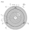
- the configuration of a vehicle drive device 100 according to a first embodiment of the present invention will be described with reference to Figures 1 to 4.
- the vehicle drive device 100 is a drive device used in, for example, electric vehicles, hybrid vehicles, and the like.
- the vehicle drive device 100 includes a rotating electric machine RE including a rotor 10 and a stator 20, a tube member 30, a case 40, and a plate-shaped member 50.
- the rotating electric machine RE is, for example, a motor, a generator, or a motor/generator.
- the rotating electric machine RE functions as a driving force source for the wheels.
- the stator 20 is disposed on the R2 side of the rotor 10 (rotor core 11) so as to face the outer peripheral surface 10a of the rotor 10. That is, the rotating electric machine RE is an inner rotor type rotating electric machine.
- the stator 20 has a stator core 21 and a coil (not shown).
- the stator core 21 is formed in an annular shape.
- the stator core 21 is formed by laminating a plurality of electromagnetic steel plates.
- the coil (not shown) is wound around the stator core 21.
- the stator core 21 includes a fastening protruding portion 21a that protrudes toward the outer periphery (R2 side).
- a core through hole 21b is formed in the fastening protruding portion 21a.
- a fastening member 60 for fixing the stator core 21 to the case 40 passes through the core through hole 21b.
- FIG. 1 shows an example in which the fastening member 60 is a bolt.
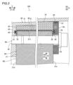
- the tube member 30 covers the end face 21d on one side (Z1 side) and the end face 21e on the other side (Z2 side) in the axial direction (Z direction) of the stator core 21 in addition to the outer peripheral surface 21c of the stator core 21. Specifically, the tube member 30 covers the entire outer peripheral surface 21c of the stator core 21, including the outer peripheral surface of the fastening protrusion 21a. The tube member 30 also covers the R2 side portion of the Z1 side end face 21d of the stator core 21. The tube member 30 also covers the R2 side portion of the Z2 side end face 21e of the stator core 21.
- the tube member 30 is made of resin.
- the tube member 30 is a heat-shrinkable tube member.
- the tube member 30 preferably has a continuous use temperature (long-term heat resistance temperature) of 200°C or higher.
- the tube member 30 has a thickness of at least 1000 ⁇ m, and preferably has a thickness of 20 ⁇ m or more and 500 ⁇ m or less.
- the tube member 30 is, for example, a fluororesin such as PFA (Per Fluoro Alkoxy Polymer) or FEP (Fluorinated Ethylene Propylene).
- the case 40 houses the rotating electric machine RE and the tube member 30.
- the case 40 is made of a metal such as aluminum.
- a cooling water flow path 70 is formed between the tube member 30 and the case 40. Specifically, as shown in FIG. 3, the cooling water flow path 70 is formed between an outer peripheral surface covering portion 31 of the tube member 30 that covers the outer peripheral surface 21c of the stator core 21 and a tube member facing portion 41 of the case 40 that faces the outer peripheral surface covering portion 31 of the tube member 30 in the R direction. Cooling water for cooling the stator core 21 flows through the cooling water flow path 70.
- the cooling water is, for example, a liquid containing a component having an antifreeze effect.
- the cooling water flow path 70 and the cooling water are examples of a "refrigerant flow path" and a "refrigerant” in the claims, respectively.
- the cooling water flow passage 70 is formed in a ring shape.
- the width W1 of the portion of the cooling water flow passage 70 where the fastening protrusion 21a of the stator core 21 is present is smaller than the width W2 of the portion of the cooling water flow passage 70 where the fastening protrusion 21a of the stator core 21 is not present.
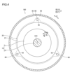
- the plate-shaped member 50 is disposed on the end face 21e side on the other side (Z2 side) in the axial direction (Z direction) of the stator core 21.
- the plate-shaped member 50 is formed in an annular shape.
- the plate-shaped member 50 forms a cooling water flow path 70 together with the tube member 30 and the case 40.
- the plate-shaped member 50 contacts the other side cover portion 32 of the tube member 30 that covers the end face 21e on the Z2 side of the stator core 21, and the portion of the end face 21e on the Z2 side of the stator core 21 that is not covered by the tube member 30.
- the plate-shaped member 50 is formed to extend in the R direction. An end portion 51 on the R2 side of the plate-shaped member 50 contacts the case 40. That is, the Z2 side end portion of the cooling water flow path 70 formed by the outer peripheral surface cover portion 31 of the tube member 30 and the tube member facing portion 41 of the case 40 is blocked by the plate-shaped member 50. The Z1 side end of the cooling water flow path 70 formed by the outer peripheral surface covering portion 31 of the tube member 30 and the tube member opposing portion 41 of the case 40 is blocked by a one-side covering portion 33 of the tube member 30 covering the Z1 side end face 21d of the stator core 21 contacting a surface 42 of the case 40 extending along the RC plane.
- the plate-shaped member 50 has fastening through holes 52 through which fastening members 60 for fixing the stator core 21 to the case 40 penetrate.
- the stator core 21 is fixed to the case 40 by fastening the plate-shaped member 50 to the case 40 with the fastening members 60, with the plate-shaped member 50 arranged on the end face 21e side on the other side (Z2 side) of the axial direction (Z direction) of the stator core 21 so as to form a cooling water flow path 70.
- a fastening hole 44 into which the tip of the fastening member 60 is inserted is formed in a portion 43 of the case 40 arranged on the Z1 side of the stator core 21 having a surface 42 extending along the RC plane.
- the fastening hole 44 has a female thread formed therein that engages with a male thread formed on the tip of the fastening member 60. Then, the portion 43 of the case 40, the stator core 21, and the plate-shaped member 50 are arranged in this order from the Z1 side toward the Z2 side so that the fastening hole portion 44 of the case 40, the core through hole 21b of the stator core 21, and the fastening through hole 52 of the plate-shaped member 50 overlap when viewed from the Z direction. Then, the fastening member 60 is inserted from the Z2 side of the plate-shaped member 50 through the fastening through hole 52 of the plate-shaped member 50 and the core through hole 21b of the stator core 21. Then, the male thread formed at the tip of the fastening member 60 is engaged with the female thread formed in the fastening hole portion 44 of the case 40.
- the vehicle drive device 100 includes a seal member that seals between the case 40 and the one side cover portion 33 of the tube member 30. Specifically, a first seal member groove 45 for arranging the seal member is formed in a portion of the case 40 that faces the one side cover portion 33. A first O-ring 81 serving as a seal member is arranged in the first seal member groove 45.
- the vehicle drive device 100 includes a seal member that seals between the plate member 50 and the other side cover portion 32 of the tube member 30.
- a second seal member groove 53 for arranging the seal member is formed in the portion of the plate member 50 that faces the other side cover portion 32 of the tube member 30.
- a second O-ring 82 serving as a seal member is arranged in the second seal member groove 53.
- the vehicle drive device 100 includes a seal member that seals between the plate-shaped member 50 and the case 40.
- a third seal member groove 54 for arranging the seal member is formed in the portion of the plate-shaped member 50 that faces the case 40 (the portion of the plate-shaped member 50 that contacts the case 40).
- a third O-ring 83 serving as a seal member is arranged in the third seal member groove 54.
- the vehicle drive device 100 includes a rotating electric machine RE including a stator 20 having a stator core 21, a resin tube member 30 covering at least the outer peripheral surface 21c of the stator core 21, and a case 40 housing the rotating electric machine RE and the tube member 30.
- a cooling water flow path 70 through which cooling water for cooling the stator core 21 flows is formed between the tube member 30 and the case 40.
- the outer peripheral surface 21c of the stator core 21 and the cooling water flow path 70 are adjacent to each other via the resin tube member 30, so that the cooling water flow path 70 can be formed without making the case 40 a double-wall structure.
- the cooling water flow path 70 through which cooling water for cooling the stator core 21 flows can be formed while preventing the case 40 from becoming large and preventing the structure of the case 40 from becoming complicated.
- the resin tube member 30 generally does not allow liquid to pass through even when it has a very thin thickness (for example, on the order of ⁇ m). Therefore, even if the tube member 30 is made of resin, which has a very low thermal conductivity compared to metals, by using a resin tube member 30 with a very thin thickness (for example, on the order of ⁇ m), the stator core 21 can be sufficiently cooled by the cooling water flowing through the cooling water flow path 70.
- the tube member 30 covers the outer peripheral surface 21c of the stator core 21, as well as the end face 21d on one side (Z1 side) and the end face 21e on the other side (Z2 side) in the axial direction (Z direction) of the stator core 21. This improves the sealing performance between the stator core 21 and the cooling water flow path 70 by the tube member 30, compared to when the tube member 30 covers only the outer peripheral surface 21c of the stator core 21.
- the vehicle drive device 100 includes a seal member (first O-ring 81) that seals between the case 40 and one-side cover portion 33 of the tube member 30 that covers the end face 21d on one side (Z1 side) in the axial direction (Z direction) of the stator core 21.
- first O-ring 81 seals between the case 40 and one-side cover portion 33 of the tube member 30 that covers the end face 21d on one side (Z1 side) in the axial direction (Z direction) of the stator core 21.
- the tube member 30 is a tube member having heat shrinkability. This allows the tube member 30 to be attached closely to at least the outer peripheral surface 21c of the stator core 21 by applying heat to the tube member 30 to cause it to shrink. As a result, the cooling performance of the cooling water passing through the tube member 30 covering the outer peripheral surface 21c of the stator core 21 can be improved compared to when the tube member 30 is a tube member that does not have heat shrinkability.
- the stator core 21 includes a fastening protrusion 21a that protrudes outward (toward the R2 side) and has a core through hole 21b through which a fastening member 60 for fixing the stator core 21 to the case 40 passes.
- the tube member 30 covers the outer peripheral surface 21c of the stator core 21, including the outer peripheral surface of the fastening protrusion 21a. This makes it possible to form a cooling water flow path 70 through which cooling water for cooling the stator core 21 including the fastening protrusion 21a flows, while preventing the case 40 from becoming larger and preventing the structure of the case 40 from becoming complicated.
- a first seal member groove 45 for arranging a seal member is formed in a portion of the case 40 facing the one side cover portion 33 of the tube member 30.
- a first O-ring 81 serving as a seal member is arranged in the first seal member groove 45. This makes it possible to easily seal between the case 40 and the one side cover portion 33 of the tube member 30 by the first O-ring 81 serving as a seal member arranged in the first seal member groove 45.
- the vehicle drive device 100 includes an annular plate member 50 disposed on the end face 21e of the other side (Z2 side) in the axial direction (Z direction) of the stator core 21, and forming a cooling water flow path 70 together with the tube member 30 and the case 40.
- a second seal member groove 53 for arranging a seal member is formed in a portion of the plate member 50 facing the other side cover portion 32 that covers the end face 21e of the other side (Z2 side) in the axial direction (Z direction) of the tube member 30.
- a third seal member groove 54 for arranging a seal member is formed in a portion of the plate member 50 facing the case 40.
- a second O-ring 82 and a third O-ring 83 are disposed as seal members in the second seal member groove 53 and the third seal member groove 54, respectively.
- the third O-ring 83 which serves as a seal member arranged in the third seal member groove 54, allows easy sealing between the plate member 50 and the case 40.
- the vehicle drive device 100 includes an annular plate member 50 that is disposed on the end face 21e of the other side (Z2 side) in the axial direction (Z direction) of the stator core 21, has a fastening through hole 52 through which a fastening member 60 for fixing the stator core 21 to the case 40 passes, and forms a cooling water flow path 70 together with the tube member 30 and the case 40.
- the stator core 21 is fixed to the case 40 by being fastened to the case 40 by the fastening member 60 in a state in which the plate member 50 is disposed on the end face 21e of the other side (Z2 side) in the axial direction (Z direction) of the stator core 21 so as to form the cooling water flow path 70.
- the annular plate member 50 disposed on the end face 21e of the other side (Z2 side) in the axial direction (Z direction) of the stator core 21 can easily fix the stator core 21 to the case 40 while forming the cooling water flow path 70 together with the tube member 30 and the case 40.
- the stator core 21 is fixed to the case 40 by fastening it to the case 40 with the fastening members 60, the stator core 21 is not subjected to compressive stress, as compared to when the stator core 21 is fixed to the case 40 by shrink fitting it to the case 40. Therefore, when the rotor 10 rotates, the increase in iron loss (energy loss) caused by the compressive stress applied to the stator core 21 can be suppressed, and the decrease in electric power consumption can be suppressed.
- the vehicle drive device 200 includes a rotating electric machine RE including a rotor 10 and a stator 20 , a tube member 30 , a case 240 , and a plate-shaped member 50 .
- the tube member 30 covers the outer peripheral surface 21c of the stator core 21, as well as the end face 21d on one side (Z1 side) and the end face 21e on the other side (Z2 side) in the axial direction (Z direction) of the stator core 21.
- the case 240 houses the rotor 10 and the stator 20.
- a cooling water flow path 70 is formed between the tube member 30 and the case 240. Cooling water for cooling the stator core 21 flows through the cooling water flow path 70.
- a lip seal member 280 is disposed in a portion of the tube member 30 facing the one-side cover portion 33 that covers the end face 21d on one side (Z1 side) in the axial direction (Z direction) of the stator core 21.
- the lip seal member 280 is a sealing member formed by vulcanization welding a resin member having a tongue-shaped tip to a metal plate-like member.
- the rest of the configuration of the vehicle drive device 200 of the second embodiment is similar to that of the vehicle drive device 100 of the first embodiment.
- the vehicle drive device 200 includes a rotating electric machine RE including a stator 20 having a stator core 21, a resin tube member 30 covering at least the outer peripheral surface 21c of the stator core 21, and a case 240 housing the rotating electric machine RE and the tube member 30.
- a cooling water flow path 70 through which cooling water for cooling the stator core 21 flows is formed between the tube member 30 and the case 240.
- the outer peripheral surface 21c of the stator core 21 and the cooling water flow path 70 are adjacent to each other via the resin tube member 30, so that the cooling water flow path 70 can be formed without making the case 240 a double-wall structure.
- the cooling water flow path 70 through which cooling water for cooling the stator core 21 flows can be formed while preventing the case 240 from becoming large and preventing the structure of the case 240 from becoming complicated.
- a lip seal member 280 is disposed in a portion of the tube member 30 that faces the one-side cover portion 33 that covers the end face 21d on one side (Z1 side) of the stator core 21 in the axial direction (Z direction) of the stator core 21 in the space including the cooling water flow path 70 between the case 240 and the tube member 30.
- the lip seal member 280 is disposed in a portion of the tube member 30 that faces the one-side cover portion 33 of the tube member 30 by vulcanization welding. This allows the lip seal member 280 to easily seal between the case 240 and the one-side cover portion 33 of the tube member 30. In this case, there is no need to form a groove for the seal member in the case 240 to place the seal member, and therefore the manufacturing process of the case 240 can be simplified.
- the vehicle driving device 100 (200) is arranged on the end face 21e side (Z2 side) of the stator core 21 in the axial direction (Z direction), has a fastening through hole 52 through which a fastening member 60 for fixing the stator core 21 to the case 40 (240), and is provided with an annular plate-shaped member 50 which forms a cooling water flow path 70 together with the tube member 30 and the case 40 (240), and the stator core 21 is fixed to the case 40 (240) by fastening it to the case 40 (240) with the fastening member 60, with the plate-shaped member 50 arranged on the end face 21e side (Z2 side) of the stator core 21 in the axial direction (Z direction) so that the cooling water flow path 70 is formed, but the present invention is not limited to this.
- the vehicle drive device 300 does not include an annular plate-shaped member 50 like the vehicle drive device 100 (200), and the stator core 21 may be fixed to the case 240 without being fastened to the case 240 by a fastening member 60.
- the vehicle drive device 300 includes a seal member 381 arranged near the Z1 side end of the cooling water flow path 70 formed by the outer peripheral surface covering portion 31 of the tube member 30 and the tube member facing portion 41 of the case 240, and a seal member 382 arranged at the Z2 side end of the cooling water flow path 70 formed by the outer peripheral surface covering portion 31 of the tube member 30 and the tube member facing portion 41 of the case 240.
- the vehicle drive device 100 (200) is arranged on the end face 21e side (Z2 side) of the stator core 21 in the axial direction (Z direction) and includes an annular plate-shaped member 50 which forms a cooling water flow path 70 together with the tube member 30 and the case 40 (240), and a second seal member groove 53 for arranging a seal member is formed in a portion of the plate member 50 facing the other side cover portion 32 which covers the end face 21e on the other side (Z2 side) of the tube member 30 in the axial direction (Z direction), and a third seal member groove 54 for arranging a seal member is formed in a portion of the plate member 50 facing the case 40 (240), and a second O-ring 82 and a third O-ring 83 are arranged as seal members in the second seal member groove 53 and the third seal member groove 54, respectively, but the present invention is not limited to this.
- the vehicle drive device 300 as in the modified example shown in FIG. 6, the vehicle drive device 300
- the tube member 30 is a tube member having heat shrinkability, but the present invention is not limited to this.
- the tube member 30 may be a tube member that does not have heat shrinkability.
- the vehicle drive device 100 (200) includes a seal member (first O-ring 81) that seals between the case 40 (240) and the one-side cover portion 33 of the tube member 30 that covers the end face 21d on one side (Z1 side) in the axial direction (Z direction) of the stator core 21, but the present invention is not limited to this.
- the vehicle drive device 100 (200) does not need to include a seal member (first O-ring 81) that seals between the case 40 (240) and the one-side cover portion 33 of the tube member 30 that covers the end face 21d on one side (Z1 side) in the axial direction (Z direction) of the stator core 21.
- the tube member 30 covers the end face 21d on one side (Z1 side) and the end face 21e on the other side (Z2 side) in the axial direction (Z direction) of the stator core 21 in addition to the outer peripheral surface 21c of the stator core 21, but the present invention is not limited to this.
- the tube member 30 may cover only one of the end face 21d on one side (Z1 side) and the end face 21e on the other side (Z2 side) in the axial direction (Z direction) of the stator core 21 in addition to the outer peripheral surface 21c of the stator core 21.
- the tube member 30 may cover the outer peripheral surface 21c of the stator core 21, but may not cover the end face 21d on one side (Z1 side) and the end face 21e on the other side (Z2 side) in the axial direction (Z direction) of the stator core 21.
- the "refrigerant” in the claims is cooling water, but the present invention is not limited to this.
- the "refrigerant” in the claims may be a refrigerant other than cooling water (for example, a refrigerant used in a heating and cooling device).
Landscapes
- Engineering & Computer Science (AREA)
- Power Engineering (AREA)
- Motor Or Generator Cooling System (AREA)
- Iron Core Of Rotating Electric Machines (AREA)
- Motor Or Generator Frames (AREA)
Abstract
この車両用駆動装置は、ステータコアを有するステータを含む回転電機と、ステータコアの少なくとも外周面を覆う樹脂製のチューブ部材と、回転電機およびチューブ部材を収容するケースと、を備え、チューブ部材とケースとの間にステータコアを冷却するための冷媒が流通する冷媒流路が形成されている。
Description
本発明は、車両用駆動装置に関する。
従来、ステータコアを冷却するための冷媒が流通する冷媒流路が形成された回転電機が知られている。このような回転電機は、たとえば、国際公開第2020/213052号に開示されている。
国際公開第2020/213052号には、ステータコアを冷却するための冷却液(冷媒)が流通する冷却液流路(冷媒流路)が形成された回転電機が開示されている。国際公開第2020/213052号に記載されている回転電機では、ハウジング(ケース)内に、ロータ、および、ステータコアを含むステータが収容されている。ハウジングは、ステータコアを冷却するための冷却液が流通する冷却液流路をハウジングの内部に形成するために、インナーハウジングとアウターハウジングとからなる二重壁構造を有する。
しかしながら、国際公開第2020/213052号では、ハウジング(ケース)は、冷却液流路(冷媒流路)を形成するために、インナーハウジングとアウターハウジングとからなる二重壁構造を有するので、ハウジングが比較的大きくなるとともに、ハウジングの構造が比較的複雑になる。このため、ハウジング(ケース)が大きくなるのを抑制しながら、かつ、ハウジングの構造が複雑になるのを抑制しながら、ステータコアを冷却するための冷却液(冷媒)が流通する冷却液流路(冷媒流路)を形成することが可能な構成が望まれている。
この発明は、上記のような課題を解決するためになされたものであり、この発明の1つの目的は、ケースが大きくなるのを抑制しながら、かつ、ケースの構造が複雑になるのを抑制しながらステータコアを冷却するための冷媒が流通する冷媒流路を形成することが可能な車両用駆動装置を提供することである。
上記目的を達成するために、この発明の一の局面における車両用駆動装置は、ロータと、ロータの外周面に対向するように配置され、ステータコアを有するステータと、を含み、車輪の駆動力源として機能する回転電機と、ステータコアの少なくとも外周面を覆う樹脂製のチューブ部材と、回転電機およびチューブ部材を収容するケースと、を備え、チューブ部材とケースとの間にステータコアを冷却するための冷媒が流通する冷媒流路が形成されている。
この発明の一の局面における車両用駆動装置は、上記のように、ステータコアを有するステータを含む回転電機と、ステータコアの少なくとも外周面を覆う樹脂製のチューブ部材と、回転電機およびチューブ部材を収容するケースと、を備え、チューブ部材とケースとの間にステータコアを冷却するための冷媒が流通する冷媒流路が形成されている。これにより、ステータコアの外周面と冷媒流路とが樹脂製のチューブ部材を介して隣接するので、ケースを二重壁構造にすることなく冷媒流路を形成することができる。その結果、ケースが大きくなるのを抑制しながら、かつ、ケースの構造が複雑になるのを抑制しながら、ステータコアを冷却するための冷媒が流通する冷媒流路を形成することができる。なお、樹脂製のチューブ部材は、一般的に、非常に薄い厚み(たとえば、μmオーダー)を有する場合でも、液体を透過させない。したがって、チューブ部材が、金属などと比較して熱伝導率が非常に低い樹脂製であっても、非常に薄い厚み(たとえば、μmオーダー)を有する樹脂製のチューブ部材を用いることによって、冷媒流路を流通する冷媒によりステータコアを十分に冷却することができる。
上記一の局面による車両用駆動装置において、好ましくは、チューブ部材は、ステータコアの外周面に加えて、ステータコアの軸方向の一方側の端面および他方側の端面の少なくとも一方を覆う。
このように構成すれば、チューブ部材がステータコアの外周面のみを覆う場合と比較して、チューブ部材によるステータコアと冷媒流路との間のシール性を向上させることができる。
上記チューブ部材がステータコアの外周面に加えてステータコアの軸方向の一方側および他方側の端面の少なくとも一方を覆う構成において、好ましくは、チューブ部材は、ステータコアの外周面に加えて、ステータコアの軸方向の一方側の端面を覆っており、ケースとチューブ部材のうちのステータコアの軸方向の一方側の端面を覆う一方側覆い部分との間をシールするシール部材をさらに備える。
このように構成すれば、シール部材により、ケースとチューブ部材のうちのステータコアの軸方向の一方側の端面を覆う一方側覆い部分との間をシールすることによって、チューブ部材によるステータコアと冷媒流路との間のシール性をより向上させることができる。
上記一の局面による車両用駆動装置において、好ましくは、チューブ部材は、熱収縮性を有するチューブ部材である。
このように構成すれば、チューブ部材に熱を加えてチューブ部材を収縮させることにより、チューブ部材をステータコアのうちの少なくとも外周面に密着させることができる。その結果、チューブ部材が熱収縮性を有さないチューブ部材である場合と比較して、ステータコアの外周面を覆うチューブ部材を介した冷媒による冷却性能を向上させることができる。
なお、本出願では、上記一の局面による車両用駆動装置において、以下のような構成も考えられる。
(付記項1)
上記一の局面による車両用駆動装置において、好ましくは、ステータコアは、ステータコアをケースに対して固定するための締結部材が貫通するコア貫通孔が形成され外周側に突出する締結用突出部分を含み、チューブ部材は、締結用突出部分の外周面も含むステータコアの外周面を覆う。
上記一の局面による車両用駆動装置において、好ましくは、ステータコアは、ステータコアをケースに対して固定するための締結部材が貫通するコア貫通孔が形成され外周側に突出する締結用突出部分を含み、チューブ部材は、締結用突出部分の外周面も含むステータコアの外周面を覆う。
このように構成すれば、ケースが大きくなるのを抑制しながら、かつ、ケースの構造が複雑になるのを抑制しながら、締結用突出部分を含むステータコアを冷却するための冷媒が流通する冷媒流路を形成することができる。
(付記項2)
上記ケースとチューブ部材のうちの一方側覆い部分との間をシールするシール部材を備える構成において、好ましくは、ケースのうちのチューブ部材の一方側覆い部分と対向する部分には、シール部材を配置するための第1シール部材用溝が形成されており、第1シール部材用溝には、シール部材としてのOリングが配置されている。
上記ケースとチューブ部材のうちの一方側覆い部分との間をシールするシール部材を備える構成において、好ましくは、ケースのうちのチューブ部材の一方側覆い部分と対向する部分には、シール部材を配置するための第1シール部材用溝が形成されており、第1シール部材用溝には、シール部材としてのOリングが配置されている。
このように構成すれば、第1シール部材用溝に配置されたシール部材としてのOリングにより、ケースとチューブ部材のうちの一方側覆い部分との間を容易にシールすることができる。
(付記項3)
上記ケースとチューブ部材のうちの一方側覆い部分との間をシールするシール部材を備える構成において、好ましくは、チューブ部材は、ステータコアの外周面、および、ステータコアの軸方向の一方側の端面に加えて、ステータコアの軸方向の他方側の端面を覆っており、ケースとチューブ部材との間の冷媒流路を含む空間においてチューブ部材のうちのステータコアの軸方向の一方側の端面を覆う一方側覆い部分と対向する部分には、シール部材としての、金属製の板状部材に先端部が舌形状を有する樹脂部材が加硫溶着されたリップシール部材が配置されている。
上記ケースとチューブ部材のうちの一方側覆い部分との間をシールするシール部材を備える構成において、好ましくは、チューブ部材は、ステータコアの外周面、および、ステータコアの軸方向の一方側の端面に加えて、ステータコアの軸方向の他方側の端面を覆っており、ケースとチューブ部材との間の冷媒流路を含む空間においてチューブ部材のうちのステータコアの軸方向の一方側の端面を覆う一方側覆い部分と対向する部分には、シール部材としての、金属製の板状部材に先端部が舌形状を有する樹脂部材が加硫溶着されたリップシール部材が配置されている。
このように構成すれば、ケースとチューブ部材との間の冷媒流路を含む空間においてチューブ部材の一方側覆い部分と対向する部分に配置されたシール部材としてのリップシール部材により、ケースとチューブ部材の一方側覆い部分との間を容易にシールすることができる。この場合、ケースにシール部材用溝を形成する必要がないので、ケースの製造工程を簡略化することができる。
(付記項4)
上記ケースとチューブ部材のうちの一方側覆い部分との間をシールするシール部材を備える構成において、好ましくは、ステータコアの軸方向の他方側の端面側に配置され、チューブ部材とケースと共に冷媒流路を形成する環状の板状部材をさらに備え、板状部材のうちのチューブ部材の軸方向の他方側の端面を覆う他方側覆い部分と対向する部分には、シール部材を配置するための第2シール部材用溝が形成されており、板状部材のうちのケースと対向する部分には、シール部材を配置するための第3シール部材用溝が形成されており、第2シール部材用溝および第3シール部材用溝には、それぞれ、シール部材としての第2Oリングおよび第3Oリングが配置されている。
上記ケースとチューブ部材のうちの一方側覆い部分との間をシールするシール部材を備える構成において、好ましくは、ステータコアの軸方向の他方側の端面側に配置され、チューブ部材とケースと共に冷媒流路を形成する環状の板状部材をさらに備え、板状部材のうちのチューブ部材の軸方向の他方側の端面を覆う他方側覆い部分と対向する部分には、シール部材を配置するための第2シール部材用溝が形成されており、板状部材のうちのケースと対向する部分には、シール部材を配置するための第3シール部材用溝が形成されており、第2シール部材用溝および第3シール部材用溝には、それぞれ、シール部材としての第2Oリングおよび第3Oリングが配置されている。
このように構成すれば、第2シール部材用溝に配置されたシール部材としての第2Oリングにより、板状部材とチューブ部材のうちの他方側覆い部分との間を容易にシールすることができる。また、第3シール部材用溝に配置されたシール部材としての第3Oリングにより、板状部材とケースとの間を容易にシールすることができる。
(付記項5)
上記一の局面による車両用駆動装置において、好ましくは、ステータコアの軸方向の他方側の端面側に配置され、ステータコアをケースに固定するための締結部材が貫通する締結用貫通孔を有し、チューブ部材とケースと共に冷媒流路を形成する環状の板状部材をさらに備え、ステータコアは、冷媒流路が形成されるようにステータコアの軸方向の他方側の端面側に板状部材が配置された状態で、ケースに対して締結部材により締結されることによりケースに固定されている。
上記一の局面による車両用駆動装置において、好ましくは、ステータコアの軸方向の他方側の端面側に配置され、ステータコアをケースに固定するための締結部材が貫通する締結用貫通孔を有し、チューブ部材とケースと共に冷媒流路を形成する環状の板状部材をさらに備え、ステータコアは、冷媒流路が形成されるようにステータコアの軸方向の他方側の端面側に板状部材が配置された状態で、ケースに対して締結部材により締結されることによりケースに固定されている。
このように構成すれば、ステータコアの軸方向の他方側の端面側に配置された環状の板状部材により、チューブ部材とケースと共に冷媒流路を形成しながら、ステータコアをケースに容易に固定することができる。また、ステータコアが、ケースに対して締結部材により締結されることによりケースに固定されているので、ステータコアが、ケースに対して焼嵌めされることによりケースに固定されている場合と比較して、ステータコアに圧縮応力が付与されない。したがって、ロータの回転時において、ステータコアに付与された圧縮応力に起因する鉄損(エネルギー損失)の増大を抑制することができるので、電費の低下を抑制することができる。
本発明によれば、上記のように、ケースが大きくなるのを抑制しながら、かつ、ケースの構造が複雑になるのを抑制しながら、ステータコアを冷却するための冷媒が流通する冷媒流路を形成することが可能な車両用駆動装置を提供することができる。
以下、本発明の実施形態を図面に基づいて説明する。
[第1実施形態]
図1~図4を参照して、本発明の第1実施形態による車両用駆動装置100の構成について説明する。車両用駆動装置100は、たとえば、電気自動車、ハイブリッド自動車などに用いられる駆動装置である。
図1~図4を参照して、本発明の第1実施形態による車両用駆動装置100の構成について説明する。車両用駆動装置100は、たとえば、電気自動車、ハイブリッド自動車などに用いられる駆動装置である。
(車両用駆動装置の全体構成)
図1に示すように、車両用駆動装置100は、ロータ10とステータ20とを含む回転電機REと、チューブ部材30と、ケース40と、板状部材50と、を備える。回転電機REは、たとえば、モータ、ジェネレータ、または、モータ兼ジェネレータである。回転電機REは、車輪の駆動力源として機能する。
図1に示すように、車両用駆動装置100は、ロータ10とステータ20とを含む回転電機REと、チューブ部材30と、ケース40と、板状部材50と、を備える。回転電機REは、たとえば、モータ、ジェネレータ、または、モータ兼ジェネレータである。回転電機REは、車輪の駆動力源として機能する。
以下の説明では、回転電機REが備えるロータ10(図1参照)およびステータ20(図1参照)の軸方向、径方向および周方向を、それぞれ、Z方向、R方向およびC方向とする。また、軸方向(Z方向)の一方側および他方側を、それぞれ、Z1側およびZ2側とする。また、径方向(R方向)の内側(内周側)および外側(外周側)を、それぞれ、R1側およびR2側とする。
<ロータの構成>
図1に示すように、ロータ10は、ロータコア11と、ロータシャフト12と、を有する。ロータコア11は、円環状に形成されている。ロータコア11は、複数の電磁鋼板が積層されている。Z方向から見て、ロータコア11の中央部には、Z方向に延びるシャフト挿入孔11aが形成されている。ロータシャフト12は、シャフト挿入孔11aに挿入された状態で、ロータコア11に固定されている。ロータ10およびロータシャフト12は、Z方向に沿った中心軸線910を中心に回転可能に構成されている。
図1に示すように、ロータ10は、ロータコア11と、ロータシャフト12と、を有する。ロータコア11は、円環状に形成されている。ロータコア11は、複数の電磁鋼板が積層されている。Z方向から見て、ロータコア11の中央部には、Z方向に延びるシャフト挿入孔11aが形成されている。ロータシャフト12は、シャフト挿入孔11aに挿入された状態で、ロータコア11に固定されている。ロータ10およびロータシャフト12は、Z方向に沿った中心軸線910を中心に回転可能に構成されている。
<ステータの構成>
図1に示すように、ステータ20は、ロータ10(ロータコア11)の外周面10aに対向するようにロータ10のR2側に配置されている。すなわち、回転電機REは、インナーロータ型の回転電機である。ステータ20は、ステータコア21と、コイル(図示しない)と、を有する。ステータコア21は、円環状に形成されている。ステータコア21は、複数の電磁鋼板が積層されている。コイル(図示しない)は、ステータコア21に対して巻回されている。
図1に示すように、ステータ20は、ロータ10(ロータコア11)の外周面10aに対向するようにロータ10のR2側に配置されている。すなわち、回転電機REは、インナーロータ型の回転電機である。ステータ20は、ステータコア21と、コイル(図示しない)と、を有する。ステータコア21は、円環状に形成されている。ステータコア21は、複数の電磁鋼板が積層されている。コイル(図示しない)は、ステータコア21に対して巻回されている。
図2に示すように、ステータコア21は、外周側(R2側)に突出する締結用突出部分21aを含む。締結用突出部分21aには、コア貫通孔21bが形成されている。図1に示すように、コア貫通孔21bには、ステータコア21をケース40に対して固定するための締結部材60が貫通している。なお、図1では、締結部材60がボルトである例を示している。
<チューブ部材の構成>
図3に示すように、チューブ部材30は、ステータコア21の外周面21cに加えて、ステータコア21の軸方向(Z方向)の一方側(Z1側)の端面21dおよび他方側(Z2側)の端面21eを覆っている。具体的には、チューブ部材30は、締結用突出部分21aの外周面も含むステータコア21の外周面21cの全体を覆っている。また、チューブ部材30は、ステータコア21のZ1側の端面21dのうちのR2側の部分を覆っている。また、チューブ部材30は、ステータコア21のZ2側の端面21eのうちのR2側の部分を覆っている。
図3に示すように、チューブ部材30は、ステータコア21の外周面21cに加えて、ステータコア21の軸方向(Z方向)の一方側(Z1側)の端面21dおよび他方側(Z2側)の端面21eを覆っている。具体的には、チューブ部材30は、締結用突出部分21aの外周面も含むステータコア21の外周面21cの全体を覆っている。また、チューブ部材30は、ステータコア21のZ1側の端面21dのうちのR2側の部分を覆っている。また、チューブ部材30は、ステータコア21のZ2側の端面21eのうちのR2側の部分を覆っている。
チューブ部材30は、樹脂製である。チューブ部材30は、熱収縮性を有するチューブ部材である。チューブ部材30は、好ましくは、200℃以上の連続使用温度(長期的な耐熱温度)を有する。チューブ部材30は、少なくとも1000μm未満の厚みを有し、好ましくは、20μm以上かつ500μm以下の厚みを有する。チューブ部材30は、たとえば、フッ素樹脂PFA(Per Fluoro Alkoxy polymer)、フッ素樹脂FEP(Fluorinated Ethylene Propylene)などである。
<ケースの構成>
図1に示すように、ケース40は、回転電機REおよびチューブ部材30を収容している。ケース40は、アルミなどの金属により形成されている。チューブ部材30とケース40との間に冷却水流路70が形成されている。具体的には、図3に示すように、チューブ部材30のうちのステータコア21の外周面21cを覆う外周面覆い部分31と、ケース40のうちのチューブ部材30の外周面覆い部分31とR方向に対向するチューブ部材対向部分41との間に、冷却水流路70が形成されている。冷却水流路70には、ステータコア21を冷却するための冷却水が流通する。冷却水は、たとえば、不凍効果を有する成分を含む液体である。なお、冷却水流路70および冷却水は、それぞれ、請求の範囲の「冷媒流路」および「冷媒」の一例である。
図1に示すように、ケース40は、回転電機REおよびチューブ部材30を収容している。ケース40は、アルミなどの金属により形成されている。チューブ部材30とケース40との間に冷却水流路70が形成されている。具体的には、図3に示すように、チューブ部材30のうちのステータコア21の外周面21cを覆う外周面覆い部分31と、ケース40のうちのチューブ部材30の外周面覆い部分31とR方向に対向するチューブ部材対向部分41との間に、冷却水流路70が形成されている。冷却水流路70には、ステータコア21を冷却するための冷却水が流通する。冷却水は、たとえば、不凍効果を有する成分を含む液体である。なお、冷却水流路70および冷却水は、それぞれ、請求の範囲の「冷媒流路」および「冷媒」の一例である。
図2に示すように、冷却水流路70は、環状に形成されている。C方向において、冷却水流路70のうちのステータコア21の締結用突出部分21aがある部分の幅W1は、冷却水流路70のうちのステータコア21の締結用突出部分21aがない部分の幅W2よりも小さい。
<板状部材の構成>
図1に示すように、板状部材50は、ステータコア21の軸方向(Z方向)の他方側(Z2側)の端面21e側に配置されている。図4に示すように、板状部材50は、環状に形成されている。図3に示すように、板状部材50は、チューブ部材30とケース40と共に冷却水流路70を形成している。具体的には、板状部材50は、チューブ部材30のうちのステータコア21のZ2側の端面21eを覆う他方側覆い部分32、および、ステータコア21のZ2側の端面21eのうちチューブ部材30に覆われていない部分と接触している。板状部材50は、R方向に延びるように形成されている。板状部材50のR2側の端部51は、ケース40と接触している。すなわち、チューブ部材30の外周面覆い部分31と、ケース40のチューブ部材対向部分41とにより形成された冷却水流路70のZ2側の端部が、板状部材50により塞がれている。なお、チューブ部材30の外周面覆い部分31と、ケース40のチューブ部材対向部分41とにより形成された冷却水流路70のZ1側の端部は、チューブ部材30のうちのステータコア21のZ1側の端面21dを覆う一方側覆い部分33がケース40のうちのRC平面内に沿って延びる面42に接触することにより塞がれている。
図1に示すように、板状部材50は、ステータコア21の軸方向(Z方向)の他方側(Z2側)の端面21e側に配置されている。図4に示すように、板状部材50は、環状に形成されている。図3に示すように、板状部材50は、チューブ部材30とケース40と共に冷却水流路70を形成している。具体的には、板状部材50は、チューブ部材30のうちのステータコア21のZ2側の端面21eを覆う他方側覆い部分32、および、ステータコア21のZ2側の端面21eのうちチューブ部材30に覆われていない部分と接触している。板状部材50は、R方向に延びるように形成されている。板状部材50のR2側の端部51は、ケース40と接触している。すなわち、チューブ部材30の外周面覆い部分31と、ケース40のチューブ部材対向部分41とにより形成された冷却水流路70のZ2側の端部が、板状部材50により塞がれている。なお、チューブ部材30の外周面覆い部分31と、ケース40のチューブ部材対向部分41とにより形成された冷却水流路70のZ1側の端部は、チューブ部材30のうちのステータコア21のZ1側の端面21dを覆う一方側覆い部分33がケース40のうちのRC平面内に沿って延びる面42に接触することにより塞がれている。
板状部材50は、ステータコア21をケース40に固定するための締結部材60が貫通する締結用貫通孔52を有する。そして、ステータコア21は、冷却水流路70が形成されるようにステータコア21の軸方向(Z方向)の他方側(Z2側)の端面21e側に板状部材50が配置された状態で、ケース40に対して締結部材60により締結されることによりケース40に固定されている。具体的には、ケース40のうちのRC平面内に沿って延びる面42を有するステータコア21のZ1側に配置された部分43には、締結部材60の先端部が挿入される締結用孔部44が形成されている。締結用孔部44には、締結部材60の先端部に形成された雄ねじと係合する雌ねじが形成されている。そして、Z方向から見て、ケース40の締結用孔部44と、ステータコア21のコア貫通孔21bと、板状部材50の締結用貫通孔52とが、オーバラップするように、ケース40のうちの部分43と、ステータコア21と、板状部材50とを、この順に、Z1側からZ2側に向かって並べる。そして、締結部材60を、板状部材50のZ2側から、板状部材50の締結用貫通孔52、ステータコア21のコア貫通孔21bを貫通させる。そして、締結部材60の先端部に形成された雄ねじを、ケース40の締結用孔部44に形成された雌ねじに係合させる。
(冷却水流路のシール構造)
図3に示すように、車両用駆動装置100は、ケース40とチューブ部材30のうちの一方側覆い部分33との間をシールするシール部材を備える。具体的には、ケース40のうちの一方側覆い部分33と対向する部分には、シール部材を配置するための第1シール部材用溝45が形成されている。そして、第1シール部材用溝45には、シール部材としての第1Oリング81が配置されている。
図3に示すように、車両用駆動装置100は、ケース40とチューブ部材30のうちの一方側覆い部分33との間をシールするシール部材を備える。具体的には、ケース40のうちの一方側覆い部分33と対向する部分には、シール部材を配置するための第1シール部材用溝45が形成されている。そして、第1シール部材用溝45には、シール部材としての第1Oリング81が配置されている。
車両用駆動装置100は、板状部材50とチューブ部材30のうちの他方側覆い部分32との間をシールするシール部材を備える。具体的には、板状部材50のうちのチューブ部材30の他方側覆い部分32と対向する部分には、シール部材を配置するための第2シール部材用溝53が形成されている。そして、第2シール部材用溝53には、シール部材としての第2Oリング82が配置されている。
車両用駆動装置100は、板状部材50とケース40との間をシールするシール部材を備える。具体的には、板状部材50のうちのケース40と対向する部分(板状部材50のうちのケース40と接触する部分)には、シール部材を配置するための第3シール部材用溝54が形成されている。そして、第3シール部材用溝54には、シール部材としての第3Oリング83が配置されている。
(第1実施形態の効果)
第1実施形態では、以下のような効果を得ることができる。
第1実施形態では、以下のような効果を得ることができる。
第1実施形態では、車両用駆動装置100は、ステータコア21を有するステータ20を含む回転電機REと、ステータコア21の少なくとも外周面21cを覆う樹脂製のチューブ部材30と、回転電機REおよびチューブ部材30を収容するケース40と、を備え、チューブ部材30とケース40との間にステータコア21を冷却するための冷却水が流通する冷却水流路70が形成されている。これにより、ステータコア21の外周面21cと冷却水流路70とが樹脂製のチューブ部材30を介して隣接するので、ケース40を二重壁構造にすることなく冷却水流路70を形成することができる。その結果、ケース40が大きくなるのを抑制しながら、かつ、ケース40の構造が複雑になるのを抑制しながら、ステータコア21を冷却するための冷却水が流通する冷却水流路70を形成することができる。なお、樹脂製のチューブ部材30は、一般的に、非常に薄い厚み(たとえば、μmオーダー)を有する場合でも、液体を透過させない。したがって、チューブ部材30が、金属などと比較して熱伝導率が非常に低い樹脂製であっても、非常に薄い厚み(たとえば、μmオーダー)を有する樹脂製のチューブ部材30を用いることによって、冷却水流路70を流通する冷却水によりステータコア21を十分に冷却することができる。
また、第1実施形態では、チューブ部材30は、ステータコア21の外周面21cに加えて、ステータコア21の軸方向(Z方向)の一方側(Z1側)の端面21dおよび他方側(Z2側)の端面21eを覆う。これにより、チューブ部材30がステータコア21の外周面21cのみを覆う場合と比較して、チューブ部材30によるステータコア21と冷却水流路70との間のシール性を向上させることができる。
また、第1実施形態では、車両用駆動装置100は、ケース40とチューブ部材30のうちのステータコア21の軸方向(Z方向)の一方側(Z1側)の端面21dを覆う一方側覆い部分33との間をシールするシール部材(第1Oリング81)を備える。これにより、シール部材(第1Oリング81)により、ケース40とチューブ部材30のうちのステータコア21の軸方向(Z方向)の一方側(Z1側)の端面21dを覆う一方側覆い部分33との間をシールすることによって、チューブ部材30によるステータコア21と冷却水流路70との間のシール性をより向上させることができる。
また、第1実施形態では、チューブ部材30は、熱収縮性を有するチューブ部材である。これにより、チューブ部材30に熱を加えてチューブ部材30を収縮させることにより、チューブ部材30をステータコア21のうちの少なくとも外周面21cに密着させることができる。その結果、チューブ部材30が熱収縮性を有さないチューブ部材である場合と比較して、ステータコア21の外周面21cを覆うチューブ部材30を介した冷却水による冷却性能を向上させることができる。
また、第1実施形態では、ステータコア21は、ステータコア21をケース40に対して固定するための締結部材60が貫通するコア貫通孔21bが形成され外周側(R2側)に突出する締結用突出部分21aを含む。そして、チューブ部材30は、締結用突出部分21aの外周面も含むステータコア21の外周面21cを覆う。これにより、ケース40が大きくなるのを抑制しながら、かつ、ケース40の構造が複雑になるのを抑制しながら、締結用突出部分21aを含むステータコア21を冷却するための冷却水が流通する冷却水流路70を形成することができる。
また、第1実施形態では、ケース40のうちのチューブ部材30の一方側覆い部分33と対向する部分には、シール部材を配置するための第1シール部材用溝45が形成されている。そして、第1シール部材用溝45には、シール部材としての第1Oリング81が配置されている。これにより、第1シール部材用溝45に配置されたシール部材としての第1Oリング81により、ケース40とチューブ部材30のうちの一方側覆い部分33との間を容易にシールすることができる。
また、第1実施形態では、車両用駆動装置100は、ステータコア21の軸方向(Z方向)の他方側(Z2側)の端面21e側に配置され、チューブ部材30とケース40と共に冷却水流路70を形成する環状の板状部材50を備える。また、板状部材50のうちのチューブ部材30の軸方向(Z方向)の他方側(Z2側)の端面21eを覆う他方側覆い部分32と対向する部分には、シール部材を配置するための第2シール部材用溝53が形成されている。また、板状部材50のうちのケース40と対向する部分には、シール部材を配置するための第3シール部材用溝54が形成されている。そして、第2シール部材用溝53および第3シール部材用溝54には、それぞれ、シール部材としての第2Oリング82および第3Oリング83が配置されている。これにより、第2シール部材用溝53に配置されたシール部材としての第2Oリング82により、板状部材50とチューブ部材30のうちの他方側覆い部分32との間を容易にシールすることができる。また、第3シール部材用溝54に配置されたシール部材としての第3Oリング83により、板状部材50とケース40との間を容易にシールすることができる。
また、第1実施形態では、車両用駆動装置100は、ステータコア21の軸方向(Z方向)の他方側(Z2側)の端面21e側に配置され、ステータコア21をケース40に固定するための締結部材60が貫通する締結用貫通孔52を有し、チューブ部材30とケース40と共に冷却水流路70を形成する環状の板状部材50を備える。そして、ステータコア21は、冷却水流路70が形成されるようにステータコア21の軸方向(Z方向)の他方側(Z2側)の端面21e側に板状部材50が配置された状態で、ケース40に対して締結部材60により締結されることによりケース40に固定されている。これにより、ステータコア21の軸方向(Z方向)の他方側(Z2側)の端面21e側に配置された環状の板状部材50により、チューブ部材30とケース40と共に冷却水流路70を形成しながら、ステータコア21をケース40に容易に固定することができる。また、ステータコア21が、ケース40に対して締結部材60により締結されることによりケース40に固定されているので、ステータコア21が、ケース40に対して焼嵌めされることによりケース40に固定されている場合と比較して、ステータコア21に圧縮応力が付与されない。したがって、ロータ10の回転時において、ステータコア21に付与された圧縮応力に起因する鉄損(エネルギー損失)の増大を抑制することができるので、電費の低下を抑制することができる。
[第2実施形態]
図5を参照して、本発明の第2実施形態による車両用駆動装置200の構成について説明する。なお、図中において、上記第1実施形態と同様の部分には、同一の符号を付している。
図5を参照して、本発明の第2実施形態による車両用駆動装置200の構成について説明する。なお、図中において、上記第1実施形態と同様の部分には、同一の符号を付している。
(車両用駆動装置の全体構成)
図5に示すように、車両用駆動装置200は、ロータ10とステータ20とを含む回転電機REと、チューブ部材30と、ケース240と、板状部材50と、を備える。
図5に示すように、車両用駆動装置200は、ロータ10とステータ20とを含む回転電機REと、チューブ部材30と、ケース240と、板状部材50と、を備える。
上記第1実施形態と同様に、チューブ部材30は、ステータコア21の外周面21cに加えて、ステータコア21の軸方向(Z方向)の一方側(Z1側)の端面21dおよび他方側(Z2側)の端面21eを覆っている。
上記第1実施形態と同様に、ケース240は、ロータ10およびステータ20を収容している。上記第1実施形態と同様に、チューブ部材30とケース240との間に冷却水流路70が形成されている。冷却水流路70は、ステータコア21を冷却するための冷却水が流通する。
(冷却水流路のシール構造)
ケース240とチューブ部材30との間の冷却水流路70を含む空間においてチューブ部材30のうちのステータコア21の軸方向(Z方向)の一方側(Z1側)の端面21dを覆う一方側覆い部分33と対向する部分には、シール部材としての、金属製の板状部材に先端部が舌形状を有する樹脂部材が加硫溶着されたリップシール部材280が配置されている。なお、チューブ部材30の一方側覆い部分33と対向する部分に、リップシール部材280を配置する空間が必要なため、ケース240とチューブ部材30との間の冷却水流路70を含む空間のZ1側の端面242は、ステータコア21のZ1側の端面21dと離間している。
ケース240とチューブ部材30との間の冷却水流路70を含む空間においてチューブ部材30のうちのステータコア21の軸方向(Z方向)の一方側(Z1側)の端面21dを覆う一方側覆い部分33と対向する部分には、シール部材としての、金属製の板状部材に先端部が舌形状を有する樹脂部材が加硫溶着されたリップシール部材280が配置されている。なお、チューブ部材30の一方側覆い部分33と対向する部分に、リップシール部材280を配置する空間が必要なため、ケース240とチューブ部材30との間の冷却水流路70を含む空間のZ1側の端面242は、ステータコア21のZ1側の端面21dと離間している。
なお、第2実施形態の車両用駆動装置200のその他の構成は、上記第1実施形態の車両用駆動装置100と同様である。
(第2実施形態の効果)
第2実施形態では、以下のような効果を得ることができる。
第2実施形態では、以下のような効果を得ることができる。
第2実施形態では、車両用駆動装置200は、ステータコア21を有するステータ20を含む回転電機REと、ステータコア21の少なくとも外周面21cを覆う樹脂製のチューブ部材30と、回転電機REおよびチューブ部材30を収容するケース240と、を備え、チューブ部材30とケース240との間にステータコア21を冷却するための冷却水が流通する冷却水流路70が形成されている。これにより、上記第1実施形態と同様に、ステータコア21の外周面21cと冷却水流路70とが樹脂製のチューブ部材30を介して隣接するので、ケース240を二重壁構造にすることなく冷却水流路70を形成することができる。その結果、上記第1実施形態と同様に、ケース240が大きくなるのを抑制しながら、かつ、ケース240の構造が複雑になるのを抑制しながら、ステータコア21を冷却するための冷却水が流通する冷却水流路70を形成することができる。
また、第2実施形態では、上記のように、ケース240とチューブ部材30との間の冷却水流路70を含む空間においてチューブ部材30のうちのステータコア21の軸方向(Z方向)の一方側(Z1側)の端面21dを覆う一方側覆い部分33と対向する部分には、シール部材としての、金属製の板状部材に先端部が舌形状を有する樹脂部材が加硫溶着されたリップシール部材280が配置されている。これにより、ケース240とチューブ部材30との間の冷却水流路70を含む空間においてチューブ部材30の一方側覆い部分33と対向する部分に配置されたシール部材としてのリップシール部材280により、ケース240とチューブ部材30の一方側覆い部分33との間を容易にシールすることができる。この場合、ケース240にシール部材を配置するためのシール部材用溝を形成する必要がないので、ケース240の製造工程を簡略化することができる。
なお、第2実施形態のその他の効果は、上記第1実施形態と同様である。
[変形例]
なお、今回開示された実施形態は、すべての点で例示であって制限的なものではないと考えられるべきである。本発明の範囲は、上記した実施形態の説明ではなく請求の範囲によって示され、さらに請求の範囲と均等の意味および範囲内でのすべての変更(変形例)が含まれる。
なお、今回開示された実施形態は、すべての点で例示であって制限的なものではないと考えられるべきである。本発明の範囲は、上記した実施形態の説明ではなく請求の範囲によって示され、さらに請求の範囲と均等の意味および範囲内でのすべての変更(変形例)が含まれる。
たとえば、上記第1および第2実施形態では、車両用駆動装置100(200)が、ステータコア21の軸方向(Z方向)の他方側(Z2側)の端面21e側に配置され、ステータコア21をケース40(240)に固定するための締結部材60が貫通する締結用貫通孔52を有し、チューブ部材30とケース40(240)と共に冷却水流路70を形成する環状の板状部材50を備え、ステータコア21が、冷却水流路70が形成されるようにステータコア21の軸方向(Z方向)の他方側(Z2側)の端面21e側に板状部材50が配置された状態で、ケース40(240)に対して締結部材60により締結されることによりケース40(240)に固定されている例を示したが、本発明はこれに限られない。本発明では、図6に示す変形例のように、車両用駆動装置300が、車両用駆動装置100(200)のような環状の板状部材50を備えず、ステータコア21が、ケース240に対して締結部材60により締結されずにケース240に固定されていてもよい。図6に示すように、車両用駆動装置300は、チューブ部材30の外周面覆い部分31と、ケース240のチューブ部材対向部分41とにより形成された冷却水流路70のZ1側の端部の近傍に配置されたシール部材381と、チューブ部材30の外周面覆い部分31と、ケース240のチューブ部材対向部分41とにより形成された冷却水流路70のZ2側の端部に配置されたシール部材382と、を備える。
また、上記第1および第2実施形態では、車両用駆動装置100(200)が、ステータコア21の軸方向(Z方向)の他方側(Z2側)の端面21e側に配置され、チューブ部材30とケース40(240)と共に冷却水流路70を形成する環状の板状部材50を備え、板状部材50のうちのチューブ部材30の軸方向(Z方向)の他方側(Z2側)の端面21eを覆う他方側覆い部分32と対向する部分には、シール部材を配置するための第2シール部材用溝53が形成され、板状部材50のうちのケース40(240)と対向する部分には、シール部材を配置するための第3シール部材用溝54が形成され、第2シール部材用溝53および第3シール部材用溝54には、それぞれ、シール部材としての第2Oリング82および第3Oリング83が配置されている例を示したが、本発明はこれに限られない。本発明では、図6に示す変形例のように、車両用駆動装置300が、車両用駆動装置100(200)のような環状の板状部材50を備えていなくてもよい。
また、上記第1および第2実施形態では、ステータコア21が、ステータコア21をケース40(240)に対して固定するための締結部材60が貫通するコア貫通孔21bが形成され外周側(R2側)に突出する締結用突出部分21aを含み、チューブ部材30が、締結用突出部分21aの外周面も含むステータコア21の外周面21cを覆う例を示したが、本発明はこれに限られない。本発明では、ステータコア21が締結用突出部分21aを含まず、チューブ部材30が、締結用突出部分21aを含まないステータコア21の外周面21cを覆っていてもよい。
また、上記第1および第2実施形態では、チューブ部材30が、熱収縮性を有するチューブ部材である例を示したが、本発明はこれに限られない。本発明では、チューブ部材30が、熱収縮性を有さないチューブ部材であってもよい。
また、上記第1および第2実施形態では、車両用駆動装置100(200)が、ケース40(240)とチューブ部材30のうちのステータコア21の軸方向(Z方向)の一方側(Z1側)の端面21dを覆う一方側覆い部分33との間をシールするシール部材(第1Oリング81)を備える例を示したが、本発明はこれに限られない。本発明では、車両用駆動装置100(200)が、ケース40(240)とチューブ部材30のうちのステータコア21の軸方向(Z方向)の一方側(Z1側)の端面21dを覆う一方側覆い部分33との間をシールするシール部材(第1Oリング81)を備えていなくてもよい。
また、上記第1および第2実施形態では、チューブ部材30が、ステータコア21の外周面21cに加えて、ステータコア21の軸方向(Z方向)の一方側(Z1側)の端面21dおよび他方側(Z2側)の端面21eを覆う例を示したが、本発明はこれに限られない。本発明では、チューブ部材30が、ステータコア21の外周面21cに加えて、ステータコア21の軸方向(Z方向)の一方側(Z1側)の端面21dおよび他方側(Z2側)の端面21eの一方のみを覆っていてもよい。また、チューブ部材30が、ステータコア21の外周面21cを覆うとともに、ステータコア21の軸方向(Z方向)の一方側(Z1側)の端面21dおよび他方側(Z2側)の端面21eを覆っていなくてもよい。
また、上記第1および第2実施形態では、請求の範囲の「冷媒」が冷却水である例を示したが、本発明はこれに限られない。本発明では、請求の範囲の「冷媒」が、冷却水以外の冷媒(たとえば、冷暖房装置に用いられる冷媒)であってもよい。
10…ロータ、10a…ロータの外周面、20…ステータ、21…ステータコア、21c…ステータコアの外周面、21d…ステータコアの軸方向の一方側の端面、30…チューブ部材、33…一方側覆い部分、40,240…ケース、70…冷却水流路(冷媒流路)、100,200,300…車両用駆動装置、回転電機…RE
Claims (4)
- ロータと、前記ロータの外周面に対向するように配置され、ステータコアを有するステータと、を含み、車輪の駆動力源として機能する回転電機と、
前記ステータコアの少なくとも外周面を覆う樹脂製のチューブ部材と、
前記回転電機および前記チューブ部材を収容するケースと、を備え、
前記チューブ部材と前記ケースとの間に前記ステータコアを冷却するための冷媒が流通する冷媒流路が形成されている、車両用駆動装置。 - 前記チューブ部材は、前記ステータコアの前記外周面に加えて、前記ステータコアの軸方向の一方側の端面および他方側の端面の少なくとも一方を覆う、請求項1に記載の車両用駆動装置。
- 前記チューブ部材は、前記ステータコアの前記外周面に加えて、前記ステータコアの前記軸方向の一方側の端面を覆っており、
前記ケースと前記チューブ部材のうちの前記ステータコアの前記軸方向の一方側の端面を覆う一方側覆い部分との間をシールするシール部材をさらに備える、請求項2に記載の車両用駆動装置。 - 前記チューブ部材は、熱収縮性を有するチューブ部材である、請求項1に記載の車両用駆動装置。
Priority Applications (1)
| Application Number | Priority Date | Filing Date | Title |
|---|---|---|---|
| CN202480060458.8A CN121889971A (zh) | 2023-10-04 | 2024-08-19 | 车用驱动装置 |
Applications Claiming Priority (2)
| Application Number | Priority Date | Filing Date | Title |
|---|---|---|---|
| JP2023173124A JP2025063717A (ja) | 2023-10-04 | 2023-10-04 | 車両用駆動装置 |
| JP2023-173124 | 2023-10-04 |
Publications (1)
| Publication Number | Publication Date |
|---|---|
| WO2025074751A1 true WO2025074751A1 (ja) | 2025-04-10 |
Family
ID=95283110
Family Applications (1)
| Application Number | Title | Priority Date | Filing Date |
|---|---|---|---|
| PCT/JP2024/029289 Pending WO2025074751A1 (ja) | 2023-10-04 | 2024-08-19 | 車両用駆動装置 |
Country Status (3)
| Country | Link |
|---|---|
| JP (1) | JP2025063717A (ja) |
| CN (1) | CN121889971A (ja) |
| WO (1) | WO2025074751A1 (ja) |
Citations (4)
| Publication number | Priority date | Publication date | Assignee | Title |
|---|---|---|---|---|
| JPH04281350A (ja) * | 1991-03-05 | 1992-10-06 | Mitsubishi Electric Corp | キャンドモータ |
| JP2001333559A (ja) * | 2000-05-19 | 2001-11-30 | Nissan Motor Co Ltd | 電動機のステータ |
| JP2004112968A (ja) * | 2002-09-20 | 2004-04-08 | Nissan Motor Co Ltd | 回転電機の冷却構造 |
| WO2010041301A1 (ja) * | 2008-10-06 | 2010-04-15 | 株式会社日立製作所 | 回転電機 |
-
2023
- 2023-10-04 JP JP2023173124A patent/JP2025063717A/ja active Pending
-
2024
- 2024-08-19 CN CN202480060458.8A patent/CN121889971A/zh active Pending
- 2024-08-19 WO PCT/JP2024/029289 patent/WO2025074751A1/ja active Pending
Patent Citations (4)
| Publication number | Priority date | Publication date | Assignee | Title |
|---|---|---|---|---|
| JPH04281350A (ja) * | 1991-03-05 | 1992-10-06 | Mitsubishi Electric Corp | キャンドモータ |
| JP2001333559A (ja) * | 2000-05-19 | 2001-11-30 | Nissan Motor Co Ltd | 電動機のステータ |
| JP2004112968A (ja) * | 2002-09-20 | 2004-04-08 | Nissan Motor Co Ltd | 回転電機の冷却構造 |
| WO2010041301A1 (ja) * | 2008-10-06 | 2010-04-15 | 株式会社日立製作所 | 回転電機 |
Also Published As
| Publication number | Publication date |
|---|---|
| JP2025063717A (ja) | 2025-04-16 |
| CN121889971A (zh) | 2026-04-17 |
Similar Documents
| Publication | Publication Date | Title |
|---|---|---|
| JP6056518B2 (ja) | 回転電機用回転構造 | |
| KR101445308B1 (ko) | 전기 장치의 액냉 시스템 | |
| JP2005012989A (ja) | 回転電機におけるステータの冷却構造 | |
| JP7106892B2 (ja) | 回転電機 | |
| JP7658072B2 (ja) | モータユニット | |
| JP3891083B2 (ja) | 回転電機の冷却構造 | |
| JP5240131B2 (ja) | 電動機の冷却構造 | |
| KR20160056351A (ko) | 하이브리드 차량용 구동모터의 고정자 조립유닛 | |
| JP2007236045A (ja) | 外被冷却型回転電機およびその製造方法 | |
| JP2010057309A (ja) | 回転電機 | |
| JP2011254572A (ja) | 回転電機用ロータ | |
| JP2008167609A (ja) | 電動機 | |
| JP5560773B2 (ja) | ステータ | |
| JP2025063717A (ja) | 車両用駆動装置 | |
| US20260025038A1 (en) | Flow guide for electric motor, electric motor, electric drive assembly system and vehicle | |
| JP5402001B2 (ja) | 回転電機の冷却構造およびその製造方法 | |
| US11183911B2 (en) | Rotating electric machine | |
| WO2012140879A1 (ja) | ハイブリッド建設機械 | |
| JP2014100040A (ja) | 回転電機の固定子 | |
| KR20100011738A (ko) | 하이브리드 차량용 구동모터의 고정자 조립구조 | |
| JP6352433B2 (ja) | 回転電機 | |
| JP2015095908A (ja) | 電動機 | |
| JP7819088B2 (ja) | モータコアの製造方法、モータコア及びモータコアを具備するモータ | |
| JP2003125547A (ja) | 回転電機 | |
| JP7181108B2 (ja) | ホイール駆動装置及びこれを備えた電動車両 |
Legal Events
| Date | Code | Title | Description |
|---|---|---|---|
| 121 | Ep: the epo has been informed by wipo that ep was designated in this application |
Ref document number: 24874365 Country of ref document: EP Kind code of ref document: A1 |
|
| WWE | Wipo information: entry into national phase |
Ref document number: 2024874365 Country of ref document: EP |