WO2025070094A1 - 端子金具およびコネクタ - Google Patents
端子金具およびコネクタ Download PDFInfo
- Publication number
- WO2025070094A1 WO2025070094A1 PCT/JP2024/032694 JP2024032694W WO2025070094A1 WO 2025070094 A1 WO2025070094 A1 WO 2025070094A1 JP 2024032694 W JP2024032694 W JP 2024032694W WO 2025070094 A1 WO2025070094 A1 WO 2025070094A1
- Authority
- WO
- WIPO (PCT)
- Prior art keywords
- terminal fitting
- blocking
- lead
- connection
- bent
- Prior art date
- Legal status (The legal status is an assumption and is not a legal conclusion. Google has not performed a legal analysis and makes no representation as to the accuracy of the status listed.)
- Pending
Links
Images


Classifications
-
- H—ELECTRICITY
- H01—ELECTRIC ELEMENTS
- H01R—ELECTRICALLY-CONDUCTIVE CONNECTIONS; STRUCTURAL ASSOCIATIONS OF A PLURALITY OF MUTUALLY-INSULATED ELECTRICAL CONNECTING ELEMENTS; COUPLING DEVICES; CURRENT COLLECTORS
- H01R12/00—Structural associations of a plurality of mutually-insulated electrical connecting elements, specially adapted for printed circuits, e.g. printed circuit boards [PCB], flat or ribbon cables, or like generally planar structures, e.g. terminal strips, terminal blocks; Coupling devices specially adapted for printed circuits, flat or ribbon cables, or like generally planar structures; Terminals specially adapted for contact with, or insertion into, printed circuits, flat or ribbon cables, or like generally planar structures
- H01R12/70—Coupling devices
- H01R12/77—Coupling devices for flexible printed circuits, flat or ribbon cables or like structures
-
- H—ELECTRICITY
- H01—ELECTRIC ELEMENTS
- H01R—ELECTRICALLY-CONDUCTIVE CONNECTIONS; STRUCTURAL ASSOCIATIONS OF A PLURALITY OF MUTUALLY-INSULATED ELECTRICAL CONNECTING ELEMENTS; COUPLING DEVICES; CURRENT COLLECTORS
- H01R13/00—Details of coupling devices of the kinds covered by groups H01R12/70 or H01R24/00 - H01R33/00
- H01R13/02—Contact members
- H01R13/10—Sockets for co-operation with pins or blades
Definitions
- This disclosure relates to terminal fittings and connectors.
- Patent Document 1 discloses a connector that includes a terminal fitting and a housing that holds the terminal fitting.
- the terminal fitting includes a body portion and a leg portion extending from the body portion.
- the body portion is accommodated within the housing.
- the leg portion is extended from the rear surface of the housing.
- the body portion has a contact piece that comes into contact with a contact portion of a mating terminal fitting.
- the rear end of the main body (the inside of the concave cross-section) opens onto the rear face of the housing. This means that foreign matter (things other than the terminal fittings) can get into the main body. If foreign matter adheres to the contact piece inside the main body, there is a risk that the contact piece and the contact part will not be able to connect properly.
- the purpose of this disclosure is to provide terminal fittings and connectors that can ensure connection reliability.
- the present disclosure relates to a terminal fitting made of a conductive plate material, the terminal fitting comprising a connection portion having an opening surface at one end in the length direction, a lead portion extending in series with the one end side of the connection portion in the length direction, and a blocking portion blocking the opening surface of the connection portion.
- the connector of the present disclosure comprises the terminal fittings described above and a housing that holds the terminal fittings, the housing having a pull-out surface from which the lead portions are pulled out, and the blocking portion is arranged exposed on the pull-out surface.
- This disclosure makes it possible to provide terminal fittings and connectors that ensure connection reliability.
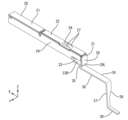
- FIG. 1 is a perspective view of a connector including a terminal fitting according to a first embodiment.
- FIG. 2 is a perspective view of the terminal fitting of the first embodiment.
- FIG. 3 is a side view of the terminal fitting of the first embodiment.
- FIG. 4 is a rear view of the terminal fitting of the first embodiment.
- FIG. 5 is a perspective view of a terminal fitting according to the second embodiment.
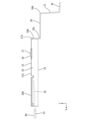
- FIG. 6 is a side view of the terminal fitting of the second embodiment.
- FIG. 7 is a rear view of the terminal fitting of the second embodiment.
- the terminal fitting of the present disclosure is (1) A terminal fitting made of a conductive plate material, comprising: a connection portion having an opening surface at one end in a longitudinal direction; a lead portion extending continuous with the one end side of the connection portion in the longitudinal direction; and a blocking portion blocking the opening surface of the connection portion.
- the blocking portion can prevent foreign matter (objects other than the terminal fittings) from entering the connection portion, thereby maintaining the connection function of the connection portion and ensuring connection reliability.
- the wall portion of the connection portion defines the opening surface at one end in the longitudinal direction, and the blocking portion and the lead portion are shaped to extend from different positions on the wall portion. According to the above configuration (2), the degree of freedom in the shapes of the blocking portion and the lead portion can be increased.
- the lead portion has a bent portion bent from the wall portion to the side opposite the opening surface, and an end of the blocking portion faces the plate surface of the bent portion.
- the bent shape of the lead portion including the bent portion and the minute gap or adhesion structure that can be formed between the end of the blocking portion and the bent portion can more reliably prevent foreign matter from entering the connection portion.
- the blocking portion may be bent from a wall portion of the connection portion to block the opening surface, and the lead portion may be shaped to extend continuously from one end of the blocking portion in the bending direction. According to the above configuration (4), the connecting portion, the blocking portion and the lead portion are continuous, so that the terminal fitting can be easily processed.
- the connector of the present disclosure comprises: (5) A terminal fitting as described in any one of (1) to (4) above, and a housing for holding the terminal fitting, the housing having a pull-out surface from which the lead portion is pulled out, and the blocking portion being exposed and positioned on the pull-out surface.
- the blocking portion can be pressed with a finger, a jig, or the like to accommodate the terminal fitting in the housing.
- the electrical continuity of the terminal fitting can be inspected by applying a probe pin to the blocking portion.
- the blocking portion can have various functions other than the function of preventing foreign matter from entering the connection portion.
- the terminal fitting 20 of the first embodiment is a conductive member provided in a connector 10, as shown in Fig. 1.
- the connector 10 is capable of mating with a mating connector (not shown).
- the front-rear direction refers to the mating direction of the connector 10 with the mating connector.
- the front-rear direction is represented by the symbol X in the figure.
- the left-right direction is represented by the symbol Y in the figure, and the up-down direction is represented by the symbol Z in the figure.
- the left-right direction is synonymous with the width direction, and the up-down direction is synonymous with the height direction.
- the references for these directions are for convenience, and do not necessarily coincide with the references for directions when the connector 10 is mounted on a vehicle (not shown) or the like.
- the terminal fitting 20 is formed by bending a conductive metal plate. As shown in Figs. 2 to 4, the terminal fitting 20 has a tubular connection portion 21 that is elongated in the front-rear direction (length direction). More specifically, the connection portion 21 has a rectangular tubular wall portion. The wall portion is composed of an upper wall 22, a lower wall 23, and a pair of side walls 24. As shown in Fig. 3, an elastically deformable contact portion 25 is disposed within the connection portion 21. A tab 81 of a mating terminal fitting 80 is inserted into the connection portion 21 through a front end opening of the connection portion 21. The tab 81 comes into contact with the contact portion 25 within the connection portion 21, thereby electrically connecting the terminal fitting 20 to the mating terminal fitting 80.
- the terminal fitting 20 has a press-fit portion 26. As shown in FIG. 2, the press-fit portion 26 is formed by bending upward a portion between a pair of slits 27 formed in the upper wall 22. The pair of slits 27 are formed in the upper wall 22 so as to extend parallel to each other in the front-to-rear direction.
- the terminal fitting 20 has a blocking portion 29 that blocks the opening surface 28 at the rear end of the connection portion 21.
- the blocking portion 29 is plate-shaped (lid-shaped) with its plate surface facing the front-rear direction, and is arranged along the front-rear and left-right directions so as to be able to block the opening surface 28.
- the blocking portion 29 is formed by folding a rectangular plate-shaped portion extending rearward from one side wall 24 (the right side wall 24 in Figure 4) from a crease 31 to the other side in the width direction (the left side in Figure 4).
- the blocking portion 29 has a notch 32 at one corner above the fold 31.
- the upper end of the blocking portion 29 is adjacent to the notch 32 in the width direction and is disposed opposite the rear end surface of the top wall 22.
- the other end of the blocking portion 29 in the width direction is disposed opposite the rear end surface of the other side wall 24 (the left side wall 24 in FIG. 4).
- the lower end 29L of the blocking portion 29 extends beyond the opening surface 28 toward the bent portion 35 of the lead portion 34 described below.
- a recess 33 is formed in the other side wall 24.
- the recess 33 penetrates the rear lower end of the other side wall 24 in the wall thickness direction and communicates with the opening surface 28.
- the rear end 23R of the bottom wall 23 is separated from the other side wall 24 by the recess 33.
- the rear end 23R of the bottom wall 23 has a shape that is shifted toward the recess 33 (the other side in the width direction) relative to the other parts of the bottom wall 23.
- the terminal fitting 20 also has a strip-shaped lead portion 34 extending from the lower wall 23 of the connection portion 21.
- the lead portion 34 is shifted overall to the other side in the width direction (left side in FIG. 4) with respect to the connection portion 21 in correspondence with the shift of the rear end portion 23R of the lower wall 23 described above.
- the lead portion 34 has a bent portion 35 that bends downward from the rear end portion 23R of the lower wall 23 on the side opposite the opening surface 28, an extension portion 36 that extends rearward from the lower end of the bent portion 35, a hanging portion 37 that extends downward from the rear end of the extension portion 36, and a board connection portion 38 that extends rearward from the lower end of the hanging portion 37.
- the bent portion 35 and the hanging portion 37 are both arranged with their plate surfaces facing the front-rear direction.
- the extension portion 36 and the board connection portion 38 are both arranged with their plate surfaces facing the up-down direction.
- the bent portion 35, the extension portion 36, and the upper end of the hanging portion 37 are formed with the same width from the rear end portion 23R of the bottom wall 23.
- the upper and lower intermediate portions of the hanging portion 37 have a sloped portion 39 on one side in the width direction, so that the width narrows downward.
- the lower end portion of the hanging portion 37 and the board connection portion 38 are formed with the same width, and are formed narrower than the upper end side of the hanging portion 37 via the sloped portion 39.
- the lower end 29L of the blocking portion 29 covers the upper part of the rear surface of the bent portion 35.
- the lower end 29L of the blocking portion 29 is disposed opposite the rear surface of the bent portion 35.
- the lower end 29L of the blocking portion 29 is in contact with the rear surface of the bent portion 35.
- the connector 10 is exemplified as a connector 10 mounted on a circuit board 100 such as an FPC (flexible printed circuit).
- the connector 10 includes a plurality of terminal fittings 20, 20B, a housing 60 made of synthetic resin that houses the terminal fittings 20, 20B, and a fixing fitting 90 made of metal.
- the housing 60 is made of synthetic resin and has a rectangular block-shaped housing body 61.
- the housing body 61 has a number of cavities 62 extending in the front-rear direction. Each cavity 62 is formed in two levels, one above the other, in the housing body 61.
- the housing 60 also has a pair of protective walls 63 that protrude rearward from both ends in the width direction at the rear end of the housing body 61.
- the fixing brackets 90 are attached to both end faces of the housing body 61 in the width direction.
- the lower end of the fixing brackets 90 is fixed to the circuit board 100 by soldering.
- the housing 60 is fixed to the circuit board 100 via the fixing brackets 90.
- connection portion 21 of the terminal fitting 20 is inserted from the rear into the cavity 62 of the housing body 61.
- the press-fit portion 26 is pressed into the inner wall of the cavity 62.
- the press-fit portion 26 holds the terminal fitting 20 in the housing body 61 in a state where it is prevented from slipping out.
- the lead portion 34 of the terminal fitting 20 is pulled out rearward from the pull-out surface 64, which is the rear surface of the housing body 61.
- the extension portion 36, the hanging portion 37, and the board connection portion 38 are disposed between each protective wall 63.
- the board connection portion 38 of the lead portion 34 is disposed along the surface of the circuit board 100, and is electrically connected by soldering to the conductive portion 110 (pad) of the circuit board 100.
- the terminal fittings 20 shown in Figures 2-4 are housed in the upper cavity 62.
- the terminal fittings 20B (see Figure 1) housed in the lower cavity 62 are shorter than the terminal fittings 20 shown in Figures 2-4, and unlike the terminal fittings 20, the lead portions 34 are shifted to one side in the width direction relative to the connection portion 21. Because the lead portions 34 of the terminal fittings 20, 20B are shifted to opposite sides in the width direction, the conductive portions 110 corresponding to the terminal fittings 20, 20B can be arranged in a zigzag pattern in the front-to-rear direction on the circuit board 100.
- a sealing material P such as a potting material is filled in the space behind the pull-out surface 64 of the housing body 61 and between each protective wall 63 on the circuit board 100. By filling the space with the sealing material P, it is possible to make the connector 10 waterproof and dustproof.
- the opening surface 28 at the rear end of the connection part 21 is blocked by the blocking part 29.
- the bending shape of the lead part 34 can restrict the movement of the sealing material P toward the connection part 21.
- the contact between the bending part 35 and the blocking part 29 can also prevent the sealing material P from passing between the bending part 35 and the blocking part 29.
- the terminal fitting 20 of this embodiment 1 comprises a cylindrical connection portion 21 extending in the front-rear direction (length direction), a lid-shaped blocking portion 29 that blocks the opening surface 28 at the rear end (one end in the length direction) of the connection portion 21, and a strip-shaped lead portion 34 that extends continuously from the rear end of the connection portion 21.
- the blocking portion 29 can prevent the sealing material P from entering the connection portion 21.
- the connection function of the connection portion 21 can be maintained, and the connection reliability of the terminal fitting 20 can be ensured.
- the blocking portion 29 and the lead portion 34 extend continuously from different portions of the wall of the connection portion 21 (one side wall 24 and the bottom wall 23). This configuration allows for greater freedom in the shape of each of the blocking portion 29 and the lead portion 34.
- the lead portion 34 also has a bent portion 35 that bends from one end of the connection portion 21 to the side opposite the side where the opening surface 28 is located, and the end of the blocking portion 29 faces the plate surface of the bent portion 35.
- the bent shape of the lead portion 34 including the bent portion 35 and the contact structure (close contact structure) between the lower end portion 29L of the blocking portion 29 and the bent portion 35 can more reliably prevent the sealing material P from entering the connection portion 21.
- the connector 10 of the first embodiment includes the terminal fittings 20 and a housing 60 that holds the terminal fittings 20.
- the housing 60 has an extraction surface 64 from which the lead portions 34 are extracted, and the blocking portions 29 are arranged to be exposed on the extraction surface 64.
- the blocking portion 29 can, in addition to preventing the sealing material P from penetrating into the connection portion 21, also function as a pushing surface when assembling the terminal fitting 20 into the housing 60, and as an inspection surface when inspecting the electrical continuity.
- the terminal fitting 20A of the second embodiment differs from the terminal fitting 20 of the first embodiment in the peripheral structure of the blocking portion 29A.
- the rest is the same as the first embodiment, and the same reference numerals are used to designate the same or corresponding parts to the first embodiment, and redundant explanations will be omitted.
- the blocking portion 29A is formed by bending a rectangular plate-like portion extending rearward from the upper wall 22 of the connecting portion 21A downward at the crease 31A. Both side widthwise ends of the blocking portion 29A are disposed opposite the rear end faces of the respective side walls 24. Both side walls 24 do not have recesses 33 and are entirely blocked.
- the lower end 29L which is the end of the blocking portion 29A in the bending direction (bending direction), is disposed opposite the rear end face of the bottom wall 23 and further has a portion that protrudes downward beyond the bottom wall 23.
- the lower end 29L of the blocking portion 29A is narrow except for one end on the width direction.
- the lead portion 34A is bent and extends rearward from the lower end 29L of the blocking portion 29A.
- the lead portion 34A has the same width as the lower end 29L, and has a shape shifted to the other side in the width direction relative to the portion of the blocking portion 29A other than the lower end 29L.
- the lead portion 34A has an extension portion 36 extending rearward from the blocking portion 29A, a hanging portion 37 extending downward from the rear end of the extension portion 36, and a board connection portion 38 extending rearward from the lower end of the hanging portion 37.
- the shapes of the extension portion 36, the hanging portion 37, and the board connection portion 38 are the same as those of the first embodiment.
- the blocking portion 29A can prevent the sealing material P from entering the connection portion 21A, and the connection function of the connection portion 21A can be properly maintained.
- the connection portion 21A, the blocking portion 29A, and the lead portion 34A are formed in succession, so that the ease of processing the terminal fitting 20A can be ensured.
- the connecting portion 21, 21A has a cylindrical shape extending in the front-rear direction.
- the cylindrical portion may have any shape that allows an opening surface to be formed at the rear end, and may have, for example, a gutter shape (concave cross section) extending in the front-rear direction.
- the blocking portion 29, 29A is a portion that prevents the sealing material P from entering the connection portion 21, 21A.
- the blocking portion may be a portion that prevents foreign matter other than the sealing material from entering the connection portion.
- the present disclosure is also applicable to a connector structure that is not sealed with a sealing material such as a potting material.
- the circuit board 100 is configured as a flat flexible board such as an FPC, etc.
- the circuit board may be configured as a board having rigidity.
- the lower end 29L of the blocking portion 29 is disposed so as to contact the rear surface of the bent portion 35.
- the lower end of the blocking portion may simply face away from the rear surface of the bent portion.
Landscapes
- Connector Housings Or Holding Contact Members (AREA)
- Coupling Device And Connection With Printed Circuit (AREA)
Priority Applications (1)
| Application Number | Priority Date | Filing Date | Title |
|---|---|---|---|
| CN202480059219.0A CN121889940A (zh) | 2023-09-27 | 2024-09-12 | 端子零件及连接器 |
Applications Claiming Priority (2)
| Application Number | Priority Date | Filing Date | Title |
|---|---|---|---|
| JP2023-165257 | 2023-09-27 | ||
| JP2023165257A JP2025055855A (ja) | 2023-09-27 | 2023-09-27 | 端子金具およびコネクタ |
Publications (1)
| Publication Number | Publication Date |
|---|---|
| WO2025070094A1 true WO2025070094A1 (ja) | 2025-04-03 |
Family
ID=95203163
Family Applications (1)
| Application Number | Title | Priority Date | Filing Date |
|---|---|---|---|
| PCT/JP2024/032694 Pending WO2025070094A1 (ja) | 2023-09-27 | 2024-09-12 | 端子金具およびコネクタ |
Country Status (3)
| Country | Link |
|---|---|
| JP (1) | JP2025055855A (https=) |
| CN (1) | CN121889940A (https=) |
| WO (1) | WO2025070094A1 (https=) |
Citations (3)
| Publication number | Priority date | Publication date | Assignee | Title |
|---|---|---|---|---|
| JP2008171627A (ja) * | 2007-01-10 | 2008-07-24 | Yazaki Corp | 雌型端子金具 |
| JP2020187945A (ja) * | 2019-05-16 | 2020-11-19 | ヒロセ電機株式会社 | コネクタ装置 |
| JP2021093350A (ja) * | 2019-12-06 | 2021-06-17 | イリソ電子工業株式会社 | コネクタ |
-
2023
- 2023-09-27 JP JP2023165257A patent/JP2025055855A/ja active Pending
-
2024
- 2024-09-12 WO PCT/JP2024/032694 patent/WO2025070094A1/ja active Pending
- 2024-09-12 CN CN202480059219.0A patent/CN121889940A/zh active Pending
Patent Citations (3)
| Publication number | Priority date | Publication date | Assignee | Title |
|---|---|---|---|---|
| JP2008171627A (ja) * | 2007-01-10 | 2008-07-24 | Yazaki Corp | 雌型端子金具 |
| JP2020187945A (ja) * | 2019-05-16 | 2020-11-19 | ヒロセ電機株式会社 | コネクタ装置 |
| JP2021093350A (ja) * | 2019-12-06 | 2021-06-17 | イリソ電子工業株式会社 | コネクタ |
Also Published As
| Publication number | Publication date |
|---|---|
| JP2025055855A (ja) | 2025-04-08 |
| CN121889940A (zh) | 2026-04-17 |
Similar Documents
| Publication | Publication Date | Title |
|---|---|---|
| JP7208115B2 (ja) | コネクタ | |
| KR101832599B1 (ko) | 커넥터 | |
| US9190750B2 (en) | Board-to-board connector | |
| JP6807218B2 (ja) | コネクタ | |
| JP4954050B2 (ja) | 端子及びコネクタ | |
| EP1104051B1 (en) | Connector | |
| JP4592462B2 (ja) | 基板接続用コネクタ | |
| JP5043515B2 (ja) | 嵌合検知コネクタ | |
| US9190753B2 (en) | Electrical connector | |
| CN104078804A (zh) | 连接器 | |
| CN115377719A (zh) | 端子、电线连接器及线对板连接器 | |
| JP6815029B2 (ja) | コンタクト、コネクタ部材、コネクタ及び被接続部材 | |
| US6093054A (en) | Connector for connecting a printed circuit board to a flat flexible circuit | |
| JP4022354B2 (ja) | 基板用コネクタおよびコネクタの嵌合検知構造 | |
| WO2025070094A1 (ja) | 端子金具およびコネクタ | |
| US10340620B2 (en) | Multi-contact connector | |
| JP7038172B2 (ja) | コネクタ | |
| JP5650487B2 (ja) | コネクタ | |
| CN111952761B (zh) | 连接器装置 | |
| JP4021397B2 (ja) | 接続端子及び該接続端子を用いるジョイントコネクタ | |
| WO2020050028A1 (ja) | コネクタ | |
| US20070202752A1 (en) | Electrical socket | |
| JP4717733B2 (ja) | 嵌合検知コネクタ | |
| CN113228425A (zh) | 连接器 | |
| JP7637102B2 (ja) | コネクタ装置及び接続端子 |
Legal Events
| Date | Code | Title | Description |
|---|---|---|---|
| 121 | Ep: the epo has been informed by wipo that ep was designated in this application |
Ref document number: 24871889 Country of ref document: EP Kind code of ref document: A1 |