WO2025062853A1 - 表示装置および表示方法 - Google Patents
表示装置および表示方法 Download PDFInfo
- Publication number
- WO2025062853A1 WO2025062853A1 PCT/JP2024/027590 JP2024027590W WO2025062853A1 WO 2025062853 A1 WO2025062853 A1 WO 2025062853A1 JP 2024027590 W JP2024027590 W JP 2024027590W WO 2025062853 A1 WO2025062853 A1 WO 2025062853A1
- Authority
- WO
- WIPO (PCT)
- Prior art keywords
- lens
- excitation light
- curved surface
- concave curved
- focusing position
- Prior art date
- Legal status (The legal status is an assumption and is not a legal conclusion. Google has not performed a legal analysis and makes no representation as to the accuracy of the status listed.)
- Pending
Links
Images




Classifications
-
- G—PHYSICS
- G02—OPTICS
- G02B—OPTICAL ELEMENTS, SYSTEMS OR APPARATUS
- G02B30/00—Optical systems or apparatus for producing three-dimensional [3D] effects, e.g. stereoscopic images
- G02B30/50—Optical systems or apparatus for producing three-dimensional [3D] effects, e.g. stereoscopic images the image being built up from image elements distributed over a three-dimensional [3D] volume, e.g. voxels
-
- G—PHYSICS
- G09—EDUCATION; CRYPTOGRAPHY; DISPLAY; ADVERTISING; SEALS
- G09F—DISPLAYING; ADVERTISING; SIGNS; LABELS OR NAME-PLATES; SEALS
- G09F13/00—Illuminated signs; Luminous advertising
- G09F13/20—Illuminated signs; Luminous advertising with luminescent surfaces or parts
Definitions
- the present invention relates to a display device and a display method.
- the present invention was made in consideration of the above-mentioned circumstances, and aims to provide technology for displaying higher-definition stereoscopic images.
- a display device includes a display body containing a phosphor, a light source that outputs excitation light that excites the phosphor, a first lens and a second lens that focus the excitation light toward a focusing position inside the display body, a first drive mechanism that drives the first lens to change the focusing position, and a second drive mechanism that drives the second lens to reduce aberrations that occur in response to changes in the focusing position.
- a display device includes a display body containing a phosphor and having a concave curved surface, a light source that outputs excitation light that excites the phosphor, a scan mirror that reflects the excitation light toward the concave curved surface, and a mirror drive mechanism that drives the scan mirror to change the incident position of the excitation light on the concave curved surface.
- Another aspect of the present invention is a display method. This method includes the steps of: using a first lens and a second lens to focus excitation light that excites a phosphor toward a focusing position inside a display body that contains the phosphor; driving the first lens to change the focusing position; and driving the second lens to reduce aberrations that occur in response to the change in the focusing position.
- Another aspect of the present invention is a display method.
- This method includes the steps of reflecting excitation light, which excites the phosphor, toward a concave curved surface of a display body containing the phosphor using a scan mirror, and driving the scan mirror to change the incident position of the excitation light on the concave curved surface.
- the present invention makes it possible to display higher-definition stereoscopic images.
- FIG. 1 is a diagram illustrating a schematic configuration of a display device according to a first embodiment.
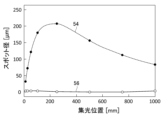
- 11 is a graph showing an example of spherical aberration depending on the focusing position in the example and the comparative example.
- 11 is a graph showing an example of a spot diameter of excitation light depending on a focusing position in an example and a comparative example.
- FIG. 11 is a diagram illustrating a configuration of a display device according to a second embodiment.
- FIG. 13 is a diagram illustrating a configuration of a display device according to a third embodiment.
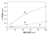
- 11 is a graph showing an example of spherical aberration depending on the focusing position in the example and the comparative example.
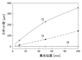
- 11 is a graph showing an example of a spot diameter of excitation light depending on a focusing position in an example and a comparative example.
- First Embodiment 1 is a diagram illustrating a schematic configuration of a display device 10 according to a first embodiment.
- the display device 10 includes a display body 12, an irradiation unit 14, a sensor 16, and a control unit 18.
- the display device 10 is a so-called volume display, and is configured to render a three-dimensional image S inside the display body 12.
- the display 12 includes a phosphor that emits light when irradiated with excitation light 20.
- the phosphor has an excitation wavelength in the ultraviolet light region and an emission wavelength in the visible light region.
- the material of the phosphor is not particularly limited, but may be, for example, a quantum dot phosphor using cesium lead halide perovskite (CsPbX 3 , where X is a halogen and is either Cl, Br, or I, or a mixture of these), or a rare earth phosphor using a rare earth element such as europium (Eu), cerium (Ce), or yttrium (Y).
- the display body 12 comprises, for example, a medium that is transparent to visible light and a phosphor dispersed within the medium.
- the medium may be a solid such as resin or glass, a liquid such as toluene, or a gas. If the medium is a liquid or gas, the display body 12 may comprise a transparent container for containing the medium.
- the transparent container may be made of a resin material or a glass material. Since the display body 12 comprises a transparent solid material, it has a portion that has a higher refractive index than the surroundings of the display body 12 (e.g., air).
- the display body 12 has a first surface 24, a second surface 26, and a side surface 28.
- the first surface 24 is the surface on which the excitation light 20 is incident.
- the second surface 26 is the surface opposite to the surface on which the excitation light 20 is incident.
- the side surface 28 extends from the first surface 24 toward the second surface 26.
- the first surface 24, the second surface 26, and the side surface 28 are made of a material with a higher refractive index than the surroundings (e.g., air), and are made of, for example, a resin material or a glass material.
- the display body 12 is configured to have, for example, a columnar shape, a cylindrical shape, a polygonal prism shape, or a rectangular parallelepiped shape.
- the display body 12 shown in FIG. 1 is cylindrical.
- the display body 12 is configured so that the surfaces of the display body 12 (first surface 24, second surface 26, and side surface 28) are mirror-finished so that the inside of the display body 12 can be seen from the outside.
- the size of the display body 12 is not particularly limited, but for example, the size in the height direction (z direction) from the first surface 24 to the second surface 26 can be about 100 mm to 1000 mm, and the size in the directions perpendicular to the height direction (x direction and y direction) can be about 100 mm to 1000 mm. As an example, the size of the display body 12 in the x, y, and z directions can be 500 mm.
- the irradiation unit 14 irradiates the display body 12 with excitation light 20 for exciting the phosphor contained in the display body 12.
- the excitation light 20 is incident on the first surface 24 of the display body 12 and is focused toward a focusing position 22 inside the display body 12.
- the excitation light 20 is irradiated so that the focusing position 22 inside the display body 12 changes over time.
- the irradiation unit 14 includes a light source 30, a focusing optical system 32, and a scanning optical system 34.
- the light source 30 generates excitation light 20 for exciting the phosphor contained in the display 12.
- the light source 30 generates ultraviolet light having a central wavelength in the range of 300 nm to 400 nm as the excitation light 20.
- GaN gallium nitride
- LED Light Emitting Diode
- the focusing optical system 32 focuses the excitation light 20 generated by the light source 30 toward the inside of the display body 12.
- the focusing optical system 32 changes the focusing position 22 in the irradiation direction of the excitation light 20, and makes the focusing position 22 in the direction intersecting the first surface 24 variable.
- the focusing optical system 32 includes a collimator lens 36, a first lens 38, a second lens 40, a first drive mechanism 42, and a second drive mechanism 44.
- the collimating lens 36 collimates the excitation light 20 generated by the light source 30.
- the first lens 38 focuses the excitation light 20 collimated by the collimating lens 36 toward the inside of the display body 12.
- the first lens 38 is a variable-focus lens, and is driven by a first drive mechanism 42 so that its focal length is variable.
- the second lens 40 corrects aberrations (e.g., spherical aberrations) that occur at the focusing position 22, and reduces the aberrations.
- the second lens 40 is a variable-focus lens, and is driven by a second drive mechanism 44 so that its focal length is variable.
- the positions of the first lens 38 and the second lens 40 on the optical axis are fixed.
- the variable focus lens used as the first lens 38 or the second lens 40 is, for example, a liquid lens, and is configured so that the focal length can be changed by deforming a flexible transparent membrane that seals the liquid lens.
- the shape of the transparent membrane is controlled by changing the pressure applied to the transparent membrane.
- the first drive mechanism 42 or the second drive mechanism 44 is, for example, an electromagnetic actuator or a piezoelectric element that applies pressure to the transparent membrane, and electrically controls the focal length of the variable focus lens by changing the pressure.
- the first lens 38 functions as a focusing lens for focusing parallel light at the focusing position 22.
- the first lens 38 provides a larger positive refractive power than the second lens 40.
- the first lens 38 provides a variable refractive power required to change the focusing position 22 (focal position) of the excitation light 20 over a range from the first surface 24 to the second surface 26, for example.
- the focal length of the first lens 38 is configured to be variable in the range of 200 mm to 700 mm in air equivalent value.
- the second lens 40 functions as an aberration correction lens for reducing the aberration caused by the refraction of the excitation light 20 at the first surface 24. Since the display body 12 has a higher refractive index than the surroundings (e.g., air), the excitation light 20 is refracted at the first surface 24, causing over-spherical aberration at the focusing position 22. The magnitude of this spherical aberration varies depending on the transmission distance (optical path length) of the excitation light 20 inside the display body 12, and the spherical aberration tends to increase as the transmission distance increases. As a result, the amount of aberration correction required varies depending on the focusing position 22 of the excitation light 20.
- the second lens 40 reduces the spherical aberration depending on the focusing position 22 by changing the focal length depending on the focusing position 22. By reducing the aberration at the focusing position 22, the spot diameter of the excitation light 20 at the focusing position 22 can be reduced, and the stereoscopic image S can be drawn with higher resolution.
- the second lens 40 provides a smaller positive refractive power than the first lens 38.
- the focal length of the second lens 40 is configured to be variable over 3000 mm.
- the scanning optical system 34 scans the excitation light 20 that has passed through the focusing optical system 32, and changes the focusing position 22 of the excitation light 20 in the directions along the first surface 24 (x direction and y direction).
- the scanning optical system 34 includes a scanning mirror 46 and a mirror driving mechanism 48.
- the scanning mirror 46 reflects the excitation light 20 toward the first surface 24 of the display body 12.
- the mirror driving mechanism 48 is configured to change the orientation of the scanning mirror 46 in two axes. In the illustrated example, one scanning mirror 46 is used, but a first scanning mirror for scanning in the x direction and a second scanning mirror for scanning in the y direction may be combined.
- the sensor 16 is arranged around the display body 12 and configured to detect the light collection position 22.
- the sensor 16 is, for example, a two-dimensional photodetector such as a CCD sensor or a CMOS sensor, and is a camera that captures an image of the display body 12.
- the sensor 16 is arranged, for example, at a position facing the second surface 26 of the display body 12.
- the position of the sensor 16 is not particularly important, and it may be arranged at a position facing the side surface 28 of the display body 12, or may be arranged at an angle to the display body 12.
- the control unit 18 controls the operation of the irradiation unit 14.
- the control unit 18 may be realized by a combination of hardware and software.
- the hardware of the control unit 18 may be realized by elements or mechanical devices such as a processor such as a CPU (Central Processing Unit) or a GPU (Graphics Processing Unit), and memories such as a ROM (Read Only Memory) or a RAM (Random Access Memory).
- the software of the control unit 18 may be realized by a computer program, etc. In this case, the control unit 18 is depicted as a functional block realized by the cooperation of hardware and software. It will be understood by those skilled in the art that the functional blocks of the control unit 18 can be realized in various ways by a combination of hardware and software.
- the control unit 18 controls the operation of the first drive mechanism 42 and the mirror drive mechanism 48 to control the focusing position 22 of the excitation light 20 in three dimensions (x-direction, y-direction, and z-direction).
- the control unit 18 periodically operates the first drive mechanism 42 and the mirror drive mechanism 48 so that the focusing position 22 of the excitation light 20 is scanned three-dimensionally inside the display body 12.
- the control unit 18 controls the operation of the second drive mechanism 44 to reduce the aberration corresponding to the focusing position 22 of the excitation light 20 and reduce the spot diameter of the excitation light 20 at the focusing position 22.
- the control unit 18 pre-stores table information that associates, for example, the focusing position 22 with the first drive amount of the first drive mechanism 42 and the second drive amount of the second drive mechanism 44, and drives the first drive mechanism 42 and the second drive mechanism 44 according to the table information.
- the control unit 18 may control the operation of at least one of the first drive mechanism 42 and the second drive mechanism 44 based on the detection result of the sensor 16 that detects the focusing position 22.
- the control unit 18 may drive the second drive mechanism 44, for example, so that the spot diameter of the excitation light 20 at the focusing position 22 is minimized.
- the control unit 18 may change the first drive amount in stages, detect the spot diameter of the excitation light 20 for each first drive amount using the sensor 16, and determine the second drive amount at which the spot diameter of the excitation light 20 is minimized.
- the control unit 18 may store the determined combination of the first drive amount and the second drive amount as table information, and drive the first drive mechanism 42 and the second drive mechanism 44 according to the stored table information.
- the control unit 18 controls the on/off of the light source 30 according to the focusing position 22 of the excitation light 20.
- the control unit 18 turns on the light source when the focusing position 22 of the excitation light 20 is a location inside the display body 12 where rendering should be performed.
- the control unit 18 turns off the light source when the focusing position 22 of the excitation light 20 is a location inside the display body 12 where rendering should not be performed.
- the control unit 18 controls the on/off and emission intensity of the light source 30 based on, for example, three-dimensional contour image data generated from the three-dimensional image data.
- the three-dimensional contour image data is data that specifies the three-dimensional position of the contour of the three-dimensional image S to be rendered on the display body 12.
- the control unit 18 acquires the three-dimensional contour image data and operates the irradiation unit 14 based on the three-dimensional contour image data.
- the control unit 18 controls the operation of the first drive mechanism 42, the second drive mechanism 44, and the mirror drive mechanism 48 to three-dimensionally scan the focusing position 22 of the excitation light 20 inside the display body 12 and reduce the aberration according to the focusing position 22.
- the control unit 18 controls the output intensity of the light source 30 according to the focusing position 22 of the excitation light 20, so that the display specified for each drawing position by the three-dimensional contour image data is realized. This allows the three-dimensional image S corresponding to the three-dimensional contour image data to be drawn inside the display body 12.
- the control unit 18 may obtain three-dimensional contour image data corresponding to each frame of the video data, so that a different three-dimensional image S is drawn for each frame. This may allow the three-dimensional image S that becomes the video to be displayed.
- the display method includes the steps of focusing excitation light 20 toward a focusing position 22 inside the display body 12 using a first lens 38 and a second lens 40, driving the first lens 38 to change the focusing position 22, and driving the second lens 40 to reduce aberrations that occur in response to the change in the focusing position 22.
- FIG. 2 is a graph showing an example of spherical aberration according to the focusing position 22 in the examples and comparative examples.
- FIG. 3 is a graph showing an example of the spot diameter of the excitation light 20 according to the focusing position 22 in the examples and comparative examples.
- the examples show a case where a second lens 40 for correcting aberration is provided, and the comparative examples show a case where a second lens 40 for correcting aberration is not provided.
- the wavelength of the excitation light 20 is 405 nm
- the beam diameter of the excitation light 20 collimated by the collimator lens 36 is 200 mm
- the distance along the optical axis from the first lens 38 to the first surface 24 of the display 12 is 260 mm
- the refractive index of the display 12 is 1.51.
- the distance from the first lens 38 to the second lens 40 is 30 mm.
- Figure 2 shows the maximum value of spherical aberration occurring at the focusing position 22.
- the horizontal axis of the graph shows the depth position from the first surface 24 toward the second surface 26 when the position of the first surface 24 of the display body 12 is set to 0 mm.
- the amount of aberration increases as the focusing position 22 becomes deeper. Note that the amount of aberration does not monotonically increase as the focusing position 22 becomes deeper, but shows a tendency to decrease after reaching a maximum at a position where the focusing position 22 is about 300 mm to 400 mm.
- the spherical aberration is proportional to the cube of the numerical aperture (NA) of the excitation light 20, and the deeper focusing position 22 and the smaller NA have an effect of decreasing the amount of aberration.
- NA numerical aperture
- the embodiment shown by the solid line 52 it is possible to keep the amount of aberration to 0.1 mm or less regardless of the focusing position 22, and it can be seen that the aberration can be appropriately reduced. In particular, when the focusing position 22 is within 750 mm, the amount of aberration can be reduced to 0.05 mm or less.
- the spot diameter (RMS, root mean square) of the excitation light 20 at the focusing position 22 shows the spot diameter (RMS, root mean square) of the excitation light 20 at the focusing position 22.
- the horizontal axis of the graph shows the depth position from the first surface 24 toward the second surface 26 of the display body 12 when the position of the first surface 24 of the display body 12 is set to 0 mm.
- the spot diameter increases as the focusing position 22 becomes deeper. Note that the spot diameter does not monotonically increase as the focusing position 22 becomes deeper, but shows a tendency to decrease after reaching a maximum at a position where the focusing position 22 is about 250 mm.
- the focusing position 22 at about 250 mm can be near the center of the display body 12, but if the spot diameter near the center of the display body 12 is about 200 ⁇ m, it becomes difficult to draw the stereoscopic image S with high resolution, and the stereoscopic image S may become blurred and unclear.
- the spot diameter can be made 2 ⁇ m or less, which is close to the diffraction limit, regardless of the focusing position 22. This makes it possible to draw a three-dimensional image S with high resolution, and a clearer three-dimensional image S can be displayed compared to the comparative example.
- Second Embodiment 4 is a diagram showing a schematic configuration of a display device 10A according to a second embodiment.
- the second embodiment differs from the first embodiment in that the first lens 38A is not a variable focus lens but a fixed focus lens that is movable in the optical axis direction 60.
- the second embodiment will be described with a focus on the differences from the first embodiment, and the description of the commonalities will be omitted as appropriate.
- the display device 10A includes a display body 12, an irradiation unit 14A, a sensor 16, and a control unit 18.
- the display body 12, the sensor 16, and the control unit 18 can be configured in the same manner as in the first embodiment described above.
- the irradiation unit 14A includes a light source 30, a focusing optical system 32A, and a scanning optical system 34.
- the light source 30 and the scanning optical system 34 can be configured in the same manner as in the first embodiment described above.
- the focusing optical system 32A includes a collimating lens 36, a first lens 38A, a second lens 40, a first driving mechanism 42A, and a second driving mechanism 44.
- the collimating lens 36, the second lens 40, and the second driving mechanism 44 can be configured in the same manner as in the first embodiment described above.
- the first lens 38A focuses the excitation light 20 collimated by the collimator lens 36 toward the inside of the display body 12.
- the first lens 38A is a fixed-focus lens, and is driven by the first drive mechanism 42A so that its position in the optical axis direction 60 is variable.
- the first drive mechanism 42A is configured to change the position of the first lens 38A in the optical axis direction 60.
- the first drive mechanism 42A changes the position of the first lens 38A to change the focusing position 22 of the excitation light 20.
- the first drive mechanism 42A makes the focusing position 22 in the irradiation direction of the excitation light 20 variable, and makes the focusing position 22 in the direction intersecting the first surface 24 variable.
- the second lens 40 has a fixed position in the optical axis direction 60.
- the second lens 40 is a variable-focus lens, and reduces the spherical aberration according to the focusing position 22 by changing the focal length according to the focusing position 22.
- the control unit 18 controls the operation of the second drive mechanism 44 to reduce the aberration corresponding to the focusing position 22 of the excitation light 20 and reduce the spot diameter of the excitation light 20 at the focusing position 22.
- the control unit 18 pre-stores table information that associates, for example, the focusing position 22 with the first drive amount of the first drive mechanism 42A and the second drive amount of the second drive mechanism 44, and drives the first drive mechanism 42A and the second drive mechanism 44 according to the table information.
- This embodiment also provides the same effects as the first embodiment.
- Third Embodiment 5 is a diagram showing a schematic configuration of a display device 10B according to a third embodiment.
- the third embodiment differs from the first embodiment in that the first surface 24B of the display body 12B is configured to have a concave curved surface 62.
- the third embodiment will be described with a focus on the differences from the first embodiment, and a description of the commonalities will be omitted as appropriate.
- the display device 10B includes a display body 12B, an irradiation unit 14, a sensor 16, and a control unit 18.
- the irradiation unit 14, the sensor 16, and the control unit 18 can be configured in the same manner as in the first embodiment described above.
- the display body 12B has a first surface 24B, a second surface 26, and a side surface 28.
- FIG. 5 shows a cross section of the display body 12B in the xz plane.
- the first surface 24B has a concave curved surface 62 onto which the excitation light 20 is incident.
- the display body 12B can be configured in the same manner as the display body 12 according to the first embodiment, except that the concave curved surface 62 is provided on the first surface 24B.
- the concave curved surface 62 has a shape in which the distance R from the scan mirror 46 is constant, and is configured, for example, to be a sphere centered on the scan mirror 46.
- the excitation light 20 can be made to be perpendicularly incident on the concave curved surface 62.
- the incident position 64 of the excitation light 20 on the concave curved surface 62 changes by driving the scan mirror 46, the excitation light 20 can be made to be perpendicularly incident on the concave curved surface 62 regardless of the change in the incident position 64. This makes it possible to reduce aberrations (for example, astigmatism and coma aberration) that occur when the excitation light 20 is obliquely incident on the first surface of the display body.
- the concave curved surface 62 may have a shape in which the first curvature in the first direction (e.g., x direction) and the second curvature in the second direction (e.g., y direction) are different.
- the first scan mirror scans the excitation light 20 in the first direction (e.g., x direction)
- the radius of curvature of the concave curved surface 62 in the first direction may match the first distance from the first scan mirror to the concave curved surface 62.
- the radius of curvature of the concave curved surface 62 in the second direction may match the second distance from the second scan mirror to the concave curved surface 62.
- the first distance is greater than the second distance, so that the concave curved surface 62 is configured so that the radius of curvature in the first direction is greater than the radius of curvature in the second direction.
- the concave curved surface 62 may be configured to be, for example, an ellipsoidal surface.
- the display method includes the steps of reflecting excitation light 20, which excites the phosphor, toward a concave curved surface 62 of a display body 12B containing the phosphor using a scan mirror 46, and driving the scan mirror 46 to change the incident position 64 of the excitation light 20 on the concave curved surface 62.
- the display method may further include the step of driving the first lens 38 to change the focusing position 22.
- the display method may further include the step of driving the second lens 40 to reduce aberrations that occur in response to the change in the focusing position 22.
- the wavelength of the excitation light 20 is 405 nm
- the beam diameter of the excitation light 20 collimated by the collimator lens 36 is 100 mm
- the refractive index of the display body 12B is 1.51.
- the distance from the scan mirror 46 to the concave curved surface 62 is 100 mm
- the radius of curvature of the concave curved surface 62 is 100 mm.
- the distance from the first lens 38 to the second lens 40 is 30 mm.
- FIG. 6 shows the maximum value of coma aberration occurring at the focusing position 22.
- the horizontal axis of the graph shows the depth position from the first surface 24 or the concave surface 62 of the display body 12B toward the second surface 26, when the position of the first surface 24 or the concave surface 62 is set to 0 mm.
- the amount of aberration increases as the focusing position 22 becomes deeper.
- the second embodiment shown by the dashed line 68 it can be seen that the amount of aberration can be reduced compared to the comparative example.
- the first embodiment shown by the solid line 70 it can be seen that the amount of aberration can be reduced to almost zero (for example, 1 ⁇ m or less) by combining the second lens 40 for correcting the aberration.
- the horizontal axis of the graph shows the depth position from the first surface 24 or the concave curved surface 62 of the display body 12B toward the second surface 26 when the position of the first surface 24 or the concave curved surface 62 is set to 0 mm.
- the spot diameter increases as the focusing position 22 becomes deeper.
- the spot diameter can be reduced compared to the comparative example.
- the display device 10B according to the third embodiment may be configured without the second lens 40 and the second drive mechanism 44, and may be configured similarly to the second embodiment according to Figures 6 and 7.
- the effect of reducing aberration is smaller than in the first embodiment which includes the second lens 40 and the second drive mechanism 44, but compared to the comparative example which does not include the concave curved surface 62, it is possible to reduce aberration and reduce the spot diameter at the focusing position 22. This makes it possible to render the three-dimensional image S with high resolution, and a clearer three-dimensional image S can be displayed compared to the comparative example.
- the display devices 10, 10A, and 10B are shown to have the sensor 16. In other embodiments, the display devices 10, 10A, and 10B may not have the sensor 16. In this case, the display devices 10, 10A, and 10B may operate the first drive mechanism 42, 42A and the second drive mechanism 44 according to table information pre-stored in the control unit 18.
- the table information may include data indicating the first drive amount and the second drive amount according to the focusing position 22.
- a first aspect of the present disclosure includes a display body including a phosphor, a light source that outputs excitation light that excites the phosphor, a first lens and a second lens that focus the excitation light toward a focusing position inside the display body, and a first drive mechanism that drives the first lens to change the focusing position; and a second drive mechanism that drives the second lens to reduce aberration that occurs in accordance with a change in the focusing position.
- the first lens and the second lens may be variable-focus lenses, and the first drive mechanism and the second drive mechanism may change the focal length of the variable-focus lenses.
- the first lens may be a fixed focus lens
- the second lens may be a variable focus lens
- the first drive mechanism may change the position of the fixed focus lens in the optical axis direction
- the second drive mechanism may change the focal length of the variable focus lens
- the device may further include a sensor that detects the focusing position, and a control unit that controls the operation of at least one of the first drive mechanism and the second drive mechanism based on the detection result of the sensor.
- a second aspect of the present disclosure is a display method including the steps of: using a first lens and a second lens to focus excitation light that excites a phosphor toward a focusing position inside a display body that includes the phosphor; driving the first lens to change the focusing position; and driving the second lens to reduce aberrations that occur in response to the change in the focusing position.
- a third aspect of the present disclosure is a display device including a display body having a concave curved surface and including a phosphor, a light source outputting excitation light for exciting the phosphor, a scan mirror that reflects the excitation light toward the concave curved surface, and a mirror drive mechanism that drives the scan mirror to change the incident position of the excitation light on the concave curved surface.
- the concave surface may have a shape that maintains a constant distance from the scan mirror.
- the scan mirror includes a first scan mirror for scanning the excitation light in a first direction and a second scan mirror for scanning the excitation light in a second direction
- the concave curved surface may have a shape in which the first curvature in the first direction and the second curvature in the second direction are different.
- the display may further include a first lens and a second lens that focus the excitation light toward a focusing position inside the display body, a first drive mechanism that drives the first lens to change the focusing position, and a second drive mechanism that drives the second lens to reduce aberrations that occur in response to the change in the focusing position.
- a fourth aspect of the present disclosure is a display method comprising the steps of reflecting excitation light, which excites a phosphor, toward a concave curved surface of a display body containing the phosphor using a scan mirror, and driving the scan mirror to change the incident position of the excitation light on the concave curved surface.
- the present invention makes it possible to display higher-definition stereoscopic images.
Landscapes
- Physics & Mathematics (AREA)
- General Physics & Mathematics (AREA)
- Engineering & Computer Science (AREA)
- Theoretical Computer Science (AREA)
- Optics & Photonics (AREA)
- Lenses (AREA)
Abstract
表示装置(10)は、蛍光体を含む表示体(12)と、蛍光体を励起する励起光(20)を出力する光源(30)と、励起光(20)を表示体(12)の内部の集光位置(22)に向けて集光させる第1レンズ(38)および第2レンズ(40)と、第1レンズ(38)を駆動し、集光位置(22)を変化させる第1駆動機構(42)と、第2レンズ(40)を駆動し、集光位置(22)の変化に応じて生じる収差を低減させる第2駆動機構(44)と、を備える。
Description
本発明は、表示装置および表示方法に関する。
立体画像の表示装置として、蛍光体を含む表示体に紫外光を照射し、紫外光の照射位置を変化させることによって表示体の内部に立体像を描画する構成が提案されている(例えば、特許文献1参照)。
立体画像をより高精細に表示できることが好ましい。
本発明は、上述の事情に鑑みてなされたものであり、より高精細な立体画像を表示する技術を提供することを目的とする。
本発明のある態様の表示装置は、蛍光体を含む表示体と、蛍光体を励起する励起光を出力する光源と、励起光を表示体の内部の集光位置に向けて集光させる第1レンズおよび第2レンズと、第1レンズを駆動し、集光位置を変化させる第1駆動機構と、第2レンズを駆動し、集光位置の変化に応じて生じる収差を低減させる第2駆動機構と、を備える。
本発明の別の態様の表示装置は、蛍光体を含み、凹曲面を有する表示体と、蛍光体を励起する励起光を出力する光源と、励起光を凹曲面に向けて反射させるスキャンミラーと、スキャンミラーを駆動して凹曲面における励起光の入射位置を変化させるミラー駆動機構と、を備える。
本発明のさらに別の態様は、表示方法である。この方法は、蛍光体を含む表示体の内部の集光位置に向けて、蛍光体を励起する励起光を第1レンズおよび第2レンズを用いて集光させるステップと、第1レンズを駆動し、集光位置を変化させるステップと、第2レンズを駆動し、集光位置の変化に応じて生じる収差を低減させるステップと、を備える。
本発明のさらに別の態様は、表示方法である。この方法は、蛍光体を含む表示体の凹曲面に向けて、蛍光体を励起する励起光をスキャンミラーを用いて反射させるステップと、スキャンミラーを駆動し、凹曲面における励起光の入射位置を変化させるステップと、を備える。
なお、以上の構成要素の任意の組み合わせや本発明の構成要素や表現を、方法、装置、システムなどの間で相互に置換したものもまた、本発明の態様として有効である。
本発明によれば、より高精細な立体画像を表示できる。
以下、本発明の実施の形態について、図面を参照しつつ説明する。かかる実施の形態に示す具体的な数値等は、発明の理解を容易とするための例示にすぎず、特に断る場合を除き、本発明を限定するものではない。なお、図面において、本発明に直接関係のない要素は図示を省略する。説明の理解を助けるため、各図面における各構成要素の寸法比は、必ずしも実際の寸法比と一致しない。
(第1実施形態)
図1は、第1実施形態に係る表示装置10の構成を模式的に示す図である。表示装置10は、表示体12と、照射部14と、センサ16と、制御部18とを備える。表示装置10は、いわゆるボリュームディスプレイであり、表示体12の内部に立体像Sを描画するよう構成される。
図1は、第1実施形態に係る表示装置10の構成を模式的に示す図である。表示装置10は、表示体12と、照射部14と、センサ16と、制御部18とを備える。表示装置10は、いわゆるボリュームディスプレイであり、表示体12の内部に立体像Sを描画するよう構成される。
表示体12は、励起光20が照射されることによって発光する蛍光体を含む。蛍光体は、励起波長が紫外光域であり、発光波長が可視光域である。蛍光体の材料は特に限られないが、例えば、ハロゲン化セシウム鉛ペロブスカイト(CsPbX3、Xはハロゲンであり、Cl,Br,Iのいずれか、または、これらの混合)を用いる量子ドット蛍光体や、ユーロピウム(Eu)、セリウム(Ce)、イットリウム(Y)などの希土類元素を用いる希土類蛍光体である。
表示体12は、例えば、可視光に対して透明な媒体と、媒体内に分散される蛍光体とを備える。媒体は、樹脂やガラスなどの固体であってもよいし、トルエンなどの液体であってもよいし、気体であってもよい。媒体が液体または気体である場合、表示体12は、媒体を収容するための透明な容器を備えてもよい。透明な容器は、樹脂材料やガラス材料で構成されてもよい。表示体12は、透明な固体材料を有するため、表示体12の周囲(例えば空気)よりも屈折率が高い部分を有する。
表示体12は、第1面24と、第2面26と、側面28とを備える。第1面24は、励起光20が入射する面である。第2面26は、励起光20が入射する面とは反対側の面である。側面28は、第1面24から第2面26に向けて延びる。第1面24、第2面26および側面28は、周囲(例えば空気)よりも高屈折率の材料で構成され、例えば樹脂材料やガラス材料で構成される。
表示体12は、例えば、柱形状となるように構成され、円柱形状、多角柱形状または直方体形状となるように構成される。図1に示される表示体12は、円柱形状である。表示体12は、表示体12の内部を外から透視できるように表示体12の表面(第1面24、第2面26および側面28)が鏡面仕上げとなるように構成される。
表示体12の大きさは特に限られないが、例えば、第1面24から第2面26に向かう高さ方向(z方向)のサイズを100mm~1000mm程度とし、高さ方向に直交する方向(x方向およびy方向)のサイズを100mm~1000mm程度とすることができる。一例として、表示体12のx,y,z方向のサイズを500mmとすることができる。
照射部14は、表示体12に含まれる蛍光体を励起するための励起光20を表示体12に照射する。励起光20は、表示体12の第1面24に入射し、表示体12の内部の集光位置22に向けて集光される。励起光20は、表示体12の内部の集光位置22が経時的に変化するように照射される。照射部14は、光源30と、集光光学系32と、スキャン光学系34とを備える。
光源30は、表示体12に含まれる蛍光体を励起するための励起光20を生成する。光源30は、例えば、中心波長が300nm~400nmの範囲に含まれる紫外光を励起光20として生成する。光源30の種類は問わないが、例えば、窒化ガリウム(GaN)系の半導体レーザまたは半導体LED(Light Emitting Diode)を光源30として用いることができる。
集光光学系32は、光源30により生成された励起光20を表示体12の内部に向けて集光させる。集光光学系32は、励起光20の照射方向における集光位置22を変化させ、第1面24に交差する方向の集光位置22を可変にする。集光光学系32は、コリメートレンズ36と、第1レンズ38と、第2レンズ40と、第1駆動機構42と、第2駆動機構44とを備える。
コリメートレンズ36は、光源30により生成された励起光20を平行化する。第1レンズ38は、コリメートレンズ36により平行化された励起光20を表示体12の内部に向けて集光させる。第1レンズ38は、焦点可変レンズであり、第1駆動機構42によって焦点距離が可変となるように駆動される。第2レンズ40は、集光位置22にて生じる収差(例えば球面収差)を補正し、収差を低減させる。第2レンズ40は、焦点可変レンズであり、第2駆動機構44によって焦点距離が可変となるように駆動される。第1レンズ38および第2レンズ40の光軸上の位置は固定されている。
第1レンズ38または第2レンズ40として用いられる焦点可変レンズは、例えば、液体レンズで構成され、液体レンズを封止する可撓性の透明膜を変形させることで焦点距離が可変となるよう構成される。透明膜の形状は、透明膜に加える圧力を変化させることで制御される。第1駆動機構42または第2駆動機構44は、例えば、透明膜に圧力を加える電磁アクチュエータや圧電素子であり、圧力を変化させることによって焦点可変レンズの焦点距離を電気的に制御する。
第1レンズ38は、平行光を集光位置22に集光させるための集光レンズとして機能する。第1レンズ38は、第2レンズ40に比べて大きな正の屈折力を提供する。第1レンズ38は、例えば、励起光20の集光位置22(焦点位置)を第1面24から第2面26までの範囲にわたって変化させるために必要となる可変の屈折力を提供する。一例として、第1レンズ38から第1面24までの光軸に沿った距離が200mmであり、第1面24から第2面26までの高さが500mmである場合、第1レンズ38の焦点距離は、空気換算値で200mmから700mmの範囲で可変となるように構成される。
第2レンズ40は、励起光20が第1面24にて屈折することによって生じる収差を低減するための収差補正レンズとして機能する。表示体12は、周囲(例えば空気)よりも高い屈折率を有するため、励起光20が第1面24にて屈折されることによって集光位置22にてオーバーの球面収差が生じる。この球面収差の大きさは、表示体12の内部における励起光20の透過距離(光路長)に応じて変化し、透過距離が大きくなるほど球面収差が大きくなる傾向にある。その結果、励起光20の集光位置22に応じて要求される収差補正量が変化する。第2レンズ40は、集光位置22に応じて焦点距離を変化させることにより、集光位置22に応じた球面収差を低減させる。集光位置22における収差を低減させることにより、集光位置22における励起光20のスポット径を小さくでき、立体像Sをより高精細に描画できる。第2レンズ40は、第1レンズ38に比べて小さな正の屈折力を提供する。上述した一例の場合、第2レンズ40の焦点距離は、3000mm以上で可変となるように構成される。
スキャン光学系34は、集光光学系32を通過した励起光20をスキャンし、励起光20の集光位置22を第1面24に沿った方向(x方向およびy方向)に変化させる。スキャン光学系34は、スキャンミラー46と、ミラー駆動機構48とを備える。スキャンミラー46は、励起光20を表示体12の第1面24に向けて反射させる。ミラー駆動機構48は、スキャンミラー46の向きを2軸で変化させるよう構成される。図示する例では、1枚のスキャンミラー46を用いているが、x方向に走査するための第1スキャンミラーと、y方向に走査するための第2スキャンミラーとを組み合わせてもよい。
センサ16は、表示体12の周囲に配置され、集光位置22を検出するよう構成される。センサ16は、例えば、CCDセンサやCMOSセンサなどの二次元の光検出器であり、表示体12を撮像するカメラである。センサ16は、例えば、表示体12の第2面26と対向する位置に配置される。なお、センサ16の位置は特に問わず、表示体12の側面28と対向する位置に配置されてもよいし、表示体12に対して斜めの向きに配置されてもよい。
制御部18は、照射部14の動作を制御する。制御部18は、ハードウェアとソフトウェアの組み合わせによって実現されてもよい。制御部18のハードウェアは、CPU(Central Processing Unit)やGPU(Graphics Processing Unit)などのプロセッサ、ROM(Read Only Memory)やRAM(Random Access Memory)などのメモリといった素子や機械装置で実現されてもよい。制御部18のソフトウェアは、コンピュータプログラム等によって実現されてもよい。この場合、制御部18は、ハードウェアおよびソフトウェアの連携によって実現される機能ブロックとして描かれる。制御部18の機能ブロックはハードウェア、ソフトウェアの組み合わせによっていろいろなかたちで実現できることは、当業者には理解されるところである。
制御部18は、第1駆動機構42およびミラー駆動機構48の動作を制御することにより、励起光20の集光位置22を三次元(x方向、y方向およびz方向)で制御する。制御部18は、第1駆動機構42およびミラー駆動機構48を周期的に動作させることにより、表示体12の内部において励起光20の集光位置22が三次元走査されるようにする。
制御部18は、第2駆動機構44の動作を制御することにより、励起光20の集光位置22に応じた収差を低減させ、集光位置22における励起光20のスポット径を小さくする。制御部18は、例えば、集光位置22と、第1駆動機構42の第1駆動量と、第2駆動機構44の第2駆動量とを対応付けたテーブル情報を予め記憶し、テーブル情報にしたがって第1駆動機構42および第2駆動機構44を駆動させる。
制御部18は、集光位置22を検出するセンサ16の検出結果に基づいて、第1駆動機構42および第2駆動機構44の少なくとも一方の動作を制御してもよい。制御部18は、例えば、集光位置22における励起光20のスポット径が最小化されるように、第2駆動機構44を駆動させてもよい。制御部18は、第1駆動量を段階的に変化させ、第1駆動量ごとに励起光20のスポット径をセンサ16を用いて検出し、励起光20のスポット径が最小化される第2駆動量を決定してもよい。制御部18は、決定した第1駆動量と第2駆動量の組み合わせをテーブル情報として記憶し、記憶したテーブル情報にしたがって第1駆動機構42および第2駆動機構44を駆動させてもよい。
制御部18は、励起光20の集光位置22に応じて光源30のオンオフを制御する。制御部18は、励起光20の集光位置22が表示体12の内部において描画すべき箇所となる場合に光源をオンにする。制御部18は、励起光20の集光位置22が表示体12の内部において描画すべきではない箇所となる場合に光源をオフにする。制御部18は、例えば、三次元画像データから生成される立体輪郭画像データに基づいて、光源30のオンオフおよび光源30の発光強度を制御する。立体輪郭画像データは、表示体12に描画すべき立体像Sの輪郭の三次元位置が指定されたデータである。
次に、表示装置10の動作について説明する。制御部18は、立体輪郭画像データを取得し、立体輪郭画像データに基づいて照射部14を動作させる。制御部18は、第1駆動機構42、第2駆動機構44およびミラー駆動機構48の動作を制御し、表示体12の内部において励起光20の集光位置22を三次元走査するとともに、集光位置22に応じた収差を低減させる。
制御部18は、励起光20の集光位置22に応じて、光源30の出力強度を制御し、立体輪郭画像データにより描画位置ごとに指定された表示が実現されるようにする。これにより、立体輪郭画像データに対応する立体像Sを表示体12の内部に描画できる。制御部18は、動画データの各フレームに対応する立体輪郭画像データを取得し、フレームごとに異なる立体像Sが描画されるようにしてもよい。これにより、動画となる立体像Sが表示されるようにしてもよい。
本実施形態に係る表示方法は、表示体12の内部の集光位置22に向けて励起光20を第1レンズ38および第2レンズ40を用いて集光させるステップと、第1レンズ38を駆動して集光位置22を変化させるステップと、第2レンズ40を駆動して集光位置22の変化に応じて生じる収差を低減させるステップとを備える。
次に、本実施形態の作用効果について説明する。図2は、実施例および比較例に係る集光位置22に応じた球面収差の一例を示すグラフである。図3は、実施例および比較例に係る集光位置22に応じた励起光20のスポット径の一例を示すグラフである。実施例は、収差を補正するための第2レンズ40が設けられる場合を示し、比較例は、収差を補正するための第2レンズ40が設けられない場合を示す。実施例および比較例では、励起光20の波長を405nmとし、コリメートレンズ36にて平行化された励起光20のビーム径を200mmとし、第1レンズ38から表示体12の第1面24までの光軸に沿った距離を260mmとし、表示体12の屈折率を1.51としている。実施例では、第1レンズ38から第2レンズ40までの距離を30mmとしている。
図2は、集光位置22において発生する球面収差の最大値を示す。グラフの横軸は、表示体12の第1面24の位置を0mmとしたときの、第1面24から第2面26に向かう深さ方向の位置を示す。破線50で示される比較例では、集光位置22が深くなると収差量が大きくなることが分かる。なお、集光位置22が深くなるにつれて収差量が単調に増加するわけではなく、集光位置22が300mm~400mm程度となる位置で極大となった後に低下する傾向を示す。これは、球面収差が励起光20の開口数(NA)の3乗に比例するため、集光位置22が深くなってNAが小さくなることにより、収差量が低下する影響があるためと考えられる。一方、実線52で示される実施例では、集光位置22によらず収差量を0.1mm以下とすることができており、収差を適切に低減できていることが分かる。特に、集光位置22が750mm以下となる範囲では、収差量を0.05mm以下にすることができる。
図3は、集光位置22における励起光20のスポット径(RMS、二乗平均平方根)を示す。グラフの横軸は、図2と同様、表示体12の第1面24の位置を0mmとしたときの、第1面24から第2面26に向かう深さ方向の位置を示す。破線54で示される比較例では、集光位置22が深くなるとスポット径が大きくなることが分かる。なお、集光位置22が深くなるにつれてスポット径が単調に増加するわけではなく、集光位置22が250mm程度となる位置で極大となった後に低下する傾向を示す。250mm程度となる集光位置22は、表示体12の中央付近となりうるが、表示体12の中央付近でのスポット径が200μm程度である場合、立体像Sを高精細に描画することが困難となり、ぼやけた不鮮明な立体像Sとなる可能性がある。一方、実線56で示される実施例では、集光位置22によらずスポット径を回折限界に近い2μm以下とすることができている。これにより、立体像Sを高精細に描画することが可能となり、比較例に比べて鮮明な立体像Sを表示できる。
(第2実施形態)
図4は、第2実施形態に係る表示装置10Aの構成を模式的に示す図である。第2実施系形態は、第1レンズ38Aが焦点可変レンズではなく、光軸方向60に移動可能な焦点固定レンズである点で、上述の第1実施形態と相違する。以下、第2実施形態について、第1実施形態との相違点を中心に説明し、共通点については適宜説明を省略する。
図4は、第2実施形態に係る表示装置10Aの構成を模式的に示す図である。第2実施系形態は、第1レンズ38Aが焦点可変レンズではなく、光軸方向60に移動可能な焦点固定レンズである点で、上述の第1実施形態と相違する。以下、第2実施形態について、第1実施形態との相違点を中心に説明し、共通点については適宜説明を省略する。
表示装置10Aは、表示体12と、照射部14Aと、センサ16と、制御部18とを備える。表示体12、センサ16および制御部18は、上述の第1実施形態と同様に構成されることができる。
照射部14Aは、光源30と、集光光学系32Aと、スキャン光学系34とを備える。光源30およびスキャン光学系34は、上述の第1実施形態と同様に構成されることができる。集光光学系32Aは、コリメートレンズ36と、第1レンズ38Aと、第2レンズ40と、第1駆動機構42Aと、第2駆動機構44とを備える。コリメートレンズ36、第2レンズ40および第2駆動機構44は、上述の第1実施形態と同様に構成されることができる。
第1レンズ38Aは、コリメートレンズ36により平行化された励起光20を表示体12の内部に向けて集光させる。第1レンズ38Aは、焦点固定レンズであり、第1駆動機構42Aによって光軸方向60の位置が可変となるように駆動される。第1駆動機構42Aは、第1レンズ38Aの位置を光軸方向60に変化させるよう構成される。第1駆動機構42Aは、第1レンズ38Aの位置を変化させることにより、励起光20の集光位置22を変化させる。第1駆動機構42Aは、励起光20の照射方向における集光位置22を可変にし、第1面24に交差する方向の集光位置22を可変にする。
第2レンズ40は、第1レンズ38Aとは異なり、光軸方向60の位置が固定されている。第2レンズ40は、焦点可変レンズであり、集光位置22に応じて焦点距離を変化させることにより、集光位置22に応じた球面収差を低減させる。
制御部18は、第2駆動機構44の動作を制御することにより、励起光20の集光位置22に応じた収差を低減させ、集光位置22における励起光20のスポット径を小さくする。制御部18は、例えば、集光位置22と、第1駆動機構42Aの第1駆動量と、第2駆動機構44の第2駆動量とを対応付けたテーブル情報を予め記憶し、テーブル情報にしたがって第1駆動機構42Aおよび第2駆動機構44を駆動させる。
本実施形態においても、第1実施形態と同様の効果を奏することができる。
(第3実施形態)
図5は、第3実施形態に係る表示装置10Bの構成を模式的に示す図である。第3実施形態は、表示体12Bの第1面24Bが凹曲面62を有するように構成される点で、上述の第1実施形態と相違する。以下、第3実施形態について、第1実施形態との相違点を中心に説明し、共通点については適宜説明を省略する。
図5は、第3実施形態に係る表示装置10Bの構成を模式的に示す図である。第3実施形態は、表示体12Bの第1面24Bが凹曲面62を有するように構成される点で、上述の第1実施形態と相違する。以下、第3実施形態について、第1実施形態との相違点を中心に説明し、共通点については適宜説明を省略する。
表示装置10Bは、表示体12Bと、照射部14と、センサ16と、制御部18とを備える。照射部14、センサ16および制御部18は、上述の第1実施形態と同様に構成されることができる。
表示体12Bは、第1面24Bと、第2面26と、側面28とを備える。図5は、xz平面における表示体12Bの断面を示す。第1面24Bは、励起光20が入射する凹曲面62を有する。表示体12Bは、第1面24Bに凹曲面62が設けられる点を除いて、第1実施形態に係る表示体12と同様に構成されることができる。
凹曲面62は、スキャンミラー46からの距離Rが一定となる形状を有し、例えばスキャンミラー46を中心とする球面となるように構成される。その結果、励起光20の照射方向がz方向から傾斜している場合であっても、励起光20を凹曲面62に垂直に入射させることができる。すなわち、スキャンミラー46を駆動して凹曲面62における励起光20の入射位置64が変化したとしても、励起光20は、入射位置64の変化に依らずに凹曲面62に垂直に入射できる。これにより、励起光20が表示体の第1面に斜めに入射することによって発生する収差(例えば非点収差やコマ収差)を低減できる。
凹曲面62は、例えば、スキャンミラー46が第1スキャンミラーおよび第2スキャンミラーを備える場合、第1方向(例えばx方向)の第1曲率と、第2方向(例えばy方向)第2曲率とが異なる形状を有してもよい。例えば、第1スキャンミラーが第1方向(例えばx方向)に励起光20をスキャンする場合、凹曲面62の第1方向の曲率半径は、第1スキャンミラーから凹曲面62までの第1距離に一致してもよい。第2スキャンミラーが第2方向(例えばy方向)に励起光20をスキャンする場合、凹曲面62の第2方向の曲率半径は、第2スキャンミラーから凹曲面62までの第2距離に一致してもよい。励起光20が第1スキャンミラーで反射した後に第2スキャンミラーで反射されてから凹曲面62に入射する場合、第1距離が第2距離よりも大きいため、凹曲面62は、第1方向の曲率半径が第2方向の曲率半径よりも大きくなるように構成される。凹曲面62は、例えば楕円球面となるように構成されてもよい。これにより、第1スキャンミラーおよび第2スキャンミラーを駆動して凹曲面62における励起光20の入射位置64を変化したとしても、励起光20は、入射位置64の変化に依らず凹曲面62に垂直に入射できる。
本実施形態に係る表示方法は、蛍光体を含む表示体12Bの凹曲面62に向けて、蛍光体を励起する励起光20をスキャンミラー46を用いて反射させるステップと、スキャンミラー46を駆動し、凹曲面62における励起光20の入射位置64を変化させるステップと、を備える。表示方法は、第1レンズ38を駆動して集光位置22を変化させるステップをさらに備えてもよい。表示方法は、第2レンズ40を駆動して集光位置22の変化に応じて生じる収差を低減させるステップをさらに備えてもよい。
次に、本実施形態の作用効果について説明する。図6は、実施例および比較例に係る集光位置22に応じたコマ収差の一例を示すグラフである。図7は、実施例および比較例に係る集光位置22に応じた励起光20のスポット径の一例を示すグラフである。実線70,76で示される第1実施例は、表示体12Bの第1面24Bに凹曲面62が設けられ、収差を補正するための第2レンズ40が設けられる場合を示す。一点鎖線68,74で示される第2実施例は、表示体12Bの第1面24Bに凹曲面62が設けられる一方で、収差を補正するための第2レンズ40が設けられない場合を示す。破線66,72で示される比較例は、第1実施形態に係る比較例と同様に、表示体12の第1面24が平坦面であり、収差を補正するための第2レンズ40が設けられない場合を示す。
第1実施例、第2実施例および比較例では、励起光20の波長を405nmとし、コリメートレンズ36にて平行化された励起光20のビーム径を100mmとし、表示体12Bの屈折率を1.51としている。第1実施例および第2実施例では、スキャンミラー46から凹曲面62までの距離を100mmとし、凹曲面62の曲率半径を100mmとしている。第1実施例では、第1レンズ38から第2レンズ40までの距離を30mmとしている。
図6は、集光位置22において発生するコマ収差の最大値を示す。グラフの横軸は、表示体12Bの第1面24または凹曲面62の位置を0mmとしたときの、第1面24または凹曲面62から第2面26に向かう深さ方向の位置を示す。破線66で示される比較例では、集光位置22が深くなると収差量が大きくなることが分かる。一点鎖線68で示される第2実施例では、比較例に比べて収差量を低減できていることが分かる。実線70で示される第1実施例では、収差を補正するための第2レンズ40を組み合わせることにより、収差量をほぼゼロ(例えば1μm以下)に低減できていることが分かる。
図7は、集光位置22における励起光20のスポット径(RMS、二乗平均平方根)を示す。グラフの横軸は、図6と同様、表示体12Bの第1面24または凹曲面62の位置を0mmとしたときの、第1面24または凹曲面62から第2面26に向かう深さ方向の位置を示す。破線72で示される比較例では、集光位置22が深くなるとスポット径が大きくなることが分かる。一点破線74で示される第2実施例では、比較例に比べてスポット径を低減できていることが分かる。実線76で示される第1実施例では、集光位置22によらずスポット径を回折限界に近い2μm以下とすることができている。これにより、立体像Sを高精細に描画することが可能となり、比較例に比べて鮮明な立体像Sを表示できる。
第3実施形態に係る表示装置10Bは、第1実施形態に係る照射部14の代わりに、第2実施形態に係る照射部14Aを備えてもよい。すなわち、表示装置10Bは、第1レンズ38Aの位置を光軸方向60に変化させることにより、集光位置22の深さ位置を変化させてもよい。
第3実施形態に係る表示装置10Bは、第2レンズ40および第2駆動機構44を備えない構成としてもよく、図6および図7に係る第2実施例と同様に構成してもよい。第2実施例の場合、第2レンズ40および第2駆動機構44を備える第1実施例に比べて、収差を低減する効果が小さくなるが、凹曲面62を備えない比較例に比べて、収差を低減することができ、集光位置22でのスポット径を小さくできる。これにより、立体像Sを高精細に描画することが可能となり、比較例に比べて鮮明な立体像Sを表示できる。
上述の実施形態では、表示装置10,10A,10Bがセンサ16を備える場合について示した。他の実施形態では、表示装置10,10A,10Bがセンサ16を備えなくてもよい。この場合、表示装置10,10A,10Bは、制御部18に予め記憶されるテーブル情報にしたがって、第1駆動機構42,42Aおよび第2駆動機構44を動作させてもよい。テーブル情報は、集光位置22に応じた第1駆動量および第2駆動量を示すデータを含んでもよい。
以上、本発明を上述の実施の形態を参照して説明したが、本発明は上述の実施の形態に限定されるものではなく、各表示例に示す構成を適宜組み合わせたものや置換したものについても本発明に含まれるものである。
以下、本開示のいくつかの態様について述べる。
本開示の第1の態様は、蛍光体を含む表示体と、前記蛍光体を励起する励起光を出力する光源と、前記励起光を前記表示体の内部の集光位置に向けて集光させる第1レンズおよび第2レンズと、前記第1レンズを駆動し、前記集光位置を変化させる第1駆動機構と、
前記第2レンズを駆動し、前記集光位置の変化に応じて生じる収差を低減させる第2駆動機構と、を備える表示装置である。
前記第2レンズを駆動し、前記集光位置の変化に応じて生じる収差を低減させる第2駆動機構と、を備える表示装置である。
第1の態様において、前記第1レンズおよび前記第2レンズは、焦点可変レンズであり、前記第1駆動機構および前記第2駆動機構は、前記焦点可変レンズの焦点距離を変化させてもよい。
第1の態様において、前記第1レンズは、焦点固定レンズであり、前記第2レンズは、焦点可変レンズであり、前記第1駆動機構は、前記焦点固定レンズの光軸方向の位置を変化させ、前記第2駆動機構は、前記焦点可変レンズの焦点距離を変化させてもよい。
第1の態様において、前記集光位置を検出するセンサと、前記センサの検出結果に基づいて、前記第1駆動機構および前記第2駆動機構の少なくとも一方の動作を制御する制御部と、をさらに備えてもよい。
本開示の第2の態様は、蛍光体を含む表示体の内部の集光位置に向けて、前記蛍光体を励起する励起光を第1レンズおよび第2レンズを用いて集光させるステップと、前記第1レンズを駆動し、前記集光位置を変化させるステップと、前記第2レンズを駆動し、前記集光位置の変化に応じて生じる収差を低減させるステップと、を備える表示方法である。
本開示の第3の態様は、蛍光体を含み、凹曲面を有する表示体と、前記蛍光体を励起する励起光を出力する光源と、前記励起光を前記凹曲面に向けて反射させるスキャンミラーと、前記スキャンミラーを駆動して前記凹曲面における前記励起光の入射位置を変化させるミラー駆動機構と、を備える表示装置である。
第3の態様において、前記凹曲面は、前記スキャンミラーからの距離が一定となる形状を有してもよい。
第3の態様において、前記スキャンミラーは、前記励起光を第1方向にスキャンするための第1スキャンミラーと、前記励起光を第2方向にスキャンするための第2スキャンミラーとを備え、前記凹曲面は、前記第1方向の第1曲率と前記第2方向の第2曲率とが異なる形状を有してもよい。
第3の態様において、前記励起光を前記表示体の内部の集光位置に向けて集光させる第1レンズおよび第2レンズと、前記第1レンズを駆動し、前記集光位置を変化させる第1駆動機構と、前記第2レンズを駆動し、前記集光位置の変化に応じて生じる収差を低減させる第2駆動機構と、をさらに備えてもよい。
本開示の第4の態様は、蛍光体を含む表示体の凹曲面に向けて、前記蛍光体を励起する励起光をスキャンミラーを用いて反射させるステップと、前記スキャンミラーを駆動し、前記凹曲面における前記励起光の入射位置を変化させるステップと、を備える表示方法である。
本発明によれば、より高精細な立体画像を表示できる。
10,10A,10B…表示装置、12,12B…表示体、14,14A…照射部、16…センサ、18…制御部、20…励起光、22…集光位置、30…光源、32,32A…集光光学系、34…スキャン光学系、36…コリメートレンズ、38,38A…第1レンズ、40…第2レンズ、42,42A…第1駆動機構、44…第2駆動機構、46…スキャンミラー、48…ミラー駆動機構、62…凹曲面。
Claims (10)
- 蛍光体を含む表示体と、
前記蛍光体を励起する励起光を出力する光源と、
前記励起光を前記表示体の内部の集光位置に向けて集光させる第1レンズおよび第2レンズと、
前記第1レンズを駆動し、前記集光位置を変化させる第1駆動機構と、
前記第2レンズを駆動し、前記集光位置の変化に応じて生じる収差を低減させる第2駆動機構と、を備える、
表示装置。 - 前記第1レンズおよび前記第2レンズは、焦点可変レンズであり、
前記第1駆動機構および前記第2駆動機構は、前記焦点可変レンズの焦点距離を変化させる、
請求項1に記載の表示装置。 - 前記第1レンズは、焦点固定レンズであり、
前記第2レンズは、焦点可変レンズであり、
前記第1駆動機構は、前記焦点固定レンズの光軸方向の位置を変化させ、
前記第2駆動機構は、前記焦点可変レンズの焦点距離を変化させる、
請求項1に記載の表示装置。 - 前記集光位置を検出するセンサと、
前記センサの検出結果に基づいて、前記第1駆動機構および前記第2駆動機構の少なくとも一方の動作を制御する制御部と、をさらに備える、
請求項1から3のいずれか一項に記載の表示装置。 - 前記表示体は、前記励起光が入射する凹曲面を有し、
前記励起光を前記凹曲面に向けて反射させるスキャンミラーと、
前記スキャンミラーを駆動して前記凹曲面における前記励起光の入射位置を変化させるミラー駆動機構と、をさらに備える、
請求項1から4のいずれか一項に記載の表示装置。 - 蛍光体を含み、凹曲面を有する表示体と、
前記蛍光体を励起する励起光を出力する光源と、
前記励起光を前記凹曲面に向けて反射させるスキャンミラーと、
前記スキャンミラーを駆動して前記凹曲面における前記励起光の入射位置を変化させるミラー駆動機構と、を備える、
表示装置。 - 前記凹曲面は、前記スキャンミラーからの距離が一定となる形状を有する、
請求項5または6に記載の表示装置。 - 前記スキャンミラーは、前記励起光を第1方向にスキャンするための第1スキャンミラーと、前記励起光を第2方向にスキャンするための第2スキャンミラーとを備え、
前記凹曲面は、前記第1方向の第1曲率と前記第2方向の第2曲率とが異なる形状を有する、
請求項5から7のいずれか一項に記載の表示装置。 - 蛍光体を含む表示体の内部の集光位置に向けて、前記蛍光体を励起する励起光を第1レンズおよび第2レンズを用いて集光させるステップと、
前記第1レンズを駆動し、前記集光位置を変化させるステップと、
前記第2レンズを駆動し、前記集光位置の変化に応じて生じる収差を低減させるステップと、を備える、
表示方法。 - 蛍光体を含む表示体の凹曲面に向けて、前記蛍光体を励起する励起光をスキャンミラーを用いて反射させるステップと、
前記スキャンミラーを駆動し、前記凹曲面における前記励起光の入射位置を変化させるステップと、を備える、
表示方法。
Applications Claiming Priority (4)
| Application Number | Priority Date | Filing Date | Title |
|---|---|---|---|
| JP2023-158145 | 2023-09-22 | ||
| JP2023158144A JP2025049762A (ja) | 2023-09-22 | 2023-09-22 | 表示装置および表示方法 |
| JP2023158145A JP2025049763A (ja) | 2023-09-22 | 2023-09-22 | 表示装置および表示方法 |
| JP2023-158144 | 2023-09-22 |
Publications (1)
| Publication Number | Publication Date |
|---|---|
| WO2025062853A1 true WO2025062853A1 (ja) | 2025-03-27 |
Family
ID=95072717
Family Applications (1)
| Application Number | Title | Priority Date | Filing Date |
|---|---|---|---|
| PCT/JP2024/027590 Pending WO2025062853A1 (ja) | 2023-09-22 | 2024-08-01 | 表示装置および表示方法 |
Country Status (1)
| Country | Link |
|---|---|
| WO (1) | WO2025062853A1 (ja) |
Citations (5)
| Publication number | Priority date | Publication date | Assignee | Title |
|---|---|---|---|---|
| US6466184B1 (en) * | 1998-12-29 | 2002-10-15 | The United States Of America As Represented By The Secretary Of The Navy | Three dimensional volumetric display |
| JP2010211842A (ja) * | 2009-03-09 | 2010-09-24 | Hitachi Media Electoronics Co Ltd | 光ピックアップ、光学的情報再生装置および光学的情報記録再生装置 |
| WO2020218035A1 (ja) * | 2019-04-26 | 2020-10-29 | パナソニックIpマネジメント株式会社 | 光学系 |
| CN113433715A (zh) * | 2021-06-23 | 2021-09-24 | 上海先研光电科技有限公司 | 光电双调制的三维显示方法、显示元件和三维显示装置 |
| JP2023095147A (ja) * | 2021-12-24 | 2023-07-06 | 株式会社Jvcケンウッド | 表示装置 |
-
2024
- 2024-08-01 WO PCT/JP2024/027590 patent/WO2025062853A1/ja active Pending
Patent Citations (5)
| Publication number | Priority date | Publication date | Assignee | Title |
|---|---|---|---|---|
| US6466184B1 (en) * | 1998-12-29 | 2002-10-15 | The United States Of America As Represented By The Secretary Of The Navy | Three dimensional volumetric display |
| JP2010211842A (ja) * | 2009-03-09 | 2010-09-24 | Hitachi Media Electoronics Co Ltd | 光ピックアップ、光学的情報再生装置および光学的情報記録再生装置 |
| WO2020218035A1 (ja) * | 2019-04-26 | 2020-10-29 | パナソニックIpマネジメント株式会社 | 光学系 |
| CN113433715A (zh) * | 2021-06-23 | 2021-09-24 | 上海先研光电科技有限公司 | 光电双调制的三维显示方法、显示元件和三维显示装置 |
| JP2023095147A (ja) * | 2021-12-24 | 2023-07-06 | 株式会社Jvcケンウッド | 表示装置 |
Similar Documents
| Publication | Publication Date | Title |
|---|---|---|
| CN109477954A (zh) | 具有相位调制元件的scape显微术和图像重构 | |
| CN104977715A (zh) | 利用光栅多边形在成像表面上进行2d直线扫描 | |
| JP2007528020A (ja) | 投影装置 | |
| KR20130136394A (ko) | 화상 표시 장치 및 헤드 마운트 디스플레이 | |
| JP6423841B2 (ja) | 試料観察装置及び試料観察方法 | |
| JPWO2018066062A1 (ja) | 投影光学系、及びヘッドアップディスプレイ装置 | |
| KR20130136392A (ko) | 화상 표시 장치 및 헤드 마운트 디스플레이 | |
| JP7375471B2 (ja) | 可動装置、画像投影装置、ヘッドアップディスプレイ、レーザヘッドランプ、ヘッドマウントディスプレイ、物体認識装置、及び車両 | |
| WO2024203893A1 (ja) | 立体表示装置及び立体表示方法 | |
| US11852792B2 (en) | Sample observation device | |
| US9384380B2 (en) | Information recording media, information reproduction apparatus, and information reproducing method | |
| JP6616005B2 (ja) | 投影光学系およびヘッドアップディスプレイ装置 | |
| WO2025062853A1 (ja) | 表示装置および表示方法 | |
| JP2025049763A (ja) | 表示装置および表示方法 | |
| JP2025049762A (ja) | 表示装置および表示方法 | |
| JP5929204B2 (ja) | 走査型顕微鏡 | |
| KR101539425B1 (ko) | 고스트 이미지가 제거된 영상 획득이 가능한 3차원 스캐너 | |
| CN107209359B (zh) | 图像取得装置以及图像取得方法 | |
| JP2007094079A (ja) | 光学装置及び走査型顕微鏡 | |
| JP6326813B2 (ja) | 画像表示装置 | |
| WO2019181300A1 (ja) | 走査光学装置 | |
| CN113302514B (zh) | 用于分区飞行时间成像的照明 | |
| JP7329113B2 (ja) | 試料観察装置 | |
| JP6326814B2 (ja) | 投射光学系 | |
| JP2008026643A (ja) | レーザ走査型顕微鏡 |
Legal Events
| Date | Code | Title | Description |
|---|---|---|---|
| 121 | Ep: the epo has been informed by wipo that ep was designated in this application |
Ref document number: 24867934 Country of ref document: EP Kind code of ref document: A1 |