WO2025057823A1 - ばね部材 - Google Patents
ばね部材 Download PDFInfo
- Publication number
- WO2025057823A1 WO2025057823A1 PCT/JP2024/031663 JP2024031663W WO2025057823A1 WO 2025057823 A1 WO2025057823 A1 WO 2025057823A1 JP 2024031663 W JP2024031663 W JP 2024031663W WO 2025057823 A1 WO2025057823 A1 WO 2025057823A1
- Authority
- WO
- WIPO (PCT)
- Prior art keywords
- coil spring
- adhesive
- insulator
- sheet
- spring
- Prior art date
- Legal status (The legal status is an assumption and is not a legal conclusion. Google has not performed a legal analysis and makes no representation as to the accuracy of the status listed.)
- Pending
Links
Images



Classifications
-
- F—MECHANICAL ENGINEERING; LIGHTING; HEATING; WEAPONS; BLASTING
- F16—ENGINEERING ELEMENTS AND UNITS; GENERAL MEASURES FOR PRODUCING AND MAINTAINING EFFECTIVE FUNCTIONING OF MACHINES OR INSTALLATIONS; THERMAL INSULATION IN GENERAL
- F16F—SPRINGS; SHOCK-ABSORBERS; MEANS FOR DAMPING VIBRATION
- F16F1/00—Springs
- F16F1/02—Springs made of steel or other material having low internal friction; Wound, torsion, leaf, cup, ring or the like springs, the material of the spring not being relevant
- F16F1/04—Wound springs
- F16F1/12—Attachments or mountings
Definitions
- the present invention relates to a spring member.
- a spring member that includes a coil spring made of wire wound in a spiral shape and a seat portion that is provided at the end of the coil spring and receives the load of the coil spring (see, for example, Patent Document 1).
- an elastic insulator is disposed between the coil spring and the seat portion, and the coil spring and the insulator are fixed together with an adhesive.
- spring components are required to be durable against high loads.
- the spring member of the present invention comprises a coil spring made of wire wound in a spiral shape, and a sheet portion provided at one end of the coil spring and receiving the load of the coil spring, the sheet portion having a sheet covering a part of one end of the coil spring, an insulator provided between the sheet and the coil spring, and an adhesive for bonding the insulator and the coil spring, and characterized in that in the sheet portion, the end of the adhesive on the one end side of the coil spring is positioned at the edge of the coil spring or on the other end side of the edge.
- the spring member according to the present invention is characterized in that, in the above invention, in the sheet portion, the ends of the insulator and the adhesive on one end side of the coil spring are positioned at the edge of the coil spring, or on the other end side of the edge.
- the spring member according to the present invention is characterized in that the ends of the insulator and the adhesive on one end side of the coil spring are each located within a range of 0.1000 turns from the edge end with respect to the end face of the coil spring.
- the spring member according to the present invention is characterized in that the adhesive is positioned such that the end of one end of the coil spring is located within 0.0125 turns from the edge of the coil spring with respect to the end face of the coil spring.
- the present invention has the effect of providing a spring member that can improve durability against load.
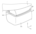
- FIG. 1 is a diagram showing a configuration of a spring member according to an embodiment of the present invention.
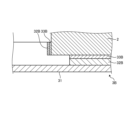
- FIG. 2 is an enlarged view of a portion of the spring member shown in FIG.
- FIG. 3 is a diagram for explaining the configuration of a conventional spring member that serves as a reference.
- FIG. 4 is a diagram for explaining a cutting method for the insulator in the analysis.
- FIG. 5 is a diagram (part 1) showing an example in which a part of an insulator is cut away in a spring member.
- FIG. 6 is a diagram (part 2) showing an example in which a part of the insulator is cut away in the spring member.
- FIG. 7 is a diagram for explaining the analysis results of the spring member according to the embodiment of the present invention.
- FIG. 1 is a diagram showing a configuration of a spring member according to an embodiment of the present invention.
- FIG. 2 is an enlarged view of a portion of the spring member shown in FIG.
- FIG. 3 is a diagram for explaining the configuration of
- FIG. 8 is an enlarged view of a part of a spring member according to the first modification of the embodiment of the present invention.
- FIG. 9 is a diagram for explaining an analysis result of the spring member according to the first modification.
- FIG. 10 is a cross-sectional view showing a configuration of a portion of a spring member according to the second modification of the embodiment of the present invention.
- Fig. 1 is a diagram showing the configuration of a spring member according to an embodiment of the present invention.
- Fig. 2 is an enlarged view of a portion of the spring member shown in Fig. 1.
- the spring member 1 includes a coil spring 2 formed by winding a wire in a spiral shape, and a seat portion 3 provided at an end of the coil spring 2 and receiving the load of the coil spring.
- the coil spring 2 is formed, for example, using flat spring steel made of metal, resin, etc.
- the wire is wound around an axis extending in the Z direction shown in FIG. 1.
- the side of the coil spring 2 on which the sheet portion 3 is disposed is referred to as the base end side (one end side)
- the side opposite the side on which the sheet portion 3 is disposed is referred to as the tip side (other end side)
- a load is applied to the coil spring 2 that presses the tip side (other end side) towards the base end side (one end side).
- the sheet 31 is concave and covers a part of the base end of the coil spring 2.
- the sheet 31 has a length less than one turn of the coil spring 2 and covers the base end of the coil spring 2. Specifically, the sheet 31 covers a part of the side surface of the base end of the coil spring 2 and exposes the end face (the surface intersecting the longitudinal (extension) direction of the wire). Therefore, the coil spring 2 can be displaced in the extension direction (Y direction shown in FIG. 2) by elastic deformation of the adhesive 33, etc.
- One turn here corresponds to one revolution of the wire of the coil spring 2 around the winding axis.
- the end of the coil spring 2 on the sheet part 3 side (end on the base end side) is taken as the base point (0th turn), and the winding position around the winding axis is expressed as the "turn".
- the first turn is the position equivalent to the above-mentioned one revolution from the base point.
- the insulator 32 is made of an elastic material, such as rubber, and is disposed between the sheet 31 and the coil spring 2 in the region where the sheet 31 is disposed.
- the adhesive 33 is, for example, a resin.
- the end positions of the insulator 32 and adhesive 33 on the base end side of the coil spring 2 include the edge of the coil spring 2, and are located closer to the wire side than the edge.
- the edge here corresponds to the outer edge that forms the end face of the coil spring 2.
- the insulator 320 is made of an elastic material, such as rubber, and is disposed between the sheet 310 and the coil spring 2 in the region where the sheet 310 is disposed.
- the adhesive 330 is, for example, a resin.
- the insulator 320 and the adhesive 330 cover a portion of the side surface and a portion of the end surface of the coil spring 2 . Therefore, the movement of the coil spring 2 in the extension direction (Y direction in FIG. 3 ) is restricted by the seat portion 300 .
- a model of the above-mentioned comparison standard spring component was created and the shear stress was calculated.
- FIG 4 is a diagram for explaining the cutting method for the insulator in the analysis.
- the shear stress was analyzed for each insulator 32 in which a portion was cut at each dashed line, such as the insulator 32 shown in Figure 4.
- the adhesive 33 is also cut in the same way. This cut moves the position of the end of the insulator 32 and adhesive 33 on the end side of the coil spring 2 from the base end of the coil spring 2 to the tip side of the coil spring 2 (the side along the wire).
- FIGS 5 and 6 are diagrams showing an example of a spring member in which part of the insulator has been cut.
- the model 110 shown in FIG. 5 includes a coil spring 120 corresponding to the coil spring 2 and a seat portion 130A corresponding to the seat portion 3.
- the sheet portion 130A has a sheet 131 corresponding to the sheet 31, an insulator 132A corresponding to the insulator 32, and an adhesive 133A corresponding to the adhesive 33.
- a model 111 shown in FIG. 6 includes a coil spring 120 corresponding to the coil spring 2 and a seat portion 130B corresponding to the seat portion 3.
- the sheet portion 130B has a sheet 131 corresponding to the sheet 31, an insulator 132B corresponding to the insulator 32, and an adhesive 133B corresponding to the adhesive 33.
- the shear stress was calculated for a flush model (see Figures 1 and 2), a model with 0.0375 turns cut, a model with 0.0750 turns cut, and a model with 0.1125 turns cut.
- Figure 7 is a diagram for explaining the analysis results, showing the results of analyzing models in which the insulator and adhesive have been cut.
- sample A is a flush model (see Figure 2)
- sample B is a model in which 0.0375 turns have been cut (see Figure 6)
- sample C is a model in which 0.0750 turns have been cut (see Figure 5)
- sample D is a model in which 0.1125 turns have been cut
- the standard is a model of a comparative standard spring member (see Figure 3), and the ratio of shear stress to the standard is shown.
- the shear stress of each of the samples A to C is reduced relative to the reference.
- the analysis results showed that the shear stress of the flush model was the lowest, and the shear stress increased as the number of turns to be cut increased.
- the result was that the shear stress was higher than the standard. This is thought to be because when the mass (adhesive area) of the adhesive 33 etc. is reduced, the area over which the adhesive 33 receives the load from the coil spring 2 is reduced, and the shear stress increases.
- the ends of the insulator 32 and adhesive 33 on the base end side of the coil spring 2 are positioned at the edge of the coil spring 2 or on the other end side of the edge, specifically in a range from flush with the base end face of the coil spring 2 (0th turn) to 0.1000th turn.
- this embodiment by making the end positions of the insulator 32 and adhesive 33 satisfy the above-described conditions, when a load is applied to the coil spring 2 toward the sheet portion 3, damage caused by the edge of the coil spring 2 biting into the adhesive 33 or insulator 32 can be suppressed, and as a result, a spring member with improved durability against load can be obtained.
- the amount of insulator 32 and adhesive 33 used can be reduced compared to the conventional method, making the spring member 1 lighter than the conventional method.
- the above-mentioned configuration makes it possible to increase the natural frequency compared to the conventional case, and as a result, damage to the spring member 1 can be further suppressed.
- Fig. 8 is an enlarged view of a part of the spring member according to the first modified example.
- a configuration in which only the adhesive is cut out in the above-mentioned spring member will be described. Note that the same components as those in the above-mentioned embodiment are given the same reference numerals.
- the spring member in this variation 1 comprises a coil spring 2 made of wire wound in a spiral shape, and a seat portion 3A that is provided at the end (the end on the base end side) of the coil spring 2 and receives the load of the coil spring.
- the sheet portion 3A has a sheet 31A that covers a portion of the base end of the coil spring 2, an insulator 32A that is provided between the sheet 31A and the coil spring 2, and an adhesive 33A that bonds the insulator 32A and the coil spring 2.
- Sheet 31A is concave and covers a portion of coil spring 2.
- Sheet 31A has a length less than one turn of coil spring 2, and covers the base end of coil spring 2. Specifically, sheet 31A covers a portion of the side surface and a portion of the end surface of coil spring 2.
- the insulator 32A is made of an elastic material, such as rubber, and is disposed between the sheet 31A and the coil spring 2 within the area where the sheet 31A is disposed.
- the adhesive 33A is made of, for example, a resin.
- the adhesive 33A covers a part of the side surface of the coil spring 2, and an end portion of the adhesive 33A is provided flush with an end surface of the coil spring 2.
- the position of the end of the adhesive 33A on the coil spring 2 side is located on the base end side of the edge of the coil spring 2, including the edge of the coil spring 2.
- Figure 9 is a diagram for explaining the analysis results, showing the results of analyzing a model in which the adhesive has been cut.
- sample E is a flush model (see Figure 8)
- sample F is a model in which 0.0125 turns have been cut, and the ratio of shear stress to the reference is shown.
- samples E and F each have reduced shear stress compared to the reference.
- the model cut by 0.0125 turns had a lower shear stress than the flush model.
- the amount of adhesive only that can be cut to reduce the shear stress compared to the standard is effective at least from flush (0 turns) to 0.0125 turns.
- the position of the end of the adhesive 33A on the base end side of the coil spring 2 is set to be in the range from flush with the base end surface of the coil spring 2 (0th turn) to 0.0125th turn. According to this modified example 1, as in the above-mentioned embodiment, damage caused by the edge of the coil spring 2 biting into the adhesive 33A can be suppressed, and as a result, a spring member with improved durability against load can be obtained.
- Fig. 10 is a cross-sectional view showing a partial configuration of a spring member according to the second modified example of the embodiment of the present invention.
- a configuration in which only the side surface of the coil spring 2 is cut in the above-mentioned spring member will be described. Note that the same components as those in the above-mentioned embodiment are given the same reference numerals.
- the spring member of this variation 2 comprises a coil spring 2 made of wire wound in a spiral shape, and a seat portion 3B that is provided at the base end of the coil spring 2 and receives the load of the coil spring.
- the sheet portion 3B has a sheet 31 that covers a portion of the base end of the coil spring 2, an insulator 32B that is provided between the sheet 31 and the coil spring 2, and an adhesive 33B that bonds the insulator 32B and the coil spring 2.
- the insulator 32B is made of an elastic material, such as rubber, and is disposed between the sheet 31 and the coil spring 2 in the region where the sheet 31 is disposed.
- the adhesive 33B is, for example, a resin.
- the ends of the insulator 32B and adhesive 33B on the base end side of the coil spring 2 are located closer to the tip side than the edge of the coil spring 2. Furthermore, in the second modified example, the insulator 32B and adhesive 33B cover a part of the base end face of the coil spring 2. The insulator 32B and adhesive 33B in the second modified example cover a part of the base end face of the coil spring 2 and a part of the side face on the base end side of the coil spring 2, while exposing a part of the side face.
- the ends of the insulator 32B and adhesive 33B on the side face of the coil spring 2 are located in a range from the tip side to the 0th turn of the coil spring 2, which is flush with the end face of the coil spring 2 (0th turn).
- an insulator/adhesive is provided at the base end of the coil spring 2, while a portion of the insulator/adhesive provided on the side connected to the end face of the coil spring 2 is cut off.
- modified example 2 makes it possible to suppress damage caused by the edge of coil spring 2 biting into adhesive 33B, and as a result, it is possible to obtain a spring member that can improve durability against load.
- the present invention can include various embodiments not described here, and various design changes can be made without departing from the technical ideas specified by the scope of the claims. Note that in the above-described embodiment and variant 2, the positions of the ends of the insulator and adhesive do not need to be flush with each other, and the end positions may be offset from each other.
- the spring member of the present invention is suitable for improving durability against load.
Landscapes
- Engineering & Computer Science (AREA)
- General Engineering & Computer Science (AREA)
- Mechanical Engineering (AREA)
- Springs (AREA)
Priority Applications (2)
| Application Number | Priority Date | Filing Date | Title |
|---|---|---|---|
| JP2025545631A JPWO2025057823A1 (https=) | 2023-09-13 | 2024-09-04 | |
| CN202480058963.9A CN121844146A (zh) | 2023-09-13 | 2024-09-04 | 弹簧部件 |
Applications Claiming Priority (2)
| Application Number | Priority Date | Filing Date | Title |
|---|---|---|---|
| JP2023148509 | 2023-09-13 | ||
| JP2023-148509 | 2023-09-13 |
Publications (1)
| Publication Number | Publication Date |
|---|---|
| WO2025057823A1 true WO2025057823A1 (ja) | 2025-03-20 |
Family
ID=95021199
Family Applications (1)
| Application Number | Title | Priority Date | Filing Date |
|---|---|---|---|
| PCT/JP2024/031663 Pending WO2025057823A1 (ja) | 2023-09-13 | 2024-09-04 | ばね部材 |
Country Status (3)
| Country | Link |
|---|---|
| JP (1) | JPWO2025057823A1 (https=) |
| CN (1) | CN121844146A (https=) |
| WO (1) | WO2025057823A1 (https=) |
Citations (2)
| Publication number | Priority date | Publication date | Assignee | Title |
|---|---|---|---|---|
| JP2015190538A (ja) * | 2014-03-28 | 2015-11-02 | 日本発條株式会社 | 懸架用コイルばね |
| JP2019157886A (ja) | 2018-03-07 | 2019-09-19 | 中央発條株式会社 | 車両用懸架装置用スプリング |
-
2024
- 2024-09-04 JP JP2025545631A patent/JPWO2025057823A1/ja active Pending
- 2024-09-04 CN CN202480058963.9A patent/CN121844146A/zh active Pending
- 2024-09-04 WO PCT/JP2024/031663 patent/WO2025057823A1/ja active Pending
Patent Citations (2)
| Publication number | Priority date | Publication date | Assignee | Title |
|---|---|---|---|---|
| JP2015190538A (ja) * | 2014-03-28 | 2015-11-02 | 日本発條株式会社 | 懸架用コイルばね |
| JP2019157886A (ja) | 2018-03-07 | 2019-09-19 | 中央発條株式会社 | 車両用懸架装置用スプリング |
Also Published As
| Publication number | Publication date |
|---|---|
| CN121844146A (zh) | 2026-04-10 |
| JPWO2025057823A1 (https=) | 2025-03-20 |
Similar Documents
| Publication | Publication Date | Title |
|---|---|---|
| JP2005518302A (ja) | ワイパアーム | |
| US6238005B1 (en) | Wheel balance weight | |
| JP4733244B2 (ja) | 磁気コアおよび電流センサ | |
| KR20060120640A (ko) | 윈드 스크린 와이퍼 어셈블리의 와이퍼 암을 차량 윈드스크린으로부터 떨어지게 그리고 차량 윈드 스크린으로스윙시키기 위한 장치 | |
| WO2025057823A1 (ja) | ばね部材 | |
| US20030108713A1 (en) | Asymmetrical support strip for chassis sealants | |
| JP6696937B2 (ja) | プレス成形品の製造方法 | |
| JPH05196075A (ja) | 捩り振動ダンパ | |
| JP5198681B1 (ja) | 接続用ストラップバンド装置 | |
| JP4890875B2 (ja) | ワイパーブレード用バーティブラ及びワイパーブレード | |
| WO2025057895A1 (ja) | ばね部材 | |
| JP2001190185A (ja) | 釣竿の穂先 | |
| US4193008A (en) | Tuning fork formed of rolled invariable elasticity material | |
| JPH10181630A (ja) | 車両用パイプ構造 | |
| JPH0736374U (ja) | フレキシブルフラットケーブルの補強板 | |
| JP2001328510A (ja) | ワイパアーム | |
| JP2514598Y2 (ja) | 圧電素子変位拡大機構 | |
| JPH06221299A (ja) | 多翼ファンおよびその製造方法 | |
| JP2006138477A (ja) | ベアリングブッシュ | |
| JP3643489B2 (ja) | 車両用サスペンションアームおよびその製造方法 | |
| JPH0798589A (ja) | 圧電ブザー | |
| JP2013151989A (ja) | クランプ | |
| JPH07285354A (ja) | シフトレバー装置 | |
| KR20020043545A (ko) | 적어도 두 개의 구성 금속부품을 조립하여 구조물을만들기 위한 방법 | |
| JP2000320596A (ja) | エアーバネ用容器 |
Legal Events
| Date | Code | Title | Description |
|---|---|---|---|
| 121 | Ep: the epo has been informed by wipo that ep was designated in this application |
Ref document number: 24865325 Country of ref document: EP Kind code of ref document: A1 |
|
| ENP | Entry into the national phase |
Ref document number: 2025545631 Country of ref document: JP Kind code of ref document: A |
|
| WWE | Wipo information: entry into national phase |
Ref document number: 2025545631 Country of ref document: JP |
|
| WWE | Wipo information: entry into national phase |
Ref document number: 2601001608 Country of ref document: TH |
|
| WWE | Wipo information: entry into national phase |
Ref document number: 2024865325 Country of ref document: EP |