WO2025057686A1 - 下水処理場におけるスカム除去システム - Google Patents
下水処理場におけるスカム除去システム Download PDFInfo
- Publication number
- WO2025057686A1 WO2025057686A1 PCT/JP2024/029787 JP2024029787W WO2025057686A1 WO 2025057686 A1 WO2025057686 A1 WO 2025057686A1 JP 2024029787 W JP2024029787 W JP 2024029787W WO 2025057686 A1 WO2025057686 A1 WO 2025057686A1
- Authority
- WO
- WIPO (PCT)
- Prior art keywords
- scum
- water
- pipe
- sedimentation tank
- conduit
- Prior art date
- Legal status (The legal status is an assumption and is not a legal conclusion. Google has not performed a legal analysis and makes no representation as to the accuracy of the status listed.)
- Pending
Links
Images









Classifications
-
- C—CHEMISTRY; METALLURGY
- C02—TREATMENT OF WATER, WASTE WATER, SEWAGE, OR SLUDGE
- C02F—TREATMENT OF WATER, WASTE WATER, SEWAGE, OR SLUDGE
- C02F1/00—Treatment of water, waste water, or sewage
- C02F1/40—Devices for separating or removing fatty or oily substances or similar floating material
Definitions
- the present invention relates to a scum removal system in a sewage treatment plant.
- Sewage treatment plants are equipped with a primary sedimentation tank, sometimes called a first sedimentation tank, which separates and settles the sedimentable materials in the sewage received at the plant, a reaction tank that biologically treats the treated water from the primary sedimentation tank, and a final sedimentation tank, sometimes called a second sedimentation tank, which receives the raw water treated in the reaction tank and separates the activated sludge.
- a primary sedimentation tank sometimes called a first sedimentation tank
- a reaction tank that biologically treats the treated water from the primary sedimentation tank
- a final sedimentation tank sometimes called a second sedimentation tank, which receives the raw water treated in the reaction tank and separates the activated sludge.
- These two sedimentation tanks are made up of multiple tanks arranged side by side, and raw water is distributed and supplied to each tank from a single water conveyance conduit (sometimes called an "inflow conduit").
- the raw water received at a sewage treatment plant contains floating matter in addition to settling matter due to the nature of sewage.
- scum a collection of floating matter, forms on the water surface of the primary and final settling tanks and the water conveyances that distribute and supply the raw water to these settling tanks. For this reason, these facilities are equipped with scum removal equipment.
- Patent Document 1 Patent No. 3943551
- the scum removal device proposed here is known as "Shuuichi-kun” (registered trademark).
- the scum removal device proposed in this document is configured with a jetting means for jetting a fluid (air) upward near the opening of the pipe gap into which the scum flows.
- a jetting means for jetting a fluid (air) upward near the opening of the pipe gap into which the scum flows.
- this proposed scum removal device Compared to conventional scum removal devices, this proposed scum removal device has the excellent advantage of being able to improve treated water quality, reduce the amount of water required to discharge scum to 1/20 to 1/30, and contribute to energy savings.
- Patent Document 2 Patent No. 4990856
- Patent Document 3 Patent No. 5443261
- the scum removal device proposed here is known as "Nichiichi-kun" (registered trademark).
- This scum removal device is provided with a guide plate on the lower edge that forms the opening in the pipe gap, which extends a specified distance upstream of the water flow and maintains a depth such that its tip is located below the scum that forms on the water surface when the opening is above the water surface, and at a specified position upstream of the water flow from the tip of the guide plate, water is sprayed from a spray nozzle toward the opening when part of the opening is underwater.
- the proposed scum removal device can generate a water flow on the upper surface of the guide plate that is faster than the surrounding area facing the opening, and can carry the scum along with the fast water flow, quickly and reliably moving it to the opening without flocculating. This has the excellent advantage of preventing deterioration of the quality of the discharged treated water, and reducing the amount of water required to discharge the scum, thereby saving energy.
- Patent Document 4 Patent No. 7018552.
- This conduit is equipped with water injection nozzles that are installed above the scum and spray pressurized water to push the scum towards the scum pit, spray nozzles that are installed in the water below the scum and spray pressurized water to push the scum towards the scum pit, and a compressed air spray mechanism that is installed on the inner wall of the conduit and sprays compressed air along the inner wall to remove the scum from the inner wall.
- the proposed conduit has the advantage that pressurized water is sprayed from above and below the scum to push the scum towards the scum pit, and the scum is peeled off from the inner wall of the conduit, allowing the scum to be smoothly discharged into the scum pit.
- the applicant has proposed and has a proven track record of developing scum removal equipment suitable for each settling basin and water conduit, but has also come to the realization that, when viewed from a bird's-eye view of a sewage treatment plant, it is possible to efficiently remove scum that occurs throughout the entire plant, improving treated water quality, and furthermore, if it is possible to reduce the amount of water used for scum removal as much as possible, it is possible to achieve energy savings in scum treatment throughout the entire plant.
- the present invention aims to provide a scum treatment system for sewage treatment plants that can improve treated water quality, reduce the burden on the environment, and contribute to energy conservation.
- the scum removal system for a sewage treatment plant is a scum removal system for a sewage treatment plant that removes scum from raw water that is treated through a primary sedimentation basin water conduit, a group of primary sedimentation basins, a reaction tank, a final sedimentation basin water conduit, and a group of final sedimentation basins
- the system includes a first scum removal device provided in the primary sedimentation tank headwater conduit and the final sedimentation tank headwater conduit; a second scum removal device provided in each primary sedimentation tank of the group of primary sedimentation tanks; and a third scum removal device provided in each final sedimentation tank of the group of final sedimentation tanks;
- the first scum removal device comprises a scum peeling device including a pair of pipes extending along the direction of flow of the raw water inside both side walls of a conduit body through which the raw water flows, having a plurality of openings spaced apart in the length direction and positioned below the scum, and a press
- the third scum removal device includes a pipe skimmer for a final settling tank that collects the scum; and a water injection nozzle for a final settling tank that moves the scum to the pipe skimmer side for the final settling tank;
- the water injection nozzle for the final settling tank is set to inject less water than the water injection nozzle for the water conduit.
- the floating scum is peeled off from the side walls of the conduit body by pressurized fluid ejected from the pipes, moving it towards the center (scum removal device), and then pushed into the scum pit by the water injection nozzles for the conduit.
- scum is collected in the respective pipe gaps and discharged.
- the thick, solidified scum is swept into the pipe gap by the force of water sprayed from the water jet nozzles for the primary settling tank.
- the amount of scum is decreasing and the flow rate is slowing, so water is sprayed from the water jet nozzles for the final settling tank to accelerate the surface layer and send the scum on the water surface into the pipe gap.
- the scum that has reduced and rises to the surface of the water is not scattered by the force of the water spray and suspended or dissolved in the water, but is instead reliably sent to the pipe gap while still floating on the surface of the water.
- the pipe skimmer for the final settling tank is preferably equipped with a scum guide plate that is positioned below the water surface in front of the opening for receiving the scum and guides the scum while allowing it to flow.
- Scum is placed on the scum guide plate just before the opening of the pipe gap and guided into the opening of the pipe gap while allowing it to flow.
- the scum guide plate guides the raw water so that it scoops up a thin layer of the surface layer. Also, because the scum guide plate is positioned close to the water surface, the scum can be reliably guided into the pipe gap without being affected by upward currents from below. This ensures that scum is removed.
- the scum guide mechanism comprises a front wall plate arranged below the opening for receiving the scum in the pipe gap for the primary sedimentation tank; and a pair of guide plates arranged so that the distance between them gradually increases from both ends of the front wall plate toward the upstream side from which the raw water flows; and preferably, a fluid ejection pipe is provided near the front wall plate and the guide plate for ejecting a pressurized fluid that rises from the lower ends of the front wall plate and the guide plate along the surface of the front wall plate and the guide plate on the side from which the raw water flows.
- the scum flowing through the settling tank can be collected in the center by a pair of guide plates and guided to the scum intake opening.
- the pressurized fluid ejected from the fluid ejection pipe located near the guide plates can guide the scum away from the guide plates without it adhering to them.
- the scum can be lifted from below and guided to the scum intake opening. This reduces the amount of scum left behind, allowing it to be smoothly and reliably taken into the scum intake opening.
- the pressurized fluid is preferably compressed air.
- the bubbling phenomenon can effectively separate the scum from the wall surface, and also creates buoyancy in the scum, effectively guiding it to the opening (scum intake port).
- the pipe gap for the final settling tank has a pipe material arranged along the width direction of the final settling tank and a rotation mechanism for rotating the pipe material around its axis
- the pipe material has an upstream scum intake port formed on the upstream side and a downstream scum intake port formed on the downstream side spaced apart in the circumferential direction
- the rotation mechanism preferably rotates the pipe material in one direction to position the upstream scum intake port on the water surface, and rotates the pipe material in the opposite direction to position the downstream scum intake port on the water surface.
- a plurality of the pressurized fluid supply units are provided and each is connected to a plurality of locations on the pipe.
- pressurized fluid is supplied to multiple points in the pipe, it is possible to supply pressurized fluid evenly to a long pipe.
- the scum removal system for sewage treatment plants of the present invention can efficiently remove scum using the first to third scum removal devices installed in the primary sedimentation tank water conduit, the group of primary sedimentation tanks, the final sedimentation tank water conduit, and the group of final sedimentation tanks according to the respective conditions, improving the quality of treated water and reducing the burden on the environment when it is discharged into the natural environment.
- the amount of water that flows into the pipe gap together with the scum is small and the scum can be removed in a short time, so the amount of water returned upstream from the pipe gap is reduced, which reduces the associated power consumption, enabling energy conservation and reducing the cost of scum treatment at sewage treatment plants.
- FIG. 6 is a partial enlarged view of the pipe and the discharge port member taken along line X2-X2 in FIG. 5.
- FIG. 8 is a cross-sectional view taken along line X3-X3 in FIG. 7 .
- FIG. 9 is an enlarged view of the vicinity of the pipe gap in FIG. 8 .
- 10A and 10B are cross-sectional and plan views of a water injection nozzle.
- FIG. 2 is a plan view showing a third scum removal device in the final sedimentation tank.
- FIG. 12 is a schematic diagram showing a rotating mechanism of the pipe gap in FIG. 11 .
- Figure 1 is a plan view showing the schematic configuration of the entire sewage treatment plant to which a scum removal system according to one embodiment of the present invention is applied, and in the figure, the flow of water is shown from the inflow of raw sewage water (hereinafter sometimes simply referred to as "raw water") indicated by arrow a at the bottom left to the outflow of treated water indicated by arrow b at the center right side.
- raw water raw sewage water
- this sewage treatment plant has the following treatment facilities from upstream to downstream of the flow of raw water (sewage): primary sedimentation tank water conduit A, primary sedimentation tank group B, reaction tank C, final sedimentation tank water conduit D, and final sedimentation tank group E.
- primary sedimentation tank water conduit A primary sedimentation tank group B
- reaction tank C final sedimentation tank water conduit D
- final sedimentation tank group E final sedimentation tank group E.
- each of facilities A, B, D, and E, except reaction tank C is equipped with a scum removal device.
- the primary sedimentation basin water conduit A (sometimes called the inflow conduit; hereinafter sometimes simply called water conduit A) comprises a water conduit body 2 and a scum pit 3 connected to the water conduit body 2.
- the water conduit body 2 is a long waterway with an open top, and is configured so that raw water consisting of sewage is supplied from one end side in the longitudinal direction (the right end side in the example shown in Figure 2) (see arrow a).
- the scum pit 3 is provided at the end of the water conduit body 2 in the direction of the raw water flow (the left end in the example shown in Figure 2), and part of the wall that forms the scum pit 3 is shared with the wall that forms the end of the water conduit body 2.
- the height of the upper wall surface 3a of this shared wall is set to be slightly lower than the water surface inside the water conduit body 2 (see Figure 3).
- a movable gate 4 is provided on the wall on which the upper wall surface 3a is provided, facing the water conduit main body 2, and is configured to be able to control the flow of raw water from the water conduit main body 2 into the scum pit 3.
- This movable gate 4 is composed of a gate plate 4a and a drive mechanism 4b, and is closed as shown in Figure 3 when scum S is not being discharged from the water conduit main body 2 into the scum pit 3, and is configured to be opened as shown in Figure 4 when scum S is being discharged from the water conduit main body 2 into the scum pit 3.
- the width of the gate plate 4a is slightly smaller than the channel width of the water conduit body 2, and its height is determined to be sufficiently greater than the difference between the position of the upper wall surface 3a and the water surface position inside the water conduit body 2.
- the drive mechanism 4b is configured to be able to move the gate plate 4a up and down, and employs a well-known up and down movement mechanism such as a system consisting of a screw rod and a rotating nut, a rack and pinion system, or a hydraulic cylinder.
- the drive mechanism 4b raises the gate plate 4a so that the upper end position of the gate plate 4a is sufficiently higher than the water surface position in the water conduit body 2, as shown in Figure 3, thereby blocking off the gap between the scum pit 3 and the water conduit body 2.
- the drive mechanism 4b When discharging the scum S, the drive mechanism 4b lowers the gate plate 4a so that the top end of the gate plate 4a is below the water surface in the conduit body 2 and slightly below the bottom surface of the scum layer S that is generated in the conduit body 2, as shown in Figure 4, thereby establishing communication between the scum pit 3 and the conduit body 2.
- the scum pit 3 is provided with a scum discharge device 10 for discharging accumulated scum from the scum pit 3.
- a number of primary sedimentation tanks 6 that correspond to the primary sedimentation tank group B of the sewage treatment plant are arranged side by side on the outside of one of the side walls 5 (the upper side wall in Figure 2).
- each primary sedimentation tank 6 A portion of the peripheral wall of each primary sedimentation tank 6 is shared with the side wall 5 of the water conveyance conduit body 2.
- An inlet 7 and an opening/closing gate 8 leading to each primary sedimentation tank 6 are provided midway through the depth of the side wall 5.
- the inside of the water conveyance conduit body 2 and the inside of the primary sedimentation tank 6 are therefore connected via the inlet 7. For this reason, when the opening/closing gate 8 of the inlet 7 is open, the raw water in the water conveyance conduit body 2 flows into the primary sedimentation tank 6, and the raw water that has flowed in can flow through the primary sedimentation tank 6 in a direction away from the side wall 5 (see arrow c in Figure 2).
- the primary sedimentation tank 6 is arranged side by side on the outside of one of the side walls 5 of the water conveyance main body 2, but it may be arranged side by side on the outside of both side walls 5.
- a scum remover 20 Since scum S contained in the flowing raw water adheres to the side walls 5, 5 of the water conduit body 2, a scum remover 20 is provided to remove the scum S from the side walls 5, 5.
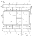
- a pair of pipes 9, 9 constituting part of the scum remover 20 are provided inside both side walls 5 of the water conduit body 2, parallel to each side wall 5 so as to extend in the direction of the flow of the raw water.
- These pipes 9, 9 are made of well-known pipe materials such as steel or synthetic resin, and as shown in Figure 6, a number of discharge members 21 are provided in a row at predetermined intervals along their length.
- the discharge outlet member 21 is made of synthetic resin such as fluororesin, and its external shape is cup-shaped (bowl-shaped, bell-shaped, etc.) with an opening 22 at the bottom. These discharge outlet members 21 are fixed to the pipe 9 with their internal space connected to the inside of the pipe 9, and the opening 22 is positioned vertically downward.
- These pipes 9 are installed so that they are located below the scum layer S that is generated within the water conduit body 2. For example, if scum S accumulates due to operation of the water conduit A and grows to a thickness of, for example, approximately 10 cm, and the scum S is to be discharged from the water conduit body 2 into the scum pit 3, the pipes 9 are installed so that they are slightly below 10 cm from the water surface. The installation position of the pipes 9 varies depending on the sewage treatment plant where the water conduit body 2 is installed, but in any case, they are determined to be below the scum S that is generated.
- the scum removal device 20 includes the pipes 9 described above and a pressure fluid supply unit 23 that supplies compressed air, pressure water, or gas-liquid mixed pressure water to these pipes 9.
- compressed air is shown as an example of the pressure fluid.
- the pipe 9 is arranged along the length of the water conduit body 2 (along the direction of the raw water flow), but is divided into a number of regions S1 to S3 of a predetermined length along the length, and a pressurized fluid supply unit 23 is provided for each of the divided regions S1 to S3. Therefore, a number of pressurized fluid supply units 23 are provided within one water conduit body 2.
- Pressure fluid supply unit 23 In the example shown in Fig. 2, the area is divided into three regions S1 to S3, and therefore three pressure fluid supply units 23 are provided (however, the pressure fluid supply units 23 are not shown in Fig. 4).
- Each pressure fluid supply unit 23 is connected to a pressure fluid pipe 24 that supplies pressure fluid from a pressure supply source.
- This pressure fluid pipe 24 is provided with branch pipes 25 that supply pressure fluid to each of the pressure fluid supply units 23.
- Each branch pipe 25 is provided with a flow rate adjustment valve 26 for controlling the flow rate to the respective pressure fluid supply unit 23.
- the pressurized fluid supply section 23 is configured to form a loop in plan view, with a pair of long tube sections 27, 27 arranged in parallel to each of the pair of pipes 9, 9, and a pair of short tube sections 28, 28 connected to both ends of the long tube sections 27, 27.
- a central connecting pipe 29 that connects the long pipe sections 27, 27 is connected to the approximate center of each of the long pipe sections 27, 27.
- Each branch pipe 25 of the pressurized fluid supply section 23 is connected to the center of the central connecting pipe 29 in the longitudinal direction.
- the long tube sections 27, 27 of the pressurized fluid supply section 23 are provided with a plurality of connecting pipes 30 at a predetermined interval between each other, connecting each of the long tube sections 27, 27 to the pipes 9, 9. Therefore, the pressurized fluid from the pressurized fluid supply source is supplied from the pressurized fluid piping 24 through each branch pipe 25 to each pressurized fluid supply section 23, and is supplied from each pressurized fluid supply section 23 to the pipe 9 through each connecting pipe 30.
- Each pressurized fluid supply section 23, together with the pressurized fluid piping 24 and branch pipes 25, etc., is provided above the water surface of the water conduit body 2. Although it is possible to place these underwater, it is preferable to place them above the water surface since this would hinder the flow of raw water.
- the pipes 9, etc. are shown with dashed lines, which indicate that they are provided underwater.
- scum removal device 20 configured in this manner, when pressure fluid (compressed air) is supplied from each pressure fluid supply unit 23 into the pipes 9, 9, it is released as air bubbles into the raw water from the downward openings 22 of each discharge member 21 (see Figure 6). The released air bubbles then rise along the inner surface of the side wall 5, and are able to remove the scum adhering to the side wall 5.
- pressure fluid compressed air
- a pipe made of an elastic material such as natural rubber or synthetic rubber with multiple slits (long, thin openings) spaced along its length, or a steel pipe with multiple holes (openings) spaced along its length, etc. can also be used.
- a plurality of water injection nozzles for the conduit (hereinafter referred to as above-water nozzles) 11 are provided above the water in the conduit body 2.
- the above-water nozzles 11 are provided slightly above the water surface in the conduit body 2, at a plurality of locations so as to divide the length of the water flow direction in the conduit body 2 at predetermined intervals, and a plurality of nozzles are provided in each location along the width direction of the conduit body 2 (see FIG. 2).
- Water at a predetermined pressure is supplied to each above-water nozzle 11 via a pressure water supply pipe 12.
- the water supplied to the above-water nozzles 11 can be treated water from a sewage treatment plant.
- the above-water nozzles 11 are obliquely installed so that their tip openings face further downward downstream of the water flow in the water conduit body 2. Therefore, when pressurized water is sprayed from each above-water nozzle 11, the sprayed water is supplied downstream to the scum S that has formed in a layer on the water surface of the water conduit body 2, promoting the flow of scum S toward the scum pit 3 (see Figures 3 and 4).
- scum layer S that has grown in a layer of a certain thickness on the water surface is sometimes referred to as "scum layer S.”
- the conduit body 2 is provided with a plurality of water injection nozzles (hereinafter, referred to as submerged nozzles) 13 for the conduit.
- These underwater nozzles 13 are provided in the water just below the water surface in the water conduit body 2, and in a number of units at predetermined intervals in the direction of water flow in the water conduit body 2.
- a number of underwater nozzles 13 are provided at predetermined intervals from each other in the direction perpendicular to the direction of water flow in the water conduit body 2, i.e., across the width of the waterway.
- these underwater nozzles 13 are not provided.
- This underwater nozzle 13 is supplied with water at a predetermined pressure via a pressurized water supply pipe 14.
- pressurized water is supplied from the pressurized water supply pipe 14 to this underwater nozzle 13, the pressurized water is sprayed from an opening facing the scum pit 3 side, thereby promoting the flow of scum S that is attempting to flow toward the scum pit 3 (see Figure 4).
- Treated water from a sewage treatment plant can be used as the water supplied to this underwater nozzle 13.
- the water injection nozzle 11 installed above the water will be described as an above-water nozzle
- the water injection nozzle 13 installed underwater will be described as an underwater nozzle
- the first scum removal device 35 is composed of a scum pit 3 with a movable gate 4, a scum removal device 20, an above-water nozzle 11, an underwater nozzle 13, etc. ( Figures 2 and 3).
- the following describes a sewage treatment method that includes the scum discharge operation in the water conduit A configured as described above.
- Raw water (sewage) is supplied to the water conveyance main body 2, and the supplied raw water is distributed to each primary sedimentation tank 6 via each inlet 7, where sedimentation and separation processing takes place. At this time, scum S gradually forms on the water surface of the water conveyance main body 2.
- Figures 3 and 4 show this state.
- pressurized water is supplied to the underwater nozzle 13 and the abovewater nozzle 11, which breaks down part of the scum layer S and pushes it downstream.
- compressed air is supplied to the pipe 9. This starts the discharge of the scum S into the scum pit 3.
- pressurized water When pressurized water is supplied to the underwater nozzle 13, the pressurized water is sprayed from the underwater nozzle 13 so that the scum S flows towards the scum pit 3.
- the tip of the underwater nozzle 13 is formed facing slightly upwards, which acts to lift the scum S slightly out of the water, causing the scum S to move.
- pressurized water is also sprayed from the above-water nozzle 11 so that the scum S flows towards the scum pit 3.
- the pipes 9, 9 are supplied with fluid from each pressurized fluid supply unit 23 via connecting tubes 30. Because these pressurized fluid supply units 23 are formed in a loop, the pressure inside them is kept approximately uniform. This allows compressed air of approximately uniform pressure to be supplied to the pipes 9 corresponding to each pressurized fluid supply unit 23, and as a result, approximately uniform compressed air is ejected from the openings 22 of all of the discharge port members 21. This means that the scum S that has adhered to the side walls 5 corresponding to each long tube section 27 of the pressurized fluid supply units 23 can be effectively peeled off.
- the amount of compressed air supplied from the pressurized fluid pipe 24 to each pressurized fluid supply unit 23 through each branch pipe 25 can be adjusted by each flow control valve 26. Therefore, by increasing the amount of compressed air supplied to a portion of the multiple pressurized fluid supply units 23 where scum S is likely to accumulate and has a strong adhesive force in the water conduit main body 2, for example, the pressurized fluid supply unit 23 provided at the end of the flow in the water conduit main body 2, the scum S at that portion can be more effectively peeled off.
- the supply flow rate of the pressurized fluid to each pressurized fluid supply unit 23 can be individually controlled by the flow rate adjustment valve 26, and the pressurized fluid can be appropriately supplied according to the adhesion state of the scum, etc., and the scum can be effectively removed.
- multiple pressure fluid supply units 23 are provided in a separate state, they may also be connected.
- Primary sedimentation tank group B As shown in Figures 1 and 2, primary sedimentation tank group B is configured with multiple primary sedimentation tanks 6 installed in parallel, and as described above, sewage received at the sewage treatment plant is received into primary sedimentation tank group B (each primary sedimentation tank 6) via primary sedimentation tank water conduit A.
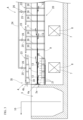
- Figure 7 shows the downstream portion of one primary sedimentation tank 6.
- the sewage received in the primary sedimentation tank 6 moves from one side (upstream side: left side in the illustrated example) of the tank 6 to the other side (downstream side: right side in the illustrated example), i.e., during the flow indicated by arrow d in the figure, the sedimentable substances contained in the sewage settle and are separated.
- the settleable material (sludge) that settles to the bottom of the primary settling tank 6 is collected in a pit located at the bottom of one side of the primary settling tank 6 by a sludge collector (not shown), and then sent via a sludge discharge pipe 15 (see Figure 1) to a sludge treatment facility for treatment.
- the raw water contains floating substances in addition to sedimentation substances, and scum S is generated, which is a collection of floating substances on the water surface of the sedimentation tank 1. Therefore, in the first sedimentation tank 6, the aforementioned sinkable substances are separated, and the scum S is removed by the second scum removal device 60.
- the treated water from which the sedimentable and floating substances (scum S) have been removed is received in the overflow trough 52 located on the other side (downstream side) of the primary sedimentation tank 6.
- the treated water received in the overflow trough 52 is taken out as shown by the arrow e in Figure 7 and sent to the reaction tank (aeration tank) C for biological treatment.
- the second scum removal device 60 is installed downstream of the flow of raw water in the primary sedimentation tank 6, upstream of the overflow trough 52.
- This second scum removal device 60 is provided with a pipe skimmer 61 (for the primary sedimentation tank) for taking in scum.
- the pipe skimmer 61 includes a pipe material 62 with a scum intake port 63, and a rotating mechanism 55 for rotating the pipe material 62.
- the pipe gap 61 is installed so that the pipe material 62 blocks the flow of the water surface. That is, the pipe material 62 is installed horizontally so as to cross the width direction (direction crossing the flow) of the primary sedimentation tank 6, and a slit-shaped opening (scum intake port 63) is provided along the longitudinal direction in the peripheral wall.
- One longitudinal end of the pipe material 62 penetrates one side wall 6a of the primary sedimentation tank 6 in a watertight manner and is supported so as to be freely rotatable, and the other end is supported so as to be freely rotatable on the other side wall 6b of the primary sedimentation tank 6.
- the end of the pipe material 62 that penetrates the side wall 6a is disposed in the scum pit 54 provided on the outside of the side wall 6a.
- a rotating mechanism 55 including a motor is provided on the upper surface of the other side wall 6b of the initial settling tank 6, where the other end of the pipe material 62 is provided.
- This rotating mechanism 55 is configured to be able to rotate the pipe material 62 back and forth around its axis at a predetermined angle.
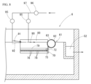
- the pipe material 62 is supported so that the scum intake port 63, which is provided in the longitudinal direction, is positioned above the water surface as its normal position, as shown in Figures 7 and 8.
- the pivoting mechanism 55 rotates as shown by arrow f in Figure 9 (counterclockwise in Figure 9) so that the water surface is positioned approximately in the middle of the width of the scum intake port 63 (the width along the circumference of the pipe material 62).
- the scum S on the water surface flows from the front of the pipe material 62 towards the scum intake port 63, is dropped into the pipe material 62 from the scum intake port 63, and is then sent through the inside of the pipe material 62 to the scum pit 54.
- the position of the scum intake port 63 at this time is the scum intake position, and the position where the scum intake port 63 is located above the water surface is the non-intake position.
- the rotation mechanism 55 may be configured to rotate the pipe material 62 manually without using a motor or the like.
- the scum S discharged into the scum pit 54 is removed from the scum pit 54 as indicated by arrow g ( Figure 7) and sent to a scum treatment facility equipped with a dehydrator (not shown) for treatment.
- the water after removing the scum S is returned upstream and mixed with the raw water for further treatment.
- the pipe material 62 is formed to be longer than the width of the primary sedimentation tank 6, and is arranged so as to cross the water flow direction of the primary sedimentation tank 6.
- the scum intake port 63 provided in the longitudinal direction is formed to be shorter than the width of the primary sedimentation tank 6, and both ends in the longitudinal direction are spaced a predetermined distance from the inner surfaces of the side walls 6a, 6b of the primary sedimentation tank 6.
- the second scum removal device 60 has this pipe gap 61, and a front wall plate 70 and a pair of guide plates 80 that serve as a scum guide mechanism that collects scum S toward the center of the width of the primary settling tank 6.
- the front wall plate 70 and guide plates 80 are provided in front of the pipe material 62 (upstream side), that is, on the side from which the raw water approaches the pipe material 62 (the left side of the pipe material 62 in the illustrated example).
- the front wall panel 70 is made of a steel or synthetic resin plate and has a long and narrow rectangular shape when viewed from the direction of the raw water flow.
- the long side of the rectangle of the front wall panel 70 is set to be slightly longer than the length of the scum intake port 63, and the short side is positioned along the depth direction of the primary sedimentation tank 6.
- the upper end position of the front wall panel 70 is set to be lower than the lower end position of the scum intake port 63 when the pipe material 62 rotates and part of the scum intake port 63 is submerged in water (the lower end position of the scum intake port 63 at the scum intake position).
- the lower end position of the front wall panel 70 extends below the lower position of the pipe material 62.
- One end of the front wall plate 70 in the longitudinal direction (width direction of the sedimentation tank 1) is fixed to the inner surface of one side wall 6a of the sedimentation tank 1 using a support member 71, and the other end is fixed to the inner surface of the other side wall 6b of the sedimentation tank 1 using another support member 71.
- the rear surface (downstream surface) of the front wall plate 70 i.e., the surface opposite the direction in which the raw water flows, is close to the pipe material 62 as far as not interfering with the rotation of the pipe material 62, and the position of the upper edge of the front wall plate 70 is lower than the lower end position of the scum intake port 63 when facing upstream.
- the position of the upper edge of the front wall plate 70 may be at approximately the same height as the lower end position of the scum intake port 63 of the pipe material 62 at the scum intake position.
- the discharge port members 73 are made of synthetic resin such as fluororesin, and are formed in a cup-like (bowl-like, bell-like, etc.) outer shape with an opening 74 at the bottom. These discharge port members 73 are fixed to the fluid ejection pipe 72 with their internal space connected to the inside of the fluid ejection pipe 72, and the opening 74 is positioned vertically downward.
- One longitudinal end of the fluid ejection pipe 72 is closed, and the other end is connected to a fluid supply pipe 76 via a flow rate control valve 75.
- An opening/closing valve 77 such as a gate valve is provided on the fluid supply pipe 76.
- FIGS 7 to 9 show an example in which a front wall plate 70 is provided, this front wall plate 70 is not necessarily required for the scum guide mechanism, and there are cases in which the front wall plate 70 is not provided. However, it is preferable to provide a front wall plate 70, as this creates a wall below the pipe gap 61.
- a fluid ejection pipe 72 having an ejection port member 73 and ejecting pressurized fluid.
- the pair of guide plates 80 have the same shape. These guide plates 80 are also made of the same steel or synthetic resin plate material as the front wall plate 70. These guide plates 80 are rectangular, with their short sides positioned along the depth direction within the sedimentation tank 1. There are cases in which these guide plates 80 are not provided.
- the width of the short side of each guide plate 80 (the dimension along the depth direction of the sedimentation tank 1) is approximately twice as large as the length of the short side of the front wall plate 70 (width; the dimension along the depth direction of the sedimentation tank 1).
- the position of their upper edges is higher than the top surface position of the scum S, and the position of their lower edges is approximately equal to the position of the lower edge of the front wall plate 70 (see Figures 8 and 9).
- Fluid ejection pipes 79 equipped with multiple outlet members 78 are attached using U-bolts or the like near the bottom edge of the front side (upstream side) of these guide plates 80.
- the fluid ejection pipes 79 provided on both guide plates 80 are connected to the fluid supply pipe 76 via the flow control valve 75, similar to the fluid ejection pipe 72 of the front wall plate 70.
- the piping of the fluid ejection pipe 79 on the side wall 6b is shown only partway through, and is connected to the piping shown at the top of the figure at the position indicated by the symbol "Q" in Figure 7.
- both guide plates 80 are fixed using support members 82 so that one longitudinal end abuts against each end of the front wall plate 70 (the upper and lower ends in FIG. 7) and the other longitudinal end abuts against the inner surface of each side wall 6a, 6b of the settling tank 1.
- fix fixing they are carefully attached so that the position of the upper edge is higher than the position of the top surface of the scum S and the position of the lower edge is approximately equal to the position of the lower edge of the front wall plate 70.
- the length of the pair of guide plates 80 is determined by the mounting angle ⁇ at which they are attached to the inner surfaces of both side walls 6a, 6b of the primary sedimentation tank 6. In the example in Figure 7, they are attached at an angle of approximately 15° to the inner surfaces of each side wall 6a, 6b, and are positioned so that the distance between the pair of guide plates 80 gradually increases as they move upstream.
- the purpose of setting the mounting angle ⁇ on the pair of guide plates 80 is to gradually collect the flowing scum S toward the center of the flow, thereby increasing the concentration of the scum S and obtaining scum S with a low moisture content.
- the installation angle ⁇ of the guide plates 80 can be increased to a certain extent.
- the pair of guide plates 80 When the mounting angle ⁇ of the pair of guide plates 80 is brought closer to 0°, they become closer to being parallel to both side walls 6a, 6b of the initial settling tank 6, so the effect of the guide plates 80 in accumulating scum S is reduced. However, the resistance to the scum S is reduced, and the speed at which the scum S moves increases. Also, because the pair of guide plates 80 are provided with the fluid ejection pipes 79 and the water ejection nozzles 90, 91 described below, the time required to eject the scum S is shorter, and therefore the amount of water required for ejection is reduced.
- Water injection nozzles (above water nozzles) 90, 91 (for the first sedimentation tank) shown in Figs. 10A and 10B are provided above the water near the water surface near the second scum removal device 60, which is composed of the front wall plate 70 and a pair of guide plates 80, and water injection nozzles (underwater nozzles) 92 (for the first sedimentation tank) are provided underwater. As shown in Fig.
- the water injection nozzles 90 are provided in a plurality (five in the illustrated example) at a predetermined interval from each other in the direction crossing the sedimentation tank 1 (direction crossing the flow) in the area between the pair of guide plates 80, and the water injection nozzles 91, 92 are provided in a plurality (six in total in the illustrated example) in the same manner as the water injection nozzle 90, slightly upstream of the installation position of the water injection nozzle 90 (outside the gap between the pair of guide plates 80 in the illustrated example).
- Each injection nozzle 90, 91, 92 is configured with a slit 93 that ejects water approximately parallel to the water surface, and a straightening piece 94 that protrudes from the top of the slit 93 and holds the laminar water flow ejected from the slit 93.
- the injection nozzle 90 (above water nozzle) located in the area between the two guide plates 80 is located approximately at the water surface position, and is installed so that the laminar water flow ejected from the slit 93 faces the second scum removal device 60 side (pipe skimmer 61 side).
- three above-water nozzles 91 slightly above the water surface and three underwater nozzles 92 slightly below the water surface are arranged alternately.
- the above-water nozzles 91 are tilted slightly downward to spray water diagonally from above towards the water surface.
- the underwater nozzles 92 are tilted slightly upward to spray water from underwater towards the water surface. Note that in Figures 7 and 8, the above-water nozzles 90, 91 are shown by solid lines, and the underwater nozzles 92 are shown by dashed lines.
- These water injection nozzles 90, 91, and 92 are configured so that the injection amount can be appropriately adjusted using a flow control valve 95, and are connected to a water supply pipe 97 equipped with an on-off valve 96.
- the on-off valves 77, 96 are opened simultaneously with or before the rotation of the pipe skimmer 61. Water is sprayed from the water spray nozzles 90, 91, 92 located upstream onto the scum layer S, eliminating air bubbles adhering to the solid matter in the scum layer S and allowing the solid matter floating to the surface by the air bubbles to settle and separate. The water sprayed downstream accelerates the flow of the water surface, washing the scum downstream.
- the scum layer S is pushed through the guide plates 80 and into the scum intake port 63 of the pipe skimmer 61.
- compressed air is being ejected as a pressurized fluid from the outlet member 78 of the fluid ejection pipe 79 on the surface of the guide plate 80, and the bubbling flow reaches the water surface, so the scum layer S flows away from the surface of the guide plate 80 and is pulled toward the center, and is guided to the scum intake port 63 without adhering to the guide plate 80.
- Compressed air is ejected relatively gently from the fluid ejection pipe 72 at the front surface of the front wall panel 70, and the buoyancy of the air causes the scum S to be lifted and flow into the scum intake port 63.
- the intake of scum S into the scum intake port 63 is induced, and thereafter, the scum S is continuously flowed into the pipe material 62 of the pipe gap 61 one after another.
- the compressed air continues to be ejected from the fluid ejection tube 79 on the guide plate 80 even after the intake of scum S has started, as this prevents scum S from adhering to the guide plate 80 and also removes scum S from the surface of the guide plate 80, facilitating a smooth flow to the scum intake port 63.
- the flow of scum S is promoted by the water flow ejected, and the scum S can be quickly discharged toward the pipe material 62 side of the pipe gap 61.
- the scum S that is drawn into the pipe skimmer 61 is discharged into the scum pit 54 and sent to a scum treatment facility for treatment.
- the second scum removal device 60 configured as described above is arranged so that the pipe material 62 of the pipe skimmer 61 is above the water surface to block the flow path, and is configured to include a front wall plate 70 equipped with a fluid ejection pipe 72, a pair of guide plates 80, and water injection nozzles 90, 91, 92. Therefore, for example, scum can be removed by operating it once a week for about 7 to 10 minutes.
- the scum can be discharged in a shorter time, which reduces the amount of water that flows into the pipe skimmer 61 along with the scum, resulting in an extremely advantageous effect of significantly reducing the amount of power consumed to remove the scum and return it to the raw water.
- the treated water is discharged into the natural environment, the improved water quality reduces the burden on the environment. Therefore, the second scum removal device 60 configured as described above has the excellent feature of being able to contribute to reducing the burden on the natural environment and further energy conservation.
- the second scum removal device 60 configured as described above has the advantage that the main components, the front wall plate 70 equipped with the fluid ejection pipes 72, 79 and the pair of guide plates 80, can be prefabricated in a factory, and can be easily applied to existing settling tanks.
- reaction tank C The reaction tank C is where the treated water from the group of primary sedimentation tanks B is biologically treated, and is treated by advanced treatment methods such as the standard activated sludge process, the anaerobic-anoxic-aerobic process ( A2O process), or the anaerobic-aerobic activated sludge process (AO process) (see Figure 1).
- This reaction tank C receives the treated water from the group of primary sedimentation tanks B, and also receives return sludge from the group of final sedimentation tanks E as necessary for biological treatment, and is the core treatment facility of the sewage treatment plant, but since scum is not removed in this reaction tank C, further explanation will be omitted.
- This final settling tank water conduit D is configured to receive treated water from the reaction tank C and distribute and supply the treated water as raw water to each of the final settling tanks 100 in the final settling tank group E (see FIG. 1).
- This final settling tank water conduit D is equipped with a scum removing device similar to the first scum removing device 35 (see FIG. 1) installed in the primary settling tank water conduit A described above with reference to FIGS. 2 to 4. The configuration is almost the same as that of the first scum removing device 35, so further description will be omitted.
- the above-water nozzle 11 shown in Figures 2 to 4 may be omitted. Of course, it can be installed if necessary depending on the nature of the scum.
- Figure 11 is a plan view of the downstream portion of one of the final sedimentation tanks 100 in the final sedimentation tank group E. Since each final sedimentation tank 100 in the initial sedimentation tank group E has the same configuration, the following explanation will be given using this one final sedimentation tank 100.
- the settledable substances contained in the raw water settle and are separated.
- the settleable substances (sludge) that settle to the bottom of the final sedimentation tank 100 are collected in a pit provided at the bottom of one side of the final sedimentation tank 100 by a sludge collector, and then sent as return sludge via the sludge discharge pipe 101 (see Figure 1) to reaction tank C for use, and the remaining sludge is sent as excess sludge to a sludge treatment facility for treatment.
- the treated water from the final sedimentation tank 100 from which sedimentable substances have been separated and the scum has been removed by a third scum removal device 105, which will be described in detail later, is received in an overflow trough 102 provided on the other side of the final sedimentation tank 100.
- the treated water received in the overflow trough 102 is taken out as shown by the arrow i in Figure 11, disinfected, and then discharged.
- the third scum removal device 105 installed in this final sedimentation tank 100 is composed of a pipe skimmer 106 for the final sedimentation tank and a water injection nozzle 107.
- the pipe skimmer 106 comprises a pipe material 108 made of steel or synthetic resin and a rotation mechanism 112 that rotates the pipe material 108.
- the pipe material 108 has two openings (scum intake ports) 109, 110 extending in the longitudinal direction, and is arranged to block the surface flow of raw water in the final sedimentation tank 100. That is, one longitudinal end of the pipe material 108 passes through one side wall (the upper side wall in FIG. 11) 100a of the final sedimentation tank 100 in a watertight manner and is arranged to be freely rotatable, and the other end is arranged to be freely rotatable on the other side wall 100b of the final sedimentation tank 100.
- the end of the pipe material 108 that penetrates the side wall 100a is located in a scum pit 111 that is provided on the outside of the side wall 100a. Therefore, the scum in the pipe material 108 can be discharged into the scum pit 111.
- the scum discharged into the scum pit 111 is taken out as shown by arrow j, and sent to a scum processing facility (not shown) for processing.
- Each opening (upstream scum intake port 109, downstream scum intake port 110) of the pipe material 108 is formed parallel to each other at intervals in the circumferential direction of the pipe material 108.
- the positions of both ends of each opening 109, 110 are respectively located near the side walls 100a, 100b of the final sedimentation tank 100.
- the length of each opening 109, 110 is approximately equal to the width of the final sedimentation tank 100.
- a rotation mechanism 112 including a motor is provided on the upper surface of the other side wall 100b of the final sedimentation tank 100.
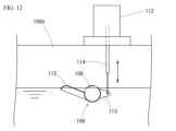
- This rotation mechanism 112 is configured to be able to rotate the pipe material 108 back and forth within a predetermined rotation angle by driving a drive rod 114 connected to an arm 113 protruding from one end of the pipe material 108 in the vertical direction.
- the rotation mechanism 112 may be configured to rotate the pipe material 108 back and forth manually without providing a motor or the like.
- a scum guide plate (guide plate) 115 is provided on one side wall of the pipe material 108.
- This scum guide plate 115 is a rectangular planar guide plate made of steel or synthetic resin, and is provided so as to extend a predetermined distance upstream (to the left in the illustrated example) from the position of the lower edge that forms one opening 109 of the pipe gap 106 (an opening located upstream of the final sedimentation tank 100; upstream scum intake port).
- one end edge of the scum guide plate 115 (the right edge in the figure), which corresponds to the base of the scum guide plate 115, is joined to the lower edge of the opening 109, and extends at an angle to the radial direction of the pipe material 108.
- the guide plate 115 is curved so that the other end edge, i.e., the tip 115a of the scum guide plate 115, is convex on the upper surface.
- the opening (downstream scum intake port) 110 is positioned next to the opening 109 downstream when the opening 109 is positioned above the water surface.
- the tip of the scum guide plate 115 is preventing the entry of scum S ( Figure 13A)
- the opening 110 is positioned above the water surface.
- the pipe material 108 is rotated in the opposite direction to when taking in scum upstream (clockwise in Figures 13A-C)
- the lower edge of the opening 110 is positioned below the water surface toward the downstream side.
- the rotation of the pipe material 108 by the rotation mechanism 112 is controlled by a programmable controller (not shown) that controls the entire final sedimentation tank 100, including the third scum removal device 105.
- the water injection nozzle 107 is placed underwater and sprays pressurized water toward the water surface where scum S has risen to the surface, creating a water flow from underwater that sweeps the scum floating to the surface downstream.
- This water injection nozzle 107 is equipped with a flat cylindrical tip 121 that is wider than it is tall, and a valve body 123 that is provided within the cylindrical tip 121 and can open and close an opening 122 of the cylindrical tip 121.
- this valve body 123 is supported by a shaft 124 within the cylindrical tip portion 121 so as to be freely rotatable, and it rotates up and down between a position where it abuts against the underside of the upper wall 121a of the cylindrical tip portion 121, forming an opening 122 between the underside of the valve body 123 and the lower wall 121b of the cylindrical tip portion 121, as shown in FIG. 14A, and a position where it abuts against the upper surface of the lower wall 121b of the cylindrical tip portion 121, closing the opening 122, as shown in FIG. 14B.
- the valve body 123 has a weight that rotates downwards under its own weight when pressurized water is not supplied, thereby closing the opening 122, and rotates upwards under the pressure of the pressurized water when pressurized water is supplied, thereby opening the opening 122.
- a rising plate 124a is integrally formed at the tip of the valve body 123, which closes the gap 130 that occurs between the upper surface of the valve body 123 and the upper wall 121a of the cylindrical tip portion 121 when the opening 122 is closed as shown in Figure 14B.
- These water injection nozzles 107 are provided underwater near the water surface at a predetermined distance upstream from the tip of the scum guide plate 115, and are spaced apart at predetermined intervals in a direction perpendicular to the flow in the final sedimentation tank 100.
- Each water injection nozzle 107 is connected to a water supply pipe 126 equipped with a flow control valve 125 midway, through which pressurized water is supplied.
- the direction of the pressurized water spray from each water spray nozzle 107 is set to face the pipe material 108 (from the upstream side to the downstream side). Therefore, when pressurized water is sprayed from each water spray nozzle 107, the flow rate of the surface water in the final sedimentation tank 100 is increased, and the scum S floating on the surface of the surface water can be sent toward the pipe material 108.
- the majority of the scum S has been removed from the primary settling basin water conduit A, the primary settling basin group B, and the final settling basin water conduit D, so little scum is generated. Therefore, unlike the primary settling basin water conduit A, etc., where scum adheres to the walls or sticks together, the scum is dispersed and floating on the water surface.
- the amount of water sprayed (spray pressure) from the water spray nozzle 107 is set to be less than the amount of water sprayed (spray pressure) from the underwater nozzles 13, 92, etc., provided on the primary sedimentation tank conduit A, the primary sedimentation tank group B, and the final sedimentation tank conduit D, etc., and is designed so that the scum S is not destroyed or scattered by the water spray, causing it to become cloudy or dissolve in the treated water.
- a fluid ejection pipe 132 having an outlet member 131 is provided on the inside of the side walls 100a, 100b, and compressed air is ejected from underwater to move scum near the side walls 100a, 100b toward the center.
- the fluid ejection pipe 132 may be omitted.
- water spray nozzles 127 that spray water toward the scum guide plate 115.
- These water spray nozzles 127 are well-known cleaning water spray nozzles that can separate and flush away contaminants that are lightly attached to objects, and are connected to a water supply pipe 129 that has a flow rate control valve 128 midway.
- the final sedimentation tank 100 is carrying out the sedimentation process, and the openings 109, 110 of the pipe skimmer 106 are located above the water surface, as shown in Figure 13A. Upstream of the opening 109, the tip 115a of the scum guide plate 115 protrudes above the water surface, holding back the scum S. A thin film of scum S is generated on the water surface upstream of this scum guide plate 115.
- the pressurized water sprayed from each water injection nozzle 107 is directed toward the opening 109 of the pipe material 108.
- the flow of the raw water which has a slow flow rate due to the final settling tank 100, is accelerated only at the surface by the water spray from the water injection nozzle 107, and the scum floating on the water surface is efficiently sent to the opening 109 of the pipe material 108.
- the amount of water sprayed from the water spray nozzle 107 is small and sprayed relatively slowly, so the scum S floats on the water surface or remains in a thin film form as it moves with the current and is taken into the pipe material 108 through the opening 109 and discharged into the scum pit 111.
- the scum guide plate 115 is positioned near the water surface on the upstream side of the pipe material 108, so the scum can be efficiently guided to the opening 109 without being affected by rising currents from below. Therefore, with this pipe skimmer 106, the scum can be removed in a short time, for example by operating it once a day for about 5 to 7 minutes.
- the scum S discharged into the scum pit 111 is sent to a scum treatment facility for treatment.
- the treated water is passed through the overflow trough 102 downstream of the pipe skimmer 106, taken out from the overflow trough 102 as shown by the arrow i in Figure 11, disinfected, and then discharged.
- the rotational position of the pipe material 108 is returned to the state shown in FIG. 13A, and, as necessary, spraying of water from the water spray nozzle 127 is started to clean the surface of the scum guide plate 115.
- the water used to clean the guide plate 115 is allowed to flow through the opening 109 into the pipe material 108.
- the surface of the scum guide plate 115 is cleaned by the spraying of water from the water spray nozzle 127, which effectively prevents scum S from sticking to the scum guide plate 115 and interfering with the next scum removal.
- the third scum removal device 105 in the final settling tank group E allows the small amount of scum S that is generated to flow relatively slowly, and can capture it in the pipe skimmer 106 while it floats on the water surface or remains in the form of a thin film, without clouding the treated water.
- the third scum removal device 105 configured as described above has properties that can greatly contribute to so-called eco-measures. Furthermore, by providing the scum guide plate 115 with a curved tip, the floating scum S can be efficiently caused to flow into the opening 109, which also reduces the amount of water flowing into the pipe gap 106. In addition, the upper surface of the scum guide plate 115 is cleaned by spraying water from the watering nozzle 127, preventing any problems with the next scum removal.
- the scum removal system in the sewage treatment plant configured as above can efficiently remove scum using the first scum removal device 35 installed in the first settling tank conduit A, the second scum removal device 60 installed in the first settling tank group B, the scum removal device (similar in configuration to the scum removal device 35) installed in the final settling tank conduit D, and the third scum removal device 105 installed in the final settling tank group E, thereby increasing the efficiency of scum removal throughout the sewage treatment plant.
- the quality of treated water can be improved and the burden on the natural environment can be reduced, while scum removal through the pipe gaps can be completed in a short time and the associated backflow water can be reduced, resulting in energy savings and a significant reduction in the cost of scum treatment at sewage treatment plants.
- the fluid ejection pipes 72 and 79 are provided with an ejection port member 73, but the fluid ejection pipes themselves may have small holes formed therein without providing the ejection port member 73.
- the amount of compressed air can be increased.
- the fluid ejected from the fluid ejection pipes 72 and 79 is compressed air, the same effect can be obtained with a water flow or pressurized water containing air bubbles.
- Scum can be efficiently removed by scum removal equipment installed in the primary sedimentation tank water conduit, the primary sedimentation tank, the final sedimentation tank water conduit, and the final sedimentation tank according to the respective conditions. This improves the quality of treated water, reducing the burden on the environment when it is discharged into the natural environment. In addition, the amount of water that flows into the pipe gap together with the scum is small and the scum can be removed in a short time, so the amount of water returned upstream from the pipe gap is reduced, which reduces the associated amount of electricity used, resulting in energy savings and reduced scum treatment costs at sewage treatment plants.
Landscapes
- Chemical & Material Sciences (AREA)
- Analytical Chemistry (AREA)
- Life Sciences & Earth Sciences (AREA)
- Hydrology & Water Resources (AREA)
- Engineering & Computer Science (AREA)
- Environmental & Geological Engineering (AREA)
- Water Supply & Treatment (AREA)
- Organic Chemistry (AREA)
- Removal Of Floating Material (AREA)
Priority Applications (2)
| Application Number | Priority Date | Filing Date | Title |
|---|---|---|---|
| JP2025504466A JP7668076B1 (ja) | 2023-09-14 | 2024-08-22 | 下水処理場におけるスカム除去システム |
| AU2024340877A AU2024340877A1 (en) | 2023-09-14 | 2024-08-22 | Scum removal system in sewage treatment plant |
Applications Claiming Priority (2)
| Application Number | Priority Date | Filing Date | Title |
|---|---|---|---|
| JP2023-149311 | 2023-09-14 | ||
| JP2023149311 | 2023-09-14 |
Publications (1)
| Publication Number | Publication Date |
|---|---|
| WO2025057686A1 true WO2025057686A1 (ja) | 2025-03-20 |
Family
ID=95022224
Family Applications (1)
| Application Number | Title | Priority Date | Filing Date |
|---|---|---|---|
| PCT/JP2024/029787 Pending WO2025057686A1 (ja) | 2023-09-14 | 2024-08-22 | 下水処理場におけるスカム除去システム |
Country Status (3)
| Country | Link |
|---|---|
| JP (1) | JP7668076B1 (https=) |
| AU (1) | AU2024340877A1 (https=) |
| WO (1) | WO2025057686A1 (https=) |
Citations (6)
| Publication number | Priority date | Publication date | Assignee | Title |
|---|---|---|---|---|
| JP2002321000A (ja) * | 2001-04-26 | 2002-11-05 | Asahi Tec Corp | スカム処理方法及び装置 |
| JP2011088048A (ja) * | 2009-10-21 | 2011-05-06 | Utsunomiya Kogyo Kk | スカム除去装置 |
| JP2011240271A (ja) * | 2010-05-19 | 2011-12-01 | Utsunomiya Kogyo Kk | スカム除去装置 |
| JP2017100114A (ja) * | 2015-12-04 | 2017-06-08 | 東京都下水道サービス株式会社 | スカム拡散装置 |
| JP7018552B1 (ja) * | 2020-12-08 | 2022-02-10 | 宇都宮工業株式会社 | スカム除去装置用噴出ノズル及びそのスカム除去装置用噴出ノズルを備えた導水渠 |
| JP7112795B1 (ja) * | 2020-09-17 | 2022-08-04 | 宇都宮工業株式会社 | 導水渠システム |
Family Cites Families (1)
| Publication number | Priority date | Publication date | Assignee | Title |
|---|---|---|---|---|
| JP3943551B2 (ja) * | 2004-01-29 | 2007-07-11 | 宇都宮工業株式会社 | スカム除去装置 |
-
2024
- 2024-08-22 AU AU2024340877A patent/AU2024340877A1/en active Pending
- 2024-08-22 WO PCT/JP2024/029787 patent/WO2025057686A1/ja active Pending
- 2024-08-22 JP JP2025504466A patent/JP7668076B1/ja active Active
Patent Citations (6)
| Publication number | Priority date | Publication date | Assignee | Title |
|---|---|---|---|---|
| JP2002321000A (ja) * | 2001-04-26 | 2002-11-05 | Asahi Tec Corp | スカム処理方法及び装置 |
| JP2011088048A (ja) * | 2009-10-21 | 2011-05-06 | Utsunomiya Kogyo Kk | スカム除去装置 |
| JP2011240271A (ja) * | 2010-05-19 | 2011-12-01 | Utsunomiya Kogyo Kk | スカム除去装置 |
| JP2017100114A (ja) * | 2015-12-04 | 2017-06-08 | 東京都下水道サービス株式会社 | スカム拡散装置 |
| JP7112795B1 (ja) * | 2020-09-17 | 2022-08-04 | 宇都宮工業株式会社 | 導水渠システム |
| JP7018552B1 (ja) * | 2020-12-08 | 2022-02-10 | 宇都宮工業株式会社 | スカム除去装置用噴出ノズル及びそのスカム除去装置用噴出ノズルを備えた導水渠 |
Also Published As
| Publication number | Publication date |
|---|---|
| AU2024340877A1 (en) | 2025-09-11 |
| JP7668076B1 (ja) | 2025-04-24 |
| JPWO2025057686A1 (https=) | 2025-03-20 |
Similar Documents
| Publication | Publication Date | Title |
|---|---|---|
| JP5249237B2 (ja) | スカム除去装置 | |
| JP5443122B2 (ja) | スカム除去装置 | |
| JP7112794B1 (ja) | 導水渠並びに沈殿池 | |
| US5811011A (en) | Biological treatment of wastewater | |
| JP7668076B1 (ja) | 下水処理場におけるスカム除去システム | |
| CN114916226A (zh) | 浮渣去除装置用喷出喷嘴及具备该浮渣去除装置用喷出喷嘴的导水渠 | |
| JP3943551B2 (ja) | スカム除去装置 | |
| JP7112795B1 (ja) | 導水渠システム | |
| JP7748145B2 (ja) | スカム剥離装置及び導水渠並びに沈殿池 | |
| JP7769442B2 (ja) | スカム除去装置 | |
| KR101166327B1 (ko) | 폐수처리용 다열주입식 가압부상조 | |
| JP5891197B2 (ja) | スカム除去装置 | |
| JP2005152777A (ja) | ろ過槽 | |
| JP3200810B2 (ja) | フロート式上澄水集水装置 | |
| CN2749877Y (zh) | 气浮池水射式水力自动排渣装置 | |
| KR100488471B1 (ko) | 하수 및 오폐수 3차처리시스템의 역세척장치 | |
| JP2004024965A (ja) | 生物反応槽におけるスカム排出方法及びその装置 | |
| US12410080B2 (en) | Wastewater filtering method and apparatus comprising filter media of different sizes | |
| JPH11347377A (ja) | 固液分離装置及びその洗浄方法 | |
| KR200305743Y1 (ko) | 하수 및 오폐수 3차처리시스템의 역세척장치 | |
| JPH09299941A (ja) | スカム除去装置 | |
| JPH07102283B2 (ja) | 沈砂池構造 | |
| HK40071766B (en) | Jet nozzle for scum removal device, and water conduit provided | |
| JP2004136244A (ja) | スカム処理装置 |
Legal Events
| Date | Code | Title | Description |
|---|---|---|---|
| ENP | Entry into the national phase |
Ref document number: 2025504466 Country of ref document: JP Kind code of ref document: A |
|
| WWE | Wipo information: entry into national phase |
Ref document number: 2025504466 Country of ref document: JP |
|
| 121 | Ep: the epo has been informed by wipo that ep was designated in this application |
Ref document number: 24865190 Country of ref document: EP Kind code of ref document: A1 |
|
| WWE | Wipo information: entry into national phase |
Ref document number: AU2024340877 Country of ref document: AU |
|
| REG | Reference to national code |
Ref country code: BR Ref legal event code: B01A Ref document number: 112025018376 Country of ref document: BR |
|
| ENP | Entry into the national phase |
Ref document number: 2024340877 Country of ref document: AU Date of ref document: 20240822 Kind code of ref document: A |
|
| WWE | Wipo information: entry into national phase |
Ref document number: 2601001073 Country of ref document: TH |
|
| WWE | Wipo information: entry into national phase |
Ref document number: 2024865190 Country of ref document: EP |