WO2025057322A1 - 指令値又は教示点を補正する装置及び方法、レーザ加工システム、並びに、コンピュータプログラム - Google Patents
指令値又は教示点を補正する装置及び方法、レーザ加工システム、並びに、コンピュータプログラム Download PDFInfo
- Publication number
- WO2025057322A1 WO2025057322A1 PCT/JP2023/033312 JP2023033312W WO2025057322A1 WO 2025057322 A1 WO2025057322 A1 WO 2025057322A1 JP 2023033312 W JP2023033312 W JP 2023033312W WO 2025057322 A1 WO2025057322 A1 WO 2025057322A1
- Authority
- WO
- WIPO (PCT)
- Prior art keywords
- laser
- command value
- movement
- teaching point
- workpiece
- Prior art date
- Legal status (The legal status is an assumption and is not a legal conclusion. Google has not performed a legal analysis and makes no representation as to the accuracy of the status listed.)
- Pending
Links
Images









Classifications
-
- B—PERFORMING OPERATIONS; TRANSPORTING
- B23—MACHINE TOOLS; METAL-WORKING NOT OTHERWISE PROVIDED FOR
- B23K—SOLDERING OR UNSOLDERING; WELDING; CLADDING OR PLATING BY SOLDERING OR WELDING; CUTTING BY APPLYING HEAT LOCALLY, e.g. FLAME CUTTING; WORKING BY LASER BEAM
- B23K26/00—Working by laser beam, e.g. welding, cutting or boring
-
- B—PERFORMING OPERATIONS; TRANSPORTING
- B23—MACHINE TOOLS; METAL-WORKING NOT OTHERWISE PROVIDED FOR
- B23K—SOLDERING OR UNSOLDERING; WELDING; CLADDING OR PLATING BY SOLDERING OR WELDING; CUTTING BY APPLYING HEAT LOCALLY, e.g. FLAME CUTTING; WORKING BY LASER BEAM
- B23K26/00—Working by laser beam, e.g. welding, cutting or boring
- B23K26/02—Positioning or observing the workpiece, e.g. with respect to the point of impact; Aligning, aiming or focusing the laser beam
- B23K26/04—Automatically aligning, aiming or focusing the laser beam, e.g. using the back-scattered light
- B23K26/046—Automatically focusing the laser beam
Definitions
- a laser processing system includes a moving machine that moves the workpiece and the laser processing head relative to one another (for example, Patent Document 1).
- an apparatus for correcting a command value for laser processing a workpiece includes a movement control unit that operates a moving machine that moves the workpiece and a laser emission port that emits laser light generated by a laser oscillator relatively according to a predetermined speed command value, and moves the workpiece along a predetermined movement path; a laser oscillation control unit that operates the laser oscillator according to a predetermined laser output command value, and causes the laser oscillator to generate laser light; a gap control execution unit that operates the moving machine to maintain a constant distance between the laser emission port and the workpiece during laser processing; and a command correction unit that corrects the speed command value or the laser output command value based on the amount of movement of the moving machine in a direction perpendicular to the movement path during laser processing.
- an apparatus for correcting a predetermined teaching point for laser processing of a workpiece includes a movement control unit that moves a moving machine that relatively moves a laser emission port that emits laser light generated by a laser oscillator and the workpiece along a movement path defined by a first teaching point and a second teaching point, a gap control execution unit that operates the moving machine to maintain a constant distance between the laser emission port and the workpiece, a movement amount acquisition unit that acquires the amount of movement of the moving machine in a direction perpendicular to the movement path while moving from the first teaching point to the second teaching point, and a teaching point correction unit that, when the movement distance of the laser light that moves relatively on the workpiece while the moving machine moves from the first teaching point to the second teaching point is greater than the length of the movement path, corrects the first teaching point or the second teaching point based on the movement amount acquired by the movement amount acquisition unit so that the movement distance matches the length.
- a method for correcting a command value for laser processing a workpiece includes operating a moving machine that moves the workpiece and a laser emission port that emits laser light generated by a laser oscillator relatively according to a predetermined speed command value, moving the workpiece along a predetermined movement path, operating the laser oscillator according to a predetermined laser output command value to cause the laser oscillator to generate laser light, operating the moving machine to maintain a constant distance between the laser emission port and the workpiece during laser processing, and correcting the speed command value or the laser output command value based on the amount of movement of the moving machine during laser processing in a direction perpendicular to the movement path.
- a method for correcting a predetermined teaching point for laser processing of a workpiece includes moving a moving machine that moves a laser emission port that emits laser light generated by a laser oscillator relative to the workpiece along a movement path defined by a first teaching point and a second teaching point, operating the moving machine so as to maintain a constant distance between the laser emission port and the workpiece, acquiring an amount of movement of the moving machine in a direction perpendicular to the movement path while moving from the first teaching point to the second teaching point, and, if the movement distance of the laser light that moves relatively on the workpiece while the moving machine moves from the first teaching point to the second teaching point is greater than the length of the movement path, correcting the first teaching point or the second teaching point based on the acquired movement amount so that the movement distance matches the length.
- FIG. 1 is a schematic diagram of a robot system according to an embodiment.
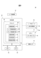
- FIG. 2 is a block diagram of the robot system shown in FIG. 1 .
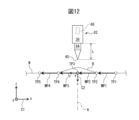
- FIG. 13 is a diagram showing teaching points taught for laser processing. 13 is a diagram for explaining the positions of the laser processing head and TCP when laser processing a workpiece having a convex portion.
- FIG. 5 shows the position of the TCP moving on the protrusion shown in FIG. 4.
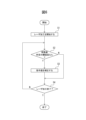
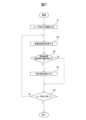
- 3 is a flowchart of the functions of the robot system shown in FIG. 2 . A modified example of the flow in FIG. 6 is shown.
- FIG. 13 is a schematic diagram of a robot system according to another embodiment.
- FIG. 9 is a block diagram of the robot system shown in FIG. 8 .
- FIG. 9 is an enlarged view of the laser processing head shown in FIG. 8 .
- 11 shows the laser processing head shown in FIG. 10 in a retracted state of the movable nozzle.
- 9 is a diagram for explaining the positions of the laser processing head and the TCP when the robot system shown in FIG. 8 performs laser processing on a workpiece having a convex portion.
- FIG. 2 illustrates another function of the robot system shown in FIG. 1 .
- 4 is a diagram for explaining an incident angle of a laser beam to a workpiece.
- FIG. 1 is a graph showing the relationship between the angle of incidence of laser light with respect to a workpiece and the absorptance of the workpiece.
- FIG. 13 shows an example of a data table in which the incident angle, the speed command value, and the laser output command value are stored in association with each other. 1.
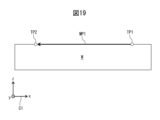
- a further function of the robot system shown in FIG. FIG. 13 is a diagram showing teaching points taught for laser processing.
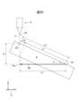
- 20 is a diagram for explaining the positions of the laser processing head and the TCP when a movement operation is performed when the workpiece shown in FIG. 19 is tilted.
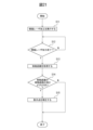
- FIG. 19 is a flowchart of the functions of the robot system shown in FIG. 18.
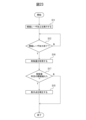
- FIG. 13 is a diagram for explaining a method of correcting a teaching point. A modified example of the flow of FIG. 21 is shown. 1.
- the laser processing system 10 is a system that performs laser processing (laser welding, laser cutting, etc.) on a workpiece W.
- the laser processing system 10 includes a robot 12, a laser processing head 14, a distance measurement sensor 16, a laser oscillator 18, and a control device 20.
- the robot 12 moves the laser processing head 14 relative to the workpiece W.
- the robot 12 is a vertical articulated robot, and has a robot base 22, a rotating body 24, a lower arm 26, an upper arm 28, and a wrist 30.
- the robot base 22 is fixed to the floor of the work cell or on an automated guided vehicle (AGV).
- the rotating body 24 is mounted on the robot base 22 so as to be rotatable around a vertical axis.
- the lower arm 26 is mounted on the rotating body 24 so as to be rotatable around a horizontal axis.
- the upper arm 28 is rotatably mounted on the tip of the lower arm 26.
- the wrist 30 has a wrist base 30a mounted on the tip of the upper arm 28 so as to be rotatable around two axes that are perpendicular to each other, and a wrist flange 30b rotatably mounted on the wrist base 30a.
- Each component of the robot 12 i.e., the robot base 22, the rotating body 24, the lower arm 26, the upper arm 28, and the wrist 30
- a plurality of servo motors 32 ( Figure 2).
- these servo motors 32 rotate each movable component of the robot 12 (i.e., the rotating body 24, the lower arm 26, the upper arm 28, the wrist base 30a, and the wrist flange 30b) around a drive axis.
- the robot 12 moves the laser processing head 14.
- Each servo motor 32 is provided with a rotation detection sensor (encoder, Hall element, etc.) that detects the rotational position of the servo motor 32.
- Each rotation detection sensor supplies detection data Dr of the detected rotational position to the control device 20.
- the nozzle 38 is hollow and is provided at the tip of the head body 36.
- the nozzle 38 has a truncated cone shape with a cross-sectional area that decreases from the base end to the tip, and a laser emission port 40 is formed at the tip.
- a hollow chamber is formed inside the head body 36 and the nozzle 38, and assist gas is supplied into the chamber from an external assist gas supply device (not shown).
- the laser light LB generated by the laser oscillator 18 propagates through the chamber and is emitted along the optical axis A from the laser emission port 40 together with the assist gas.
- a robot coordinate system C1 and a tool coordinate system C2 are set in advance for the robot 12.
- the robot coordinate system C1 is a control coordinate system C for controlling the operation of each movable component of the robot 12 (i.e., the rotating body 24, the lower arm 26, the upper arm 28, the wrist base 30a, and the wrist flange 30b).
- the robot coordinate system C1 is fixed to the robot base 22 so that its origin is located at the center of the robot base 22 and its z axis is parallel to (specifically, coincides with) the rotation axis of the rotating body 24.
- the tool coordinate system C2 is a control coordinate system C that defines the positions of the wrist flange 30b and the laser processing head 14 in the robot coordinate system C1.
- the origin of the tool coordinate system C2 (so-called Tool Center Point: TCP) is placed at the position of the focal point FP of the laser light LB emitted from the laser emission port 40 by the laser processing head 14, and the z-axis of the tool coordinate system C2 is set to be parallel to (specifically, coincident with) the optical axis A.
- the TCP is a control point that represents the positions of the robot 12 (specifically, the wrist flange 30b) and the laser processing head 14 in the robot coordinate system C1.
- the processor 50 can determine the coordinate P of the TCP in the robot coordinate system C1 at any point in time ⁇ based on the detection data Dr obtained from the rotation detection sensor described above.
- This coordinate P represents the position P of the wrist flange 30b and the laser processing head 14 in the robot coordinate system C1 at the point in time ⁇ .
- the TCP may be set at the center of the laser emission port 40.
- the processor 50 of the control device 20 sets a tool coordinate system C2 representing the target position in the robot coordinate system C1, and generates a command to each servo motor 32 of the robot 12 to position the laser processing head 14 at the position represented by the set tool coordinate system C2.
- the control device 20 operates the robot 12 to move the laser processing head 14 to any position in the robot coordinate system C1.
- the robot 12 constitutes a mobile machine that moves the laser processing head 14 (i.e., the laser emission port) and the workpiece W relatively.
- the robot coordinate system C1 and the tool coordinate system C2 constitute a control coordinate system C for automatically controlling the operation of the robot 12.
- TCP the laser processing head 14
- teaching points TP1 to TP5 are taught in advance along the surface of the workpiece W.
- the surface of the workpiece W is positioned parallel to the xy plane of the robot coordinate system C1. Therefore, teaching points TP1 to TP5 are determined along the xy plane of the robot coordinate system C1.
- teaching points TPn are defined as command codes in the operation program PG1 for the laser processing LP.
- the processor 50 operates the robot 12 to position the laser processing head 14 (TCP) in the order of teaching points TP1 ⁇ TP2 ⁇ TP3 ⁇ TP4 ⁇ TP5.
- the movement path MPn is defined to extend along (specifically, parallel to) the x-y plane of the robot coordinate system C1.
- a speed command value V is determined in advance, which defines the speed V when the laser processing head 14 is moved along the movement path MPn from the teaching point TPn to the teaching point TPn+1.
- This speed command value V is determined in advance by the operator as a laser processing condition, and is defined as a command code in the operation program PG1. Note that a different speed command value V may be set for each movement path MPn, or a common speed command value V may be set for all movement paths MP1 to MP4.
- the direction of the movement path MPn coincides with the negative x-axis direction of the robot coordinate system C1. Furthermore, in the following explanation, when the robot 12 is moved along the movement path MPn in the movement operation LP1, the laser processing head 14 is maintained in a position in which the z-axis (i.e., the optical axis A) of the tool coordinate system C2 is parallel to the z-axis of the robot coordinate system C1 (in other words, perpendicular to the movement path MPn).
- the z-axis i.e., the optical axis A
- the processor 50 executes gap control LP2 in the laser processing LP, which causes the robot 12 to operate so as to maintain a constant distance d between the laser emission port 40 and the workpiece W. More specifically, the processor 50 executes a gap control program PG2 for the gap control LP2.
- the processor 50 moves the laser processing head 14 by operating the robot 12 so that the distance d matches a predetermined target distance dt based on the measurement data Dd obtained from the distance sensor 16.
- the target distance dt is specified as a command code in the gap control program PG2.
- the processor 50 uses a movement operation LP1 to move the laser processing head 14 along the movement path MPn in the negative x-axis direction of the robot coordinate system C1, and uses gap control LP2 to move the laser processing head 14 in the z-axis direction of the robot coordinate system C1 so that the distance d matches the target distance dt. In this way, the distance d is maintained constant during the movement operation LP1. Therefore, in this embodiment, the processor 50 functions as a gap control execution unit 64 (FIG. 2) that executes gap control LP2.
- the processor 50 performs a laser light generating operation LP3 in which the laser oscillator 18 is operated in accordance with a predetermined laser output command value O, together with a movement operation LP1 and gap control LP2, to cause the laser oscillator 18 to generate laser light LB.
- the processor 50 functions as a laser oscillation control unit 66 (FIG. 2) that performs the laser light generating operation LP3.
- the laser output command value O has, for example, a laser power command value Op, a frequency command value Of, and a duty ratio command value Od.
- the laser power command value Op specifies the laser power Op [kW] of the output laser light LB.
- the frequency command value Of specifies the frequency Of [Hz] of the laser light LB when generating pulsed laser light.
- the duty ratio command value Od specifies the duty ratio Od [%] of the laser light LB.
- the laser output command value O (laser power command value Op, frequency command value Of, duty ratio command value Od) is determined in advance by the operator as a laser processing condition. As described above, the processor 50 performs laser processing LP on the workpiece W by executing the movement operation LP1, gap control LP2, and laser light generation operation LP3 in parallel.
- the gap control LP2 causes the laser processing head 14 (TCP) to move along the convex portion B, and as a result, it is positioned at position TP3' shifted from teaching point TP3 in a direction perpendicular to the movement path MP2, i.e., in the positive direction of the z axis of the robot coordinate system C1.
- Position P1 shown in Figure 5 indicates the position of the TCP at any time ⁇ 1 while the robot 12 moves the laser processing head 14 along the convex portion B.
- Position P2' indicates a position that has the same x coordinate in the robot coordinate system C1 as position P2, and the same z coordinate in the robot coordinate system C1 as position P1.
- the coordinates of positions P1, P2, and P2' in the robot coordinate system C1 are P1 (x1, y1, z1), P2 (x2, y1, z2), and P2' (x2, y1, z1), respectively.
- This distance ⁇ 2 corresponds to the amount of movement ⁇ 2 by which the robot 12 moves the laser processing head 14 in a direction perpendicular to the movement path MP2 (i.e., in the z-axis direction of the robot coordinate system C1) by means of gap control LP2.
- the robot 12 moves the laser processing head 14 along the movement path MP2 in the negative x-axis direction of the robot coordinate system C1 at a speed V specified by the speed command value V.
- the moving speed v of the laser light LB when the laser processing head 14 is moved in the section between teaching points TP3 and TP4 can also be calculated in a similar manner.
- the moving speed v of the laser light LB irradiated to the workpiece W increases, the amount of heat input of the laser light LB per unit area of the workpiece W can decrease.
- the laser light LB is a pulsed laser light, the wave number of the laser light LB incident on the workpiece W per unit area can decrease.
- the processing quality of the workpiece W can be affected (variation, etc.).
- the processor 50 corrects the command value for the laser processing LP (specifically, the laser output command value O or the speed command value V) to avoid the effect on the processing quality due to an increase in the moving speed v.
- the functions of the laser processing system 10 will be described below with reference to FIG. 6.
- the processor 50 starts the flow of FIG. 6 when it receives a processing start command from the operator, the higher-level controller, or the computer program PG3.
- step S1 the processor 50 starts the laser processing LP. Specifically, the processor 50 executes the above-mentioned movement operation LP1, gap control LP2, and laser light generation operation LP3 in parallel as the laser processing LP. As a result, while moving the laser processing head 14 along the movement path MPn, the workpiece W is laser-processed by the laser light LB emitted from the laser emission port 40 of the laser processing head 14. During the execution of the laser processing LP, the processor 50 periodically acquires the coordinates P (x, y, z) of the TCP in the robot coordinate system C1 based on the detection data Dr of the rotation detection sensor.
- step S2 the processor 50 determines whether the amount of movement ⁇ 2 by which the robot 12 moves the laser processing head 14 in a direction perpendicular to the movement path MPn (i.e., the z-axis direction of the robot coordinate system C1) exceeds a predetermined threshold ⁇ th.
- a predetermined threshold ⁇ th As an example, as described with reference to FIG.
- the processor 50 acquires the movement amount ⁇ 2 based on the coordinates z1, z2, and zm of the z-axis of the robot coordinate system C1 of the robot 12 (TCP). Therefore, the processor 50 functions as a movement amount acquisition unit 68 (FIG. 2) that acquires the movement amount ⁇ 2.
- the processor 50 compares the acquired movement amount ⁇ 2 with the threshold value ⁇ th, and if the movement amount ⁇ 2 exceeds the threshold value ⁇ th ( ⁇ 2> ⁇ th), the processor 50 determines YES. If the processor 50 determines YES, the process proceeds to step S3, whereas if the processor 50 determines NO, the process proceeds to step S4.
- step S3 the processor 50 corrects the command value (speed command value V or laser output command value O) based on the movement amount ⁇ 2 of the robot 12 in a direction perpendicular to the movement path MPn.
- the processor 50 first obtains the movement speed ⁇ of the laser light LB that moves relatively on the workpiece W during laser processing LP based on the movement amount ⁇ 2.
- the processor 50 first calculates the average value ⁇ xm/m of the x coordinates of m coordinates Pm (xm, ym, zm) acquired before the time point ⁇ 2 (i.e., the moving average value of the x coordinates).
- the processor 50 functions as a speed acquisition unit 70 (FIG. 2) that acquires the movement speed v.
- the frequency of the laser light LB incident on the workpiece W increases according to the moving speed ⁇ . This makes it possible to suppress a decrease in the wave number of the laser light LB incident per unit area of the workpiece W in the laser processing LP, thereby making it possible to uniform the wave number incident throughout the entire laser processing LP.
- the processor 50 corrects the laser output command value O based on the moving speed v.
- the processor 50 as the laser oscillation control unit 66, operates the laser oscillator 18 according to the corrected output command value O' to perform the laser light generating operation LP3.
- the processor 50 corrects the speed command value V based on the movement amount ⁇ 2.
- the processor 50 operates the robot 12 according to the corrected speed command value V' to execute the movement operation LP1.
- the speed command value V in other words, reducing the speed V
- step S3 the processor 50 corrects the speed command value V or the laser output command value O based on the amount of movement ⁇ 2 by which the robot 12 moves in a direction perpendicular to the movement path MPn (z-axis direction of the robot coordinate system C1) while the laser processing LP is being performed. Therefore, the processor 50 functions as a command correction unit 72 (FIG. 2) that corrects the speed command value V or the laser output command value O.
- step S4 the processor 50 determines whether the laser processing LP has ended. If the processor 50 determines YES, it ends the flow in FIG. 6, whereas if the processor 50 determines NO, it returns to step S2.
- the processor 50 functions as the movement control unit 62, gap control execution unit 64, laser oscillation control unit 66, movement amount acquisition unit 68, speed acquisition unit 70, and command correction unit 72, and corrects the command values V and O for laser processing the workpiece W. Therefore, the movement control unit 62, gap control execution unit 64, laser oscillation control unit 66, movement amount acquisition unit 68, speed acquisition unit 70, and command correction unit 72 constitute a device 60 ( Figure 2) that corrects the command values V and O.
- the movement control unit 62 performs a movement operation LP1 in which the moving machine (robot) 12 is operated in accordance with a predetermined speed command value V in the laser processing LP (step S1) to move along a predetermined movement path MPn.
- the laser oscillation control unit 66 performs a laser light generation operation LP3 in which the laser oscillator 18 is operated in accordance with a predetermined laser output command value O (laser power command value Op, frequency command value Of, duty ratio command value Od) in the laser processing LP to cause the laser oscillator 18 to generate laser light LB.
- the gap control execution unit 64 also executes gap control LP2 during laser processing LP to operate the mobile machine 12 so as to maintain a constant distance d between the laser emission port 40 and the workpiece W (target distance dt).
- the command correction unit 72 then corrects the speed command value V or laser output command value O based on the amount of movement ⁇ 2 of the mobile machine 12 during laser processing LP in a direction perpendicular to the movement path MPn (the z-axis direction of the robot coordinate system C1) (step S3).
- the moving speed ⁇ of the laser light LB moving relatively on the workpiece W becomes greater than the speed command value V.
- the speed command value V or the laser output command value O the amount of heat input or wave number per unit area of the workpiece W can be made uniform, thereby maintaining the processing quality.
- the speed acquisition unit 70 acquires the movement speed ⁇ of the laser light LB that moves relatively over the workpiece W during laser processing LP based on the movement amount ⁇ 2. Then, the command correction unit 72 corrects the laser output command value O based on the movement speed ⁇ acquired by the speed acquisition unit 70.
- the laser output command value O can be appropriately corrected according to the movement speed ⁇ so as to more effectively suppress the decrease in the heat input or wave number per unit area of the workpiece W.
- the laser output command value O includes at least one of a laser power command value Op that specifies the laser power Op of the laser light LB, a frequency command value Of that specifies the frequency Of of the laser light LB, and a duty ratio command value Od that specifies the duty ratio Od of the laser light LB.
- the command correction unit 72 corrects the laser power command value Op, the frequency command value Of, or the duty ratio command value Od.
- the command correction unit 72 corrects the laser output command value O by multiplying the laser output command value O by a variable ⁇ ( ⁇ /V) obtained by dividing the moving speed ⁇ acquired by the speed acquisition unit 70 by the speed command value V ( ⁇ O).
- ⁇ /V variable ⁇
- the laser output command value O can be corrected using a relatively simple algorithm, so the process of correcting the laser output command value O (step S3) can be speeded up.
- a control coordinate system C (robot coordinate system C1) for automatically controlling the operation of the mobile machine 12 is set in advance, and the movement path MPn is determined along a plane (x-y plane) defined by the first axis (x-axis) and second axis (y-axis) of the control coordinate system C.
- the movement amount acquisition unit 68 then acquires the movement amount ⁇ 2 based on the coordinates z1, z2, zm of the third axis (z-axis) of the control coordinate system C of the mobile machine 12. With this configuration, the movement amount ⁇ 2 can be acquired quickly and with high accuracy from the coordinates of the control coordinate system C.
- the teaching point TPn and the movement path MPn are described as being defined along the xy plane of the robot coordinate system C1.
- the teaching point TPn and the movement path MPn may be defined at any position, for example, so as to be inclined (intersect) with respect to the xy plane of the robot coordinate system C1.
- the processor 50 only corrects the speed command value V in step S3
- the process of determining the movement speed ⁇ can be omitted.
- the speed acquisition unit 70 can be omitted from the device 60.
- FIG. 7 shows an example of a modified version of the flow of FIG. 6.
- the same processes as those in the flow of FIG. 6 are given the same step numbers, and duplicated explanations will be omitted.
- the processor 50 executes steps S5 and S6 after step S1.
- step S5 the processor 50 functions as the speed acquisition unit 70, as in the above embodiment, to acquire the movement speed v based on the movement amount ⁇ 2.
- step S6 the processor 50 determines whether the movement speed v acquired in the previous step S5 exceeds a predetermined threshold vth (v>vth). If the processor 50 determines YES, it proceeds to step S3, whereas if the processor determines NO, it proceeds to step S4.
- the laser output command value O is corrected in response to the moving speed ⁇ exceeding the threshold value ⁇ th.
- step S2 or S6 may switch the corrected output command value O' or the corrected speed command V' back to the original output command value O or speed command V.
- the processor 50 switches the command value to be sent to the laser oscillator 18 from the corrected laser power command value Op' to the laser power command value Op.
- the laser processing system 80 differs from the above-mentioned laser processing system 10 in the laser processing head 82.
- the laser processing head 82 has a head body 36 and a movable nozzle 84 provided on the head body 36 so as to be movable forward and backward along the optical axis A.
- a laser emission port 40 is formed at the tip of the movable nozzle 84.
- an emission port driver 86 is provided inside the head body 36.
- the emission port driver 86 has, for example, a servo motor, and moves the movable nozzle 84 (i.e., the laser emission port 40) forward and backward along the optical axis A relative to the head body 36.
- a distance sensor (encoder, Hall element, linear scale, etc.) is provided inside the head body 36 to detect the forward distance L of the movable nozzle 84 relative to the head body 36.
- the forward distance L is defined, for example, as the distance from the tip of the head body 36 to the laser emission port 40.
- the distance sensor supplies detection data Dl of the detected forward distance L to the control device 20.
- the reference distance L0 corresponding to this reference position is determined in advance by the operator.
- the origin (TCP) of the tool coordinate system C2 is located, for example, at the focal point FP of the laser light LB emitted from the laser emission port 40 of the movable nozzle 84 placed at the reference position.
- the processor 50 functions as a laser oscillation control unit 66 and operates the laser oscillator 18 according to the laser output command value O to execute a laser light generating operation LP3 that generates laser light LB.
- the processor 50 periodically acquires the coordinates P (x, y, z) of the TCP in the robot coordinate system C1 based on the detection data Dr of the rotation detection sensor, and periodically acquires the forward distance L based on the detection data Dl of the distance sensor described above.
- the processor 50 may acquire the coordinates P of the TCP and the forward distance L synchronously with each other (i.e., at the same point in time).
- step S3 the processor 50 functions as a command correction unit 72 and corrects the command value (speed command value V or laser output command value O) based on the movement amount ⁇ 2 of the moving machine 88 in a direction perpendicular to the movement path MPn.
- the processor 50 functions as a speed acquisition unit 70 and acquires the movement speed ⁇ of the laser light LB that moves relatively over the workpiece W during laser processing LP based on the movement amount ⁇ 2.
- the processor 50 functions as the movement control unit 62, gap control execution unit 64, laser oscillation control unit 66, movement amount acquisition unit 68, speed acquisition unit 70, command correction unit 72, and incidence angle acquisition unit 92, and corrects the command values V and O for laser processing the workpiece W. Therefore, the movement control unit 62, gap control execution unit 64, laser oscillation control unit 66, movement amount acquisition unit 68, speed acquisition unit 70, command correction unit 72, and incidence angle acquisition unit 92 constitute a device 100 (FIG. 17) that corrects the command values V and O.
Landscapes
- Physics & Mathematics (AREA)
- Optics & Photonics (AREA)
- Engineering & Computer Science (AREA)
- Plasma & Fusion (AREA)
- Mechanical Engineering (AREA)
- Laser Beam Processing (AREA)
Priority Applications (4)
| Application Number | Priority Date | Filing Date | Title |
|---|---|---|---|
| PCT/JP2023/033312 WO2025057322A1 (ja) | 2023-09-13 | 2023-09-13 | 指令値又は教示点を補正する装置及び方法、レーザ加工システム、並びに、コンピュータプログラム |
| JP2023577820A JP7469575B1 (ja) | 2023-09-13 | 2023-09-13 | 指令値又は教示点を補正する装置及び方法、レーザ加工システム、並びに、コンピュータプログラム |
| CN202380102024.5A CN121889235A (zh) | 2023-09-13 | 2023-09-13 | 校正指令值或示教点的装置和方法、激光加工系统以及计算机程序 |
| TW113130270A TW202510996A (zh) | 2023-09-13 | 2024-08-13 | 修正指令值或指示點之裝置及方法、雷射加工系統、以及電腦程式 |
Applications Claiming Priority (1)
| Application Number | Priority Date | Filing Date | Title |
|---|---|---|---|
| PCT/JP2023/033312 WO2025057322A1 (ja) | 2023-09-13 | 2023-09-13 | 指令値又は教示点を補正する装置及び方法、レーザ加工システム、並びに、コンピュータプログラム |
Publications (1)
| Publication Number | Publication Date |
|---|---|
| WO2025057322A1 true WO2025057322A1 (ja) | 2025-03-20 |
Family
ID=90667718
Family Applications (1)
| Application Number | Title | Priority Date | Filing Date |
|---|---|---|---|
| PCT/JP2023/033312 Pending WO2025057322A1 (ja) | 2023-09-13 | 2023-09-13 | 指令値又は教示点を補正する装置及び方法、レーザ加工システム、並びに、コンピュータプログラム |
Country Status (4)
| Country | Link |
|---|---|
| JP (1) | JP7469575B1 (https=) |
| CN (1) | CN121889235A (https=) |
| TW (1) | TW202510996A (https=) |
| WO (1) | WO2025057322A1 (https=) |
Citations (4)
| Publication number | Priority date | Publication date | Assignee | Title |
|---|---|---|---|---|
| JPS62197807A (ja) * | 1986-02-26 | 1987-09-01 | Fanuc Ltd | 位置制御方式 |
| JP2005169397A (ja) * | 2003-12-05 | 2005-06-30 | Seiko Epson Corp | レーザ照射装置、液滴吐出装置、レーザ照射方法、液滴吐出方法及び位置制御装置 |
| JP2019093423A (ja) * | 2017-11-23 | 2019-06-20 | トヨタ車体株式会社 | ワーク加工装置 |
| JP2020069492A (ja) * | 2018-10-30 | 2020-05-07 | ファナック株式会社 | 加工条件設定装置及び三次元レーザ加工システム |
-
2023
- 2023-09-13 CN CN202380102024.5A patent/CN121889235A/zh active Pending
- 2023-09-13 WO PCT/JP2023/033312 patent/WO2025057322A1/ja active Pending
- 2023-09-13 JP JP2023577820A patent/JP7469575B1/ja active Active
-
2024
- 2024-08-13 TW TW113130270A patent/TW202510996A/zh unknown
Patent Citations (4)
| Publication number | Priority date | Publication date | Assignee | Title |
|---|---|---|---|---|
| JPS62197807A (ja) * | 1986-02-26 | 1987-09-01 | Fanuc Ltd | 位置制御方式 |
| JP2005169397A (ja) * | 2003-12-05 | 2005-06-30 | Seiko Epson Corp | レーザ照射装置、液滴吐出装置、レーザ照射方法、液滴吐出方法及び位置制御装置 |
| JP2019093423A (ja) * | 2017-11-23 | 2019-06-20 | トヨタ車体株式会社 | ワーク加工装置 |
| JP2020069492A (ja) * | 2018-10-30 | 2020-05-07 | ファナック株式会社 | 加工条件設定装置及び三次元レーザ加工システム |
Also Published As
| Publication number | Publication date |
|---|---|
| TW202510996A (zh) | 2025-03-16 |
| JP7469575B1 (ja) | 2024-04-16 |
| CN121889235A (zh) | 2026-04-17 |
| JPWO2025057322A1 (https=) | 2025-03-20 |
Similar Documents
| Publication | Publication Date | Title |
|---|---|---|
| JP2018024011A (ja) | レーザ加工ロボットシステム及びレーザ加工方法 | |
| CN110871433A (zh) | 示教装置、示教方法以及存储介质 | |
| JP5752335B1 (ja) | Ncプログラム生成装置、ncプログラム生成方法、ncプログラム生成プログラム | |
| JP2005196242A (ja) | 倣い加工装置 | |
| WO2016031069A1 (ja) | レーザ加工機及び数値制御プログラム作成ソフトウェア | |
| WO2012090394A1 (ja) | レーザ加工システム及びその制御方法 | |
| WO2019003557A1 (ja) | 三次元レーザ加工機および三次元レーザ加工機の制御方法 | |
| US20060113392A1 (en) | Laser processing robot system and method for controlling the same | |
| TW202234189A (zh) | 用於教示雷射加工裝置之動作之教示裝置及教示方法 | |
| JP7469575B1 (ja) | 指令値又は教示点を補正する装置及び方法、レーザ加工システム、並びに、コンピュータプログラム | |
| JP2011194476A (ja) | レーザー加工表示装置及びこれを用いたロボットの教示方法 | |
| CN109773336B (zh) | 激光加工方法、控制器以及机器人系统 | |
| JP6719683B2 (ja) | 切削加工機及び切削加工方法 | |
| JP2007268549A (ja) | レーザ溶接装置およびその方法 | |
| JP7129469B2 (ja) | 切削加工機及び切削加工方法 | |
| JP7832310B2 (ja) | 制御装置及びこれを含むレーザ加工装置、並びにレーザ加工装置のレーザ出射機構の加工開始点移動制御方法 | |
| JP6667735B1 (ja) | 切削加工機及び切削加工方法 | |
| JP4277747B2 (ja) | レーザ加工装置 | |
| CN116367953B (zh) | 对工件进行激光焊接的方法 | |
| JP2009166075A (ja) | レーザ加工機を制御する数値制御装置 | |
| JP2016010819A (ja) | レーザ加工装置 | |
| JP7620082B2 (ja) | センサの出力に基づいて教示点を生成する教示点生成装置、ロボット制御装置、および教示点生成方法 | |
| JP5308798B2 (ja) | レーザ加工装置 | |
| JP4670911B2 (ja) | レーザ加工装置 | |
| US20230381889A1 (en) | Laser processing system and control method |
Legal Events
| Date | Code | Title | Description |
|---|---|---|---|
| ENP | Entry into the national phase |
Ref document number: 2023577820 Country of ref document: JP Kind code of ref document: A |
|
| WWE | Wipo information: entry into national phase |
Ref document number: 2023577820 Country of ref document: JP |
|
| 121 | Ep: the epo has been informed by wipo that ep was designated in this application |
Ref document number: 23952216 Country of ref document: EP Kind code of ref document: A1 |