WO2025052558A1 - 発電機用軸受装置、発電装置及びタービン発電システム - Google Patents
発電機用軸受装置、発電装置及びタービン発電システム Download PDFInfo
- Publication number
- WO2025052558A1 WO2025052558A1 PCT/JP2023/032442 JP2023032442W WO2025052558A1 WO 2025052558 A1 WO2025052558 A1 WO 2025052558A1 JP 2023032442 W JP2023032442 W JP 2023032442W WO 2025052558 A1 WO2025052558 A1 WO 2025052558A1
- Authority
- WO
- WIPO (PCT)
- Prior art keywords
- bearing
- pad
- bearing ring
- generator
- ring
- Prior art date
- Legal status (The legal status is an assumption and is not a legal conclusion. Google has not performed a legal analysis and makes no representation as to the accuracy of the status listed.)
- Pending
Links
Images


Classifications
-
- H—ELECTRICITY
- H02—GENERATION; CONVERSION OR DISTRIBUTION OF ELECTRIC POWER
- H02K—DYNAMO-ELECTRIC MACHINES
- H02K5/00—Casings; Enclosures; Supports
- H02K5/04—Casings or enclosures characterised by the shape, form or construction thereof
- H02K5/16—Means for supporting bearings, e.g. insulating supports or means for fitting bearings in the bearing-shields
-
- H—ELECTRICITY
- H02—GENERATION; CONVERSION OR DISTRIBUTION OF ELECTRIC POWER
- H02K—DYNAMO-ELECTRIC MACHINES
- H02K7/00—Arrangements for handling mechanical energy structurally associated with dynamo-electric machines, e.g. structural association with mechanical driving motors or auxiliary dynamo-electric machines
- H02K7/08—Structural association with bearings
Definitions
- This disclosure relates to a bearing device for a generator, a power generation device, and a turbine power generation system.
- Patent Document 1 discloses a bearing device for a rotating machine for suppressing rotation loss with a simple configuration.
- This bearing device includes a casing provided around a rotating shaft, a bearing pad provided facing the lower side of the rotating shaft in the vertical direction and swaying freely relative to the casing, forming a lubricating film between the bearing pad and the rotating shaft to support the rotating shaft, and a fixed pad provided facing the upper side of the rotating shaft in the vertical direction and fixed to the casing, forming a lubricating film between the bearing pad and the rotating shaft to cover the rotating shaft.
- the bearing device for a rotating machine is a generator bearing device that rotatably supports the rotor of a generator
- a closed circuit is formed between the rotor and the stator side casing or the like via the bearing device
- an axial current flows in the closed circuit due to the potential difference between both ends of the rotor shaft. Therefore, in order to suppress the axial current, it is necessary to provide an insulating member in the bearing device on at least one side of the rotor.
- a bearing device for a generator including such an insulating member, which includes an annular bearing configured to rotatably support the rotor of the generator, a bearing casing that houses the bearing, a bearing ring provided between the bearing casing and the bearing, and an insulating member provided between the outer peripheral surface of the bearing ring and the inner surface of the casing, it is necessary to set an appropriate gap (back gap) between the bearing ring and the bearing from the standpoint of preventing oil leakage and suppressing whirling of the rotor.
- the bearing device described in Patent Document 1 is not a bearing device for a generator, and does not disclose a configuration for easily adjusting the gap between the bearing ring and the bearing in a bearing device for a generator including an insulating member for suppressing axial current.
- At least one embodiment of the present disclosure aims to provide a generator bearing device, a power generation device, and a turbine power generation system that can easily adjust the gap between the bearing ring and the bearing for a generator bearing device that includes an insulating member for suppressing axial current.
- a generator bearing device includes: a bearing configured to rotatably support a rotor of the generator; a bearing casing that houses the bearing; a bearing ring provided between the bearing casing and the bearing; an insulating member provided between an outer peripheral surface of the bearing ring and an inner surface of the bearing casing; A first pad is provided on an inner peripheral surface side of the bearing ring and arranged to face an outer peripheral surface of the bearing with a gap therebetween; a liner sandwiched between the inner circumferential surface of the bearing ring and the first pad; Equipped with.
- a generator bearing device, power generation device, and turbine power generation system are provided that include an insulating material for suppressing axial currents, and that allow for easy adjustment of the gap between the bearing ring and the bearing.
- FIG. 1 is a schematic diagram showing a schematic configuration of a turbine power generation system 2 according to an embodiment.
- 2 is a diagram showing an example of a cross section along an axial direction of a configuration of a bearing device 6 side in a turbine power generation system 2.
- FIG. 2 is a diagram showing an example of a cross section perpendicular to the axial direction of a portion of the bearing device 6.
- FIG. 3 is a diagram showing an example of an arrangement of the bearing ring 24, pads 28, etc., when viewed axially from the P direction in FIG. 2.
- FIG. FIG. 5 is a diagram showing an example of a cross section taken along line AA in FIG. 4.
- 2 is a diagram showing an example of a cross section perpendicular to the axial direction of a portion of the bearing device 8.
- FIG. 1 is a schematic diagram showing a schematic configuration of a turbine power generation system 2 according to an embodiment.
- 2 is a diagram showing an example of a cross section along an axial direction of a configuration of
- expressions indicating that things are in an equal state such as “identical,””equal,” and “homogeneous,” not only indicate a state of strict equality, but also indicate a state in which there is a tolerance or a difference to the extent that the same function is obtained.
- expressions describing shapes such as a rectangular shape or a cylindrical shape do not only refer to rectangular shapes, cylindrical shapes, etc. in the strict geometric sense, but also refer to shapes that include uneven portions, chamfered portions, etc., to the extent that the same effect is obtained.
- the expressions “comprise,””include,””have,””includes,” or “have” of one element are not exclusive expressions excluding the presence of other elements.
- FIG. 1 is a schematic diagram showing a schematic configuration of a turbine power generation system 2 according to one embodiment.
- the turbine power generation system 2 includes a generator 4 , a bearing device 6 , a bearing device 8 , and a turbine 10 .
- the generator 4 includes a rotor 12, a stator core 14, and a stator casing 16 that houses the rotor 12 and the stator core 14.
- the stator core 14 and the stator casing 16 form a stator.
- the bearing device 6 is configured to rotatably support one end of the rotor 12 in the axial direction of the generator 4.
- the bearing device 6 rotatably supports the rotor 12 on the side of the rotor 12 opposite the turbine 10 in the axial direction of the generator 4.
- the bearing device 8 is configured to rotatably support the other end of the rotor 12 in the axial direction of the generator 4.
- the bearing device 8 rotatably supports the rotor 12 on the turbine 10 side of the rotor 12 in the axial direction of the generator 4.
- the turbine 10 is connected to the end of the rotor 12 on the bearing device 8 side, and the rotation of the turbine 10 is transmitted to the rotor 12, causing the rotor 12 to rotate, causing the generator 4 to generate electricity.
- the generator 4, the bearing device 6, and the bearing device 8 constitute the power generation device 3.
- axial direction means the axial direction of the generator 4, i.e., the axial direction of the rotor 12
- radial direction means the radial direction of the generator 4, i.e., the radial direction of the rotor 12
- circumferential direction means the circumferential direction of the generator 4, i.e., the circumferential direction of the rotor 12, unless otherwise specified.
- FIG. 2 is a diagram showing an example of a cross section along the axial direction of the configuration of the bearing device 6 side in the turbine power generation system 2.
- FIG. 3 is a diagram showing an example of a cross section perpendicular to the axial direction of a portion of the bearing device 6.
- the bearing device 6 includes a bearing 20, a bearing casing 22, a bearing ring 24, an insulating member 26, a plurality of pads 28, a plurality of liners 29, and a plurality of bolts 30.
- Each of the bearing 20, the bearing ring 24, and the insulating member 26 is configured in an annular shape, and the axial direction of each of the bearing 20, the bearing ring 24, and the insulating member 26 coincides or nearly coincides with the axial direction of the rotor 12, the radial direction of each of the bearing 20, the bearing ring 24, and the insulating member 26 coincides or nearly coincides with the radial direction of the rotor 12, and the circumferential direction of each of the bearing 20, the bearing ring 24, and the insulating member 26 coincides or nearly coincides with the circumferential direction of the rotor 12.
- the bearing 20 is configured to rotatably support the rotor 12 on the axial side of the rotor 12 opposite the turbine 10.
- the bearing 20 is configured in an annular shape to surround the shaft of the rotor 12, and is configured to be separable into an upper bearing half 32 and a lower bearing half 34 with a horizontal plane H1 including the central axis L1 of the bearing 20 as the boundary.
- the bearing casing 22 houses the bearing 20, the bearing ring 24, the insulating member 26, and a number of pads 28.
- the bearing casing 22 includes an end bracket 36 and a bearing cap 38 that is configured separately from the end bracket 36, and the bearing cap 38 is configured to be removable from the end bracket 36.
- the bearing cap 38 has a generally semi-cylindrical shape and is disposed above the horizontal plane H1 that includes the central axis L1 of the bearing 20.
- the bearing cap 38 is disposed so as to cover the bearing 20, the bearing ring 24, and the insulating member 26 from above in the vertical direction.
- the end bracket 36 is configured in an annular shape and is configured to accommodate the bearing 20, the bearing ring 24, the insulating member 26, the multiple pads 28, and the bearing cap 38.
- the end bracket 36 is configured to have a lubricating oil supply passage (not shown) formed therein and to supply lubricating oil to the bearing 20 through the lubricating oil supply passage.
- the end bracket 36 includes a cylindrical portion 40, an inclined wall portion 42, a ring plate portion 44, multiple radial rib portions 46, and a bearing ring support portion 48.
- the cylindrical portion 40 accommodates the bearing 20, the bearing ring 24, the insulating member 26, the multiple pads 28, and the bearing cap 38, and the inclined wall portion 42 is connected to the end of the cylindrical portion 40 on the generator 4 side.
- the inclined wall portion 42 is formed in an annular shape and is configured so that the inner diameter and the outer diameter of the inclined wall portion 42 become smaller as they move away from the cylindrical portion 40.
- the inner end of the ring plate portion 44 is connected to the outer circumferential surface of the cylindrical portion 40, and the outer circumferential end of the ring plate portion 44 is fixed to the stator casing 16.
- the multiple radial rib portions 46 are multiple flat plate portions arranged radially when viewed in the axial direction, and each of the multiple radial rib portions 46 is formed in a flat plate shape along a plane perpendicular to the surface of the ring plate portion 44.
- the radial inner end of the radial rib portion 46 is connected to the outer circumferential surface of the cylindrical portion 40, and the axial end of the radial rib portion 46 on the generator 4 side is connected to the surface of the ring plate portion 44 opposite the generator 4.
- the bearing ring support portion 48 protrudes radially inward from the lower half of the cylindrical portion 40 and supports the bearing ring 24 from below via the insulating member 26.
- the bearing ring 24 is configured in an annular shape to surround the bearing 20, and is provided between the bearing casing 22 and the bearing 20.
- the bearing ring 24 is configured so that it can be divided into an upper half 50 and a lower half 52, with the horizontal plane H2 including the central axis L2 of the bearing ring 24 as the boundary.
- the insulating member 26 is configured in an annular shape so as to surround the bearing ring 24, with an upper half 26a of the insulating member 26 being provided between the outer peripheral surface 24a of the bearing ring 24 and the inner surface of the bearing casing 22 (inner surface 38a of the bearing cap 38 in the illustrated example), and a lower half 26b (see FIG. 2) of the insulating member 26 being provided between the outer peripheral surface 24a of the bearing ring 24 and the bearing ring support portion 48 of the end bracket 36.
- the material of the insulating member 26 is not particularly limited, but the insulating member 26 may be, for example, an epoxy resin-impregnated glass cloth laminate, and the insulation resistance of the insulating member 26 may be, for example, 1 ⁇ 10 ⁇ or more.
- each of the pads 28 is provided on the inner peripheral surface 24b of the bearing ring 24 and is arranged to face the outer peripheral surface 20a of the bearing 20 via a gap g (back gap) when the rotor 12 is loaded.
- the pads 28 include a central pad 28A and a pair of inclined pads 28B, 28C.
- the central pad 28A and the pair of inclined pads 28B, 28C each have the same shape.
- the central pad 28A is provided at the uppermost position on the inner peripheral surface 24b of the bearing ring 24 so as to intersect with a vertical line LA perpendicular to the central axis L2 of the bearing ring 24.
- the inclined pad 28B is arranged at a position above the central axis L2 of the bearing ring 24 and circumferentially shifted from the central pad 28A.
- the inclined pad 28C is located above the central axis L2 of the bearing ring 24 and is positioned circumferentially away from the central pad 28A toward the opposite side of the inclined pad 28B. That is, the central pad 28A is positioned circumferentially between the pair of inclined pads 28B and 28C.
- Each of the multiple pads 28A to 28C is fastened to the bearing ring 24 by a fastening member such as a bolt (not shown).
- the surfaces 20h of the bearing 20 facing each of the pads 28A-28C are each formed of a portion of a sphere, and the surfaces 28a of the pads 28A-28C facing the bearing 20 are each formed of a portion of a sphere.
- the multiple liners 29 include at least one liner 29A sandwiched between the inner circumferential surface 24b of the bearing ring 24 and the central pad 28A, at least one liner 29B sandwiched between the inner circumferential surface 24b of the bearing ring 24 and the inclined pad 28B, and at least one liner 29C sandwiched between the inner circumferential surface 24b of the bearing ring 24 and the inclined pad 28C.
- Each of the liners 29A to 29C is fixed to the bearing ring 24 by placing it on the corresponding pad 28A to 28C and fastening the corresponding pad 28A to 28C to the bearing ring 24 with a fastening member such as a bolt (not shown).
- the bolts 30 are spaced apart in the circumferential direction and are configured to fasten the bearing ring 24 and the bearing cap 38.
- each of the bolts 30 extends radially from the inner peripheral surface side of the bearing ring 24 through the bearing ring 24 to the bearing cap 38.
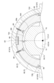
- FIG. 4 is a diagram showing an example of the arrangement of the bearing ring 24, pads 28, etc., when viewed axially from the direction P in FIG. 2.
- FIG. 5 is a diagram showing an example of the A-A cross section in FIG. 4.
- each of pads 28A to 28C includes a pad body portion 58 that includes a surface 28a that faces the outer peripheral surface 20a of the bearing 20 (see Figure 3), and an engagement portion 60 that protrudes radially outward from the pad body portion 58 and engages with the bearing ring 24.
- pads 28A to 28C have the same configuration, and in the following, a description that simply includes the description "pad 28" means a description common to pads 28A to 28C.
- the engagement portion 60 of the pad 28 protrudes radially outward from one axial end 61 of the pad body 58 and engages with the bearing ring 24.
- the pad 28 includes a circumferential abutment surface 60a (circumferential reference surface) that abuts against the bearing ring 24 in a direction along the circumferential direction, and the pad 28 is positioned in the circumferential direction by the circumferential abutment surface 60a abutting against the bearing ring 24.
- the inner circumferential surface 24b of the bearing ring 24 is formed with a number of recesses 62A, 62B, 62C spaced apart in the circumferential direction, into which the engagement portions 60 of the pads 28A to 28C are fitted.
- each of the recesses 62A to 62C is a groove formed at one end of the inner circumferential surface 24b of the bearing ring 24 in the axial direction. Note that the configurations of the recesses 62A to 62C are the same, and in the following description, any description that simply includes the term recess 62 means a description common to the recesses 62A to 62C.
- the pad 28 is positioned in the circumferential direction by the circumferential abutment surface 60a of the engagement portion 60 of the pad 28 abutting against the wall surface 62a on the downstream side in the rotation direction R of the rotor 12 among the inner surfaces of the recess 62 in the inner peripheral surface 24b of the bearing ring 24.
- the width W1 of the pad 28 in the direction perpendicular to each of the axial and radial directions is smaller than the width W2 of the recess 62 in the direction perpendicular to each of the axial and radial directions.
- the engagement portion 60 of the pad 28 includes an axial abutment surface 60b (axial reference surface) that abuts against the bearing ring 24 in the axial direction, and the axial abutment surface 60b abuts against a wall surface 62b on one axial side of the inner surface of the recess 62 of the bearing ring 24, thereby positioning the pad 28 in the axial direction.
- axial abutment surface 60b axial reference surface
- the radial depth D of the recess 62 in the bearing ring 24 is greater than the radial protrusion H of the engagement portion 60 from the pad body 58.
- H>t may be satisfied if the thickness of the liner 29 sandwiched between the pad 28 and the bearing ring 24 is t (however, if multiple liners 29 are sandwiched between one pad 28 and the bearing ring 24, the total thickness of the multiple liners) then H>t may be satisfied.
- the dimension of the gap g between the bearing 20 and the pads 28 (i.e., the gap between the bearing ring 24 and the bearing 20) can be easily adjusted by adjusting at least one of the thickness and the number of liners 29 sandwiched between the pads 28 provided on the inner diameter side of the bearing ring 24 and the inner peripheral surface 24b of the bearing ring 24.
- the circumferential abutment surface 60a of the engagement portion 60 abuts against the bearing ring 24 in the circumferential direction, thereby positioning the pad 28 in the axial direction. Therefore, even if the surface 20h of the bearing 20 facing the pad 28 and the surface 28a of the pad 28 facing the bearing 20 are each composed of a portion of a spherical surface, it is possible to suppress deviation in the circumferential position of the pad 28 relative to the bearing 20, thereby stabilizing the bearing performance.
- the axial abutment surface 60b of the engagement portion 60 abuts against the bearing ring 24 in the axial direction, thereby positioning the pad 28 in the axial direction. Therefore, even if the surface 20h of the bearing 20 facing the pad 28 and the surface 28a of the pad 28 facing the bearing 20 are each composed of a portion of a spherical surface, it is possible to suppress deviation in the axial position of the pad 28 relative to the bearing 20, thereby stabilizing the bearing performance.
- the circumferential abutment surface 60a abuts against a wall surface 62a on the inner surface of the recess 62 of the bearing ring 24, which is located downstream in the direction of rotation of the rotor 12. Therefore, even if the pad 28 is subjected to a load in the direction of rotation of the rotor 12, the wall surface 62a on the inner surface of the recess 62 of the bearing ring 24, which is located downstream in the direction of rotation of the rotor 12, can prevent the position of the pad 28 from shifting downstream in the direction of rotation of the rotor 12. Therefore, it is possible to effectively prevent deviation in the circumferential position of the pad 28 relative to the bearing 20, and stabilize the bearing performance.
- the inclined pads 28B, 28C can suppress the displacement of the bearing 20 and stabilize the bearing performance.
- FIG. 6 is a diagram showing an example of a cross section perpendicular to the axial direction of a part of the bearing device 8 shown in FIG. 6, the bearing device 8 includes a bearing 64, a bearing casing 65, a bearing ring 66, a plurality of pads 67, a plurality of liners 68, and a plurality of bolts 69. As shown in FIG 6, no insulating member is provided between the bearing 64 and the bearing casing 70 in the bearing device 8.
- the bearing 64 is configured to rotatably support the rotor 12 on the turbine 10 (see FIG. 1) side of the rotor 12 in the axial direction.
- the bearing 64 is configured in an annular shape to surround the shaft portion of the rotor 12, and is configured to be separable into an upper bearing half 74 and a lower bearing half 75 with a horizontal plane H3 including the central axis L3 of the bearing 64 as the boundary.
- the bearing casing 65 houses the bearing 64, the bearing ring 66, and a number of pads 67.
- the bearing casing 65 includes an end bracket (not shown) and a bearing cap 70 that is configured separately from the end bracket, and the bearing cap 70 is configured to be removable from the end bracket.
- the bearing cap 70 has a roughly semi-cylindrical shape and is provided above the horizontal plane H3 that includes the central axis L3 of the bearing 64.
- the bearing cap 70 is provided so as to cover the bearing 64 and the bearing ring 66 from above in the vertical direction.
- the bearing ring 66 is configured in an annular shape to surround the bearing 64, and is provided between the bearing casing 65 and the bearing 64.
- the bearing ring 66 is configured so that it can be divided into an upper half 76 of the bearing ring and a lower half (not shown) of the bearing ring, with the horizontal plane H4 including the central axis L4 of the bearing ring 66 as the boundary.
- Each of the multiple pads 67 is provided on the outer peripheral surface 66a of the bearing ring 66 and is held between the inner peripheral surface of the bearing cap 70 and the outer peripheral surface 66a of the bearing ring 66.
- the multiple pads 67 include a central pad 67A and a pair of horizontal pads 67B, 67C.
- the central pad 67A is provided at the top of the outer peripheral surface 66a of the bearing ring 66 so as to intersect with a vertical line LB perpendicular to the central axis L4 of the bearing ring 66.
- the horizontal pad 67B is located on or near a horizontal plane H4 including the central axis L4 of the bearing ring 66, and the horizontal pad 67C is located on the opposite side of the horizontal pad 67B across the rotor 12.
- multiple recesses 72A, 72B, and 72C are formed at intervals in the circumferential direction on the outer peripheral surface 66a of the bearing ring 66, and the pads 67A, 67B, and 67C are fitted into the recesses 72A, 72B, and 72C, respectively.
- the surface 64h of the bearing 64 facing the bearing ring 66 is formed of a part of a sphere, and the surface 66i of the bearing ring 66 facing the bearing 64 is formed of a part of a sphere.
- the multiple liners 68 include at least one liner 68A sandwiched between the outer peripheral surface 66a of the bearing ring 66 and the central pad 67A, at least one liner 68B sandwiched between the outer peripheral surface 66a of the bearing ring 66 and the horizontal pad 67B, and at least one liner 68C sandwiched between the outer peripheral surface 66a of the bearing ring 66 and the horizontal pad 67C.
- the bolts 69 are spaced apart in the circumferential direction and are configured to fasten the bearing ring 66 and the bearing cap 70.
- each of the bolts 69 extends radially from the inner circumferential surface side of the bearing ring 66 through the bearing ring 66 to the bearing cap 70.
- the bearing device 6 has an insulating member 26 between the bearing ring 24 and the bearing casing 22, and the bearing device 8 does not have an insulating member between the bearing ring 66 and the bearing casing 65.
- a pad 67 and a liner 72 can be provided between the bearing ring 66 and the bearing casing 65 of the bearing device 8, and the size of the gap between the bearing 64 and the bearing ring 66 can be easily adjusted by adjusting at least one of the thickness and the number of liners 72.
- the present disclosure is not limited to the above-described embodiments, and includes modifications to the above-described embodiments and appropriate combinations of these modifications.
- the arrangement of the bearing device 6 and the bearing device 8 may be reversed. That is, the bearing device 6 including the insulating member 26 may be configured to rotatably support the rotor on the turbine side of the generator 4, and the bearing device 8 not including the insulating member may be configured to rotatably support the rotor on the side of the generator 4 opposite to the turbine.
- the engagement portion 60 of the pad 28 is configured to protrude radially outward from the pad body 58 and engage with the recess 62 of the bearing ring 24, but in other embodiments, the engagement portion may be a recess formed on the radially outer surface of the pad body.
- the bearing ring may have a protrusion that protrudes radially inward from the inner peripheral surface of the bearing ring and is configured to engage with the recess of the pad body.
- the inner surface of the recess formed in the pad body may include a circumferential abutment surface that abuts against the bearing ring in a direction along the circumferential direction of the bearing ring, and an axial abutment surface that abuts against the bearing ring in the axial direction of the bearing ring.
- a generator bearing device (e.g., the above-described bearing device 6) has: a bearing (e.g., the bearing 20 described above) configured to rotatably support a rotor (e.g., the rotor 12 described above) of a generator (e.g., the generator 4 described above); A bearing casing (e.g., the above-mentioned bearing casing 22) that accommodates the bearing; A bearing ring (e.g., the above-mentioned bearing ring 24) provided between the bearing casing and the bearing; an insulating member (e.g., the insulating member 26 described above) provided between the outer peripheral surface of the bearing ring and the inner surface of the bearing casing; A first pad (e.g., the above-mentioned pad 28, 28A, 28B, or 28C) is provided on the inner diameter side of the bearing ring and arranged to face the outer circumferential surface of the bearing with a gap therebetween; a liner
- the size of the gap between the bearing ring and the bearing (i.e., the gap between the bearing and the pads) can be easily adjusted by adjusting at least one of the thickness and number of liners sandwiched between the pads provided on the inner diameter side of the bearing ring and the inner peripheral surface of the bearing ring. Therefore, even if it is not possible to provide pads between the outer peripheral surface of the bearing ring and the inner peripheral surface of the bearing casing because an insulating member for suppressing axial currents is provided between the outer peripheral surface of the bearing ring and the inner peripheral surface of the bearing casing, the size of the gap between the bearing and the bearing ring can be easily adjusted.
- the surface of the bearing facing the first pad (e.g., the surface 20h) is formed of a part of a spherical surface
- the surface of the first pad facing the bearing (e.g., the surface 28a) is formed of a part of a spherical surface
- the first pad includes an engagement portion (such as engagement portion 60 described above) that engages with the bearing ring.
- the surface of the bearing facing the first pad and the surface of the first pad facing the bearing are each formed of a portion of a sphere, even a slight deviation in the relative position of the first pad to the bearing can easily cause a significant decrease in bearing performance.
- an engagement portion where the first pad engages with the bearing ring as described in (2) above it is possible to suppress deviations in the relative position of the first pad to the bearing and stabilize bearing performance.
- the engaging portion includes an axial abutment surface (for example, the above-mentioned axial abutment surface 60b) that abuts against the bearing ring in the axial direction of the bearing ring.
- an axial abutment surface for example, the above-mentioned axial abutment surface 60b
- the axial abutment surface of the engagement portion abuts against the bearing ring in the axial direction of the bearing ring, thereby determining the position of the first pad in the axial direction of the bearing ring. Therefore, even if the surface of the bearing facing the first pad and the surface of the first pad facing the bearing are each composed of a portion of a sphere, it is possible to suppress deviation in the axial position of the first pad relative to the bearing, thereby stabilizing the bearing performance.
- the first pad includes a pad main body portion (for example, the above-mentioned pad main body portion 58) that faces the outer circumferential surface of the bearing, and the engagement portion is provided so as to protrude from the pad main body portion in the radial direction of the bearing ring.
- a pad main body portion for example, the above-mentioned pad main body portion 58
- the position of the first pad in the axial direction of the bearing ring is determined by the axial abutment surface provided on the engagement portion that protrudes from the pad main body in the radial direction of the bearing ring abutting against the bearing ring in the axial direction. Therefore, even if the surface of the bearing facing the first pad and the surface of the first pad facing the bearing are each composed of a portion of a sphere, it is possible to suppress deviation in the axial position of the first pad relative to the bearing, and stabilize the bearing performance.
- the engaging portion includes a circumferential contact surface (for example, the above-mentioned circumferential contact surface 60a) that contacts the bearing ring in a direction along the circumferential direction of the bearing ring.
- a circumferential contact surface for example, the above-mentioned circumferential contact surface 60a
- the circumferential abutment surface of the engagement portion abuts against the bearing ring in a direction along the circumferential direction of the bearing ring, thereby determining the position of the first pad in the circumferential direction of the bearing ring. Therefore, even if the surface of the bearing facing the first pad and the surface of the first pad facing the bearing are each composed of a portion of a sphere, it is possible to suppress deviation in the circumferential position of the first pad relative to the bearing, thereby stabilizing the bearing performance.
- a recess (e.g., the recess 62A, 62B, or 62C) is formed on the inner circumferential surface of the bearing ring, The circumferential abutment surface abuts against an inner surface of the recess of the bearing ring.
- the circumferential abutment surface of the engagement portion abuts against the inner surface of the recess of the bearing ring in a direction along the circumferential direction of the bearing ring, thereby determining the position of the first pad in the circumferential direction of the bearing ring. Therefore, even if the surface of the bearing facing the first pad and the surface of the first pad facing the bearing are each composed of a portion of a sphere, it is possible to suppress deviation in the circumferential position of the first pad relative to the bearing, thereby stabilizing the bearing performance.
- the circumferential contact surface abuts against a wall surface (for example, the above-mentioned wall surface 62a) on the inner surface of the recess of the bearing ring, the wall surface being on the downstream side in the rotation direction of the rotor.
- the downstream wall surface of the inner surface of the recess of the bearing ring prevents the position of the first pad from shifting downstream in the direction of rotation of the rotor. This effectively prevents the first pad from shifting relative to the bearing in the circumferential direction, stabilizing the bearing performance.
- a pair of inclined pads (e.g., the inclined pads 28B and 28C) are provided on the inner peripheral surface of the bearing ring and arranged to face each other across a gap on the outer peripheral surface of the bearing;
- a liner (e.g., the above-mentioned liner 29B, 29C) sandwiched between the inner peripheral surface of the bearing ring and each of the pair of inclined pads; Further comprising: The first pad is disposed between the pair of oblique pads in the circumferential direction of the bearing ring.
- the inclined pad can suppress bearing displacement and stabilize bearing performance.
- a generator bearing device configured to at least one embodiment of the present disclosure, A first bearing device (e.g., the above-mentioned bearing device 6) configured to rotatably support one end side of a rotor of a generator; A second bearing device (e.g., the above-mentioned bearing device 8) configured to rotatably support the other end side of the rotor; Equipped with The first bearing device is a generator bearing device according to any one of (1) to (8) above, The second bearing device is A bearing (e.g., the above-mentioned bearing 64) configured to rotatably support the other end side of the rotor of the generator; a bearing casing (e.g., the above-mentioned bearing casing 65) that accommodates the bearing of the second bearing device; A bearing ring (e.g., the above-mentioned bearing ring 66) provided between the bearing casing of the second bearing device and the bearing of the second bearing device; a pad (e.g., the above-menti
- the first bearing device has an insulating member between the outer circumferential surface of the bearing ring and the inner surface of the bearing casing
- the second bearing device does not have an insulating member between the outer circumferential surface of the bearing ring and the inner surface of the bearing casing. Therefore, for the second bearing device, pads and liners can be provided between the outer circumferential surface of the bearing ring of the second bearing device and the inner surface of the bearing casing of the second bearing device, and the size of the gap between the bearing and the pads can be easily adjusted by adjusting at least one of the thickness and number of liners.
- a turbine power generation system according to at least one embodiment of the present disclosure, The power generating device according to (9) above, a turbine (e.g., turbine 10 described above) coupled to the rotor of the generator; Equipped with The first bearing device is configured to support the rotor on an axial side of the generator opposite the turbine.
- a turbine e.g., turbine 10 described above
- an insulating member is provided between the outer peripheral surface of the bearing ring and the inner surface of the bearing casing in the first bearing device that supports the rotor on the side of the rotor opposite the turbine in the axial direction of the generator. Therefore, as described in (10) above, by using the generating device described in (9) above in such a typical turbine generating system, it is possible to easily adjust the size of the gap between the bearing and the pad while suppressing the axial current with a simple configuration.
Landscapes
- Engineering & Computer Science (AREA)
- Power Engineering (AREA)
- Sliding-Contact Bearings (AREA)
Priority Applications (2)
| Application Number | Priority Date | Filing Date | Title |
|---|---|---|---|
| JP2025544008A JPWO2025052558A1 (https=) | 2023-09-06 | 2023-09-06 | |
| PCT/JP2023/032442 WO2025052558A1 (ja) | 2023-09-06 | 2023-09-06 | 発電機用軸受装置、発電装置及びタービン発電システム |
Applications Claiming Priority (1)
| Application Number | Priority Date | Filing Date | Title |
|---|---|---|---|
| PCT/JP2023/032442 WO2025052558A1 (ja) | 2023-09-06 | 2023-09-06 | 発電機用軸受装置、発電装置及びタービン発電システム |
Publications (1)
| Publication Number | Publication Date |
|---|---|
| WO2025052558A1 true WO2025052558A1 (ja) | 2025-03-13 |
Family
ID=94923023
Family Applications (1)
| Application Number | Title | Priority Date | Filing Date |
|---|---|---|---|
| PCT/JP2023/032442 Pending WO2025052558A1 (ja) | 2023-09-06 | 2023-09-06 | 発電機用軸受装置、発電装置及びタービン発電システム |
Country Status (2)
| Country | Link |
|---|---|
| JP (1) | JPWO2025052558A1 (https=) |
| WO (1) | WO2025052558A1 (https=) |
Citations (7)
| Publication number | Priority date | Publication date | Assignee | Title |
|---|---|---|---|---|
| JPS5224645A (en) * | 1975-08-20 | 1977-02-24 | Hitachi Ltd | Sliding movement bearing device |
| JPS52171611U (https=) * | 1976-06-19 | 1977-12-27 | ||
| JPS5364206U (https=) * | 1976-10-27 | 1978-05-30 | ||
| JPS5835010U (ja) * | 1981-08-31 | 1983-03-07 | 三菱電機株式会社 | 球面支持された軸受の位置決め装置 |
| JPS58196417U (ja) * | 1982-06-25 | 1983-12-27 | 石川島播磨重工業株式会社 | ガス軸受構造 |
| JPS63190615U (https=) * | 1987-05-29 | 1988-12-08 | ||
| JPH07505945A (ja) * | 1992-04-24 | 1995-06-29 | アイド、ラセル ディー. | 可変の剛性および減衰率をもつ流体減衰支持装置 |
-
2023
- 2023-09-06 WO PCT/JP2023/032442 patent/WO2025052558A1/ja active Pending
- 2023-09-06 JP JP2025544008A patent/JPWO2025052558A1/ja active Pending
Patent Citations (7)
| Publication number | Priority date | Publication date | Assignee | Title |
|---|---|---|---|---|
| JPS5224645A (en) * | 1975-08-20 | 1977-02-24 | Hitachi Ltd | Sliding movement bearing device |
| JPS52171611U (https=) * | 1976-06-19 | 1977-12-27 | ||
| JPS5364206U (https=) * | 1976-10-27 | 1978-05-30 | ||
| JPS5835010U (ja) * | 1981-08-31 | 1983-03-07 | 三菱電機株式会社 | 球面支持された軸受の位置決め装置 |
| JPS58196417U (ja) * | 1982-06-25 | 1983-12-27 | 石川島播磨重工業株式会社 | ガス軸受構造 |
| JPS63190615U (https=) * | 1987-05-29 | 1988-12-08 | ||
| JPH07505945A (ja) * | 1992-04-24 | 1995-06-29 | アイド、ラセル ディー. | 可変の剛性および減衰率をもつ流体減衰支持装置 |
Also Published As
| Publication number | Publication date |
|---|---|
| JPWO2025052558A1 (https=) | 2025-03-13 |
Similar Documents
| Publication | Publication Date | Title |
|---|---|---|
| US9030071B2 (en) | Electrical machines | |
| WO2020082960A1 (zh) | 一种燃气轮机发电机组 | |
| JP7063637B2 (ja) | 回転電機のロータ | |
| US20200032845A1 (en) | Active radial magnetic bearing assembly with internal sensors | |
| CA2864041A1 (en) | Roller bearing set and corresponding rotating machine | |
| JP5705259B2 (ja) | 回転電機のステータコア固定構造 | |
| TWI687028B (zh) | 馬達構造 | |
| US12206311B2 (en) | Outer diameter side magnet field and magnetic gear | |
| JP5497489B2 (ja) | 遠心型圧縮機 | |
| JP6550947B2 (ja) | 回転機械 | |
| WO2025052558A1 (ja) | 発電機用軸受装置、発電装置及びタービン発電システム | |
| CN110431730B (zh) | 发电机的承载鞍组件和轴端发电机组件 | |
| JP2020115730A (ja) | 回転電機のロータ | |
| CA2940967A1 (en) | Rotary machine having magnetic and mechanical bearings | |
| US10944307B2 (en) | Rotary electric machine, generator, and wind turbine power generation facility | |
| WO2018142441A1 (ja) | アキシャルギャップ型回転電機 | |
| WO2017122289A1 (ja) | 回転電機および加振装置 | |
| JP6148209B2 (ja) | 回転電機用ロータ | |
| JP2020089205A (ja) | 回転軸の支持構造 | |
| JP2024153492A (ja) | モータ、モータの製造方法、モータを備えるドローン | |
| JP6715585B2 (ja) | モータ | |
| JP6563235B2 (ja) | 回転電機の回転子の絶縁スペーサ | |
| CN203774949U (zh) | 防震型外转子马达 | |
| JP2017011930A (ja) | 回転電機及び回転電機の製造方法 | |
| JPH0628507B2 (ja) | 回転機械の気密継手装置 |
Legal Events
| Date | Code | Title | Description |
|---|---|---|---|
| 121 | Ep: the epo has been informed by wipo that ep was designated in this application |
Ref document number: 23951461 Country of ref document: EP Kind code of ref document: A1 |
|
| ENP | Entry into the national phase |
Ref document number: 2025544008 Country of ref document: JP Kind code of ref document: A |
|
| WWE | Wipo information: entry into national phase |
Ref document number: 2025544008 Country of ref document: JP |