WO2025047958A1 - ガスシールドアーク溶接用ソリッドワイヤ、及び溶接継手の製造方法 - Google Patents
ガスシールドアーク溶接用ソリッドワイヤ、及び溶接継手の製造方法 Download PDFInfo
- Publication number
- WO2025047958A1 WO2025047958A1 PCT/JP2024/031293 JP2024031293W WO2025047958A1 WO 2025047958 A1 WO2025047958 A1 WO 2025047958A1 JP 2024031293 W JP2024031293 W JP 2024031293W WO 2025047958 A1 WO2025047958 A1 WO 2025047958A1
- Authority
- WO
- WIPO (PCT)
- Prior art keywords
- solid wire
- wire
- less
- content
- arc welding
- Prior art date
- Legal status (The legal status is an assumption and is not a legal conclusion. Google has not performed a legal analysis and makes no representation as to the accuracy of the status listed.)
- Pending
Links
Images





Classifications
-
- B—PERFORMING OPERATIONS; TRANSPORTING
- B23—MACHINE TOOLS; METAL-WORKING NOT OTHERWISE PROVIDED FOR
- B23K—SOLDERING OR UNSOLDERING; WELDING; CLADDING OR PLATING BY SOLDERING OR WELDING; CUTTING BY APPLYING HEAT LOCALLY, e.g. FLAME CUTTING; WORKING BY LASER BEAM
- B23K35/00—Rods, electrodes, materials, or media, for use in soldering, welding, or cutting
- B23K35/22—Rods, electrodes, materials, or media, for use in soldering, welding, or cutting characterised by the composition or nature of the material
- B23K35/24—Selection of soldering or welding materials proper
- B23K35/30—Selection of soldering or welding materials proper with the principal constituent melting at less than 1550°C
- B23K35/3053—Fe as the principal constituent
-
- B—PERFORMING OPERATIONS; TRANSPORTING
- B23—MACHINE TOOLS; METAL-WORKING NOT OTHERWISE PROVIDED FOR
- B23K—SOLDERING OR UNSOLDERING; WELDING; CLADDING OR PLATING BY SOLDERING OR WELDING; CUTTING BY APPLYING HEAT LOCALLY, e.g. FLAME CUTTING; WORKING BY LASER BEAM
- B23K35/00—Rods, electrodes, materials, or media, for use in soldering, welding, or cutting
- B23K35/02—Rods, electrodes, materials, or media, for use in soldering, welding, or cutting characterised by mechanical features, e.g. shape
- B23K35/0255—Rods, electrodes, materials, or media, for use in soldering, welding, or cutting characterised by mechanical features, e.g. shape for use in welding
- B23K35/0261—Rods, electrodes or wires
-
- B—PERFORMING OPERATIONS; TRANSPORTING
- B23—MACHINE TOOLS; METAL-WORKING NOT OTHERWISE PROVIDED FOR
- B23K—SOLDERING OR UNSOLDERING; WELDING; CLADDING OR PLATING BY SOLDERING OR WELDING; CUTTING BY APPLYING HEAT LOCALLY, e.g. FLAME CUTTING; WORKING BY LASER BEAM
- B23K35/00—Rods, electrodes, materials, or media, for use in soldering, welding, or cutting
- B23K35/22—Rods, electrodes, materials, or media, for use in soldering, welding, or cutting characterised by the composition or nature of the material
- B23K35/24—Selection of soldering or welding materials proper
- B23K35/30—Selection of soldering or welding materials proper with the principal constituent melting at less than 1550°C
-
- B—PERFORMING OPERATIONS; TRANSPORTING
- B23—MACHINE TOOLS; METAL-WORKING NOT OTHERWISE PROVIDED FOR
- B23K—SOLDERING OR UNSOLDERING; WELDING; CLADDING OR PLATING BY SOLDERING OR WELDING; CUTTING BY APPLYING HEAT LOCALLY, e.g. FLAME CUTTING; WORKING BY LASER BEAM
- B23K9/00—Arc welding or cutting
- B23K9/16—Arc welding or cutting making use of shielding gas
- B23K9/173—Arc welding or cutting making use of shielding gas and of a consumable electrode
Definitions
- the present disclosure relates to a solid wire for gas shielded arc welding and a method for producing a welded joint.
- Gas-shielded arc welding is widely used in a variety of fields. For example, in the automotive field, gas-shielded arc welding is used to weld suspension components and the like.
- a welding material for gas-shielded arc welding is solid wire.
- Solid wire is a wire that does not have flux in the center of the wire cross section, and its cross section is solid.
- Various solid wires for gas-shielded arc welding have been proposed in the prior art.
- Patent Document 1 discloses a gas-shielded arc welding wire containing, per total mass of the wire, C: 0.01% to 0.10%, Si: 0.05% to 0.55%, Mn: 1.60% to 2.40%, Ti: 0.05% to 0.25%, Cu: 0.30% or less, Al: 0.10% or less, P: 0.025% or less, S: 0.010% or less, the balance being Fe and unavoidable impurities, where the Si content (percent by mass) per total mass of the wire is [Si] and the Ti content (percent by mass) per total mass of the wire is [Ti], and the relationship is 0.1 ⁇ [Ti]/[Si] ⁇ 3.0.
- Patent Document 2 discloses an extremely low-silicon welding wire with excellent porosity resistance and electrocoatability, which contains, by weight, C: 0.001-0.30%, Si: 0.15% or less, Mn: 0.50-3.00%, P: 0.030% or less, S: 0.030% or less, the balance being Fe and unavoidable impurities.
- solid wire with reduced Si content impairs welding workability. Specifically, solid wire with reduced Si content increases spatter and impairs gap weldability in lap welding.
- Spatter is molten metal particles that fly off during arc welding. Spatter impairs the workability of welding. Some of the spatter that flies off into the welding work environment adheres to the surface of the welded joint, marring the aesthetics of the welded joint. Spatter that adheres to the surface of the welded joint can also become the starting point for fatigue cracks or the starting point for red rust caused by poor electrocoating. The process of removing spatter that has adhered to the welded joint increases the manufacturing cost of the welded joint.
- Gap weldability is the ability to form a normal joint when welding multiple overlapping steel plates. In actual welding work, gaps often occur between the steel plates at the weld due to variations in press quality and assembly accuracy. In lap fillet joints, which are often used in arc welding of thin steel plates, the shape of the weld connecting the upper and lower plates is easily disturbed when the gap between the steel plates increases. In joints with a weld shape as shown in FIG. 3B, sufficient joint strength may not be obtained. When welding a plate assembly with a gap S between the upper and lower plates, a solid wire that cannot form the weld metal 1 up to the upper end of the upper plate end surface is evaluated as having low gap weldability.
- the weld metal 1 may slip into the gap S of the steel plate 2, or an undercut A may occur in the lower plate (the steel plate 2 on the lower side of the paper whose surface is welded).
- FIG. 3A when welding a plate assembly having a plate gap S between an upper plate and a lower plate, a solid wire that can obtain a weld (weld joint) in which the end face of the upper plate is entirely melted and the weld metal 1 is formed up to the corner of the upper plate is evaluated as having high plate gap weldability.
- Solid wire is obtained by drawing wire material. The more alloying elements are added to the wire material in order to increase the amount of alloying elements in the solid wire, the more difficult it becomes to draw the wire material.
- Patent Document 1 aims to improve the sputter resistance of solid wire and the electrocoatability of welded joints obtained using solid wire. However, Patent Document 1 does not consider the gap weldability or manufacturability of solid wire. Patent Document 2 aims to improve the gap weldability of welded joints obtained using solid wire. However, Patent Document 2 does not consider the sputter resistance, gap weldability, or manufacturability of solid wire.
- the objective of this disclosure is to provide a solid wire for gas-shielded arc welding that can prevent welding defects in plate assemblies with large gaps, and that can produce welded joints that have excellent wire drawing processability during wire production and are highly suitable for electrochemical coating, as well as a method for producing the welded joints.
- the gist of this disclosure is as follows:
- a solid wire for gas shielded arc welding has, in mass % with respect to a total mass of the solid wire, C: 0.04 to 0.12%, Si: 0.13 to 0.28%, Mn: 1.4 to 2.3%, Ti: 0.13 to 0.25%, Al: 0.001 to 0.050%, Cr: 0 to 3.00%, Ni: 0 to 3.00%, P: 0.020% or less, S: 0.015% or less, N: 0.
- the solid wire for gas-shielded arc welding according to the above (1) has, in mass % with respect to the total mass of the solid wire, The formula (vi) is satisfied: 0.16 ⁇ C ⁇ (5 ⁇ Si+Mn) ⁇ 0.35 (vi).
- the solid wire for gas shielded arc welding according to (1) or (2) above contains, in mass % relative to the total mass of the solid wire, one or more selected from Al: 0.010 to 0.050%, Cr: 0.10 to 1.50%, Ni: 0.10 to 3.00%, and B: 0.0030 to 0.0100%.
- a hardness measured at a cross section of the solid wire satisfies the following formulas (vii) and (viii): H2 ⁇ 250 (vii) H2 ⁇ H1 ⁇ 40 (viii)
- the symbol H1 in the formula (viii) is the Vickers hardness measured at a depth of 0.05 mm from the surface of the solid wire
- the symbol H2 in the formulas (vii) and (viii) is the average value of the Vickers hardness measured at depths of 0.25 mm and 0.35 mm from the surface.
- the solid wire for gas shielded arc welding according to any one of (1) to (4) above preferably contains, in mass % relative to the total mass of the solid wire, 0.13 to 0.19% Si.
- Cr is 0.15 to 3.00% by mass based on the total mass of the solid wire.
- Cr is 0% or more and less than 0.50%, in terms of mass% with respect to the total mass of the solid wire.
- the solid wire for gas-shielded arc welding preferably contains, in mass % relative to the total mass of the solid wire, Ni: 0 to 0.45%.
- the solid wire for gas-shielded arc welding according to any one of (1) to (8) above has, in mass % relative to the total mass of the solid wire, 0.05 ⁇ Cr+Ni ⁇ 3.00 (ix) is satisfied.
- the solid wire for gas shielded arc welding according to any one of (1) to (9) above has a diameter of 0.8 to 1.4 mm.
- a method for manufacturing a welded joint according to another aspect of the present disclosure includes a step of gas-shielded arc welding a steel plate using a solid wire for gas-shielded arc welding described in any one of (1) to (10) above.
- the present disclosure provides a solid wire for gas-shielded arc welding that can prevent welding defects in plate assemblies with large gaps, has excellent wire drawing processability during wire production, and can produce welded joints that are highly suitable for electrochemical coating, as well as a method for producing the welded joints.
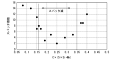
- 1 is a graph showing the results of an experiment investigating the relationship between Si+0.5 ⁇ (Mn+Cr)+0.3 ⁇ Ni and gap weldability. 1 is a graph showing the results of an experiment investigating the relationship between C ⁇ (5 ⁇ Si+Mn) and the amount of sputtering.
- 1 is a cross-sectional view of an example of a weld obtained by using a solid wire having high gap weldability.
- FIG. 2 is a cross-sectional view of an example of a weld obtained by using a solid wire with poor gap weldability.
- FIG. 2 is a schematic diagram showing a gap between steel plates for evaluating plate gap weldability.
- FIG. 2 is a schematic diagram showing the transfer state of droplets from the tip of a solid wire having poor droplet transfer characteristics.
- FIG. 2 is a schematic diagram showing the transfer state of droplets from the tip of a solid wire having high droplet transfer characteristics.
- 1 is a graph showing examples of cross-sectional hardness of various welding wires.
- a numerical range expressed using “ ⁇ ” means a range that includes the numerical values written before and after " ⁇ ” as the lower and upper limits. However, when the numerical values written before and after " ⁇ " are followed by "more than” or “less than,” the numerical range means a range that does not include these numerical values as the lower or upper limit.
- the present inventors have conducted extensive research into ways to solve the electrodeposition coating problem and have obtained the following findings.
- A The Si content of the solid wire is reduced as much as possible, and the generation of Si-based slag is suppressed, thereby improving the electrodeposition paintability. In a component system with a small Si content, the degree of deterioration of the electrodeposition paintability due to Mn slag is small.
- B By controlling the Ti content of the solid wire within an appropriate range, conductive Ti-based slag is generated on the surface of the weld bead, improving the electrodeposition paintability.
- C By controlling the Ti and Al contents of the solid wire within appropriate ranges, the generation of insulating Si, Mn-based slag is suppressed, improving the electrodeposition paintability.
- the inventors believed that the heat input balance for melting the welding wire, along with the high-temperature physical properties of the weld metal, such as viscosity and surface tension, which are caused by the components of the molten metal, affect gap weldability.
- the inventors focused on this heat input balance and investigated the effect of the electrical resistance of the solid wire on the heat input balance.
- the solid wire melts and the molten metal transfers from the tip of the solid wire to the steel plate.
- the amount of heat required to melt the solid wire comes from the resistance heating generated by the current flowing through the solid wire and the arc plasma generated between the solid wire and the steel plate. If the Si content of the solid wire is reduced, the electrical resistance of the solid wire decreases, and the amount of resistance heating decreases. As a result, the solid wire does not melt sufficiently. If the welding current value is increased in order to ensure the amount of heat required to melt the solid wire, the amount of heat generated in the steel plate and molten metal increases, and the molten metal becomes overheated. It was thought that this would promote burn-through at the weld.
- formula (3) 1.00 ⁇ Si+0.5 ⁇ (Mn+Cr)+0.3 ⁇ Ni (3)
- the "Si+0.5 ⁇ (Mn+Cr)+0.3 ⁇ Ni" in formula (3) is an index of the electrical resistance of the solid wire.
- Mn, Cr, and Ni, like Si, have the function of increasing the electrical resistance of steel.
- Figure 1 shows the results of the inventors' experiments on the effect of formula (3).
- the inventors performed gas-shielded arc welding under the same conditions using multiple solid wires with different Si+0.5 ⁇ (Mn+Cr)+0.3 ⁇ Ni. They then investigated the plate gap (gap between steel plates) at which these solid wires can be welded. Specifically, lap fillet welding was performed on a plate assembly in which the gap between steel plates 2 gradually widens as shown in Figure 4, and the limit value of the plate gap at which a good weld can be obtained as shown in Figure 3A was determined.
- a "good weld” means a weld in which weld metal 1 is formed up to the top end of the upper plate end surface.
- Figure 1 is a graph with the horizontal axis representing the solid wire's Si+0.5 ⁇ (Mn+Cr)+0.3 ⁇ Ni, and the vertical axis representing the upper limit weld gap (i.e., the upper limit gap at which a good weld joint can be obtained). As shown in Figure 1, it was found that good gap weldability can be ensured by making the solid wire Si+0.5 ⁇ (Mn+Cr)+0.3 ⁇ Ni 1.00% or more.
- Spatter reduction during welding can be achieved by optimizing welding conditions, such as increasing the welding voltage.
- increasing the welding voltage increases the welding heat input, which can lead to reduced gap weldability and burn-through (holes) in the steel plate. For this reason, it is preferable to reduce spatter by improving the welding wire.
- the inventors conducted extensive research into the causes of spattering by observing the behavior of molten metal during gas-shielded arc welding with a high-speed camera. As a result, they discovered that droplet transfer becomes unstable when using solid wire with reduced silicon to improve electrocoatability.
- a droplet is a granular drop of molten metal formed when the tip of the wire melts due to heat from an arc or the like. Droplet transfer is the phenomenon in which droplets move from the consumable electrode toward the molten pool as they pass through the arc generation area.
- gas shielded arc welding employs pulsed MAG welding, which periodically varies the welding current value.
- pulsed MAG welding the ideal droplet transfer phenomenon is when droplets form at the tip of the solid wire when the welding current value increases, and when the welding current value decreases, the droplets separate from the tip of the solid wire. In other words, it is preferable for the droplet transfer cycle and the increase/decrease cycle of the welding current value to match.
- the inventors have found that the lower the Si content of the solid wire, the more difficult it is for droplets to separate from the tip of the solid wire. When droplets become difficult to separate from the tip of the solid wire, it becomes difficult for the droplet transfer cycle and the increase/decrease cycle of the welding current value to coincide. The inventors have found that when these two cycles are misaligned, spatter occurs.
- the droplets 5 will separate into spherical particles as shown in Figure 5B, improving the droplet transfer characteristics.
- the inventors therefore focused on viscosity, another factor affecting droplet separation characteristics. That is, by incorporating appropriate amounts of Si and Mn into the solid wire 4, deoxidization of the droplets 5 is promoted, thereby increasing the surface tension of the droplets 5. Furthermore, by incorporating an appropriate amount of C into the solid wire 4, the viscosity of the droplets 5 is reduced, thereby increasing the fluidity of the droplets.
- the inventors attempted to promote stable droplet separation as shown in Figure 5B by using the synergistic effect of these actions.
- Figure 2 shows the results of the inventors' experiments on the effect of formula (6).
- the inventors performed gas shielded arc welding under the same conditions using multiple solid wires with different C x (5 x Si + Mn). They then counted the number of spatter particles adhering to the surface of the steel plate.
- Figure 2 is a graph with the C x (5 x Si + Mn) of the solid wire on the horizontal axis and the number of spatter particles adhering to the surface of the steel plate on the vertical axis.
- the amount of spatter could be significantly reduced by using a solid wire with C x (5 x Si + Mn) in the range of 0.16 or more and 0.35 or less.
- the solid wire with reduced Si content needs to contain alloying elements to increase the electrical resistance and reduce the viscosity of the molten droplets.
- the solid wire needs to contain Ti.
- these alloying elements increase the hardness of the solid wire and the wire material from which the solid wire is made. The harder the wire, the more likely it is to break when drawing the wire to obtain the solid wire.
- the inventors decided to further control the chemical composition of the solid wire by the following formula (4). 0.30 ⁇ C+Mn/6+Si/24+Ni/40+Cr/5+Mo/4+V/14 ⁇ 0.55... (4)
- the "C+Mn/6+Si/24+Ni/40+Cr/5+Mo/4+V/14" in formula (4) is the carbon equivalent Ceq.
- Ceq is set to 0.55 mass% or less. This makes it difficult for breakage to occur during drawing of the solid wire, improving the manufacturability of the solid wire.
- a solid wire can be obtained that is easy to manufacture, can avoid welding defects in plate assemblies with large gaps, and can produce welded joints with high electrocoatability.
- the solid wire can have a spatter suppression effect.
- the solid wire for gas-shielded arc welding according to this embodiment achieves its effects through the synergistic effects of each component composition alone and when they coexist, and the reasons for limiting each component composition are described below.
- All alloying element contents described below are in mass% relative to the total mass of the solid wire. If the solid wire has a plating layer such as copper plating, the mass of the alloying element contained in the entire solid wire including the plating layer divided by the total mass of the solid wire including the plating layer is the mass% of that alloying element relative to the total mass of the solid wire.
- mass% relative to the total mass of the solid wire will be simply referred to as “%”.
- the unit “mass%” of carbon equivalent Ceq will also be simply referred to as "%”.
- C is an element that increases the strength of the weld metal. By making the C content 0.04% or more, the strength of the weld metal can be improved. In addition, C has the effect of reducing the viscosity of droplets formed by melting the solid wire. This stabilizes the droplet transfer and suppresses the amount of spatter. By making the C content 0.04% or more, the above-mentioned effects can be obtained. Furthermore, it is preferable that the C content be 0.06% or more.
- the C content should be 0.12% or less. Furthermore, it is preferable that the C content be 0.10% or less.
- Silicon in solid wire is an element that has a deoxidizing effect, and during gas-shielded arc welding, it combines with oxygen in the molten pool to form slag. When the molten pool solidifies to form the weld metal, the slag is expelled from the weld metal. Therefore, silicon has the effect of reducing the amount of oxygen in the weld metal. Silicon is actively added to ordinary solid wires as a deoxidizing element.
- the Si content of the solid wire is set to 0.28% or less. It is preferable to set the Si content to 0.25% or less, 0.22% or less, 0.20% or less, 0.19% or less, or 0.18% or less.
- the Si content of the solid wire is excessively reduced, the electrical resistance of the solid wire becomes insufficient. The lower the electrical resistance of the solid wire, the more difficult it becomes to melt the solid wire, and the worse the gap weldability becomes.
- the Si content of the solid wire is excessively reduced, the surface tension of the droplets formed by melting the solid wire decreases, the droplet transfer becomes unstable, and the amount of spatter increases.
- the adverse effects of reducing Si are mitigated by using elements other than Si so as to satisfy formula (3) and preferably formula (6).
- the Si content is set to 0.13% or more. If necessary, the Si content may be set to 0.15% or more, 0.18% or more, or 0.20% or more.
- Mn is also a deoxidizing element. Mn promotes the deoxidation of the molten pool during arc welding. Furthermore, Mn also has the effect of improving the tensile strength of the weld metal. In addition, Mn also has the effect of promoting resistance heating of the solid wire and improving the gap weldability. Mn also has the effect of increasing the surface tension through the deoxidizing action of the droplets, thereby stabilizing the droplet transfer. Therefore, the Mn content of the solid wire is set to 1.4% or more. The Mn content is preferably 1.5% or more, 1.6% or more, 1.7% or more, or 1.8% or more.
- the Mn content of the solid wire is 2.3% or less.
- the Mn content is preferably 2.2% or less, 2.1% or less, or 2.0% or less.
- Ti 0.13-0.25%
- Ti-based slag mainly composed of Ti oxides.
- Ti-based slag is conductive, unlike Si, Mn-based slag.
- Conductive Ti-based slag is less likely to cause electrodeposition coating defects. Therefore, Ti can improve the electrodeposition coating properties of solid wire.
- Ti also has the effect of suppressing the occurrence of blowholes.
- the Ti content of the solid wire is set to 0.13% or more. The Ti content is preferably set to 0.15% or more, 0.18% or more, or 0.20% or more.
- the Ti content should be 0.25% or less. It is preferable that the Ti content be 0.24% or less, 0.23% or less, or 0.21% or less.
- Al has a deoxidizing effect. Al promotes the deoxidation of the molten pool, thereby improving the tensile strength of the weld metal. Similarly to Ti, Al can reduce the amount of Si, Mn-based slag produced and improve the electrodeposition paintability. Therefore, the Al content of the solid wire is 0.001% or more. The Al content is preferably 0.010% or more, 0.015% or more, or 0.018% or more.
- the Al content of the solid wire is 0.050% or less. It is preferable that the Al content be 0.030% or less, or 0.020% or less.
- the lower limit of the Cr content is 0%
- the lower limit of the Ni content is 0%
- the lower limit of the total content of Cr and Ni is also 0%.
- the solid wire preferably contains at least one of Cr and Ni.
- both Cr and Ni are contained in the solid wire.
- the total content of Cr and Ni is preferably 0.05% or more. It is more preferable that the total content of Cr and Ni is 0.10% or more, 0.15% or more, or 0.30% or more.
- the total content of Cr and Ni is 3.00% or less. It is preferable that the total content of Cr and Ni is 2.50% or less, 2.00% or less, or 1.00% or less.
- the solid wire satisfies equation (5). 0 ⁇ Cr+Ni ⁇ 3.00 ... (5)
- the element symbols in formula (5) represent the content of each element in mass% with respect to the total mass of the solid wire.
- the values on the left and right sides of formula (5) can be replaced with the above-mentioned preferable upper and lower limit values of the total content of Cr and Ni.
- the solid wire may satisfy formula (9) instead of formula (5). 0.05 ⁇ Cr+Ni ⁇ 3.00...Formula (9)
- the Cr content is 0-3.00%.
- the Cr content may be specified as 0.05-1.50%.
- the Cr content is preferably 0.05% or more, 0.11% or more, 0.15% or more, or 0.20% or more.
- the Cr content is preferably 2.50% or less, 2.00% or less, 1.50% or less, 1.20% or less, 1.00% or less, 0.50% or less, less than 0.50%, 0.45% or less, or 0.40% or less.
- Ni 0-3.00%
- the Ni content is set to 0 to 3.00%.
- the Ni content may be specified to be 0.05 to 3.00%.
- the Ni content is preferably 0.05% or more, 0.08% or more, 0.10% or more, or 0.20% or more.
- the Ni content is preferably 2.50% or less, 2.00% or less, 1.50% or less, 1.20% or less, 1.00% or less, 0.50% or less, 0.45% or less, or 0.40% or less.
- P is an element that is generally mixed as an impurity in steel, and is also usually contained as an impurity in solid wire for arc welding. Since P is one of the main elements that cause hot cracking in weld metal, it is desirable to suppress its content as much as possible. If the P content exceeds 0.020%, hot cracking in weld metal becomes significant. Therefore, the P content of the solid wire is 0.020% or less. The P content is preferably 0.015% or less, 0.012% or less, or 0.010% or less.
- the P content of the solid wire may be 0%. However, taking into account refining costs, the P content of the solid wire may be more than 0%. The P content may be 0.001% or more, 0.002% or more, or 0.005% or more.
- S is an element that is generally mixed into steel as an impurity, and is also usually contained as an impurity in solid wire for arc welding. Therefore, the S content of the solid wire is 0.015% or less.
- the S content is preferably 0.012% or less, 0.010% or less, or 0.008% or less.
- the S content may be 0%, but may be more than 0% or 0.001% or more in consideration of refining costs.
- N is also an element that is generally mixed as an impurity in steel, and is also usually contained as an impurity in solid wire for arc welding. Excessive N reduces the toughness of the weld metal and causes porosity defects in the weld metal. Therefore, the N content of the solid wire is set to 0.006% or less. The N content is preferably set to 0.005% or less, or 0.004% or less. The N content may be 0%, but may be set to more than 0% or 0.001% or more in consideration of refining costs.
- Mo, B, Cu, Nb, and V are not essential elements for solving the problems of this disclosure. Therefore, the lower limit of the content of these elements is 0%. On the other hand, by including one or more of these elements in the solid wire, the performance of the solid wire can be further improved.
- the Mo content of the solid wire may be 0%. However, since Mo enhances the hardenability of the welded portion and improves the tensile strength, the Mo content of the solid wire may be 0.1% or more, 0.2% or more, or 0.3% or more, as necessary. On the other hand, in order to ensure the ductility of the welded portion, the Mo content of the solid wire is 0.5% or less. As necessary, the Mo content may be 0.4% or less, or 0.3% or less.
- the B content of the solid wire may be 0%. However, since B enhances the hardenability of the welded portion and improves the tensile strength, the B content of the solid wire may be 0.0010% or more, 0.0020% or more, or 0.0030% or more, as necessary. On the other hand, in order to ensure the ductility of the welded portion, the B content of the solid wire is 0.0100% or less. As necessary, the B content may be 0.0090% or less, or 0.0070% or less.
- the Cu content of the solid wire may be 0%.
- the Cu content of the solid wire may be 0.10% or more, 0.15% or more, or 0.18% or more, as necessary.
- the Cu content of the solid wire is 0.50% or less.
- the Cu content may be 0.40% or less, or 0.30% or less.
- the Nb content of the solid wire may be 0%. However, since Nb has the effect of increasing the hardenability of the welded portion and improving the tensile strength, the Nb content of the solid wire may be 0.05%, 0.10% or more, or 0.12% or more, as necessary. On the other hand, from the viewpoint of ensuring the ductility of the welded portion, the Nb content of the solid wire is set to 0.30% or less. As necessary, the Nb content may be set to 0.25% or less, 0.20% or less, or 0.12% or less.
- V 0-0.5%
- the V content of the solid wire may be 0%.
- V has the effect of increasing the hardenability of the welded portion and improving the tensile strength
- the V content of the solid wire may be 0.05% or more, 0.1% or more, or 0.12% or more, as necessary.
- the V content is set to 0.5% or less.
- the V content may be set to 0.30% or less, or 0.20% or less.
- the Zr content of the solid wire may be 0%. However, since Zr has a deoxidizing effect to reduce the oxygen content in the weld metal and improve the toughness of the weld metal, the Zr content of the solid wire may be 0.01% or more, 0.05% or more, or 0.08% or more, as necessary. On the other hand, in order to suppress the generation of coarse inclusions (e.g., inclusions with a circle equivalent diameter of 5 ⁇ m or more), the upper limit of the Zr content is set to 0.20%. As necessary, the Zr content may be 0.18% or less, 0.15% or less, 0.10% or less, or 0.05% or less.
- the Mg content of the solid wire may be 0%. However, since Mg has a deoxidizing effect to reduce the amount of oxygen in the weld metal and improve the toughness of the weld metal, the Mg content of the solid wire may be 0.001% or more, 0.003% or more, or 0.005% or more, as necessary. On the other hand, by reducing the Mg content, the amount of slag generated is reduced and welding defects such as slag inclusion are suppressed, so the Mg content is set to 0.050% or less. As necessary, the Mg content may be 0.040% or less, 0.030% or less, 0.010% or less, or 0.008% or less.
- As is an element that is mixed as an impurity in steel, and may also be contained as an impurity in solid wire for arc welding. Since As is one of the elements that segregate to grain boundaries during solidification of the weld metal and reduce the toughness of the weld metal, it is desirable to suppress As content as much as possible. Therefore, the As content of the solid wire is 0.020% or less. The As content may be 0.015% or less, 0.012% or less, or 0.010% or less. On the other hand, from the viewpoint of reducing refining costs, the As content is allowed to be more than 0%, 0.001% or more, 0.005% or more, or 0.008% or more.
- the Sn content of the solid wire may be 0%. However, since Sn is an element that improves the corrosion resistance of the weld metal, the Sn content of the solid wire may be 0.001% or more, 0.005% or more, or 0.010% or more, as necessary. On the other hand, by reducing the Sn content of the wire, the occurrence of cracks in the weld metal is suppressed, so the Sn content is set to 0.100% or less. As necessary, the Sn content may be 0.080% or less, 0.050% or less, or 0.020% or less.
- the Sb content of the solid wire may be 0%. However, since Sb has the effect of promoting the flow of molten metal as a surface active element and discharging impurity elements to the surface of the molten metal, the Sb content of the solid wire may be 0.001% or more, 0.005% or more, or 0.01% or more, as necessary. On the other hand, by reducing the Sb content of the wire, the occurrence of cracks in the weld metal is suppressed, so the Sb content is set to 0.10% or less. As necessary, the Sb content may be 0.08% or less, 0.05% or less, or 0.02% or less.
- Impurities refer to components contained in the raw materials or components mixed in during the manufacturing process, and are contained in the solid wire within a range that does not adversely affect the solid wire.
- the chemical composition of the solid wire according to this embodiment further satisfies the following formulas (1), (2), (3), and (4).
- the chemical composition of the solid wire according to this embodiment also satisfies formula (6).
- the element symbols in formulas (1), (2), (3), (4), and (6) represent the content of each element in mass% relative to the total mass of the solid wire.
- Si and Mn are elements that adversely affect electrodeposition paintability, but in a component system with a small amount of Si, the degree of deterioration of paintability due to Mn slag is small. Therefore, in the solid wire according to the present embodiment, the contents of Si and Mn are set so as to satisfy the following formula (1). Si ⁇ Mn ⁇ 0.60...Equation (1)
- Si ⁇ Mn is 0.60 or less.
- Si ⁇ Mn is preferably 0.55 or less, 0.50 or less, or 0.45 or less.
- the lower limit of Si ⁇ Mn is not particularly limited, but is, for example, 0.23 or more, 0.24 or more, or 0.25 or more.
- Si and Al are elements capable of suppressing the adverse effect of Si, Mn-based slag on electrodeposition paintability. Therefore, in the solid wire according to the present embodiment, the contents of Si, Mn, Ti, and Al are set so as to satisfy the following formula (2). (Si+Mn/5)/(Ti+Al) ⁇ 4.0...Equation (2)
- the value of (Si+Mn/5)/(Ti+Al) is preferably 3.5 or less, 3.0 or less, or 2.5 or less.
- the value of (Si+Mn/5)/(Ti+Al) is preferably 3.5 or less, 3.0 or less, or 2.5 or less.
- formula (1) uses the product of Si and Mn as the index
- formula (2) uses the sum of Si and Mn/5 as the index. This is because the purpose of using Ti and Al is to reduce the absolute amount of Si-Mn slag.
- Si+0.5 ⁇ (Mn+Cr)+0.3 ⁇ Ni is an index of the resistance value of the solid wire. If the resistance value of the solid wire is too low, the resistance heat value of the solid wire is small, and the solid wire is difficult to melt. This impairs the gap weldability.
- the chemical components of the solid wire are selected to satisfy the following formula (3). 1.00 ⁇ Si+0.5 ⁇ (Mn+Cr)+0.3 ⁇ Ni...Formula (3)
- Si+0.5 ⁇ (Mn+Cr)+0.3 ⁇ Ni may be 1.10% or more, 1.20% or more, 1.30% or more, or 1.40% or more. There is no particular upper limit to Si+0.5 ⁇ (Mn+Cr)+0.3 ⁇ Ni. From the viewpoint of ensuring the manufacturability of the solid wire, Si+0.5 ⁇ (Mn+Cr)+0.3 ⁇ Ni may be 2.00% or less, 1.90% or less, 1.80% or less, or 1.60% or less.
- C ⁇ (5 ⁇ Si+Mn) is an index of the viscosity of the droplets formed by melting the solid wire.
- C ⁇ (5 ⁇ Si+Mn) may be 0.18 or more, 0.19 or more, or 0.20 or more.
- C ⁇ (5 ⁇ Si+Mn) is 0.35 or less. More preferably, C ⁇ (5 ⁇ Si+Mn) is 0.30 or less, 0.25 or less, or 0.22 or less.
- C+Mn/6+Si/24+Ni/40+Cr/5+Mo/4+V/14 is the carbon equivalent Ceq of the solid wire.
- the chemical components of the solid wire according to this embodiment are selected to satisfy the following formula (4). 0.30 ⁇ C+Mn/6+Si/24+Ni/40+Cr/5+Mo/4+V/14 ⁇ 0.55...Equation (4)
- Ceq is preferably 0.55% or less, 0.50% or less, or 0.45% or less. On the other hand, from the viewpoint of improving the strength of the weld metal, Ceq is set to 0.30% or more. Ceq is preferably 0.32% or more, 0.35% or more, or 0.38% or more.
- the inventors have found that there is a correlation between the amount of spatter generated during welding and the mechanical properties of the solid wire.
- the wire feed speed refers to the length of the wire fed per unit time.
- the inventors have also found that excessive hardening of the solid wire increases the amount of spatter generated.
- An excessively hardened solid wire accelerates wear of the electrode tip. Wear of the electrode tip causes the position of the power supply point to fluctuate.
- the power supply point is the contact point for supplying power by passing the solid wire through the electrode tip. Generally, the power supply point is near the tip of the power supply tip. Fluctuations in the position of the power supply point increase the amount of spatter generated.
- the inventors have found that increasing the hardness of the inside of the solid wire and softening the surface layer is extremely effective in suppressing sputtering. Therefore, in the solid wire according to the present embodiment, the hardness measured at the cross section of the solid wire preferably satisfies the following formulas (7) and (8). H2 ⁇ 250...Equation (7) H2-H1 ⁇ 40...Equation (8)
- symbol H1 in formula (8) is the Vickers hardness measured at a depth of 0.05 mm from the surface of the solid wire.
- symbol H2 in formulas (7) and (8) is the average value of the Vickers hardness measured at depths of 0.25 mm and 0.35 mm from the surface.
- the Vickers hardness is HV0.3 according to JIS Z2244-1:2024.
- HV0.3 is the Vickers hardness measured by a Vickers test with a test force of 2.942 N (300 gf).
- the surface of the solid wire is the interface between the plating and the base (the iron part of the base that corresponds to the unplated steel wire).
- H2 indicates the hardness of the inside of the solid wire.
- a solid wire that satisfies formula (7) has a sufficiently high hardness inside. Therefore, in welding using a solid wire that satisfies formula (7), the wire feed speed is stabilized and the amount of spatter generated is further suppressed.
- H1 indicates the hardness of the surface layer of the solid wire.
- H2-H1 indicates the degree of softening of the surface layer of the solid wire. The larger H2-H1 is, the softer the surface layer of the solid wire is. Therefore, in welding using a solid wire that satisfies formula (8), wear of the electrode tip is suppressed, and the amount of spatter generation is further suppressed.
- a solid wire satisfying formulas (7) and (8) is highly preferable because it further suppresses the amount of spatter generation.
- even a solid wire not satisfying formulas (7) and (8) can suppress the amount of spatter generation to a practically necessary level, so there is no need to exclude solid wires not satisfying formulas (7) and (8) from the solid wire according to this embodiment.
- the solid wire satisfying the formulas (7) and (8) is, for example, (S1) a step of primarily drawing a wire having the same components as the solid wire according to the present embodiment to obtain a primarily drawn wire; (S2) annealing the primary drawn wire; (S3) a step of secondarily drawing the primary drawn wire to obtain a solid wire;
- the resulting product is obtained by a manufacturing method comprising the steps of:
- the annealing is carried out under the following conditions.
- Annealing temperature 650 to 900°C
- Annealing time 10 to 30 minutes
- the secondary wire drawing is carried out under the following conditions.
- Area ratio of secondary drawn wire to primary drawn wire 10 to 30% That is, the cross-sectional area A1 of the primary drawn wire and the area ratio A2 of the secondary drawn wire satisfy the following formula. 0.10 ⁇ A2/A1 ⁇ 0.30
- Solid wire was produced by cold working the raw wire for the first wire drawing, annealing it in the intermediate process, and then secondary wire drawing.
- the temperature was set to 750 to 900°C, and the annealing time was set to 20 to 30 minutes.
- the dew point was controlled in the range of -10 to +10°C by adding water vapor or hydrogen gas to the nitrogen atmosphere.
- the atmospheric pressure was set to a reduced pressure of about 1000 Pa.
- Figure 6 shows examples of the cross-sectional hardness of various welding wires.
- the horizontal axis of Figure 6 is the distance from the surface of the solid wire to the position where the Vickers hardness was measured.
- the vertical axis of Figure 6 is the hardness of the solid wire at the measurement position (HV0.3 of JIS Z2244-1:2024).
- Examples A1 to A4 shown in the table below are made by first drawing an original wire with a diameter of 5.5 mm, having the composition of Example No. 1 shown in Table 2A, to a diameter of 2.5 mm, and then annealing it under various conditions before processing it into a solid wire with a diameter of 1.2 mm.
- the area ratio of the secondary drawn wire to the primary drawn wire was 23%.
- Example No. A1 the wire was first drawn and annealed at an atmospheric dew point of -10°C, an annealing temperature of 600°C, and an annealing time of 10 minutes, before being subjected to secondary drawing.
- Example No. A1 showed no surface softening and a high hardness distribution.
- Example No. A2 was obtained by subjecting the primary drawn wire to annealing at an atmospheric dew point of +5°C, an annealing temperature of 650°C, and an annealing time of 15 minutes, followed by secondary drawing.
- Example No. A2 has high hardness and a softened surface layer.
- Example No. A3 the wire was first drawn and annealed at an atmospheric dew point of -7°C, an annealing temperature of 830°C, and an annealing time of 30 minutes, before being subjected to secondary drawing.
- Example No. A3 the degree of surface softening was increased compared to Example No. A2, and the hardness of the inside of the wire was also slightly reduced.
- Example No. A4 the wire was first drawn and annealed at an atmospheric dew point of -10°C, an annealing temperature of 900°C, and an annealing time of 30 minutes, before being subjected to secondary drawing.
- Example No. A4 showed no surface softening and a low hardness distribution.
- the chemical composition of the solid wire can be measured by conventional means.
- the content of each element in mass % relative to the total mass of the solid wire can be determined in accordance with JIS G 0321:2017 "Methods for product analysis of steel and their allowable variations.”
- the inventors performed wet chemical analysis on solid wire cut into lengths of several millimeters to determine the chemical composition of the solid wire. Therefore, the content of alloying elements in this disclosure refers to the average content of alloying elements in the solid wire.
- the diameter of the solid wire is not particularly limited, but is preferably within the range of 0.8 mm to 1.6 mm, for example. This can further improve the manufacturability of the solid wire and the workability in arc welding.
- the diameter of the solid wire may be 0.9 mm or more, 1.0 mm or more, or 1.1 mm or more.
- the diameter of the solid wire may be 1.5 mm or less, 1.4 mm or less, or 1.3 mm or less.
- SAW wires have a large diameter, and manufacturers or users of welding wires can distinguish them from solid wires for gas-shielded arc welding by the wire diameter.
- the diameter of SAW wires is never less than 1.4 mm, so manufacturers or users of welding wires can recognize a wire with a diameter of 1.4 mm or less as solid wire for gas-shielded arc welding.
- wire diameter exceeds 1.4 mm
- manufacturers or users of welding wires can easily determine whether the wire is SAW wire or solid wire for gas-shielded arc welding by the information displayed on the packaging of the welding wire (the standard name or standard number of the welding wire) as well as the standard name of the welding material or the catalog of the welding material manufacturer.
- the solid wire according to this embodiment is preferably applied to gas-shielded arc welding of steel plates.
- a method for manufacturing a welded joint that includes a process for gas-shielded arc welding of steel plates using the solid wire for gas-shielded arc welding according to this embodiment can suppress spatter, can avoid welding defects in plate assemblies with large gaps, and can manufacture a welded joint that has high electrocoatability.
- the method for manufacturing a welded joint according to this embodiment is primarily intended for chassis parts of automobile parts.
- the steel plate used as the welding base material is preferably a 440 MPa steel plate to a 1180 MPa class steel plate.
- the thickness of the steel plate used as the welding base material is preferably 1.0 mm to 3.5 mm.
- the conditions in the example are merely one example of conditions adopted to confirm the feasibility and effects of the present disclosure.
- the present disclosure is not limited to this one example of conditions.
- Various conditions may be adopted in the present disclosure as long as they do not deviate from the gist of the present disclosure and the purpose of the present disclosure is achieved.
- Example 1 Solid wires having various chemical components were produced.
- the chemical components and calculated values of these solid wires are shown in Tables 2A, 2B, 3A, 3B, 4A, and 4B.
- the content of the alloy elements listed in Tables 2A to 3B is in mass%.
- the units of Ceq and "Si+0.5 ⁇ (Mn+Cr)+0.3 ⁇ Ni" listed in Tables 4A and 4B are in mass%.
- the balance of the chemical components listed in Tables 2A to 3B was iron and impurities. Values outside the range of this disclosure are underlined. Components that are not contained are left blank in the table.
- the Cu in the solid wire is derived from the Cu plating formed on the surface of the solid wire.
- Example 6 was a solid wire without Cu plating, so Cu was not contained.
- the solid wire was manufactured as follows. The raw steel was vacuum melted and forged and rolled to produce a ⁇ 5.0 mm wire. The raw wire was then annealed and finish drawn to a product diameter of 1.2 mm. Copper plating was not applied to Examples 6 and 17. The surfaces of the other wires were copper plated. The solid wire after finish drawing was wound into a 20 kg spool and used as a prototype. The annealing conditions for the primary wire drawing (annealing temperature, annealing time, and annealing atmosphere) and the area ratio during the secondary wire drawing were all the same as those for Example No. A3 in Table 1.
- lap fillet welding was performed on hot-rolled 440 MPa class steel plates (thickness: 2.9 mm) to investigate gap weldability, amount of spatter attached to the steel plate, and electrodeposition coating defects.
- lap fillet welding was performed by pulse MAG welding using Ar + 20% CO2 as a shielding gas.
- a taper test was carried out using a gap test piece in which the gap between the steel plates 2 gradually widens as shown in FIG. 4.
- a 3 mm thick spacer was sandwiched between the end of one of two overlapping test pieces with a length of 300 mm, and lap fillet welding was carried out.
- the welding current was 260 A
- the arc voltage was 28.5 V
- the welding speed was 100 cm/min.
- Welding was performed with a gap of 0 mm as the starting position, and after welding, the area in which the upper plate corner was melted as shown in FIG. 3A was judged to be good, and the area in which the upper plate corner was not melted as shown in FIG.
- the welded test pieces prepared in a downward position were degreased, chemically treated, and then electrocoated to a film thickness of 20 ⁇ m.
- the manufacturing conditions of the welded test pieces were a welding current of 200 A, an arc voltage of 23.5 V, and a welding speed of 100 cm/min.
- the electrocoated parts of the weld beads were photographed, and the ratio of the area of the electrocoated defects to the area of the weld bead was measured from the images.
- the bead length of the welded test pieces was 120 mm.
- the defective rate of the electrocoated coating was calculated for a 90 mm long weld bead excluding 15 mm from the start and end of the weld.
- the electrocoating was performed using a gray paint. This made it easier to distinguish between the electrocoated defective parts where reddish brown or black slag was exposed and the painted parts.
- the area rate of the painted defective parts was 5% or less, the electrocoated coating rate was judged to be good, and "GOOD" was entered in the "painted defective area rate” column of Tables 5A and 5B.
- the coating defect area rate was recorded in the column "Coating Defective Area Rate" in Tables 5A and 5B.
- Tables 5A and 5B also show the productivity of the solid wire.
- the productivity was evaluated based on the presence or absence of wire breakage during finish drawing from ⁇ 5.0 mm raw wire after annealing to ⁇ 1.2 mm, and the presence or absence of wire breakage is shown in the "Wire breakage" column of Tables 5A and 5B.
- the raw wire was heated to 1200°C, and the temperature history was controlled so that the cooling time from 800°C to 500°C was 300 seconds.
- the solid wire composition of the present disclosure was able to ensure stable productivity without breakage during drawing.
- breakage occurred in Comparative Examples 19, 20, and 27. In all cases, it is presumed that the hardening of the raw wire due to excessive Ceq was the cause of the breakage.
- Example 18 the C content was inappropriate, and formula (3), which is an index of gap weldability, was not satisfied. Example 18 failed in terms of gap weldability.
- Example 19 the C content was inappropriate and the productivity index (4) was not satisfied.
- the wire in Example 19 broke during the manufacturing process.
- Example 20 the total content of Cr and Ni was inappropriate, and formula (4), which is an index of productivity, was not satisfied.
- the wire in Example 20 broke during the manufacturing process.
- Example 24 In Example 24, formula (2), which is an index of paintability, was not satisfied. Example 24 failed in terms of electrocoatability.
- Example 25 the Si content was inappropriate.
- Example 25 failed in terms of electrocoatability.
- Example 26 the Mn content was inappropriate, and formulas (1) and (2), which are indicators of paintability, were not satisfied. Example 26 failed in terms of electrocoatability.
- Example 27 the TI content was inappropriate, and formula (2), which is an index of paintability, and formula (4), which is an index of productivity, were not satisfied.
- the wire in Example 27 broke during the manufacturing process.
- Example 27 also failed in terms of electrocoatability.
- Various solid wires were manufactured using a manufacturing method that includes the steps of: primary drawing of wire rod to obtain primary drawn wire; annealing the primary drawn wire; and secondary drawing of the primary drawn wire to obtain solid wire.
- the dew point of the annealing atmosphere was set within the range of -10 to +10°C.
- the solid wire components, annealing temperature, annealing time, and area ratio of the secondary drawn wire to the primary drawn wire were as shown in Table 6.
- H1 Vehicle hardness measured at a depth of 0.05 mm from the surface of the solid wire
- H2 average value of Vickers hardness measured at depths of 0.25 mm and 0.35 mm from the surface
- Example B2 the product of the annealing temperature and annealing time was large. This resulted in a small H2 for Example B2. In the welding test for Example B2, the amount of spatter deposition was at the same level as that of conventional solid wire.
- Example B3 the product of the annealing temperature and annealing time was small. This resulted in a small H2-H1 in Example B3.
- the amount of spatter deposition was at the same level as that of conventional solid wire.
- Example B7 the area ratio of the secondary drawn wire to the primary drawn wire was small. This resulted in a smaller H2-H1 in Example B7. In the welding test of Example B7, the amount of spatter deposition was at the same level as that of conventional solid wire.
Landscapes
- Engineering & Computer Science (AREA)
- Mechanical Engineering (AREA)
- Physics & Mathematics (AREA)
- Plasma & Fusion (AREA)
- Arc Welding In General (AREA)
- Nonmetallic Welding Materials (AREA)
Priority Applications (4)
| Application Number | Priority Date | Filing Date | Title |
|---|---|---|---|
| CN202480020810.5A CN120916864A (zh) | 2023-08-31 | 2024-08-30 | 气体保护电弧焊用实芯焊丝及焊接接头的制造方法 |
| KR1020257036379A KR20250168575A (ko) | 2023-08-31 | 2024-08-30 | 가스 실드 아크 용접용 솔리드 와이어, 및 용접 조인트의 제조 방법 |
| JP2025519551A JP7730077B2 (ja) | 2023-08-31 | 2024-08-30 | ガスシールドアーク溶接用ソリッドワイヤ、及び溶接継手の製造方法 |
| MX2025014438A MX2025014438A (es) | 2023-08-31 | 2025-12-01 | Alambre solido para soldadura por arco con proteccion gaseosa y metodo de fabricacion de junta soldada |
Applications Claiming Priority (2)
| Application Number | Priority Date | Filing Date | Title |
|---|---|---|---|
| JP2023-141138 | 2023-08-31 | ||
| JP2023141138 | 2023-08-31 |
Publications (1)
| Publication Number | Publication Date |
|---|---|
| WO2025047958A1 true WO2025047958A1 (ja) | 2025-03-06 |
Family
ID=94819500
Family Applications (1)
| Application Number | Title | Priority Date | Filing Date |
|---|---|---|---|
| PCT/JP2024/031293 Pending WO2025047958A1 (ja) | 2023-08-31 | 2024-08-30 | ガスシールドアーク溶接用ソリッドワイヤ、及び溶接継手の製造方法 |
Country Status (5)
| Country | Link |
|---|---|
| JP (1) | JP7730077B2 (https=) |
| KR (1) | KR20250168575A (https=) |
| CN (1) | CN120916864A (https=) |
| MX (1) | MX2025014438A (https=) |
| WO (1) | WO2025047958A1 (https=) |
Cited By (1)
| Publication number | Priority date | Publication date | Assignee | Title |
|---|---|---|---|---|
| WO2025187756A1 (ja) * | 2024-03-08 | 2025-09-12 | 株式会社神戸製鋼所 | 溶接用ワイヤ、溶接方法及び溶接金属の製造方法 |
Citations (4)
| Publication number | Priority date | Publication date | Assignee | Title |
|---|---|---|---|---|
| JP2021003732A (ja) * | 2019-06-26 | 2021-01-14 | 日本製鉄株式会社 | ガスシールドアーク溶接用ソリッドワイヤ、及び溶接継手の製造方法 |
| WO2022050014A1 (ja) * | 2020-09-02 | 2022-03-10 | 株式会社神戸製鋼所 | アーク溶接方法 |
| JP2022102850A (ja) * | 2020-12-25 | 2022-07-07 | 日鉄溶接工業株式会社 | 低Si鋼材の溶接に用いるガスシールドアーク溶接用ソリッドワイヤ、低Si鋼材の接合方法及び低Si鋼材の補修方法 |
| JP2024068661A (ja) * | 2022-11-08 | 2024-05-20 | 日本製鉄株式会社 | ガスシールドアーク溶接用ソリッドワイヤ、ガスシールドアーク溶接継手の製造方法、及び自動車用足回り部品 |
Family Cites Families (3)
| Publication number | Priority date | Publication date | Assignee | Title |
|---|---|---|---|---|
| KR20190047388A (ko) | 2017-10-27 | 2019-05-08 | 현대종합금속 주식회사 | 내기공성 및 전착 도장성이 우수한 극 저 실리콘 용접용 와이어 및 이를 통하여 얻어지는 용착금속 |
| JP7006576B2 (ja) | 2017-12-19 | 2022-02-10 | 日本製鉄株式会社 | ガスシールドアーク溶接用ソリッドワイヤ |
| JP7244393B2 (ja) | 2019-09-17 | 2023-03-22 | 株式会社神戸製鋼所 | ガスシールドアーク溶接用ワイヤ |
-
2024
- 2024-08-30 CN CN202480020810.5A patent/CN120916864A/zh active Pending
- 2024-08-30 KR KR1020257036379A patent/KR20250168575A/ko active Pending
- 2024-08-30 WO PCT/JP2024/031293 patent/WO2025047958A1/ja active Pending
- 2024-08-30 JP JP2025519551A patent/JP7730077B2/ja active Active
-
2025
- 2025-12-01 MX MX2025014438A patent/MX2025014438A/es unknown
Patent Citations (4)
| Publication number | Priority date | Publication date | Assignee | Title |
|---|---|---|---|---|
| JP2021003732A (ja) * | 2019-06-26 | 2021-01-14 | 日本製鉄株式会社 | ガスシールドアーク溶接用ソリッドワイヤ、及び溶接継手の製造方法 |
| WO2022050014A1 (ja) * | 2020-09-02 | 2022-03-10 | 株式会社神戸製鋼所 | アーク溶接方法 |
| JP2022102850A (ja) * | 2020-12-25 | 2022-07-07 | 日鉄溶接工業株式会社 | 低Si鋼材の溶接に用いるガスシールドアーク溶接用ソリッドワイヤ、低Si鋼材の接合方法及び低Si鋼材の補修方法 |
| JP2024068661A (ja) * | 2022-11-08 | 2024-05-20 | 日本製鉄株式会社 | ガスシールドアーク溶接用ソリッドワイヤ、ガスシールドアーク溶接継手の製造方法、及び自動車用足回り部品 |
Cited By (1)
| Publication number | Priority date | Publication date | Assignee | Title |
|---|---|---|---|---|
| WO2025187756A1 (ja) * | 2024-03-08 | 2025-09-12 | 株式会社神戸製鋼所 | 溶接用ワイヤ、溶接方法及び溶接金属の製造方法 |
Also Published As
| Publication number | Publication date |
|---|---|
| CN120916864A (zh) | 2025-11-07 |
| KR20250168575A (ko) | 2025-12-02 |
| MX2025014438A (es) | 2026-01-07 |
| JPWO2025047958A1 (https=) | 2025-03-06 |
| JP7730077B2 (ja) | 2025-08-27 |
Similar Documents
| Publication | Publication Date | Title |
|---|---|---|
| JP6573056B1 (ja) | 薄鋼板へのガスシールドアーク溶接用ソリッドワイヤ | |
| JP5652574B1 (ja) | ガスシールドアーク溶接用ソリッドワイヤ、ガスシールドアーク溶接金属、溶接継手、溶接部材、溶接方法、および溶接継手の製造方法 | |
| US20220176490A1 (en) | Method for manufacturing equal-strength steel thin-wall welding component with aluminum or aluminum alloy plating | |
| CN100509260C (zh) | 实芯焊丝 | |
| JP7311473B2 (ja) | アーク溶接方法 | |
| JP7510049B2 (ja) | ガスシールドアーク溶接用ソリッドワイヤ、及び溶接継手の製造方法 | |
| JP2012051030A (ja) | 厚鋼板の狭開先突合せ溶接方法 | |
| JP7730077B2 (ja) | ガスシールドアーク溶接用ソリッドワイヤ、及び溶接継手の製造方法 | |
| JP2022102850A (ja) | 低Si鋼材の溶接に用いるガスシールドアーク溶接用ソリッドワイヤ、低Si鋼材の接合方法及び低Si鋼材の補修方法 | |
| JP4830308B2 (ja) | 厚鋼板の多層炭酸ガスシールドアーク溶接方法 | |
| JP3941528B2 (ja) | 炭酸ガスシールドアーク溶接用ワイヤ | |
| JP4930048B2 (ja) | 重ね隅肉溶接継手の継手疲労強度を向上するプラズマアークハイブリッド溶接方法 | |
| JP2002144081A (ja) | Mag溶接用鋼ワイヤおよびそれを用いたmag溶接方法 | |
| JP2024068661A (ja) | ガスシールドアーク溶接用ソリッドワイヤ、ガスシールドアーク溶接継手の製造方法、及び自動車用足回り部品 | |
| JP7564227B2 (ja) | ギガ級溶接部が得られる溶接用ワイヤ、これを用いて製造された溶接構造物及びその溶接方法 | |
| JP5187833B2 (ja) | 亜鉛系合金めっき鋼材の溶接方法 | |
| JP5051966B2 (ja) | 横向き炭酸ガスシールドアーク溶接方法 | |
| JP3983155B2 (ja) | ガスシールドアーク溶接用鋼ワイヤ | |
| JP2022165315A (ja) | 溶接ワイヤ | |
| KR100501984B1 (ko) | 정극성 mag 용접용 강 와이어 및 이것을 사용한 정극성 mag 용접 방법 | |
| EP4545244A1 (en) | Gas shield arc welding wire | |
| JP5078264B2 (ja) | 鋼板のアーク溶接法 | |
| JPH10291089A (ja) | 薄板のガスシールドアーク溶接方法 | |
| CN117177831A (zh) | 电弧焊接头和电弧焊方法 | |
| JP2007319911A (ja) | ソリッドワイヤ |
Legal Events
| Date | Code | Title | Description |
|---|---|---|---|
| ENP | Entry into the national phase |
Ref document number: 2025519551 Country of ref document: JP Kind code of ref document: A |
|
| WWE | Wipo information: entry into national phase |
Ref document number: 2025519551 Country of ref document: JP |
|
| 121 | Ep: the epo has been informed by wipo that ep was designated in this application |
Ref document number: 24859983 Country of ref document: EP Kind code of ref document: A1 |
|
| WWE | Wipo information: entry into national phase |
Ref document number: 202480020810.5 Country of ref document: CN |
|
| ENP | Entry into the national phase |
Ref document number: 1020257036379 Country of ref document: KR Free format text: ST27 STATUS EVENT CODE: A-0-1-A10-A15-NAP-PA0105 (AS PROVIDED BY THE NATIONAL OFFICE) |
|
| WWE | Wipo information: entry into national phase |
Ref document number: KR1020257036379 Country of ref document: KR |
|
| WWP | Wipo information: published in national office |
Ref document number: 202480020810.5 Country of ref document: CN |
|
| WWE | Wipo information: entry into national phase |
Ref document number: 202517112513 Country of ref document: IN |
|
| WWE | Wipo information: entry into national phase |
Ref document number: MX/A/2025/014438 Country of ref document: MX |
|
| WWP | Wipo information: published in national office |
Ref document number: MX/A/2025/014438 Country of ref document: MX |
|
| WWE | Wipo information: entry into national phase |
Ref document number: 2601000095 Country of ref document: TH |
|
| WWP | Wipo information: published in national office |
Ref document number: 202517112513 Country of ref document: IN |
|
| WWE | Wipo information: entry into national phase |
Ref document number: 2024859983 Country of ref document: EP |