WO2025047621A1 - セルロース繊維の製造装置、セルロース繊維の製造方法及びセルロース繊維 - Google Patents
セルロース繊維の製造装置、セルロース繊維の製造方法及びセルロース繊維 Download PDFInfo
- Publication number
- WO2025047621A1 WO2025047621A1 PCT/JP2024/030056 JP2024030056W WO2025047621A1 WO 2025047621 A1 WO2025047621 A1 WO 2025047621A1 JP 2024030056 W JP2024030056 W JP 2024030056W WO 2025047621 A1 WO2025047621 A1 WO 2025047621A1
- Authority
- WO
- WIPO (PCT)
- Prior art keywords
- cellulose
- flow path
- longitudinal direction
- cellulose fiber
- cross
- Prior art date
- Legal status (The legal status is an assumption and is not a legal conclusion. Google has not performed a legal analysis and makes no representation as to the accuracy of the status listed.)
- Pending
Links
Images




Classifications
-
- C—CHEMISTRY; METALLURGY
- C08—ORGANIC MACROMOLECULAR COMPOUNDS; THEIR PREPARATION OR CHEMICAL WORKING-UP; COMPOSITIONS BASED THEREON
- C08B—POLYSACCHARIDES; DERIVATIVES THEREOF
- C08B15/00—Preparation of other cellulose derivatives or modified cellulose, e.g. complexes
- C08B15/02—Oxycellulose; Hydrocellulose; Cellulosehydrate, e.g. microcrystalline cellulose
-
- D—TEXTILES; PAPER
- D01—NATURAL OR MAN-MADE THREADS OR FIBRES; SPINNING
- D01D—MECHANICAL METHODS OR APPARATUS IN THE MANUFACTURE OF ARTIFICIAL FILAMENTS, THREADS, FIBRES, BRISTLES OR RIBBONS
- D01D11/00—Other features of manufacture
- D01D11/02—Opening bundles to space the threads or filaments from one another
-
- D—TEXTILES; PAPER
- D01—NATURAL OR MAN-MADE THREADS OR FIBRES; SPINNING
- D01D—MECHANICAL METHODS OR APPARATUS IN THE MANUFACTURE OF ARTIFICIAL FILAMENTS, THREADS, FIBRES, BRISTLES OR RIBBONS
- D01D5/00—Formation of filaments, threads, or the like
-
- D—TEXTILES; PAPER
- D01—NATURAL OR MAN-MADE THREADS OR FIBRES; SPINNING
- D01F—CHEMICAL FEATURES IN THE MANUFACTURE OF ARTIFICIAL FILAMENTS, THREADS, FIBRES, BRISTLES OR RIBBONS; APPARATUS SPECIALLY ADAPTED FOR THE MANUFACTURE OF CARBON FILAMENTS
- D01F1/00—General methods for the manufacture of artificial filaments or the like
- D01F1/02—Addition of substances to the spinning solution or to the melt
-
- D—TEXTILES; PAPER
- D01—NATURAL OR MAN-MADE THREADS OR FIBRES; SPINNING
- D01F—CHEMICAL FEATURES IN THE MANUFACTURE OF ARTIFICIAL FILAMENTS, THREADS, FIBRES, BRISTLES OR RIBBONS; APPARATUS SPECIALLY ADAPTED FOR THE MANUFACTURE OF CARBON FILAMENTS
- D01F2/00—Monocomponent artificial filaments or the like of cellulose or cellulose derivatives; Manufacture thereof
-
- D—TEXTILES; PAPER
- D01—NATURAL OR MAN-MADE THREADS OR FIBRES; SPINNING
- D01F—CHEMICAL FEATURES IN THE MANUFACTURE OF ARTIFICIAL FILAMENTS, THREADS, FIBRES, BRISTLES OR RIBBONS; APPARATUS SPECIALLY ADAPTED FOR THE MANUFACTURE OF CARBON FILAMENTS
- D01F2/00—Monocomponent artificial filaments or the like of cellulose or cellulose derivatives; Manufacture thereof
- D01F2/24—Monocomponent artificial filaments or the like of cellulose or cellulose derivatives; Manufacture thereof from cellulose derivatives
Definitions
- the present invention relates to an apparatus for producing cellulose fibers, a method for producing cellulose fibers using the same, and cellulose fibers.
- CNF Cellulose nanofibers
- TEMPO 2,2,6,6-tetramethylpiperidine 1-oxyl
- cellulose nanofibers have a strong tendency to diffuse due to Brownian motion, making it difficult to obtain cellulose fibers that are aligned in one direction.
- cellulose nanofibers that are aligned in one direction have improved tensile strength and toughness.
- This invention has been proposed in light of the above problems, and aims to provide a cellulose fiber manufacturing device capable of producing cellulose fibers with improved tensile strength and toughness by aligning the orientation direction of cellulose nanofibers in one direction, and a cellulose fiber manufacturing method using the same.
- a cellulose fiber manufacturing apparatus is provided with a flow path through which a raw material liquid containing cellulose nanofibers flows from an upstream side to a downstream side, the flow path having an upstream section extending with a constant cross-sectional shape and cross-sectional area perpendicular to the longitudinal direction, a downstream section extending with a cross-sectional area perpendicular to the longitudinal direction smaller than that of the upstream section, and a constriction section connecting the upstream section and the downstream section, the cross-sectional area perpendicular to the longitudinal direction gradually decreasing towards the downstream side, and characterized in that at least the upstream section has electrodes that form an electric field inside the flow path.
- Aspect 2 of the present invention is characterized in that in the cellulose fiber manufacturing apparatus of aspect 1, the ratio of the cross-sectional area of the upstream portion to the cross-sectional area of the downstream portion is 1.5 or more.
- Aspect 3 of the present invention is characterized in that in the cellulose fiber manufacturing apparatus of aspect 1 or 2, the electrodes are formed in both the upstream portion and the downstream portion.
- Aspect 4 of the present invention is characterized in that in the cellulose fiber manufacturing apparatus of any one of aspects 1 to 3, an alternating current is applied to the electrodes.
- Aspect 5 of the present invention is characterized in that in the cellulose fiber manufacturing apparatus of any one of aspects 1 to 4, a dielectric layer is formed between the electrode and the inner surface of the flow path.
- Aspect 6 of the present invention is characterized in that in the cellulose fiber manufacturing apparatus of any one of aspects 1 to 5, the shape of the cross section perpendicular to the longitudinal direction of the flow path is rectangular.
- Aspect 7 of the present invention is a cellulose fiber production apparatus according to any one of aspects 1 to 6,
- the inclination angle of the inner surface of the throttle portion with respect to a central axis along the longitudinal direction of the flow path is in the range of 5° or more and 30° or less.
- Aspect 8 of the present invention is a cellulose fiber production apparatus according to any one of aspects 1 to 7,
- the total length of the flow path from the inlet to the outlet is within a range of 50 to 500 mm
- the length of the upstream portion is within a range of 50 to 90% of the entire flow path length
- the length of the downstream portion is within a range of 9 to 40% of the total length of the flow path
- the length of the throttle portion is within a range of 1 to 10% of the entire length of the flow passage.
- the cellulose fiber manufacturing method of aspect 9 of the present invention is a cellulose fiber manufacturing method using the cellulose fiber manufacturing apparatus of any one of aspects 1 to 8, and is characterized by comprising at least a first orientation step in which the longitudinal direction of the cellulose nanofibers is oriented along the longitudinal direction of the flow path using an electric field formed by a current applied to the electrodes, a second orientation step in which the longitudinal direction of the cellulose nanofibers is oriented along the longitudinal direction of the flow path using an elongational flow field generated by the constriction section, and a coagulation step in which the raw material liquid that has undergone the first orientation step and the second orientation step is brought into contact with a coagulation liquid to coagulate and obtain cellulose fibers.
- Aspect 10 of the present invention is the method for producing cellulose fibers according to aspect 9, characterized in that the raw material liquid further contains at least one of carbon nanotubes and metal nanoparticles in addition to the cellulose nanofibers.
- Aspect 11 of the present invention is characterized in that in the method for producing cellulose fibers according to aspect 9 or 10, the coagulation liquid is a solution containing hydrochloric acid or polyvalent metal ions.
- a twelfth aspect of the present invention is the method for producing cellulose fibers according to any one of Aspects 9 to 11, characterized in that in the first orientation step, a voltage in the range of 0.2 to 10 kVpp is applied to the electrodes.
- Aspect 13 of the present invention is characterized in that in the method for producing cellulose fibers according to any one of aspects 9 to 12, the flow rate of the raw material liquid flowing through the flow path is within the range of 10 to 500 mL/hour.
- Aspect 14 of the present invention is the method for producing cellulose fibers according to any one of aspects 9 to 13, characterized in that the concentration of the cellulose nanofibers contained in the raw material liquid is within the range of 0.03 to 3 mass%.
- the cellulose fiber of aspect 15 of the present invention is a cellulose fiber containing silver nanoparticles, characterized in that the silver content is within the range of 1.0 to 10.0 mass%.
- Aspect 16 of the present invention is characterized in that the cellulose fiber of aspect 15 has an elastic modulus in the range of 4 to 40 GPa.
- the present invention makes it possible to provide a cellulose fiber manufacturing device capable of producing cellulose fibers with improved tensile strength and toughness by aligning the orientation direction of cellulose nanofibers in one direction, and a cellulose fiber manufacturing method using the same.
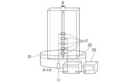
- FIG. 1 is a schematic cross-sectional view showing a cellulose fiber production apparatus according to one embodiment of the present invention.
- 1 is a photograph showing an actual configuration of the cellulose fiber production apparatus of the present embodiment.
- CNF was dispersed in water (concentration: 0.3% by mass, flow rate: 180 mL/hour), and a 1 mol/L aqueous hydrochloric acid solution was used as a coagulant in the coagulation bath.
- 1 is an explanatory diagram showing the conditions for producing cellulose fibers in the examples.
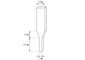
- FIG. 1 is an explanatory diagram showing the configuration of a flow path (ratio of cross-sectional area of the upstream portion to the cross-sectional area of the downstream portion: 2.0, flow path cross section 1 mm x 2 mm (rectangle)) of a cellulose fiber production device used in verification in the examples.
- FIG. 1 is an explanatory diagram showing the configuration of a flow path (ratio of cross-sectional area of the upstream portion to the cross-sectional area of the downstream portion: 3.0, flow path cross section 1 mm x 3 mm (rectangle)) of a cellulose fiber production device used in verification in the examples.
- 1 is a SEM photograph of cellulose fibers (sample) obtained in Comparative Example 1.
- 1 is a SEM photograph of cellulose fibers (sample) obtained in Example 1 of the present invention.
- 1 is a SEM photograph of cellulose fibers (sample) obtained in Example 2 of the present invention.
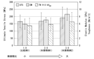
- 1 is a graph showing the tensile strength (UTS), elastic modulus (EM), and toughness (TN) of Comparative Example 1 and Invention Examples 1 and 2.
- 1 is a SEM photograph of a cellulose single fiber carrying silver nanoparticles.
- 1 is a graph showing the tensile strength (UTS), elastic modulus (EM), and toughness (TN) of Comparative Examples 11-15 prepared without the application of an electric field.
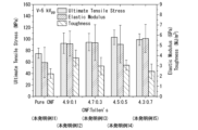
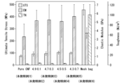
- 1 is a graph showing the tensile strength (UTS), elastic modulus (EM), and toughness (TN) of inventive examples 11-15 prepared with an applied electric field (5 kV pp ).
- 1 is a photograph evaluating the antibacterial effect of the cellulose single fiber of Comparative Example 14.
- 1 is a photograph showing the evaluation of the antibacterial effect of the cellulose single fiber of Example 14 of the present invention.
- 1 is a graph showing the tensile strength (UTS), elastic modulus (EM), and toughness (TN) of Examples 11 to 15 of the present invention and Comparative Example 16 (chemical fibers derived from commercially available products).
- FIG. 1 is a schematic cross-sectional view showing an apparatus for producing cellulose fibers according to one embodiment of the present invention.
- the cellulose fiber production apparatus 10 of this embodiment includes a flow path 11 extending along a vertical longitudinal direction L.
- the flow path 11 constitutes a tube through which a raw material liquid containing cellulose nanofibers flows from the upstream side (upper side or one side) to the downstream side (lower side or the other side) in the longitudinal direction L.
- the cross section of this flow path 11 perpendicular to the longitudinal direction L has a rectangular shape.
- the cross section perpendicular to the longitudinal direction L of the flow channel 11 is made rectangular, for example, when the raw material liquid with the aligned orientation of the cellulose nanofibers is flowed out from the bottom end of the flow channel 11 into a liquid tank containing a coagulation liquid (coagulation tank 21) (coagulation process), strong surface tension acts on the corners of the rectangle, making it possible to obtain cellulose fibers with a cross section that is closer to a perfect circle.
- coagulation tank 21 coagulation liquid
- a solution containing the coagulation liquid may be injected from the side of the flow channel.
- the flow path 11 is formed by forming a long hole that becomes the flow path 11 in a dielectric material, for example, an acrylic resin material.
- a dielectric material for example, an acrylic resin material.
- cross-sectional shape perpendicular to the longitudinal direction L of the flow path 11 is made rectangular, it can be formed by stacking plate-shaped members as described below (see Figure 2), which makes it easier to manufacture the cellulose fiber manufacturing device 10 compared to when the cross-sectional shape of the flow path is circular or the like.
- the shape of the cross section perpendicular to the longitudinal direction L of the flow path 11 can also be a rectangle with rounded corners.
- the shape of the cross section perpendicular to the longitudinal direction L of the flow path is not limited to a rectangle as in this embodiment, and can be, for example, a perfect circle, an ellipse, a hexagon, a polygon, etc. Any cross-sectional shape is acceptable as long as the raw material liquid flowing from the upstream side to the downstream side does not generate significant turbulence inside the flow path.
- the flow path 11 is composed of an upstream section 12 (first region), a downstream section 13 (second region), and a throttle section 14 (third region) connecting the upstream section 12 and the downstream section 13.
- a coagulating liquid injection pipe 15 is connected to the downstream section 13. Note that the coagulating liquid injection pipe 15 may not be connected to the flow path of the downstream section 13, and a coagulating liquid tank storing the coagulating liquid may be provided at the end of the downstream section 13. Furthermore, a supply pipe 16 for supplying the raw material liquid into the flow channel 11 may be connected to the upper end of the upstream portion 12 .
- the upstream portion 12 has a rectangular cross section perpendicular to the longitudinal direction L and extends along the longitudinal direction L with a constant cross-sectional area.
- the downstream portion 13 has a rectangular cross section perpendicular to the longitudinal direction L and extends along the longitudinal direction L with a cross-sectional area smaller than that of the upstream portion 12 .
- the rectangular cross-sectional shape of the downstream section 13 is obtained by shortening the length of one pair of opposing sides of the rectangular cross-sectional shape of the upstream section 12 and making the other pair of sides the same length. This makes the cross-sectional area of the downstream section 13 smaller than the cross-sectional area of the upstream section 12.
- the rectangular cross-sectional shape of the downstream section may be shaped so that both pairs of opposing sides that make up the rectangular cross section of the upstream section are both shorter in length.
- the constriction section 14 has a rectangular funnel shape in which the cross-sectional area perpendicular to the longitudinal direction L gradually decreases from the upstream side connected to the upstream section 12 toward the downstream side connected to the downstream section 13. This constriction section 14 gradually narrows the cross-sectional area of the upstream section 12 until it becomes the smaller cross-sectional area of the downstream section 13.
- the constriction section 14 narrows the cross-sectional area of the flow path 11 so that the ratio (S1/S2) of the cross-sectional area S1 of the upstream section 12 to the cross-sectional area S2 of the downstream section 13 is 1.5 or more. More preferably, the cross-sectional area ratio of the downstream section 13 to the upstream section 12 is 3.0 or more.
- the cross-sectional area ratio of the downstream section 13 to the upstream section 12 is less than 1.5, there is a concern that the effect of controlling the orientation of the cellulose nanofibers due to the formation of an elongational flow field, which will be described later, will be reduced.
- the cross-sectional area ratio of the downstream section 13 to the upstream section 12 is greater than 5.0, there is a concern that turbulence will occur due to a significant change in flow speed caused by a sudden decrease in cross-sectional area.
- the constriction section 14 has two opposing surfaces that form the inner surface of the constriction section 14, which are inclined surfaces 14a, so that the length of one pair of opposing sides of the flow path 11, which has a rectangular cross section, is shortened and the length of the other pair of sides is the same.
- the inclination angle ⁇ of such an inclined surface 14a with respect to the central axis Cp along the longitudinal direction L of the flow path 11 is preferably in the range of 5° or more and 30° or less. If the inclination angle ⁇ exceeds 30° and approaches a right angle, vortexes are more likely to occur near the constriction section 14, and there is a concern that the orientation of the cellulose nanofibers may be disturbed. Furthermore, if the inclination angle ⁇ is less than 5°, there is a concern that the effect of controlling the orientation of the cellulose nanofibers may be reduced.
- the flow path 11 is provided with a number of electrodes 17 for forming an electric field within the flow path through which the raw material liquid flows.
- Such electrodes 17 need only be formed at least in the upstream section 12, and preferably also in the downstream section 13. In this embodiment, the electrodes 17 are formed in both the upstream section 12 and the downstream section 13. It is also possible to form the electrodes 17 in the constriction section 14. These electrodes 17 provide the effect of controlling the orientation of the cellulose nanofibers by forming an electric field, as described below.
- the electrode 17 is made of a metal foil, for example, a copper tape, and is formed on the outer surface of the material forming the flow path 11.
- a dielectric material for example, an acrylic resin material
- a dielectric layer as the material forming the flow path 11 is disposed between the electrode 17 and the inner surface of the flow path 11 that comes into contact with the raw material liquid.
- electrodes for generating an electric field may be provided on the inner surface of the flow channel 11, and the exposed electrodes may be covered with a dielectric layer such as a resin film.
- an AC power supply (not shown) is connected to the electrode 17, and an AC electric field is formed in the flow path 11.
- a DC power supply may be connected to the electrode 17, and a DC electric field may be formed in the flow path 11.
- FIG. 2 is a photograph showing an actual configuration of the cellulose fiber production apparatus of this embodiment.
- a cellulose fiber manufacturing device 10 is composed of five plate-shaped members A to E made of acrylic resin stacked together. Of these, member C, which is located in the middle, is formed with a long groove that becomes the flow path 11. The width of this long groove is made different between the upper and lower parts, and a portion where the groove width is narrowed is formed between them, thereby forming an upstream section 12, a downstream section 13, and a constriction section 14 that configure the flow path 11.
- copper tape constituting electrode 17 is attached in a ladder shape to members B and D, which sandwich member C from both sides.
- members B and D themselves function as dielectric layers disposed between the copper tape (electrode 17) and the long groove (flow path 11) of member A.
- the cellulose fiber manufacturing device 10 of this embodiment can be formed.
- the above embodiment has been described assuming that the manufacturing apparatus 10 is used in an upright state, but there is no particular limitation on how the manufacturing apparatus 10 is placed when in use.
- the manufacturing apparatus 10 may be used in a state in which it is placed in a direction parallel to a horizontal placement surface.
- the manufacturing apparatus 10 may be used in a state in which it is placed in a state inclined with respect to the horizontal placement surface.
- the raw material liquid may be any liquid that contains cellulose nanofibers.
- TEMPO 2,2,6,6-tetramethylpiperidine 1-oxyl
- Such TEMPO-oxidized cellulose fibers using natural cellulose maintain their original fiber shape, and can be easily washed and purified by filtration, and can be stored or transported at a high solids content after squeezing.
- a transparent, highly viscous gel-like liquid raw material solution in which cellulose nanofibers are dispersed can be obtained.
- the cellulose nanofibers contained in such a raw material liquid are in a state where the longitudinal direction is randomly oriented.
- the raw material liquid Q is introduced into the flow path 11 from a supply pipe 16 connected to the upstream portion 12 of the flow path 11 of the cellulose fiber manufacturing apparatus 10.
- the raw material liquid Q flows down inside the flow path 11 from the upstream side to the downstream side of the flow path 11.
- the raw material liquid Q may flow naturally under its own weight, or may flow under pressure using a pump or the like.
- the flow rate of the raw material liquid Q flowing through the flow path 11 may be in the range of 10 to 500 mL/hour or less, or in the range of 50 to 400 mL/hour or less, or in the range of 100 to 300 mL/hour or less.
- the longitudinal direction of the cellulose nanofibers which were disordered when introduced, begins to align in the direction along the longitudinal direction L of the flow path 11 due to the action of an alternating electric field formed inside the flow path 11, and the cellulose nanofibers become oriented (first orientation process).
- the alternating current for forming such an electric field may be applied to the electrode 17 formed in the upstream portion 12 and the electrode 17 formed in the downstream portion 13 in such a manner that the power value (current, voltage) is different.
- the raw material liquid Q that flows from the upstream section 12 into the constricted section 14 is aligned so that the longitudinal direction of each cellulose nanofiber approaches the longitudinal direction L of the flow channel 11 even more due to the action of the elongational flow field formed by the flow channel constriction, in which the cross-sectional area of the flow channel 11 gradually decreases downstream (second orientation process).
- the elongational flow field is a flow field in which the fluid is stretched into elongated shapes by the elongational flow, and in such an elongational flow field, particles with elongated shapes are oriented in the direction of the fluid flow due to the elongational flow effect and shear flow effect.
- the raw material liquid Q flows from the constriction section 14 into the downstream section with a smaller cross-sectional area, and the orientation direction of the cellulose nanofibers is further aligned along the longitudinal direction L of the flow path 11 by the action of the AC electric field formed by the electrodes 17 formed in the downstream section 13, and near the lower end of the downstream section 13, most of the cellulose nanofibers are oriented along the longitudinal direction L of the flow path 11.
- the voltage applied to the electrode 17 may be in the range of 0.5 to 10.0 kVpp , 1.0 to 8.0 kVpp , or 2.0 to 6.0 kVpp .
- the raw material liquid Q containing cellulose nanofibers oriented along the longitudinal direction L is then solidified into cellulose fibers F with a fiber diameter approximately equal to the width of the downstream section 13 by, for example, a coagulation liquid S injected into the flow path 11 via a coagulation liquid injection tube 15 connected to the downstream section 13 (coagulation process).
- a coagulation liquid S injected into the flow path 11 via a coagulation liquid injection tube 15 connected to the downstream section 13 (coagulation process).
- dilute hydrochloric acid or a solution containing polyvalent metal ions can be used as the coagulation liquid S to promote hydrogen bonding and aggregate into a fibrous form.
- the coagulation liquid injection pipe 15 may not be connected to the flow path of the downstream section 13, and a coagulation liquid tank storing coagulation liquid may be provided at the end of the downstream section 13.
- the raw material liquid Q in which the orientation direction of the cellulose nanofibers is aligned with the longitudinal direction L of the flow path 11 and flows out from the end of the downstream section 13, immediately comes into contact with the coagulation liquid after flowing out and coagulates into cellulose fibers F with a fiber diameter approximately equal to the width of the flow path of the downstream section 13 (coagulation process).
- the first orientation step, the second orientation step and the solidification step may be carried out at room temperature (eg, 18 to 25° C.).
- the first orientation step, the second orientation step, and the solidification step may be performed at a constant temperature, or may be performed at different temperatures depending on the step.
- the solidification step may be carried out at a temperature in the range of 10 to 50°C.
- the cellulose fiber F thus obtained has an orientation rate, which is the proportion of cellulose nanofibers oriented along the longitudinal direction among all the cellulose nanofibers contained therein, of 90% or more.
- the cellulose fiber F obtained by the cellulose fiber manufacturing method of this embodiment has high tensile strength and excellent toughness compared to cellulose fibers having a low orientation rate of cellulose nanofibers. In addition, it has a high elastic modulus and is easy to process, and woven fabrics using such cellulose fibers can be easily formed.
- a solution containing cellulose nanofibers is used as the raw material liquid, but it is also preferable to use a raw material liquid that contains carbon nanotubes and metal nanoparticles in addition to cellulose nanofibers.
- cellulose fibers are formed using a raw material liquid that contains carbon nanotubes in addition to cellulose nanofibers
- conductive cellulose fibers are obtained in which carbon nanotubes are wrapped around the cellulose nanofibers.
- the problem with conductive cellulose fibers has been that there is a trade-off between electrical conductivity and tensile strength.
- the cellulose fiber manufacturing method of this embodiment it is possible to control the orientation of the raw material liquid containing cellulose nanofibers and carbon nanotubes, and to realize carbon nanotube-containing cellulose fibers with high electrical conductivity and high tensile strength.
- cellulose fibers are formed using a raw material solution that contains, in addition to cellulose nanofibers, metal nanoparticles, for example silver nanoparticles
- metal nanoparticles for example silver nanoparticles
- silver nanoparticles By supporting silver nanoparticles on cellulose fibers in this manner, it is also possible to impart antibacterial properties to the cellulose fibers.
- the average particle size of the nanoparticles (including carbon nanotubes) supported on the cellulose fibers may be 1 to 1000 nm, 10 to 1000 nm, or 100 to 500 nm.
- the average diameter of the cellulose fibers may be 10 to 500 ⁇ m, 20 to 400 ⁇ m, or 50 to 200 ⁇ m.
- the average length of the cellulose fibers may be 1 to 10 m, 1 to 100 cm ⁇ m, or 1 to 10 cm.
- the silver content in the cellulose fibers carrying silver nanoparticles may be in the range of 1.0 to 10.0% by mass, 2.0 to 9.0% by mass, or 3.0 to 8.0% by mass.
- the elastic modulus of the cellulose fibers may be in the range of 3 to 40 GPa, or in the range of 4 to 8 GPa, or in the range of 4 to 7 GPa.
- FIG. 3 shows the configuration of the cellulose fiber manufacturing apparatus used in the verification and the manufacturing conditions. 4, a flow path was formed in which the cross-sectional area ratio of the upstream portion to the downstream portion was 1.0, i.e., no throttle portion was formed, as Comparative Example 1. Also, a flow path was formed in which the cross-sectional area ratio of the upstream portion to the downstream portion was 1.5, as Inventive Example 1. Furthermore, as Inventive Example 2, a flow path was formed in which the cross-sectional area ratio of the upstream portion to the downstream portion was 3.0.
- FIG. 5 shows SEM photographs of the cellulose fibers (samples) obtained in Comparative Example 1 and Invention Examples 1 and 2.
- the tensile strength (UTS), elastic modulus (EM), and tenacity (TN) of the cellulose fibers of each sample were then measured, and the results are shown graphically in FIG. 6, the cellulose fiber of Inventive Example 1 had a tensile strength (UTS) that was about 15% higher than that of Comparative Example 1, and the cellulose fiber of Inventive Example 2 had a tensile strength (UTS) that was about 42% higher than that of Comparative Example 1. Furthermore, the cellulose fiber of Inventive Example 2 had a modulus of elasticity (EM) that was about 28% higher than that of Comparative Example 1. Furthermore, the cellulose fiber of Inventive Example 2 had a toughness (TN) that was about 15% higher than that of Comparative Example 1.
- the cellulose fiber manufacturing method using the cellulose fiber manufacturing apparatus of this embodiment can produce cellulose fibers with excellent tensile strength, elastic modulus, and toughness by controlling the orientation using an electric field and the elongational flow field formed by the squeezing section.
- Example 2 Cellulose fibers carrying silver nanoparticles were prepared using the method described below, and their antibacterial properties were evaluated.
- Tollens reagent (Ag(NH 3 ) 2 OH) was used to prepare silver nanoparticles.
- raw material solution S14 a sample mixed in No. 5
- raw material solution S15 a sample mixed with CNF and Tollens reagent in a mixing ratio of 4.3:0.7
- the raw material liquids S11 to S15 were used as the raw material liquids to produce cellulose fibers in the same manner as in Example 1 unless otherwise specified.
- the cellulose fiber was produced under the following conditions in Example 2.
- Coagulant 1 mol/L HCl aqueous solution
- the cellulose fibers produced from the raw material solutions S11 to S15 without applying voltage to the electrodes were designated as Comparative Examples 11 to 15, respectively.
- the cellulose fibers produced from the raw material solutions S11 to S15 with the voltage applied to the electrodes were named Invention Examples 11 to 15, respectively.
- Example 2 An SEM photograph of the cellulose fibers of Example 2 is shown in FIG.
- the surface properties of the short cellulose fibers in Examples 1 and 2 were streaky and uneven, and the CNFs were bundled and oriented in the axial direction. Furthermore, silver nanoparticles of 200 to 700 nm were found to be distributed almost uniformly inside the fiber.
- the tensile strength (UTS), elastic modulus (EM), and toughness (TN) of the cellulose fibers were measured for Comparative Examples 11 to 15, which were performed without applying voltage to the electrode 17, and for Inventive Examples 11 to 15, which were performed with applying voltage to the electrode 17.
- the results are shown in the graphs of Figures 8 and 9, respectively. According to the results shown in Figures 8 and 9, compared to the cellulose fibers of Comparative Examples 11 to 15, the cellulose fibers of Examples 11 to 15 of the present invention had significantly higher or at least equivalent tensile strength (UTS), elastic modulus (EM), and toughness (TN).
- Example 15 of the present invention the difference between Comparative Example 15 and the presence or absence of application of voltage to electrode 17 was the largest.
- the presence of excess silver nanoparticles impaired the affinity between CNFs, and it is believed that sufficiently oriented cellulose fibers could not be produced without an electric field.
- the tensile strength (UTS), elastic modulus (EM) and toughness (TN) were significantly increased.
- Figures 10 and 11 are photographs evaluating the antibacterial effects of cellulose single fibers of Comparative Example 14 and Invention Example 14.
- natto bacteria a type of gram-positive bacterium, Bacillus subtilis
- the cellulose single fibers of Comparative Example 14 and Inventive Example 14 were each inoculated into a test bacteria solution (tryptic soy agar ICR 30 mL) and cultured with shaking in an incubator at 37° C. for 24 hours. Thereafter, the culture solution was diluted and poured onto an agar medium, and cultured in an incubator at 37° C. for 24 hours.
- FIG. 12 is a graph showing the tensile strength (UTS), elastic modulus (EM), and toughness (TN) of invention examples 11 to 15 and comparative example 16 (chemical fiber derived from a commercially available product).
- the data for Inventive Examples 11 to 15 in FIG. 12 is the same as that shown in FIG. 9, but the scale of the vertical axis has been changed for comparison with Comparative Example 16, so the profiles of the bar graphs look significantly different.
- the chemical fiber of Comparative Example 16 was prepared from commercially available drainage stockings (materials: polyester, polyurethane, heat resistance: 100°C, cold resistance: -30°C).
- the obtained chemical fibers had an average diameter of 45.7 ⁇ m, an average tensile strength (UTS) of 457.7 MPa, an average elastic modulus (EM) of 3.7 GPa, an average failure strain of 0.31, and an average toughness (TN) of 100.8 MJ/ m3 .
- the cellulose fibers of the present invention Nos. 11 to 15 exhibited lower values (1/5 to 1/50) of the tensile strength (UTS) and toughness (TN) than the chemical fiber of Comparative Example No. 16.
- the elastic modulus the cellulose fibers of the present inventions 11 to 15 exhibited values equivalent to or higher than that of the chemical fiber of Comparative Example 16.
- the cellulose fibers of Examples 12 to 15 carrying silver nanoparticles exhibited elastic modulus that was 40% or more higher than that of Comparative Example 16.
- the cellulose fiber manufacturing apparatus and cellulose fiber manufacturing method of the present invention are simply configured to produce cellulose fibers with unidirectional orientation of cellulose nanofibers and improved tensile strength, elastic modulus, and toughness. Therefore, they have industrial applicability.
Landscapes
- Engineering & Computer Science (AREA)
- Chemical & Material Sciences (AREA)
- Textile Engineering (AREA)
- Chemical Kinetics & Catalysis (AREA)
- General Chemical & Material Sciences (AREA)
- Mechanical Engineering (AREA)
- Manufacturing & Machinery (AREA)
- Life Sciences & Earth Sciences (AREA)
- Biochemistry (AREA)
- Materials Engineering (AREA)
- Health & Medical Sciences (AREA)
- Medicinal Chemistry (AREA)
- Polymers & Plastics (AREA)
- Organic Chemistry (AREA)
- Artificial Filaments (AREA)
Priority Applications (1)
| Application Number | Priority Date | Filing Date | Title |
|---|---|---|---|
| JP2025543436A JPWO2025047621A1 (https=) | 2023-08-25 | 2024-08-23 |
Applications Claiming Priority (2)
| Application Number | Priority Date | Filing Date | Title |
|---|---|---|---|
| JP2023137034 | 2023-08-25 | ||
| JP2023-137034 | 2023-08-25 |
Publications (1)
| Publication Number | Publication Date |
|---|---|
| WO2025047621A1 true WO2025047621A1 (ja) | 2025-03-06 |
Family
ID=94818974
Family Applications (1)
| Application Number | Title | Priority Date | Filing Date |
|---|---|---|---|
| PCT/JP2024/030056 Pending WO2025047621A1 (ja) | 2023-08-25 | 2024-08-23 | セルロース繊維の製造装置、セルロース繊維の製造方法及びセルロース繊維 |
Country Status (2)
| Country | Link |
|---|---|
| JP (1) | JPWO2025047621A1 (https=) |
| WO (1) | WO2025047621A1 (https=) |
Citations (8)
| Publication number | Priority date | Publication date | Assignee | Title |
|---|---|---|---|---|
| JP2007532790A (ja) * | 2004-04-08 | 2007-11-15 | リサーチ・トライアングル・インスティチュート | 回転可能なスプレーヘッドを用いたファイバーのエレクトロスピニング |
| US20120040581A1 (en) * | 2009-04-01 | 2012-02-16 | Centro De Estudios Investigaciones Tecnicas De Gipuzkoa | Template-supported method of forming patterns of nanofibers in the electrospinning process and uses of said nanofibers |
| JP2012092478A (ja) * | 2010-09-29 | 2012-05-17 | Panasonic Corp | 不織布製造装置、および、不織布製造方法 |
| JP2018503008A (ja) * | 2014-12-23 | 2018-02-01 | スピンノヴァ オイSpinnova Oy | 高引張強度ナノファイバ糸の製造方法 |
| JP2021080601A (ja) * | 2019-11-19 | 2021-05-27 | 防衛装備庁長官 | 紡績方法、紡績装置及び繊維束 |
| JP2022184334A (ja) * | 2021-06-01 | 2022-12-13 | 株式会社スギノマシン | 複合体、抗菌剤、及び複合体の製造方法 |
| JP2023019599A (ja) * | 2021-07-29 | 2023-02-09 | 国立大学法人福井大学 | 複合繊維、その製造方法、および繊維製品 |
| JP2023029631A (ja) * | 2019-04-25 | 2023-03-03 | 東洋製罐グループホールディングス株式会社 | セルロースナノクリスタル複合体及びその製造方法 |
-
2024
- 2024-08-23 JP JP2025543436A patent/JPWO2025047621A1/ja active Pending
- 2024-08-23 WO PCT/JP2024/030056 patent/WO2025047621A1/ja active Pending
Patent Citations (8)
| Publication number | Priority date | Publication date | Assignee | Title |
|---|---|---|---|---|
| JP2007532790A (ja) * | 2004-04-08 | 2007-11-15 | リサーチ・トライアングル・インスティチュート | 回転可能なスプレーヘッドを用いたファイバーのエレクトロスピニング |
| US20120040581A1 (en) * | 2009-04-01 | 2012-02-16 | Centro De Estudios Investigaciones Tecnicas De Gipuzkoa | Template-supported method of forming patterns of nanofibers in the electrospinning process and uses of said nanofibers |
| JP2012092478A (ja) * | 2010-09-29 | 2012-05-17 | Panasonic Corp | 不織布製造装置、および、不織布製造方法 |
| JP2018503008A (ja) * | 2014-12-23 | 2018-02-01 | スピンノヴァ オイSpinnova Oy | 高引張強度ナノファイバ糸の製造方法 |
| JP2023029631A (ja) * | 2019-04-25 | 2023-03-03 | 東洋製罐グループホールディングス株式会社 | セルロースナノクリスタル複合体及びその製造方法 |
| JP2021080601A (ja) * | 2019-11-19 | 2021-05-27 | 防衛装備庁長官 | 紡績方法、紡績装置及び繊維束 |
| JP2022184334A (ja) * | 2021-06-01 | 2022-12-13 | 株式会社スギノマシン | 複合体、抗菌剤、及び複合体の製造方法 |
| JP2023019599A (ja) * | 2021-07-29 | 2023-02-09 | 国立大学法人福井大学 | 複合繊維、その製造方法、および繊維製品 |
Non-Patent Citations (1)
| Title |
|---|
| KARL M. O. HåKANSSON, FALL ANDREAS B., LUNDELL FREDRIK, YU SHUN, KRYWKA CHRISTINA, ROTH STEPHAN V., SANTORO GONZALO, KVICK MA: "Hydrodynamic alignment and assembly of nanofibrils resulting in strong cellulose filaments", NATURE COMMUNICATIONS, NATURE PUBLISHING GROUP, UK, vol. 5, UK, XP055474967, ISSN: 2041-1723, DOI: 10.1038/ncomms5018 * |
Also Published As
| Publication number | Publication date |
|---|---|
| JPWO2025047621A1 (https=) | 2025-03-06 |
Similar Documents
| Publication | Publication Date | Title |
|---|---|---|
| JP4875820B2 (ja) | コロイド粒子、特にカーボンナノチューブからの巨視的繊維およびリボンの製造方法 | |
| Huang et al. | Simultaneous reinforcement and toughening of carbon nanotube/cellulose conductive nanocomposite films by interfacial hydrogen bonding | |
| CN1433443B (zh) | 嵌入聚合物基质中的取向纳米纤维 | |
| Chronakis | Novel nanocomposites and nanoceramics based on polymer nanofibers using electrospinning process—A review | |
| Wang et al. | Mechanical and electrical properties of electrospun PVDF/MWCNT ultrafine fibers using rotating collector | |
| CN1296436C (zh) | 一种基于碳纳米管的复合材料的制备方法 | |
| Jiang et al. | Short nylon-6 nanofiber reinforced transparent and high modulus thermoplastic polymeric composites | |
| Li et al. | Highly elastic fibers made from hydrogen-bonded polymer complex | |
| KR20110050454A (ko) | 감소된 저항을 가지는 탄소 나노튜브 포함 복합 물질의 제조 방법 | |
| Ghobadi et al. | Graphene-reinforced poly (vinyl alcohol) electrospun fibers as building blocks for high performance nanocomposites | |
| JP2010539342A (ja) | コロイド粒子を含む複合繊維の連続製造方法 | |
| KR20130040783A (ko) | 셀룰로스계 섬유의 제조 방법 및 상기 방법에 의해 제조된 섬유 | |
| Qiu et al. | Super strong all-cellulose composite filaments by combination of inducing nanofiber formation and adding nanofibrillated cellulose | |
| Nakashima et al. | Mechanical properties of poly (vinylidene fluoride) nanofiber filaments prepared by electrospinning and twisting | |
| CN107698754B (zh) | 一种氧化石墨烯改性聚酰胺-6的制备方法 | |
| Habeeb et al. | Improving the physical properties of nanofibers prepared by electrospinning from polyvinyl chloride and polyacrylonitrile at low concentrations | |
| Zha et al. | Improved mechanical and electrical properties in electrospun polyimide/multiwalled carbon nanotubes nanofibrous composites | |
| WO2025047621A1 (ja) | セルロース繊維の製造装置、セルロース繊維の製造方法及びセルロース繊維 | |
| CN115233320B (zh) | 高导电异形复合纤维的制备方法 | |
| Li et al. | Fabrication and characterization of recyclable carbon nanotube/polyvinyl butyral composite fiber | |
| KR100851431B1 (ko) | 전기방사법에 의한 고분자 섬유 내 탄소나노튜브의배향방법 | |
| Karahan Toprakci et al. | Nailed-bat like halloysite nanotube filled polyamide 6, 6 nanofibers by electrospinning | |
| CN112708949B (zh) | 一种基于微流体组装高强度纳米纤维素纤维的制备方法 | |
| KR101308183B1 (ko) | 전도성 고분자 복합체 및 이의 성형방법 | |
| CN105177766B (zh) | 一种中间相沥青连续长丝的制备方法 |
Legal Events
| Date | Code | Title | Description |
|---|---|---|---|
| 121 | Ep: the epo has been informed by wipo that ep was designated in this application |
Ref document number: 24859654 Country of ref document: EP Kind code of ref document: A1 |
|
| ENP | Entry into the national phase |
Ref document number: 2025543436 Country of ref document: JP Kind code of ref document: A |
|
| WWE | Wipo information: entry into national phase |
Ref document number: 2025543436 Country of ref document: JP |