WO2025041297A1 - 工作機械 - Google Patents
工作機械 Download PDFInfo
- Publication number
- WO2025041297A1 WO2025041297A1 PCT/JP2023/030300 JP2023030300W WO2025041297A1 WO 2025041297 A1 WO2025041297 A1 WO 2025041297A1 JP 2023030300 W JP2023030300 W JP 2023030300W WO 2025041297 A1 WO2025041297 A1 WO 2025041297A1
- Authority
- WO
- WIPO (PCT)
- Prior art keywords
- tool
- workpiece
- mounting state
- control device
- imaging
- Prior art date
- Legal status (The legal status is an assumption and is not a legal conclusion. Google has not performed a legal analysis and makes no representation as to the accuracy of the status listed.)
- Pending
Links
Images

Classifications
-
- B—PERFORMING OPERATIONS; TRANSPORTING
- B23—MACHINE TOOLS; METAL-WORKING NOT OTHERWISE PROVIDED FOR
- B23Q—DETAILS, COMPONENTS, OR ACCESSORIES FOR MACHINE TOOLS, e.g. ARRANGEMENTS FOR COPYING OR CONTROLLING; MACHINE TOOLS IN GENERAL CHARACTERISED BY THE CONSTRUCTION OF PARTICULAR DETAILS OR COMPONENTS; COMBINATIONS OR ASSOCIATIONS OF METAL-WORKING MACHINES, NOT DIRECTED TO A PARTICULAR RESULT
- B23Q15/00—Automatic control or regulation of feed movement, cutting velocity or position of tool or work
-
- G—PHYSICS
- G05—CONTROLLING; REGULATING
- G05B—CONTROL OR REGULATING SYSTEMS IN GENERAL; FUNCTIONAL ELEMENTS OF SUCH SYSTEMS; MONITORING OR TESTING ARRANGEMENTS FOR SUCH SYSTEMS OR ELEMENTS
- G05B19/00—Program-control systems
- G05B19/02—Program-control systems electric
- G05B19/18—Numerical control [NC], i.e. automatically operating machines, in particular machine tools, e.g. in a manufacturing environment, so as to execute positioning, movement or co-ordinated operations by means of program data in numerical form
- G05B19/4093—Numerical control [NC], i.e. automatically operating machines, in particular machine tools, e.g. in a manufacturing environment, so as to execute positioning, movement or co-ordinated operations by means of program data in numerical form characterised by part programming, e.g. entry of geometrical information as taken from a technical drawing, combining this with machining and material information to obtain control information, named part program, for the NC machine
-
- B—PERFORMING OPERATIONS; TRANSPORTING
- B23—MACHINE TOOLS; METAL-WORKING NOT OTHERWISE PROVIDED FOR
- B23Q—DETAILS, COMPONENTS, OR ACCESSORIES FOR MACHINE TOOLS, e.g. ARRANGEMENTS FOR COPYING OR CONTROLLING; MACHINE TOOLS IN GENERAL CHARACTERISED BY THE CONSTRUCTION OF PARTICULAR DETAILS OR COMPONENTS; COMBINATIONS OR ASSOCIATIONS OF METAL-WORKING MACHINES, NOT DIRECTED TO A PARTICULAR RESULT
- B23Q17/00—Arrangements for observing, indicating or measuring on machine tools
- B23Q17/24—Arrangements for observing, indicating or measuring on machine tools using optics or electromagnetic waves
Definitions
- This disclosure relates to technology for acquiring the status of machine tools.
- Patent Document 1 describes a processing device that acquires information from a workpiece.
- the processing device in Patent Document 1 uses an imaging device to capture an image of the workpiece placed on a stage and reads the barcode on the workpiece.
- the processing device acquires information about the workpiece, such as the material of the workpiece, from the read barcode.
- the machine tool in Patent Document 1 mentioned above is configured to perform grinding by applying a grinding wheel to a workpiece placed on a stage.
- the information required differs depending on the configuration of the machine tool, and there is room for improvement in terms of acquiring the information.
- This disclosure was made in consideration of the above problems, and aims to provide a machine tool that can acquire the setting information necessary to create a machining program.
- this specification discloses a machine tool that includes a work holding device that holds a workpiece, a processing device capable of mounting a tool that performs processing on the workpiece held by the work holding device, an acquisition device that can acquire at least one of the mounting states of the workpiece in the work holding device and the mounting state of the tool in the processing device, and a processing device that sets setting information required to create a processing program that controls the processing operation based on the mounting states acquired by the acquisition device.
- the acquisition device can acquire at least one of the attachment states of the workpiece in the work holding device and the attachment state of the tool in the processing device.
- the processing device sets the setting information required to create a processing program that controls the processing operation based on the attachment state acquired by the acquisition device.
- setting information such as the size of the base material before processing and the protrusion amount of the base material can be set based on the acquired state acquired by the acquisition device.
- setting information such as the type of tool and the protrusion amount of the tool can be acquired by the acquisition device and set based on the acquired state.
- the setting information required to create the processing program can be automatically acquired and set.
- FIG. 1 is a perspective view of a machine tool according to an embodiment.
- Block diagram of a machine tool A close-up of the turret with tooling attached.
- 1A and 1B are diagrams for explaining a comparative example and an embodiment in the flow of creating a program. A diagram showing the procedure manual.
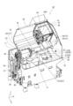
- Fig. 1 shows a perspective view of the machine tool 10 of this embodiment as seen from the front side.
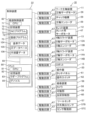
- Fig. 2 shows a block diagram of the machine tool 10 according to this embodiment. Note that Fig. 1 does not show the device cover of the machine tool 10. As shown in Fig.
- the direction along the spindle of the work spindle device 11 described later is referred to as the Z-axis direction
- the direction perpendicular to the Z-axis direction and in which the turret device 12 moves along the guide surface 19 is referred to as the X-axis direction
- the direction perpendicular to the X-axis and Z-axis directions is referred to as the Y-axis direction.
- the machine tool 10 is, for example, a turret lathe in which the rotation axis of the turret device 12 is parallel to the Z axis.
- the machine tool 10 is equipped with a work spindle device 11, a turret device 12, an X-axis slide device 13, a Z-axis slide device 14, a robot 15 (see FIG. 2), a bed 16 serving as a base, an operation panel 20 (see FIG. 2), a control device 22 (see FIG. 2), an imaging device 56, and a tool setter 57.
- the configuration of the machine tool 10 shown in FIG. 1 and FIG. 2 is an example.
- the machine tool 10 may be a lathe equipped with multiple sets of work spindle devices 11 and turret devices 12, or may be a so-called multi-tasking machine equipped with a tool spindle device in addition to a lathe. Therefore, the machine tool disclosed herein is not limited to a lathe, and machine tools of various configurations that can be equipped with tools, such as a machining center, a milling machine, and a drill press, can be used.
- the machine tool 10 may also be configured without the robot 15.
- the bed 16 is formed with a box-shaped chip collection section 17 that opens upward, and chips generated during the machining of the workpiece W are collected in the chip collection section 17.
- the bed 16 is a slant-type bed that has a guide surface 19 that is inclined toward the chip collection section 17 in front of the device.
- the work spindle device 11 is fixed to the bed 16 and includes a headstock 23 and a rotating device 24.
- the headstock 23 can be fitted with a chuck mechanism 28 that holds (grabs) the workpiece W.
- the chuck mechanism 28 includes, for example, a backing plate 31 for seating the workpiece W and a number of chuck jaws 32 for chucking the workpiece W seated on the backing plate 31 as a mechanism for holding the workpiece W.
- the chuck mechanism 28 for holding the workpiece W is not limited to a mechanism using the chuck jaws 32, and other mechanisms such as a collet chuck can be used.
- the chuck mechanism 28 includes an air cylinder or hydraulic cylinder as a drive source, and drives the drive source based on the control of the control device 22 (see FIG.
- the headstock 23 holds the workpiece W by the chuck mechanism 28 at a position above the chip collection section 17.
- the work spindle device 11 rotates the work W held by the chuck mechanism 28 around a work spindle parallel to the Z-axis direction. Note that the work spindle device 11 is not limited to a configuration in which the headstock 23 is fixed, and may be configured so that the headstock 23 slides relative to the bed 16 in the Z-axis direction, etc.
- the shank 33C is fixed to the first mounting portion 35 by the holder 37.
- the holder 37 is fixed to a predetermined first mounting portion 35 (tool mounting portion 45) by a threaded member 38.
- the shank 33C of the cutting tool 33 attached to the first attachment portion 35 is a member shaped like a generally cylindrical or rectangular column that is long in the Z-axis direction.
- the base end is inserted into the holder 37 and held by the holder 37.
- the position of the shank 33C in the Z-axis direction is fixed by a bolt screwed into the holder 37. By loosening this bolt, the shank 33C can move relative to the holder 37 in the Z-axis direction.
- a tip 33B is detachably attached to the cutting edge 33A at the tip of the shank 33C.
- the tip 33B is fixed to the cutting edge 33A by a screw member 39 such as a bolt or a screw.
- the turret device 12 has, for example, a turret servo motor 47 (see FIG. 2) built into the turret body 41.
- the rotational operation of the turret servo motor 47 is controlled by the control device 22, and the turret device 12 rotates the turret 43 around a rotation axis parallel to the Z-axis direction.
- the turret device 12 rotates the turret 43 to change the tool (such as the cutting tool 33) indexed to the work position, and performs processing on the workpiece W held by the work spindle device 11 using the tool indexed to the work position.
- the turret servo motor 47 In addition to rotating the turret 43, the turret servo motor 47 also functions as a drive source for rotating a rotating tool (such as an end mill) attached to the turret 43.
- the control device 22 controls, for example, the turret servo motor 47 to perform the rotation indexing of the turret 43 and the rotation of the rotating tool attached to the turret 43.
- the turret device 12 may be configured to have a drive source for rotating the rotating tool in addition to the drive source for rotation. Additionally, the turret 43 may be configured so that it cannot accommodate rotating tools and can only accommodate cutting tools.
- the X-axis slide device 13 and the Z-axis slide device 14 are devices that change the position of the turret device 12 (the tool at the work position).
- the Z-axis slide device 14 is a device that moves the turret device 12, for example, in the Z-axis direction (the direction approaching the workpiece W or the direction moving away from the workpiece W) that is parallel to the workpiece spindle.
- the X-axis slide device 13 is a device that moves the turret device 12 in the X-axis direction, i.e., in a direction perpendicular to the Z-axis direction.
- the imaging device 56 is a device that captures images of the turret 43, the tools, the workpiece W, the chuck mechanism 28, etc.
- the imaging device 56 includes a camera 58, a movable section 59 (see FIG. 2), and a reflection suppression section 60 (see FIG. 2).
- the camera 58 includes an imaging element such as a CCD or CMOS, captures images based on the control of the control device 22, and outputs the captured image data to the control device 22.
- the captured image data may be two-dimensional data or three-dimensional data.
- the control device 22 acquires the captured image data captured by the camera 58 as the mounting state of the tools in the turret 43 and the mounting state of the workpiece W in the workpiece spindle device 11, and sets the setting information based on the acquired imaging data (acquired state). Details of the setting information to be set will be described later.
- the camera 58 is also equipped with lighting, and the lighting can be turned on and off and the intensity of the lighting can be changed based on the control of the control device 22.
- the reflection suppression unit 60 includes, for example, a polarizing filter and a rotation mechanism for rotating the polarizing filter.
- a polarizing filter In the machining chamber of the machine tool 10, reflections due to lighting and metal covers may occur, which may cause halation.
- the user checks the imaging data captured at each imaging position and sets the rotation angle of the polarizing filter for each imaging position in advance.
- the control device 22 associates the imaging position with the rotation angle of the polarizing filter at that imaging position and stores it in the storage device 72.
- the control device 22 When performing imaging at an arbitrary imaging position, the control device 22 reads out the rotation angle of the polarizing filter that is set in advance according to that imaging position from the storage device 72, and controls the rotation mechanism of the reflection suppression unit 60 according to the read rotation angle to adjust the polarizing filter to the set rotation angle. This can improve the accuracy of detecting the target object (workpiece W, etc.) from the imaging data.
- the control device 22 may process the imaging data and automatically adjust the rotation angle of the polarizing filter based on the results of the image processing.
- the control device 22 may also automatically adjust the intensity of the lighting light, the shutter time of the camera 58, etc.
- the imaging device 56 is an example of an acquisition device of the present disclosure.
- the imaging device 56 is not limited to the configuration described above.
- the machine tool 10 may be provided with an imaging device 56 that images the workpiece W in addition to the imaging device 56 that images the tool. That is, the machine tool 10 may be provided with multiple imaging devices 56.
- mist, water droplets, cutting chips, etc. scatter within the machining chamber.
- the imaging device 56 may be provided with a wiper that removes scattered objects from the camera 58, a shutter that protects the camera 58 from scattered objects, etc.
- the acquisition device that acquires the attachment state of the tool or workpiece is not limited to the camera 58 (imaging device 56).
- the acquisition device of the present disclosure may be a sensor capable of detecting the shape of the tool or workpiece W. Specifically, it may be a 3D scanner using infrared rays or a laser, or a non-contact sensor using ultrasound or microwaves. Alternatively, the acquisition device may be a contact sensor using a limit switch, a differential transformer (coil), or the like.
- the acquisition device may be provided with a movable part 59 that changes the detection direction of the sensor, as in the case of the camera 58.
- the acquisition device may also be a combination of the camera 58 and a sensor.
- the tool setter 57 is a device that detects the cutting edge of the tool.
- the tool setter 57 is equipped with, for example, an arm 57A, a cutting edge detection sensor 57B, and a sensor drive unit 57C (see FIG. 2).
- the arm 57A extends from below the headstock 23 toward the front of the headstock 23 within the machining chamber.
- the cutting edge detection sensor 57B is a contact-type sensor that is provided at the tip of the arm 57A.
- the cutting edge detection sensor 57B outputs a detection signal to the control device 22 in response to contact with the cutting edge of the tool (such as the cutting edge of the tip 33B).
- the sensor drive unit 57C is, for example, a rotation mechanism that rotates the arm 57A around the base end.
- the sensor driver 57C rotates the arm 57A to switch the position of the cutting edge detection sensor 57B between a detection position where it contacts the cutting edge of the tool and a retracted position where it is retracted from the tool and workpiece W.
- the control device 22 also includes a numerical control device 65 and a PLC 66.
- the numerical control device 65 includes a CPU 71 and a storage device 72.
- the PLC 66 includes a CPU 81 and a storage device 82.
- the storage devices 72, 82 include, for example, RAM, ROM, flash memory, and HDD. Note that the configuration of the storage devices 72, 82 is not limited to the above configuration, and may include an SSD instead of an HDD, an external storage device such as a USB memory, a storage medium such as a DVD-RAM, or a combination of these.
- the machine tool 10 also includes a plurality of drive circuits 67 that connect the control device 22 to each of the above-mentioned devices (workpiece spindle device 11, turret device 12, X-axis slide device 13, Z-axis slide device 14, robot 15, operation panel 20, imaging device 56, and tool setter 57).
- the control device 22 is electrically connected to each device via the drive circuits 67, and is capable of controlling each device.
- the drive circuit 67 is a driver circuit (servo amplifier) that changes the power (such as three-phase AC current) supplied to each motor (such as a servo motor) based on the instruction signal (such as the amount of movement, the position of the movement destination, the movement speed, and the target torque) of the control device 22.
- the drive circuit 67 is connected to the operation panel 20, for example, the drive circuit 67 is an amplifier circuit that amplifies the signal input from the operation panel 20.
- the storage device 72 also stores a number of NC programs 73 for numerically controlling the operations of the work spindle device 11, the turret device 12, the X-axis slide device 13, the Z-axis slide device 14, the robot 15, and the like.
- the numerical control device 65 executes the NC program 73 in the CPU 71, and controls by outputting instruction signals to the drive circuit 67 (driver circuit) according to the numerical commands described in the NC program 73.
- the drive circuit 67 executes feedback control to change the current of the three-phase AC based on, for example, encoder information from an encoder (such as the X-axis encoder 13B) attached to each servo motor (such as the X-axis servo motor 13A) and an instruction signal from the control device 22, and notifies the numerical control device 65 of the completion of processing, etc., as appropriate.
- the control device 22 slides the turret 43 (tool), the head of the robot 15, and the like along each axis direction to the desired position based on the numerical control by the numerical control device 65.
- the drive source for sliding each device is not limited to a servo motor, and other drive sources such as a stepping motor and a linear motor can also be used.
- control device 22 stores the reference data 104, the claw database 105, and the procedure manual data 106, which will be described later, in the storage device 72.
- the control device 22 may store the reference data 104, the claw database 105, and the procedure manual data 106 in a storage device other than the storage device 72.
- the control device 22 may store the reference data 104, etc. in the storage device 82 of the PLC 66, an external storage device connected to the machine tool 10, etc.
- PLC 66 is a programmable logic controller.
- a ladder program 83 for constructing a ladder circuit for processing various signals is stored in storage device 82.
- PLC 66 executes ladder program 83 in CPU 81, and executes sequence processing based on ladder program 83 to perform, for example, a process of outputting an output signal to various elements such as lamps provided in machine tool 10 to drive them, and a process of inputting an input signal from elements such as limit switches.
- PLC 66 is also connected to numerical control device 65 via, for example, communication bus 69, and is capable of communicating with numerical control device 65.
- PLC 66 executes input and output of signals between numerical control device 65 and PLC 66 using devices 85 constructed based on ladder program 83.
- Device 85 is, for example, a storage area constructed on storage device 82 by executing ladder program 83 on CPU 81, and is a device that stores signal values of external I/O (sensors, etc.) equipped on machine tool 10, a device that stores signal values for communication with numerical control device 65, a device that realizes a keep relay that stores setting values, etc.
- PLC 66 relays signals (input/output) between external I/O equipped on machine tool 10 and numerical control device 65.
- the storage device 72 also stores a registration program 75 and various other data required for machining (not shown).
- the registration program 75 sets setting information based on the acquisition state acquired by the imaging device 56 and the tool setter 57.
- the control device 22 may simply state the device name to execute the registration program 75 with the CPU 71 to control each device. For example, "the control device 22 executes imaging with the imaging device 56" means “the control device 22 executes the registration program 75 with the CPU 71 and controls the imaging device 56 via the drive circuit 67 to execute imaging with the camera 58.”
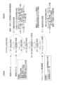
- Fig. 4 shows a flow for creating the NC program 73.
- the program can be created by following the flow of steps (hereinafter simply referred to as S) 1 to S7 shown in Fig. 4.
- Fig. 4 also illustrates a comparison between a comparative example (left side of Fig. 4) in which setting information is manually input, and this embodiment (right side of Fig. 4).
- the user operates the touch panel 61 of the machine tool 10 to register setting information for the base material before machining in S1.
- the user registers information on the tools to be used in S2.
- the user selects tools to be attached to each tool mounting portion 45 (holder number) of the turret 43 from the registered tools in S3, and associates the tools with the holder numbers.
- the holder number here is a number that identifies multiple tool mounting portions 45.
- the user sets the order of the machining processes in S4.
- the user sets the machining conditions for each process set in S5 in S4.
- the machining conditions are, for example, the number of rotations (rotation speed) per unit time of the workpiece W, the tool to be used, the feed amount, etc.
- the user sets dimensional values (cutting diameter, etc.) in S6. This allows the setting information for creating the NC program 73 to be registered, and the NC program 73 to be created. Then, in S7, the user executes a simulation to check whether interference between the workpiece W and the tool occurs in each process of the created NC program 73. Note that the content and processing order of each step of S1 to S7 described above are merely examples.
- the control device 22 of this embodiment acquires the size of the workpiece W and the tool based on the imaging data (mounting state) of the imaging device 56, and automatically sets it as the above-mentioned setting information.
- Objects for which the mounting state is acquired include, for example, the workpiece W, chuck jaws 32, jigs, tools (cutting edge 33A, tip 33B, shank 33C, etc.), holder 37, etc.
- the imaging device 56 is capable of changing the imaging direction and imaging position by the movable part 59.
- the machine tool 10 may be configured to include multiple imaging devices 56, and multiple imaging devices 56 may be installed so that each of the above-mentioned objects can be imaged.
- the control device 22 acquires setting information for the workpiece W based on the imaging data of the imaging device 56. Specifically, the control device 22 acquires, for example, the size (dimensions, length) of the base material before machining and the protrusion amount of the base material based on the imaging data, and sets the acquired values as setting information for creating the NC program 73.
- the protrusion amount of the base material is, for example, the amount (length) by which the base material seated on the backing plate 31 of the chuck mechanism 28 protrudes from the chuck jaws 32.
- the user After the user installs the chuck mechanism 28 (chuck jaws 32 and backing plate 31), base material, holder 37, cutting tool 33, etc. to be used in the next processing in response to a change of setup, the user operates the touch panel 61 to instruct the machine tool 10 to acquire and register the setting information.
- the control device 22 receives an instruction from the user via the touch panel 61, the CPU 71 executes the registration program 75 and controls the movable part 59 to position the imaging device 56 at each imaging position.
- the control device 22 controls the movable part 59 to adjust the imaging direction and controls the reflection suppression part 60 to adjust the rotation angle of the polarizing filter to capture an image of the chuck mechanism 28 and the base material.
- the control device 22 processes the image data to acquire the base material size and the protrusion amount of the base material.
- the control device 22 sets the acquired values as setting information for creating the above-mentioned NC program 73. This allows the variables of the code of the NC program 73 and the parameters read from the code, etc. to be registered.
- the acquired setting information may be used not only for creating the NC program 73, but also for the setting values (offset values, correction values, etc.) of the machine tool 10. The same applies to the setting information acquired from the mounting state of the tool, which will be described later.
- the amount of protrusion of the tool is, for example, a value indicating the distance (deviation) from a reference position to the position of the cutting edge of each tool, and is the amount (setting value, offset value) by which the position of the cutting edge is adjusted in the NC program 73.
- the storage device 72 stores reference data 104 that serves as a reference for determining the type of tool or tip 33B.
- the shank 33C and cutting edge 33A attached to the turret 43 each have a different structure depending on the machining position (outer shape, inner diameter), shape, purpose, etc.
- the reference data 104 stores shape data for the tool (cutting edge 33A, tip 33B, shank 33C), etc.
- This shape data may be two-dimensional data or three-dimensional data.
- the shape data may also be imaging data obtained by imaging the tool in advance, or CAD data created by the tool manufacturer.
- the reference data 104 may not be data separate from the registration program 75, but may be part of the data for the registration program 75.
- the control device 22 compares the overall shape of the tool and the shape of a part of the tip 33B, etc., detected from the imaging data by image processing with the shape data included in the reference data 104, and detects the type of tool, the type of tip, etc. by finding matching shape data.
- the control device 22 may also obtain other setting information such as the width of the tool and the diameter of the rotating tool (such as a drill) by performing image processing on the imaging data.
- the control device 22 may also obtain the shape and angle of the tip 33B, such as the nose R, cutting angle, and cutting edge angle, by performing image processing on the imaging data.
- each of the tips 33B is held at a different holding position relative to the turret 43 in the Z-axis direction and the X-axis direction. Therefore, even if the turret 43 is slid to the same position in the Z-axis direction and the X-axis direction when the tool is indexed, and each of the tips 33B is indexed to the same rotational position, each of the cutting edges of the tips 33B will be positioned at a different position (XZ coordinate).
- the control device 22 obtains the length L from the reference position in the Z-axis direction to the cutting edge of the tip 33B from the imaging data.
- the control device 22 sets the amount by which the cutting edge position is adjusted (the protrusion amount) in the NC program 73 based on the obtained length L. This allows the cutting edges of the tool indexed to the working position to be positioned at the same position in the Z-axis direction. Similarly, in the X-axis direction, the same position can be placed by obtaining and setting the adjustment amount from the imaging data.
- the control device 22 may also detect the amount of wear of the tool (tip 33B) based on the imaging data and use it as a correction value. As described above, when a sensor (such as a 3D scanner) is used as the acquisition device, the control device 22 may acquire (sense) the attachment state of the workpiece W or tool using the sensor, and detect and set the setting information (type, position, shape, etc.) based on the acquired state. The control device 22 may also execute a correct/incorrect judgment between the information acquired by the imaging device 56 and the information input by the user.
- a sensor such as a 3D scanner
- control device 22 may obtain the type of tool based on the imaging data and obtain the protrusion amount using the tool setter 57.
- the control device 22 performs imaging using the imaging device 56 and detects the type of tool by matching the imaging data with the reference data 104.
- the control device 22 controls the sensor drive unit 57C of the tool setter 57 to place the cutting edge detection sensor 57B at a detection position that contacts the cutting edge of the tool, and detects the position of the cutting edge of the tool using the tool setter 57.
- the control device 22 detects the position of the cutting edge based on the XZ coordinates of the turret 43 at the timing when a detection signal indicating contact with the cutting edge is input from the tool setter 57, and sets the protrusion amount of the tool based on the detected cutting edge position.
- the control device 22 sets the set protrusion amount as setting information for the NC program 73. This allows the imaging device 56 and the tool setter 57 to be used together to set the setting information. In cases where the recognition rate of the imaging device 56 is reduced due to the influence of coolant or cutting chips, the contact-type tool setter 57 can be used together to improve the accuracy of the setting information.
- the information detected by the tool setter 57 is not limited to the protrusion amount, but may be other information such as the tool width.
- the control device 22 of this embodiment has a function of outputting data that can be used in a simulation environment based on the imaging data captured by the imaging device 56, as shown in function 2 of FIG. 4.
- the imaging device 56 is capable of capturing images of both the mounting state of the workpiece W in the work spindle device 11 and the mounting state of the tool in the turret 43.
- the work spindle device 11 can be fitted with chuck jaws 32 for chucking the workpiece W, and the chuck jaws 32 can be changed according to the type of workpiece W.
- the control device 22 outputs CAD data of the shape of the workpiece W, the shape of the chuck jaws 32, and the shape of the tool based on the imaging data captured by the imaging device 56.
- the control device 22 may generate and output 3D CAD data from a 3D image of the workpiece W.
- This allows the user to reduce the burden of registration work in constructing a simulation environment by having a PC or the like of a CADCAM system read and register the CAD data output from the control device 22.
- the control device 22 outputs the shape of the chuck jaws 32 and the shape of the tool as 3D CAD data, similar to the shape of the workpiece W.
- control device 22 does not have to output CAD data for the three shapes of the shape of the workpiece W, the shape of the chuck jaws 32, and the shape of the tool.
- the control device 22 may be configured to be able to output CAD data for at least one of the three shapes.
- the data format output by the control device 22 can be appropriately adopted as long as it is a format that can be read in the environment of a system that executes a simulation, such as a CADCAM system.
- the control device 22 may take an image of the workpiece W, etc. with the 2D camera 58, detect edge point cloud data from the two-dimensional image data, and generate 2D or 3D CAD data.
- the control device 22 may not generate CAD data.
- CAD data of each type of chuck jaw 32 or tool may be stored in the storage device 72 in advance.
- the CAD data of the chuck jaw 32, etc. may be stored in association with identification information indicating the type of the chuck jaw 32, etc.
- the control device 22 detects the type of the chuck jaw 32, etc. that is actually attached based on the image data of the imaging device 56.
- the control device 22 may find and output CAD data of a type that matches the detected type of the chuck jaw 32, etc. from the storage device 72.
- the method of transmitting data from the machine tool 10 to the CADCAM system is not particularly limited.
- the control device 22 may transmit the CAD data to the CADCAM system via the network.
- the control device 22 may output the CAD data to an external recording medium such as a USB memory.
- the control device 22 may output other information required for the simulation (such as an NC program 73) together with the CAD data.
- this NC program 73 one created by inputting code or using an interactive function based on the setting information described above can be used.
- the information that can be registered (imported) in the simulation environment by outputting the above-mentioned CAD data includes the following information in addition to the above-mentioned shapes of the workpiece W and tools.
- the CADCAM system can register the type and shape of the chuck jaws 32 from the CAD data.
- the work size, the protrusion amount of the workpiece W, the type of jig used in the chuck mechanism 28, etc. can be registered.
- the control device 22 can output the above-mentioned information on the type of the chuck mechanism 28 as character information separately from the CAD data, and have the CADCAM system read the type of the chuck mechanism 28 from the character information.
- the simulation may also be performed by a device other than a CADCAM system.
- the control device 22 may determine interference between components based on the shapes and sizes of the chuck jaws 32, workpiece W, and tools obtained from imaging data, and the positions of the components in each process.
- the simulation may be performed by the machine tool 10. Therefore, the device that performs the simulation and the simulation method can be changed as appropriate.
- the jaw database 105 (Regarding the nail database 105) Next, the jaw database 105 will be described.
- different chuck jaws 32 may be used when the diameter of the workpiece W differs by only a few mm.
- the type of chuck jaws 32 differs for each type of workpiece W. For this reason, the user needs to manage a large number of chuck jaws 32 (small jaws).
- the control device 22 can detect the shape and type of the workpiece W and the chuck jaws 32 based on the imaging data.
- control device 22 detects the shape of the workpiece W and the type of the chuck jaws 32 based on the imaging data, and stores the detected shape of the workpiece W and the type of the chuck jaws 32 in association with each other in the jaw database 105.
- the control device 22 detects the shape (outer diameter, axial length, unevenness, holes, etc.) of the base material (workpiece W) before processing from the imaging data.
- the control device 22 also detects the shape of the chuck jaws 32 from the imaging data and determines the type of chuck jaws 32 based on the detected shape and the reference data 104.
- the control device 22 then associates the shape of the base material with the information on the type of chuck jaws 32 and registers them in the jaw database 105.
- the timing of registration is not particularly limited.
- the control device 22 may perform registration, for example, when an instruction is received from the user via the touch panel 61. Alternatively, the control device 22 may perform detection and registration when the processing of the workpiece W for the planned production quantity is completed.
- control device 22 may register the shape of the workpiece W after machining, rather than the base material before machining, in the jaw database 105 in association with the type of chuck jaw 32.
- the jaw database 105 can be used to determine whether the type of workpiece W to be used and the type of chuck jaws 32 are an appropriate combination.
- the user attaches the chuck mechanism 28 (chuck jaws 32) to be used after the changeover to the work spindle device 11, and executes an instruction on the touch panel 61 to confirm whether the combination is correct while the base material is chucked by the chuck jaws 32.
- the control device 22 receives the instruction to the touch panel 61 (an example of an operation input in the present disclosure)
- the control device 22 detects the shape of the base material and the type of chuck jaws 32 based on the imaging data of the imaging device 56, and determines whether the detected combination is registered in the jaw database 105.
- the control device 22 displays on the touch panel 61 that the combination is correct.
- the control device 22 displays an error on the touch panel 61. This allows the user to check whether the type of base material and chuck jaws 32 are correct if an incorrect combination is being prepared. This prevents the user from starting processing with the wrong combination of base material and chuck jaws 32. This also reduces the user's burden of managing the chuck jaws 32. If the detected type of chuck jaws 32 or the shape of the base material is not registered in the jaw database 105, the control device 22 may display a message on the touch panel 61 indicating that it is not registered.
- the data stored in the jaw database 105 is not limited to the above data.
- the protrusion amount of the base material may be registered in the jaw database 105 instead of the shape of the base material.
- the control device 22 may detect the protrusion amount of the chuck jaws 32 and the base material prepared by the user from the imaging data and compare it with the protrusion amount in the jaw database 105. In other words, various data that can determine whether the combination of the workpiece W and the chuck jaws 32 is correct or not can be used as the data to be registered in the jaw database 105.
- the control device 22 may also receive information on the storage location of the chuck jaws 32 from the user and register the received information on the storage location in the jaw database 105 in association with the chuck jaws 32. In this way, the control device 22 can notify the appropriate storage location of the chuck jaws 32 on the touch panel 61 or the like based on the shape of the base material detected from the imaging data and the jaw database 105.
- the control device 22 of this embodiment has a function of creating a procedure manual and registering the procedure manual in the procedure manual data 106.
- the procedure manual is a record of information on the past machining of the workpiece W, and is a record of the state of the machine tool 10 when the target workpiece W was machined.
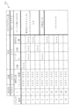
- FIG. 5 shows an example of the procedure manual 111. As shown in FIG. 5, the procedure manual 111 records, for example, information on the order recipient, product number, product name, and name of the NC program 73 of the workpiece W to be machined at the top.
- the holder number which is the identification number of the tool, the name of the tool used, the number of blades of the tool, the nose R, the blade length, and the protrusion amount are recorded. These pieces of information are recorded line by line. Each line corresponds to each of the machining processes. Therefore, information such as the holder number is associated with each process and recorded line by line.
- the procedure manual 111 records supplementary information such as information on how to attach the workpiece W and information on the malfunction that occurred.
- a user writes the above information in a paper procedure manual and stores it as a paper document.
- the control device 22 creates an electronic data procedure manual 111 based on the setting information detected from the image data of the imaging device 56, and executes a process of registering the created procedure manual 111 in the procedure manual data 106.
- the control device 22 creates the procedure manual 111 when the machining of the planned number of workpieces W has been completed.
- the control device 22 detects the type of tool and the tool protrusion amount based on the imaging data of the imaging device 56.
- the control device 22 also detects the order of the processes for machining the workpiece W, the tool number T of the tool used in each process, and the holder number of the tool used based on the NC program 73 used for the machining.
- the control device 22 creates the procedure manual 111 by associating each piece of detected information.
- the memory device 72 stores the manufacturer's model number as information on the type of tool.
- the information on the type of tool is also associated with the tool number T corresponding to that tool.
- the control device 22 enters the tool number T and tool used columns of the procedure manual 111 based on this information.
- the control device 22 displays the format of the procedure manual 111 shown in FIG. 5 on the touch panel 61, for example, and inputs the detected information into each item. This allows the holder number, tool number T, tool used (type of tool), and protrusion amount to be automatically input. This reduces the burden on the user in creating the procedure manual 111. It also reduces the occurrence of writing errors.
- the control device 22 may also automatically input information that can be detected from the imaging data of the imaging device 56, such as the number of teeth of the tool, nose R, and blade length, in addition to the protrusion amount, and that can be left as the procedure manual 111, into the procedure manual 111.
- the control device 22 may also input the program name of the NC program 73 used for machining into the program name field of the procedure manual 111.
- the control device 22 also accepts information such as the order recipient, product number, and installation method on the touch panel 61, inputs it into the procedure manual 111, and registers the completed procedure manual 111 in the procedure manual data 106.
- the control device 22 may also accept corrections to automatically input items (such as the holder number) on the touch panel 61.
- the control device 22 may also execute printing of the created procedure manual 111.
- the control device 22 may also accept information on the order recipient and product number on the touch panel 61, and search for and display the procedure manual 111 from the procedure manual data 106 based on the accepted information. This allows the user to easily search for and reuse the required procedure manual 111.
- the image data captured by the imaging device 56 may be used for purposes other than setting the above-mentioned setting information.
- the control device 22 may display the image data captured by the imaging device 56 on the touch panel 61 in real time.
- the user may want to view the inside of the machining chamber to check for interference, such as during the first machining operation after a setup change.
- the control device 22 may capture an image of the inside of the machining chamber with the imaging device 56 and display the captured image on the touch panel 61. This allows the user to understand the condition inside the machining chamber from the image.
- the work spindle device 11 is an example of a work holding device.
- the turret device 12 is an example of a processing device.
- the control device 22 is an example of a processing device.
- the cutting tool 33 is an example of a tool.
- the imaging device 56 is an example of an acquisition device.
- the touch panel 61 is an example of a user interface.
- the NC program 73 is an example of a processing program.
- the control device 22 sets setting information required for creating an NC program 73 for controlling machining operations based on the image data captured by the image capture device 56. This allows setting information such as the size of the base material, the protrusion amount of the base material, the type of tool, and the protrusion amount of the tool to be set based on the image data. As a result, the setting information required for creating the NC program 73 can be automatically acquired and set.
- the contents of the present disclosure are not limited to the above-described embodiments, but can be embodied in various forms with various modifications and improvements based on the knowledge of those skilled in the art.
- the configuration of the machine tool 10 in the above embodiment is just an example.
- the machine tool 10 may be configured to include a 3D scanner or a touch sensor instead of the imaging device 56.
- the machine tool 10 may not be configured to include the tool setter 57.
- the control device 22 may be configured not to output CAD data based on the imaging data.
- the machine tool 10 is not limited to a turret-type lathe, and may be, for example, a machining center.
- the machine tool 10 may perform imaging of a tool attached to a tool head or a tool stored in an ATC by the imaging device 56, and detect the type and protrusion amount of the tool.
- the contents, order, etc. of the procedure for creating the NC program 73 shown in FIG. 4 are merely an example and can be changed as appropriate.
- the imaging device 56 is configured to be capable of acquiring both the attachment state of the workpiece W in the work spindle device 11 and the attachment state of the tool in the turret device 12, but is not limited to this.
- the imaging device 56 may be configured to be capable of capturing an image of only one of the two attachment states, i.e., only one of the two attachment states.
- control device 22 may be configured to be capable of setting only the setting information related to the workpiece W (base material) or the setting information related to the tool.
- the machining program of the present disclosure is not limited to the NC program 73, but may be another machining program capable of controlling the machine tool 10.
- Machine tool 11 Work spindle device (work holding device), 12 Turret device (machining device), 22 Control device (processing device), 32 Chuck jaws, 33 Cutting tool (tool), 56 Imaging device (acquisition device), 57 Tool setter, 61 Touch panel (user interface), 73 NC program (machining program), 105 Jaw database, 111 Procedure manual, W Work.
Landscapes
- Engineering & Computer Science (AREA)
- Physics & Mathematics (AREA)
- Geometry (AREA)
- Human Computer Interaction (AREA)
- Manufacturing & Machinery (AREA)
- General Physics & Mathematics (AREA)
- Automation & Control Theory (AREA)
- Mechanical Engineering (AREA)
- Machine Tool Sensing Apparatuses (AREA)
Abstract
加工プログラムの作成に必要な設定情報を取得できる工作機械を提供すること。 工作機械は、ワークを保持するワーク保持装置と、ワーク保持装置に保持されたワークに対する加工を実行する工具を取り付け可能な加工装置と、ワーク保持装置におけるワークの取付状態、及び加工装置における工具の取付状態のうち、少なくとも一方の取付状態を取得可能な取得装置と、取得装置により取得した取付状態に基づいて、加工動作を制御する加工プログラムの作成に必要な設定情報を設定する処理装置と、を備える。
Description
本開示は、工作機械の状態を取得する技術に関するものである。
下記特許文献1には、ワークから情報を取得する加工装置について記載されている。特許文献1の加工装置は、ステージ上に載置されたワークを撮像装置によって撮像し、ワークに設けられたバーコードを読み取っている。加工装置は、読み取ったバーコードからワークに関する情報としてワークの材質等を取得している。
上記した特許文献1の工作機械は、ステージ上のワークに、砥石を当てて研削を実行する構成となっている。しかしながら、工作機械の構成によっては必要となる情報が異なっており、情報を取得する点において改善の余地があった。
本開示は、上記の課題に鑑みてなされたものであり、加工プログラムの作成に必要な設定情報を取得できる工作機械を提供することを目的とする。
上記課題を解決するために、本明細書は、ワークを保持するワーク保持装置と、前記ワーク保持装置に保持された前記ワークに対する加工を実行する工具を取り付け可能な加工装置と、前記ワーク保持装置における前記ワークの取付状態、及び前記加工装置における前記工具の取付状態のうち、少なくとも一方の取付状態を取得可能な取得装置と、前記取得装置により取得した取付状態に基づいて、加工動作を制御する加工プログラムの作成に必要な設定情報を設定する処理装置と、を備える工作機械、を開示する。
本開示の工作機械によれば、取得装置によって、ワーク保持装置におけるワークの取付状態、及び加工装置における工具の取付状態のうち、少なくとも一方の取付状態を取得できる。処理装置は、取得装置により取得した取付状態に基づいて、加工動作を制御する加工プログラムの作成に必要な設定情報を設定する。これにより、ワークの取付状態であれば、加工前の母材の大きさや母材の突き出し量などの設定情報を、取得装置により取得した取得状態に基づいて設定できる。また、工具の取付状態であれば、工具の種類、工具の突き出し量などの設定情報を、取得装置により取得し取得状態に基づいて設定できる。その結果、加工プログラムの作成に必要な設定情報を、自動で取得し設定を行うことができる。
以下、本開示の工作機械を具体化した一実施例について、図面を参照しつつ詳しく説明する。図1は、本実施例の工作機械10を正面側から見た斜視図を示している。図2は、本実施例に係る工作機械10のブロック図を示している。尚、図1は、工作機械10の装置カバー等の図示を省略している。また、図1に示すように、後述するワーク主軸装置11の主軸に沿った方向をZ軸方向、Z軸方向に直交しタレット装置12を案内面19に沿って移動させる方向をX軸方向、X軸方向及びZ軸方向に直交する方向をY軸方向と称して説明する。
図1及び図2に示すように、工作機械10は、例えば、タレット装置12の回転軸がZ軸と平行なタレット旋盤である。工作機械10は、ワーク主軸装置11、タレット装置12、X軸スライド装置13、Z軸スライド装置14、ロボット15(図2参照)、基台となるベッド16、操作盤20(図2参照)、制御装置22(図2参照)、撮像装置56、ツールセッタ57を備えている。尚、図1及び図2に示す工作機械10の構成は、一例である。例えば、工作機械10は、ワーク主軸装置11及びタレット装置12を複数組備える旋盤でも良く、旋盤に加えて工具主軸装置を備える、所謂、複合加工機でも良い。従って、本開示の工作機械としては、旋盤に限らず、例えば、マシニングセンタ、フライス盤、ボール盤など、工具を備えることが可能な様々な構成の工作機械を採用できる。また、工作機械10は、ロボット15を備えない構成でも良い。
図1に示すように、ベッド16には、上方に開口した箱型の切り屑回収部17が形成され、工作物であるワークWの加工によって発生する切り屑を切り屑回収部17に回収する。また、ベッド16は、装置手前の切り屑回収部17に向けて傾斜した案内面19を有するスラント型のベッドである。
ワーク主軸装置11は、ベッド16に対して固定され、主軸台23と、回転装置24を備えている。主軸台23は、ワークWを保持(把持)するチャック機構28を取り付け可能となっている。チャック機構28は、ワークWを保持する機構として、例えば、ワークWを着座させる当て金31と、当て金31に着座したワークWをチャックする複数のチャック爪32を備えている。尚、ワークWを保持するチャック機構28としては、チャック爪32を用いる機構に限らず、コレットチャックなどの他の構成の機構を採用できる。チャック機構28は、駆動源としてエアシリンダや油圧シリンダを備えており、工作機械10の制御装置22(図2参照)の制御に基づいて駆動源を駆動し、チャック爪32を開閉する。主軸台23は、切り屑回収部17の上方となる位置で、チャック機構28によりワークWを保持する。ワーク主軸装置11は、チャック機構28で保持したワークWを、Z軸方向と平行なワーク主軸を中心に回転させる。尚、ワーク主軸装置11は、主軸台23が固定された構成に限らず、主軸台23をベッド16に対してZ軸方向等にスライド移動させる構成でも良い。
また、主軸台23の内部には、主軸(図示略)が軸受によって回転自在に支持されている。Z軸方向における主軸の一端側(タレット装置12側)には、チャック機構28が取り付けられ、他端側には主軸側プーリ25が取り付けられている。回転装置24は、主軸サーボモータ26と、タイミングベルト27を備えている。主軸サーボモータ26は、主軸を回転させる駆動源として機能し、工作機械10の制御装置22(図2参照)の制御に基づいて回転動作を制御される。タイミングベルト27は、主軸サーボモータ26の出力軸に取り付けられたモータ側プーリ30と、主軸側プーリ25とに掛け渡されている。これにより、主軸は、主軸サーボモータ26の回転力を、タイミングベルト27を介して伝達され、主軸サーボモータ26の回転に応じて回転する。制御装置22は、主軸サーボモータ26に取り付けられた主軸エンコーダ29(図2参照)の回転位置情報に基づいた制御により、主軸の回転速度や回転位置を制御する。
タレット装置12は、タレット本体部41と、タレット43を備えている。タレット本体部41は、箱形形状をなし、ベッド16の傾斜した案内面19に配置されている。タレット43は、タレット本体部41における主軸台23側の面に回転可能に取り付けられ、複数の工具を取り付け可能となっている。尚、図1は、工具を取り外した状態のタレット43を示している。また、図1に示すタレット43には、ワークWをワーク主軸装置11側へ押すプッシャ51が取り付けられている。
図3は、工具をタレット43に取り付けた状態の拡大図を示している。尚、図3は、チャック機構28(図1参照)をワーク主軸装置11から取り外した状態を示している。図3に示すように、タレット43は、Z軸方向に所定の厚みを有し、例えば、Z軸方向から見た形状が略正10角形をなしている。タレット43は、10個の辺及びその周囲に工具を取り付け可能な工具取付部45が形成されている。工具取付部45は、タレット43におけるワーク主軸装置11側の面やタレット43の外周面に工具等を取り付け可能な構造を有している。図3に示す例では、工具として切削工具33が取り付けられている。工具取付部45には、切削工具33、エンドミルやドリルなどの回転工具、あるいはプッシャ51(図1参照)が着脱可能に取り付けられる。以下の説明では、切削工具33や回転工具を総称して説明する場合、工具と記載する。
タレット43には、回転方向34において所定の回転角度ごとに工具取付部45が設けられている。本実施例のタレット43は、36度ごとに工具取付部45が設けられ、合計で10個の工具取付部45が設けられている。工具取付部45には、第1取付部35と、第2取付部36が設けられている。第1取付部35は、タレット43の外周面に形成された平面を有し、ボルトやネジなどの螺合部材38を螺合する被螺合部35Aが形成されている。切削工具33は、ホルダ37によって第1取付部35に取り付けられる。切削工具33は、刃先33Aと、チップ33Bと、シャンク33Cを有している。シャンク33Cは、ホルダ37によって第1取付部35に固定される。ホルダ37は、螺合部材38によって所定の第1取付部35(工具取付部45)に固定される。第1取付部35に取り付けられる切削工具33のシャンク33Cは、Z軸方向に長い略円柱や略四角柱の部材であり、第1取付部35に取り付けられる場合、基端部をホルダ37に挿入した状態でホルダ37によって保持される。例えば、シャンク33Cは、ホルダ37に螺合したボルトによってZ軸方向における位置を固定される。シャンク33Cは、このボルトを緩めることで、ホルダ37に対してZ軸方向に相対的に移動可能となる。シャンク33Cの先端部の刃先33Aには、チップ33Bが着脱可能に取り付けられる。チップ33Bは、ボルトやネジなどの螺合部材39によって刃先33Aに固定される。
また、タレット43は、第2取付部36にも、切削工具33を取り付けることができる。第2取付部36には、タレット43の半径方向に沿って形成された溝が形成されている。第2取付部36に切削工具33を取り付ける場合、シャンク33Cは、クランパ40によって第2取付部36に取り付けられる。クランパ40は、シャンク33Cの基端部とともに第2取付部36の溝に挿入され、螺合部材40Aを螺合されている。クランパ40は、例えば、クサビ形状の調整部材(所謂、ライナ)とともに第2取付部36の溝に挿入され、螺合部材40Aを螺合する量に応じてシャンク33Cを挟持する力を変更される。従って、シャンク33Cは、螺合部材40Aを螺合することによって、クランパ40とともに溝に嵌め込まれ半径方向における位置を固定される。第2取付部36に取り付ける切削工具33のシャンク33Cは、半径方向に長い略四角柱の部材であり、基端部をクランパ40によって保持されている。シャンク33Cの先端部の刃先33Aには、螺合部材39によってチップ33Bが着脱可能に取り付けられる。従って、切削工具33は、刃先33Aに対してチップ33Bが着脱可能な所謂スローアウェイバイトである。ユーザは、交換が必要となった寿命チップについて切削工具33の螺合部材39を緩めてチップ33B,を交換する。
また、タレット装置12は、例えば、タレット本体部41にタレット用サーボモータ47(図2参照)が内蔵されている。タレット装置12は、制御装置22によってタレット用サーボモータ47の回転動作を制御され、タレット43をZ軸方向と平行な方向に沿った回転軸を中心に回転させる。タレット装置12は、タレット43を回転させ作業位置に割り出す工具(切削工具33など)を変更し、作業位置に割り出した工具を用いてワーク主軸装置11に保持されたワークWに対する加工を実行する。また、タレット用サーボモータ47は、タレット43を回転させることに加え、タレット43に取り付けた回転工具(エンドミルなど)を回転させるための駆動源として機能する。制御装置22は、例えば、タレット用サーボモータ47を制御することで、タレット43の旋回割出しや、タレット43に取り付けられた回転工具の回転を実行する。尚、タレット装置12は、旋回用の駆動源とは別に、回転工具を回転させる駆動源を備える構成でも良い。また、タレット43は、回転工具を取り付けることができず、切削工具のみを取り付け可能な構成でも良い。
図1及び図2に示すように、X軸スライド装置13及びZ軸スライド装置14は、タレット装置12(作業位置の工具)の位置を変更する装置である。Z軸スライド装置14は、例えば、ワーク主軸と平行なZ軸方向(ワークWに接近する方向又はワークWから離間する方向)へタレット装置12を移動させる装置である。X軸スライド装置13は、X軸方向、即ち、Z軸方向と直交する方向へタレット装置12を移動させる装置である。
Z軸スライド装置14は、Z軸案内レール52と、Z軸スライダ53とを備えている。Z軸案内レール52は、ベッド16の案内面19に配置され、Z軸方向と平行な方向に延びている。Z軸スライダ53は、Z軸案内レール52に対してスライド移動可能に取り付けられている。Z軸スライド装置14は、Z軸サーボモータ14A(図2参照)を備え、Z軸サーボモータ14Aの回転出力を、伝達機構(例えば、ボールネジ機構など)を介してZ軸スライダ53に伝達し、Z軸スライダ53をZ軸方向に移動させる。
また、Z軸スライド装置14は、Z軸サーボモータ14Aの回転位置等のエンコーダ情報を出力するZ軸エンコーダ14Bを備えている。制御装置22は、Z軸エンコーダ14Bのエンコーダ情報(回転位置情報など)に基づいてZ軸サーボモータ14Aの回転速度等を制御するフィードバック制御を実行する。制御装置22は、Z軸サーボモータ14Aを制御し、Z軸スライダ53をZ軸方向における任意の位置へ移動させる。
また、X軸スライド装置13は、X軸案内レール54と、X軸スライダ(図示略)とを備えている。X軸案内レール54は、Z軸スライダ53の上に配置され、X軸方向と平行な方向に配設され、X軸スライダをX軸方向へスライド移動可能に保持する。X軸スライド装置13は、X軸サーボモータ13Aを備え、X軸サーボモータ13Aの回転出力を、伝達機構(例えば、ボールネジ機構など)を介してX軸スライダに伝達し、X軸スライダをX軸方向に移動させる。
また、X軸スライド装置13は、X軸サーボモータ13Aのエンコーダ情報を出力するX軸エンコーダ13Bを備えている。制御装置22は、X軸エンコーダ13Bのエンコーダ情報に基づいてX軸サーボモータ13Aの回転速度等を制御するフィードバック制御を実行する。制御装置22は、X軸サーボモータ13Aを制御し、X軸スライダをX軸方向における任意の位置へ移動させる。
X軸スライダの上には、タレット装置12が搭載されている。従って、制御装置22は、X軸スライド装置13及びZ軸スライド装置14を制御することで、タレット43(割り出した工具やプッシャ51)をX軸方向及びZ軸方向の任意の位置に移動させることができる。尚、上記したスライド装置の構成は、一例である。例えば、工作機械10は、互いに直交するXYZの3軸方向へタレット43を移動させるスライド装置を備えても良い。また、方向の定義は、工作機械10の構成に応じて適宜変更される。また、Z軸スライダ53やX軸スライダの位置情報(スライド位置)を検出する方法は、エンコーダを用いる方法に限らない。制御装置22は、リニアスケールなどの他の位置検出装置を用いて、Z軸スライダ53やX軸スライダのスライド位置を検出しても良い。
ロボット15は、例えば、ガントリ式のワーク搬送装置(ローダとも言い得る)である。尚、図1は、ロボット15の図示を省略している。ロボット15は、ワークWを把持する把持部(チャック爪など)を有するヘッドを備えている。また、ロボット15は、例えば、工作機械10に取り付けられたレール台を備え、工作機械10における左右方向、上下方向、前後方向の各方向と平行な方向に沿ってヘッドを移動させることができる。ロボット15は、ヘッドの把持部によって、例えば、ワークWを搬入する入口装置、ワーク主軸装置11、ワークWを搬出する出口装置、ワークWの形状を検査する検測装置、ワークWを反転させるワーク反転装置等(共に図示略)との間でワークWの受け渡しを実行する。
操作盤20は、例えば、タッチパネル61や複数の操作スイッチ62を備え、工作機械10に関する情報の表示や動作指示の受け付けなどを実行する。操作盤20は、例えば、図示しない工作機械10の装置カバーの前面に設けられている。操作盤20は、本開示のユーザインタフェースの一例である。尚、本開示のユーザインタフェースは、タッチパネル61のような表示装置と入力装置の両方を備える構成に限らない。例えば、ユーザインタフェースは、液晶装置と、液晶装置に表示された項目を選択等する物理スイッチを備える構成でも良い。また、工作機械10は、操作盤20以外のユーザインタフェース、例えば、ティーチングペンダントなどの携帯型のユーザインタフェースを備えても良い。そして、工作機械10は、携帯型のユーザインタフェースによってユーザからの操作入力を受け付けても良い。
また、撮像装置56は、タレット43、工具、ワークW、チャック機構28等を撮像する装置である。撮像装置56は、カメラ58、可動部59(図2参照)、反射抑制部60(図2参照)を備えている。カメラ58は、CCDやCMOSなどの撮像素子を有し、制御装置22の制御に基づいて撮像を実行し、撮像データを制御装置22へ出力する。撮像データは、2次元データでも良く、3次元データでも良い。制御装置22は、カメラ58で撮像した撮像データを、タレット43における工具の取付状態や、ワーク主軸装置11におけるワークWの取付状態として取得し、取得した撮像データ(取得状態)に基づいて設定情報を設定する。設定する設定情報の詳細については後述する。また、カメラ58は、照明を備えており、制御装置22の制御に基づいて照明のオン・オフや照明の光の強さを変更可能となっている。
可動部59は、カメラ58の撮像方向や、カメラ58と対象物との間の距離を変更する装置である。対象物とは、例えば、工具、チャック爪32、ワークWなどであり、取付状態を撮像する対象となるものである。可動部59としては、例えば、XYZの各軸方向と平行な方向にカメラ58を移動させるスライド機構、及びXYZの各軸周りにカメラ58を回転させる回転機構を採用することができる。従って、可動部59としては、対象物における所望の部分を所望の角度から撮像するために、カメラ58の位置や角度を変更し、撮像位置、撮像範囲、撮像方向を変更できる装置を採用することができる。
反射抑制部60は、例えば、偏光フィルタや、偏光フィルタを回転させる回転機構を備えている。工作機械10の加工室内では、照明や金属のカバーによる反射が発生し、ハレーションが発生する虞がある。例えば、ユーザは、各撮像位置で撮像した撮像データを確認し、各撮像位置について予め偏光フィルタの回転角度を設定する。制御装置22は、撮像位置と、その撮像位置での偏光フィルタの回転角度を関連付けて記憶装置72に記憶する。制御装置22は、任意の撮像位置で撮像を実行する場合、その撮像位置に応じて予め設定された偏光フィルタの回転角度を記憶装置72から読み出し、読み出した回転角度に応じて反射抑制部60の回転機構を制御して、設定値の回転角度に偏光フィルタを調整する。これにより、撮像データから対象物(ワークW等)を検出する精度を向上させることができる。尚、制御装置22は、撮像データを画像処理し、画像処理の結果に基づいて偏光フィルタの回転角度を自動で調整しても良い。また、制御装置22は、照明の光の強さ、カメラ58のシャッター時間等を自動で調整しても良い。
撮像装置56は、本開示の取得装置の一例である。撮像装置56は、上記した構成に限らない。例えば、工作機械10は、工具を撮像する撮像装置56とは別に、ワークWを撮像する撮像装置56を備えても良い。即ち、工作機械10は、複数の撮像装置56を備えても良い。また、加工室内には、ミスト・水滴・切り粉などが飛散する。このため、撮像装置56は、飛散物をカメラ58から排除するワイパーや、飛散物からカメラ58を保護するシャッターなどを備えても良い。
また、工具やワークの取付状態を取得する取得装置は、カメラ58(撮像装置56)に限らない。例えば、本開示の取得装置は、工具やワークWの形状等を検出可能なセンサでも良い。具体的には、赤外線やレーザーを用いた3Dスキャナー、超音波、マイクロ波などを用いる非接触式のセンサでも良い。あるいは、取得装置は、リミットスイッチ、作動トランス(コイル)などを用いた接触式センサでも良い。また、取得装置としてセンサを採用する場合、カメラ58の場合と同様に、取得装置は、センサの検出方向を変更する可動部59を備えても良い。また、取得装置は、カメラ58とセンサを組み合わせた構成でも良い。
また、ツールセッタ57は、工具の刃先を検出する装置である。ツールセッタ57は、例えば、アーム57A、刃先検出センサ57B、センサ駆動部57C(図2参照)を備えている。アーム57Aは、加工室内において、主軸台23の下方から主軸台23の前方に向かって伸びている。刃先検出センサ57Bは、接触式のセンサであり、アーム57Aの先端に設けられている。刃先検出センサ57Bは、工具の刃先(チップ33Bの刃先など)との接触に応じた検出信号を制御装置22に出力する。これにより、制御装置22は、接触を検出したタイミングにおける刃先のXZ座標に基づいて、工具の突き出し量を検出することができる。センサ駆動部57Cは、例えば、基端部を中心にアーム57Aを回転させる回転機構である。センサ駆動部57Cは、アーム57Aを回転させ、工具の刃先に接触する検出位置と、工具やワークWから退避した退避位置とに、刃先検出センサ57Bの位置を切り替える。
また、制御装置22は、数値制御装置65と、PLC66を備えている。数値制御装置65は、CPU71と、記憶装置72とを備えている。PLC66は、CPU81と、記憶装置82とを備えている。記憶装置72,82は、例えば、RAM、ROM、フラッシュメモリ、HDD等を備えている。尚、記憶装置72,82の構成は、上記した構成に限らず、HDDに替えてSSDを備える構成でも良く、USBメモリなどの外部記憶装置、DVD-RAMなどの記憶メディアを備える構成でも良く、あるいはこれらを組み合わせた構成でも良い。
また、工作機械10は、制御装置22と、上記した各装置(ワーク主軸装置11、タレット装置12、X軸スライド装置13、Z軸スライド装置14、ロボット15、操作盤20、撮像装置56、ツールセッタ57)の各々を接続する複数の駆動回路67を備えている。制御装置22は、各装置と駆動回路67を介して電気的に接続され、各装置を制御可能となっている。駆動回路67は、例えば、X軸スライド装置13のX軸サーボモータ13Aやロボット15の駆動源のモータに接続された駆動回路67であれば、各モータ(サーボモータなど)に供給する電力(三相交流の電流など)を、制御装置22の指示信号(移動量、移動先の位置、移動速度、目標トルクなど)に基づいて変更するドライバ回路(サーボアンプ)である。また、駆動回路67は、例えば、操作盤20に接続された駆動回路67であれば、操作盤20から入力した信号の増幅等を実行するアンプ回路である。
また、記憶装置72には、ワーク主軸装置11、タレット装置12、X軸スライド装置13、Z軸スライド装置14、ロボット15などの動作を数値制御する複数のNCプログラム73が記憶されている。数値制御装置65は、NCプログラム73をCPU71で実行し、NCプログラム73に記述された数値指令に従って、駆動回路67(ドライバ回路)に指示信号を出力して制御する。駆動回路67は、例えば、各サーボモータ(X軸サーボモータ13Aなど)に取り付けられたエンコーダ(X軸エンコーダ13Bなど)のエンコーダ情報と、制御装置22の指示信号に基づいて三相交流の電流を変更するフィードバック制御を実行し、処理の完了等を数値制御装置65に適宜通知する。これにより、制御装置22は、数値制御装置65による数値制御に基づいて所望の位置へタレット43(工具)やロボット15のヘッド等を各軸方向に沿ってスライド移動させる。尚、各装置をスライド移動させる駆動源としては、サーボモータに限らず、ステッピングモータやリニアモータなどの他の駆動源を採用することもできる。
また、本実施例では、制御装置22は、後述する基準データ104、爪データベース105、手順書データ106を記憶装置72に記憶する。尚、制御装置22は、基準データ104、爪データベース105、手順書データ106を、記憶装置72以外の記憶装置に記憶しても良い。例えば、制御装置22は、基準データ104等を、PLC66の記憶装置82や、工作機械10と接続された外部記憶装置などに記憶しても良い。
PLC66は、Programmable Logic Controllerである。記憶装置82には、各種の信号を処理するラダー回路を構築するためのラダープログラム83が記憶されている。PLC66は、CPU81でラダープログラム83を実行し、ラダープログラム83に基づくシーケンス処理によって、例えば、工作機械10が備える各種のランプ等の素子へ出力信号を出力して駆動する処理、リミットスイッチなどの素子から入力信号を入力する処理を実行する。また、PLC66は、例えば、通信バス69を介して数値制御装置65と接続され、数値制御装置65との間で通信可能となっている。PLC66は、ラダープログラム83に基づいて構築したデバイス85を用いて数値制御装置65との間で信号の入出力を実行する。デバイス85は、例えば、CPU81でラダープログラム83を実行することで記憶装置82上に構築される記憶領域であり、工作機械10が備える外部I/O(センサなど)の信号の値を記憶するデバイス、数値制御装置65とやり取りするための信号の値を記憶するためのデバイス、設定値を記憶するキープリレーを実現するデバイスなどである。これにより、PLC66は、工作機械10が備える外部I/Oと、数値制御装置65との間の信号の中継(入出力)を実行する。
また、記憶装置72には、NCプログラム73の他に、登録プログラム75、その他の加工に必要な各種のデータなど(図示略)が記憶されている。登録プログラム75は、撮像装置56やツールセッタ57によって取得した取得状態に基づいて設定情報を設定する。尚、以下の説明では、制御装置22が登録プログラム75をCPU71で実行して各装置を制御することを、単に装置名で記載する場合がある。例えば、「制御装置22は、撮像装置56による撮像を実行する」とは、「制御装置22は、登録プログラム75をCPU71で実行し、駆動回路67を介して撮像装置56を制御することで、カメラ58によって撮像を実行する」ことを意味している。
(取付状態の取得、設定情報の設定について)
ここで、NCプログラム73を作成する方法としては、例えば、「Gコード等のコードを直接入力する方法」、「対話式機能により入力する方法」、「CADCAMシステムにより変換する方法」がある。図4は、NCプログラム73を作成する流れを示している。上記した3つのどの作成方法においても、図4に示すステップ(以下、単にSと記載する)1~S7の流れで作成することができる。また、図4は、設定情報について手入力を行う比較例(図4の左側)と、本実施例(図4の右側)を対比させて図示している。
ここで、NCプログラム73を作成する方法としては、例えば、「Gコード等のコードを直接入力する方法」、「対話式機能により入力する方法」、「CADCAMシステムにより変換する方法」がある。図4は、NCプログラム73を作成する流れを示している。上記した3つのどの作成方法においても、図4に示すステップ(以下、単にSと記載する)1~S7の流れで作成することができる。また、図4は、設定情報について手入力を行う比較例(図4の左側)と、本実施例(図4の右側)を対比させて図示している。
例えば、ユーザは、工作機械10のタッチパネル61を操作して、S1において、加工前の母材について設定情報を登録する。次に、ユーザは、S2において、使用する工具の情報を登録する。次に、ユーザは、S3において、登録した工具の中から、タレット43の各工具取付部45(ホルダ番号)に取り付ける工具を選択し、工具とホルダ番号との関連付けを行う。ここでいうホルダ番号とは、複数の工具取付部45を識別する番号である。次に、ユーザは、S4において、加工工程の順序を設定する。次に、ユーザは、S5において、S4で設定した各工程における加工条件を設定する。加工条件とは、例えば、ワークWの単位時間当たりの回転数(回転速度)、使用する工具、送りの量などである。次に、ユーザは、S6において、寸法値(切削径など)を設定する。これにより、NCプログラム73を作成するための設定情報を登録し、NCプログラム73を作成することができる。そして、ユーザは、S7において、シミュレーションを実行し、作成したNCプログラム73の各工程においてワークWと工具の干渉が発生していないかなどを確認する。尚、上記したS1~S7の各ステップの内容や処理の順番は一例である。
S1~S2においては、設定項目(母材のサイズなど)が多数存在する。このため、比較例のように手入力で設定しようとすると、設定作業の作業負担が増加する。設定情報をGコードのパラメータとして入力する場合、対話式機能により入力する場合、あるいは、CADCAMシステムのパラメータとして取り込む場合の何れにおいても作業負担が増加する。また、ワークWや工具の設定情報(工具の幅や突き出し量など)は、加工精度に影響するため、例えば、小数点代まで正確に入力する必要がある。このため、手入力では、数値や桁数の入力ミスが発生する虞がある。さらに、1台の工作機械10で複数種の工具を使用し、変種変量に対応することもあり、生産するワークWの種類を変更する所謂、段取り替えも頻繁に発生することもある。段取り替えの度に設定情報の入力が発生し、作業ミスを生じさせる虞がある。
これに対し、本実施例の制御装置22は、図4の機能1に示すように、撮像装置56の撮像データ(取付状態)に基づいて、ワークWや工具の大きさ等を取得し、上記した設定情報として自動で設定する。取付状態を取得する対象物としては、例えば、ワークW、チャック爪32、治具、工具(刃先33A、チップ33B、シャンク33Cなど)、ホルダ37等がある。このため、撮像装置56は、これらの対象物を撮像するため、可動部59によって撮像方向や撮像位置を変更可能となっている。尚、工作機械10は、複数の撮像装置56を備え、上記した対象物のそれぞれを撮像可能に複数の撮像装置56を設置した構成でも良い。
制御装置22は、撮像装置56の撮像データに基づいて、ワークWの設定情報を取得する。具体的には、制御装置22は、撮像データに基づいて、例えば、加工前の母材のサイズ(大きさ、長さ)、母材の突き出し量を取得し、取得した値を、NCプログラム73を作成するための設定情報として設定する。母材の突き出し量とは、例えば、チャック機構28の当て金31に着座した母材がチャック爪32からはみ出している量(長さ)である。
ユーザは、例えば、段取り替えに応じて、次の加工で使用するチャック機構28(チャック爪32や当て金31)、母材、ホルダ37、切削工具33等を取り付けた後、タッチパネル61を操作して設定情報の取得と登録を工作機械10に指示する。制御装置22は、タッチパネル61を介してユーザから指示を受け付けると、CPU71で登録プログラム75を実行し、可動部59を制御して撮像装置56を各撮像位置に配置する。制御装置22は、可動部59を制御して撮像方向を調整し、反射抑制部60を制御して偏光フィルタの回転角度を調整して、チャック機構28や母材を撮像する。制御装置22(登録プログラム75)は、撮像データを画像処理して母材サイズや母材の突き出し量を取得する。制御装置22は、取得した値を、上記したNCプログラム73の作成における設定情報として設定する。これにより、NCプログラム73のコードの変数や、コードから読み出すパラメータ等を登録できる。取得した設定情報は、NCプログラム73の作成だけでなく、工作機械10の設定値(オフセット値、補正値など)に用いても良い。後述する工具の取付状態から取得した設定情報についても同様である。
撮像データから母材サイズ等の設定情報を取得する方法としては、様々な方法を採用できる。例えば、制御装置22は、画像処理によって、チャック爪32や母材の外縁(エッジ)を撮像データから検出し、母材サイズや突き出し量等を検出しても良い。あるいは、制御装置22は、工作機械10の機械原点や撮像装置56のスライド位置(撮像位置)に基づいて母材のサイズ等を検出しても良い。
同様に、制御装置22は、撮像データに基づいて工具の設定情報を取得する。具体的には、制御装置22は、例えば、工具の種類、チップの種類、工具の幅、工具の突き出し量、ノーズR、切り込み角、刃先角を取得し、取得した値を、NCプログラム73を作成するための設定情報として設定する。あるいは、工具として回転工具がタレット43に取り付けられている場合、制御装置22は、例えば、ドリルの種類、ドリル径、ドリルの突き出し量、ドリルの振れ量を取得しても良い。また、制御装置22は、チャック機構28やタレット43に用いられる治具の種類等を、撮像データから取得しても良い。工具(切削工具33や回転工具)の突き出し量とは、例えば、基準となる位置から各工具の刃先の位置までの距離(ずれ量)を示す値であり、NCプログラム73において刃先の位置を調整する量(設定値、オフセット値)である。
撮像データから工具等の設定情報を取得する方法としては、様々な方法を採用できる。例えば、図2に示すように、記憶装置72には、工具やチップ33Bの種類を判断するための基準となる基準データ104が記憶されている。図3に示すように、例えば、タレット43に取り付けられたシャンク33C、刃先33Aの各々は、加工する位置(外形、内径)、形状、目的などに応じて構造が異なっている。このため、基準データ104には、工具(刃先33A、チップ33B、シャンク33C)などの形状のデータが記憶されている。この形状のデータは、2次元のデータでも良く、3次元のデータでも良い。また、形状のデータは、予め工具を撮像した撮像データでも良く、工具メーカが作成したCADデータ等でも良い。また、基準データ104は、登録プログラム75とは別のデータではなく、登録プログラム75のデータの一部でも良い。そして、制御装置22は、画像処理によって撮像データから検出した工具の全体形状やチップ33B等の一部の形状と、基準データ104に含まれる形状データの形状を比較し、一致する形状データを見つけ出すことで、工具の種類、チップの種類等を検出する。また、制御装置22は、工具の幅や回転工具(ドリルなど)の径などの他の設定情報を、撮像データを画像処理することで取得しても良い。また、制御装置22は、ノーズR、切り込み角、刃先角などのチップ33Bの形状や角度を、撮像データを画像処理することで取得しても良い。
また、図3に示すように、チップ33Bの各々は、タレット43に対してZ軸方向やX軸方向において相対的に異なる保持位置に保持される。このため、仮に、工具の割り出しの際に、Z軸方向及びX軸方向における同じ位置にタレット43をスライド移動させ、チップ33Bの各々を同じ回転位置に割り出しても、チップ33Bの刃先の各々は、異なる位置(XZ座標)に配置される。例えば、制御装置22は、Z軸方向における基準となる位置からチップ33Bの刃先までの長さLを、撮像データから取得する。制御装置22は、取得した長さLに基づいて、NCプログラム73において刃先の位置を調整する量(突き出し量)を設定する。これにより、作業位置に割り出した工具の刃先を、Z軸方向において同じ位置に配置することができる。尚、X軸方向においても、同様に、撮像データから調整量を取得し設定することで同一位置に配置できる。
尚、上記した設定情報の取得方法や取得する設定情報の内容は、一例である。例えば、制御装置22は、切削工具33を工具取付部45に取り付けるホルダ37の種類を、撮像データから取得しても良い。また、制御装置22は、図4に示すS3における工具の種類と、タレット43の各工具取付部45(ホルダ番号)との関連付けを自動で実行しても良い。上記したように、制御装置22は、撮像データに基づいて工具の種類を取得できる。制御装置22は、取得した工具の種類と、割り出し位置に割り出した工具取付部45のホルダ番号とを関連付ける。これにより、複数の工具取付部45の各々に、実際にどの種類の工具が取り付けられているのかを自動で検出し設定できる。
また、制御装置22は、撮像データに基づいて工具(チップ33B)の摩耗量を検出し、補正値として用いても良い。また、制御装置22は、上記したように、取得装置としてセンサ(3Dスキャナーなど)を用いる場合、センサを用いて上記したワークWや工具の取付状態を取得し(センシングし)、取得状態に基づいて設定情報(種類、位置、形状など)を検出・設定しても良い。また、制御装置22は、撮像装置56で取得した情報と、ユーザから入力された情報との正誤判定を実行しても良い。例えば、制御装置22は、ユーザから入力された母材サイズが、撮像データから取得した母材サイズと一致するか否かを判断し、一致した場合はユーザの入力値を設定情報として設定し、一致しない場合はエラーを通知しても良い。これにより、入力ミスを抑制でき、誤って入力した場合は、確認・検討をユーザに促すことができる。
上記したように、撮像装置56は、ワーク主軸装置11におけるワークWの取付状態を撮像することが可能である。制御装置22は、撮像装置56により取得した撮像データに基づいて、ワークW(母材)のサイズ、及びチャック機構28に保持された状態のワークWの突き出し量を検出しNCプログラム73の設定情報として設定する。
また、撮像装置56は、タレット43における工具の取付状態を撮像することが可能である。制御装置22は、撮像装置56により取得した撮像データに基づいて、工具の種類等を検出しNCプログラム73の設定情報として設定する。これにより、ワークWや工具の設定情報について、ユーザによる手入力の手間を減らし、入力ミスの発生を抑制することが可能となる。
また、上記したように、制御装置22は、撮像データに基づいて、工具の種類や突き出し量等を検出する。しかしながら、突き出し量の情報は、0.数mm等の細かい単位まで検出・設定することが好ましい。しかしながら、クーラントや切り粉の影響によって撮像データから突き出し量を検出する精度が低下する虞がある。そこで、制御装置22は、突き出し量などの高い精度が要求される設定情報についてはツールセッタ57を用いた検出を実行しても良い。
例えば、制御装置22は、撮像データに基づいて工具の種類を取得し、ツールセッタ57を用いて突き出し量を取得しても良い。制御装置22は、撮像装置56による撮像を実行し、撮像データと基準データ104とのマッチングにより工具の種類を検出する。次に、制御装置22は、ツールセッタ57のセンサ駆動部57Cを制御して、工具の刃先に接触する検出位置に刃先検出センサ57Bを配置し、工具の刃先の位置をツールセッタ57により検出する。制御装置22は、例えば、刃先と接触したことを示す検出信号をツールセッタ57から入力したタイミングにおけるタレット43のXZ座標に基づいて刃先の位置を検出し、検出した刃先の位置に基づいて工具の突き出し量を設定する。制御装置22は、設定した突き出し量をNCプログラム73の設定情報として設定する。これにより、撮像装置56とツールセッタ57を併用して設定情報を設定できる。クーラントや切り粉の影響で撮像装置56による認識率が低下する場合など、接触式のツールセッタ57を併用して設定情報の精度を向上できる。尚、ツールセッタ57によって検出する情報は、突き出し量に限らず、工具の幅などの他の情報でも良い。
(S7:シミュレーションの環境構築について)
また、ユーザは、機内の干渉をチェックする目的でS7のシミュレーションを実行する。例えば、CADCAMシステムを用いてシミュレーションを実行する場合、シミュレーション環境を構築するために、実機と同じチャック爪32、工具、ワークW等を、CADCAMシステムに登録する必要がある。仮に、登録ミスにより実環境とシミュレーション環境に差異が生じると、シミュレーション環境で干渉しなかったにも関わらず、実環境で干渉が発生する虞がある。
また、ユーザは、機内の干渉をチェックする目的でS7のシミュレーションを実行する。例えば、CADCAMシステムを用いてシミュレーションを実行する場合、シミュレーション環境を構築するために、実機と同じチャック爪32、工具、ワークW等を、CADCAMシステムに登録する必要がある。仮に、登録ミスにより実環境とシミュレーション環境に差異が生じると、シミュレーション環境で干渉しなかったにも関わらず、実環境で干渉が発生する虞がある。
そこで、本実施例の制御装置22は、図4の機能2に示すように、撮像装置56により撮像した撮像データに基づいて、シミュレーション環境で使用可能なデータを出力する機能を有している。具体的には、上記したように、撮像装置56は、ワーク主軸装置11におけるワークWの取付状態、及びタレット43における工具の取付状態の両方を撮像可能となっている。ワーク主軸装置11は、ワークWをチャックするチャック爪32を取り付け可能であり、ワークWの種類に応じてチャック爪32を変更可能となっている。制御装置22は、撮像装置56により撮像した撮像データに基づいて、ワークWの形状、チャック爪32の形状、及び工具の形状のCADデータを出力する。例えば、撮像装置56として3Dカメラを備える場合、制御装置22は、ワークWを撮像した3D映像から3DのCADデータを生成し出力しても良い。これにより、ユーザは、制御装置22から出力されたCADデータを、CADCAMシステムのPC等に読み取らせ登録することで、シミュレーション環境の構築における登録作業の負担を軽減できる。また、撮像データから自動で取得したCADデータを用いることで、登録ミスの発生を抑制し、実環境とシミュレーション環境の差異をなくすことができる。また、制御装置22は、ワークWの形状と同様に、チャック爪32の形状、及び工具の形状を、3DのCADデータとして出力する。尚、制御装置22は、ワークWの形状、チャック爪32の形状、及び工具の形状の3つの形状についてCADデータを出力しなくとも良い。制御装置22は、3つの形状のうち、少なくとも1つの形状のCADデータを出力可能な構成でも良い。
また、制御装置22が出力するデータの形式としては、CADCAMシステムなどのシミュレーションを実行するシステムの環境で読み取り可能な形式のデータであれば適宜採用できる。例えば、制御装置22は、2Dのカメラ58でワークW等を撮影し、2次元の撮像データからエッジの点群データを検出して2Dや3DのCADデータを生成しても良い。また、制御装置22は、CADデータを生成しなくとも良い。例えば、各種類のチャック爪32や工具のCADデータを予め記憶装置72に記憶しても良い。また、チャック爪32のCADデータ等を、チャック爪32等の種類を示す識別情報と関連付けて記憶しても良い。そして、制御装置22は、撮像装置56の撮像データに基づいて実際に取り付けられたチャック爪32等の種類を検出する。制御装置22は、検出したチャック爪32等の種類と一致する種類のCADデータを、記憶装置72から見つけ出し出力しても良い。
また、工作機械10からCADCAMシステムにデータを伝送する方法は、特に限定されない。例えば、工作機械10と、CADCAMシステムとがネットワークで接続されている場合、制御装置22は、CADデータを、ネットワークを介してCADCAMシステムに送信しても良い。また、工作機械10と、CADCAMシステムとが接続されていない場合、制御装置22は、CADデータを、USBメモリ等の外部記録媒体に出力しても良い。また、制御装置22は、シミュレーションに必要な他の情報(NCプログラム73など)を、CADデータとともに出力しても良い。このNCプログラム73としては、上記した設定情報に基づいて、コードの入力や対話式機能により作成したものを用いることができる。
また、図4の機能2に示すように、上記したCADデータの出力によって、シミュレーション環境に登録できる(取り込める)情報としては、上記したワークWや工具の形状以外に、以下の情報を登録することが可能である。例えば、チャック爪32のCADデータを出力することで、CADCAMシステム側では、CADデータから、チャック爪32の種類や形状を登録できる。また、ワークWやチャック機構28のCADデータを出力することで、ワークサイズ、ワークWの突き出し量、チャック機構28に用いる治具の種類等を登録できる。また、タレット43や工具のCADデータを出力することで、工具の種類、ホルダ37の種類、各工具のホルダ番号を登録することができる。尚、これらの情報を、CADCAMシステム側で検出して登録しなくとも良い。例えば、制御装置22は、上記したチャック機構28の種類の情報を、CADデータとは別に文字情報として出力し、チャック機構28の種類を文字情報からCADCAMシステムに読み込ませても良い。
また、シミュレーションをCADCAMシステム以外の装置が実行しても良い。例えば、制御装置22は、撮像データから取得したチャック爪32、ワークW、工具の形状・大きさや、各工程における部材の位置に基づいて、各部材の干渉を判断しても良い。即ち、工作機械10でシミュレーションを実行しても良い。従って、シミュレーションを実行する装置やシミュレーションの方法は、適宜変更可能である。
(爪データベース105について)
次に、爪データベース105について説明する。チャック爪32は、例えば、ワークWの直径が数mm違うだけで異なるのものを使用する可能性がある。極端な場合、チャック爪32の種類は、ワークWの種類ごとに異なる。このため、ユーザは、非常に多くのチャック爪32(小爪)を管理する必要が生じる。上記したように、制御装置22は、撮像データに基づいてワークWやチャック爪32の形状や種類などを検出することができる。そこで、制御装置22は、撮像データに基づいて、ワークWの形状及びチャック爪32の種類を検出し、検出したワークWの形状とチャック爪32の種類とを関連付けて爪データベース105に記憶する。
次に、爪データベース105について説明する。チャック爪32は、例えば、ワークWの直径が数mm違うだけで異なるのものを使用する可能性がある。極端な場合、チャック爪32の種類は、ワークWの種類ごとに異なる。このため、ユーザは、非常に多くのチャック爪32(小爪)を管理する必要が生じる。上記したように、制御装置22は、撮像データに基づいてワークWやチャック爪32の形状や種類などを検出することができる。そこで、制御装置22は、撮像データに基づいて、ワークWの形状及びチャック爪32の種類を検出し、検出したワークWの形状とチャック爪32の種類とを関連付けて爪データベース105に記憶する。
具体的には、制御装置22は、加工前の母材(ワークW)の形状(外径、軸方向の長さ、凹凸、穴など)を撮像データから検出する。また、制御装置22は、チャック爪32の形状を撮像データから検出し、検出した形状と基準データ104に基づいてチャック爪32の種類を判断する。そして、制御装置22は、母材の形状と、チャック爪32の種類の情報を関連付けて爪データベース105に登録する。登録するタイミングは、特に限定されない。制御装置22は、例えば、タッチパネル61を介してユーザから指示を受け付けたタイミングで登録を実行しても良い。あるいは、制御装置22は、生産予定の生産数だけワークWの加工が完了したタイミングで検出・登録を実行しても良い。これにより、過去の加工で使用したチャック爪32とワークWの情報を関連付けて、爪データベース105に蓄積することができる。使用したチャック爪32やワークWを、後から確認することができる。尚、制御装置22は、加工前の母材ではなく、加工後のワークWの形状を、チャック爪32の種類と関連付けて爪データベース105に登録しても良い。
また、次回以降に加工を実行する場合に、使用するワークWの種類と、チャック爪32の種類とが適切な組み合わせであるのかを、爪データベース105により判断できる。例えば、ユーザは、段取り替え後に使用するチャック機構28(チャック爪32)をワーク主軸装置11に取り付け、母材をチャック爪32でチャックさせた状態で、組み合わせが正しいか確認する指示をタッチパネル61で実行する。制御装置22は、上記したタッチパネル61に対する指示(本開示の操作入力の一例)を受け付けると、撮像装置56の撮像データに基づいて、母材の形状と、チャック爪32の種類を検出し、検出した組み合わせが爪データベース105に登録されているか否かを判断する。制御装置22は、例えば、検出したチャック爪32の種類と爪データベース105で関連付けられていた母材の形状が、撮像データから検出した形状と一致した場合、組み合わせが正しい旨をタッチパネル61に表示する。一方、制御装置22は、検出したチャック爪32の種類と爪データベース105で関連付けられていた母材の形状が、撮像データから検出した形状と一致しない場合、エラーをタッチパネル61に表示する。これにより、誤った組み合わせの準備をしていた場合、母材やチャック爪32の種類が正しいか、ユーザに確認させることができる。母材とチャック爪32の組み合わせを間違えたまま加工を開始してしまうこと抑制できる。また、ユーザのチャック爪32を管理する負担を軽減できる。また、制御装置22は、検出したチャック爪32の種類や、母材の形状が爪データベース105に登録されていなかった場合、未登録である旨をタッチパネル61に表示しても良い。
尚、爪データベース105に記憶するデータは上記したデータに限らない。例えば、母材の形状ではなく、母材の突き出し量を、爪データベース105に登録しても良い。そして、制御装置22は、ユーザが準備したチャック爪32と母材とにおける突き出し量を撮像データから検出し、爪データベース105の突き出し量と比較しても良い。即ち、爪データベース105に登録するデータとしては、ワークWとチャック爪32との組み合わせが正しいか否かを判断できる様々なデータを採用できる。また、制御装置22は、ユーザからチャック爪32の収納場所の情報を受け付け、受け付けた収納場所の情報を、チャック爪32と関連付けて爪データベース105に登録しても良い。これにより、制御装置22は、撮像データから検出した母材の形状と、爪データベース105に基づいて、適切なチャック爪32の収納場所をタッチパネル61等で通知できる。
(手順書データ106について)
次に、手順書データ106について説明する。本実施例の制御装置22は、手順書の作成や手順書を手順書データ106に登録する機能を有する。手順書とは、過去のワークWの加工に関する情報を記録したものであり、対象のワークWを加工した時の工作機械10の状態を記録したものである。図5は、手順書111の一例を示している。図5に示すように、手順書111には、例えば、加工対象のワークWの受注先、品番、品名、NCプログラム73の名前の情報が上部に記録されている。また、手順書111には、受注先等の下に、ホルダ番号、工具の識別番号であるツール番号T、使用工具の名前、工具の刃数、ノーズR、刃長、突き出し量が記録されている。これらの情報は、1行ずつ記録されている。各行は、加工工程の1つ1つに対応している。従って、ホルダ番号等の情報は、工程ごとに関連付けられ、1行ずつ記録されている。また、手順書111には、ワークWの取り付け方の情報や、発生した不具合の情報など、補足事項が記録されている。
次に、手順書データ106について説明する。本実施例の制御装置22は、手順書の作成や手順書を手順書データ106に登録する機能を有する。手順書とは、過去のワークWの加工に関する情報を記録したものであり、対象のワークWを加工した時の工作機械10の状態を記録したものである。図5は、手順書111の一例を示している。図5に示すように、手順書111には、例えば、加工対象のワークWの受注先、品番、品名、NCプログラム73の名前の情報が上部に記録されている。また、手順書111には、受注先等の下に、ホルダ番号、工具の識別番号であるツール番号T、使用工具の名前、工具の刃数、ノーズR、刃長、突き出し量が記録されている。これらの情報は、1行ずつ記録されている。各行は、加工工程の1つ1つに対応している。従って、ホルダ番号等の情報は、工程ごとに関連付けられ、1行ずつ記録されている。また、手順書111には、ワークWの取り付け方の情報や、発生した不具合の情報など、補足事項が記録されている。
一般的には、ユーザは、紙の手順書に上記した情報を書き込んで、紙の資料として保管する。ユーザは、同じワークWの加工を実行する際に、保管場所から手順書を出して参照し段取り替えを実行する。しかしながら、手書きであるため、記載ミスや記載漏れが発生し、次の加工時に適切な段取り替えを実施できない虞がある。そこで、制御装置22は、撮像装置56の撮像データから検出した設定情報に基づいて、電子データの手順書111を作成し、作成した手順書111を手順書データ106に登録する処理を実行する。
例えば、制御装置22は、生産予定の生産数だけワークWの加工が完了したタイミングで、手順書111の作成を実行する。制御装置22は、撮像装置56の撮像データに基づいて工具の種類や工具の突き出し量を検出する。また、制御装置22は、加工に使用したNCプログラム73に基づいて、ワークWを加工する工程の順番と、各工程で使用した工具のツール番号T、使用した工具のホルダ番号を検出する。制御装置22は、検出した各情報を関連付けて手順書111を作成する。例えば、記憶装置72には、工具の種類の情報として、メーカの型番が記憶されている。また、工具の種類の情報は、その工具に対応するツール番号Tと関連付けられている。制御装置22は、この情報に基づいて、手順書111のツール番号T、使用工具の欄を入力する。
制御装置22は、例えば、図5に示す手順書111のフォーマットをタッチパネル61に表示し、検出した情報を各項目に入力する。これにより、ホルダ番号、ツール番号T、使用工具(工具の種類)、突き出し量を自動で入力することができる。ユーザが手順書111を作成する作業の負担を軽減できる。また、記載ミスの発生を抑制できる。また、制御装置22は、突き出し量に限らず、工具の刃数、ノーズR、刃長など、撮像装置56の撮像データから検出でき、手順書111として残せる情報を手順書111に自動で入力しても良い。また、制御装置22は、加工に使用したNCプログラム73のプログラム名を、手順書111のプログラム名の欄に入力しても良い。また、制御装置22は、タッチパネル61において、受注先、品番、取り付け方の情報などを受け付け、手順書111に入力し、完成した手順書111を手順書データ106に登録する。また、制御装置22は、自動で入力した項目(ホルダ番号など)の修正を、タッチパネル61で受け付けても良い。また、制御装置22は、作成した手順書111の印刷を実行しても良い。また、制御装置22は、受注先や品番の情報をタッチパネル61で受け付け、受け付けた情報に基づいて手順書データ106から手順書111を検索し表示しても良い。これにより、ユーザは、必要な手順書111を簡単に検索して流用できる。
尚、撮像装置56の撮像データを、上記した設定情報の設定以外の目的に利用しても良い。例えば、制御装置22は、撮像装置56で撮像した撮像データを、タッチパネル61にリアルタイムで表示しても良い。ユーザは、段取り替え後の1回目の加工時など、干渉が起こらないか加工室内を見たい場合がある。しかしながら、覗き窓の位置や大きさによっては、工具やチャック爪32が、クーラント等によって見れない場合がある。そこで、制御装置22は、撮像装置56で加工室内を撮影し、撮影した映像をタッチパネル61に表示しても良い。これにより、ユーザは、映像によって加工室内の状態を把握することができる。
以下に、本実施例の用語と請求の範囲に記載した用語との対応関係について説明する。上記実施例において、ワーク主軸装置11は、ワーク保持装置の一例である。タレット装置12は、加工装置の一例である。制御装置22は、処理装置の一例である。切削工具33は、工具の一例である。撮像装置56は、取得装置の一例である。タッチパネル61は、ユーザインタフェースの一例である。NCプログラム73は、加工プログラムの一例である。
以上、上記した本実施例では、以下の効果を奏する。
本願の一態様である制御装置22は、撮像装置56の撮像データに基づいて、加工動作を制御するNCプログラム73の作成に必要な設定情報を設定する。これによれば、母材の大きさ、母材の突き出し量、工具の種類、工具の突き出し量などの設定情報を、撮像データに基づいて設定できる。その結果、NCプログラム73の作成に必要な設定情報を、自動で取得し設定を行うことができる。
本願の一態様である制御装置22は、撮像装置56の撮像データに基づいて、加工動作を制御するNCプログラム73の作成に必要な設定情報を設定する。これによれば、母材の大きさ、母材の突き出し量、工具の種類、工具の突き出し量などの設定情報を、撮像データに基づいて設定できる。その結果、NCプログラム73の作成に必要な設定情報を、自動で取得し設定を行うことができる。
また、本開示の内容は、上記実施例に限定されるものではなく、当業者の知識に基づいて種々の変更、改良を施した種々の態様で実施することが可能である。
例えば、上記実施例の工作機械10の構成は、一例である。例えば、工作機械10は、撮像装置56に代えて、3Dスキャナーやタッチセンサを備える構成でも良い。また、工作機械10は、ツールセッタ57を備えない構成でも良い。また、制御装置22は、撮像データに基づくCADデータを出力できない構成でも良い。
また、工作機械10は、タレット式の旋盤に限らず、例えば、マシニングセンタでも良い。この場合、工作機械10は、工具ヘッドに取り付けられた工具や、ATCに収納された工具について、撮像装置56による撮像を実行し、工具の種類や、突き出し量を検出しても良い。
また、図4に示すNCプログラム73の作成手順の内容、順番等は一例であり、適宜変更可能である。
また、上記実施例では、撮像装置56は、ワーク主軸装置11におけるワークWの取付状態、及びタレット装置12における工具の取付状態の両方を取得可能な構成であったが、これに限らない。撮像装置56は、2つの取付状態のうち、どちらか一方の取付状態のみを、即ち、どちらか一方のみを撮像可能な構成でも良い。この場合、制御装置22は、ワークW(母材)に関する設定情報又は工具に関する設定情報のみを設定できる構成でも良い。
また、本開示の加工プログラムは、NCプログラム73に限らず、工作機械10を制御可能な他の加工プログラムでも良い。
尚、本開示の内容は、請求項に記載の従属関係に限定されない。例えば、請求項4において「請求項1に記載の工作機械」を「請求項1から請求項3の何れか1項に記載の工作機械」に変更した技術思想についても、本明細書は開示している。また、例えば、請求項5において「請求項1又は請求項2に記載の工作機械」を「請求項1から請求項4の何れか1項に記載の工作機械」に変更した技術思想についても、本明細書は開示している。また、例えば、請求項6において「請求項1又は請求項2に記載の工作機械」を「請求項1から請求項5の何れか1項に記載の工作機械」に変更した技術思想についても、本明細書は開示している。また、例えば、請求項7において「請求項1又は請求項2に記載の工作機械」を「請求項1から請求項6の何れか1項に記載の工作機械」に変更した技術思想についても、本明細書は開示している。
10 工作機械、11 ワーク主軸装置(ワーク保持装置)、12 タレット装置(加工装置)、22 制御装置(処理装置)、32 チャック爪、33 切削工具(工具)、56 撮像装置(取得装置)、57 ツールセッタ、61 タッチパネル(ユーザインタフェース)、73 NCプログラム(加工プログラム)、105 爪データベース、111 手順書、W ワーク。
Claims (8)
- ワークを保持するワーク保持装置と、
前記ワーク保持装置に保持された前記ワークに対する加工を実行する工具を取り付け可能な加工装置と、
前記ワーク保持装置における前記ワークの取付状態、及び前記加工装置における前記工具の取付状態のうち、少なくとも一方の取付状態を取得可能な取得装置と、
前記取得装置により取得した取付状態に基づいて、加工動作を制御する加工プログラムの作成に必要な設定情報を設定する処理装置と、
を備える工作機械。 - 前記取得装置は、
前記加工装置における前記工具の取付状態を取得可能であり、
前記処理装置は、
前記取得装置により取得した取付状態に基づいて、前記工具の種類を検出し、検出した前記工具の種類の情報を前記設定情報として設定する、請求項1に記載の工作機械。 - 前記工具の刃先に接触し前記刃先の位置を検出するツールセッタを、さらに備え、
前記取得装置は、
撮像装置であり、
前記処理装置は、
前記ツールセッタの検出情報に基づいて前記工具の突き出し量を検出し、検出した前記工具の突き出し量の情報を前記設定情報として設定する、請求項2に記載の工作機械。 - 前記取得装置は、
前記ワーク保持装置における前記ワークの取付状態を取得可能であり、
前記処理装置は、
前記取得装置により取得した取付状態に基づいて、前記ワークのサイズ、及び前記ワーク保持装置に保持された状態の前記ワークの突き出し量を検出し、検出した情報を前記設定情報として設定する、請求項1に記載の工作機械。 - 前記取得装置は、
撮像装置であり、前記ワーク保持装置における前記ワークの取付状態、及び前記加工装置における前記工具の取付状態の両方を撮像可能であり、
前記ワーク保持装置は、
前記ワークをチャックするチャック爪を取り付け可能であり、前記ワークの種類に応じて前記チャック爪を変更可能であり、
前記処理装置は、
前記撮像装置により撮像した撮像データに基づいて、前記ワークの形状、前記チャック爪の形状、及び前記工具の形状のうち、少なくとも1つの形状を示すCADデータを出力する、請求項1又は請求項2に記載の工作機械。 - 前記取得装置は、
前記加工装置における前記工具の取付状態を取得可能であり、
前記処理装置は、
前記取得装置により取得した取付状態に基づいて検出した前記工具の種類及び前記工具の突き出し量を、前記ワークを加工する工程の順番に関連付けて記載した手順書を作成する、請求項1又は請求項2に記載の工作機械。 - 前記取得装置は、
前記ワーク保持装置における前記ワークの取付状態、及び前記加工装置における前記工具の取付状態の両方を取得可能であり、
前記ワーク保持装置は、
前記ワークをチャックするチャック爪を取り付け可能であり、前記ワークの種類に応じて前記チャック爪を変更可能であり、
前記処理装置は、
前記取得装置により取得した取付状態に基づいて、前記ワークの形状及び前記チャック爪の種類を検出し、検出した前記ワークの形状と前記チャック爪の種類とを関連付けて爪データベースに記憶する、請求項1又は請求項2に記載の工作機械。 - ユーザインタフェースを、さらに備え、
前記処理装置は、
前記ワーク保持装置における前記ワークの取付状態、及び前記加工装置における前記工具の取付状態の両方を、前記取得装置により取得し、前記ユーザインタフェースに対する操作入力に基づいて、取得した取付状態から検出した前記ワークの形状と、前記チャック爪の種類との組み合わせが、前記爪データベースに登録されているか否かを判断し、前記ユーザインタフェースを介して判断結果を報知する、請求項7に記載の工作機械。
Priority Applications (1)
| Application Number | Priority Date | Filing Date | Title |
|---|---|---|---|
| PCT/JP2023/030300 WO2025041297A1 (ja) | 2023-08-23 | 2023-08-23 | 工作機械 |
Applications Claiming Priority (1)
| Application Number | Priority Date | Filing Date | Title |
|---|---|---|---|
| PCT/JP2023/030300 WO2025041297A1 (ja) | 2023-08-23 | 2023-08-23 | 工作機械 |
Publications (1)
| Publication Number | Publication Date |
|---|---|
| WO2025041297A1 true WO2025041297A1 (ja) | 2025-02-27 |
Family
ID=94731660
Family Applications (1)
| Application Number | Title | Priority Date | Filing Date |
|---|---|---|---|
| PCT/JP2023/030300 Pending WO2025041297A1 (ja) | 2023-08-23 | 2023-08-23 | 工作機械 |
Country Status (1)
| Country | Link |
|---|---|
| WO (1) | WO2025041297A1 (ja) |
Citations (4)
| Publication number | Priority date | Publication date | Assignee | Title |
|---|---|---|---|---|
| JP2005025668A (ja) * | 2003-07-02 | 2005-01-27 | Kanehira:Kk | 形状加工方法及び形状加工プログラム |
| JP2019185545A (ja) * | 2018-04-13 | 2019-10-24 | ファナック株式会社 | 数値制御システム |
| JP2020032475A (ja) * | 2018-08-28 | 2020-03-05 | ファナック株式会社 | 工具識別装置及び工具識別システム |
| JP2020071703A (ja) * | 2018-10-31 | 2020-05-07 | 株式会社三井ハイテック | 加工装置及び加工方法 |
-
2023
- 2023-08-23 WO PCT/JP2023/030300 patent/WO2025041297A1/ja active Pending
Patent Citations (4)
| Publication number | Priority date | Publication date | Assignee | Title |
|---|---|---|---|---|
| JP2005025668A (ja) * | 2003-07-02 | 2005-01-27 | Kanehira:Kk | 形状加工方法及び形状加工プログラム |
| JP2019185545A (ja) * | 2018-04-13 | 2019-10-24 | ファナック株式会社 | 数値制御システム |
| JP2020032475A (ja) * | 2018-08-28 | 2020-03-05 | ファナック株式会社 | 工具識別装置及び工具識別システム |
| JP2020071703A (ja) * | 2018-10-31 | 2020-05-07 | 株式会社三井ハイテック | 加工装置及び加工方法 |
Similar Documents
| Publication | Publication Date | Title |
|---|---|---|
| CN106346315B (zh) | 能够取得工件原点的机床控制系统以及工件原点设定方法 | |
| US7218995B2 (en) | Device and method for workpiece calibration | |
| JP5725796B2 (ja) | 工具の測定方法及び測定装置、並びに工作機械 | |
| CN104423322B (zh) | 机床的刀具偏移值的自动设定装置及自动设定方法 | |
| KR101161496B1 (ko) | 날끝 위치 검출 방법 및 날끝 위치 검출 장치 | |
| CN106925997B (zh) | 一种自动钻铣系统及方法、钻铣生产线 | |
| JP7068317B2 (ja) | 工作機械を制御する方法 | |
| JP2016093872A (ja) | 工作機械の工具補正値の自動設定装置及び自動設定方法 | |
| JP3333681B2 (ja) | 刃先位置計測装置 | |
| JP6496338B2 (ja) | 工作機械の制御システム | |
| WO2014132845A1 (ja) | 工具形状測定方法及び工具形状測定装置 | |
| JPH0852638A (ja) | 干渉チェック方法および加工プログラムチェック方法および加工適否チェック方法 | |
| US12330253B2 (en) | Processing machine and production method for object subject to processing | |
| JP6709280B2 (ja) | 機械加工モジュール、機械加工モジュールのためのアクセサリ・アセンブリ、及び、機械加工モジュールを始動するための方法 | |
| WO2019066034A1 (ja) | 工作機械の機上測定方法および制御装置 | |
| CN104768706A (zh) | 加工程序生成方法及装置 | |
| WO2021049186A1 (ja) | 工具検査システム | |
| JP4180469B2 (ja) | 工作機械の加工適否チェック方法 | |
| WO2020012871A1 (ja) | 工作機械 | |
| CN113953850A (zh) | 一种针对固定直径圆环类工件加工设备 | |
| AU2019211984B2 (en) | Machine tool and method for preparing processing of a material-removing rotational tool | |
| WO2025041297A1 (ja) | 工作機械 | |
| JP2021163107A (ja) | 数値制御装置と数値制御装置の制御方法 | |
| JP2008070143A (ja) | 光学式測定システム | |
| JP5072743B2 (ja) | マイクロマシンおよびマイクロフライスマシン |
Legal Events
| Date | Code | Title | Description |
|---|---|---|---|
| 121 | Ep: the epo has been informed by wipo that ep was designated in this application |
Ref document number: 23949755 Country of ref document: EP Kind code of ref document: A1 |
|
| ENP | Entry into the national phase |
Ref document number: 2025541243 Country of ref document: JP Kind code of ref document: A |
|
| WWE | Wipo information: entry into national phase |
Ref document number: 2025541243 Country of ref document: JP |
|
| NENP | Non-entry into the national phase |
Ref country code: DE |