WO2025041297A1 - Machine-outil - Google Patents
Machine-outil Download PDFInfo
- Publication number
- WO2025041297A1 WO2025041297A1 PCT/JP2023/030300 JP2023030300W WO2025041297A1 WO 2025041297 A1 WO2025041297 A1 WO 2025041297A1 JP 2023030300 W JP2023030300 W JP 2023030300W WO 2025041297 A1 WO2025041297 A1 WO 2025041297A1
- Authority
- WO
- WIPO (PCT)
- Prior art keywords
- tool
- workpiece
- mounting state
- control device
- imaging
- Prior art date
- Legal status (The legal status is an assumption and is not a legal conclusion. Google has not performed a legal analysis and makes no representation as to the accuracy of the status listed.)
- Pending
Links
Images

Classifications
-
- B—PERFORMING OPERATIONS; TRANSPORTING
- B23—MACHINE TOOLS; METAL-WORKING NOT OTHERWISE PROVIDED FOR
- B23Q—DETAILS, COMPONENTS, OR ACCESSORIES FOR MACHINE TOOLS, e.g. ARRANGEMENTS FOR COPYING OR CONTROLLING; MACHINE TOOLS IN GENERAL CHARACTERISED BY THE CONSTRUCTION OF PARTICULAR DETAILS OR COMPONENTS; COMBINATIONS OR ASSOCIATIONS OF METAL-WORKING MACHINES, NOT DIRECTED TO A PARTICULAR RESULT
- B23Q15/00—Automatic control or regulation of feed movement, cutting velocity or position of tool or work
-
- G—PHYSICS
- G05—CONTROLLING; REGULATING
- G05B—CONTROL OR REGULATING SYSTEMS IN GENERAL; FUNCTIONAL ELEMENTS OF SUCH SYSTEMS; MONITORING OR TESTING ARRANGEMENTS FOR SUCH SYSTEMS OR ELEMENTS
- G05B19/00—Program-control systems
- G05B19/02—Program-control systems electric
- G05B19/18—Numerical control [NC], i.e. automatically operating machines, in particular machine tools, e.g. in a manufacturing environment, so as to execute positioning, movement or co-ordinated operations by means of program data in numerical form
- G05B19/4093—Numerical control [NC], i.e. automatically operating machines, in particular machine tools, e.g. in a manufacturing environment, so as to execute positioning, movement or co-ordinated operations by means of program data in numerical form characterised by part programming, e.g. entry of geometrical information as taken from a technical drawing, combining this with machining and material information to obtain control information, named part program, for the NC machine
-
- B—PERFORMING OPERATIONS; TRANSPORTING
- B23—MACHINE TOOLS; METAL-WORKING NOT OTHERWISE PROVIDED FOR
- B23Q—DETAILS, COMPONENTS, OR ACCESSORIES FOR MACHINE TOOLS, e.g. ARRANGEMENTS FOR COPYING OR CONTROLLING; MACHINE TOOLS IN GENERAL CHARACTERISED BY THE CONSTRUCTION OF PARTICULAR DETAILS OR COMPONENTS; COMBINATIONS OR ASSOCIATIONS OF METAL-WORKING MACHINES, NOT DIRECTED TO A PARTICULAR RESULT
- B23Q17/00—Arrangements for observing, indicating or measuring on machine tools
- B23Q17/24—Arrangements for observing, indicating or measuring on machine tools using optics or electromagnetic waves
Definitions
- This disclosure relates to technology for acquiring the status of machine tools.
- Patent Document 1 describes a processing device that acquires information from a workpiece.
- the processing device in Patent Document 1 uses an imaging device to capture an image of the workpiece placed on a stage and reads the barcode on the workpiece.
- the processing device acquires information about the workpiece, such as the material of the workpiece, from the read barcode.
- the machine tool in Patent Document 1 mentioned above is configured to perform grinding by applying a grinding wheel to a workpiece placed on a stage.
- the information required differs depending on the configuration of the machine tool, and there is room for improvement in terms of acquiring the information.
- This disclosure was made in consideration of the above problems, and aims to provide a machine tool that can acquire the setting information necessary to create a machining program.
- this specification discloses a machine tool that includes a work holding device that holds a workpiece, a processing device capable of mounting a tool that performs processing on the workpiece held by the work holding device, an acquisition device that can acquire at least one of the mounting states of the workpiece in the work holding device and the mounting state of the tool in the processing device, and a processing device that sets setting information required to create a processing program that controls the processing operation based on the mounting states acquired by the acquisition device.
- the acquisition device can acquire at least one of the attachment states of the workpiece in the work holding device and the attachment state of the tool in the processing device.
- the processing device sets the setting information required to create a processing program that controls the processing operation based on the attachment state acquired by the acquisition device.
- setting information such as the size of the base material before processing and the protrusion amount of the base material can be set based on the acquired state acquired by the acquisition device.
- setting information such as the type of tool and the protrusion amount of the tool can be acquired by the acquisition device and set based on the acquired state.
- the setting information required to create the processing program can be automatically acquired and set.
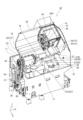
- FIG. 1 is a perspective view of a machine tool according to an embodiment.
- Block diagram of a machine tool A close-up of the turret with tooling attached.
- 1A and 1B are diagrams for explaining a comparative example and an embodiment in the flow of creating a program. A diagram showing the procedure manual.
- Fig. 1 shows a perspective view of the machine tool 10 of this embodiment as seen from the front side.
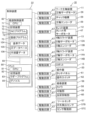
- Fig. 2 shows a block diagram of the machine tool 10 according to this embodiment. Note that Fig. 1 does not show the device cover of the machine tool 10. As shown in Fig.
- the direction along the spindle of the work spindle device 11 described later is referred to as the Z-axis direction
- the direction perpendicular to the Z-axis direction and in which the turret device 12 moves along the guide surface 19 is referred to as the X-axis direction
- the direction perpendicular to the X-axis and Z-axis directions is referred to as the Y-axis direction.
- the machine tool 10 is, for example, a turret lathe in which the rotation axis of the turret device 12 is parallel to the Z axis.
- the machine tool 10 is equipped with a work spindle device 11, a turret device 12, an X-axis slide device 13, a Z-axis slide device 14, a robot 15 (see FIG. 2), a bed 16 serving as a base, an operation panel 20 (see FIG. 2), a control device 22 (see FIG. 2), an imaging device 56, and a tool setter 57.
- the configuration of the machine tool 10 shown in FIG. 1 and FIG. 2 is an example.
- the machine tool 10 may be a lathe equipped with multiple sets of work spindle devices 11 and turret devices 12, or may be a so-called multi-tasking machine equipped with a tool spindle device in addition to a lathe. Therefore, the machine tool disclosed herein is not limited to a lathe, and machine tools of various configurations that can be equipped with tools, such as a machining center, a milling machine, and a drill press, can be used.
- the machine tool 10 may also be configured without the robot 15.
- the bed 16 is formed with a box-shaped chip collection section 17 that opens upward, and chips generated during the machining of the workpiece W are collected in the chip collection section 17.
- the bed 16 is a slant-type bed that has a guide surface 19 that is inclined toward the chip collection section 17 in front of the device.
- the work spindle device 11 is fixed to the bed 16 and includes a headstock 23 and a rotating device 24.
- the headstock 23 can be fitted with a chuck mechanism 28 that holds (grabs) the workpiece W.
- the chuck mechanism 28 includes, for example, a backing plate 31 for seating the workpiece W and a number of chuck jaws 32 for chucking the workpiece W seated on the backing plate 31 as a mechanism for holding the workpiece W.
- the chuck mechanism 28 for holding the workpiece W is not limited to a mechanism using the chuck jaws 32, and other mechanisms such as a collet chuck can be used.
- the chuck mechanism 28 includes an air cylinder or hydraulic cylinder as a drive source, and drives the drive source based on the control of the control device 22 (see FIG.
- the headstock 23 holds the workpiece W by the chuck mechanism 28 at a position above the chip collection section 17.
- the work spindle device 11 rotates the work W held by the chuck mechanism 28 around a work spindle parallel to the Z-axis direction. Note that the work spindle device 11 is not limited to a configuration in which the headstock 23 is fixed, and may be configured so that the headstock 23 slides relative to the bed 16 in the Z-axis direction, etc.
- the shank 33C is fixed to the first mounting portion 35 by the holder 37.
- the holder 37 is fixed to a predetermined first mounting portion 35 (tool mounting portion 45) by a threaded member 38.
- the shank 33C of the cutting tool 33 attached to the first attachment portion 35 is a member shaped like a generally cylindrical or rectangular column that is long in the Z-axis direction.
- the base end is inserted into the holder 37 and held by the holder 37.
- the position of the shank 33C in the Z-axis direction is fixed by a bolt screwed into the holder 37. By loosening this bolt, the shank 33C can move relative to the holder 37 in the Z-axis direction.
- a tip 33B is detachably attached to the cutting edge 33A at the tip of the shank 33C.
- the tip 33B is fixed to the cutting edge 33A by a screw member 39 such as a bolt or a screw.
- the turret device 12 has, for example, a turret servo motor 47 (see FIG. 2) built into the turret body 41.
- the rotational operation of the turret servo motor 47 is controlled by the control device 22, and the turret device 12 rotates the turret 43 around a rotation axis parallel to the Z-axis direction.
- the turret device 12 rotates the turret 43 to change the tool (such as the cutting tool 33) indexed to the work position, and performs processing on the workpiece W held by the work spindle device 11 using the tool indexed to the work position.
- the turret servo motor 47 In addition to rotating the turret 43, the turret servo motor 47 also functions as a drive source for rotating a rotating tool (such as an end mill) attached to the turret 43.
- the control device 22 controls, for example, the turret servo motor 47 to perform the rotation indexing of the turret 43 and the rotation of the rotating tool attached to the turret 43.
- the turret device 12 may be configured to have a drive source for rotating the rotating tool in addition to the drive source for rotation. Additionally, the turret 43 may be configured so that it cannot accommodate rotating tools and can only accommodate cutting tools.
- the X-axis slide device 13 and the Z-axis slide device 14 are devices that change the position of the turret device 12 (the tool at the work position).
- the Z-axis slide device 14 is a device that moves the turret device 12, for example, in the Z-axis direction (the direction approaching the workpiece W or the direction moving away from the workpiece W) that is parallel to the workpiece spindle.
- the X-axis slide device 13 is a device that moves the turret device 12 in the X-axis direction, i.e., in a direction perpendicular to the Z-axis direction.
- the imaging device 56 is a device that captures images of the turret 43, the tools, the workpiece W, the chuck mechanism 28, etc.
- the imaging device 56 includes a camera 58, a movable section 59 (see FIG. 2), and a reflection suppression section 60 (see FIG. 2).
- the camera 58 includes an imaging element such as a CCD or CMOS, captures images based on the control of the control device 22, and outputs the captured image data to the control device 22.
- the captured image data may be two-dimensional data or three-dimensional data.
- the control device 22 acquires the captured image data captured by the camera 58 as the mounting state of the tools in the turret 43 and the mounting state of the workpiece W in the workpiece spindle device 11, and sets the setting information based on the acquired imaging data (acquired state). Details of the setting information to be set will be described later.
- the camera 58 is also equipped with lighting, and the lighting can be turned on and off and the intensity of the lighting can be changed based on the control of the control device 22.
- the reflection suppression unit 60 includes, for example, a polarizing filter and a rotation mechanism for rotating the polarizing filter.
- a polarizing filter In the machining chamber of the machine tool 10, reflections due to lighting and metal covers may occur, which may cause halation.
- the user checks the imaging data captured at each imaging position and sets the rotation angle of the polarizing filter for each imaging position in advance.
- the control device 22 associates the imaging position with the rotation angle of the polarizing filter at that imaging position and stores it in the storage device 72.
- the control device 22 When performing imaging at an arbitrary imaging position, the control device 22 reads out the rotation angle of the polarizing filter that is set in advance according to that imaging position from the storage device 72, and controls the rotation mechanism of the reflection suppression unit 60 according to the read rotation angle to adjust the polarizing filter to the set rotation angle. This can improve the accuracy of detecting the target object (workpiece W, etc.) from the imaging data.
- the control device 22 may process the imaging data and automatically adjust the rotation angle of the polarizing filter based on the results of the image processing.
- the control device 22 may also automatically adjust the intensity of the lighting light, the shutter time of the camera 58, etc.
- the imaging device 56 is an example of an acquisition device of the present disclosure.
- the imaging device 56 is not limited to the configuration described above.
- the machine tool 10 may be provided with an imaging device 56 that images the workpiece W in addition to the imaging device 56 that images the tool. That is, the machine tool 10 may be provided with multiple imaging devices 56.
- mist, water droplets, cutting chips, etc. scatter within the machining chamber.
- the imaging device 56 may be provided with a wiper that removes scattered objects from the camera 58, a shutter that protects the camera 58 from scattered objects, etc.
- the acquisition device that acquires the attachment state of the tool or workpiece is not limited to the camera 58 (imaging device 56).
- the acquisition device of the present disclosure may be a sensor capable of detecting the shape of the tool or workpiece W. Specifically, it may be a 3D scanner using infrared rays or a laser, or a non-contact sensor using ultrasound or microwaves. Alternatively, the acquisition device may be a contact sensor using a limit switch, a differential transformer (coil), or the like.
- the acquisition device may be provided with a movable part 59 that changes the detection direction of the sensor, as in the case of the camera 58.
- the acquisition device may also be a combination of the camera 58 and a sensor.
- the tool setter 57 is a device that detects the cutting edge of the tool.
- the tool setter 57 is equipped with, for example, an arm 57A, a cutting edge detection sensor 57B, and a sensor drive unit 57C (see FIG. 2).
- the arm 57A extends from below the headstock 23 toward the front of the headstock 23 within the machining chamber.
- the cutting edge detection sensor 57B is a contact-type sensor that is provided at the tip of the arm 57A.
- the cutting edge detection sensor 57B outputs a detection signal to the control device 22 in response to contact with the cutting edge of the tool (such as the cutting edge of the tip 33B).
- the sensor drive unit 57C is, for example, a rotation mechanism that rotates the arm 57A around the base end.
- the sensor driver 57C rotates the arm 57A to switch the position of the cutting edge detection sensor 57B between a detection position where it contacts the cutting edge of the tool and a retracted position where it is retracted from the tool and workpiece W.
- the control device 22 also includes a numerical control device 65 and a PLC 66.
- the numerical control device 65 includes a CPU 71 and a storage device 72.
- the PLC 66 includes a CPU 81 and a storage device 82.
- the storage devices 72, 82 include, for example, RAM, ROM, flash memory, and HDD. Note that the configuration of the storage devices 72, 82 is not limited to the above configuration, and may include an SSD instead of an HDD, an external storage device such as a USB memory, a storage medium such as a DVD-RAM, or a combination of these.
- the machine tool 10 also includes a plurality of drive circuits 67 that connect the control device 22 to each of the above-mentioned devices (workpiece spindle device 11, turret device 12, X-axis slide device 13, Z-axis slide device 14, robot 15, operation panel 20, imaging device 56, and tool setter 57).
- the control device 22 is electrically connected to each device via the drive circuits 67, and is capable of controlling each device.
- the drive circuit 67 is a driver circuit (servo amplifier) that changes the power (such as three-phase AC current) supplied to each motor (such as a servo motor) based on the instruction signal (such as the amount of movement, the position of the movement destination, the movement speed, and the target torque) of the control device 22.
- the drive circuit 67 is connected to the operation panel 20, for example, the drive circuit 67 is an amplifier circuit that amplifies the signal input from the operation panel 20.
- the storage device 72 also stores a number of NC programs 73 for numerically controlling the operations of the work spindle device 11, the turret device 12, the X-axis slide device 13, the Z-axis slide device 14, the robot 15, and the like.
- the numerical control device 65 executes the NC program 73 in the CPU 71, and controls by outputting instruction signals to the drive circuit 67 (driver circuit) according to the numerical commands described in the NC program 73.
- the drive circuit 67 executes feedback control to change the current of the three-phase AC based on, for example, encoder information from an encoder (such as the X-axis encoder 13B) attached to each servo motor (such as the X-axis servo motor 13A) and an instruction signal from the control device 22, and notifies the numerical control device 65 of the completion of processing, etc., as appropriate.
- the control device 22 slides the turret 43 (tool), the head of the robot 15, and the like along each axis direction to the desired position based on the numerical control by the numerical control device 65.
- the drive source for sliding each device is not limited to a servo motor, and other drive sources such as a stepping motor and a linear motor can also be used.
- control device 22 stores the reference data 104, the claw database 105, and the procedure manual data 106, which will be described later, in the storage device 72.
- the control device 22 may store the reference data 104, the claw database 105, and the procedure manual data 106 in a storage device other than the storage device 72.
- the control device 22 may store the reference data 104, etc. in the storage device 82 of the PLC 66, an external storage device connected to the machine tool 10, etc.
- PLC 66 is a programmable logic controller.
- a ladder program 83 for constructing a ladder circuit for processing various signals is stored in storage device 82.
- PLC 66 executes ladder program 83 in CPU 81, and executes sequence processing based on ladder program 83 to perform, for example, a process of outputting an output signal to various elements such as lamps provided in machine tool 10 to drive them, and a process of inputting an input signal from elements such as limit switches.
- PLC 66 is also connected to numerical control device 65 via, for example, communication bus 69, and is capable of communicating with numerical control device 65.
- PLC 66 executes input and output of signals between numerical control device 65 and PLC 66 using devices 85 constructed based on ladder program 83.
- Device 85 is, for example, a storage area constructed on storage device 82 by executing ladder program 83 on CPU 81, and is a device that stores signal values of external I/O (sensors, etc.) equipped on machine tool 10, a device that stores signal values for communication with numerical control device 65, a device that realizes a keep relay that stores setting values, etc.
- PLC 66 relays signals (input/output) between external I/O equipped on machine tool 10 and numerical control device 65.
- the storage device 72 also stores a registration program 75 and various other data required for machining (not shown).
- the registration program 75 sets setting information based on the acquisition state acquired by the imaging device 56 and the tool setter 57.
- the control device 22 may simply state the device name to execute the registration program 75 with the CPU 71 to control each device. For example, "the control device 22 executes imaging with the imaging device 56" means “the control device 22 executes the registration program 75 with the CPU 71 and controls the imaging device 56 via the drive circuit 67 to execute imaging with the camera 58.”
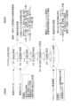
- Fig. 4 shows a flow for creating the NC program 73.
- the program can be created by following the flow of steps (hereinafter simply referred to as S) 1 to S7 shown in Fig. 4.
- Fig. 4 also illustrates a comparison between a comparative example (left side of Fig. 4) in which setting information is manually input, and this embodiment (right side of Fig. 4).
- the user operates the touch panel 61 of the machine tool 10 to register setting information for the base material before machining in S1.
- the user registers information on the tools to be used in S2.
- the user selects tools to be attached to each tool mounting portion 45 (holder number) of the turret 43 from the registered tools in S3, and associates the tools with the holder numbers.
- the holder number here is a number that identifies multiple tool mounting portions 45.
- the user sets the order of the machining processes in S4.
- the user sets the machining conditions for each process set in S5 in S4.
- the machining conditions are, for example, the number of rotations (rotation speed) per unit time of the workpiece W, the tool to be used, the feed amount, etc.
- the user sets dimensional values (cutting diameter, etc.) in S6. This allows the setting information for creating the NC program 73 to be registered, and the NC program 73 to be created. Then, in S7, the user executes a simulation to check whether interference between the workpiece W and the tool occurs in each process of the created NC program 73. Note that the content and processing order of each step of S1 to S7 described above are merely examples.
- the control device 22 of this embodiment acquires the size of the workpiece W and the tool based on the imaging data (mounting state) of the imaging device 56, and automatically sets it as the above-mentioned setting information.
- Objects for which the mounting state is acquired include, for example, the workpiece W, chuck jaws 32, jigs, tools (cutting edge 33A, tip 33B, shank 33C, etc.), holder 37, etc.
- the imaging device 56 is capable of changing the imaging direction and imaging position by the movable part 59.
- the machine tool 10 may be configured to include multiple imaging devices 56, and multiple imaging devices 56 may be installed so that each of the above-mentioned objects can be imaged.
- the control device 22 acquires setting information for the workpiece W based on the imaging data of the imaging device 56. Specifically, the control device 22 acquires, for example, the size (dimensions, length) of the base material before machining and the protrusion amount of the base material based on the imaging data, and sets the acquired values as setting information for creating the NC program 73.
- the protrusion amount of the base material is, for example, the amount (length) by which the base material seated on the backing plate 31 of the chuck mechanism 28 protrudes from the chuck jaws 32.
- the user After the user installs the chuck mechanism 28 (chuck jaws 32 and backing plate 31), base material, holder 37, cutting tool 33, etc. to be used in the next processing in response to a change of setup, the user operates the touch panel 61 to instruct the machine tool 10 to acquire and register the setting information.
- the control device 22 receives an instruction from the user via the touch panel 61, the CPU 71 executes the registration program 75 and controls the movable part 59 to position the imaging device 56 at each imaging position.
- the control device 22 controls the movable part 59 to adjust the imaging direction and controls the reflection suppression part 60 to adjust the rotation angle of the polarizing filter to capture an image of the chuck mechanism 28 and the base material.
- the control device 22 processes the image data to acquire the base material size and the protrusion amount of the base material.
- the control device 22 sets the acquired values as setting information for creating the above-mentioned NC program 73. This allows the variables of the code of the NC program 73 and the parameters read from the code, etc. to be registered.
- the acquired setting information may be used not only for creating the NC program 73, but also for the setting values (offset values, correction values, etc.) of the machine tool 10. The same applies to the setting information acquired from the mounting state of the tool, which will be described later.
- the amount of protrusion of the tool is, for example, a value indicating the distance (deviation) from a reference position to the position of the cutting edge of each tool, and is the amount (setting value, offset value) by which the position of the cutting edge is adjusted in the NC program 73.
- the storage device 72 stores reference data 104 that serves as a reference for determining the type of tool or tip 33B.
- the shank 33C and cutting edge 33A attached to the turret 43 each have a different structure depending on the machining position (outer shape, inner diameter), shape, purpose, etc.
- the reference data 104 stores shape data for the tool (cutting edge 33A, tip 33B, shank 33C), etc.
- This shape data may be two-dimensional data or three-dimensional data.
- the shape data may also be imaging data obtained by imaging the tool in advance, or CAD data created by the tool manufacturer.
- the reference data 104 may not be data separate from the registration program 75, but may be part of the data for the registration program 75.
- the control device 22 compares the overall shape of the tool and the shape of a part of the tip 33B, etc., detected from the imaging data by image processing with the shape data included in the reference data 104, and detects the type of tool, the type of tip, etc. by finding matching shape data.
- the control device 22 may also obtain other setting information such as the width of the tool and the diameter of the rotating tool (such as a drill) by performing image processing on the imaging data.
- the control device 22 may also obtain the shape and angle of the tip 33B, such as the nose R, cutting angle, and cutting edge angle, by performing image processing on the imaging data.
- each of the tips 33B is held at a different holding position relative to the turret 43 in the Z-axis direction and the X-axis direction. Therefore, even if the turret 43 is slid to the same position in the Z-axis direction and the X-axis direction when the tool is indexed, and each of the tips 33B is indexed to the same rotational position, each of the cutting edges of the tips 33B will be positioned at a different position (XZ coordinate).
- the control device 22 obtains the length L from the reference position in the Z-axis direction to the cutting edge of the tip 33B from the imaging data.
- the control device 22 sets the amount by which the cutting edge position is adjusted (the protrusion amount) in the NC program 73 based on the obtained length L. This allows the cutting edges of the tool indexed to the working position to be positioned at the same position in the Z-axis direction. Similarly, in the X-axis direction, the same position can be placed by obtaining and setting the adjustment amount from the imaging data.
- the control device 22 may also detect the amount of wear of the tool (tip 33B) based on the imaging data and use it as a correction value. As described above, when a sensor (such as a 3D scanner) is used as the acquisition device, the control device 22 may acquire (sense) the attachment state of the workpiece W or tool using the sensor, and detect and set the setting information (type, position, shape, etc.) based on the acquired state. The control device 22 may also execute a correct/incorrect judgment between the information acquired by the imaging device 56 and the information input by the user.
- a sensor such as a 3D scanner
- control device 22 may obtain the type of tool based on the imaging data and obtain the protrusion amount using the tool setter 57.
- the control device 22 performs imaging using the imaging device 56 and detects the type of tool by matching the imaging data with the reference data 104.
- the control device 22 controls the sensor drive unit 57C of the tool setter 57 to place the cutting edge detection sensor 57B at a detection position that contacts the cutting edge of the tool, and detects the position of the cutting edge of the tool using the tool setter 57.
- the control device 22 detects the position of the cutting edge based on the XZ coordinates of the turret 43 at the timing when a detection signal indicating contact with the cutting edge is input from the tool setter 57, and sets the protrusion amount of the tool based on the detected cutting edge position.
- the control device 22 sets the set protrusion amount as setting information for the NC program 73. This allows the imaging device 56 and the tool setter 57 to be used together to set the setting information. In cases where the recognition rate of the imaging device 56 is reduced due to the influence of coolant or cutting chips, the contact-type tool setter 57 can be used together to improve the accuracy of the setting information.
- the information detected by the tool setter 57 is not limited to the protrusion amount, but may be other information such as the tool width.
- the control device 22 of this embodiment has a function of outputting data that can be used in a simulation environment based on the imaging data captured by the imaging device 56, as shown in function 2 of FIG. 4.
- the imaging device 56 is capable of capturing images of both the mounting state of the workpiece W in the work spindle device 11 and the mounting state of the tool in the turret 43.
- the work spindle device 11 can be fitted with chuck jaws 32 for chucking the workpiece W, and the chuck jaws 32 can be changed according to the type of workpiece W.
- the control device 22 outputs CAD data of the shape of the workpiece W, the shape of the chuck jaws 32, and the shape of the tool based on the imaging data captured by the imaging device 56.
- the control device 22 may generate and output 3D CAD data from a 3D image of the workpiece W.
- This allows the user to reduce the burden of registration work in constructing a simulation environment by having a PC or the like of a CADCAM system read and register the CAD data output from the control device 22.
- the control device 22 outputs the shape of the chuck jaws 32 and the shape of the tool as 3D CAD data, similar to the shape of the workpiece W.
- control device 22 does not have to output CAD data for the three shapes of the shape of the workpiece W, the shape of the chuck jaws 32, and the shape of the tool.
- the control device 22 may be configured to be able to output CAD data for at least one of the three shapes.
- the data format output by the control device 22 can be appropriately adopted as long as it is a format that can be read in the environment of a system that executes a simulation, such as a CADCAM system.
- the control device 22 may take an image of the workpiece W, etc. with the 2D camera 58, detect edge point cloud data from the two-dimensional image data, and generate 2D or 3D CAD data.
- the control device 22 may not generate CAD data.
- CAD data of each type of chuck jaw 32 or tool may be stored in the storage device 72 in advance.
- the CAD data of the chuck jaw 32, etc. may be stored in association with identification information indicating the type of the chuck jaw 32, etc.
- the control device 22 detects the type of the chuck jaw 32, etc. that is actually attached based on the image data of the imaging device 56.
- the control device 22 may find and output CAD data of a type that matches the detected type of the chuck jaw 32, etc. from the storage device 72.
- the method of transmitting data from the machine tool 10 to the CADCAM system is not particularly limited.
- the control device 22 may transmit the CAD data to the CADCAM system via the network.
- the control device 22 may output the CAD data to an external recording medium such as a USB memory.
- the control device 22 may output other information required for the simulation (such as an NC program 73) together with the CAD data.
- this NC program 73 one created by inputting code or using an interactive function based on the setting information described above can be used.
- the information that can be registered (imported) in the simulation environment by outputting the above-mentioned CAD data includes the following information in addition to the above-mentioned shapes of the workpiece W and tools.
- the CADCAM system can register the type and shape of the chuck jaws 32 from the CAD data.
- the work size, the protrusion amount of the workpiece W, the type of jig used in the chuck mechanism 28, etc. can be registered.
- the control device 22 can output the above-mentioned information on the type of the chuck mechanism 28 as character information separately from the CAD data, and have the CADCAM system read the type of the chuck mechanism 28 from the character information.
- the simulation may also be performed by a device other than a CADCAM system.
- the control device 22 may determine interference between components based on the shapes and sizes of the chuck jaws 32, workpiece W, and tools obtained from imaging data, and the positions of the components in each process.
- the simulation may be performed by the machine tool 10. Therefore, the device that performs the simulation and the simulation method can be changed as appropriate.
- the jaw database 105 (Regarding the nail database 105) Next, the jaw database 105 will be described.
- different chuck jaws 32 may be used when the diameter of the workpiece W differs by only a few mm.
- the type of chuck jaws 32 differs for each type of workpiece W. For this reason, the user needs to manage a large number of chuck jaws 32 (small jaws).
- the control device 22 can detect the shape and type of the workpiece W and the chuck jaws 32 based on the imaging data.
- control device 22 detects the shape of the workpiece W and the type of the chuck jaws 32 based on the imaging data, and stores the detected shape of the workpiece W and the type of the chuck jaws 32 in association with each other in the jaw database 105.
- the control device 22 detects the shape (outer diameter, axial length, unevenness, holes, etc.) of the base material (workpiece W) before processing from the imaging data.
- the control device 22 also detects the shape of the chuck jaws 32 from the imaging data and determines the type of chuck jaws 32 based on the detected shape and the reference data 104.
- the control device 22 then associates the shape of the base material with the information on the type of chuck jaws 32 and registers them in the jaw database 105.
- the timing of registration is not particularly limited.
- the control device 22 may perform registration, for example, when an instruction is received from the user via the touch panel 61. Alternatively, the control device 22 may perform detection and registration when the processing of the workpiece W for the planned production quantity is completed.
- control device 22 may register the shape of the workpiece W after machining, rather than the base material before machining, in the jaw database 105 in association with the type of chuck jaw 32.
- the jaw database 105 can be used to determine whether the type of workpiece W to be used and the type of chuck jaws 32 are an appropriate combination.
- the user attaches the chuck mechanism 28 (chuck jaws 32) to be used after the changeover to the work spindle device 11, and executes an instruction on the touch panel 61 to confirm whether the combination is correct while the base material is chucked by the chuck jaws 32.
- the control device 22 receives the instruction to the touch panel 61 (an example of an operation input in the present disclosure)
- the control device 22 detects the shape of the base material and the type of chuck jaws 32 based on the imaging data of the imaging device 56, and determines whether the detected combination is registered in the jaw database 105.
- the control device 22 displays on the touch panel 61 that the combination is correct.
- the control device 22 displays an error on the touch panel 61. This allows the user to check whether the type of base material and chuck jaws 32 are correct if an incorrect combination is being prepared. This prevents the user from starting processing with the wrong combination of base material and chuck jaws 32. This also reduces the user's burden of managing the chuck jaws 32. If the detected type of chuck jaws 32 or the shape of the base material is not registered in the jaw database 105, the control device 22 may display a message on the touch panel 61 indicating that it is not registered.
- the data stored in the jaw database 105 is not limited to the above data.
- the protrusion amount of the base material may be registered in the jaw database 105 instead of the shape of the base material.
- the control device 22 may detect the protrusion amount of the chuck jaws 32 and the base material prepared by the user from the imaging data and compare it with the protrusion amount in the jaw database 105. In other words, various data that can determine whether the combination of the workpiece W and the chuck jaws 32 is correct or not can be used as the data to be registered in the jaw database 105.
- the control device 22 may also receive information on the storage location of the chuck jaws 32 from the user and register the received information on the storage location in the jaw database 105 in association with the chuck jaws 32. In this way, the control device 22 can notify the appropriate storage location of the chuck jaws 32 on the touch panel 61 or the like based on the shape of the base material detected from the imaging data and the jaw database 105.
- the control device 22 of this embodiment has a function of creating a procedure manual and registering the procedure manual in the procedure manual data 106.
- the procedure manual is a record of information on the past machining of the workpiece W, and is a record of the state of the machine tool 10 when the target workpiece W was machined.
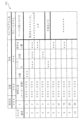
- FIG. 5 shows an example of the procedure manual 111. As shown in FIG. 5, the procedure manual 111 records, for example, information on the order recipient, product number, product name, and name of the NC program 73 of the workpiece W to be machined at the top.
- the holder number which is the identification number of the tool, the name of the tool used, the number of blades of the tool, the nose R, the blade length, and the protrusion amount are recorded. These pieces of information are recorded line by line. Each line corresponds to each of the machining processes. Therefore, information such as the holder number is associated with each process and recorded line by line.
- the procedure manual 111 records supplementary information such as information on how to attach the workpiece W and information on the malfunction that occurred.
- a user writes the above information in a paper procedure manual and stores it as a paper document.
- the control device 22 creates an electronic data procedure manual 111 based on the setting information detected from the image data of the imaging device 56, and executes a process of registering the created procedure manual 111 in the procedure manual data 106.
- the control device 22 creates the procedure manual 111 when the machining of the planned number of workpieces W has been completed.
- the control device 22 detects the type of tool and the tool protrusion amount based on the imaging data of the imaging device 56.
- the control device 22 also detects the order of the processes for machining the workpiece W, the tool number T of the tool used in each process, and the holder number of the tool used based on the NC program 73 used for the machining.
- the control device 22 creates the procedure manual 111 by associating each piece of detected information.
- the memory device 72 stores the manufacturer's model number as information on the type of tool.
- the information on the type of tool is also associated with the tool number T corresponding to that tool.
- the control device 22 enters the tool number T and tool used columns of the procedure manual 111 based on this information.
- the control device 22 displays the format of the procedure manual 111 shown in FIG. 5 on the touch panel 61, for example, and inputs the detected information into each item. This allows the holder number, tool number T, tool used (type of tool), and protrusion amount to be automatically input. This reduces the burden on the user in creating the procedure manual 111. It also reduces the occurrence of writing errors.
- the control device 22 may also automatically input information that can be detected from the imaging data of the imaging device 56, such as the number of teeth of the tool, nose R, and blade length, in addition to the protrusion amount, and that can be left as the procedure manual 111, into the procedure manual 111.
- the control device 22 may also input the program name of the NC program 73 used for machining into the program name field of the procedure manual 111.
- the control device 22 also accepts information such as the order recipient, product number, and installation method on the touch panel 61, inputs it into the procedure manual 111, and registers the completed procedure manual 111 in the procedure manual data 106.
- the control device 22 may also accept corrections to automatically input items (such as the holder number) on the touch panel 61.
- the control device 22 may also execute printing of the created procedure manual 111.
- the control device 22 may also accept information on the order recipient and product number on the touch panel 61, and search for and display the procedure manual 111 from the procedure manual data 106 based on the accepted information. This allows the user to easily search for and reuse the required procedure manual 111.
- the image data captured by the imaging device 56 may be used for purposes other than setting the above-mentioned setting information.
- the control device 22 may display the image data captured by the imaging device 56 on the touch panel 61 in real time.
- the user may want to view the inside of the machining chamber to check for interference, such as during the first machining operation after a setup change.
- the control device 22 may capture an image of the inside of the machining chamber with the imaging device 56 and display the captured image on the touch panel 61. This allows the user to understand the condition inside the machining chamber from the image.
- the work spindle device 11 is an example of a work holding device.
- the turret device 12 is an example of a processing device.
- the control device 22 is an example of a processing device.
- the cutting tool 33 is an example of a tool.
- the imaging device 56 is an example of an acquisition device.
- the touch panel 61 is an example of a user interface.
- the NC program 73 is an example of a processing program.
- the control device 22 sets setting information required for creating an NC program 73 for controlling machining operations based on the image data captured by the image capture device 56. This allows setting information such as the size of the base material, the protrusion amount of the base material, the type of tool, and the protrusion amount of the tool to be set based on the image data. As a result, the setting information required for creating the NC program 73 can be automatically acquired and set.
- the contents of the present disclosure are not limited to the above-described embodiments, but can be embodied in various forms with various modifications and improvements based on the knowledge of those skilled in the art.
- the configuration of the machine tool 10 in the above embodiment is just an example.
- the machine tool 10 may be configured to include a 3D scanner or a touch sensor instead of the imaging device 56.
- the machine tool 10 may not be configured to include the tool setter 57.
- the control device 22 may be configured not to output CAD data based on the imaging data.
- the machine tool 10 is not limited to a turret-type lathe, and may be, for example, a machining center.
- the machine tool 10 may perform imaging of a tool attached to a tool head or a tool stored in an ATC by the imaging device 56, and detect the type and protrusion amount of the tool.
- the contents, order, etc. of the procedure for creating the NC program 73 shown in FIG. 4 are merely an example and can be changed as appropriate.
- the imaging device 56 is configured to be capable of acquiring both the attachment state of the workpiece W in the work spindle device 11 and the attachment state of the tool in the turret device 12, but is not limited to this.
- the imaging device 56 may be configured to be capable of capturing an image of only one of the two attachment states, i.e., only one of the two attachment states.
- control device 22 may be configured to be capable of setting only the setting information related to the workpiece W (base material) or the setting information related to the tool.
- the machining program of the present disclosure is not limited to the NC program 73, but may be another machining program capable of controlling the machine tool 10.
- Machine tool 11 Work spindle device (work holding device), 12 Turret device (machining device), 22 Control device (processing device), 32 Chuck jaws, 33 Cutting tool (tool), 56 Imaging device (acquisition device), 57 Tool setter, 61 Touch panel (user interface), 73 NC program (machining program), 105 Jaw database, 111 Procedure manual, W Work.
Landscapes
- Engineering & Computer Science (AREA)
- Physics & Mathematics (AREA)
- Geometry (AREA)
- Human Computer Interaction (AREA)
- Manufacturing & Machinery (AREA)
- General Physics & Mathematics (AREA)
- Automation & Control Theory (AREA)
- Mechanical Engineering (AREA)
- Machine Tool Sensing Apparatuses (AREA)
Abstract
La présente invention concerne une machine-outil qui peut acquérir des informations de réglage nécessaires à la création d'un programme d'usinage. La machine-outil comprend : un dispositif de maintien de pièce qui maintient une pièce ; un dispositif d'usinage sur lequel peut être monté un outil permettant d'effectuer un usinage sur une pièce maintenue par le dispositif de maintien de pièce ; un dispositif d'acquisition apte à acquérir au moins un état de montage parmi l'état de montage d'une pièce dans le dispositif de maintien de pièce et l'état de montage d'un outil dans le dispositif d'usinage ; et un dispositif de traitement qui définit des informations de réglage nécessaires à la création d'un programme d'usinage pour commander une opération d'usinage sur la base du ou des états de montage acquis par le dispositif d'acquisition.
Priority Applications (1)
| Application Number | Priority Date | Filing Date | Title |
|---|---|---|---|
| PCT/JP2023/030300 WO2025041297A1 (fr) | 2023-08-23 | 2023-08-23 | Machine-outil |
Applications Claiming Priority (1)
| Application Number | Priority Date | Filing Date | Title |
|---|---|---|---|
| PCT/JP2023/030300 WO2025041297A1 (fr) | 2023-08-23 | 2023-08-23 | Machine-outil |
Publications (1)
| Publication Number | Publication Date |
|---|---|
| WO2025041297A1 true WO2025041297A1 (fr) | 2025-02-27 |
Family
ID=94731660
Family Applications (1)
| Application Number | Title | Priority Date | Filing Date |
|---|---|---|---|
| PCT/JP2023/030300 Pending WO2025041297A1 (fr) | 2023-08-23 | 2023-08-23 | Machine-outil |
Country Status (1)
| Country | Link |
|---|---|
| WO (1) | WO2025041297A1 (fr) |
Citations (4)
| Publication number | Priority date | Publication date | Assignee | Title |
|---|---|---|---|---|
| JP2005025668A (ja) * | 2003-07-02 | 2005-01-27 | Kanehira:Kk | 形状加工方法及び形状加工プログラム |
| JP2019185545A (ja) * | 2018-04-13 | 2019-10-24 | ファナック株式会社 | 数値制御システム |
| JP2020032475A (ja) * | 2018-08-28 | 2020-03-05 | ファナック株式会社 | 工具識別装置及び工具識別システム |
| JP2020071703A (ja) * | 2018-10-31 | 2020-05-07 | 株式会社三井ハイテック | 加工装置及び加工方法 |
-
2023
- 2023-08-23 WO PCT/JP2023/030300 patent/WO2025041297A1/fr active Pending
Patent Citations (4)
| Publication number | Priority date | Publication date | Assignee | Title |
|---|---|---|---|---|
| JP2005025668A (ja) * | 2003-07-02 | 2005-01-27 | Kanehira:Kk | 形状加工方法及び形状加工プログラム |
| JP2019185545A (ja) * | 2018-04-13 | 2019-10-24 | ファナック株式会社 | 数値制御システム |
| JP2020032475A (ja) * | 2018-08-28 | 2020-03-05 | ファナック株式会社 | 工具識別装置及び工具識別システム |
| JP2020071703A (ja) * | 2018-10-31 | 2020-05-07 | 株式会社三井ハイテック | 加工装置及び加工方法 |
Similar Documents
| Publication | Publication Date | Title |
|---|---|---|
| CN106346315B (zh) | 能够取得工件原点的机床控制系统以及工件原点设定方法 | |
| US7218995B2 (en) | Device and method for workpiece calibration | |
| JP5725796B2 (ja) | 工具の測定方法及び測定装置、並びに工作機械 | |
| CN104423322B (zh) | 机床的刀具偏移值的自动设定装置及自动设定方法 | |
| KR101161496B1 (ko) | 날끝 위치 검출 방법 및 날끝 위치 검출 장치 | |
| CN106925997B (zh) | 一种自动钻铣系统及方法、钻铣生产线 | |
| JP7068317B2 (ja) | 工作機械を制御する方法 | |
| JP2016093872A (ja) | 工作機械の工具補正値の自動設定装置及び自動設定方法 | |
| JP3333681B2 (ja) | 刃先位置計測装置 | |
| JP6496338B2 (ja) | 工作機械の制御システム | |
| WO2014132845A1 (fr) | Procédé de mesure de forme d'outil et dispositif de mesure de forme d'outil | |
| JPH0852638A (ja) | 干渉チェック方法および加工プログラムチェック方法および加工適否チェック方法 | |
| US12330253B2 (en) | Processing machine and production method for object subject to processing | |
| JP6709280B2 (ja) | 機械加工モジュール、機械加工モジュールのためのアクセサリ・アセンブリ、及び、機械加工モジュールを始動するための方法 | |
| WO2019066034A1 (fr) | Procédé de mesure sur machine et dispositif de commande de machine-outil | |
| CN104768706A (zh) | 加工程序生成方法及装置 | |
| WO2021049186A1 (fr) | Système d'inspection d'outil | |
| JP4180469B2 (ja) | 工作機械の加工適否チェック方法 | |
| WO2020012871A1 (fr) | Machine-outil | |
| CN113953850A (zh) | 一种针对固定直径圆环类工件加工设备 | |
| AU2019211984B2 (en) | Machine tool and method for preparing processing of a material-removing rotational tool | |
| WO2025041297A1 (fr) | Machine-outil | |
| JP2021163107A (ja) | 数値制御装置と数値制御装置の制御方法 | |
| JP2008070143A (ja) | 光学式測定システム | |
| JP5072743B2 (ja) | マイクロマシンおよびマイクロフライスマシン |
Legal Events
| Date | Code | Title | Description |
|---|---|---|---|
| 121 | Ep: the epo has been informed by wipo that ep was designated in this application |
Ref document number: 23949755 Country of ref document: EP Kind code of ref document: A1 |
|
| ENP | Entry into the national phase |
Ref document number: 2025541243 Country of ref document: JP Kind code of ref document: A |
|
| WWE | Wipo information: entry into national phase |
Ref document number: 2025541243 Country of ref document: JP |
|
| NENP | Non-entry into the national phase |
Ref country code: DE |